Embed Size (px)
Citation preview
FlexPod Datacenter with VMware vSphere 5.1 Update 1 and Cisco Nexus 9000 Application Centric Infrastructure (ACI) Design Guide
Last Updated: September 10, 2014
Building Architectures to Solve Business Problems
Cisco Validated Design2
About the Authors
a reference architect in the NetApp Infrastructure and Cloud Engineering team and is ating, validating, supporting, and evangelizing solutions based on NetApp products. mployed in his current role, he worked with NetApp product engineers designing and ovative ways to perform Q&A for NetApp products, including enablement of a large grid sing physical and virtualized compute resources. In these roles, Chris gained expertise in
uting, netboot architectures, traditional and datacenter networking and virtualization.
rt and contribution to the design, validation, and creation of this Cisco Validated Design, uld like to thank:
, Cisco Systems Inc.
sco Systems Inc.
etApp
, NetApp
NetApp
About the AuthorsHaseeb Niazi, Technical Marketing Engineer, UCS Data Center Solutions Engineering, Cisco Systems Inc.
Haseeb has over 15 years of experience at Cisco dealing in Data Center, Security, WAN Optimization, and related technologies. As a member of various solution teams and advanced services, Haseeb has helped many enterprise and service provider customers evaluate and deploy a wide range of Cisco solutions. Haseeb holds a master's degree in Computer Engineering from the University of Southern California.
Chris Reno, Reference Architect, Infrastructure and Cloud Engineering, NetApp
Chris Reno is focused on creBefore being edeveloping inninfrastructure ustateless comp
Acknowledgments
For their suppothe authors wo
Chris O' Brien
Ranga Rao, Ci
John George, N
Lindsey Street
Alex Rosetto,
3
4About Cisco Validated Desig
About the Authors
n (CVD) Program
IM ALL WARRANTIES, INCLUDING, WITHOUT LIMITATION, THE WARRANTY OF
ILITY, FITNESS FOR A PARTICULAR PURPOSE AND NONINFRINGEMENT OR ARISING
SE OF DEALING, USAGE, OR TRADE PRACTICE. IN NO EVENT SHALL CISCO OR ITS
LIABLE FOR ANY INDIRECT, SPECIAL, CONSEQUENTIAL, OR INCIDENTAL DAMAGES,
ITHOUT LIMITATION, LOST PROFITS OR LOSS OR DAMAGE TO DATA ARISING OUT OF
ABILITY TO USE THE DESIGNS, EVEN IF CISCO OR ITS SUPPLIERS HAVE BEEN ADVISED
IBILITY OF SUCH DAMAGES.
ARE SUBJECT TO CHANGE WITHOUT NOTICE. USERS ARE SOLELY RESPONSIBLE FOR
TION OF THE DESIGNS. THE DESIGNS DO NOT CONSTITUTE THE TECHNICAL OR
SSIONAL ADVICE OF CISCO, ITS SUPPLIERS OR PARTNERS. USERS SHOULD CONSULT
CHNICAL ADVISORS BEFORE IMPLEMENTING THE DESIGNS. RESULTS MAY VARY
N FACTORS NOT TESTED BY CISCO.
Cisco Eos, Cisco Lumin, Cisco Nexus, Cisco StadiumVision, Cisco TelePresence, Cisco
co logo, DCE, and Welcome to the Human Network are trademarks; Changing the Way We
y, and Learn and Cisco Store are service marks; and Access Registrar, Aironet, AsyncOS,
eeting To You, Catalyst, CCDA, CCDP, CCIE, CCIP, CCNA, CCNP, CCSP, CCVP, Cisco, the
Internetwork Expert logo, Cisco IOS, Cisco Press, Cisco Systems, Cisco Systems Capital,
ems logo, Cisco Unity, Collaboration Without Limitation, EtherFast, EtherSwitch, Event Cen-
ollow Me Browsing, FormShare, GigaDrive, HomeLink, Internet Quotient, IOS, iPhone,
onPort, the IronPort logo, LightStream, Linksys, MediaTone, MeetingPlace, MeetingPlace
MGX, Networkers, Networking Academy, Network Registrar, PCNow, PIX, PowerPanels,
criptShare, SenderBase, SMARTnet, Spectrum Expert, StackWise, The Fastest Way to
nternet Quotient, TransPath, WebEx, and the WebEx logo are registered trademarks of
, Inc. and/or its affiliates in the United States and certain other countries.
arks mentioned in this document or website are the property of their respective owners.
word partner does not imply a partnership relationship between Cisco and any other com-
Systems, Inc. All rights reserved
About Cisco Validated Design (CVD) Program
The CVD program consists of systems and solutions designed, tested, and documented to facilitate
faster, more reliable, and more predictable customer deployments. For more information visit
http://www.cisco.com/go/designzone.
ALL DESIGNS, SPECIFICATIONS, STATEMENTS, INFORMATION, AND RECOMMENDATIONS (COLLEC-
TIVELY, "DESIGNS") IN THIS MANUAL ARE PRESENTED "AS IS," WITH ALL FAULTS. CISCO AND ITS SUP-
PLIERS DISCLA
MERCHANTAB
FROM A COUR
SUPPLIERS BE
INCLUDING, W
THE USE OR IN
OF THE POSS
THE DESIGNS
THEIR APPLICA
OTHER PROFE
THEIR OWN TE
DEPENDING O
CCDE, CCENT,
WebEx, the Cis
Work, Live, Pla
Bringing the M
Cisco Certified
the Cisco Syst
ter, Fast Step, F
iQuick Study, Ir
Chime Sound,
ProConnect, S
Increase Your I
Cisco Systems
All other tradem
The use of the
pany. (0809R)
© 2014 Cisco
FlexPod Datacenter with VMware vSphere 5.1 Update 1 and Cisco Nexus 9000 Application Centric Infrastructure (ACI) Design Guide
About this DocumentCisco® Validated Designs include systems and solutions that are designed, tested, and documented to facilitate and improve customer deployments. These designs incorporate a wide range of technologies and products into a portfolio of solutions that have been developed to address the business needs of customers.
This document describes the Cisco and NetApp® VMware vSphere® 5.1 Update 1 on FlexPod® solution with Cisco Application Centric Infrastructure (ACI). Cisco ACI is a holistic architecture that introduces hardware and software innovations built upon the new Cisco Nexus 9000® Series product line. Cisco ACI provides a centralized policy driven application deployment architecture, which is managed through the Cisco Application Policy Infrastructure Controller (APIC). Cisco ACI delivers software flexibility with the scalability of hardware performance.
FlexPod with Cisco ACI is a predesigned, best practice data center architecture that is built on the Cisco Unified Computing System (UCS), the Cisco Nexus® 9000 family of switches, and NetApp fabric-attached storage (FAS) or V-Series systems. Some of the key design details and best practices of this new architecture are covered in the sections that follow.
AudienceThe audience of this document includes, but is not limited to, sales engineers, field consultants, professional services, IT managers, partner engineers, and customers who want to take advantage of an infrastructure that is built to deliver IT efficiency and enable IT innovation.
Introduction
IntroductionIndustry trends indicate a vast data center transformation toward shared infrastructure and cloud computing. Business agility requires application agility, so IT teams need to provision applications in hours instead of months. Resources need to scale up (or down) in minutes, not hours.
To simplify the evolution to a shared cloud infrastructure based on an application driven policy model, Cisco and NetApp have developed the solution called VMware vSphere® on FlexPod with Cisco Application Centric Infrastructure (ACI). Cisco ACI in the data center is a holistic architecture with centralized automation and policy-driven application profiles that delivers software flexibility with hardware performance.
Changes in FlexPod
The following design elements distinguish this version of FlexPod from previous models:
• Validation of Cisco's ACI on Cisco Nexus 9000 Series Switches
• Support for the Cisco UCS 2.2 release
• Fabric Interconnect direct connect support for Cisco UCS C-Series
• Support for the latest release of NetApp Data ONTAP® 8.2
• An IP-based storage design supporting both NAS datastores and iSCSI based SAN LUNs.
• Support for direct attached Fiber Chanel storage access for boot LUNs
• Application design guidance for multi-tiered applications using Cisco ACI application profiles and policies
Problem Statement
As customers transition toward shared infrastructure or cloud computing they face a number of challenges such as:
• How do I begin the transition?
• What will my return on investment (ROI) be?
• How do I manage the infrastructure?
• How do I plan for growth?
The FlexPod architecture is designed to help customers answer these questions with proven guidance and measurable value. By introducing standardization, FlexPod helps customers mitigate the risk and uncertainty involved in planning, designing, and implementing a new data center infrastructure. The result is a more predictive and adaptable architecture capable of meeting and exceeding customers' IT demands.
FlexPod Program Benefits
Cisco and NetApp have carefully validated and verified the FlexPod solution architecture and its many use cases while creating a portfolio of detailed documentation, information, and references to assist customers in transforming their data centers to this shared infrastructure model. This portfolio includes, but is not limited to the following items:
6FlexPod Datacenter with VMware vSphere 5.1 Update 1 and Cisco Nexus 9000 Application Centric Infrastructure (ACI) Design Guide
FlexPod System Overview
• Best practice architectural design
• Workload sizing and scaling guidance
• Implementation and deployment instructions
• Technical specifications (rules for what is a FlexPod configuration)
• Frequently asked questions (FAQs)
• Cisco Validated Designs (CVDs) and NetApp Validated Architectures (NVAs) covering a variety of use cases
Cisco and NetApp have also built a robust and experienced support team focused on FlexPod solutions, from customer account and technical sales representatives to professional services and technical support engineers. The support alliance between NetApp and Cisco gives customers and channel services partners direct access to technical experts who collaborate with cross vendors and have access to shared lab resources to resolve potential issues.
FlexPod supports tight integration with virtualized and cloud infrastructures, making it the logical choice for long-term investment. FlexPod also provides a uniform approach to IT architecture, offering a well-characterized and documented shared pool of resources for application workloads. FlexPod delivers operational efficiency and consistency with the versatility to meet a variety of SLAs and IT initiatives, including:
• Application rollouts or application migrations
• Business continuity and disaster recovery
• Desktop virtualization
• Cloud delivery models (public, private, hybrid) and service models (IaaS, PaaS, SaaS)
• Asset consolidation and virtualization
FlexPod System OverviewFlexPod is a best practice datacenter architecture that includes three components:
• Cisco Unified Computing System (Cisco UCS)
• Cisco Nexus switches
• NetApp fabric-attached storage (FAS) systems
7FlexPod Datacenter with VMware vSphere 5.1 Update 1 and Cisco Nexus 9000 Application Centric Infrastructure (ACI) Design Guide
FlexPod System Overview
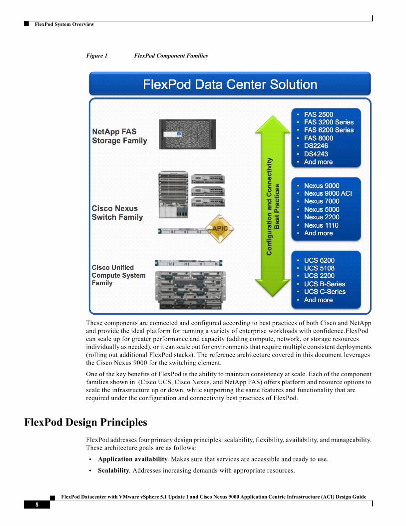
Figure 1 FlexPod Component Families
These components are connected and configured according to best practices of both Cisco and NetApp and provide the ideal platform for running a variety of enterprise workloads with confidence.FlexPod can scale up for greater performance and capacity (adding compute, network, or storage resources individually as needed), or it can scale out for environments that require multiple consistent deployments (rolling out additional FlexPod stacks). The reference architecture covered in this document leverages the Cisco Nexus 9000 for the switching element.
One of the key benefits of FlexPod is the ability to maintain consistency at scale. Each of the component families shown in (Cisco UCS, Cisco Nexus, and NetApp FAS) offers platform and resource options to scale the infrastructure up or down, while supporting the same features and functionality that are required under the configuration and connectivity best practices of FlexPod.
FlexPod Design Principles
FlexPod addresses four primary design principles: scalability, flexibility, availability, and manageability. These architecture goals are as follows:
• Application availability. Makes sure that services are accessible and ready to use.
• Scalability. Addresses increasing demands with appropriate resources.
8FlexPod Datacenter with VMware vSphere 5.1 Update 1 and Cisco Nexus 9000 Application Centric Infrastructure (ACI) Design Guide
FlexPod System Overview
• Flexibility. Provides new services or recovers resources without requiring infrastructure modification.
• Manageability. Facilitates efficient infrastructure operations through open standards and APIs.
Note Performance is a key design criterion that is not directly addressed in this document. It has been addressed in other collateral, benchmarking, and solution testing efforts. This design guide validates the functionality.
FlexPod and Application Centric Infrastructure
The Cisco Nexus 9000 family of switches supports two modes of operation: NxOS standalone mode and Application Centric Infrastructure (ACI) fabric mode. In standalone mode, the switch performs as a typical Nexus switch with increased port density, low latency and 40G connectivity. In fabric mode, the administrator can take advantage of Cisco ACI. Cisco Nexus 9000 based FlexPod design with Cisco ACI consists of Cisco Nexus 9500 and 9300 based spine/leaf switching architecture controlled using a cluster of three Application Policy Infrastructure Controllers (APICs).
Cisco ACI delivers a resilient fabric to satisfy today's dynamic applications. ACI leverages a network fabric that employs industry proven protocols coupled with innovative technologies to create a flexible, scalable, and highly available architecture of low-latency, high-bandwidth links. This fabric delivers application instantiations through the use of profiles, that house the requisite characteristics to enable end-to-end connectivity.
The ACI fabric is designed to support the industry trends of management automation, programmatic policies, and dynamic workload provisioning. The ACI fabric accomplishes this with a combination of hardware, policy-based control systems, and closely coupled software to provide advantages not possible in other architectures.
Cisco ACI Fabric
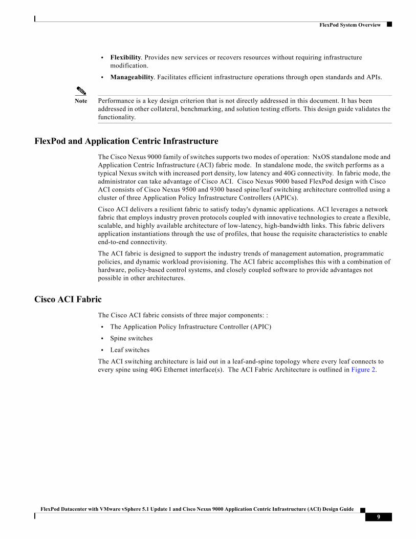
The Cisco ACI fabric consists of three major components: :
• The Application Policy Infrastructure Controller (APIC)
• Spine switches
• Leaf switches
The ACI switching architecture is laid out in a leaf-and-spine topology where every leaf connects to every spine using 40G Ethernet interface(s). The ACI Fabric Architecture is outlined in Figure 2.
9FlexPod Datacenter with VMware vSphere 5.1 Update 1 and Cisco Nexus 9000 Application Centric Infrastructure (ACI) Design Guide
FlexPod System Overview
Figure 2 Cisco ACI Fabric Architecture
The software controller, APIC, is delivered as an appliance and three or more such appliances form a cluster for high availability and enhanced performance. APIC is responsible for all tasks enabling traffic transport including:
• Fabric activation
• Switch firmware management
• Network policy configuration and instantiation
Though the APIC acts as the centralized point of configuration for policy and network connectivity, it is never in line with the data path or the forwarding topology. The fabric can still forward traffic even when communication with the APIC is lost.
APIC provides both a command-line interface (CLI) and graphical-user interface (GUI) to configure and control the ACI fabric. APIC also exposes a northbound API through XML and JavaScript Object Notation (JSON) and an open source southbound API
FlexPod with Cisco ACI—Components
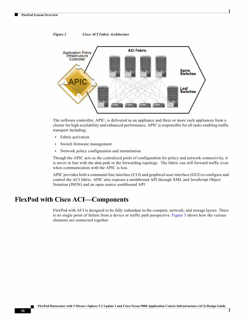
FlexPod with ACI is designed to be fully redundant in the compute, network, and storage layers. There is no single point of failure from a device or traffic path perspective. Figure 3 shows how the various elements are connected together.
10FlexPod Datacenter with VMware vSphere 5.1 Update 1 and Cisco Nexus 9000 Application Centric Infrastructure (ACI) Design Guide
FlexPod System Overview
Figure 3 FlexPod Design with Cisco ACI and NetApp Clustered Data ONTAP
Fabric: As in the previous designs of FlexPod, link aggregation technologies play an important role in FlexPod with ACI providing improved aggregate bandwidth and link resiliency across the solution stack. The NetApp storage controllers, Cisco Unified Computing System, and Cisco Nexus 9000 platforms support active port channeling using 802.3ad standard Link Aggregation Control Protocol (LACP). Port channeling is a link aggregation technique offering link fault tolerance and traffic distribution (load balancing) for improved aggregate bandwidth across member ports. In addition, the Cisco Nexus 9000 series features virtual Port Channel (vPC) capabilities. vPC allows links that are physically connected to two different Cisco Nexus 9000 Series devices to appear as a single "logical" port channel to a third device, essentially offering device fault tolerance. The Cisco UCS Fabric Interconnects and NetApp FAS controllers benefit from the Cisco Nexus vPC abstraction, gaining link and device resiliency as well as full utilization of a non-blocking Ethernet fabric.
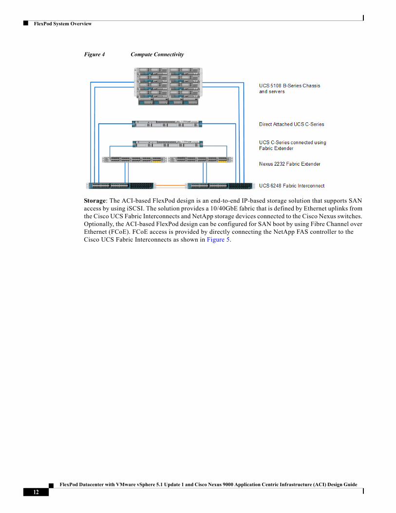
Compute: Each Fabric Interconnect (FI) is connected to both the leaf switches and the links provide a robust 40GbE connection between Cisco Unified Computing System and ACI fabric. Figure 3 illustrates the use of vPC enabled 10GbE uplinks between the Cisco Nexus 9000 leaf switches and Cisco UCS FI. Additional ports can be easily added to the design for increased bandwidth as needed. Each Cisco UCS 5108 chassis is connected to the FIs using a pair of ports from each IO Module for a combined 40G uplink. Current FlexPod design supports Cisco UCS C-Series connectivity both for direct attaching the Cisco UCS C-Series servers into the FIs or by connecting Cisco UCS C-Series to a Cisco Nexus 2232 Fabric Extender hanging off of the Cisco UCS FIs. FlexPod designs mandate Cisco UCS C-Series management using Cisco UCS Manager to provide a uniform look and feel across blade and standalone servers.
11FlexPod Datacenter with VMware vSphere 5.1 Update 1 and Cisco Nexus 9000 Application Centric Infrastructure (ACI) Design Guide
FlexPod System Overview
Figure 4 Compute Connectivity
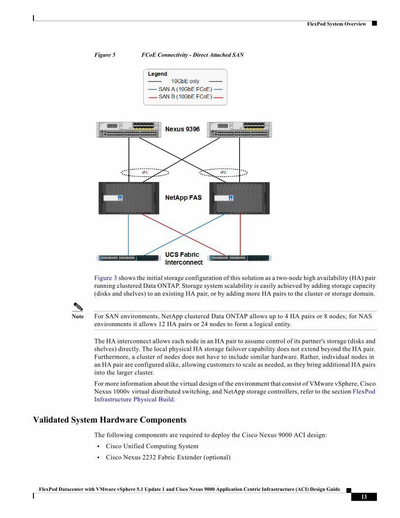
Storage: The ACI-based FlexPod design is an end-to-end IP-based storage solution that supports SAN access by using iSCSI. The solution provides a 10/40GbE fabric that is defined by Ethernet uplinks from the Cisco UCS Fabric Interconnects and NetApp storage devices connected to the Cisco Nexus switches. Optionally, the ACI-based FlexPod design can be configured for SAN boot by using Fibre Channel over Ethernet (FCoE). FCoE access is provided by directly connecting the NetApp FAS controller to the Cisco UCS Fabric Interconnects as shown in Figure 5.
12FlexPod Datacenter with VMware vSphere 5.1 Update 1 and Cisco Nexus 9000 Application Centric Infrastructure (ACI) Design Guide
FlexPod System Overview
Figure 5 FCoE Connectivity - Direct Attached SAN
Figure 3 shows the initial storage configuration of this solution as a two-node high availability (HA) pair running clustered Data ONTAP. Storage system scalability is easily achieved by adding storage capacity (disks and shelves) to an existing HA pair, or by adding more HA pairs to the cluster or storage domain.
Note For SAN environments, NetApp clustered Data ONTAP allows up to 4 HA pairs or 8 nodes; for NAS environments it allows 12 HA pairs or 24 nodes to form a logical entity.
The HA interconnect allows each node in an HA pair to assume control of its partner's storage (disks and shelves) directly. The local physical HA storage failover capability does not extend beyond the HA pair. Furthermore, a cluster of nodes does not have to include similar hardware. Rather, individual nodes in an HA pair are configured alike, allowing customers to scale as needed, as they bring additional HA pairs into the larger cluster.
For more information about the virtual design of the environment that consist of VMware vSphere, Cisco Nexus 1000v virtual distributed switching, and NetApp storage controllers, refer to the section FlexPod Infrastructure Physical Build.
Validated System Hardware Components
The following components are required to deploy the Cisco Nexus 9000 ACI design:
• Cisco Unified Computing System
• Cisco Nexus 2232 Fabric Extender (optional)
13FlexPod Datacenter with VMware vSphere 5.1 Update 1 and Cisco Nexus 9000 Application Centric Infrastructure (ACI) Design Guide
FlexPod System Overview
• Cisco Nexus 9396 Series leaf Switch
• Cisco Nexus 9508 Series spine Switch
• Cisco Application Policy Infrastructure Controller (APIC)
• NetApp Unified Storage
Cisco Unified Computing System
The Cisco Unified Computing System is a next-generation solution for blade and rack server computing. The system integrates a low-latency, lossless 10 Gigabit Ethernet unified network fabric with enterprise-class, x86-architecture servers. The system is an integrated, scalable, multi-chassis platform in which all resources participate in a unified management domain. The Cisco Unified Computing System accelerates the delivery of new services simply, reliably, and securely through end-to-end provisioning and migration support for both virtualized and non-virtualized systems.
The Cisco Unified Computing System consists of the following components:
• Cisco UCS Manager (http://www.cisco.com/en/US/products/ps10281/index.html) provides unified, embedded management of all software and hardware components in the Cisco Unified Computing System.
• Cisco UCS 6200 Series Fabric Interconnects (http://www.cisco.com/en/US/products/ps11544/index.html) is a family of line-rate, low-latency, lossless, 10-Gbps Ethernet and Fibre Channel over Ethernet interconnect switches providing the management and communication backbone for the Cisco Unified Computing System.
• Cisco UCS 5100 Series Blade Server Chassis (http://www.cisco.com/en/US/products/ps10279/index.html) supports up to eight blade servers and up to two fabric extenders in a six-rack unit (RU) enclosure.
• Cisco UCS B-Series Blade Servers (http://www.cisco.com/c/en/us/products/servers-unified-computing/ucs-b-series-blade-servers/index.html) increase performance, efficiency, versatility and productivity with these Intel based blade servers.
• Cisco UCS C-Series Rack Mount Server (http://www.cisco.com/en/US/products/ps10493/index.html) deliver unified computing in an industry-standard form factor to reduce total cost of ownership and increase agility.
• Cisco UCS Adapters (http://www.cisco.com/en/US/products/ps10277/prod_module_series_home.html) wire-once architecture offers a range of options to converge the fabric, optimize virtualization and simplify management.
Cisco Nexus 2232PP 10GE Fabric Extender
The Cisco Nexus 2232PP 10G provides 32 10 Gb Ethernet and Fibre Channel Over Ethernet (FCoE) Small Form-Factor Pluggable Plus (SFP+) server ports and eight 10 Gb Ethernet and FCoE SFP+ uplink ports in a compact 1 rack unit (1RU) form factor.
When a Cisco UCS C-Series Rack-Mount Server is integrated with Cisco UCS Manager, through the Cisco Nexus 2232 platform, the server is managed using the Cisco UCS Manager GUI or Cisco UCS Manager CLI. The Cisco Nexus 2232 provides data and control traffic support for the integrated Cisco UCS C-Series server.
14FlexPod Datacenter with VMware vSphere 5.1 Update 1 and Cisco Nexus 9000 Application Centric Infrastructure (ACI) Design Guide
FlexPod System Overview
Cisco Nexus 9000 Series Switch
The 9000 Series Switches offer both modular and fixed 10/40/100 Gigabit Ethernet switch configurations with scalability up to 30 Tbps of nonblocking performance with less than five-microsecond latency, 1152 10 Gbps or 288 40 Gbps nonblocking Layer 2 and Layer 3 Ethernet ports and wire speed VXLAN gateway, bridging, and routing support.
For more information, refer to: http://www.cisco.com/c/en/us/products/switches/nexus-9000-series-switches/index.html.
NetApp FAS and Data ONTAP
NetApp solutions offer increased availability while consuming fewer IT resources. A NetApp solution includes hardware in the form of FAS controllers and disk storage and the NetApp Data ONTAP operating system that runs on the controllers. Data ONTAP is offered in two modes of operation, 7-Mode and clustered Data ONTAP. The NetApp portfolio offers flexibility for selecting the controller that best fits the customer requirements. The storage efficiency built into Data ONTAP provides substantial space savings, allowing more data to be stored at a lower cost.
NetApp offers the NetApp unified storage architecture which simultaneously supports storage area network (SAN), network-attached storage (NAS), and iSCSI across many operating environments such as VMware, Windows®, and UNIX®. This single architecture provides access to data by using industry-standard protocols, including NFS, CIFS, iSCSI, FCP, SCSI, FTP, and HTTP. Connectivity options include standard Ethernet (10/100/1000, or 10GbE) and Fibre Channel (1, 2, 4, or 8Gb/sec). In addition, all systems can be configured with high-performance solid state drives (SSDs) or serial ATA (SAS) disks for primary storage applications, low-cost SATA disks for secondary applications (such as backup and archive), or a mix of different disk types
.For more information, refer to:
http://www.netapp.com/us/products/platform-os/data-ontap-8/index.aspx.
Note This Cisco Validated Design focuses on clustered Data ONTAP and IP-based storage. FCoE based boot from SAN is covered as an optional configuration.
NetApp Clustered Data ONTAP
With clustered Data ONTAP, NetApp provides enterprise-ready, unified scale-out storage. Developed from a solid foundation of proven Data ONTAP technology and innovation, clustered Data ONTAP is the basis for large virtualized shared storage infrastructures that are architected for nondisruptive operations over the system lifetime. Controller nodes are deployed in HA pairsin a single storage domain or cluster.
Data ONTAP scale-out is a way to respond to growth in a storage environment. As the storage environment grows, additional controllers are added seamlessly to the resource pool residing on a shared storage infrastructure. Host and client connections as well as datastores can move seamlessly and nondisruptively anywhere in the resource pool, so that existing workloads can be easily balanced over the available resources, and new workloads can be easily deployed. Technology refreshes (replacing disk shelves, adding or completely replacing storage controllers) are accomplished while the environment remains online and continues serving data. Data ONTAP is the first product to offer a complete scale-out solution, and it offers an adaptable, always-available storage infrastructure for today's highly virtualized environment.
15FlexPod Datacenter with VMware vSphere 5.1 Update 1 and Cisco Nexus 9000 Application Centric Infrastructure (ACI) Design Guide
FlexPod System Overview
NetApp Storage Virtual Machines
A cluster serves data through at least one and possibly multiple storage virtual machines (SVMs; formerly called Vservers). An SVM is a logical abstraction that represents the set of physical resources of the cluster. Data volumes and network logical interfaces (LIFs) are created and assigned to an SVM and may reside on any node in the cluster to which the SVM has been given access. An SVM may own resources on multiple nodes concurrently, and those resources can be moved nondisruptively from one node to another. For example, a flexible volume can be nondisruptively moved to a new node and aggregate, or a data LIF can be transparently reassigned to a different physical network port. In this manner, the SVM abstracts the cluster hardware and is not tied to specific physical hardware.
An SVM is capable of supporting multiple data protocols concurrently. Volumes within the SVM can be junctioned together to form a single NAS namespace, which makes all of an SVM's data available through a single share or mount point to NFS and CIFS clients. SVMs also support block-based protocols, and LUNs can be created and exported using iSCSI, Fibre Channel, or FCoE. Any or all of these data protocols may be configured for use within a given SVM.
Because it is a secure entity, an SVM is only aware of the resources that have been assigned to it and has no knowledge of other SVMs and their respective resources. Each SVM operates as a separate and distinct entity with its own security domain. Tenants may manage the resources allocated to them through a delegated SVM administration account. Each SVM may connect to unique authentication zones such as Active Directory®, LDAP, or NIS.
VMware vSphere
VMware vSphere is a virtualization platform for holistically managing large collections of infrastructure resources-CPUs, storage, networking-as a seamless, versatile, and dynamic operating environment. Unlike traditional operating systems that manage an individual machine, VMware vSphere aggregates the infrastructure of an entire data center to create a single powerhouse with resources that can be allocated quickly and dynamically to any application in need.
The VMware vSphere environment delivers a robust application environment. For example, with VMware vSphere, all applications can be protected from downtime with VMware High Availability (HA) without the complexity of conventional clustering. In addition, applications can be scaled dynamically to meet changing loads with capabilities such as Hot Add and VMware Distributed Resource Scheduler (DRS).
For more information, refer to:
http://www.vmware.com/products/datacenter-virtualization/vsphere/overview.html
Domain and Element Management
This section of the document provides general descriptions of the domain and element managers used during the validation effort. The following managers were used:
• Cisco UCS Manager
• Cisco UCS Central
• Cisco APIC
• NetApp OnCommand® System and Unified Manager
• NetApp Virtual Storage Console (VSC)
• VMware vCenter™ Server
16FlexPod Datacenter with VMware vSphere 5.1 Update 1 and Cisco Nexus 9000 Application Centric Infrastructure (ACI) Design Guide
FlexPod System Overview
• NetApp Snap Manager and Snap Drive
Cisco Unified Computing System Manager
Cisco UCS Manager provides unified, centralized, embedded management of all Cisco Unified Computing System software and hardware components across multiple chassis and thousands of virtual machines. Administrators use the software to manage the entire Cisco Unified Computing System as a single logical entity through an intuitive GUI, a command-line interface (CLI), or an XML API.
The Cisco UCS Manager resides on a pair of Cisco UCS 6200 Series Fabric Interconnects using a clustered, active-standby configuration for high availability. The software gives administrators a single interface for performing server provisioning, device discovery, inventory, configuration, diagnostics, monitoring, fault detection, auditing, and statistics collection. Cisco UCS Manager service profiles and templates support versatile role- and policy-based management, and system configuration information can be exported to configuration management databases (CMDBs) to facilitate processes based on IT Infrastructure Library (ITIL) concepts. Service profiles benefit both virtualized and non-virtualized environments and increase the mobility of non-virtualized servers, such as when moving workloads from server to server or taking a server offline for service or upgrade. Profiles can also be used in conjunction with virtualization clusters to bring new resources online easily, complementing existing virtual machine mobility.
For more Cisco UCS Manager information, refer to:
http://www.cisco.com/en/US/products/ps10281/index.html
Cisco UCS Central
For Cisco UCS customers managing growth within a single data center, growth across multiple sites, or both, Cisco UCS Central Software centrally manages multiple Cisco UCS domains using the same concepts that Cisco UCS Manager uses to support a single domain. Cisco UCS Central Software manages global resources (including identifiers and policies) that can be consumed within individual Cisco UCS Manager instances. It can delegate the application of policies (embodied in global service profiles) to individual domains, where Cisco UCS Manager puts the policies into effect. In its first release, Cisco UCS Central Software can support up to 10,000 servers in a single data center or distributed around the world in as many domains as are used for the servers.
For more information on Cisco UCS Central, refer to:
http://www.cisco.com/c/en/us/products/servers-unified-computing/ucs-central-software/index.html
Cisco Application Policy Infrastructure Controller (APIC)
The Cisco Application Policy Infrastructure Controller (APIC) is the unifying point of automation and management for the ACI fabric. The Cisco APIC provides centralized access to all fabric information, optimizes the application lifecycle for scale and performance, and supports flexible application provisioning across physical and virtual resources. Some of the key benefits of Cisco APIC are:
• Centralized application-level policy engine for physical, virtual, and cloud infrastructures
• Detailed visibility, telemetry, and health scores by application and by tenant
• Designed around open standards and open APIs
• Robust implementation of multi-tenant security, quality of service (QoS), and high availability
• Integration with management systems such as VMware, Microsoft, and OpenStack
17FlexPod Datacenter with VMware vSphere 5.1 Update 1 and Cisco Nexus 9000 Application Centric Infrastructure (ACI) Design Guide
FlexPod System Overview
Cisco APIC exposes northbound APIs through XML and JSON and provides both a command-line interface (CLI) and GUI which utilize the APIs to manage the fabric holistically. For redundancy and load distribution, three APIC controllers are recommended for managing ACI fabric.
For more information on Cisco APIC, refer to:
http://www.cisco.com/c/en/us/products/cloud-systems-management/application-policy-infrastructure-controller-apic/index.html
NetApp OnCommand System and Unified Manager
NetApp OnCommand System Manager allows storage administrators to manage individual storage systems or clusters of storage systems. Its easy-to-use interface simplifies common storage administration tasks such as creating volumes, LUNs, qtrees, shares, and exports, saving time and helping to prevent errors. System Manager works across all NetApp storage systems: FAS2500 series, FAS3000 series, FAS6000 series, FAS8000 series and V-Series or FlexArray™ systems. NetApp OnCommand Unified Manager complements the features of System Manager by enabling the monitoring and management of storage within the NetApp storage infrastructure.
This solution uses both OnCommand System Manager and OnCommand Unified Manager to provide storage provisioning and monitoring capabilities within the infrastructure.
NetApp Virtual Storage Console
The NetApp Virtual Storage Console (VSC) software delivers storage configuration and monitoring, datastore provisioning, virtual machine (VM) cloning, and backup and recovery of VMs and datastores. VSC also includes an application-programming interface (API) for automated control.
VSC is a single VMware vCenter Server plug-in that provides end-to-end VM lifecycle management for VMware environments that use NetApp storage. VSC is available to all VMware vSphere Clients that connect to the vCenter Server. This availability is different from a client-side plug-in that must be installed on every VMware vSphere Client. The VSC software can be installed either on the vCenter Server or on a separate Microsoft Windows Server® instance or VM.
VMware vCenter Server
VMware vCenter Server is the simplest and most efficient way to manage VMware vSphere, irrespective of the number of VMs you have. It provides unified management of all hosts and VMs from a single console and aggregates performance monitoring of clusters, hosts, and VMs. VMware vCenter Server gives administrators a deep insight into the status and configuration of compute clusters, hosts, VMs, storage, the guest OS, and other critical components of a virtual infrastructure. A single administrator can manage 100 or more virtualization environment workloads using VMware vCenter Server, more than doubling typical productivity in managing physical infrastructure. VMware vCenter manages the rich set of features available in a VMware vSphere environment.
For more information, refer to:
http://www.vmware.com/products/vcenter-server/overview.html
18FlexPod Datacenter with VMware vSphere 5.1 Update 1 and Cisco Nexus 9000 Application Centric Infrastructure (ACI) Design Guide
FlexPod System Overview
NetApp SnapManager and SnapDrive
NetApp SnapManager® and SnapDrive® are two software products used to provision and back up storage for applications under ACI in this solution. The portfolio of SnapManager products is specific to the application being used. SnapDrive is a common component used with all of the SnapManager products.
To create a backup, SnapManager interacts with the application to put the application data in a state such that a consistent NetApp Snapshot® copy of that data can be made. It then signals to SnapDrive to interact with the storage system SVM to create the Snapshot copy, effectively backing up the application data. In addition to managing Snapshot copies of application data, SnapDrive can also be used to accomplish the following tasks:
• Provision application data LUNs in the SVM as mapped disks on the application VM
• Manage Snapshot copies of application VMDK disks on NFS or VMFS datastores
Snapshot copy management of application data LUNs is handled by the interaction of SnapDrive with the SVM management LIF.
FlexPod Infrastructure Design
Hardware and Software Revisions
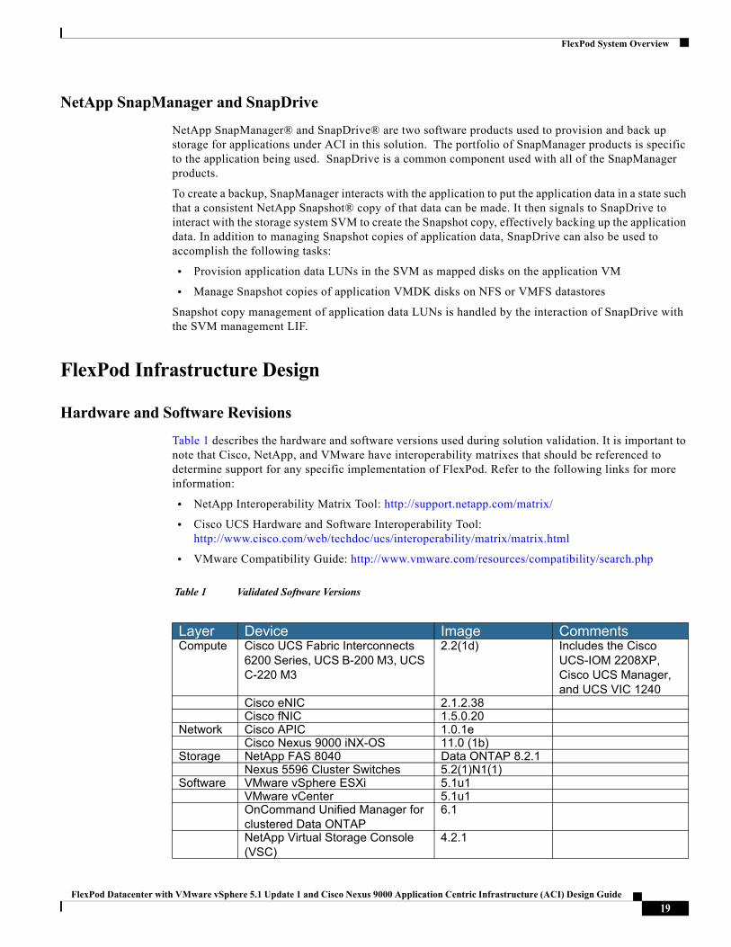
Table 1 describes the hardware and software versions used during solution validation. It is important to note that Cisco, NetApp, and VMware have interoperability matrixes that should be referenced to determine support for any specific implementation of FlexPod. Refer to the following links for more information:
• NetApp Interoperability Matrix Tool: http://support.netapp.com/matrix/
• Cisco UCS Hardware and Software Interoperability Tool: http://www.cisco.com/web/techdoc/ucs/interoperability/matrix/matrix.html
• VMware Compatibility Guide: http://www.vmware.com/resources/compatibility/search.php
Table 1 Validated Software Versions
Layer Device Image CommentsCompute Cisco UCS Fabric Interconnects
6200 Series, UCS B-200 M3, UCS C-220 M3
2.2(1d) Includes the Cisco UCS-IOM 2208XP, Cisco UCS Manager, and UCS VIC 1240
Cisco eNIC 2.1.2.38Cisco fNIC 1.5.0.20
Network Cisco APIC 1.0.1eCisco Nexus 9000 iNX-OS 11.0 (1b)
Storage NetApp FAS 8040 Data ONTAP 8.2.1Nexus 5596 Cluster Switches 5.2(1)N1(1)
Software VMware vSphere ESXi 5.1u1VMware vCenter 5.1u1OnCommand Unified Manager for clustered Data ONTAP
6.1
NetApp Virtual Storage Console (VSC)
4.2.1
19FlexPod Datacenter with VMware vSphere 5.1 Update 1 and Cisco Nexus 9000 Application Centric Infrastructure (ACI) Design Guide
FlexPod System Overview
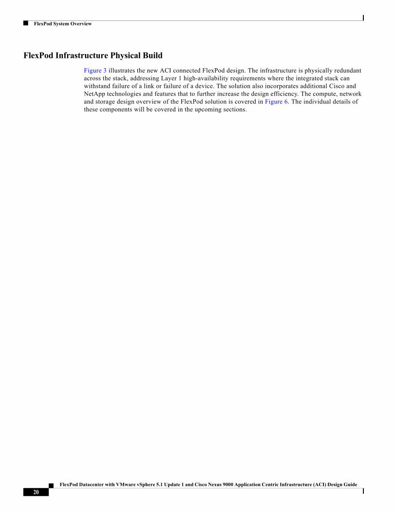
FlexPod Infrastructure Physical Build
Figure 3 illustrates the new ACI connected FlexPod design. The infrastructure is physically redundant across the stack, addressing Layer 1 high-availability requirements where the integrated stack can withstand failure of a link or failure of a device. The solution also incorporates additional Cisco and NetApp technologies and features that to further increase the design efficiency. The compute, network and storage design overview of the FlexPod solution is covered in Figure 6. The individual details of these components will be covered in the upcoming sections.
20FlexPod Datacenter with VMware vSphere 5.1 Update 1 and Cisco Nexus 9000 Application Centric Infrastructure (ACI) Design Guide
FlexPod System Overview
Figure 6 Cisco Nexus 9000 Design for Clustered Data ONTAP
Cisco Unified Computing System
The FlexPod compute design supports both Cisco UCS B-Series and C-Series deployments. The components of the Cisco Unified Computing System offer physical redundancy and a set of logical structures to deliver a very resilient FlexPod compute domain. In this validation effort, multiple Cisco UCS B-Series and C-Series ESXi servers are booted from SAN using iSCSI.
21FlexPod Datacenter with VMware vSphere 5.1 Update 1 and Cisco Nexus 9000 Application Centric Infrastructure (ACI) Design Guide
FlexPod System Overview
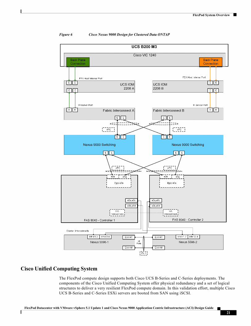
Cisco UCS Physical Connectivity
Cisco UCS Fabric Interconnects are configured with two port-channels, one from each FI, to the Cisco Nexus 9000. These port-channels carry all the data and storage traffic originated on the Cisco Unified Computing System. The validated design utilized two uplinks from each FI to the leaf switches for an aggregate bandwidth of 40GbE (4 x 10GbE). The number of links can be easily increased based on customer data throughput requirements.
Out of Band Network Connectivity
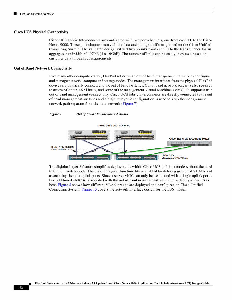
Like many other compute stacks, FlexPod relies on an out of band management network to configure and manage network, compute and storage nodes. The management interfaces from the physical FlexPod devices are physically connected to the out of band switches. Out of band network access is also required to access vCenter, ESXi hosts, and some of the management Virtual Machines (VMs). To support a true out of band management connectivity, Cisco UCS fabric interconnects are directly connected to the out of band management switches and a disjoint layer-2 configuration is used to keep the management network path separate from the data network (Figure 7).
Figure 7 Out of Band Manangement Network
The disjoint Layer 2 feature simplifies deployments within Cisco UCS end-host mode without the need to turn on switch mode. The disjoint layer-2 functionality is enabled by defining groups of VLANs and associating them to uplink ports. Since a server vNIC can only be associated with a single uplink ports, two additional vNICSs, associated with the out of band management uplinks, are deployed per ESXi host. Figure 8 shows how different VLAN groups are deployed and configured on Cisco Unified Computing System. Figure 15 covers the network interface design for the ESXi hosts.
22FlexPod Datacenter with VMware vSphere 5.1 Update 1 and Cisco Nexus 9000 Application Centric Infrastructure (ACI) Design Guide
FlexPod System Overview
Figure 8 Cisco UCS VLAN Group Configuration for Disjoint Layer-2
FCoE Connectivity
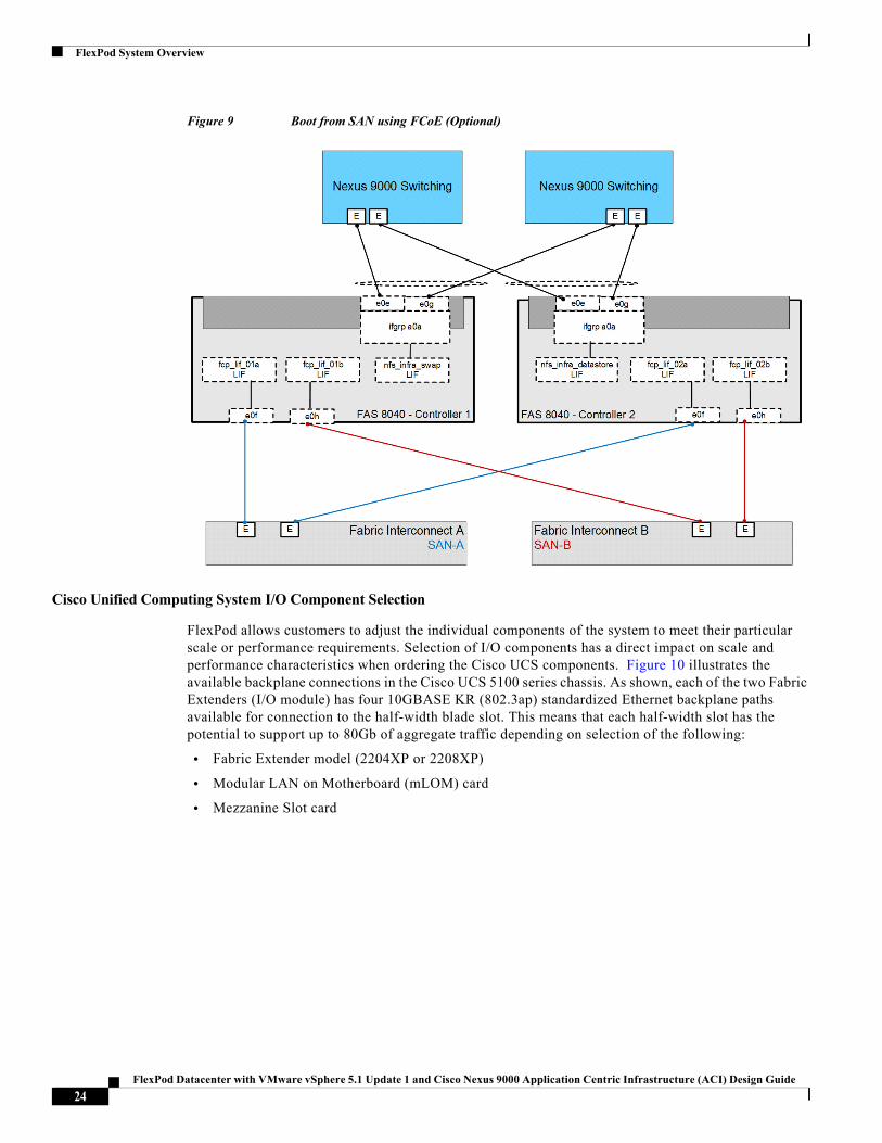
The FlexPod with ACI design optionally supports boot from SAN using FCoE by directly connecting NetApp controller to the Cisco UCS Fabric Interconnects. The updated physical design changes are covered in Figure 9.
In the FCoE design, zoning and related SAN configuration is configured on Cisco UCS Manager and Fabric Interconnects provide the SAN-A and SAN-B separation. On NetApp, Unified Target Adapter is needed to provide physical connectivity.
23FlexPod Datacenter with VMware vSphere 5.1 Update 1 and Cisco Nexus 9000 Application Centric Infrastructure (ACI) Design Guide
FlexPod System Overview
Figure 9 Boot from SAN using FCoE (Optional)
Cisco Unified Computing System I/O Component Selection
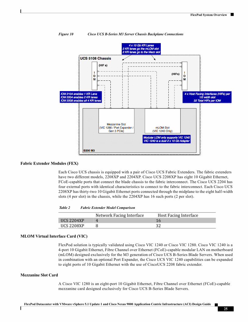
FlexPod allows customers to adjust the individual components of the system to meet their particular scale or performance requirements. Selection of I/O components has a direct impact on scale and performance characteristics when ordering the Cisco UCS components. Figure 10 illustrates the available backplane connections in the Cisco UCS 5100 series chassis. As shown, each of the two Fabric Extenders (I/O module) has four 10GBASE KR (802.3ap) standardized Ethernet backplane paths available for connection to the half-width blade slot. This means that each half-width slot has the potential to support up to 80Gb of aggregate traffic depending on selection of the following:
• Fabric Extender model (2204XP or 2208XP)
• Modular LAN on Motherboard (mLOM) card
• Mezzanine Slot card
24FlexPod Datacenter with VMware vSphere 5.1 Update 1 and Cisco Nexus 9000 Application Centric Infrastructure (ACI) Design Guide
FlexPod System Overview
Figure 10 Cisco UCS B-Series M3 Server Chassis Backplane Connections
Fabric Extender Modules (FEX)
Each Cisco UCS chassis is equipped with a pair of Cisco UCS Fabric Extenders. The fabric extenders have two different models, 2208XP and 2204XP. Cisco UCS 2208XP has eight 10 Gigabit Ethernet, FCoE-capable ports that connect the blade chassis to the fabric interconnect. The Cisco UCS 2204 has four external ports with identical characteristics to connect to the fabric interconnect. Each Cisco UCS 2208XP has thirty-two 10 Gigabit Ethernet ports connected through the midplane to the eight half-width slots (4 per slot) in the chassis, while the 2204XP has 16 such ports (2 per slot).
Table 2 Fabric Extender Model Comparison
MLOM Virtual Interface Card (VIC)
FlexPod solution is typically validated using Cisco VIC 1240 or Cisco VIC 1280. Cisco VIC 1240 is a 4-port 10 Gigabit Ethernet, Fibre Channel over Ethernet (FCoE)-capable modular LAN on motherboard (mLOM) designed exclusively for the M3 generation of Cisco UCS B-Series Blade Servers. When used in combination with an optional Port Expander, the Cisco UCS VIC 1240 capabilities can be expanded to eight ports of 10 Gigabit Ethernet with the use of CiscoUCS 2208 fabric extender.
Mezzanine Slot Card
A Cisco VIC 1280 is an eight-port 10 Gigabit Ethernet, Fibre Channel over Ethernet (FCoE)-capable mezzanine card designed exclusively for Cisco UCS B-Series Blade Servers.
Network Facing Interface Host Facing InterfaceUCS 2204XP 4 16UCS 2208XP 8 32
25FlexPod Datacenter with VMware vSphere 5.1 Update 1 and Cisco Nexus 9000 Application Centric Infrastructure (ACI) Design Guide
FlexPod System Overview
Server Traffic Aggregation
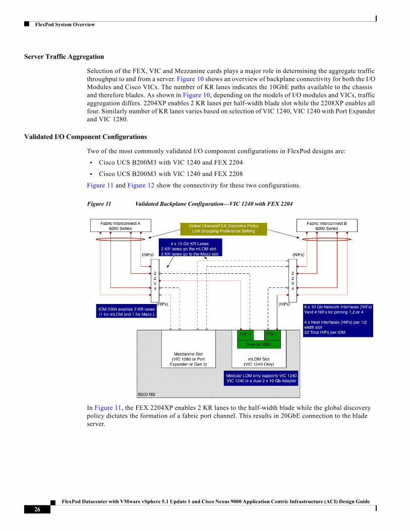
Selection of the FEX, VIC and Mezzanine cards plays a major role in determining the aggregate traffic throughput to and from a server. Figure 10 shows an overview of backplane connectivity for both the I/O Modules and Cisco VICs. The number of KR lanes indicates the 10GbE paths available to the chassis and therefore blades. As shown in Figure 10, depending on the models of I/O modules and VICs, traffic aggregation differs. 2204XP enables 2 KR lanes per half-width blade slot while the 2208XP enables all four. Similarly number of KR lanes varies based on selection of VIC 1240, VIC 1240 with Port Expander and VIC 1280.
Validated I/O Component Configurations
Two of the most commonly validated I/O component configurations in FlexPod designs are:
• Cisco UCS B200M3 with VIC 1240 and FEX 2204
• Cisco UCS B200M3 with VIC 1240 and FEX 2208
Figure 11 and Figure 12 show the connectivity for these two configurations.
Figure 11 Validated Backplane Configuration—VIC 1240 with FEX 2204
In Figure 11, the FEX 2204XP enables 2 KR lanes to the half-width blade while the global discovery policy dictates the formation of a fabric port channel. This results in 20GbE connection to the blade server.
26FlexPod Datacenter with VMware vSphere 5.1 Update 1 and Cisco Nexus 9000 Application Centric Infrastructure (ACI) Design Guide
FlexPod System Overview
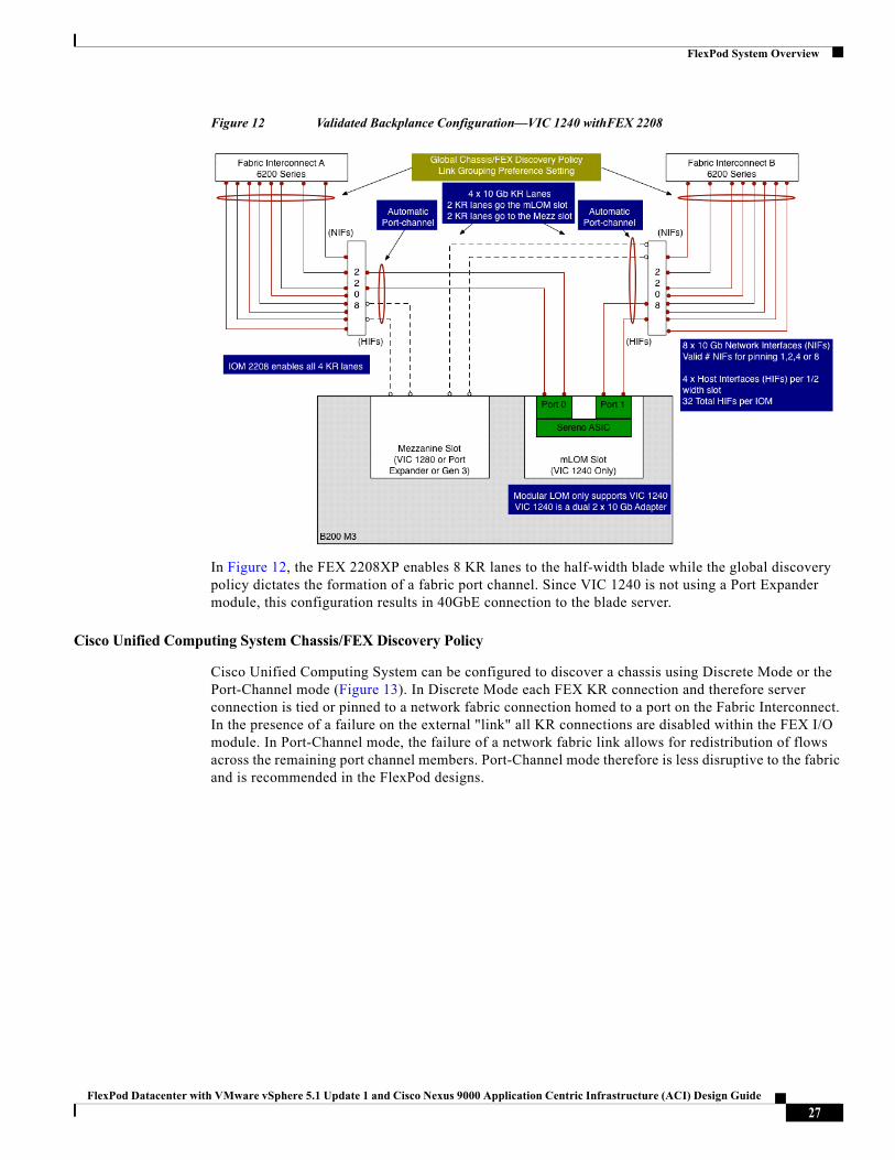
Figure 12 Validated Backplance Configuration—VIC 1240 withFEX 2208
In Figure 12, the FEX 2208XP enables 8 KR lanes to the half-width blade while the global discovery policy dictates the formation of a fabric port channel. Since VIC 1240 is not using a Port Expander module, this configuration results in 40GbE connection to the blade server.
Cisco Unified Computing System Chassis/FEX Discovery Policy
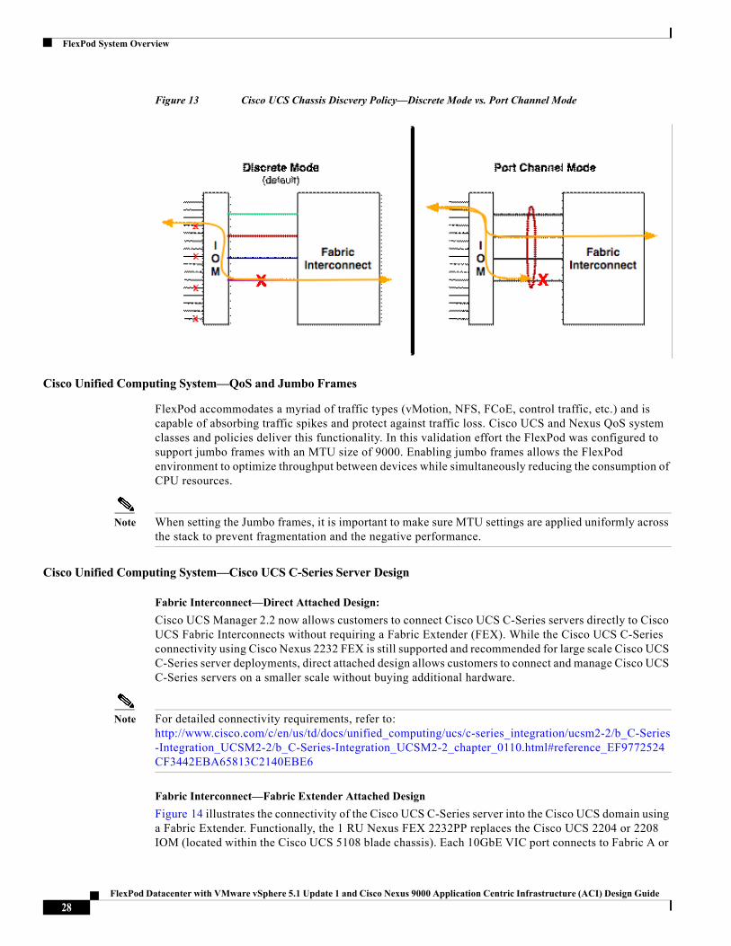
Cisco Unified Computing System can be configured to discover a chassis using Discrete Mode or the Port-Channel mode (Figure 13). In Discrete Mode each FEX KR connection and therefore server connection is tied or pinned to a network fabric connection homed to a port on the Fabric Interconnect. In the presence of a failure on the external "link" all KR connections are disabled within the FEX I/O module. In Port-Channel mode, the failure of a network fabric link allows for redistribution of flows across the remaining port channel members. Port-Channel mode therefore is less disruptive to the fabric and is recommended in the FlexPod designs.
27FlexPod Datacenter with VMware vSphere 5.1 Update 1 and Cisco Nexus 9000 Application Centric Infrastructure (ACI) Design Guide
FlexPod System Overview
Figure 13 Cisco UCS Chassis Discvery Policy—Discrete Mode vs. Port Channel Mode
Cisco Unified Computing System—QoS and Jumbo Frames
FlexPod accommodates a myriad of traffic types (vMotion, NFS, FCoE, control traffic, etc.) and is capable of absorbing traffic spikes and protect against traffic loss. Cisco UCS and Nexus QoS system classes and policies deliver this functionality. In this validation effort the FlexPod was configured to support jumbo frames with an MTU size of 9000. Enabling jumbo frames allows the FlexPod environment to optimize throughput between devices while simultaneously reducing the consumption of CPU resources.
Note When setting the Jumbo frames, it is important to make sure MTU settings are applied uniformly across the stack to prevent fragmentation and the negative performance.
Cisco Unified Computing System—Cisco UCS C-Series Server Design
Fabric Interconnect—Direct Attached Design:
Cisco UCS Manager 2.2 now allows customers to connect Cisco UCS C-Series servers directly to Cisco UCS Fabric Interconnects without requiring a Fabric Extender (FEX). While the Cisco UCS C-Series connectivity using Cisco Nexus 2232 FEX is still supported and recommended for large scale Cisco UCS C-Series server deployments, direct attached design allows customers to connect and manage Cisco UCS C-Series servers on a smaller scale without buying additional hardware.
Note For detailed connectivity requirements, refer to: http://www.cisco.com/c/en/us/td/docs/unified_computing/ucs/c-series_integration/ucsm2-2/b_C-Series-Integration_UCSM2-2/b_C-Series-Integration_UCSM2-2_chapter_0110.html#reference_EF9772524CF3442EBA65813C2140EBE6
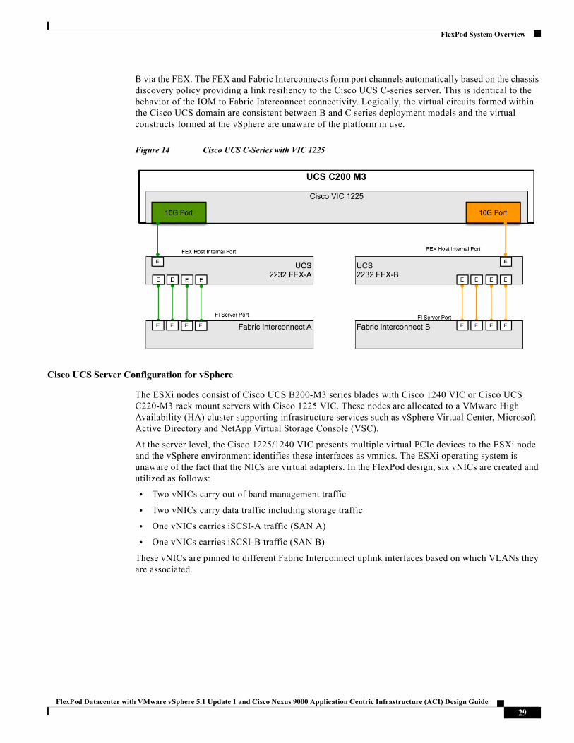
Fabric Interconnect—Fabric Extender Attached Design
Figure 14 illustrates the connectivity of the Cisco UCS C-Series server into the Cisco UCS domain using a Fabric Extender. Functionally, the 1 RU Nexus FEX 2232PP replaces the Cisco UCS 2204 or 2208 IOM (located within the Cisco UCS 5108 blade chassis). Each 10GbE VIC port connects to Fabric A or
28FlexPod Datacenter with VMware vSphere 5.1 Update 1 and Cisco Nexus 9000 Application Centric Infrastructure (ACI) Design Guide
FlexPod System Overview
B via the FEX. The FEX and Fabric Interconnects form port channels automatically based on the chassis discovery policy providing a link resiliency to the Cisco UCS C-series server. This is identical to the behavior of the IOM to Fabric Interconnect connectivity. Logically, the virtual circuits formed within the Cisco UCS domain are consistent between B and C series deployment models and the virtual constructs formed at the vSphere are unaware of the platform in use.
Figure 14 Cisco UCS C-Series with VIC 1225
Cisco UCS Server Configuration for vSphere
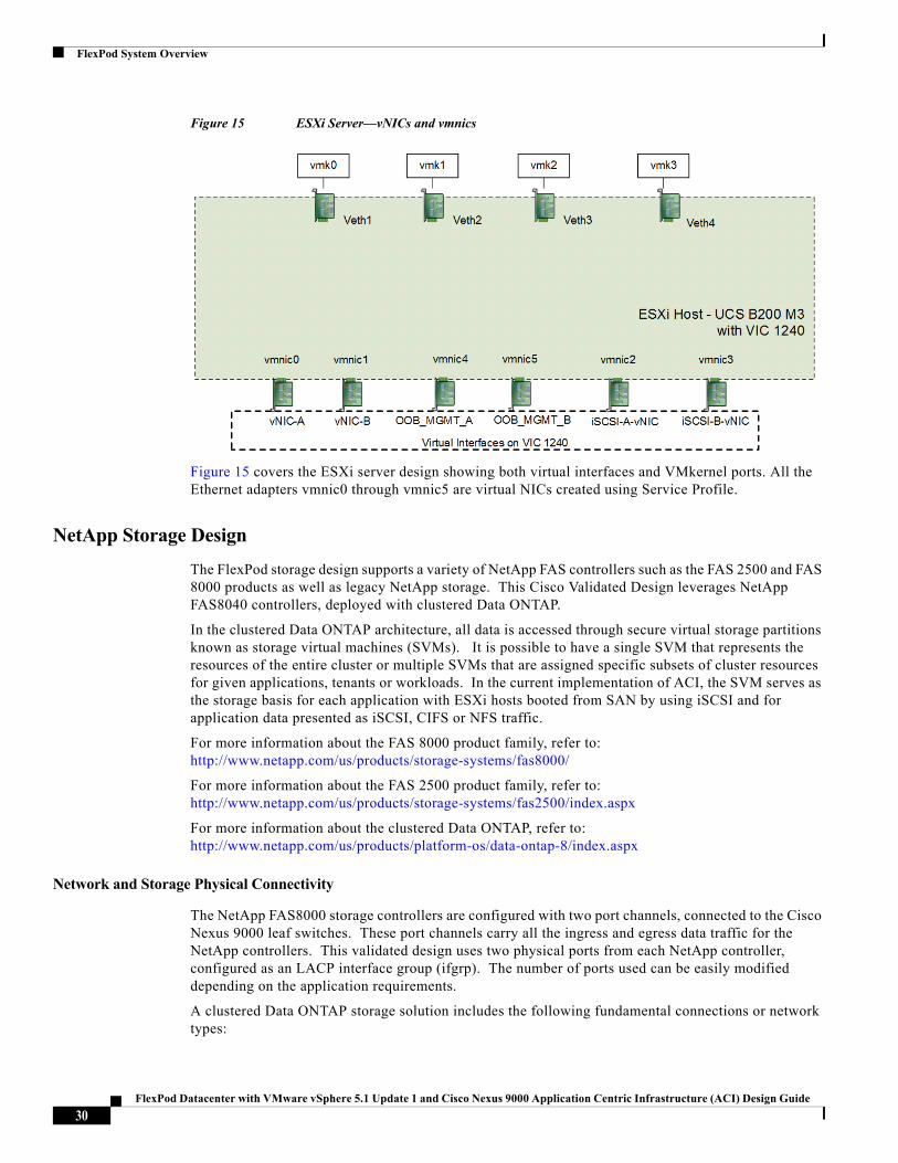
The ESXi nodes consist of Cisco UCS B200-M3 series blades with Cisco 1240 VIC or Cisco UCS C220-M3 rack mount servers with Cisco 1225 VIC. These nodes are allocated to a VMware High Availability (HA) cluster supporting infrastructure services such as vSphere Virtual Center, Microsoft Active Directory and NetApp Virtual Storage Console (VSC).
At the server level, the Cisco 1225/1240 VIC presents multiple virtual PCIe devices to the ESXi node and the vSphere environment identifies these interfaces as vmnics. The ESXi operating system is unaware of the fact that the NICs are virtual adapters. In the FlexPod design, six vNICs are created and utilized as follows:
• Two vNICs carry out of band management traffic
• Two vNICs carry data traffic including storage traffic
• One vNICs carries iSCSI-A traffic (SAN A)
• One vNICs carries iSCSI-B traffic (SAN B)
These vNICs are pinned to different Fabric Interconnect uplink interfaces based on which VLANs they are associated.
29FlexPod Datacenter with VMware vSphere 5.1 Update 1 and Cisco Nexus 9000 Application Centric Infrastructure (ACI) Design Guide
FlexPod System Overview
Figure 15 ESXi Server—vNICs and vmnics
Figure 15 covers the ESXi server design showing both virtual interfaces and VMkernel ports. All the Ethernet adapters vmnic0 through vmnic5 are virtual NICs created using Service Profile.
NetApp Storage Design
The FlexPod storage design supports a variety of NetApp FAS controllers such as the FAS 2500 and FAS 8000 products as well as legacy NetApp storage. This Cisco Validated Design leverages NetApp FAS8040 controllers, deployed with clustered Data ONTAP.
In the clustered Data ONTAP architecture, all data is accessed through secure virtual storage partitions known as storage virtual machines (SVMs). It is possible to have a single SVM that represents the resources of the entire cluster or multiple SVMs that are assigned specific subsets of cluster resources for given applications, tenants or workloads. In the current implementation of ACI, the SVM serves as the storage basis for each application with ESXi hosts booted from SAN by using iSCSI and for application data presented as iSCSI, CIFS or NFS traffic.
For more information about the FAS 8000 product family, refer to: http://www.netapp.com/us/products/storage-systems/fas8000/
For more information about the FAS 2500 product family, refer to: http://www.netapp.com/us/products/storage-systems/fas2500/index.aspx
For more information about the clustered Data ONTAP, refer to: http://www.netapp.com/us/products/platform-os/data-ontap-8/index.aspx
Network and Storage Physical Connectivity
The NetApp FAS8000 storage controllers are configured with two port channels, connected to the Cisco Nexus 9000 leaf switches. These port channels carry all the ingress and egress data traffic for the NetApp controllers. This validated design uses two physical ports from each NetApp controller, configured as an LACP interface group (ifgrp). The number of ports used can be easily modified depending on the application requirements.
A clustered Data ONTAP storage solution includes the following fundamental connections or network types:
30FlexPod Datacenter with VMware vSphere 5.1 Update 1 and Cisco Nexus 9000 Application Centric Infrastructure (ACI) Design Guide
FlexPod System Overview
• HA interconnect. A dedicated interconnect between two nodes to form HA pairs. These pairs are also known as storage failover pairs.
• Cluster interconnect. A dedicated high-speed, low-latency, private network used for communication between nodes. This network can be implemented through the deployment of a switchless cluster or by leveraging dedicated cluster interconnect switches.
Note NetApp switchless cluster, is only appropriate for two node clusters.
• Management network. A network used for the administration of nodes, cluster, and SVMs.
• Data network. A network used by clients to access data.
• Ports. A physical port such as e0a or e1a or a logical port such as a virtual LAN (VLAN) or an interface group.
• Interface groups. A collection of physical ports to create one logical port. The NetApp interface group is a link aggregation technology that can be deployed in single (active/passive), multiple ("always on"), or dynamic (active LACP) mode.
This validation uses two storage nodes configured as a two-node storage failoverpair through an HA interconnect direct connection. The FlexPod design uses the following port and interface assignments:
• Ethernet ports e0e and e0g on each node are members of a multimode LACP interface group for Ethernet data. This design leverages an interface group that has LIFs associated with it to support NFS and iSCSI traffic.
• Ports e0M on each node support a LIF dedicated to node management. Port e0i is defined as a failover port supporting the "node_mgmt" role.
• Port e0i supports cluster management data traffic through the cluster management LIF. This port and LIF allow for administration of the cluster from the failover port and LIF if necessary.
• HA interconnect ports are internal to the chassis.
• Ports e0a, e0b, e0c, and e0d are cluster interconnect ports for data traffic. These ports connect to each of the Cisco Nexus 5596 cluster interconnect switches.
• The Cisco Nexus Cluster Interconnect switches support a single port channel (Po1).
Out of Band Network Connectivity
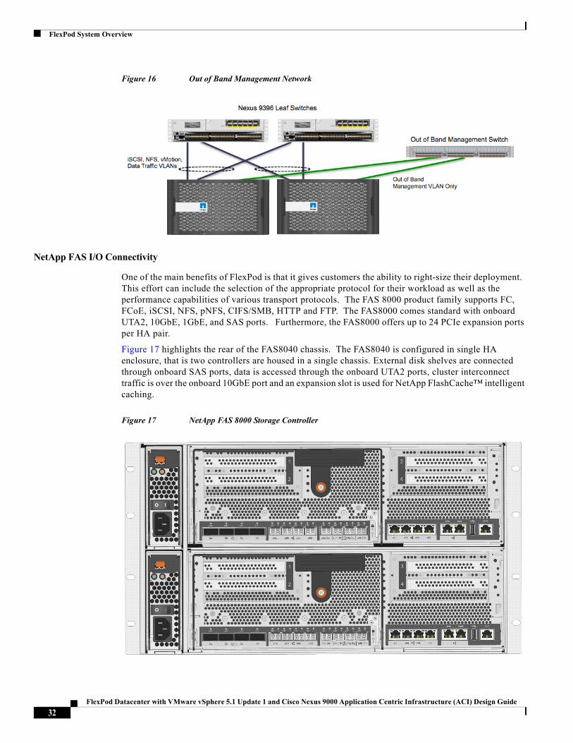
FlexPod leverages out-of-band management networking. Ports e0M on each node support a LIF dedicated to node management. Port e0b is defined as a failover port supporting the "node_mgmt" role. This role allows access to tools such as NetApp VSC. To support out of band management connectivity, the NetApp controllers are directly connected to out of band management switches as shown in Figure 16.
Note The FAS8040 controllers are sold ina single-chassis, dual-controller option only. Figure 16 represents the NetApp storage controllers as a dual chassis dual controllers deployment. Figure 16 shows two FAS8040 controllers for visual purposes.
31FlexPod Datacenter with VMware vSphere 5.1 Update 1 and Cisco Nexus 9000 Application Centric Infrastructure (ACI) Design Guide
FlexPod System Overview
Figure 16 Out of Band Management Network
NetApp FAS I/O Connectivity
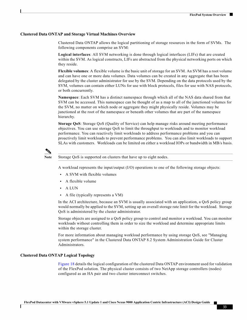
One of the main benefits of FlexPod is that it gives customers the ability to right-size their deployment. This effort can include the selection of the appropriate protocol for their workload as well as the performance capabilities of various transport protocols. The FAS 8000 product family supports FC, FCoE, iSCSI, NFS, pNFS, CIFS/SMB, HTTP and FTP. The FAS8000 comes standard with onboard UTA2, 10GbE, 1GbE, and SAS ports. Furthermore, the FAS8000 offers up to 24 PCIe expansion ports per HA pair.
Figure 17 highlights the rear of the FAS8040 chassis. The FAS8040 is configured in single HA enclosure, that is two controllers are housed in a single chassis. External disk shelves are connected through onboard SAS ports, data is accessed through the onboard UTA2 ports, cluster interconnect traffic is over the onboard 10GbE port and an expansion slot is used for NetApp FlashCache™ intelligent caching.
Figure 17 NetApp FAS 8000 Storage Controller
32FlexPod Datacenter with VMware vSphere 5.1 Update 1 and Cisco Nexus 9000 Application Centric Infrastructure (ACI) Design Guide
FlexPod System Overview
Clustered Data ONTAP and Storage Virtual Machines Overview
Clustered Data ONTAP allows the logical partitioning of storage resources in the form of SVMs. The following components comprise an SVM:
Logical interfaces: All SVM networking is done through logical interfaces (LIFs) that are created within the SVM. As logical constructs, LIFs are abstracted from the physical networking ports on which they reside.
Flexible volumes: A flexible volume is the basic unit of storage for an SVM. An SVM has a root volume and can have one or more data volumes. Data volumes can be created in any aggregate that has been delegated by the cluster administrator for use by the SVM. Depending on the data protocols used by the SVM, volumes can contain either LUNs for use with block protocols, files for use with NAS protocols, or both concurrently.
Namespace: Each SVM has a distinct namespace through which all of the NAS data shared from that SVM can be accessed. This namespace can be thought of as a map to all of the junctioned volumes for the SVM, no matter on which node or aggregate they might physically reside. Volumes may be junctioned at the root of the namespace or beneath other volumes that are part of the namespace hierarchy.
Storage QoS: Storage QoS (Quality of Service) can help manage risks around meeting performance objectives. You can use storage QoS to limit the throughput to workloads and to monitor workload performance. You can reactively limit workloads to address performance problems and you can proactively limit workloads to prevent performance problems. You can also limit workloads to support SLAs with customers. Workloads can be limited on either a workload IOPs or bandwidth in MB/s basis.
Note Storage QoS is supported on clusters that have up to eight nodes.
A workload represents the input/output (I/O) operations to one of the following storage objects:
• A SVM with flexible volumes
• A flexible volume
• A LUN
• A file (typically represents a VM)
In the ACI architecture, because an SVM is usually associated with an application, a QoS policy group would normally be applied to the SVM, setting up an overall storage rate limit for the workload. Storage QoS is administered by the cluster administrator.
Storage objects are assigned to a QoS policy group to control and monitor a workload. You can monitor workloads without controlling them in order to size the workload and determine appropriate limits within the storage cluster.
For more information about managing workload performance by using storage QoS, see "Managing system performance" in the Clustered Data ONTAP 8.2 System Administration Guide for Cluster Administrators.
Clustered Data ONTAP Logical Topology
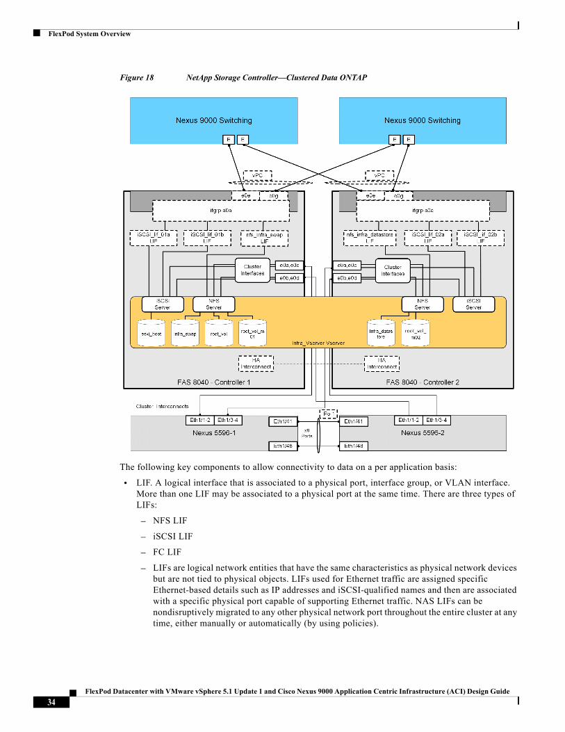
Figure 18 details the logical configuration of the clustered Data ONTAP environment used for validation of the FlexPod solution. The physical cluster consists of two NetApp storage controllers (nodes) configured as an HA pair and two cluster interconnect switches.
33FlexPod Datacenter with VMware vSphere 5.1 Update 1 and Cisco Nexus 9000 Application Centric Infrastructure (ACI) Design Guide
FlexPod System Overview
Figure 18 NetApp Storage Controller—Clustered Data ONTAP
The following key components to allow connectivity to data on a per application basis:
• LIF. A logical interface that is associated to a physical port, interface group, or VLAN interface. More than one LIF may be associated to a physical port at the same time. There are three types of LIFs:
– NFS LIF
– iSCSI LIF
– FC LIF
– LIFs are logical network entities that have the same characteristics as physical network devices but are not tied to physical objects. LIFs used for Ethernet traffic are assigned specific Ethernet-based details such as IP addresses and iSCSI-qualified names and then are associated with a specific physical port capable of supporting Ethernet traffic. NAS LIFs can be nondisruptively migrated to any other physical network port throughout the entire cluster at any time, either manually or automatically (by using policies).
34FlexPod Datacenter with VMware vSphere 5.1 Update 1 and Cisco Nexus 9000 Application Centric Infrastructure (ACI) Design Guide
FlexPod System Overview
In this Cisco Validated Design, LIFs are layered on top of the physical interface groups and are associated with a given VLAN interface. LIFs are then consumed by the SVMs and are typically associated with a given protocol and data store.
• SVMs. An SVM is a secure virtual storage server that contains data volumes and one or more LIFs, through which it serves data to the clients. An SVM securely isolates the shared virtualized data storage and network and appears as a single dedicated server to its clients. Each SVM has a separate administrator authentication domain and can be managed independently by an SVM administrator.
Clustered Data ONTAP Configuration for vSphere
This solution defines a single infrastructure SVM to own and export the data necessary to run the VMware vSphere infrastructure. This SVM specifically owns the following flexible volumes:
• Root volume. A flexible volume that contains the root of the SVM namespace.
• Root volume load-sharing mirrors. Mirrored volume of the root volume to accelerate read throughput. In this instance, they are labeled root_vol_m01 and root_vol_m02.
• Boot volume. A flexible volume that contains ESXi boot LUNs. These ESXi boot LUNs are exported through iSCSI to the Cisco UCS servers.
• Infrastructure datastore volume. A flexible volume that is exported through NFS to the ESXi host and is used as the infrastructure NFS datastore to store VM files.
• Infrastructure swap volume. A flexible volume that is exported through NFS to each ESXi host and used to store VM swap data.
The NFS datastores are mounted on each VMware ESXi host in the VMware cluster and are provided by NetApp clustered Data ONTAP through NFS over the 10GbE network.
The SVM has a minimum of one LIF per protocol per node to maintain volume availability across the cluster nodes. The LIFs use failover groups, which are network polices defining the ports or interface groups available to support a single LIF migration or a group of LIFs migrating within or across nodes in a cluster. Multiple LIFs may be associated with a network port or interface group. In addition to failover groups, the clustered Data ONTAP system uses failover policies. Failover polices define the order in which the ports in the failover group are prioritized. Failover policies define migration policy in the event of port failures, port recoveries, or user-initiated requests.
The most basic possible storage failover scenarios in this cluster are as follows:
• Node 1 fails, and Node 2 takes over Node 1's storage.
• Node 2 fails, and Node 1 takes over Node 2's storage.
The remaining node network connectivity failures are addressed through the redundant port, interface groups, and logical interface abstractions afforded by the clustered Data ONTAP system.
Storage Virtual Machine Layout
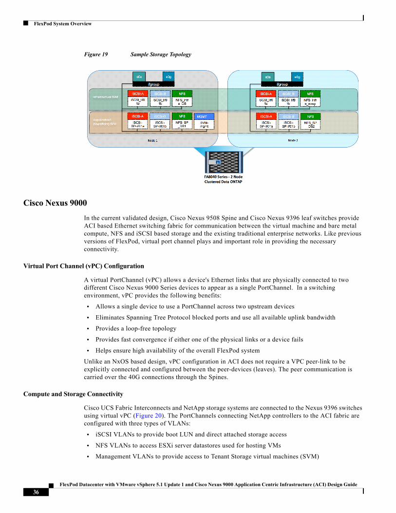
Figure 19 highlights a the storage topology showing SVM and associated LIFs. There are two storage nodes and the SVM's are layered across both controller nodes. Each SVM has its own LIFs configured to support SVM specific storage protocols. Each of these LIFs are mapped to end point groups on the ACI fabric.
35FlexPod Datacenter with VMware vSphere 5.1 Update 1 and Cisco Nexus 9000 Application Centric Infrastructure (ACI) Design Guide
FlexPod System Overview
Figure 19 Sample Storage Topology
Cisco Nexus 9000
In the current validated design, Cisco Nexus 9508 Spine and Cisco Nexus 9396 leaf switches provide ACI based Ethernet switching fabric for communication between the virtual machine and bare metal compute, NFS and iSCSI based storage and the existing traditional enterprise networks. Like previous versions of FlexPod, virtual port channel plays and important role in providing the necessary connectivity.
Virtual Port Channel (vPC) Configuration
A virtual PortChannel (vPC) allows a device's Ethernet links that are physically connected to two different Cisco Nexus 9000 Series devices to appear as a single PortChannel. In a switching environment, vPC provides the following benefits:
• Allows a single device to use a PortChannel across two upstream devices
• Eliminates Spanning Tree Protocol blocked ports and use all available uplink bandwidth
• Provides a loop-free topology
• Provides fast convergence if either one of the physical links or a device fails
• Helps ensure high availability of the overall FlexPod system
Unlike an NxOS based design, vPC configuration in ACI does not require a VPC peer-link to be explicitly connected and configured between the peer-devices (leaves). The peer communication is carried over the 40G connections through the Spines.
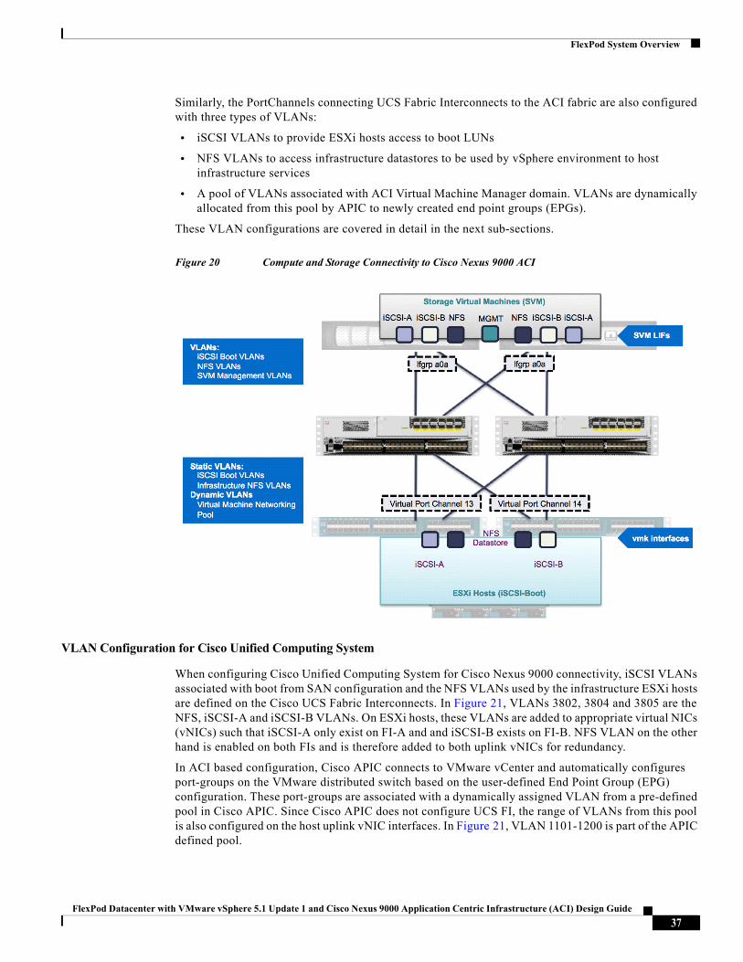
Compute and Storage Connectivity
Cisco UCS Fabric Interconnects and NetApp storage systems are connected to the Nexus 9396 switches using virtual vPC (Figure 20). The PortChannels connecting NetApp controllers to the ACI fabric are configured with three types of VLANs:
• iSCSI VLANs to provide boot LUN and direct attached storage access
• NFS VLANs to access ESXi server datastores used for hosting VMs
• Management VLANs to provide access to Tenant Storage virtual machines (SVM)
36FlexPod Datacenter with VMware vSphere 5.1 Update 1 and Cisco Nexus 9000 Application Centric Infrastructure (ACI) Design Guide
FlexPod System Overview
Similarly, the PortChannels connecting UCS Fabric Interconnects to the ACI fabric are also configured with three types of VLANs:
• iSCSI VLANs to provide ESXi hosts access to boot LUNs
• NFS VLANs to access infrastructure datastores to be used by vSphere environment to host infrastructure services
• A pool of VLANs associated with ACI Virtual Machine Manager domain. VLANs are dynamically allocated from this pool by APIC to newly created end point groups (EPGs).
These VLAN configurations are covered in detail in the next sub-sections.
Figure 20 Compute and Storage Connectivity to Cisco Nexus 9000 ACI
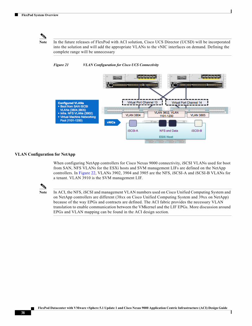
VLAN Configuration for Cisco Unified Computing System
When configuring Cisco Unified Computing System for Cisco Nexus 9000 connectivity, iSCSI VLANs associated with boot from SAN configuration and the NFS VLANs used by the infrastructure ESXi hosts are defined on the Cisco UCS Fabric Interconnects. In Figure 21, VLANs 3802, 3804 and 3805 are the NFS, iSCSI-A and iSCSI-B VLANs. On ESXi hosts, these VLANs are added to appropriate virtual NICs (vNICs) such that iSCSI-A only exist on FI-A and and iSCSI-B exists on FI-B. NFS VLAN on the other hand is enabled on both FIs and is therefore added to both uplink vNICs for redundancy.
In ACI based configuration, Cisco APIC connects to VMware vCenter and automatically configures port-groups on the VMware distributed switch based on the user-defined End Point Group (EPG) configuration. These port-groups are associated with a dynamically assigned VLAN from a pre-defined pool in Cisco APIC. Since Cisco APIC does not configure UCS FI, the range of VLANs from this pool is also configured on the host uplink vNIC interfaces. In Figure 21, VLAN 1101-1200 is part of the APIC defined pool.
37FlexPod Datacenter with VMware vSphere 5.1 Update 1 and Cisco Nexus 9000 Application Centric Infrastructure (ACI) Design Guide
FlexPod System Overview
Note In the future releases of FlexPod with ACI solution, Cisco UCS Director (UCSD) will be incorporated into the solution and will add the appropriate VLANs to the vNIC interfaces on demand. Defining the complete range will be unnecessary
Figure 21 VLAN Configuration for Cisco UCS Connectivity
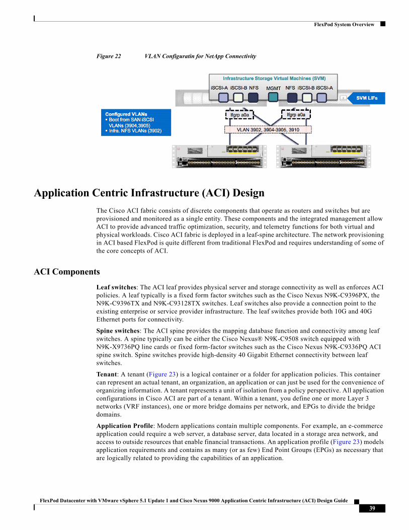
VLAN Configuration for NetApp
When configuring NetApp controllers for Cisco Nexus 9000 connectivity, iSCSI VLANs used for boot from SAN, NFS VLANs for the ESXi hosts and SVM management LIFs are defined on the NetApp controllers. In Figure 22, VLANs 3902, 3904 and 3905 are the NFS, iSCSI-A and iSCSI-B VLANs for a tenant. VLAN 3910 is the SVM management LIF.
Note In ACI, the NFS, iSCSI and management VLAN numbers used on Cisco Unified Computing System and on NetApp controllers are different (38xx on Cisco Unified Computing System and 39xx on NetApp) because of the way EPGs and contracts are defined. The ACI fabric provides the necessary VLAN translation to enable communication between the VMkernel and the LIF EPGs. More discussion around EPGs and VLAN mapping can be found in the ACI design section.
38FlexPod Datacenter with VMware vSphere 5.1 Update 1 and Cisco Nexus 9000 Application Centric Infrastructure (ACI) Design Guide
FlexPod System Overview
Figure 22 VLAN Configuratin for NetApp Connectivity
Application Centric Infrastructure (ACI) Design
The Cisco ACI fabric consists of discrete components that operate as routers and switches but are provisioned and monitored as a single entity. These components and the integrated management allow ACI to provide advanced traffic optimization, security, and telemetry functions for both virtual and physical workloads. Cisco ACI fabric is deployed in a leaf-spine architecture. The network provisioning in ACI based FlexPod is quite different from traditional FlexPod and requires understanding of some of the core concepts of ACI.
ACI Components
Leaf switches: The ACI leaf provides physical server and storage connectivity as well as enforces ACI policies. A leaf typically is a fixed form factor switches such as the Cisco Nexus N9K-C9396PX, the N9K-C9396TX and N9K-C93128TX switches. Leaf switches also provide a connection point to the existing enterprise or service provider infrastructure. The leaf switches provide both 10G and 40G Ethernet ports for connectivity.
Spine switches: The ACI spine provides the mapping database function and connectivity among leaf switches. A spine typically can be either the Cisco Nexus® N9K-C9508 switch equipped with N9K-X9736PQ line cards or fixed form-factor switches such as the Cisco Nexus N9K-C9336PQ ACI spine switch. Spine switches provide high-density 40 Gigabit Ethernet connectivity between leaf switches.
Tenant: A tenant (Figure 23) is a logical container or a folder for application policies. This container can represent an actual tenant, an organization, an application or can just be used for the convenience of organizing information. A tenant represents a unit of isolation from a policy perspective. All application configurations in Cisco ACI are part of a tenant. Within a tenant, you define one or more Layer 3 networks (VRF instances), one or more bridge domains per network, and EPGs to divide the bridge domains.
Application Profile: Modern applications contain multiple components. For example, an e-commerce application could require a web server, a database server, data located in a storage area network, and access to outside resources that enable financial transactions. An application profile (Figure 23) models application requirements and contains as many (or as few) End Point Groups (EPGs) as necessary that are logically related to providing the capabilities of an application.
39FlexPod Datacenter with VMware vSphere 5.1 Update 1 and Cisco Nexus 9000 Application Centric Infrastructure (ACI) Design Guide
FlexPod System Overview
Bridge Domain: A bridge domain represents a L2 forwarding construct within the fabric. One or more EPG can be associated with one bridge domain or subnet. A bridge domain can have one or more subnets associated with it. One or more bridge domains together form a tenant network.
End Point Group (EPG): An End Point Group (EPG) is a collection of physical and/or virtual end points that require common services and policies. An End Point Group example is a set of servers or storage LIFs on a common VLAN providing a common application function or service. While the scope of an EPG definition is much wider, in the simplest terms an EPG can be defined on a per VLAN segment basis where all the servers or VMs on a common LAN segment become part of the same EPG.
Contracts: A service contract can exist between two or more participating peer entities, such as two applications running and talking to each other behind different endpoint groups, or between providers and consumers, such as a DNS contract between a provider entity and a consumer entity. Contracts utilize filters to limit the traffic between the applications to certain ports and protocols.
Figure 23 covers relationship between the ACI elements defined above. As shown in the figure, a Tenant can contain one or more application profiles and an application profile can contain one or more end point groups. The devices in the same EPG can talk to each other without any special configuration. Devices in different EPGs can talk to each other using contracts and associated filters. A tenant can also contain one or more bridge domains and multiple application profiles and end point groups can utilize the same bridge domain.
Figure 23 ACI—Relationship Between Major Components
End Point Group (EPG) Mapping in a FlexPod Environment
In the FlexPod with ACI infrastructure, traffic is associated with an EPG in one of the two ways.
• Statically mapping a VLAN to an EPG (Figure 24)
• Associating an EPG with a Virtual Machine Manager (VMM) domain and allocating a VLAN dynamically from a pre-defined pool in APIC (Figure 25)
40FlexPod Datacenter with VMware vSphere 5.1 Update 1 and Cisco Nexus 9000 Application Centric Infrastructure (ACI) Design Guide
FlexPod System Overview
Figure 24 EPG—Static Binding to a Path
Figure 25 EPG—Virtual Machine Manager Domain Binding
The first method of statically mapping a VLAN is useful for:
• Mapping storage VLANs on NetApp Controller to storage related EPGs. These storage EPGs become the storage "providers" and are accessed by the VM and ESXi host EPGs through contracts. This mapping can be seen in Figure 28.
• Connecting ACI environment to an existing layer-2 bridge domain e.g. existing management segment. A VLAN on an out of band management switch is statically mapped to a management EPG in the common tenant to provide management services to VMs across all the tenants
• Mapping iSCSI and NFS datastores VLANs on Cisco Unified Computing System to EPGs that consume the NetApp storage EPGs defined in Step 1. Figure 28 showcases this mapping as well.
The second method of dynamically mapping a VLAN to an EPG by defining a VMM domain is used for:
• Deploying VMs in a multi-tier Application as shown in Figure 32
• Deploying iSCSI and NFS related storage access for application VMs (Figure 32)
Virtual Machine Networking
The Cisco APIC automates the networking for all virtual and physical workloads including access policies and L4-L7 services. When connected to the VMware vCenter, APIC controls the configuration of the VM switching as discussed below.
41FlexPod Datacenter with VMware vSphere 5.1 Update 1 and Cisco Nexus 9000 Application Centric Infrastructure (ACI) Design Guide
FlexPod System Overview
Virtual Machine Manager (VMM) Domains
For a VMware vCenter the creation and network configuration of the Virtual Distributed Switch (VDS) as well as set up of port groups are performed by the APIC. The APIC communicates with the VDS to publish network policies that are applied to the virtual workloads. To position an application, the application administrator deploys the VMs and places the vNICs into the appropriate port group(s) for various application tiers. A VMM domain contains multiple EPGs and hence multiple port groups.
vSwitch and Virtual Distributed Switch (VDS)
While a tenant application deployment utilizes port groups on APIC controlled VDS, some of the core functionality such as out of band management access, and iSCSI access for boot LUNs utilizes vSphere vSwitches. The resulting distribution of VMkernel ports and VM port-groups on an ESXi server is shown in Figure 26. In the Cisco UCS service profile for ESXi hosts, storage, management and VM data VLANs are defined on the vNIC interfaces used by appropriate vSwitches.
Figure 26 Application Server Design
If the management infrastructure, especially vCenter, vCenter database and AD servers are hosted on the FlexPod infrastructure, a separate set of service profiles is recommended to support infrastructure services. These infrastructure ESXi hosts will be configured with two additional vNICs tied to a dedicated storage (NFS) vSwitch as shown in Figure 27. This updated server design helps maintain access to the infrastructure services including the NFS datastores hosting the core services independent of APIC managed VDS.
42FlexPod Datacenter with VMware vSphere 5.1 Update 1 and Cisco Nexus 9000 Application Centric Infrastructure (ACI) Design Guide
FlexPod System Overview
Figure 27 Infrastructure Server Design
Onboarding Infrastructure Services
In an ACI fabric all the applications, services and connectivity between various elements are defined within the confines of tenants, application profiles, bridge domains and EPGs. The ACI constructs for core infrastructure services including an overview of the connectivity and relationship between various ACI elements is covered in Figure 28.
43FlexPod Datacenter with VMware vSphere 5.1 Update 1 and Cisco Nexus 9000 Application Centric Infrastructure (ACI) Design Guide
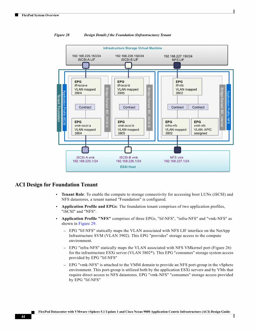
FlexPod System Overview
Figure 28 Design Details f the Foundation (Infrastructure) Tenant
ACI Design for Foundation Tenant
• Tenant Role: To enable the compute to storage connectivity for accessing boot LUNs (iSCSI) and NFS datastores, a tenant named "Foundation" is configured.
• Application Profile and EPGs: The foundation tenant comprises of two application profiles, "iSCSI" and "NFS".
• Application Profile "NFS" comprises of three EPGs, "lif-NFS", "infra-NFS" and "vmk-NFS" as shown in Figure 29.
– EPG "lif-NFS" statically maps the VLAN associated with NFS LIF interface on the NetApp Infrastructure SVM (VLAN 3902). This EPG "provides" storage access to the compute environment.
– EPG "infra-NFS" statically maps the VLAN associated with NFS VMkernel port (Figure 26) for the infrastructure ESXi server (VLAN 3802*). This EPG "consumes" storage system access provided by EPG "lif-NFS"
– EPG "vmk-NFS" is attached to the VMM domain to provide an NFS port-group in the vSphere environment. This port-group is utilized both by the application ESXi servers and by VMs that require direct access to NFS datastores. EPG "vmk-NFS" "consumes" storage access provided by EPG "lif-NFS"
44FlexPod Datacenter with VMware vSphere 5.1 Update 1 and Cisco Nexus 9000 Application Centric Infrastructure (ACI) Design Guide
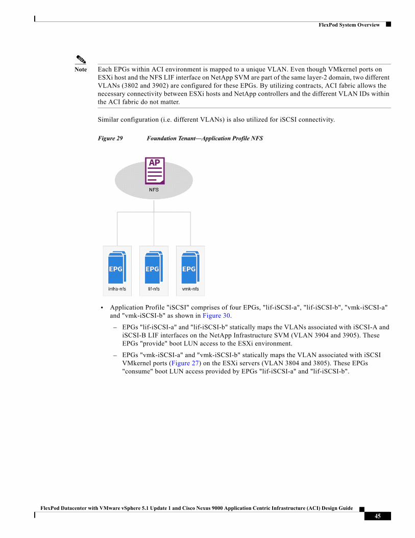
FlexPod System Overview
Note Each EPGs within ACI environment is mapped to a unique VLAN. Even though VMkernel ports on ESXi host and the NFS LIF interface on NetApp SVM are part of the same layer-2 domain, two different VLANs (3802 and 3902) are configured for these EPGs. By utilizing contracts, ACI fabric allows the necessary connectivity between ESXi hosts and NetApp controllers and the different VLAN IDs within the ACI fabric do not matter.
Similar configuration (i.e. different VLANs) is also utilized for iSCSI connectivity.
Figure 29 Foundation Tenant—Application Profile NFS
• Application Profile "iSCSI" comprises of four EPGs, "lif-iSCSI-a", "lif-iSCSI-b", "vmk-iSCSI-a" and "vmk-iSCSI-b" as shown in Figure 30.
– EPGs "lif-iSCSI-a" and "lif-iSCSI-b" statically maps the VLANs associated with iSCSI-A and iSCSI-B LIF interfaces on the NetApp Infrastructure SVM (VLAN 3904 and 3905). These EPGs "provide" boot LUN access to the ESXi environment.
– EPGs "vmk-iSCSI-a" and "vmk-iSCSI-b" statically maps the VLAN associated with iSCSI VMkernel ports (Figure 27) on the ESXi servers (VLAN 3804 and 3805). These EPGs "consume" boot LUN access provided by EPGs "lif-iSCSI-a" and "lif-iSCSI-b".
45FlexPod Datacenter with VMware vSphere 5.1 Update 1 and Cisco Nexus 9000 Application Centric Infrastructure (ACI) Design Guide
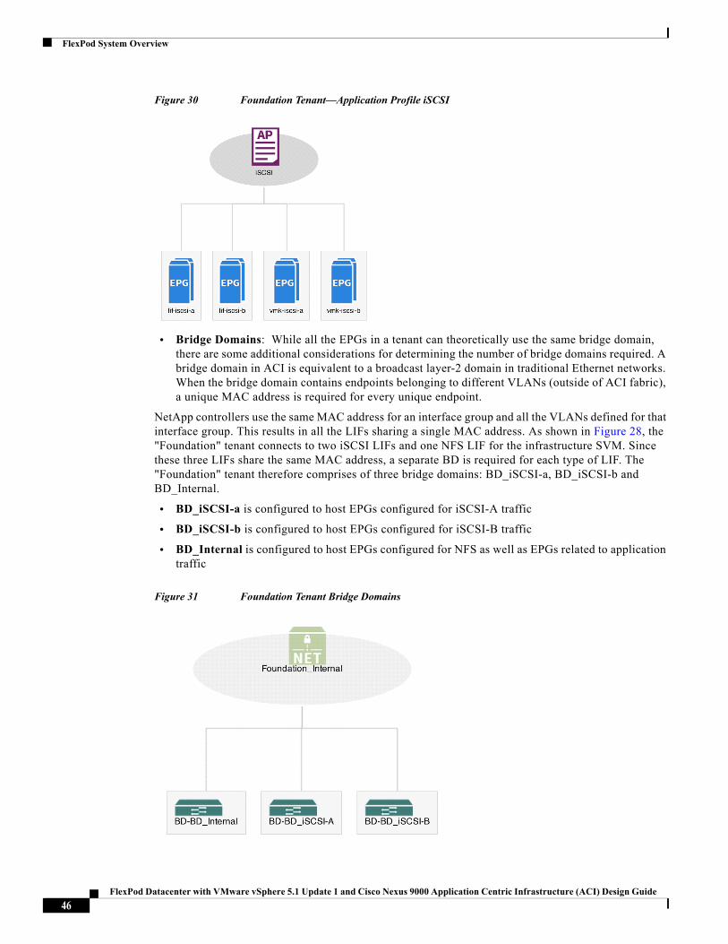
FlexPod System Overview
Figure 30 Foundation Tenant—Application Profile iSCSI
• Bridge Domains: While all the EPGs in a tenant can theoretically use the same bridge domain, there are some additional considerations for determining the number of bridge domains required. A bridge domain in ACI is equivalent to a broadcast layer-2 domain in traditional Ethernet networks. When the bridge domain contains endpoints belonging to different VLANs (outside of ACI fabric), a unique MAC address is required for every unique endpoint.
NetApp controllers use the same MAC address for an interface group and all the VLANs defined for that interface group. This results in all the LIFs sharing a single MAC address. As shown in Figure 28, the "Foundation" tenant connects to two iSCSI LIFs and one NFS LIF for the infrastructure SVM. Since these three LIFs share the same MAC address, a separate BD is required for each type of LIF. The "Foundation" tenant therefore comprises of three bridge domains: BD_iSCSI-a, BD_iSCSI-b and BD_Internal.
• BD_iSCSI-a is configured to host EPGs configured for iSCSI-A traffic
• BD_iSCSI-b is configured to host EPGs configured for iSCSI-B traffic
• BD_Internal is configured to host EPGs configured for NFS as well as EPGs related to application traffic
Figure 31 Foundation Tenant Bridge Domains
46FlexPod Datacenter with VMware vSphere 5.1 Update 1 and Cisco Nexus 9000 Application Centric Infrastructure (ACI) Design Guide
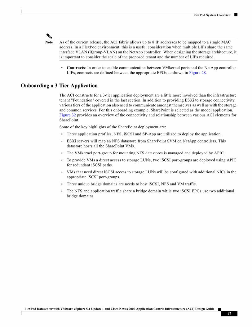
FlexPod System Overview
Note As of the current release, the ACI fabric allows up to 8 IP addresses to be mapped to a single MAC address. In a FlexPod environment, this is a useful consideration when multiple LIFs share the same interface VLAN (ifgroup-VLAN) on the NetApp controller. When designing the storage architecture, it is important to consider the scale of the proposed tenant and the number of LIFs required.
• Contracts: In order to enable communication between VMkernel ports and the NetApp controller LIFs, contracts are defined between the appropriate EPGs as shown in Figure 28.
Onboarding a 3-Tier Application
The ACI constructs for a 3-tier application deployment are a little more involved than the infrastructure tenant "Foundation" covered in the last section. In addition to providing ESXi to storage connectivity, various tiers of the application also need to communicate amongst themselves as well as with the storage and common services. For this onboarding example, SharePoint is selected as the model application. Figure 32 provides an overview of the connectivity and relationship between various ACI elements for SharePoint.
Some of the key highlights of the SharePoint deployment are:
• Three application profiles, NFS, iSCSI and SP-App are utilized to deploy the application.
• ESXi servers will map an NFS datastore from SharePoint SVM on NetApp controllers. This datastore hosts all the SharePoint VMs.
• The VMkernel port-group for mounting NFS datastores is managed and deployed by APIC.
• To provide VMs a direct access to storage LUNs, two iSCSI port-groups are deployed using APIC for redundant iSCSI paths.
• VMs that need direct iSCSI access to storage LUNs will be configured with additional NICs in the appropriate iSCSI port-groups.
• Three unique bridge domains are needs to host iSCSI, NFS and VM traffic.
• The NFS and application traffic share a bridge domain while two iSCSI EPGs use two additional bridge domains.
47FlexPod Datacenter with VMware vSphere 5.1 Update 1 and Cisco Nexus 9000 Application Centric Infrastructure (ACI) Design Guide
FlexPod System Overview
Figure 32 Design Details of the 3-Tier (SharePoint) Application
ACI Design for 3-Tier Application Tenant
• Tenant Role: To deploy different tiers of the application and to provide compute to storage connectivity, a tenant named "SharePoint" is configured.
• Application Profile and EPGs: The "SharePoint" tenant comprises of three application profiles, "SP-Application", "iSCSI" and "NFS".
– Application Profile "NFS" comprises of two EPGs, "lif-NFS" and "vmk-NFS" as shown in Figure 33.
– EPG "lif-NFS" statically maps the VLAN associated with NFS LIF on the SharePoint SVM (VLAN 3912). This EPG "provides" storage access to the compute environment.
– EPG "vmk-NFS" is attached to the VMM domain to provide an NFS port-group. in the vSphere environment. This port-group is utilized both by the SharePoint ESXi servers and by application VMs that require direct access to NFS datastores. EPG "vmk-NFS" "consumes" storage access provided by EPG "lif-NFS".
48FlexPod Datacenter with VMware vSphere 5.1 Update 1 and Cisco Nexus 9000 Application Centric Infrastructure (ACI) Design Guide
FlexPod System Overview
Figure 33 SharePoint—Application Profile NFS
• Application Profile "iSCSI" comprises of four EPGs, "lif-iSCSI-a", "lif-iSCSI-b", "vmk-iSCSI-a" and "vmk-iSCSI-b" as shown in Figure 34.
– EPGs "lif-iSCSI-a" and "lif-iSCSI-b" statically maps the VLANs associated with iSCSI-A and iSCSI-B LIF interfaces on the NetApp Infrastructure SVM (VLAN 3914 and 3915). These EPGs "provide" boot LUN access to VMs.
– EPGs "vmk-iSCSI-a" and "vmk-iSCSI-b" are attached to the VMM domain to provide iSCSI port-groups. These port-groups are utilized by VMs that require direct access to storage LUNs and "consume" storage access provided by "lif-iSCSI-A" and "lif-iSCSI-B".
Figure 34 SharePoint—Application Profile iSCSI
49FlexPod Datacenter with VMware vSphere 5.1 Update 1 and Cisco Nexus 9000 Application Centric Infrastructure (ACI) Design Guide
FlexPod System Overview
• Application Profile "SP-Application" comprises of four EPGs, "SP-Web", "SP-App", "SP-DB" and "SP-External"
– EPG "SP-Web" is attached to the VMM domain and provides a port-group on VDS to connect the SharePoint web servers.
– EPG "SP-App" is attached to the VMM domain and provides a port-group on VDS to connect the SharePoint Application servers.
– EPG "SP-DB" is attached to the VMM domain and provides a port-group on VDS to connect the SharePoint Database servers.
– EPG "SP-Common" is attached to the VMM domain and provides a port-group on VDS for hosting VMs providing common services for various application tiers.
– EPGs "SP-External" is attached to the VMM domain and provides a port-group that allows SharePoint application to connect to existing datacenter infrastructure. Any VM connected to this port-group will be able to route to infrastructure outside ACI domain.
Figure 35 SharePoint—SharePoint Application Profile
• Bridge Domain: The "SharePoint" tenant comprises of four bridge domains, BD_iSCSI-a, BD_iSCSI-b, BD_Internal and BD_External.
– BD_iSCSI-a is configured to host EPGs configured for iSCSI-A traffic
– BD_iSCSI-b is configured to host EPGs configured for iSCSI-B traffic
– BD_Internal is configured to host EPGs configured for NFS as well as EPGs related to application traffic
– BD_External is configured to host EPGs configured for connectivity to the external infrastructure.
• Contracts: In order to enable communication between VMkernel ports and the NetApp controller LIFs as well as communication between various application tiers, contracts are defined between the relevant EPGs as shown in Figure 32.
50FlexPod Datacenter with VMware vSphere 5.1 Update 1 and Cisco Nexus 9000 Application Centric Infrastructure (ACI) Design Guide
FlexPod System Overview
Common Services and Storage Management
Accessing Common Services
Cisco ACI fabric provides a predefined tenant (named "common") to host common services i.e. services shared by various tenants. The policies defined in the "common" tenant are usable by all the tenants. In addition to the locally defined contracts, all the tenants in ACI fabric have access to the contracts defined in the "common" tenant. To provide application servers access to common services such as Active Directory (AD), Domain Name Services (DNS), management and monitoring software etc., these services VMs are placed in the common tenant and appropriate inter-tenant contracts are defined.
In the FlexPod environment, access to common services is provided as shown in Figure 36. To provide this access:
• A common services segment is defined where common services VMs connect using a secondary NIC. A separate services segment ensures that the access from the tenant VMs is limited to only common services
• The EPG for common services segment is defined in the "common" tenant
• The tenant VMs access the common management segment by defining contracts between application tenant and "common" tenant
• The contract filters are configured to only allow specific services related ports
Figure 36 shows both "provider" EPG "Management-Access" in the tenant "common" and the consumer EPGs "SP-Web", "SP-App" and "SP-DB" in tenant "SharePoint".
Figure 36 Common Services and Storage Management
51FlexPod Datacenter with VMware vSphere 5.1 Update 1 and Cisco Nexus 9000 Application Centric Infrastructure (ACI) Design Guide
FlexPod System Overview
Accessing SVM Management
Some applications such as NetApp Snap Drive require direct connectivity from application (SharePoint, Exchange etc.) VMs to the management LIF on the tenant SVM. To provide this connectivity securely, a separate VLAN is dedicated for each tenant to define the management LIF. This VLAN is then statically mapped to an EPG in the application tenant as shown in Figure 36. Application VMs can access this LIF by defining contracts.
Note If the application tenant (such as SharePoint) contains mappings for any other LIFs (iSCSI, NFS etc.), a separate bridge domain is required for SVM management LIF because of the overlapping LIF MAC addresses
NetApp SnapManager and Snapdrive with Cisco ACI
NetApp SnapDrive and the SnapManager portfolio of products greatly simplify storage provisioning and the backup of application data. In this design, the SVM management LIF is placed on a VLAN within the application tenant and a contract is built linking the application VM's management interface with the SVM management LIF. This interaction takes place through HTTPS on TCP port 443 by default.
LUN provisioning is also handled by the interaction of SnapDrive and the SVM management LIF. If VMware RDM LUNs are being used for the application data, SnapDrive must interact with VMware vCenter to perform the RDM LUN mapping. The Snapshot copy management of application VMDK disks on NFS or VMFS datastores is handled by SnapDrive interacting with NetApp VSC. In this design, secondary network interfaces on the VMware vCenter and VSC VMs are placed in the ACI common tenant. Then application VMs from multiple tenants can consume contracts to access the core vCenter and VSC VMs simultaneously while not allowing any communication between tenants. The vCenter interaction takes place through HTTPS on TCP port 443 by default, while the VSC interaction takes place on TCP port 8043 by default. Specific contracts with only these TCP ports can be configured, and the default ports used can be changed.
Using these ACI capabilities with the Role-Based Access Control (RBAC) capabilities of vCenter, NetApp VSC, and NetApp clustered Data ONTAP allows multiple-tenant administrators and individual-application administrators to simultaneously and securely provision and back up application data storage while taking advantage of the NetApp storage efficiency capabilities.
FlexPod Connectivity to Existing Infrastructure
In order to connect ACI fabric to existing infrastructure, the leaf nodes are connected to a pair of core infrastructure routers/switches. In this design, a Cisco Nexus 7000 was configured as the core router. Figure 37 shows the connectivity details including tenant virtual routing and forwarding (VRF) mappings. The network shown below covers connectivity from two different tenants to highlight traffic segregation.
52FlexPod Datacenter with VMware vSphere 5.1 Update 1 and Cisco Nexus 9000 Application Centric Infrastructure (ACI) Design Guide
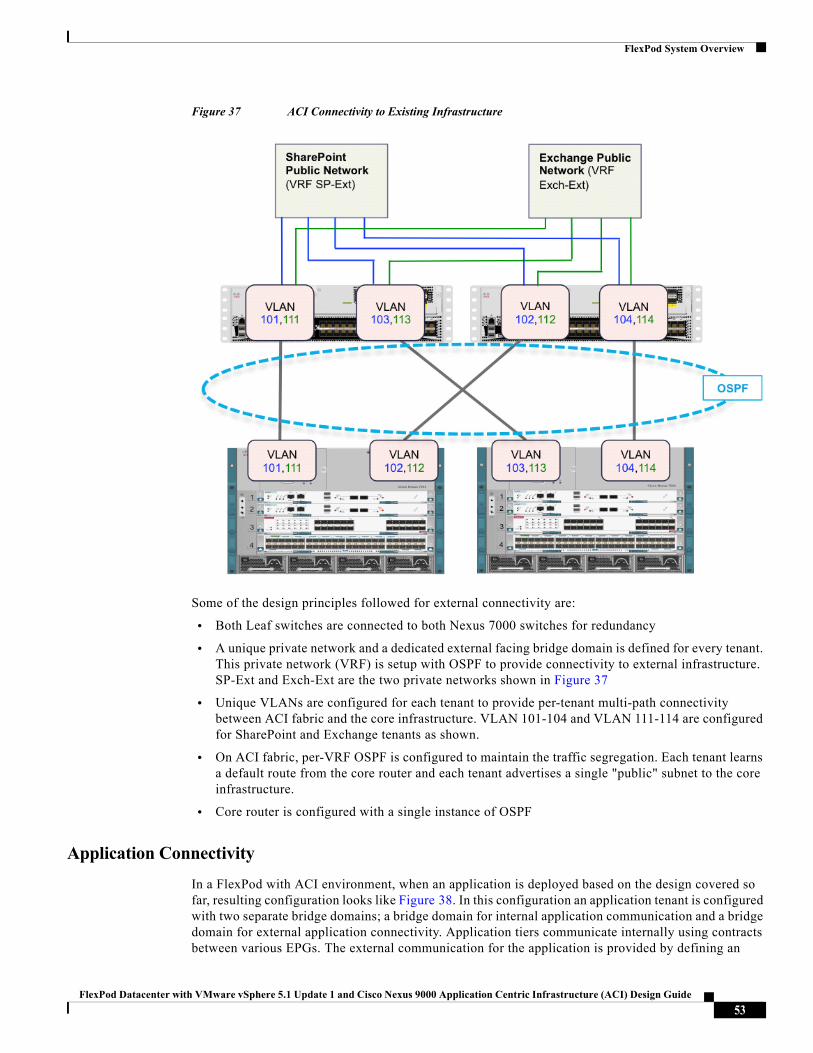
FlexPod System Overview
Figure 37 ACI Connectivity to Existing Infrastructure
Some of the design principles followed for external connectivity are:
• Both Leaf switches are connected to both Nexus 7000 switches for redundancy
• A unique private network and a dedicated external facing bridge domain is defined for every tenant. This private network (VRF) is setup with OSPF to provide connectivity to external infrastructure. SP-Ext and Exch-Ext are the two private networks shown in Figure 37
• Unique VLANs are configured for each tenant to provide per-tenant multi-path connectivity between ACI fabric and the core infrastructure. VLAN 101-104 and VLAN 111-114 are configured for SharePoint and Exchange tenants as shown.
• On ACI fabric, per-VRF OSPF is configured to maintain the traffic segregation. Each tenant learns a default route from the core router and each tenant advertises a single "public" subnet to the core infrastructure.
• Core router is configured with a single instance of OSPF
Application Connectivity
In a FlexPod with ACI environment, when an application is deployed based on the design covered so far, resulting configuration looks like Figure 38. In this configuration an application tenant is configured with two separate bridge domains; a bridge domain for internal application communication and a bridge domain for external application connectivity. Application tiers communicate internally using contracts between various EPGs. The external communication for the application is provided by defining an
53FlexPod Datacenter with VMware vSphere 5.1 Update 1 and Cisco Nexus 9000 Application Centric Infrastructure (ACI) Design Guide
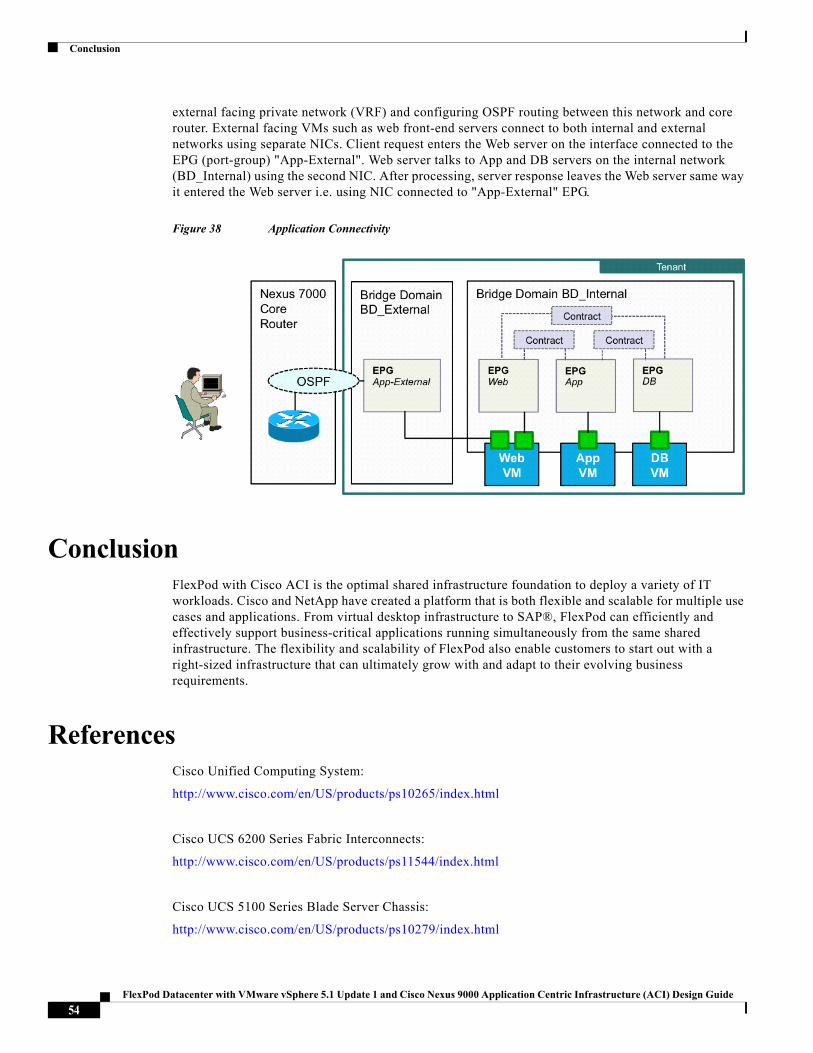
Conclusion
external facing private network (VRF) and configuring OSPF routing between this network and core router. External facing VMs such as web front-end servers connect to both internal and external networks using separate NICs. Client request enters the Web server on the interface connected to the EPG (port-group) "App-External". Web server talks to App and DB servers on the internal network (BD_Internal) using the second NIC. After processing, server response leaves the Web server same way it entered the Web server i.e. using NIC connected to "App-External" EPG.
Figure 38 Application Connectivity
ConclusionFlexPod with Cisco ACI is the optimal shared infrastructure foundation to deploy a variety of IT workloads. Cisco and NetApp have created a platform that is both flexible and scalable for multiple use cases and applications. From virtual desktop infrastructure to SAP®, FlexPod can efficiently and effectively support business-critical applications running simultaneously from the same shared infrastructure. The flexibility and scalability of FlexPod also enable customers to start out with a right-sized infrastructure that can ultimately grow with and adapt to their evolving business requirements.
ReferencesCisco Unified Computing System:
http://www.cisco.com/en/US/products/ps10265/index.html
Cisco UCS 6200 Series Fabric Interconnects:
http://www.cisco.com/en/US/products/ps11544/index.html
Cisco UCS 5100 Series Blade Server Chassis:
http://www.cisco.com/en/US/products/ps10279/index.html
54FlexPod Datacenter with VMware vSphere 5.1 Update 1 and Cisco Nexus 9000 Application Centric Infrastructure (ACI) Design Guide
References
Cisco UCS B-Series Blade Servers:
http://www.cisco.com/en/US/partner/products/ps10280/index.html
Cisco UCS Adapters:
http://www.cisco.com/en/US/products/ps10277/prod_module_series_home.html
Cisco UCS Manager:
http://www.cisco.com/en/US/products/ps10281/index.html
Cisco Nexus 9000 Series Switches:
http://www.cisco.com/c/en/us/support/switches/nexus-9000-series-switches/tsd-products-support-series-home.html
Cisco Application Centric Infrastructure:
http://www.cisco.com/c/en/us/solutions/data-center-virtualization/application-centric-infrastructure/index.html
VMware vCenter Server:
http://www.vmware.com/products/vcenter-server/overview.html
VMware vSphere:
http://www.vmware.com/products/datacenter-virtualization/vsphere/index.html
NetApp Data ONTAP:
http://www.netapp.com/us/products/platform-os/data-ontap-8/index.aspx.
NetApp FAS8000:
http://www.netapp.com/us/products/storage-systems/fas8000/
NetApp OnCommand:
http://www.netapp.com/us/products/management-software/
NetApp VSC:
http://www.netapp.com/us/products/management-software/vsc/
NetApp SnapManager:
http://www.netapp.com/us/products/management-software/snapmanager/
55FlexPod Datacenter with VMware vSphere 5.1 Update 1 and Cisco Nexus 9000 Application Centric Infrastructure (ACI) Design Guide
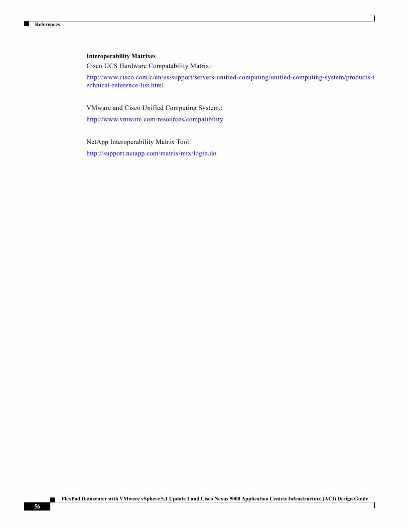
References
Interoperability Matrixes
Cisco UCS Hardware Compatability Matrix:
http://www.cisco.com/c/en/us/support/servers-unified-computing/unified-computing-system/products-technical-reference-list.html
VMware and Cisco Unified Computing System,:
http://www.vmware.com/resources/compatibility
NetApp Interoperability Matrix Tool:
http://support.netapp.com/matrix/mtx/login.do
56FlexPod Datacenter with VMware vSphere 5.1 Update 1 and Cisco Nexus 9000 Application Centric Infrastructure (ACI) Design Guide