Embed Size (px)
Citation preview
FlexPod Datacenter with Cisco Secure Enclaves
Last Updated: May 15, 2014
Building Architectures to Solve Business Problems
2
About the Authors
re his current role, he supported and administered Nortel's worldwide training network structure. John holds a Master's degree in computer engineering from Clemson University.
t, Solutions Architect, Infrastructure and Cloud Engineering, NetApp
is a Solutions Architect in the NetApp Infrastructure and Cloud Engineering team. She architecture, implementation, compatibility, and security of innovative vendor develop competitive and high-performance end-to-end cloud solutions for customers. her career in 2006 at Nortel as an interoperability test engineer, testing customer roperability for certification. Lindsey has her Bachelors of Science degree in Computer d her Masters of Science in Information Security from East Carolina University.
About the AuthorsChris O'Brien, Technical Marketing Manager, Server Access Virtualization Business Unit, Cisco Systems
Chris O'Brien is currently focused on developing infrastructure best practices and solutions that are designed, tested, and documented to facilitate and improve customer deployments. Previously, O'Brien was an application developer and has worked in the IT industry for more than 15 years.
John George, Reference Architect, Infrastructure and Cloud Engineering, NetApp
John George is a Reference Architect in the NetApp Infrastructure and Cloud Engineering team and is focused on developing, validating, and supporting cloud infrastructure solutions that include NetApp products. Befoand VPN infra
Lindsey Stree
Lindsey Streetfocuses on thetechnologies toLindsey startedequipment inteNetworking an
3
4About Cisco Validated Desig
About the Authors
n (CVD) Program
IM ALL WARRANTIES, INCLUDING, WITHOUT LIMITATION, THE WARRANTY OF
ILITY, FITNESS FOR A PARTICULAR PURPOSE AND NONINFRINGEMENT OR ARISING
SE OF DEALING, USAGE, OR TRADE PRACTICE. IN NO EVENT SHALL CISCO OR ITS
LIABLE FOR ANY INDIRECT, SPECIAL, CONSEQUENTIAL, OR INCIDENTAL DAMAGES,
ITHOUT LIMITATION, LOST PROFITS OR LOSS OR DAMAGE TO DATA ARISING OUT OF
ABILITY TO USE THE DESIGNS, EVEN IF CISCO OR ITS SUPPLIERS HAVE BEEN ADVISED
IBILITY OF SUCH DAMAGES.
ARE SUBJECT TO CHANGE WITHOUT NOTICE. USERS ARE SOLELY RESPONSIBLE FOR
TION OF THE DESIGNS. THE DESIGNS DO NOT CONSTITUTE THE TECHNICAL OR
SSIONAL ADVICE OF CISCO, ITS SUPPLIERS OR PARTNERS. USERS SHOULD CONSULT
CHNICAL ADVISORS BEFORE IMPLEMENTING THE DESIGNS. RESULTS MAY VARY
N FACTORS NOT TESTED BY CISCO.
Cisco Eos, Cisco Lumin, Cisco Nexus, Cisco StadiumVision, Cisco TelePresence, Cisco
co logo, DCE, and Welcome to the Human Network are trademarks; Changing the Way We
y, and Learn and Cisco Store are service marks; and Access Registrar, Aironet, AsyncOS,
eeting To You, Catalyst, CCDA, CCDP, CCIE, CCIP, CCNA, CCNP, CCSP, CCVP, Cisco, the
Internetwork Expert logo, Cisco IOS, Cisco Press, Cisco Systems, Cisco Systems Capital,
ems logo, Cisco Unity, Collaboration Without Limitation, EtherFast, EtherSwitch, Event Cen-
ollow Me Browsing, FormShare, GigaDrive, HomeLink, Internet Quotient, IOS, iPhone,
onPort, the IronPort logo, LightStream, Linksys, MediaTone, MeetingPlace, MeetingPlace
MGX, Networkers, Networking Academy, Network Registrar, PCNow, PIX, PowerPanels,
criptShare, SenderBase, SMARTnet, Spectrum Expert, StackWise, The Fastest Way to
nternet Quotient, TransPath, WebEx, and the WebEx logo are registered trademarks of
, Inc. and/or its affiliates in the United States and certain other countries.
arks mentioned in this document or website are the property of their respective owners.
word partner does not imply a partnership relationship between Cisco and any other com-
Systems, Inc. All rights reserved
About Cisco Validated Design (CVD) Program
The CVD program consists of systems and solutions designed, tested, and documented to facilitate
faster, more reliable, and more predictable customer deployments. For more information visit
http://www.cisco.com/go/designzone.
ALL DESIGNS, SPECIFICATIONS, STATEMENTS, INFORMATION, AND RECOMMENDATIONS (COLLEC-
TIVELY, "DESIGNS") IN THIS MANUAL ARE PRESENTED "AS IS," WITH ALL FAULTS. CISCO AND ITS SUP-
PLIERS DISCLA
MERCHANTAB
FROM A COUR
SUPPLIERS BE
INCLUDING, W
THE USE OR IN
OF THE POSS
THE DESIGNS
THEIR APPLICA
OTHER PROFE
THEIR OWN TE
DEPENDING O
CCDE, CCENT,
WebEx, the Cis
Work, Live, Pla
Bringing the M
Cisco Certified
the Cisco Syst
ter, Fast Step, F
iQuick Study, Ir
Chime Sound,
ProConnect, S
Increase Your I
Cisco Systems
All other tradem
The use of the
pany. (0809R)
© 2014 Cisco
FlexPod Datacenter with Cisco Secure Enclaves
OverviewThe increased scrutiny on security is being driven by the evolving trends of mobility, cloud computing, and advanced targeted attacks. More than the attacks themselves, a major consideration is the change in what defines a network, which goes beyond traditional walls and includes data centers, endpoints, virtual and mobile to make up the extended network.
Today most converged infrastructures are designed to meet performance and function requirements with little or no attention to security. Furthermore, the movement toward optimal use of IT resources through virtualization has resulted in an environment in which the true and implied security accorded by physical separation has essentially vanished. System consolidation efforts have also accelerated the movement toward co-hosting on converged platforms, and the likelihood of compromise is increased in a highly shared environment. This situation presents a need for enhanced security and an opportunity to create a framework and platform that instills trust.
The FlexPod Data Center with Cisco Secure Enclaves solution is a threat-centric approach to security allowing customers to address the full attack continuum, before during and after the attack on a standard platform with a consistent approach. The solution is based on the FlexPod Data Center integrated system and augmented with services to address business, compliance and application requirements. The FlexPod Data Center with Cisco Secure Enclaves is a standard approach to delivering a flexible, functional and secure application environment that can be readily automated.
Solution Components
FlexPod Datacenter with Cisco Secure Enclaves uses the FlexPod Data Center configuration as its foundation. The FlexPod Data Center is an integrated infrastructure solution from Cisco and NetApp with validated designs that expedite IT infrastructure and application deployment, while simultaneously reducing cost, complexity, and project risk. FlexPod Data Center consists of Cisco Nexus Networking, Cisco Unified Computing System™ (Cisco UCS®), NetApp FAS Series storage systems. One especially significant benefit of the FlexPod architecture is the ability to customize or "flex" the environment to suit a customer's requirements, this includes the hardware previously mentioned as well as operating systems or hypervisors it supports.
Audience
The Cisco Secure Enclaves design extends the FlexPod infrastructure by using the abilities inherit to the integrated system and augmenting this functionality with services to address the specific business and application requirements of the enterprise. These functional requirements promote uniqueness and innovation in the FlexPod, augmenting the original FlexPod design to support these prerequisites. The result is a region, or enclave, and more likely multiple enclaves, in the FlexPod built to address the unique workload activities and business objectives of an organization.
FlexPod Data Center with Cisco Secure Enclaves is developed using the following technologies:
• FlexPod Data Center from Cisco and NetApp
• VMware vSphere
• Cisco Adaptive Security Appliance (ASA)
• Cisco NetFlow Generation Appliance (NGA)
• Cisco Virtual Security Gateway (VSG)
• Cisco Identity Services Engine (ISE)
• Cisco Network Analysis Module
• Cisco UCS Director
• Lancope StealthWatch System
Note The FlexPod solution is hypervisor agnostic. Please go to the Reference Section of this document for URLs providing more details about the individual components of the solution.
AudienceThis document describes the architecture and deployment procedures of a secure FlexPod Data Center infrastructure enabled with Cisco and NetApp technologies. The intended audience for this document includes but is not limited to sales engineers, field consultants, professional services, IT managers, partner engineering, and customers interested in making security an integral part of their FlexPod infrastructure.
FlexPod Data Center with Cisco Secure Enclaves
FlexPod Data Center with Cisco Secure Enclaves Overview
The FlexPod Data Center with Cisco Secure Enclaves is a standardized approach to the integration of security services with a FlexPod Data Center based infrastructure. The design enables features inherit to the FlexPod platform and calls for its extension through dedicated physical or virtual appliance implementations. The main design objective is to help ensure that applications in this environment meet their subscribed service-level agreements (SLAs), including confidentiality requirements, by using the validated FlexPod infrastructure and the security additions it can readily support. The secure enclave framework allows an organization to adapt the FlexPod shared infrastructure to meet the disparate needs of users and applications based on their specific requirements.
6FlexPod Datacenter with Cisco Secure Enclaves
FlexPod Data Center with Cisco Secure Enclaves
Components of FlexPod Data Center with Cisco Secure Enclaves
FlexPod Data Center
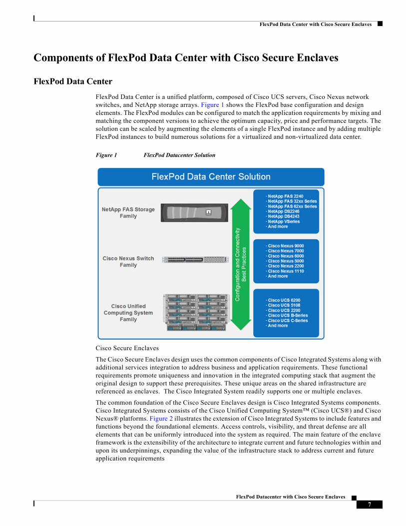
FlexPod Data Center is a unified platform, composed of Cisco UCS servers, Cisco Nexus network switches, and NetApp storage arrays. Figure 1 shows the FlexPod base configuration and design elements. The FlexPod modules can be configured to match the application requirements by mixing and matching the component versions to achieve the optimum capacity, price and performance targets. The solution can be scaled by augmenting the elements of a single FlexPod instance and by adding multiple FlexPod instances to build numerous solutions for a virtualized and non-virtualized data center.
Figure 1 FlexPod Datacenter Solution
Cisco Secure Enclaves
The Cisco Secure Enclaves design uses the common components of Cisco Integrated Systems along with additional services integration to address business and application requirements. These functional requirements promote uniqueness and innovation in the integrated computing stack that augment the original design to support these prerequisites. These unique areas on the shared infrastructure are referenced as enclaves. The Cisco Integrated System readily supports one or multiple enclaves.
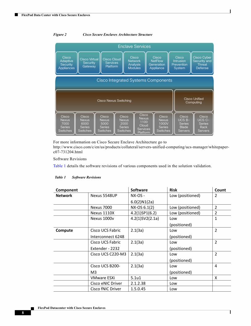
The common foundation of the Cisco Secure Enclaves design is Cisco Integrated Systems components. Cisco Integrated Systems consists of the Cisco Unified Computing System™ (Cisco UCS®) and Cisco Nexus® platforms. Figure 2 illustrates the extension of Cisco Integrated Systems to include features and functions beyond the foundational elements. Access controls, visibility, and threat defense are all elements that can be uniformly introduced into the system as required. The main feature of the enclave framework is the extensibility of the architecture to integrate current and future technologies within and upon its underpinnings, expanding the value of the infrastructure stack to address current and future application requirements
7FlexPod Datacenter with Cisco Secure Enclaves
FlexPod Data Center with Cisco Secure Enclaves
Figure 2 Cisco Secure Enclaves Architecture Structure
For more information on Cisco Secure Enclave Architecture go to http://www.cisco.com/c/en/us/products/collateral/servers-unified-computing/ucs-manager/whitepaper-c07-731204.html
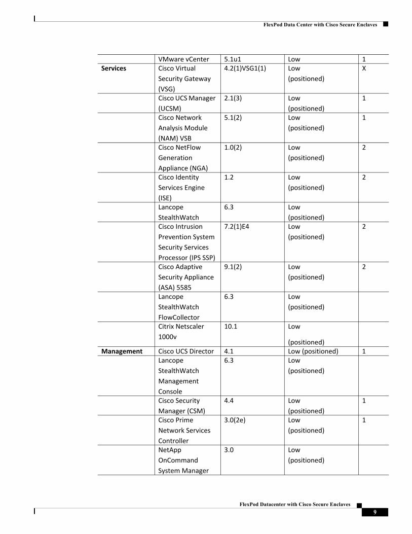
Software Revisions
Table 1 details the software revisions of various components used in the solution validation.
Table 1 Software Revisions
Component Software Risk CountNetwork Nexus 5548UP NX-OS -
6.0(2)N1(2a)Low (positioned) 2
Nexus 7000 NX-OS 6.1(2) Low (positioned) 2Nexus 1110X 4.2(1)SP1(6.2) Low (positioned) 2Nexus 1000v 4.2(1)SV2(2.1a) Low
(positioned)1
Compute Cisco UCS Fabric Interconnect 6248
2.1(3a) Low (positioned)
2
Cisco UCS Fabric Extender - 2232
2.1(3a) Low (positioned)
2
Cisco UCS C220-M3 2.1(3a) Low (positioned)
2
Cisco UCS B200- M3
2.1(3a) Low (positioned)
4
VMware ESXi 5.1u1 Low XCisco eNIC Driver 2.1.2.38 LowCisco fNIC Driver 1.5.0.45 Low
8FlexPod Datacenter with Cisco Secure Enclaves
FlexPod Data Center with Cisco Secure Enclaves
VMware vCenter 5.1u1 Low 1Services Cisco Virtual
Security Gateway (VSG)
4.2(1)VSG1(1) Low (positioned)
X
Cisco UCS Manager (UCSM)
2.1(3) Low (positioned)
1
Cisco Network Analysis Module (NAM) VSB
5.1(2) Low (positioned)
1
Cisco NetFlow Generation Appliance (NGA)
1.0(2) Low (positioned)
2
Cisco Identity Services Engine (ISE)
1.2 Low (positioned)
2
Lancope StealthWatch
6.3 Low (positioned)
Cisco Intrusion Prevention System Security Services Processor (IPS SSP)
7.2(1)E4 Low (positioned)
2
Cisco Adaptive Security Appliance (ASA) 5585
9.1(2) Low (positioned)
2
Lancope StealthWatch FlowCollector
6.3 Low (positioned)
Citrix Netscaler 1000v
10.1 Low
(positioned)Management Cisco UCS Director 4.1 Low (positioned) 1
Lancope StealthWatch Management Console
6.3 Low (positioned)
Cisco Security Manager (CSM)
4.4 Low (positioned)
1
Cisco Prime Network Services Controller
3.0(2e) Low (positioned)
1
NetApp OnCommand System Manager
3.0 Low (positioned)
9FlexPod Datacenter with Cisco Secure Enclaves
FlexPod Data Center with Cisco Secure Enclaves Architecture and Design
FlexPod Data Center with Cisco Secure Enclaves Architecture and Design
FlexPod Topology
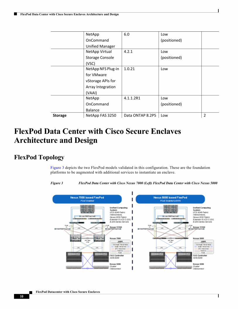
Figure 3 depicts the two FlexPod models validated in this configuration. These are the foundation platforms to be augmented with additional services to instantiate an enclave.
Figure 3 FlexPod Data Center with Cisco Nexus 7000 (Left) FlexPod Data Center with Cisco Nexus 5000
NetApp OnCommand Unified Manager
6.0 Low (positioned)
NetApp Virtual Storage Console (VSC)
4.2.1 Low (positioned)
NetApp NFS Plug-in for VMware vStorage APIs for Array Integration (VAAI)
1.0.21 Low
NetApp OnCommand Balance
4.1.1.2R1 Low (positioned)
Storage NetApp FAS 3250 Data ONTAP 8.2P5 Low 2
10FlexPod Datacenter with Cisco Secure Enclaves
FlexPod Data Center with Cisco Secure Enclaves Architecture and Design
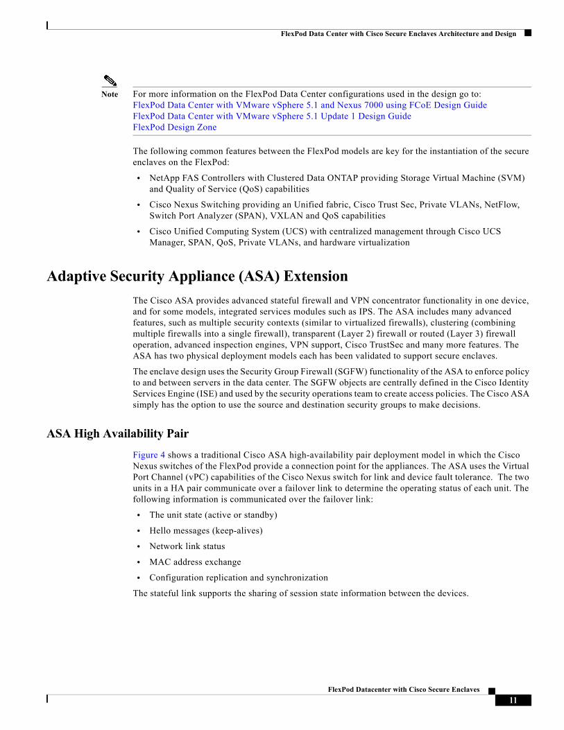
Note For more information on the FlexPod Data Center configurations used in the design go to: FlexPod Data Center with VMware vSphere 5.1 and Nexus 7000 using FCoE Design Guide FlexPod Data Center with VMware vSphere 5.1 Update 1 Design Guide FlexPod Design Zone
The following common features between the FlexPod models are key for the instantiation of the secure enclaves on the FlexPod:
• NetApp FAS Controllers with Clustered Data ONTAP providing Storage Virtual Machine (SVM) and Quality of Service (QoS) capabilities
• Cisco Nexus Switching providing an Unified fabric, Cisco Trust Sec, Private VLANs, NetFlow, Switch Port Analyzer (SPAN), VXLAN and QoS capabilities
• Cisco Unified Computing System (UCS) with centralized management through Cisco UCS Manager, SPAN, QoS, Private VLANs, and hardware virtualization
Adaptive Security Appliance (ASA) Extension
The Cisco ASA provides advanced stateful firewall and VPN concentrator functionality in one device, and for some models, integrated services modules such as IPS. The ASA includes many advanced features, such as multiple security contexts (similar to virtualized firewalls), clustering (combining multiple firewalls into a single firewall), transparent (Layer 2) firewall or routed (Layer 3) firewall operation, advanced inspection engines, VPN support, Cisco TrustSec and many more features. The ASA has two physical deployment models each has been validated to support secure enclaves.
The enclave design uses the Security Group Firewall (SGFW) functionality of the ASA to enforce policy to and between servers in the data center. The SGFW objects are centrally defined in the Cisco Identity Services Engine (ISE) and used by the security operations team to create access policies. The Cisco ASA simply has the option to use the source and destination security groups to make decisions.
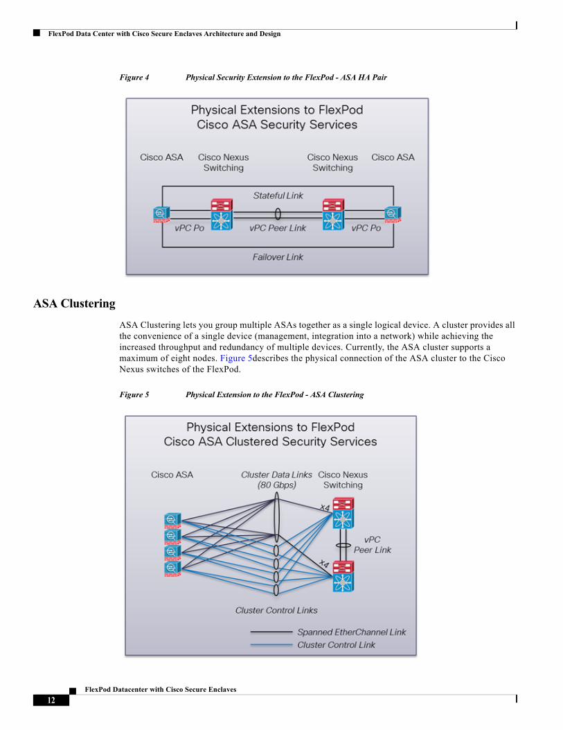
ASA High Availability Pair
Figure 4 shows a traditional Cisco ASA high-availability pair deployment model in which the Cisco Nexus switches of the FlexPod provide a connection point for the appliances. The ASA uses the Virtual Port Channel (vPC) capabilities of the Cisco Nexus switch for link and device fault tolerance. The two units in a HA pair communicate over a failover link to determine the operating status of each unit. The following information is communicated over the failover link:
• The unit state (active or standby)
• Hello messages (keep-alives)
• Network link status
• MAC address exchange
• Configuration replication and synchronization
The stateful link supports the sharing of session state information between the devices.
11FlexPod Datacenter with Cisco Secure Enclaves
FlexPod Data Center with Cisco Secure Enclaves Architecture and Design
Figure 4 Physical Security Extension to the FlexPod - ASA HA Pair
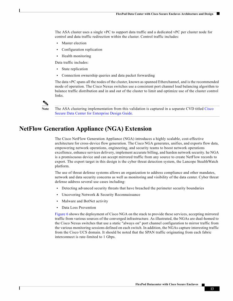
ASA Clustering
ASA Clustering lets you group multiple ASAs together as a single logical device. A cluster provides all the convenience of a single device (management, integration into a network) while achieving the increased throughput and redundancy of multiple devices. Currently, the ASA cluster supports a maximum of eight nodes. Figure 5describes the physical connection of the ASA cluster to the Cisco Nexus switches of the FlexPod.
Figure 5 Physical Extension to the FlexPod - ASA Clustering
12FlexPod Datacenter with Cisco Secure Enclaves
FlexPod Data Center with Cisco Secure Enclaves Architecture and Design
The ASA cluster uses a single vPC to support data traffic and a dedicated vPC per cluster node for control and data traffic redirection within the cluster. Control traffic includes:
• Master election
• Configuration replication
• Health monitoring
Data traffic includes:
• State replication
• Connection ownership queries and data packet forwarding
The data vPC spans all the nodes of the cluster, known as spanned Etherchannel, and is the recommended mode of operation. The Cisco Nexus switches use a consistent port channel load balancing algorithm to balance traffic distribution and in and out of the cluster to limit and optimize use of the cluster control links.
Note The ASA clustering implementation from this validation is captured in a separate CVD titled Cisco Secure Data Center for Enterprise Design Guide.
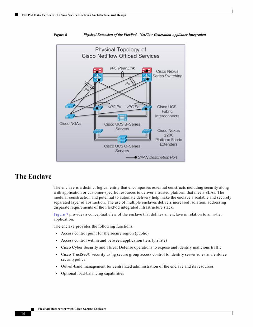
NetFlow Generation Appliance (NGA) Extension
The Cisco NetFlow Generation Appliance (NGA) introduces a highly scalable, cost-effective architecture for cross-device flow generation. The Cisco NGA generates, unifies, and exports flow data, empowering network operations, engineering, and security teams to boost network operations excellence, enhance services delivery, implement accurate billing, and harden network security. he NGA is a promiscuous device and can accept mirrored traffic from any source to create NetFlow records to export. The export target in this design is the cyber threat detection system, the Lancope StealthWatch platform.
The use of threat defense systems allows an organization to address compliance and other mandates, network and data security concerns as well as monitoring and visibility of the data center. Cyber threat defense address several use cases including:
• Detecting advanced security threats that have breached the perimeter security boundaries
• Uncovering Network & Security Reconnaissance
• Malware and BotNet activity
• Data Loss Prevention
Figure 6 shows the deployment of Cisco NGA on the stack to provide these services, accepting mirrored traffic from various sources of the converged infrastructure. As illustrated, the NGAs are dual-homed to the Cisco Nexus switches that use a static "always on" port channel configuration to mirror traffic from the various monitoring sessions defined on each switch. In addition, the NGAs capture interesting traffic from the Cisco UCS domain. It should be noted that the SPAN traffic originating from each fabric interconnect is rate-limited to 1 Gbps.
13FlexPod Datacenter with Cisco Secure Enclaves
FlexPod Data Center with Cisco Secure Enclaves Architecture and Design
Figure 6 Physical Extension of the FlexPod - NetFlow Generation Appliance Integration
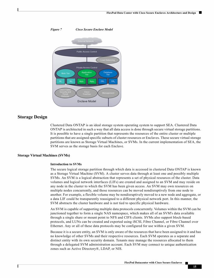
The Enclave
The enclave is a distinct logical entity that encompasses essential constructs including security along with application or customer-specific resources to deliver a trusted platform that meets SLAs. The modular construction and potential to automate delivery help make the enclave a scalable and securely separated layer of abstraction. The use of multiple enclaves delivers increased isolation, addressing disparate requirements of the FlexPod integrated infrastructure stack.
Figure 7 provides a conceptual view of the enclave that defines an enclave in relation to an n-tier application.
The enclave provides the following functions:
• Access control point for the secure region (public)
• Access control within and between application tiers (private)
• Cisco Cyber Security and Threat Defense operations to expose and identify malicious traffic
• Cisco TrustSec® security using secure group access control to identify server roles and enforce securitypolicy
• Out-of-band management for centralized administration of the enclave and its resources
• Optional load-balancing capabilities
14FlexPod Datacenter with Cisco Secure Enclaves
FlexPod Data Center with Cisco Secure Enclaves Architecture and Design
Figure 7 Cisco Secure Enclave Model
Storage Design
Clustered Data ONTAP is an ideal storage system operating system to support SEA. Clustered Data ONTAP is architected in such a way that all data access is done through secure virtual storage partitions. It is possible to have a single partition that represents the resources of the entire cluster or multiple partitions that are assigned specific subsets of cluster resources or Enclaves. These secure virtual storage partitions are known as Storage Virtual Machines, or SVMs. In the current implementation of SEA, the SVM serves as the storage basis for each Enclave.
Storage Virtual Machines (SVMs)
Introduction to SVMs
The secure logical storage partition through which data is accessed in clustered Data ONTAP is known as a Storage Virtual Machine (SVM). A cluster serves data through at least one and possibly multiple SVMs. An SVM is a logical abstraction that represents a set of physical resources of the cluster. Data volumes and logical network interfaces (LIFs) are created and assigned to an SVM and may reside on any node in the cluster to which the SVM has been given access. An SVM may own resources on multiple nodes concurrently, and those resources can be moved nondisruptively from one node to another. For example, a flexible volume may be nondisruptively moved to a new node and aggregate, or a data LIF could be transparently reassigned to a different physical network port. In this manner, the SVM abstracts the cluster hardware and is not tied to specific physical hardware.
An SVM is capable of supporting multiple data protocols concurrently. Volumes within the SVM can be junctioned together to form a single NAS namespace, which makes all of an SVM's data available through a single share or mount point to NFS and CIFS clients. SVMs also support block-based protocols, and LUNs can be created and exported using iSCSI, Fibre Channel, or Fibre Channel over Ethernet. Any or all of these data protocols may be configured for use within a given SVM.
Because it is a secure entity, an SVM is only aware of the resources that have been assigned to it and has no knowledge of other SVMs and their respective resources. Each SVM operates as a separate and distinct entity with its own security domain. Tenants may manage the resources allocated to them through a delegated SVM administration account. Each SVM may connect to unique authentication zones such as Active Directory®, LDAP, or NIS.
15FlexPod Datacenter with Cisco Secure Enclaves
FlexPod Data Center with Cisco Secure Enclaves Architecture and Design
An SVM is effectively isolated from other SVMs that share the same physical hardware.
Clustered Data ONTAP is highly scalable, and additional storage controllers and disks can be easily added to existing clusters in order to scale capacity and performance to meet rising demands. As new nodes or aggregates are added to the cluster, the SVM can be nondisruptively configured to use them. In this way, new disk, cache, and network resources can be made available to the SVM to create new data volumes or migrate existing workloads to these new resources in order to balance performance.
This scalability also enables the SVM to be highly resilient. SVMs are no longer tied to the lifecycle of a given storage controller. As new hardware is introduced to replace hardware that is to be retired, SVM resources can be nondisruptively moved from the old controllers to the new controllers. At this point the old controllers can be retired from service while the SVM is still online and available to serve data.
Components of an SVM
Logical Interfaces
All SVM networking is done through logical interfaces (LIFs) that are created within the SVM. As logical constructs, LIFs are abstracted from the physical networking ports on which they reside.
Flexible Volumes
A flexible volume is the basic unit of storage for an SVM. An SVM has a root volume and can have one or more data volumes. Data volumes can be created in any aggregate that has been delegated by the cluster administrator for use by the SVM. Depending on the data protocols used by the SVM, volumes can contain either LUNs for use with block protocols, files for use with NAS protocols, or both concurrently.
Namespace
Each SVM has a distinct namespace through which all of the NAS data shared from that SVM can be accessed. This namespace can be thought of as a map to all of the junctioned volumes for the SVM, no matter on which node or aggregate they might physically reside. Volumes may be junctioned at the root of the namespace or beneath other volumes that are part of the namespace hierarchy.
Managing Storage Workload Performance Using Storage QoS
Storage QoS (Quality of Service) can help manage risks around meeting performance objectives. You use Storage QoS to limit the throughput to workloads and to monitor workload performance. You can reactively limit workloads to address performance problems and you can proactively limit workloads to prevent performance problems. You can also limit workloads to support SLAs with customers. Workloads can be limited on either a workload IOPs or bandwidth in MB/s basis.
Storage QoS is supported on clusters that have up to eight nodes.
A workload represents the input/output (I/O) operations to one of the following storage objects:
• A Storage Virtual Machine (SVM) with FlexVol volumes
• A FlexVol volume
• A LUN
• A file (typically represents a virtual machine)
In the SEA Architecture, since an SVM is usually associated with an Enclave, a QoS policy group would normally be applied to the SVM, setting up an overall storage rate limit for the Enclave. Storage QoS is administered by the cluster administrator.
16FlexPod Datacenter with Cisco Secure Enclaves
FlexPod Data Center with Cisco Secure Enclaves Architecture and Design
You assign a storage object to a QoS policy group to control and monitor a workload. You can monitor workloads without controlling them in order to size the workload and determine appropriate limits within the storage cluster.
For more information on managing workload performance by using Storage QoS, please see "Managing system performance" in the Clustered Data ONTAP 8.2 System Administration Guide for Cluster Administrators.
NetApp cDOT SVM with Cisco Secure Enclaves
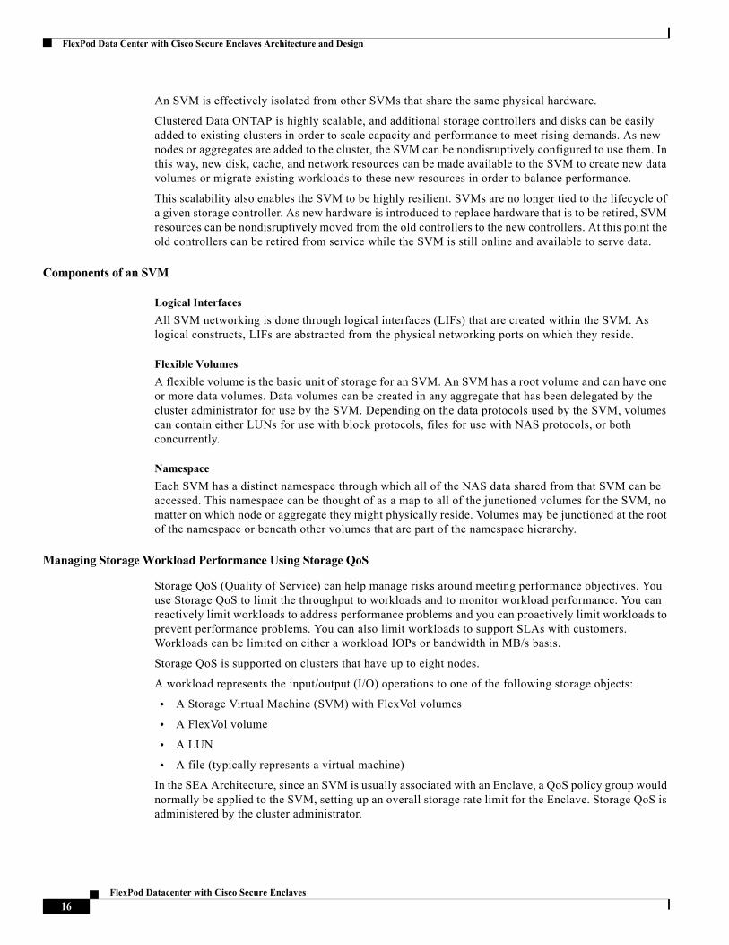
The cDOT SVM is a significant element of the FlexPod Data Center with Cisco Secure Enclaves design. As show in Figure 8, the physical network resources of two NetApp FAS3200 series controllers have been partitioned into three logical controllers namely the Infrastructure SVM, Enclave1 SVM and Enclave2 SVM. Each SVM is allocated to an Enclave supporting one or more applications removing the requirement for dedicated physical storage as the FAS device logically consolidates and separates the storage partitions. The Enclaves SVM have the following characteristics:
• Dedicated Logical Interfaces (LIFs) are created in each SVM from the physical NetApp Unified Target Adapters (UTAs)
• SAN LIF presence supporting SAN A(e3) and SAN B (e4) topologies
– Zoning provides SAN traffic isolation within the fabric
• The NetApp ifgroup aggregates the Ethernet interfaces (e3a, e4a) of the UTA for high availability and supports Layer 2 VLANs
• IP LIFs use the ifgroup construct for NFS(enclave_ds1) and or iSCSI based LIFs
• Management IP LIFs (svm_mgmt) are defined on each SVM for administration of that SVM and its logical resources. The management is contained to the SVM.
• Dedicated VLANs to each LIF assure traffic separation across the Ethernet fabric
Figure 8 NetApp FAS Enclave Storage Design Using cDOT Storage Virtual Machines
In addition, each SVM brings other features to support the granular separation and control of the FlexPod storage domain. These include:
• QoS policies allowing the administrator to manage system performance and resource consumption per Enclave through policies based on IOPS or Mbps throughput.
• Role based access control with predefined roles for at cDOT cluster layer and per individual SVM
17FlexPod Datacenter with Cisco Secure Enclaves
FlexPod Data Center with Cisco Secure Enclaves Architecture and Design
• Performance monitoring
• Management security through firewall policy limiting access to trusted protocols.
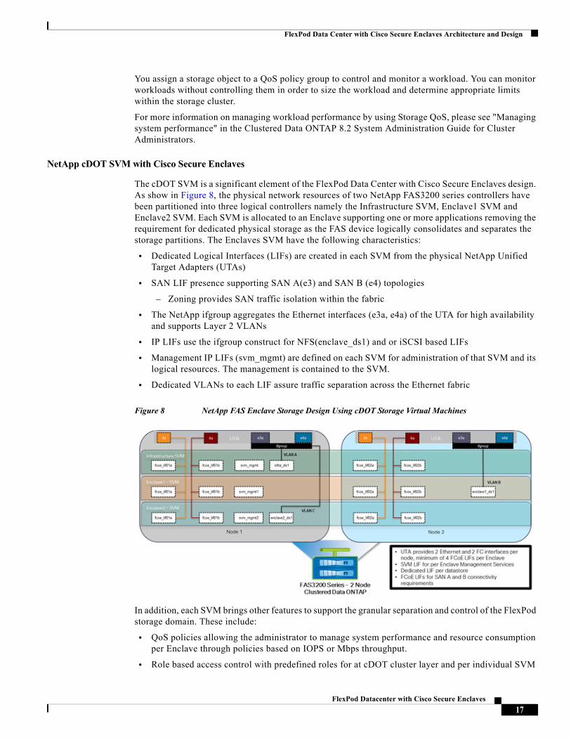
Figure 9 describes another deployment model for the Cisco Secure Enclave on NetApp cDOT. The Enclaves do not receive a dedicated SVM but share a single SVM with multiple LIFs defined to support specific data stores. This model does not provide the same level of granularity, but it may provide a simpler operational model for larger deployments.
Figure 9 NetApp FAS Enclave Storage Design Using cDOT Storage Virtual Machines (Service Provider Model)
Compute Design
The Cisco UCS Manager resides on a pair of Cisco UCS 6200 Series Fabric Interconnects using a clustered, active-standby configuration for high availability. The software gives administrators a single interface for performing server provisioning, device discovery, inventory, configuration, diagnostics, monitoring, fault detection, auditing, and statistics collection. Cisco UCS Manager service profiles and templates support versatile role- and policy-based management, and system configuration information can be exported to configuration management databases (CMDBs) to facilitate processes based on IT Infrastructure Library (ITIL) concepts.
Compute nodes are deployed in a Cisco UCS environment by leveraging Cisco UCS service profiles. Service profiles let server, network, and storage administrators treat Cisco UCS servers as raw computing capacity to be allocated and reallocated as needed. The profiles define server I/O properties, personalities, properties and firmware revisions and are stored in the Cisco UCS 6200 Series Fabric Interconnects. Using service profiles, administrators can provision infrastructure resources in minutes instead of days, creating a more dynamic environment and more efficient use of server capacity.
Each service profile consists of a server software definition and the server's LAN and SAN connectivity requirements. When a service profile is deployed to a server, Cisco UCS Manager automatically configures the server, adapters, fabric extenders, and fabric interconnects to match the configuration specified in the profile. The automatic configuration of servers, network interface cards (NICs), host bus adapters (HBAs), and LAN and SAN switches lowers the risk of human error, improves consistency, and decreases server deployment times.
18FlexPod Datacenter with Cisco Secure Enclaves
FlexPod Data Center with Cisco Secure Enclaves Architecture and Design
Service profiles benefit both virtualized and non-virtualized environments in the Cisco Secure Enclave deployment. The profiles increase the mobility of non-virtualized servers, such as when moving workloads from server to server or taking a server offline for service or upgrade. Profiles can also be used in conjunction with virtualization clusters to bring new resources online easily, complementing existing virtual machine mobility. The profiles are a standard, a template that can be readily deployed and secured.
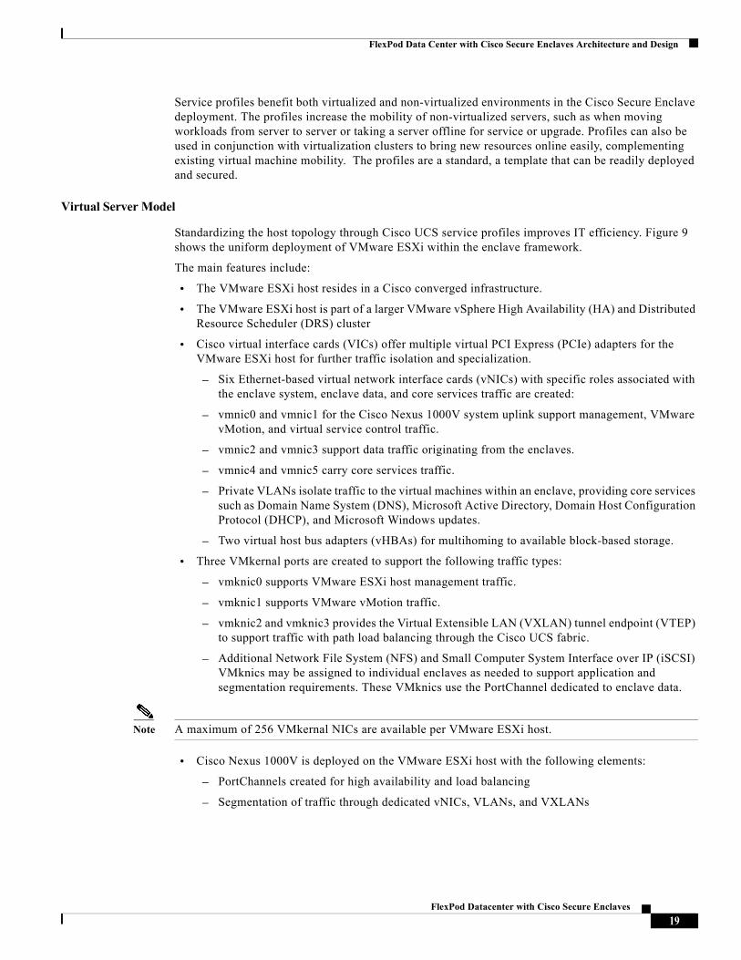
Virtual Server Model
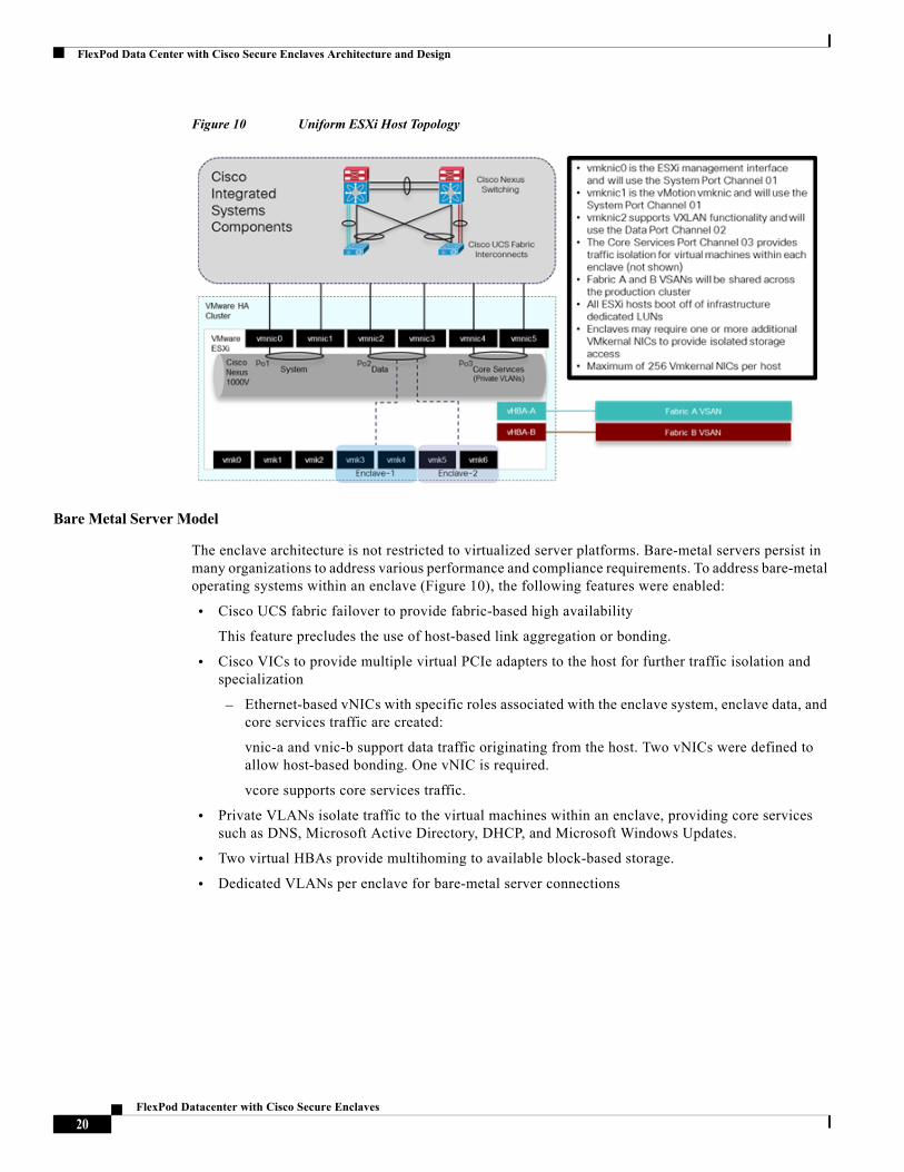
Standardizing the host topology through Cisco UCS service profiles improves IT efficiency. Figure 9 shows the uniform deployment of VMware ESXi within the enclave framework.
The main features include:
• The VMware ESXi host resides in a Cisco converged infrastructure.
• The VMware ESXi host is part of a larger VMware vSphere High Availability (HA) and Distributed Resource Scheduler (DRS) cluster
• Cisco virtual interface cards (VICs) offer multiple virtual PCI Express (PCIe) adapters for the VMware ESXi host for further traffic isolation and specialization.
– Six Ethernet-based virtual network interface cards (vNICs) with specific roles associated with the enclave system, enclave data, and core services traffic are created:
– vmnic0 and vmnic1 for the Cisco Nexus 1000V system uplink support management, VMware vMotion, and virtual service control traffic.
– vmnic2 and vmnic3 support data traffic originating from the enclaves.
– vmnic4 and vmnic5 carry core services traffic.
– Private VLANs isolate traffic to the virtual machines within an enclave, providing core services such as Domain Name System (DNS), Microsoft Active Directory, Domain Host Configuration Protocol (DHCP), and Microsoft Windows updates.
– Two virtual host bus adapters (vHBAs) for multihoming to available block-based storage.
• Three VMkernal ports are created to support the following traffic types:
– vmknic0 supports VMware ESXi host management traffic.
– vmknic1 supports VMware vMotion traffic.
– vmknic2 and vmknic3 provides the Virtual Extensible LAN (VXLAN) tunnel endpoint (VTEP) to support traffic with path load balancing through the Cisco UCS fabric.
– Additional Network File System (NFS) and Small Computer System Interface over IP (iSCSI) VMknics may be assigned to individual enclaves as needed to support application and segmentation requirements. These VMknics use the PortChannel dedicated to enclave data.
Note A maximum of 256 VMkernal NICs are available per VMware ESXi host.
• Cisco Nexus 1000V is deployed on the VMware ESXi host with the following elements:
– PortChannels created for high availability and load balancing
– Segmentation of traffic through dedicated vNICs, VLANs, and VXLANs
19FlexPod Datacenter with Cisco Secure Enclaves
FlexPod Data Center with Cisco Secure Enclaves Architecture and Design
Figure 10 Uniform ESXi Host Topology
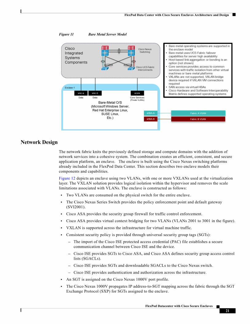
Bare Metal Server Model
The enclave architecture is not restricted to virtualized server platforms. Bare-metal servers persist in many organizations to address various performance and compliance requirements. To address bare-metal operating systems within an enclave (Figure 10), the following features were enabled:
• Cisco UCS fabric failover to provide fabric-based high availability
This feature precludes the use of host-based link aggregation or bonding.
• Cisco VICs to provide multiple virtual PCIe adapters to the host for further traffic isolation and specialization
– Ethernet-based vNICs with specific roles associated with the enclave system, enclave data, and core services traffic are created:
vnic-a and vnic-b support data traffic originating from the host. Two vNICs were defined to allow host-based bonding. One vNIC is required.
vcore supports core services traffic.
• Private VLANs isolate traffic to the virtual machines within an enclave, providing core services such as DNS, Microsoft Active Directory, DHCP, and Microsoft Windows Updates.
• Two virtual HBAs provide multihoming to available block-based storage.
• Dedicated VLANs per enclave for bare-metal server connections
20FlexPod Datacenter with Cisco Secure Enclaves
FlexPod Data Center with Cisco Secure Enclaves Architecture and Design
Figure 11 Bare Metal Server Model
Network Design
The network fabric knits the previously defined storage and compute domains with the addition of network services into a cohesive system. The combination creates an efficient, consistent, and secure application platform, an enclave. The enclave is built using the Cisco Nexus switching platforms already included in the FlexPod Data Center. This section describes two enclave models their components and capabilities.
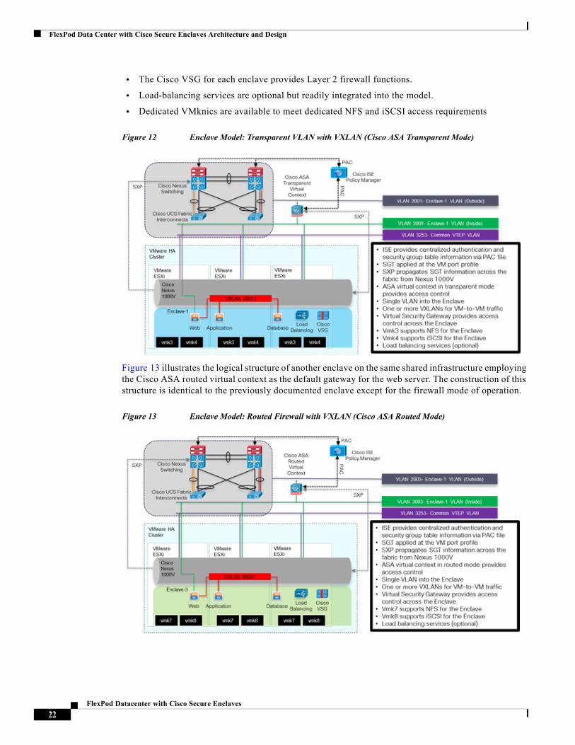
Figure 12 depicts an enclave using two VLANs, with one or more VXLANs used at the virtualization layer. The VXLAN solution provides logical isolation within the hypervisor and removes the scale limitations associated with VLANs. The enclave is constructed as follows:
• Two VLANs are consumed on the physical switch for the entire enclave.
• The Cisco Nexus Series Switch provides the policy enforcement point and default gateway (SVI2001).
• Cisco ASA provides the security group firewall for traffic control enforcement.
• Cisco ASA provides virtual context bridging for two VLANs (VLANs 2001 to 3001 in the figure).
• VXLAN is supported across the infrastructure for virtual machine traffic.
• Consistent security policy is provided through universal security group tags (SGTs):
– The import of the Cisco ISE protected access credential (PAC) file establishes a secure communication channel between Cisco ISE and the device.
– Cisco ISE provides SGTs to Cisco ASA, and Cisco ASA defines security group access control lists (SGACLs).
– Cisco ISE provides SGTs and downloadable SGACLs to the Cisco Nexus switch.
– Cisco ISE provides authentication and authorization across the infrastructure.
• An SGT is assigned on the Cisco Nexus 1000V port profile.
• The Cisco Nexus 1000V propagates IP address-to-SGT mapping across the fabric through the SGT Exchange Protocol (SXP) for SGTs assigned to the enclave.
21FlexPod Datacenter with Cisco Secure Enclaves
FlexPod Data Center with Cisco Secure Enclaves Architecture and Design
• The Cisco VSG for each enclave provides Layer 2 firewall functions.
• Load-balancing services are optional but readily integrated into the model.
• Dedicated VMknics are available to meet dedicated NFS and iSCSI access requirements
Figure 12 Enclave Model: Transparent VLAN with VXLAN (Cisco ASA Transparent Mode)
Figure 13 illustrates the logical structure of another enclave on the same shared infrastructure employing the Cisco ASA routed virtual context as the default gateway for the web server. The construction of this structure is identical to the previously documented enclave except for the firewall mode of operation.
Figure 13 Enclave Model: Routed Firewall with VXLAN (Cisco ASA Routed Mode)
22FlexPod Datacenter with Cisco Secure Enclaves
FlexPod Data Center with Cisco Secure Enclaves Architecture and Design
Security Services
Firewall
Firewalls are the primary control point for access between two distinct network segments, commonly referred to as inside, outside, public or private. The Cisco Secure Enclave Architecture uses two categories of firewalls zone or edge for access control into, between and within the enclave. The enclave model promotes security "proximity", meaning where possible traffic patterns within an enclave should remain contiguous to the compute. The use of multiple policy enforcement points promotes optimized paths.
Cisco Virtual Security Gateway
The Cisco Virtual Security Gateway (VSG) protects traffic within the enclave, enforcing security policy at the VM level by applying policy based on VM or network based attributes. Typically this traffic is considered "east, west" in nature. The reality is any traffic into a VM is subject to the VSG security policy. The enclave model calls for a single VSG instance per enclave allowing the security operations team to develop granular security rules based on the application and associated business requirements.
The Cisco Nexus 1000v Virtual Ethernet Module (VEM) will redirect the initial packet destined to a VM to the VSG where policy evaluation occurs. The redirection of traffic occurs using vPath when the virtual service is defined on the port profile of the VM. The VEM encapsulates the packet and forwards it to the VSG assigned to the enclave. The Cisco VSG processes the packet and forwards the result to the vPath on the VEM where the policy decision is cached and enforced for subsequent packets. The vPath will maintain the cache until the flow is reset (RST), finished (FIN) or timeouts.
Note The Cisco Virtual Security Gateway may deployed adjacent to the Cisco Nexus 1000v VEM or across a number of Layer 3 hops.
Cisco Adaptive Security Appliances
The edge of the enclave is protected using the Cisco's Adaptive Security Appliance. The Cisco ASA can be partitioned into multiple security context (<250) allowing each enclave to have a dedicated virtual ASA to apply access control, intrusion prevention, and antivirus policy. The primary role of each ASA enclave context is to control access between the "inside and outside" network segments. This traffic is typically referred to as "north, south" in nature.
The Cisco ASA supports Cisco TrustSec. Cisco TrustSec is an intelligent solution providing secure network access based on the context of a user or a device. Subsequently network access is granted based on contextual data such as "who, what, where, when, and how,". Cisco TrustSec in the enclave architecture uses Security Group Tag (SGT) assignment on the Cisco Nexus 1000v and the ASA as a Security Group Firewall (SGFW) to enforce the role based access control policy.
The Cisco Identity Services Engine (ISE) is a required component in the CiscoTrustSec implementation providing centralized definitions of the SGTs to IP mapping. A Protected Access Credential (PAC) file secures the communication between the ISE and ASA platforms and allows for the ASA to download the security group table. This table contains SGT to security group names translation. The security operations team can then create access rules based on the object tags (SGTs), simplifying policy configuration in the data center.
The SGT is assigned at the VM port profile on the Cisco Nexus 1000v. The SGT assignment is propagated to the ASA through the Security eXchange Protocol (SXP). SXP is a secure conversation between the two devices a speaker and listener. The ASA may perform both roles but in this design it is strictly a listener learning and acting as a SGFW. If the IP to SGT mapping is part of a security group policy the ASA enforces the rule.
23FlexPod Datacenter with Cisco Secure Enclaves
FlexPod Data Center with Cisco Secure Enclaves Architecture and Design
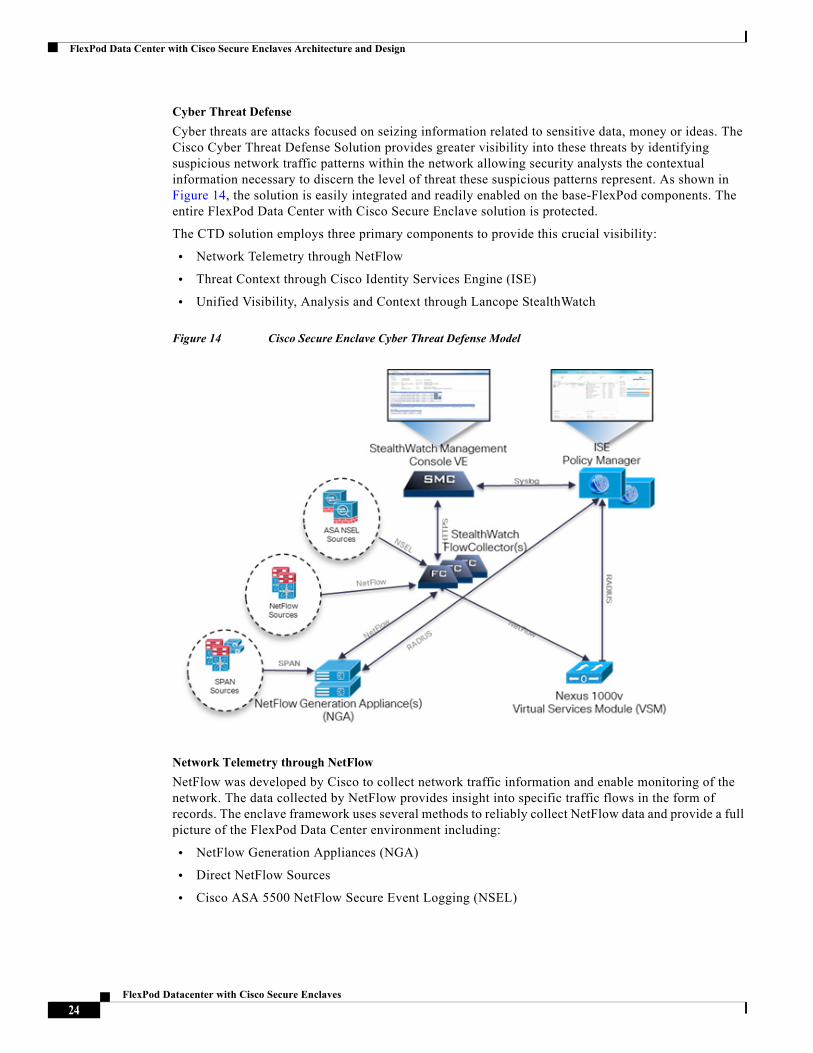
Cyber Threat Defense
Cyber threats are attacks focused on seizing information related to sensitive data, money or ideas. The Cisco Cyber Threat Defense Solution provides greater visibility into these threats by identifying suspicious network traffic patterns within the network allowing security analysts the contextual information necessary to discern the level of threat these suspicious patterns represent. As shown in Figure 14, the solution is easily integrated and readily enabled on the base-FlexPod components. The entire FlexPod Data Center with Cisco Secure Enclave solution is protected.
The CTD solution employs three primary components to provide this crucial visibility:
• Network Telemetry through NetFlow
• Threat Context through Cisco Identity Services Engine (ISE)
• Unified Visibility, Analysis and Context through Lancope StealthWatch
Figure 14 Cisco Secure Enclave Cyber Threat Defense Model
Network Telemetry through NetFlow
NetFlow was developed by Cisco to collect network traffic information and enable monitoring of the network. The data collected by NetFlow provides insight into specific traffic flows in the form of records. The enclave framework uses several methods to reliably collect NetFlow data and provide a full picture of the FlexPod Data Center environment including:
• NetFlow Generation Appliances (NGA)
• Direct NetFlow Sources
• Cisco ASA 5500 NetFlow Secure Event Logging (NSEL)
24FlexPod Datacenter with Cisco Secure Enclaves
FlexPod Data Center with Cisco Secure Enclaves Architecture and Design
The effectiveness of any monitoring system is dependent on the completeness of the data it captures.With that in mind, the enclave model does not recommend using sampled NetFlow. Ideally the NetFlow records should reflect the FlexPod traffic in its entirety. To that end the physical Cisco Nexus switches are relieved of NetFlow responsibilities and implement line-rate SPAN. The NGA are connected to SPAN destination ports on the Cisco Nexus switches and Cisco UCS Fabric Interconnects. The collection points are described in the NetFlow Generation Appliance (NGA) Extension section. The NGA devices are promiscuous supporting up to 40Gbps of mirrored traffic to create NetFlow records for export to the Lancope StealthWatch Flow Collectors.
Direct NetFlow sources generate and send flow records directly to the Lancope FlowCollectors. The Cisco Nexus 1000v virtual distributed switch provides this functionality for the virtual access layer of the enclave. It is recommended to enable Netflow on the Cisco Nexus 1000v interfaces. In larger environments where the limits of the Cisco Nexus 1000v NetFlow resources are reached, NetFlow should be enabled on VM interfaces with data sources.
Another source of direct flow data is the Cisco ASA 5500. The Cisco ASA generates a NSEL records. These records differ from traditional NetFlow but are fully supported by the Lancope StealthWatch system. In fact, the records include the "action" permit or deny taken by the ASA on the flow as well as NAT translation that adds another layer of depth to the telemetry of the CTD system.
Threat Context through Cisco Identity Services Engine (ISE)
In order to provide some context or perspective, the Lancope StealthWatch system employs the services of the Cisco Identity Services Engine. The ISE can provide device and user information, offering more information for the security operations team to use during the process of threat analysis and potential response. In addition to the device profile and user identity, the ISE can provide time, location, and network data to create a contextual identity to who and what is on the network.
Unified Visibility, Analysis and Context through Lancope StealthWatch
The Lancope StealthWatch system collects, organizes and analyzes all of the incoming data points to provide a cohesive view into the inner workings of the enclave. The StealthWatch Management Console (SMC) is the central point of control supporting millions of flows. The primary SMC dashboards offer insight into network reconnaissance, malware propagation, command and control traffic, data exfiltration, and internal host reputation. The combination of Cisco and Lancope technologies offers a protection
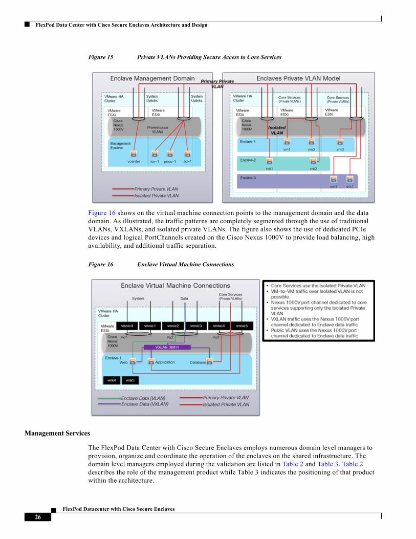
Management Design
The communication between the management domain, the hardware infrastructure, and the enclaves is established through traditional paths as well as through the use of private VLANs on the Cisco Nexus 1000V and Cisco UCS fabric interconnects. The use of dedicated out-of-band management VLANs for the hardware infrastructure, including Cisco Nexus switching and the Cisco UCS fabric, is a recommended practice. The enclave model suggests the use of a single isolated private VLAN that is maintained between the bare-metal and virtual environments. This private isolated VLAN allows all virtual machines and bare-metal servers to converse with the services in the management domain, which is a promiscuous region. The private VLAN feature enforces separation between servers within a single enclave and between enclaves.
Figure 15 shows the logical construction of this private VLAN environment, which supports directory, DNS, Microsoft Windows Server Update Services (WSUS), and other common required services for an organization
25FlexPod Datacenter with Cisco Secure Enclaves
FlexPod Data Center with Cisco Secure Enclaves Architecture and Design
Figure 15 Private VLANs Providing Secure Access to Core Services
Figure 16 shows on the virtual machine connection points to the management domain and the data domain. As illustrated, the traffic patterns are completely segmented through the use of traditional VLANs, VXLANs, and isolated private VLANs. The figure also shows the use of dedicated PCIe devices and logical PortChannels created on the Cisco Nexus 1000V to provide load balancing, high availability, and additional traffic separation.
Figure 16 Enclave Virtual Machine Connections
Management Services
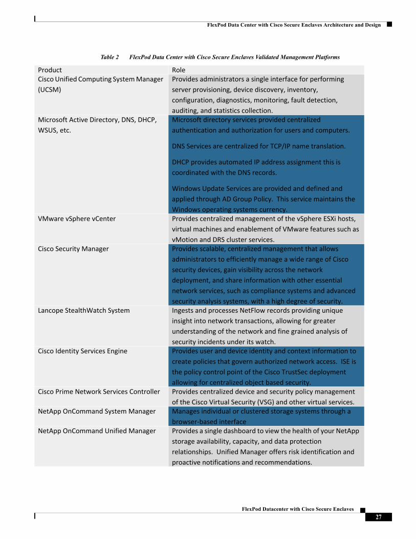
The FlexPod Data Center with Cisco Secure Enclaves employs numerous domain level managers to provision, organize and coordinate the operation of the enclaves on the shared infrastructure. The domain level managers employed during the validation are listed in Table 2 and Table 3. Table 2 describes the role of the management product while Table 3 indicates the positioning of that product within the architecture.
26FlexPod Datacenter with Cisco Secure Enclaves
FlexPod Data Center with Cisco Secure Enclaves Architecture and Design
Table 2 FlexPod Data Center with Cisco Secure Enclaves Validated Management Platforms
Product RoleCisco Unified Computing System Manager (UCSM)
Provides administrators a single interface for performing server provisioning, device discovery, inventory, configuration, diagnostics, monitoring, fault detection, auditing, and statistics collection.
Microsoft Active Directory, DNS, DHCP, WSUS, etc.
Microsoft directory services provided centralized authentication and authorization for users and computers.
DNS Services are centralized for TCP/IP name translation.
DHCP provides automated IP address assignment this is coordinated with the DNS records.
Windows Update Services are provided and defined and applied through AD Group Policy. This service maintains the Windows operating systems currency.
VMware vSphere vCenter Provides centralized management of the vSphere ESXi hosts, virtual machines and enablement of VMware features such as vMotion and DRS cluster services.
Cisco Security Manager Provides scalable, centralized management that allows administrators to efficiently manage a wide range of Cisco security devices, gain visibility across the network deployment, and share information with other essential network services, such as compliance systems and advanced security analysis systems, with a high degree of security.
Lancope StealthWatch System Ingests and processes NetFlow records providing unique insight into network transactions, allowing for greater understanding of the network and fine grained analysis of security incidents under its watch.
Cisco Identity Services Engine Provides user and device identity and context information to create policies that govern authorized network access. ISE is the policy control point of the Cisco TrustSec deployment allowing for centralized object based security.
Cisco Prime Network Services Controller Provides centralized device and security policy management of the Cisco Virtual Security (VSG) and other virtual services.
NetApp OnCommand System Manager Manages individual or clustered storage systems through a browser-based interface
NetApp OnCommand Unified Manager Provides a single dashboard to view the health of your NetApp storage availability, capacity, and data protection relationships. Unified Manager offers risk identification and proactive notifications and recommendations.
27FlexPod Datacenter with Cisco Secure Enclaves
FlexPod Data Center with Cisco Secure Enclaves Architecture and Design
Table 3 FlexPod Data Center with Cisco Secure Enclaves Validated Management Platforms
Unified Management with Cisco UCS Director
Cisco UCS Director provides a central user portal for managing the environment and enables the automation of the manual tasks associated with the provisioning and subsequent operation of the enclave. Cisco UCS Director can directly or indirectly manage the individual FlexPod Data Center components and enclave extensions.
NetApp Virtual Storage Console (VSC) Provides integrated, comprehensive, end-to-end virtual storage management for the VMware vSphere infrastructure, including discovery, health monitoring, capacity management, provisioning, cloning, backup, restore, and disaster recovery.
NetApp NFS Plug-in for VMware vStorage APIs for Array Integration (VAAI)
VAAI is a set of APIs and SCSI commands allowing VMware ESXi hosts to offload VM operations such as cloning and initialization to the FAS controllers.
NetApp OnCommand Balance Provides directions to optimize the performance and capacity of the virtual and physical data center resources including NetApp storage, physical servers, and VMware virtual machines.
Cisco Nexus 1000v Virtual Supervisor Module for VMware vSphere
Provides a comprehensive and extensible architectural platform for virtual machine (VM) and cloud networking
Cisco Virtual Security Gateway Delivers security, compliance, and trusted access for virtual data center and cloud computing environments
Cisco Prime Network Analysis Module (NAM)
Delivers application visibility and network analytics to the physical and virtual network
Product PositionedMicrosoft Active Directory, DNS, DHCP, WSUS, etc.
VMware vSphere Management Cluster
VMware vSphere vCenter VMware vSphere Management ClusterCisco Security Manager VMware vSphere Management ClusterLancope StealthWatch System VMware vSphere Management ClusterCisco Identity Services Engine VMware vSphere Management ClusterCisco Prime Network Services Controller VMware vSphere Management ClusterNetApp OnCommand System Manager VMware vSphere Management ClusterNetApp OnCommand Unified Manager VMware vSphere Management ClusterNetApp Virtual Storage Console (VSC) VMware vSphere Management ClusterNetApp NFS Plug-in for VMware vStorage APIs for Array Integration (VAAI)
VMware ESXi Host
NetApp OnCommand Balance VMware vSphere Management ClusterCisco Nexus 1000v Virtual Supervisor Module
Nexus 1110-X Platform
Cisco Virtual Security Gateway Nexus 1110-X PlatformCisco Prime Network Analysis Module (NAM)
Nexus 1110-X Platform
28FlexPod Datacenter with Cisco Secure Enclaves
FlexPod Data Center with Cisco Secure Enclaves Architecture and Design
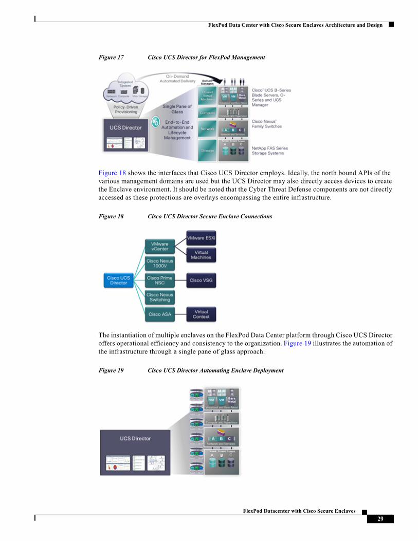
Figure 17 Cisco UCS Director for FlexPod Management
Figure 18 shows the interfaces that Cisco UCS Director employs. Ideally, the north bound APIs of the various management domains are used but the UCS Director may also directly access devices to create the Enclave environment. It should be noted that the Cyber Threat Defense components are not directly accessed as these protections are overlays encompassing the entire infrastructure.
Figure 18 Cisco UCS Director Secure Enclave Connections
The instantiation of multiple enclaves on the FlexPod Data Center platform through Cisco UCS Director offers operational efficiency and consistency to the organization. Figure 19 illustrates the automation of the infrastructure through a single pane of glass approach.
Figure 19 Cisco UCS Director Automating Enclave Deployment
29FlexPod Datacenter with Cisco Secure Enclaves
Enclave Implementation
Enclave ImplementationThe implementation section of this document builds off of the baseline FlexPod Data Center deployment guides and assumes this baseline infrastructure is in place containing Cisco UCS, NetApp FAS and Cisco Nexus configuration. Please reference the following documents for FlexPod Data Center deployment with the Cisco Nexus 7000 or Cisco Nexus 5000 series switches.
VMware vSphere 5.1 on FlexPod Deployment Guide for Clustered ONTAP at http://www.cisco.com/en/US/docs/unified_computing/ucs/UCS_CVDs/esxi51_ucsm2_Clusterdeploy.html
VMware vSphere 5.1 on FlexPod with the Cisco Nexus 7000 Deployment Guide at http://www.cisco.com/en/US/docs/unified_computing/ucs/UCS_CVDs/flexpod_esxi_N7k.html
The deployment details provide example configurations necessary to achieve enclave functionality. It is assumed that the reader has installed and has some familiarity with the products.
Cisco Nexus Switching
The FlexPod Data Center solution supports multiple Cisco Nexus family switches including the Cisco Nexus 9000, Cisco Nexus 7000, Cisco Nexus 6000, and Cisco Nexus 5000 series switches. This section of the document will address using either the Cisco Nexus 7000 or Cisco Nexus 5000 series switches as the FlexPod Data Center networking platform.
Cisco Nexus 7000 as FlexPod Data Center Switch
The Cisco Nexus 7000 has three Virtual Device Contexts (VDC); one admin VDC, one storage VDC and one LAN or Ethernet VDC. VDC are abstractions of the physical switch and offer operational benefits of fault isolation and traffic isolation. The VDCs were built using the deployment guidance of the FlexPod Data Center with Cisco Nexus 7000 document. The majority of the configurations are identical to the based FlexPod implementation. This section discusses the modifications.
ISE Integration
Two Identity Services Engines are provisioned in a primary secondary configuration for high availability. Each ISE assumes the following personas:
• Administration Node
• Policy Service Node
• Monitoring Node
The ISE provides RADIUS services to each of the Cisco Nexus 7000 VDCs which are configured as Network.
30FlexPod Datacenter with Cisco Secure Enclaves
Enclave Implementation
The following AAA commands were used:
Cisco TrustSec
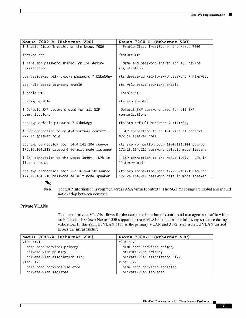
Cisco TrustSec provides an access-control solution that builds upon an existing identity-aware infrastructure to ensure data confidentiality between network devices and integrate security access services on one platform. In the Cisco TrustSec solution, enforcement devices utilize a combination of user attributes and end-point attributes to make role-based and identity-based access control decisions.
Nexus 7000-A (Ethernet VDC) Nexus 7000-B (Ethernet VDC) radius-server key 7 "K1kmN0gy"
radius distribute
radius-server host 172.26.164.187 key 7 "K1kmN0gy" authentication accounting
radius-server host 172.26.164.239 key 7 "K1kmN0gy" authentication accounting
radius commit
aaa group server radius ISE-Radius-Grp
server 172.26.164.187
server 172.26.164.239
use-vrf management
source-interface mgmt0
ip radius source-interface mgmt0
radius-server key 7 "K1kmN0gy"
radius distribute
radius-server host 172.26.164.187 key 7 "K1kmN0gy" authentication accounting
radius-server host 172.26.164.239 key 7 "K1kmN0gy" authentication accounting
radius commit
aaa group server radius ISE-Radius-Grp
server 172.26.164.187
server 172.26.164.239
use-vrf management
source-interface mgmt0
ip radius source-interface mgmt0
Nexus 7000-A (Ethernet VDC) Nexus 7000-B (Ethernet VDC) aaa authentication login default group ISE-Radius-Grp
aaa authentication dot1x default group ISE-Radius-Grp
aaa accounting dot1x default group ISE-Radius-Grp
aaa authorization cts default group ISE-Radius-Grp
aaa accounting default group ISE-Radius-Grp
no aaa user default-role
aaa authentication login default group ISE-Radius-Grp
aaa authentication dot1x default group ISE-Radius-Grp
aaa accounting dot1x default group ISE-Radius-Grp
aaa authorization cts default group ISE-Radius-Grp
aaa accounting default group ISE-Radius-Grp
no aaa user default-role
31FlexPod Datacenter with Cisco Secure Enclaves
Enclave Implementation
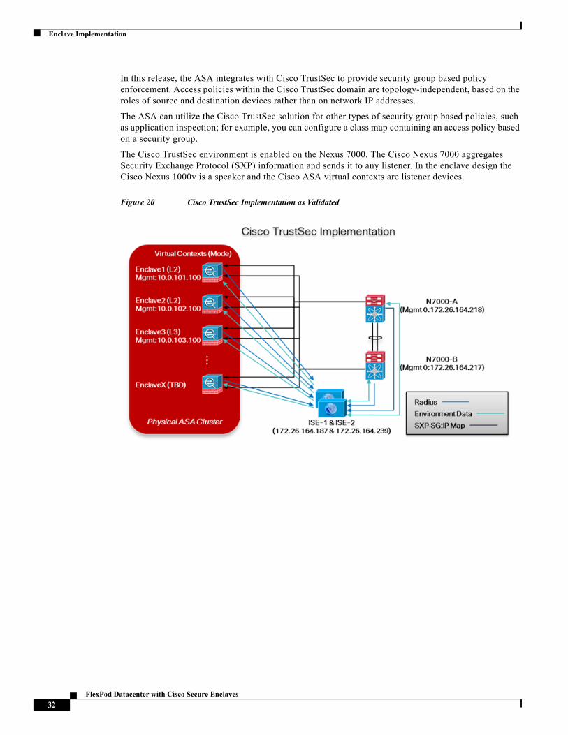
In this release, the ASA integrates with Cisco TrustSec to provide security group based policy enforcement. Access policies within the Cisco TrustSec domain are topology-independent, based on the roles of source and destination devices rather than on network IP addresses.
The ASA can utilize the Cisco TrustSec solution for other types of security group based policies, such as application inspection; for example, you can configure a class map containing an access policy based on a security group.
The Cisco TrustSec environment is enabled on the Nexus 7000. The Cisco Nexus 7000 aggregates Security Exchange Protocol (SXP) information and sends it to any listener. In the enclave design the Cisco Nexus 1000v is a speaker and the Cisco ASA virtual contexts are listener devices.
Figure 20 Cisco TrustSec Implementation as Validated
32FlexPod Datacenter with Cisco Secure Enclaves
Enclave Implementation
Note The SXP information is common across ASA virtual contexts The SGT mappings are global and should not overlap between contexts.
Private VLANs
The use of private VLANs allows for the complete isolation of control and management traffic within an Enclave. The Cisco Nexus 7000 supports private VLANs and used the following structure during validation. In this sample, VLAN 3171 is the primary VLAN and 3172 is an isolated VLAN carried across the infrastructure.
Nexus 7000-A (Ethernet VDC) Nexus 7000-B (Ethernet VDC) ! Enable Cisco TrustSec on the Nexus 7000
feature cts
! Name and password shared for ISE device registration
cts device-id k02-fp-sw-a password 7 K1kmN0gy
cts role-based counters enable
!Enable SXP
cts sxp enable
! Default SXP password used for all SXP communications
cts sxp default password 7 K1kmN0gy
! SXP connection to an ASA virtual context – N7k in speaker role
cts sxp connection peer 10.0.101.100 source 172.26.164.218 password default mode listener
! SXP connection to the Nexus 1000v – N7k in listener mode
cts sxp connection peer 172.26.164.18 source 172.26.164.218 password default mode speaker
! Enable Cisco TrustSec on the Nexus 7000
feature cts
! Name and password shared for ISE device registration
cts device-id k02-fp-sw-b password 7 K1kmN0gy
cts role-based counters enable
!Enable SXP
cts sxp enable
!Default SXP password used for all SXP communications
cts sxp default password 7 K1kmN0gy
! SXP connection to an ASA virtual context – N7k in speaker role
cts sxp connection peer 10.0.101.100 source 172.26.164.217 password default mode listener
! SXP connection to the Nexus 1000v – N7k in listener mode
cts sxp connection peer 172.26.164.18 source 172.26.164.217 password default mode speaker
Nexus 7000-A (Ethernet VDC) Nexus 7000-B (Ethernet VDC) vlan 3171 name core-services-primary private-vlan primary private-vlan association 3172vlan 3172 name core-services-isolated private-vlan isolated
vlan 3171 name core-services-primary private-vlan primary private-vlan association 3172vlan 3172 name core-services-isolated private-vlan isolated
33FlexPod Datacenter with Cisco Secure Enclaves
Enclave Implementation
Port Profiles
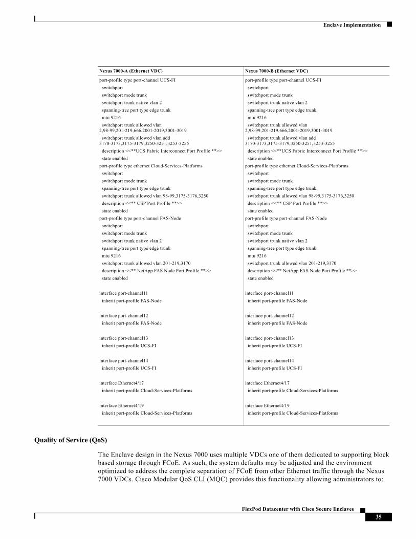
A port profile is a mechanism for simplifying the configuration of interfaces. A single port profile can be assigned to multiple interfaces to give them all the same configuration. Changes to a port profile are propagated to the configuration of any interface that is assigned to it.
In the validated architecture, three port profiles were created supporting the Cisco UCS, NetApp FAS controllers and Cisco Nexus 1110 Cloud Services Platform. The following details the port profile configurations which are applied to the virtual and physical interfaces on the Cisco Nexus 7000.
34FlexPod Datacenter with Cisco Secure Enclaves
Enclave Implementation
Quality of Service (QoS)
The Enclave design in the Nexus 7000 uses multiple VDCs one of them dedicated to supporting block based storage through FCoE. As such, the system defaults may be adjusted and the environment optimized to address the complete separation of FCoE from other Ethernet traffic through the Nexus 7000 VDCs. Cisco Modular QoS CLI (MQC) provides this functionality allowing administrators to:
Nexus 7000-A (Ethernet VDC) Nexus 7000-B (Ethernet VDC)
port-profile type port-channel UCS-FI
switchport
switchport mode trunk
switchport trunk native vlan 2
spanning-tree port type edge trunk
mtu 9216
switchport trunk allowed vlan 2,98-99,201-219,666,2001-2019,3001-3019
switchport trunk allowed vlan add 3170-3173,3175-3179,3250-3251,3253-3255
description <<**UCS Fabric Interconnect Port Profile **>>
state enabled
port-profile type ethernet Cloud-Services-Platforms
switchport
switchport mode trunk
spanning-tree port type edge trunk
switchport trunk allowed vlan 98-99,3175-3176,3250
description <<** CSP Port Profile **>>
state enabled
port-profile type port-channel FAS-Node
switchport
switchport mode trunk
switchport trunk native vlan 2
spanning-tree port type edge trunk
mtu 9216
switchport trunk allowed vlan 201-219,3170
description <<** NetApp FAS Node Port Profile **>>
state enabled
interface port-channel11
inherit port-profile FAS-Node
interface port-channel12
inherit port-profile FAS-Node
interface port-channel13
inherit port-profile UCS-FI
interface port-channel14
inherit port-profile UCS-FI
interface Ethernet4/17
inherit port-profile Cloud-Services-Platforms
interface Ethernet4/19
inherit port-profile Cloud-Services-Platforms
35FlexPod Datacenter with Cisco Secure Enclaves
Enclave Implementation
• Create traffic classes by classifying the incoming and outgoing packets that match criteria such as IP address or QoS fields.
• Create policies by specifying actions to take on the traffic classes, such as limiting, marking, or dropping packets.
• Apply policies to a port, port channel, VLAN, or a sub-interface.
Queues (optional modifications)
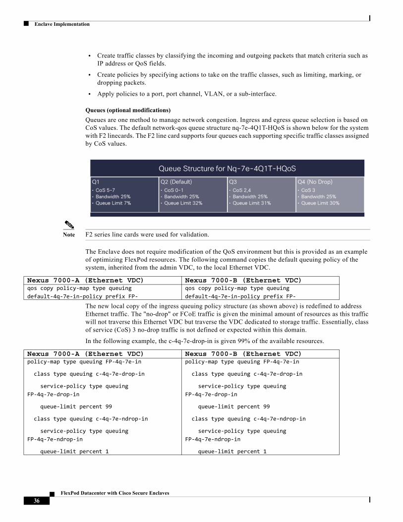
Queues are one method to manage network congestion. Ingress and egress queue selection is based on CoS values. The default network-qos queue structure nq-7e-4Q1T-HQoS is shown below for the system with F2 linecards. The F2 line card supports four queues each supporting specific traffic classes assigned by CoS values.
Note F2 series line cards were used for validation.
The Enclave does not require modification of the QoS environment but this is provided as an example of optimizing FlexPod resources. The following command copies the default queuing policy of the system, inherited from the admin VDC, to the local Ethernet VDC.
The new local copy of the ingress queuing policy structure (as shown above) is redefined to address Ethernet traffic. The "no-drop" or FCoE traffic is given the minimal amount of resources as this traffic will not traverse this Ethernet VDC but traverse the VDC dedicated to storage traffic. Essentially, class of service (CoS) 3 no-drop traffic is not defined or expected within this domain.
In the following example, the c-4q-7e-drop-in is given 99% of the available resources.
Nexus 7000-A (Ethernet VDC) Nexus 7000-B (Ethernet VDC) qos copy policy-map type queuing default-4q-7e-in-policy prefix FP-
qos copy policy-map type queuing default-4q-7e-in-policy prefix FP-
Nexus 7000-A (Ethernet VDC) Nexus 7000-B (Ethernet VDC) policy-map type queuing FP-4q-7e-in
class type queuing c-4q-7e-drop-in
service-policy type queuing FP-4q-7e-drop-in
queue-limit percent 99
class type queuing c-4q-7e-ndrop-in
service-policy type queuing FP-4q-7e-ndrop-in
queue-limit percent 1
policy-map type queuing FP-4q-7e-in
class type queuing c-4q-7e-drop-in
service-policy type queuing FP-4q-7e-drop-in
queue-limit percent 99
class type queuing c-4q-7e-ndrop-in
service-policy type queuing FP-4q-7e-ndrop-in
queue-limit percent 1
36FlexPod Datacenter with Cisco Secure Enclaves
Enclave Implementation
The queuing policy maps are then adjusted to reflect the new percentages total. For example, the 4q4t-7e-in-q1 class will receive 50% of the 100% queue-limits within the FP-4q-7e-drop-in class, but that is really 50% of the 99% queue limit available in total meaning the 4q4t-7e-in-q1 will receive 49.5% of the total available queue.
Note Effective queue limit % = assigned queue-limit % from parent class * local queue limit %
The 4q4t-7e-in-q4 under the FP-4q-7e-ndrop-in class will receive 100% of the 1% effectively assigned to it. Again the lab implementation did not expect any CoS traffic in the Ethernet VDC.
37FlexPod Datacenter with Cisco Secure Enclaves
Enclave Implementation
The bandwidth percentage should total 100% across the class queues. The no-drop queue was given the least amount of resources, 1%. Note zero resources is not an option for any queue.
Table 4 Effective Queuing Configuration Example
The queuing policy can be applied to one or more interfaces. To simplify the deployment, the service policy is applied to the relevant port profiles, namely the FAS and Cisco UCS ports.
Note The egress queue buffer allocations are non-configurable for the F2 line cards used for validation.
Nexus 7000-A (Ethernet VDC) Nexus 7000-B (Ethernet VDC) policy-map type queuing FP-4q-7e-drop-in
class type queuing 4q4t-7e-in-q1
queue-limit percent 50
bandwidth percent 50
class type queuing 4q4t-7e-in-q-default
queue-limit percent 25
bandwidth percent 24
class type queuing 4q4t-7e-in-q3
queue-limit percent 25
bandwidth percent 25
policy-map type queuing FP-4q-7e-ndrop-in
class type queuing 4q4t-7e-in-q4
queue-limit percent 100
bandwidth percent 1
policy-map type queuing FP-4q-7e-drop-in
class type queuing 4q4t-7e-in-q1
queue-limit percent 50
bandwidth percent 50
class type queuing 4q4t-7e-in-q-default
queue-limit percent 25
bandwidth percent 24
class type queuing 4q4t-7e-in-q3
queue-limit percent 25
bandwidth percent 25
policy-map type queuing FP-4q-7e-ndrop-in
class type queuing 4q4t-7e-in-q4
queue-limit percent 100
bandwidth percent 1
Queuing ClassQueue-limit % -
Effective %
Bandwidth % -
Effective4q4t-7e-in-q1 (CoS 5-7) 50 – 49.5 50 - 504q4t-7e-in-q-default (CoS 0-1) 25 – 24.75 24 – 244q4t-7e-in-q3 (CoS 2,4) 25 – 24.75 25 – 254q4t-7e-in-q4 (no drop) (CoS 3)
100 – 11 - 1
Nexus 7000-A (Ethernet VDC) Nexus 7000-B (Ethernet VDC) port-profile type port-channel UCS-FI
service-policy type queuing input FP-4q-7e-in
port-profile type port-channel FAS-Node
service-policy type queuing input FP-4q-7e-in
port-profile type port-channel UCS-FI
service-policy type queuing input FP-4q-7e-in
port-profile type port-channel FAS-Node
service-policy type queuing input FP-4q-7e-in
38FlexPod Datacenter with Cisco Secure Enclaves
Enclave Implementation
Classification
The NAS traffic originating from the NetApp FAS controllers will be classified and marked to receive the appropriate levels of service across the Enclave architecture. The FP-qos-fas policy map was created to mark all packets with a CoS of 5 (Gold). Marking the traffic from the FAS is a recommended practice. CoS 5 aligns with the policies created in the Cisco UCS and Cisco Nexus 1000v platforms.
The ability to assign this at the VLAN simplifies the classifications of packets and aligns well with the VLAN to NetApp Storage Virtual Machines (SVMs) which require dedicated VLANs for processing on the controller. After this configuration, the CoS of 5 is effectively marked on all frames within the VLANs listed. The VLANs in this example support Enclave NFS traffic.
Monitoring
The ability to monitor network traffic within the Nexus platform is key to ensure the efficient operation of the solution. The design calls for the use of Switched Port Analyzer (SPAN) as well as NetFlow services to provide visibility.
SPAN
Switched Port Analyzer (SPAN) sends a copy of the traffic to a destination port. The network analyzer, which is attached with destination port, analyzes the traffic that passes through source port. The Cisco Nexus 7000 supports all SPAN sessions in hardware, the supervisor CPU is not involved.
The source port can be a single port or multiple ports or a VLAN, which is also called a monitored port. You can monitor all the packets for source port which is received (rx), transmitted (tx), or bidirectional (both). A replication of the packets is sent to the destination port for analysis.
The destination port is a port that connects to a probe or security device that can receive and analyze the copied packets from single or multiple source ports. In the design, the SPAN destination ports are the Cisco NetFlow Generation Appliances NGA). It is important to note the capacity of the destination SPAN interfaces should be equivalent or exceed the capacity of the source interfaces to avoid potential SPAN drops obscuring network visibility.
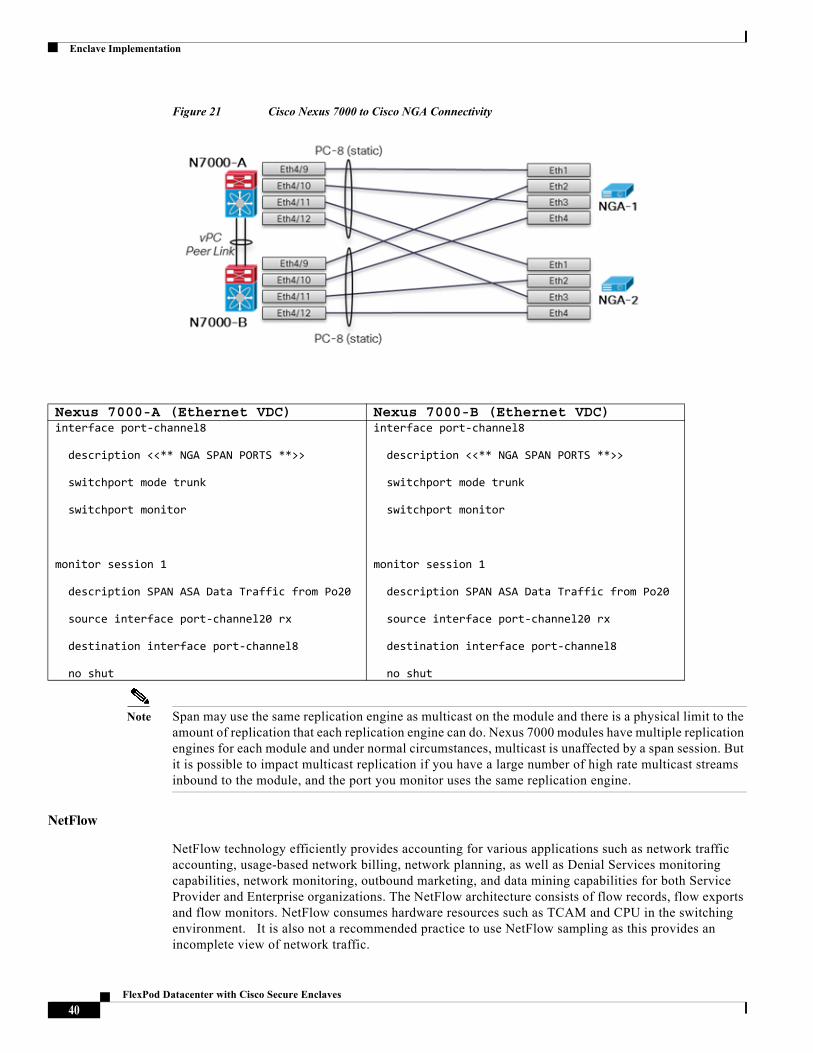
Figure 21 describes the connectivity between the Cisco Nexus 7000 switches and the Cisco NGA devices. Notice that a static port channel is configured on the Cisco Nexus 7000 to the NGAs. The NGA are promiscuous devices and do not participate in port aggregation protocols such as PAGP or LACP on their data interfaces. Each of the links are 10 Gig enabled. The port channel may contain up to 16 active interfaces in the bundle allowing for greater capacity. It is important to note that the NGA devices are independent devices so adding more promiscuous endpoint devices to the port channel is not an issue. SPAN traffic will be redirected and load balanced across the static link members of the port channel.
Nexus 7000-A (Ethernet VDC) Nexus 7000-B (Ethernet VDC) policy-map type qos FP-qos-fas
class class-default
set cos 5
policy-map type qos FP-qos-fas
class class-default
set cos 5
Nexus 7000-A (Storage VDC) Nexus 7000-B (Storage VDC) vlan configuration 201-219
service-policy type qos input FP-qos-fas
vlan configuration 201-219
service-policy type qos input FP-qos-fas
39FlexPod Datacenter with Cisco Secure Enclaves
Enclave Implementation
Figure 21 Cisco Nexus 7000 to Cisco NGA Connectivity
Note Span may use the same replication engine as multicast on the module and there is a physical limit to the amount of replication that each replication engine can do. Nexus 7000 modules have multiple replication engines for each module and under normal circumstances, multicast is unaffected by a span session. But it is possible to impact multicast replication if you have a large number of high rate multicast streams inbound to the module, and the port you monitor uses the same replication engine.
NetFlow
NetFlow technology efficiently provides accounting for various applications such as network traffic accounting, usage-based network billing, network planning, as well as Denial Services monitoring capabilities, network monitoring, outbound marketing, and data mining capabilities for both Service Provider and Enterprise organizations. The NetFlow architecture consists of flow records, flow exports and flow monitors. NetFlow consumes hardware resources such as TCAM and CPU in the switching environment. It is also not a recommended practice to use NetFlow sampling as this provides an incomplete view of network traffic.
Nexus 7000-A (Ethernet VDC) Nexus 7000-B (Ethernet VDC) interface port-channel8
description <<** NGA SPAN PORTS **>>
switchport mode trunk
switchport monitor
monitor session 1
description SPAN ASA Data Traffic from Po20
source interface port-channel20 rx
destination interface port-channel8
no shut
interface port-channel8
description <<** NGA SPAN PORTS **>>
switchport mode trunk
switchport monitor
monitor session 1
description SPAN ASA Data Traffic from Po20
source interface port-channel20 rx
destination interface port-channel8
no shut
40FlexPod Datacenter with Cisco Secure Enclaves
Enclave Implementation
To avoid NetFlow resource utilization in the Nexus switch and potential "blindspots" the NetFlow service is offloaded to dedicated devices, namely the Cisco NetFlow Generation Appliances (NGA). The NGAs consume SPAN traffic from the Nexus 7000. The NGAs are promiscuous endpoints of Port Channel 8 described above. Please see the Cisco NetFlow Generation Appliance section for details on its implementation in the design.
Cisco Nexus 5000 as FlexPod Data Center Switch
The switch used in this FlexPod data center architecture is the Nexus 5548UP model. The base switch configuration is based on the FlexPod Data Center with VMware vSphere deployment model. The following configurations describe significant implementations to realize the secure enclave architecture.
ISE Integration
Two Identity Services Engines are provisioned in a primary secondary configuration for high availability. Each ISE assumes the following personas:
• Administration Node
• Policy Service Node
• Monitoring Node
The ISE provides RADIUS services to each of the Nexus 5000 VDCs which are configured as Network Devices. The Cisco Nexus 5000 configuration is identical to the Cisco Nexus 7000 implementation captured in the Cisco Nexus 7000 ISE Integration section.
Cisco TrustSec
Cisco TrustSec allows security operations teams to create role-based security policy. The Cisco Nexus 5500 platform supports TrustSec but cannot act as an SXP "listener". his means it cannot aggregate and advertise through SXP the IP to SGT mappings learned from the Cisco Nexus 1000v. In light of this, the Nexus 1000v will implement an SXP connection to each ASA virtual context directly to advertise the CTS tag to IP information.
Note The Cisco Nexus 7000 and 5000 support enforcement of Security Group ACLs in the network fabric. This capability was not explored in this design.
Private VLANs
The use of private VLANs allows for the complete isolation of control and management traffic within an Enclave. The Cisco Nexus 5548UP supports private VLANs and used the following structure during validation. In this sample, VLAN 3171 is the primary VLAN and 3172 is an isolated VLAN carried across the infrastructure.
41FlexPod Datacenter with Cisco Secure Enclaves
Enclave Implementation
Port Profiles
A Port profile is a mechanism for simplified configuration of interfaces. A port profile can be assigned to multiple interfaces giving them all the same configuration. Port profiles provide consistency. Changes to the port profile can be propagated automatically to the configuration of any interface assigned to it. Please use the port profile guidance provided in the Nexus 7000 Port Profiles section for configuration details.
Quality of Service (QoS)
The Nexus 5500 platform inherently trusts the CoS values it receives. In the FlexPod Data Center platform the same assumption is made, CoS values are trusted and expected to be properly set prior to egressing the unified computing domain. The NetApp FAS controller traffic will be marked on ingress to the Nexus 5500 platform.
A system class is uniquely identified by a qos-group value. The Nexus 5500 platform supports six classes or qos-groups. qos-group 0 is reserved for default drop traffic. The Nexus 5500 by default assigns all traffic to this class with the exception of FCoE which is reserved for qos-group 1. This essentially leaves groups 2 through 5 for cos mapping. Each qos-group will define policies and attributes to assign to traffic in that class such as MTU, CoS value and bandwidth. The CoS 5 Gold class will be assigned to qos-group 4.
The NAS traffic originating from the NetApp FAS controllers will be classified and marked to receive the appropriate levels of service across the Enclave architecture. The pm-qos-fas policy map was created to mark all packets with a CoS of 5 (Gold). CoS 5 aligns with the policies created in the remaining QoS enabled infrastructure.
The Nexus 5000 supports VLAN based marking. The ability to assign this at the VLAN simplifies the analysis of packets and aligns well with the VLAN to NetApp Storage Virtual Machines (SVMs) relationship which requires dedicated VLANs for processing on the FAS controller. The QoS policy is applied to the appropriate VLANs. After this configuration, the CoS of 5 is effectively marked on all frames within the VLANs listed. The VLANs in this example 201-219 support NFS traffic.
The TCAM tables must be adjusted to support VLAN QoS entries. The limit is user adjustable and should be modified to support the number of CoS 5 (NFS,iSCSI) VLANs required in the environment. The class map cm-qos-fas classifies all IP traffic through the permit "any any" acl-fas ACL as subject to the policy map pm-qos--fas.
Nexus 5000-A Nexus 5000-BFeature private-vlanvlan 3171 name core-services-primary private-vlan primary private-vlan association 3172vlan 3172 name core-services-isolated private-vlan isolated
Feature private-vlanvlan 3171 name core-services-primary private-vlan primary private-vlan association 3172vlan 3172 name core-services-isolated private-vlan isolated
42FlexPod Datacenter with Cisco Secure Enclaves
Enclave Implementation
Note Use the show hardware profile tcam feature qos command to display TCAM resource utilization.
The following configuration speaks to the classifications defined (qos) on the Nexus switch. A class-map defines the CoS value and is subsequently used to assign the CoS to a system class or qos-group through a system assigned policy map pm-qos-global.
Nexus 5000-A Nexus 5000-B hardware profile tcam feature interface-qos limit 20
ip access-list acl-fas
10 permit ip any any
class-map type qos match-any cm-qos-fas
match access-group name acl-fas
policy-map type qos pm-qos-fas
class cm-qos-fas
set qos-group 4
vlan configuration 201-219
service-policy type qos input pm-qos-fas
hardware profile tcam feature interface-qos limit 20
ip access-list acl-fas
10 permit ip any any
class-map type qos match-any cm-qos-fas
match access-group name acl-fas
policy-map type qos pm-qos-fas
class cm-qos-fas
set qos-group 4
vlan configuration 201-219
service-policy type qos input pm-qos-fas
43FlexPod Datacenter with Cisco Secure Enclaves
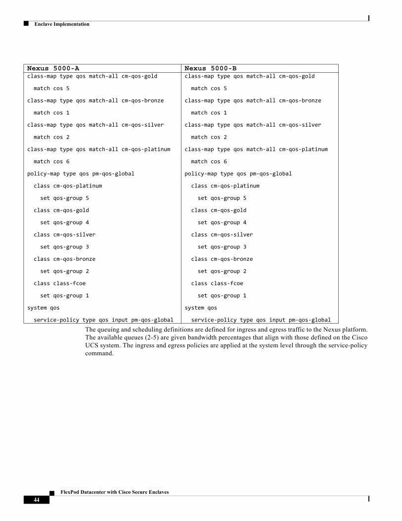
Enclave Implementation
The queuing and scheduling definitions are defined for ingress and egress traffic to the Nexus platform. The available queues (2-5) are given bandwidth percentages that align with those defined on the Cisco UCS system. The ingress and egress policies are applied at the system level through the service-policy command.
Nexus 5000-A Nexus 5000-B class-map type qos match-all cm-qos-gold
match cos 5
class-map type qos match-all cm-qos-bronze
match cos 1
class-map type qos match-all cm-qos-silver
match cos 2
class-map type qos match-all cm-qos-platinum
match cos 6
policy-map type qos pm-qos-global
class cm-qos-platinum
set qos-group 5
class cm-qos-gold
set qos-group 4
class cm-qos-silver
set qos-group 3
class cm-qos-bronze
set qos-group 2
class class-fcoe
set qos-group 1
system qos
service-policy type qos input pm-qos-global
class-map type qos match-all cm-qos-gold
match cos 5
class-map type qos match-all cm-qos-bronze
match cos 1
class-map type qos match-all cm-qos-silver
match cos 2
class-map type qos match-all cm-qos-platinum
match cos 6
policy-map type qos pm-qos-global
class cm-qos-platinum
set qos-group 5
class cm-qos-gold
set qos-group 4
class cm-qos-silver
set qos-group 3
class cm-qos-bronze
set qos-group 2
class class-fcoe
set qos-group 1
system qos
service-policy type qos input pm-qos-global
44FlexPod Datacenter with Cisco Secure Enclaves
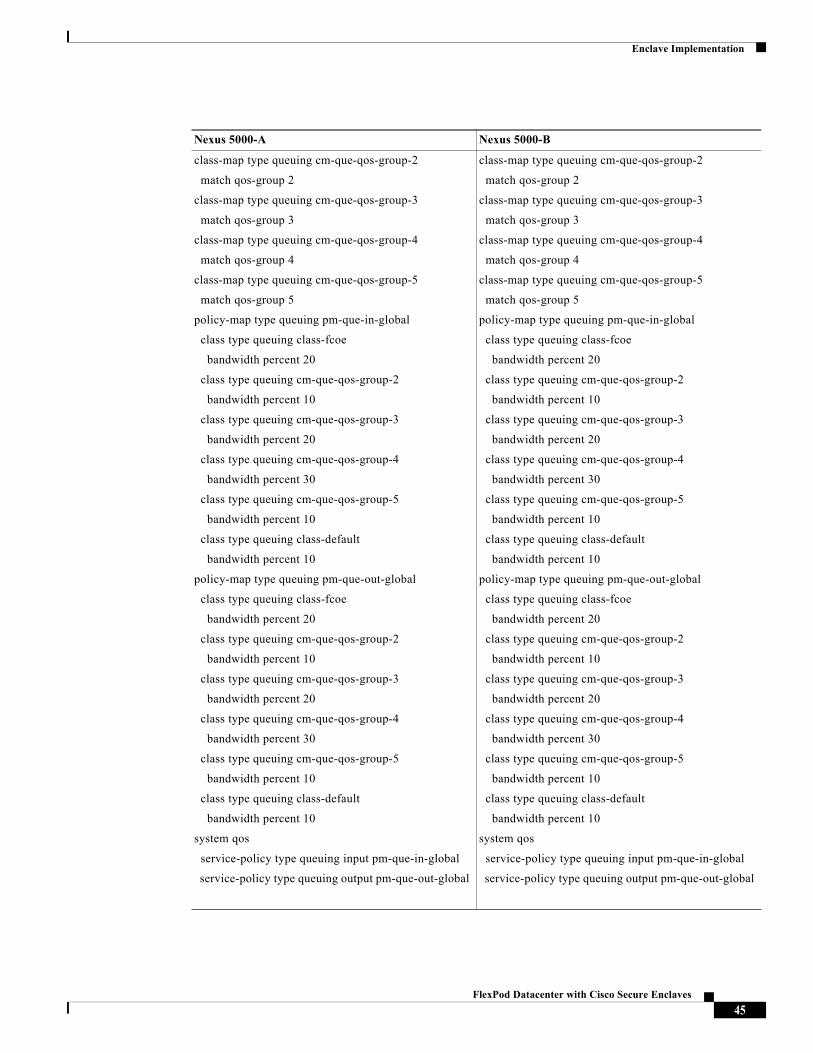
Enclave Implementation
Nexus 5000-A Nexus 5000-B
class-map type queuing cm-que-qos-group-2
match qos-group 2
class-map type queuing cm-que-qos-group-3
match qos-group 3
class-map type queuing cm-que-qos-group-4
match qos-group 4
class-map type queuing cm-que-qos-group-5
match qos-group 5
policy-map type queuing pm-que-in-global
class type queuing class-fcoe
bandwidth percent 20
class type queuing cm-que-qos-group-2
bandwidth percent 10
class type queuing cm-que-qos-group-3
bandwidth percent 20
class type queuing cm-que-qos-group-4
bandwidth percent 30
class type queuing cm-que-qos-group-5
bandwidth percent 10
class type queuing class-default
bandwidth percent 10
policy-map type queuing pm-que-out-global
class type queuing class-fcoe
bandwidth percent 20
class type queuing cm-que-qos-group-2
bandwidth percent 10
class type queuing cm-que-qos-group-3
bandwidth percent 20
class type queuing cm-que-qos-group-4
bandwidth percent 30
class type queuing cm-que-qos-group-5
bandwidth percent 10
class type queuing class-default
bandwidth percent 10
system qos
service-policy type queuing input pm-que-in-global
service-policy type queuing output pm-que-out-global
45FlexPod Datacenter with Cisco Secure Enclaves
Enclave Implementation
The network-qos policy defines the attributes of each qos-group on the Nexus platform. Groups 2 - 5 are each assigned an MTU and associated CoS value. The MTU was set to the maximum in this environment as the edge of the network will define acceptable frame transmission. The fcoe class qos-group 1 is assigned CoS 3 with an MTU of 2518 by default with Priority Flow Control (PFC pause) and lossless Ethernet settings. The network policy is applied at the system level.
46FlexPod Datacenter with Cisco Secure Enclaves
Enclave Implementation
Monitoring
The ability to monitor network traffic within the Nexus platform is key to ensure the efficient operation of the solution. The design calls for the use of Switched Port Analyzer (SPAN) as well as NetFlow services to provide visibility.
Nexus 5000-A Nexus 5000-B class-map type network-qos cm-nq-qos-group-2
match qos-group 2
class-map type network-qos cm-nq-qos-group-3
match qos-group 3
class-map type network-qos cm-nq-qos-group-4
match qos-group 4
class-map type network-qos cm-nq-qos-group-5
match qos-group 5
policy-map type network-qos pm-nq-global
class type network-qos class-fcoe
pause no-drop
mtu 2158
class type network-qos cm-nq-qos-group-5
mtu 9216
set cos 6
class type network-qos cm-nq-qos-group-4
mtu 9216
set cos 5
class type network-qos cm-nq-qos-group-3
mtu 9216
set cos 2
class type network-qos cm-nq-qos-group-2
mtu 9216
set cos 1
system qos
service-policy type network-qos pm-nq-global
class-map type network-qos cm-nq-qos-group-2
match qos-group 2
class-map type network-qos cm-nq-qos-group-3
match qos-group 3
class-map type network-qos cm-nq-qos-group-4
match qos-group 4
class-map type network-qos cm-nq-qos-group-5
match qos-group 5
policy-map type network-qos pm-nq-global
class type network-qos class-fcoe
pause no-drop
mtu 2158
class type network-qos cm-nq-qos-group-5
mtu 9216
set cos 6
class type network-qos cm-nq-qos-group-4
mtu 9216
set cos 5
class type network-qos cm-nq-qos-group-3
mtu 9216
set cos 2
class type network-qos cm-nq-qos-group-2
mtu 9216
set cos 1
system qos
service-policy type network-qos pm-nq-global
47FlexPod Datacenter with Cisco Secure Enclaves
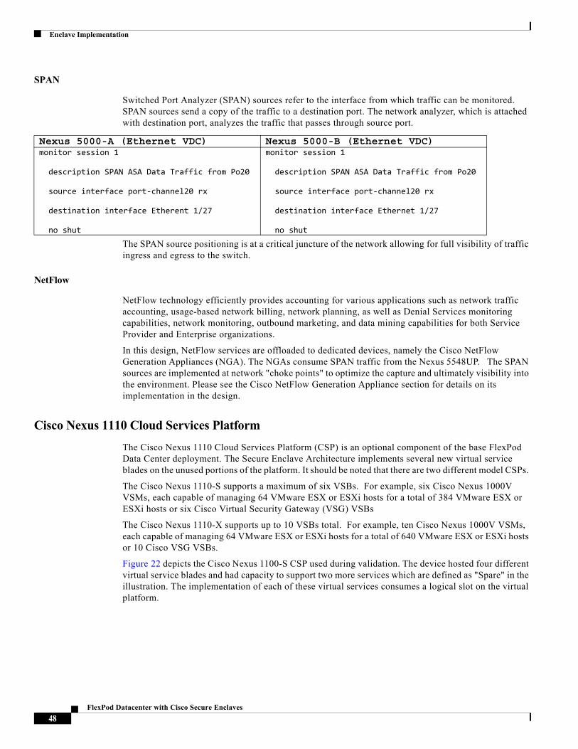
Enclave Implementation
SPAN
Switched Port Analyzer (SPAN) sources refer to the interface from which traffic can be monitored. SPAN sources send a copy of the traffic to a destination port. The network analyzer, which is attached with destination port, analyzes the traffic that passes through source port.
The SPAN source positioning is at a critical juncture of the network allowing for full visibility of traffic ingress and egress to the switch.
NetFlow
NetFlow technology efficiently provides accounting for various applications such as network traffic accounting, usage-based network billing, network planning, as well as Denial Services monitoring capabilities, network monitoring, outbound marketing, and data mining capabilities for both Service Provider and Enterprise organizations.
In this design, NetFlow services are offloaded to dedicated devices, namely the Cisco NetFlow Generation Appliances (NGA). The NGAs consume SPAN traffic from the Nexus 5548UP. The SPAN sources are implemented at network "choke points" to optimize the capture and ultimately visibility into the environment. Please see the Cisco NetFlow Generation Appliance section for details on its implementation in the design.
Cisco Nexus 1110 Cloud Services Platform
The Cisco Nexus 1110 Cloud Services Platform (CSP) is an optional component of the base FlexPod Data Center deployment. The Secure Enclave Architecture implements several new virtual service blades on the unused portions of the platform. It should be noted that there are two different model CSPs.
The Cisco Nexus 1110-S supports a maximum of six VSBs. For example, six Cisco Nexus 1000V VSMs, each capable of managing 64 VMware ESX or ESXi hosts for a total of 384 VMware ESX or ESXi hosts or six Cisco Virtual Security Gateway (VSG) VSBs
The Cisco Nexus 1110-X supports up to 10 VSBs total. For example, ten Cisco Nexus 1000V VSMs, each capable of managing 64 VMware ESX or ESXi hosts for a total of 640 VMware ESX or ESXi hosts or 10 Cisco VSG VSBs.
Figure 22 depicts the Cisco Nexus 1100-S CSP used during validation. The device hosted four different virtual service blades and had capacity to support two more services which are defined as "Spare" in the illustration. The implementation of each of these virtual services consumes a logical slot on the virtual platform.
Nexus 5000-A (Ethernet VDC) Nexus 5000-B (Ethernet VDC) monitor session 1
description SPAN ASA Data Traffic from Po20
source interface port-channel20 rx
destination interface Etherent 1/27
no shut
monitor session 1
description SPAN ASA Data Traffic from Po20
source interface port-channel20 rx
destination interface Ethernet 1/27
no shut
48FlexPod Datacenter with Cisco Secure Enclaves
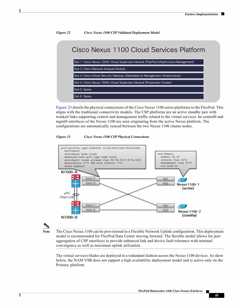
Enclave Implementation
Figure 22 Cisco Nexus 1100 CSP Validated Deployment Model
Figure 23 details the physical connections of the Cisco Nexus 1100 series platforms to the FlexPod. This aligns with the traditional connectivity models. The CSP platforms are an active standby pair with trunked links supporting control and management traffic related to the virtual services. he control0 and mgmt0 interfaces of the Nexus 1100 are seen originating from the active Nexus platform. The configurations are automatically synced between the two Nexus 1100 cluster nodes.
Figure 23 Cisco Nexus 1100 CSP Physical Connections
Note The Cisco Nexus 1100 can be provisioned in a Flexible Network Uplink configuration. This deployment model is recommended for FlexPod Data Center moving forward. The flexible model allows for port aggregation of CSP interfaces to provide enhanced link and device fault tolerance with minimal convergence as well as maximum uplink utilization.
The virtual services blades are deployed in a redundant fashion across the Nexus 1100 devices. As show below, the NAM VSB does not support a high availability deployment model and is active only on the Primary platform.
49FlexPod Datacenter with Cisco Secure Enclaves
Enclave Implementation
Virtual Supervisor Module(s)
The secure enclave architecture uses the base FlexPod Data Center deployment. As such the first virtual service blade in slot ID 1 is already provisioned with the Cisco Nexus Virtual Supervisor Module (VSM) according to the recommended FlexPod practices. This VSM will support infrastructure management services such as VMware vCenter, Microsoft Active Directory services, Cisco ISE among others. The VSM is identified as virtual service blade VSM-1 in the configuration below.
50FlexPod Datacenter with Cisco Secure Enclaves
Enclave Implementation
A second VSM is provisioned to support the application enclaves deployed in the "production" VMware vSphere cluster. The VSM is identified as sea-prod-vsm. The second VSM is not required to isolate the management network infrastructure from the "production" environment but with the available VSB capacity on the Cisco Nexus 1100 platforms it makes the implementation much cleaner. As such, VLAN 3250 provides a dedicated segment for production control traffic.
Virtual Security Gateway
The Virtual Security Gateway (VSG) VSB is dedicated to the protection of the management infrastructure elements. The VSG security policies are built according to the requirements of this infrastructure. Each enclave will have its own VSG with specific security policies for that application environment. Enclave VSGs are provisioned on the "Production" VMware cluster.
Nexus 1100 (Active)virtual-service-blade VSM-1
virtual-service-blade-type name VSM-1.2
interface control vlan 3176
interface packet vlan 3176
ramsize 3072
disksize 3
numcpu 1
cookie 857755331
no shutdown
virtual-service-blade sea-prod-vsm
virtual-service-blade-type name VSM-1.3
interface control vlan 3250
interface packet vlan 3250
ramsize 3072
disksize 3
numcpu 1
cookie 1936577345
no shutdown primary
no shutdown secondary
51FlexPod Datacenter with Cisco Secure Enclaves
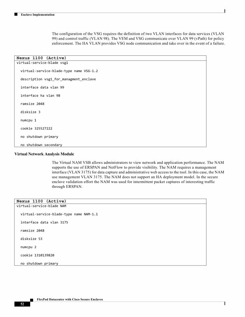
Enclave Implementation
The configuration of the VSG requires the definition of two VLAN interfaces for data services (VLAN 99) and control traffic (VLAN 98). The VEM and VSG communicate over VLAN 99 (vPath) for policy enforcement. The HA VLAN provides VSG node communication and take over in the event of a failure.
Virtual Network Analysis Module
The Virtual NAM VSB allows administrators to view network and application performance. The NAM supports the use of ERSPAN and NetFlow to provide visibility. The NAM requires a management interface (VLAN 3175) for data capture and administrative web access to the tool. In this case, the NAM use management VLAN 3175. The NAM does not support an HA deployment model. In the secure enclave validation effort the NAM was used for intermittent packet captures of interesting traffic through ERSPAN.
Nexus 1100 (Active)virtual-service-blade vsg1
virtual-service-blade-type name VSG-1.2
description vsg1_for_managment_enclave
interface data vlan 99
interface ha vlan 98
ramsize 2048
disksize 3
numcpu 1
cookie 325527222
no shutdown primary
no shutdown secondary
Nexus 1100 (Active)virtual-service-blade NAM
virtual-service-blade-type name NAM-1.1
interface data vlan 3175
ramsize 2048
disksize 53
numcpu 2
cookie 1310139820
no shutdown primary
52FlexPod Datacenter with Cisco Secure Enclaves
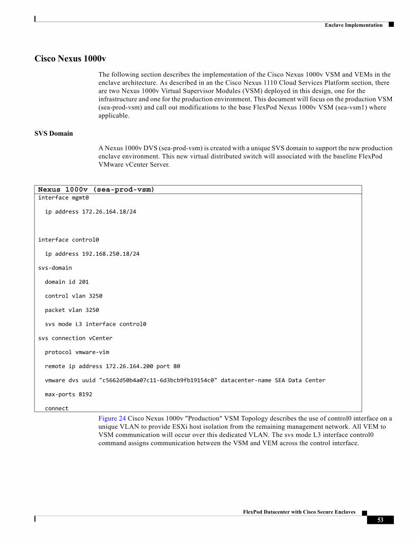
Enclave Implementation
Cisco Nexus 1000v
The following section describes the implementation of the Cisco Nexus 1000v VSM and VEMs in the enclave architecture. As described in an the Cisco Nexus 1110 Cloud Services Platform section, there are two Nexus 1000v Virtual Supervisor Modules (VSM) deployed in this design, one for the infrastructure and one for the production environment. This document will focus on the production VSM (sea-prod-vsm) and call out modifications to the base FlexPod Nexus 1000v VSM (sea-vsm1) where applicable.
SVS Domain
A Nexus 1000v DVS (sea-prod-vsm) is created with a unique SVS domain to support the new production enclave environment. This new virtual distributed switch will associated with the baseline FlexPod VMware vCenter Server.
Figure 24 Cisco Nexus 1000v "Production" VSM Topology describes the use of control0 interface on a unique VLAN to provide ESXi host isolation from the remaining management network. All VEM to VSM communication will occur over this dedicated VLAN. The svs mode L3 interface control0 command assigns communication between the VSM and VEM across the control interface.
Nexus 1000v (sea-prod-vsm)interface mgmt0
ip address 172.26.164.18/24
interface control0
ip address 192.168.250.18/24
svs-domain
domain id 201
control vlan 3250
packet vlan 3250
svs mode L3 interface control0
svs connection vCenter
protocol vmware-vim
remote ip address 172.26.164.200 port 80
vmware dvs uuid "c5662d50b4a07c11-6d3bcb9fb19154c0" datacenter-name SEA Data Center
max-ports 8192
connect
53FlexPod Datacenter with Cisco Secure Enclaves
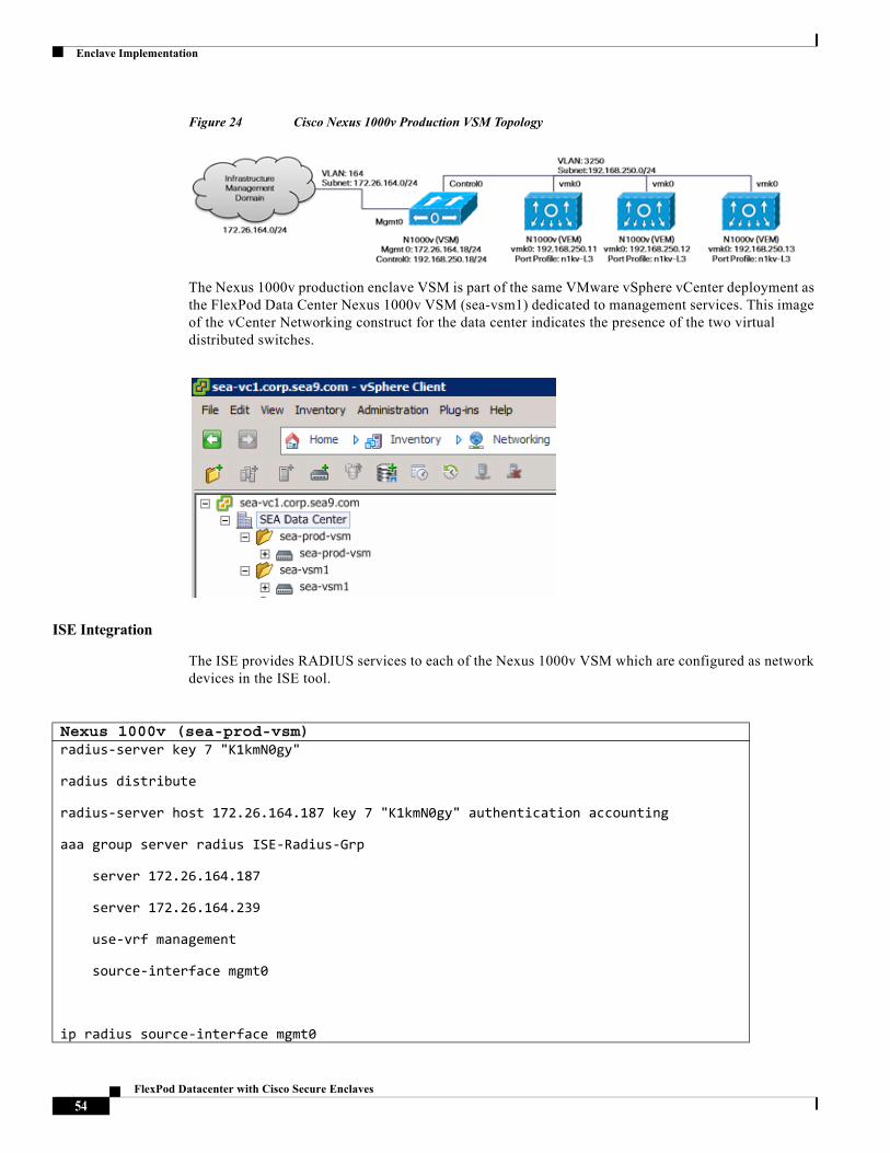
Enclave Implementation
Figure 24 Cisco Nexus 1000v Production VSM Topology
The Nexus 1000v production enclave VSM is part of the same VMware vSphere vCenter deployment as the FlexPod Data Center Nexus 1000v VSM (sea-vsm1) dedicated to management services. This image of the vCenter Networking construct for the data center indicates the presence of the two virtual distributed switches.
ISE Integration
The ISE provides RADIUS services to each of the Nexus 1000v VSM which are configured as network devices in the ISE tool.
Nexus 1000v (sea-prod-vsm)radius-server key 7 "K1kmN0gy"
radius distribute
radius-server host 172.26.164.187 key 7 "K1kmN0gy" authentication accounting
aaa group server radius ISE-Radius-Grp
server 172.26.164.187
server 172.26.164.239
use-vrf management
source-interface mgmt0
ip radius source-interface mgmt0
54FlexPod Datacenter with Cisco Secure Enclaves
Enclave Implementation
For more deployment details on the ISE implementation please go to the Cisco Identity Services Engine section.
The following AAA commands were used:
55FlexPod Datacenter with Cisco Secure Enclaves
Enclave Implementation
VXLAN
Virtual Extensible LAN (VXLAN) allows organizations to scale beyond the 4000 VLAN limit present in traditional switching environments by encapsulating frames MAC frames in IP. This approach allows a single overlay VLAN to support multiple VXLAN segments, simultaneously addressing VLAN scale issues and network segmentation requirements.
In the enclave architecture, the use of VXLAN is enabled through the segmentation feature and the Unicast-only mode was validated. Unicast-only mode distributes a list of IP addresses associated with a particular VXLAN to all Nexus 1000v VEM. Each VEM requires at least one IP/MAC address pair to terminate VXLAN packets. This IP/MAC address pair is known as the VXLAN Tunnel End Point (VTEP) IP/MAC addresses. The distribution MAC feature enables the VSM to distribute a list of MAC to VTEP associations. The combination of these two features eliminates unicast flooding as all MAC addresses are known to all VEMs under the same VSM.
The IP/MAC address that the VTEP uses is configured when you enter the capability vxlan command. You can have a maximum of four VTEPs in a single VEM. The production Nexus 1000v uses VLAN 3253 to support VXLAN traffic. The Ethernet uplink port-profile supporting traffic originating from the enclaves will support the VXLAN VLAN. Notice the MTU of the uplink is large enough to accommodate the additional VXLAN encapsulation header of 50 bytes.
Nexus 1000v (sea-prod-vsm)aaa authentication login default group ISE-Radius-Grp
aaa authentication dot1x default group ISE-Radius-Grp
aaa accounting dot1x default group ISE-Radius-Grp
aaa authorization cts default group ISE-Radius-Grp
aaa accounting default group ISE-Radius-Grp
no aaa user default-role
Nexus 1000v (sea-prod-vsm)feature segmentation
segment mode unicast-only
segment distribution mac
56FlexPod Datacenter with Cisco Secure Enclaves
Enclave Implementation
The VXLAN vethernet port profile uses that capability vxlan to enable the VXLAN functionality on the VMKNIC on the Nexus 1000v VEM.
Nexus 1000v (sea-prod-vsm)vlan 3253
name prod-vtep-vxlan
port-profile type ethernet enclave-data-uplink
vmware port-group
switchport mode trunk
switchport trunk native vlan 2
system mtu 9000
switchport trunk allowed vlan 201-219,666,2001-2019,3001-3019,3175,3253
channel-group auto mode on mac-pinning
no shutdown
system vlan 201-219
state enabled
Nexus 1000v (sea-prod-vsm)port-profile type vethernet vXLAN-VTEP
vmware port-group
switchport mode access
switchport access vlan 3253
capability vxlan
service-policy type qos input Gold
no shutdown
state enabled
57FlexPod Datacenter with Cisco Secure Enclaves
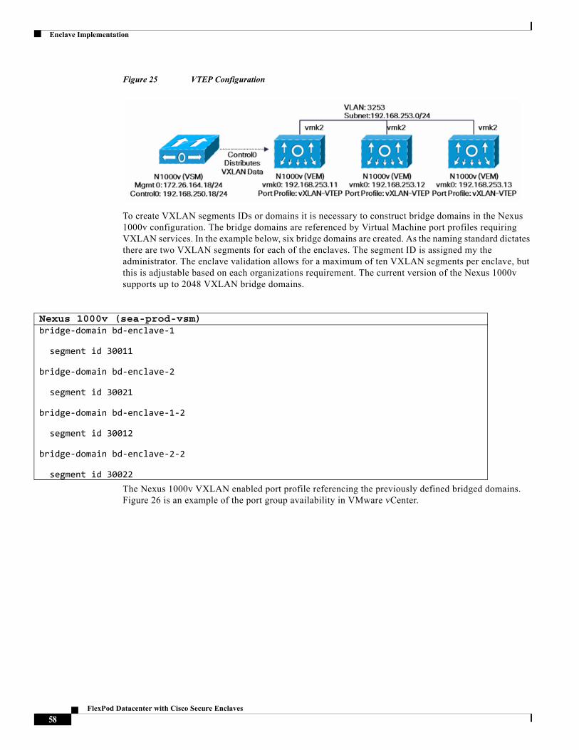
Enclave Implementation
Figure 25 VTEP Configuration
To create VXLAN segments IDs or domains it is necessary to construct bridge domains in the Nexus 1000v configuration. The bridge domains are referenced by Virtual Machine port profiles requiring VXLAN services. In the example below, six bridge domains are created. As the naming standard dictates there are two VXLAN segments for each of the enclaves. The segment ID is assigned my the administrator. The enclave validation allows for a maximum of ten VXLAN segments per enclave, but this is adjustable based on each organizations requirement. The current version of the Nexus 1000v supports up to 2048 VXLAN bridge domains.
The Nexus 1000v VXLAN enabled port profile referencing the previously defined bridged domains. Figure 26 is an example of the port group availability in VMware vCenter.
Nexus 1000v (sea-prod-vsm)bridge-domain bd-enclave-1
segment id 30011
bridge-domain bd-enclave-2
segment id 30021
bridge-domain bd-enclave-1-2
segment id 30012
bridge-domain bd-enclave-2-2
segment id 30022
58FlexPod Datacenter with Cisco Secure Enclaves
Enclave Implementation
Nexus 1000v (sea-prod-vsm)port-profile type vethernet enc1-vxlan1
vmware port-group
inherit port-profile enc-base
switchport access bridge-domain bd-enclave-1
state enabled
port-profile type vethernet enc2-vxlan1
vmware port-group
inherit port-profile enc-base
switchport access bridge-domain bd-enclave-2
state enabled
port-profile type vethernet enc1-vxlan2
vmware port-group
inherit port-profile enc-base
switchport access bridge-domain bd-enclave-1-2
state enabled
port-profile type vethernet enc2-vxlan2
vmware port-group
inherit port-profile enc-base
switchport access bridge-domain bd-enclave-2-2
state enabled
59FlexPod Datacenter with Cisco Secure Enclaves
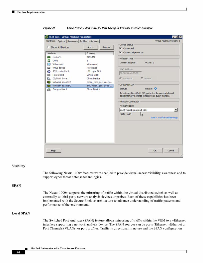
Enclave Implementation
Figure 26 Cisco Nexus 1000v VXLAN Port Group in VMware vCenter Example
Visibility
The following Nexus 1000v features were enabled to provide virtual access visibility, awareness and to support cyber threat defense technologies.
SPAN
The Nexus 1000v supports the mirroring of traffic within the virtual distributed switch as well as externally to third party network analysis devices or probes. Each of these capabilities has been implemented with the Secure Enclave architecture to advance understanding of traffic patterns and performance of the environment.
Local SPAN
The Switched Port Analyzer (SPAN) feature allows mirroring of traffic within the VEM to a vEthernet interface supporting a network analysis device. The SPAN sources can be ports (Ethernet, vEthernet or Port Channels) VLANs, or port profiles. Traffic is directional in nature and the SPAN configuration
60FlexPod Datacenter with Cisco Secure Enclaves
Enclave Implementation
allows for ingress (rx), egress (tx) or both to be captured in relation to the source construct. The following example capture ingress traffic on the system-uplink port-profile and send the data to a promiscuous VM.
Encapsulated Remote SPAN (ERSPAN)
Encapsulated remote (ER) SPAN monitors traffic in multiple network devices across an IP network and sends that traffic in an encapsulated envelope to destination analyzers. In contrast, Local SPAN cannot forward traffic through the IP network. ERSPAN can be used to monitor traffic remotely. ERSPAN sources can be ports (Ethernet, vEthernet or Port Channels) VLANs, or port profiles. The following example show an ERSPAN session capturing traffic from port channel 1 in the Nexus 1000v configuration. The NAM VSB on the Nexus 1100 platform is the destination.
The ERSPAN ID associated with the session is configurable with a maximum of 64 sessions defined. The ERSPAN ID affords filtering at the destination analyzer, in this case example the NAM VSB. Given the replication of traffic with SPAN it is important to note resources on the wire will be consumed an QoS should be properly implemented to avoid negative impacts.
Nexus 1000v (sea-prod-vsm)monitor session 2
source port-profile system-uplink rx
destination interface Vethernet68
no shut
Nexus 1000v (sea-prod-vsm)monitor session 1 type erspan-source
source interface port-channel1 rx
destination ip 172.26.164.167
erspan-id 1
ip ttl 64
ip prec 0
ip dscp 0
mtu 1500
header-type 2
no shut
61FlexPod Datacenter with Cisco Secure Enclaves
Enclave Implementation
NetFlow
The Nexus 1000v supports NetFlow. The data may be exported to the Lancope StealthWatch system for analysis. As shown below the NetFlow feature is enabled. The destination of the flow records is defined as "nf-exprot-1" which is the Lancope Cyber Thread Defense (CTD) solution. The flow record "sea-enclaves" defines the interesting parameters to be captured with each flow and indicates the "nf-export-1" as the collector.
The validated version of the Nexus 1000v supports up to 32 NetFlow monitors and 256 instances. An instance being the application of the monitor to a port-profile. If resource availability is a concern, it is suggested that the monitoring focus on data sources such as data base profiles and critical enclaves within the architecture.
Note For more information on the Cyber Threat Defense system implemented for the Secure Enclave architecture please visit the Cisco Cyber Threat Defense for the Data Center Solution: Cisco Validated Design at www.cisco.com/c/dam/en/us/solutions/collateral/enterprise/design-zone-security/ctd-first-look-design-guide.pdf
Nexus 1000v (sea-prod-vsm)feature netflow
flow exporter nf-export-1
description <<** SEA Lancope Flow Collector **>>
destination 172.26.164.240 use-vrf management
transport udp 2055
source mgmt0
version 9
option exporter-stats timeout 300
option interface-table timeout 300
flow monitor sea-enclaves
record netflow-original
exporter nf-export-1
timeout inactive 15
timeout active 60
62FlexPod Datacenter with Cisco Secure Enclaves
Enclave Implementation
vTracker
The vTracker feature on the Cisco Nexus 1000V switch provides information about the virtual network environment. vTracker provides various views that are based on the data sourced from the vCenter, the Cisco Discovery Protocol (CDP), and other related systems connected with the virtual switch. vTracker enhances troubleshooting, monitoring, and system maintenance. Using vTracker show commands, you can access consolidated network information across the following views:
• Module-View—vTracker showing information about a server module
• upstream-View—vTracker information showing from upstream switch
• Vlan-View—vTracker showing information vlan usage by virtual machines
• Vm-View—vTracker showing information about a virtual machine
• Vmotion-View—vTracker showing information about VM migration
For example the show vtracker module-view provides visibility into the ESXi pNICS defined as vNICS on the Cisco UCS system:
63FlexPod Datacenter with Cisco Secure Enclaves
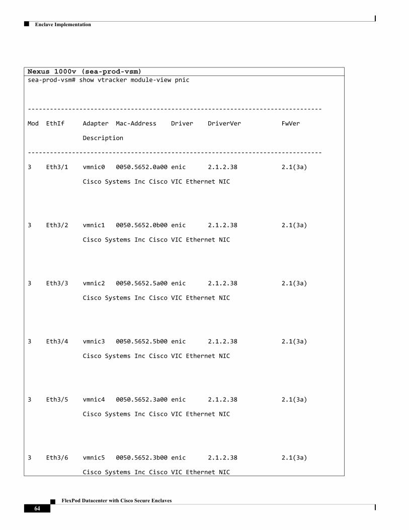
Enclave Implementation
Nexus 1000v (sea-prod-vsm)sea-prod-vsm# show vtracker module-view pnic
--------------------------------------------------------------------------------
Mod EthIf Adapter Mac-Address Driver DriverVer FwVer
Description
--------------------------------------------------------------------------------
3 Eth3/1 vmnic0 0050.5652.0a00 enic 2.1.2.38 2.1(3a)
Cisco Systems Inc Cisco VIC Ethernet NIC
3 Eth3/2 vmnic1 0050.5652.0b00 enic 2.1.2.38 2.1(3a)
Cisco Systems Inc Cisco VIC Ethernet NIC
3 Eth3/3 vmnic2 0050.5652.5a00 enic 2.1.2.38 2.1(3a)
Cisco Systems Inc Cisco VIC Ethernet NIC
3 Eth3/4 vmnic3 0050.5652.5b00 enic 2.1.2.38 2.1(3a)
Cisco Systems Inc Cisco VIC Ethernet NIC
3 Eth3/5 vmnic4 0050.5652.3a00 enic 2.1.2.38 2.1(3a)
Cisco Systems Inc Cisco VIC Ethernet NIC
3 Eth3/6 vmnic5 0050.5652.3b00 enic 2.1.2.38 2.1(3a)
Cisco Systems Inc Cisco VIC Ethernet NIC
64FlexPod Datacenter with Cisco Secure Enclaves
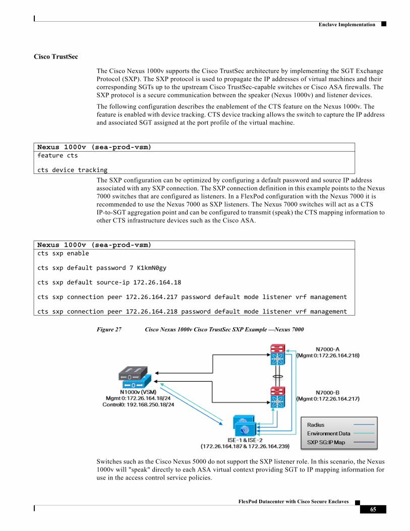
Enclave Implementation
Cisco TrustSec
The Cisco Nexus 1000v supports the Cisco TrustSec architecture by implementing the SGT Exchange Protocol (SXP). The SXP protocol is used to propagate the IP addresses of virtual machines and their corresponding SGTs up to the upstream Cisco TrustSec-capable switches or Cisco ASA firewalls. The SXP protocol is a secure communication between the speaker (Nexus 1000v) and listener devices.
The following configuration describes the enablement of the CTS feature on the Nexus 1000v. The feature is enabled with device tracking. CTS device tracking allows the switch to capture the IP address and associated SGT assigned at the port profile of the virtual machine.
The SXP configuration can be optimized by configuring a default password and source IP address associated with any SXP connection. The SXP connection definition in this example points to the Nexus 7000 switches that are configured as listeners. In a FlexPod configuration with the Nexus 7000 it is recommended to use the Nexus 7000 as SXP listeners. The Nexus 7000 switches will act as a CTS IP-to-SGT aggregation point and can be configured to transmit (speak) the CTS mapping information to other CTS infrastructure devices such as the Cisco ASA.
Figure 27 Cisco Nexus 1000v Cisco TrustSec SXP Example —Nexus 7000
Switches such as the Cisco Nexus 5000 do not support the SXP listener role. In this scenario, the Nexus 1000v will "speak" directly to each ASA virtual context providing SGT to IP mapping information for use in the access control service policies.
Nexus 1000v (sea-prod-vsm)feature cts
cts device tracking
Nexus 1000v (sea-prod-vsm)cts sxp enable
cts sxp default password 7 K1kmN0gy
cts sxp default source-ip 172.26.164.18
cts sxp connection peer 172.26.164.217 password default mode listener vrf management
cts sxp connection peer 172.26.164.218 password default mode listener vrf management
65FlexPod Datacenter with Cisco Secure Enclaves
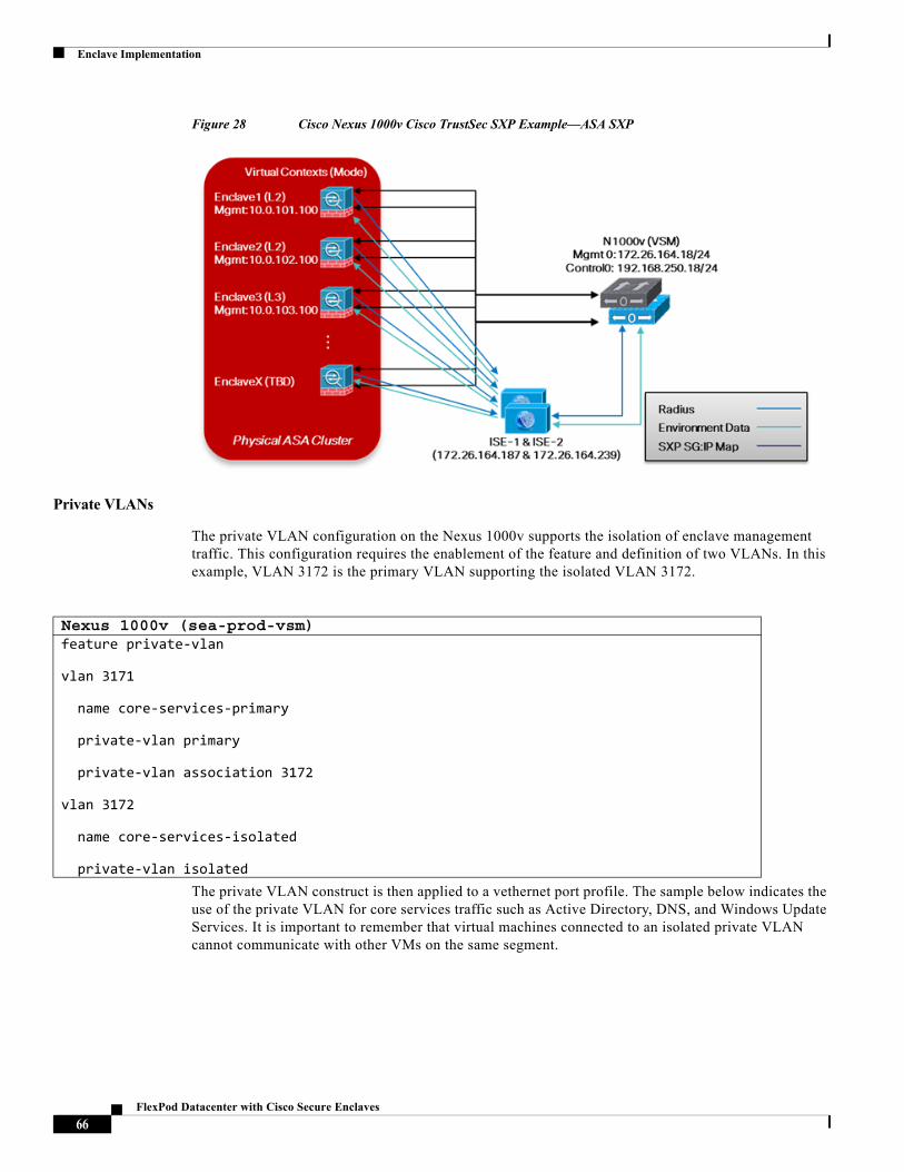
Enclave Implementation
Figure 28 Cisco Nexus 1000v Cisco TrustSec SXP Example—ASA SXP
Private VLANs
The private VLAN configuration on the Nexus 1000v supports the isolation of enclave management traffic. This configuration requires the enablement of the feature and definition of two VLANs. In this example, VLAN 3172 is the primary VLAN supporting the isolated VLAN 3172.
The private VLAN construct is then applied to a vethernet port profile. The sample below indicates the use of the private VLAN for core services traffic such as Active Directory, DNS, and Windows Update Services. It is important to remember that virtual machines connected to an isolated private VLAN cannot communicate with other VMs on the same segment.
Nexus 1000v (sea-prod-vsm)feature private-vlan
vlan 3171
name core-services-primary
private-vlan primary
private-vlan association 3172
vlan 3172
name core-services-isolated
private-vlan isolated
66FlexPod Datacenter with Cisco Secure Enclaves
Enclave Implementation
The Cisco UCS VNICs dedicated to support the private VLAN traffic are assigned to the core-uplink port profile. This port channel trunk carries the primary and isolated VLANs. Notice the primary VLAN is defined as the native VLAN to support traffic coming back from the promiscuous management domain described below.
The isolated private VLAN is also defined on the dedicated infrastructure management Nexus 1000v VSM. The feature and private VLAN definition is identical to the production VSM documented earlier in this section.
Nexus 1000v (sea-prod-vsm)port-profile type vethernet pvlan_core_services
vmware port-group
switchport mode private-vlan host
switchport private-vlan host-association 3171 3172
service-policy type qos input Platinum
no shutdown
state enabled
Nexus 1000v (sea-prod-vsm)port-profile type ethernet core-uplinks
vmware port-group
switchport mode trunk
switchport trunk allowed vlan 3171-3172
system mtu 9000
switchport trunk native vlan 3171
channel-group auto mode on mac-pinning
no shutdown
state enabled
67FlexPod Datacenter with Cisco Secure Enclaves
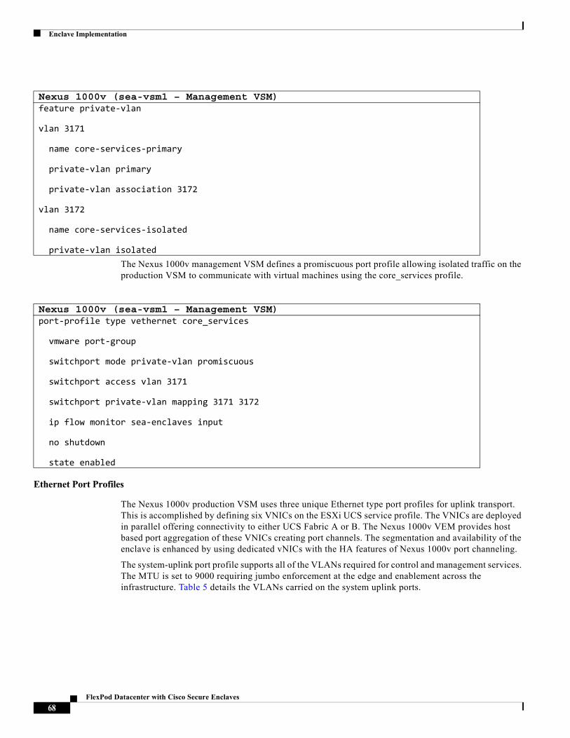
Enclave Implementation
The Nexus 1000v management VSM defines a promiscuous port profile allowing isolated traffic on the production VSM to communicate with virtual machines using the core_services profile.
Ethernet Port Profiles
The Nexus 1000v production VSM uses three unique Ethernet type port profiles for uplink transport. This is accomplished by defining six VNICs on the ESXi UCS service profile. The VNICs are deployed in parallel offering connectivity to either UCS Fabric A or B. The Nexus 1000v VEM provides host based port aggregation of these VNICs creating port channels. The segmentation and availability of the enclave is enhanced by using dedicated vNICs with the HA features of Nexus 1000v port channeling.
The system-uplink port profile supports all of the VLANs required for control and management services. The MTU is set to 9000 requiring jumbo enforcement at the edge and enablement across the infrastructure. Table 5 details the VLANs carried on the system uplink ports.
Nexus 1000v (sea-vsm1 – Management VSM)feature private-vlan
vlan 3171
name core-services-primary
private-vlan primary
private-vlan association 3172
vlan 3172
name core-services-isolated
private-vlan isolated
Nexus 1000v (sea-vsm1 – Management VSM)port-profile type vethernet core_services
vmware port-group
switchport mode private-vlan promiscuous
switchport access vlan 3171
switchport private-vlan mapping 3171 3172
ip flow monitor sea-enclaves input
no shutdown
state enabled
68FlexPod Datacenter with Cisco Secure Enclaves
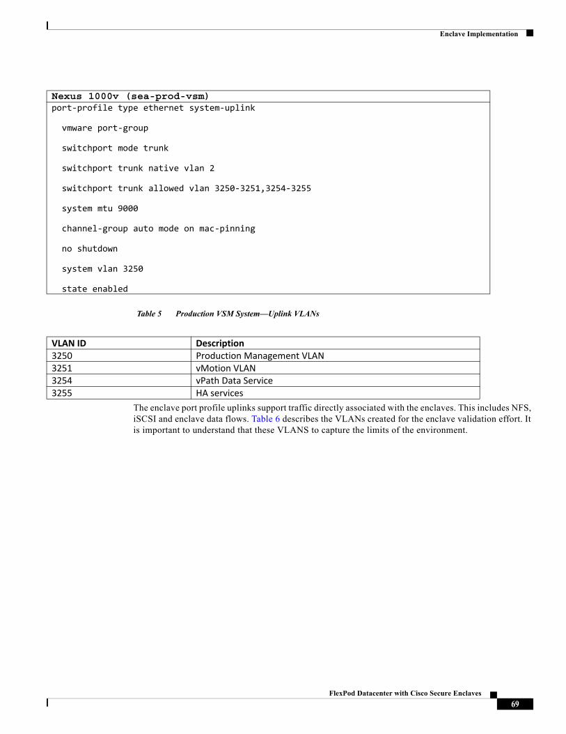
Enclave Implementation
Table 5 Production VSM System—Uplink VLANs
The enclave port profile uplinks support traffic directly associated with the enclaves. This includes NFS, iSCSI and enclave data flows. Table 6 describes the VLANs created for the enclave validation effort. It is important to understand that these VLANS to capture the limits of the environment.
Nexus 1000v (sea-prod-vsm)port-profile type ethernet system-uplink
vmware port-group
switchport mode trunk
switchport trunk native vlan 2
switchport trunk allowed vlan 3250-3251,3254-3255
system mtu 9000
channel-group auto mode on mac-pinning
no shutdown
system vlan 3250
state enabled
VLAN ID Description 3250 Production Management VLAN3251 vMotion VLAN3254 vPath Data Service3255 HA services
69FlexPod Datacenter with Cisco Secure Enclaves
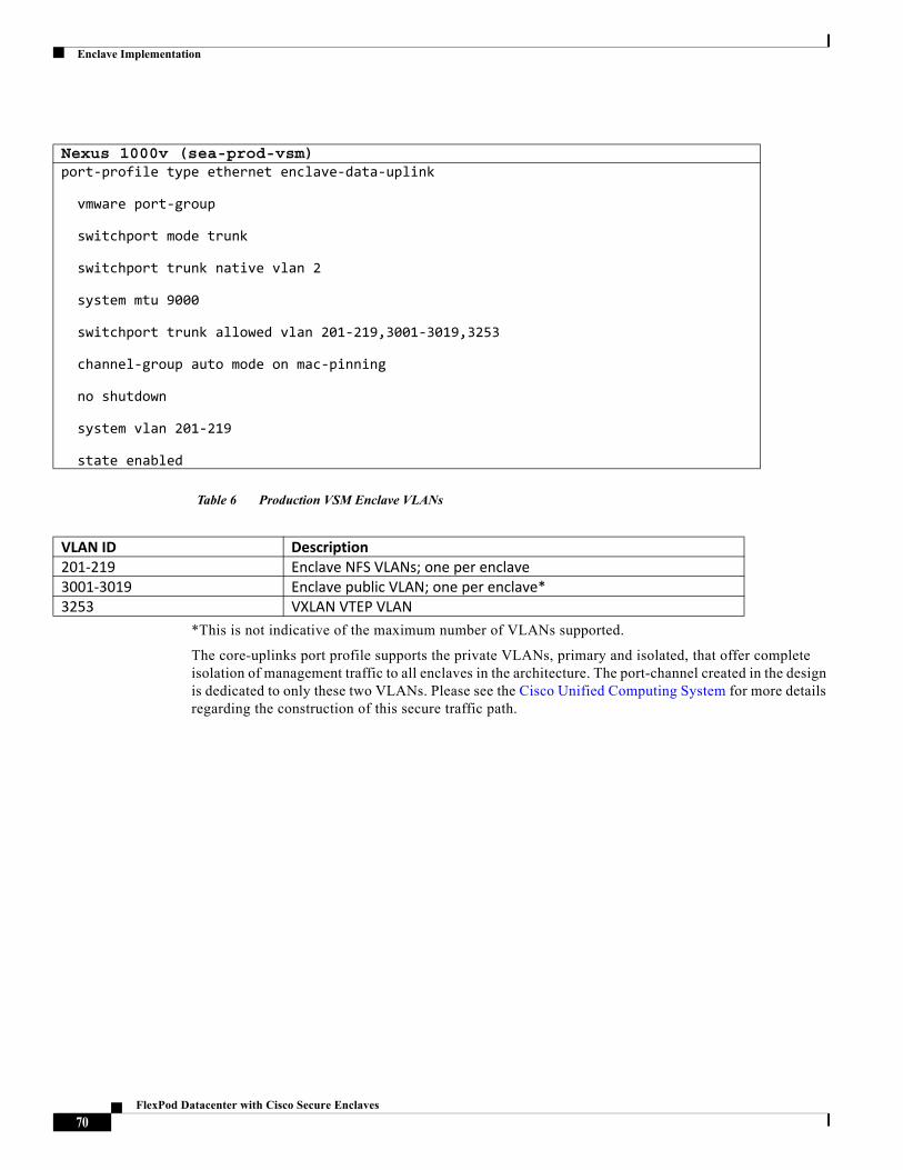
Enclave Implementation
Table 6 Production VSM Enclave VLANs
*This is not indicative of the maximum number of VLANs supported.
The core-uplinks port profile supports the private VLANs, primary and isolated, that offer complete isolation of management traffic to all enclaves in the architecture. The port-channel created in the design is dedicated to only these two VLANs. Please see the Cisco Unified Computing System for more details regarding the construction of this secure traffic path.
Nexus 1000v (sea-prod-vsm)port-profile type ethernet enclave-data-uplink
vmware port-group
switchport mode trunk
switchport trunk native vlan 2
system mtu 9000
switchport trunk allowed vlan 201-219,3001-3019,3253
channel-group auto mode on mac-pinning
no shutdown
system vlan 201-219
state enabled
VLAN ID Description 201-219 Enclave NFS VLANs; one per enclave3001-3019 Enclave public VLAN; one per enclave*3253 VXLAN VTEP VLAN
70FlexPod Datacenter with Cisco Secure Enclaves
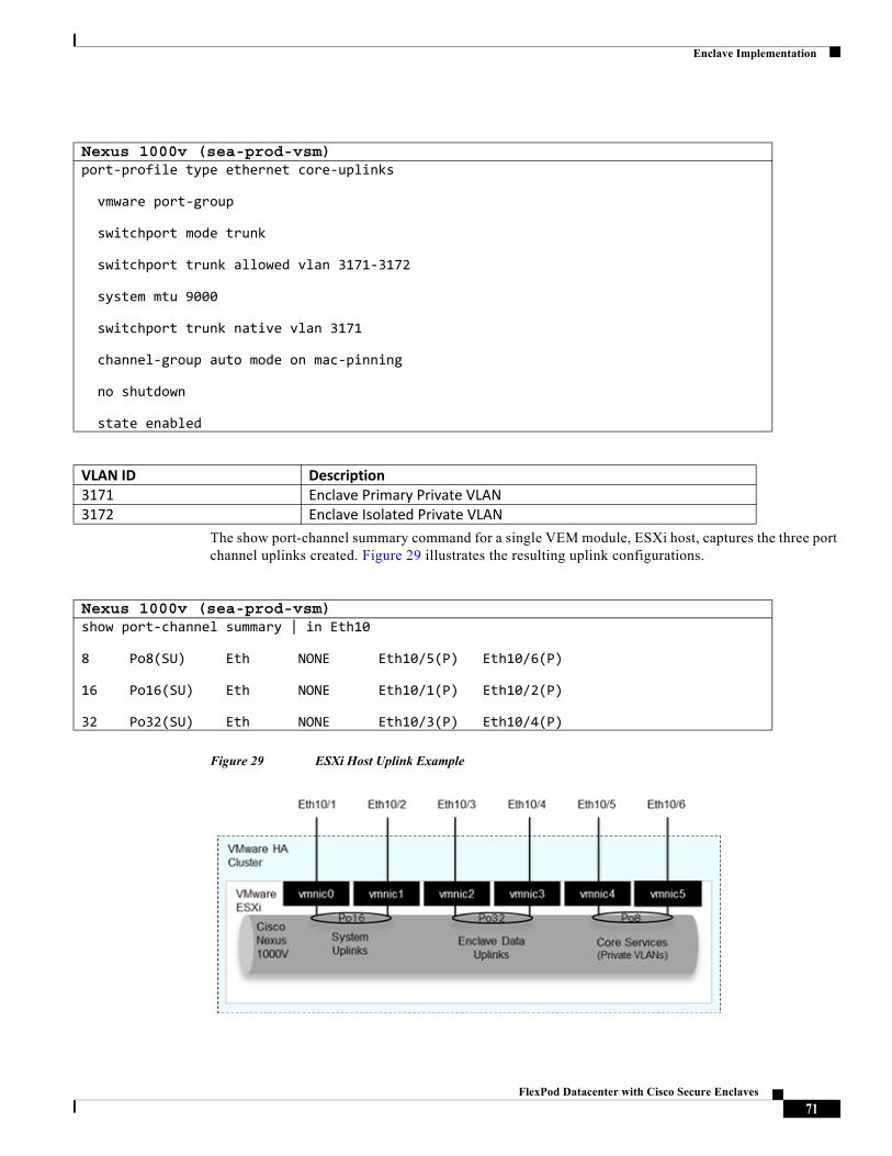
Enclave Implementation
The show port-channel summary command for a single VEM module, ESXi host, captures the three port channel uplinks created. Figure 29 illustrates the resulting uplink configurations.
Figure 29 ESXi Host Uplink Example
Nexus 1000v (sea-prod-vsm)port-profile type ethernet core-uplinks
vmware port-group
switchport mode trunk
switchport trunk allowed vlan 3171-3172
system mtu 9000
switchport trunk native vlan 3171
channel-group auto mode on mac-pinning
no shutdown
state enabled
VLAN ID Description 3171 Enclave Primary Private VLAN3172 Enclave Isolated Private VLAN
Nexus 1000v (sea-prod-vsm)show port-channel summary | in Eth10
8 Po8(SU) Eth NONE Eth10/5(P) Eth10/6(P)
16 Po16(SU) Eth NONE Eth10/1(P) Eth10/2(P)
32 Po32(SU) Eth NONE Eth10/3(P) Eth10/4(P)
71FlexPod Datacenter with Cisco Secure Enclaves
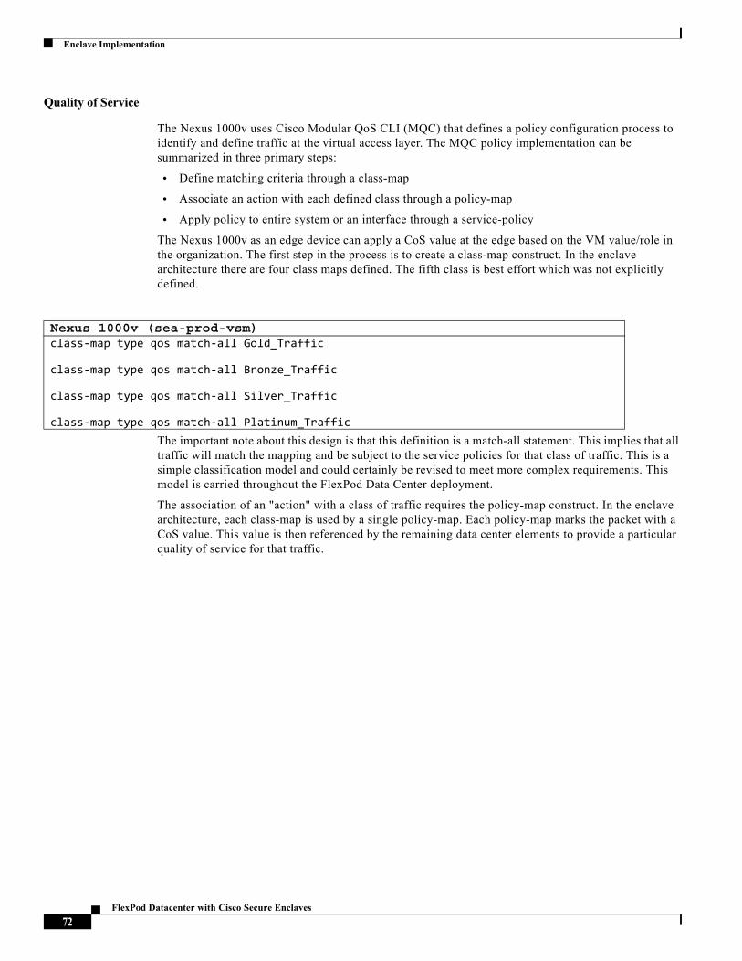
Enclave Implementation
Quality of Service
The Nexus 1000v uses Cisco Modular QoS CLI (MQC) that defines a policy configuration process to identify and define traffic at the virtual access layer. The MQC policy implementation can be summarized in three primary steps:
• Define matching criteria through a class-map
• Associate an action with each defined class through a policy-map
• Apply policy to entire system or an interface through a service-policy
The Nexus 1000v as an edge device can apply a CoS value at the edge based on the VM value/role in the organization. The first step in the process is to create a class-map construct. In the enclave architecture there are four class maps defined. The fifth class is best effort which was not explicitly defined.
The important note about this design is that this definition is a match-all statement. This implies that all traffic will match the mapping and be subject to the service policies for that class of traffic. This is a simple classification model and could certainly be revised to meet more complex requirements. This model is carried throughout the FlexPod Data Center deployment.
The association of an "action" with a class of traffic requires the policy-map construct. In the enclave architecture, each class-map is used by a single policy-map. Each policy-map marks the packet with a CoS value. This value is then referenced by the remaining data center elements to provide a particular quality of service for that traffic.
Nexus 1000v (sea-prod-vsm)class-map type qos match-all Gold_Traffic
class-map type qos match-all Bronze_Traffic
class-map type qos match-all Silver_Traffic
class-map type qos match-all Platinum_Traffic
72FlexPod Datacenter with Cisco Secure Enclaves
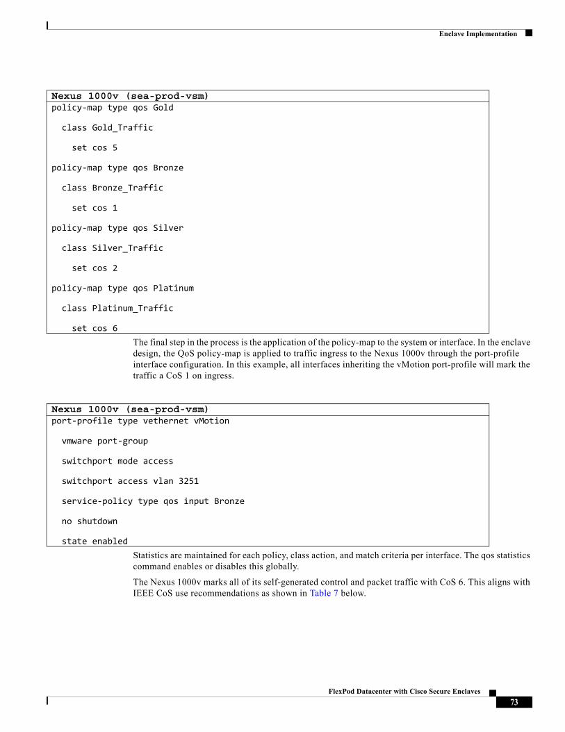
Enclave Implementation
The final step in the process is the application of the policy-map to the system or interface. In the enclave design, the QoS policy-map is applied to traffic ingress to the Nexus 1000v through the port-profile interface configuration. In this example, all interfaces inheriting the vMotion port-profile will mark the traffic a CoS 1 on ingress.
Statistics are maintained for each policy, class action, and match criteria per interface. The qos statistics command enables or disables this globally.
The Nexus 1000v marks all of its self-generated control and packet traffic with CoS 6. This aligns with IEEE CoS use recommendations as shown in Table 7 below.
Nexus 1000v (sea-prod-vsm)policy-map type qos Gold
class Gold_Traffic
set cos 5
policy-map type qos Bronze
class Bronze_Traffic
set cos 1
policy-map type qos Silver
class Silver_Traffic
set cos 2
policy-map type qos Platinum
class Platinum_Traffic
set cos 6
Nexus 1000v (sea-prod-vsm)port-profile type vethernet vMotion
vmware port-group
switchport mode access
switchport access vlan 3251
service-policy type qos input Bronze
no shutdown
state enabled
73FlexPod Datacenter with Cisco Secure Enclaves
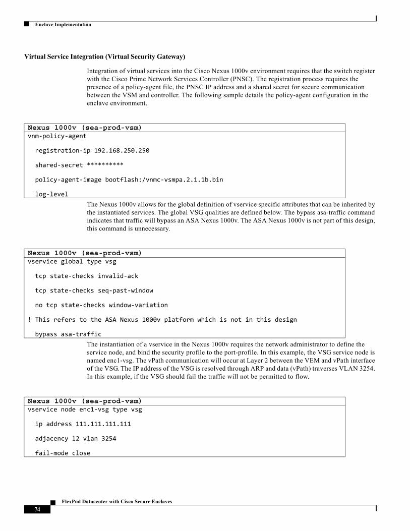
Enclave Implementation
Virtual Service Integration (Virtual Security Gateway)
Integration of virtual services into the Cisco Nexus 1000v environment requires that the switch register with the Cisco Prime Network Services Controller (PNSC). The registration process requires the presence of a policy-agent file, the PNSC IP address and a shared secret for secure communication between the VSM and controller. The following sample details the policy-agent configuration in the enclave environment.
The Nexus 1000v allows for the global definition of vservice specific attributes that can be inherited by the instantiated services. The global VSG qualities are defined below. The bypass asa-traffic command indicates that traffic will bypass an ASA Nexus 1000v. The ASA Nexus 1000v is not part of this design, this command is unnecessary.
The instantiation of a vservice in the Nexus 1000v requires the network administrator to define the service node, and bind the security profile to the port-profile. In this example, the VSG service node is named enc1-vsg. The vPath communication will occur at Layer 2 between the VEM and vPath interface of the VSG. The IP address of the VSG is resolved through ARP and data (vPath) traverses VLAN 3254. In this example, if the VSG should fail the traffic will not be permitted to flow.
Nexus 1000v (sea-prod-vsm)vnm-policy-agent
registration-ip 192.168.250.250
shared-secret **********
policy-agent-image bootflash:/vnmc-vsmpa.2.1.1b.bin
log-level
Nexus 1000v (sea-prod-vsm)vservice global type vsg
tcp state-checks invalid-ack
tcp state-checks seq-past-window
no tcp state-checks window-variation
! This refers to the ASA Nexus 1000v platform which is not in this design
bypass asa-traffic
Nexus 1000v (sea-prod-vsm)vservice node enc1-vsg type vsg
ip address 111.111.111.111
adjacency l2 vlan 3254
fail-mode close
74FlexPod Datacenter with Cisco Secure Enclaves
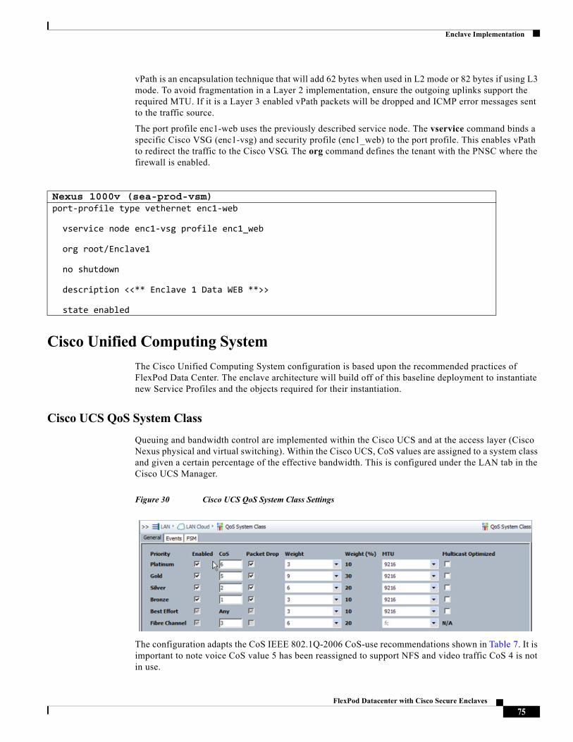
Enclave Implementation
vPath is an encapsulation technique that will add 62 bytes when used in L2 mode or 82 bytes if using L3 mode. To avoid fragmentation in a Layer 2 implementation, ensure the outgoing uplinks support the required MTU. If it is a Layer 3 enabled vPath packets will be dropped and ICMP error messages sent to the traffic source.
The port profile enc1-web uses the previously described service node. The vservice command binds a specific Cisco VSG (enc1-vsg) and security profile (enc1_web) to the port profile. This enables vPath to redirect the traffic to the Cisco VSG. The org command defines the tenant with the PNSC where the firewall is enabled.
Cisco Unified Computing System
The Cisco Unified Computing System configuration is based upon the recommended practices of FlexPod Data Center. The enclave architecture will build off of this baseline deployment to instantiate new Service Profiles and the objects required for their instantiation.
Cisco UCS QoS System Class
Queuing and bandwidth control are implemented within the Cisco UCS and at the access layer (Cisco Nexus physical and virtual switching). Within the Cisco UCS, CoS values are assigned to a system class and given a certain percentage of the effective bandwidth. This is configured under the LAN tab in the Cisco UCS Manager.
Figure 30 Cisco UCS QoS System Class Settings
The configuration adapts the CoS IEEE 802.1Q-2006 CoS-use recommendations shown in Table 7. It is important to note voice CoS value 5 has been reassigned to support NFS and video traffic CoS 4 is not in use.
Nexus 1000v (sea-prod-vsm)port-profile type vethernet enc1-web
vservice node enc1-vsg profile enc1_web
org root/Enclave1
no shutdown
description <<** Enclave 1 Data WEB **>>
state enabled
75FlexPod Datacenter with Cisco Secure Enclaves
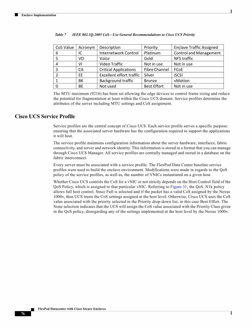
Enclave Implementation
Table 7 IEEE 802.1Q-2005 CoS—Use General Recommendations to Cisco UCS Priority
The MTU maximum (9216) has been set allowing the edge devices to control frame sizing and reduce the potential for fragmentation at least within the Cisco UCS domain. Service profiles determine the attributes of the server including MTU settings and CoS assignment.
Cisco UCS Service Profile
Service profiles are the central concept of Cisco UCS. Each service profile serves a specific purpose: ensuring that the associated server hardware has the configuration required to support the applications it will host.
The service profile maintains configuration information about the server hardware, interfaces, fabric connectivity, and server and network identity. This information is stored in a format that you can manage through Cisco UCS Manager. All service profiles are centrally managed and stored in a database on the fabric interconnect.
Every server must be associated with a service profile. The FlexPod Data Center baseline service profiles were used to build the enclave environment. Modifications were made in regards to the QoS policy of the service profiles, as well as, the number of VNICs instantiated on a given host.
Whether Cisco UCS controls the CoS for a vNIC or not strictly depends on the Host Control field of the QoS Policy, which is assigned to that particular vNIC. Referring to Figure 31, the QoS_N1k policy allows full host control. Since Full is selected and if the packet has a valid CoS assigned by the Nexus 1000v, then UCS trusts the CoS settings assigned at the host level. Otherwise, Cisco UCS uses the CoS value associated with the priority selected in the Priority drop-down list, in this case Best Effort. The None selection indicates that the UCS will assign the CoS value associated with the Priority Class given in the QoS policy, disregarding any of the settings implemented at the host level by the Nexus 1000v.
CoS Value Acronym Description Priority Enclave Traffic Assigned6 IC Internetwork Control Platinum Control and Management 5 VO Voice Gold NFS traffic 4 VI Video Traffic Not in use Not in use3 CA Critical Applications Fibre Channel FCoE2 EE Excellent effort traffic Silver iSCSI1 BK Background traffic Bronze vMotion0 BE Not used Best Effort Not in use
76FlexPod Datacenter with Cisco Secure Enclaves
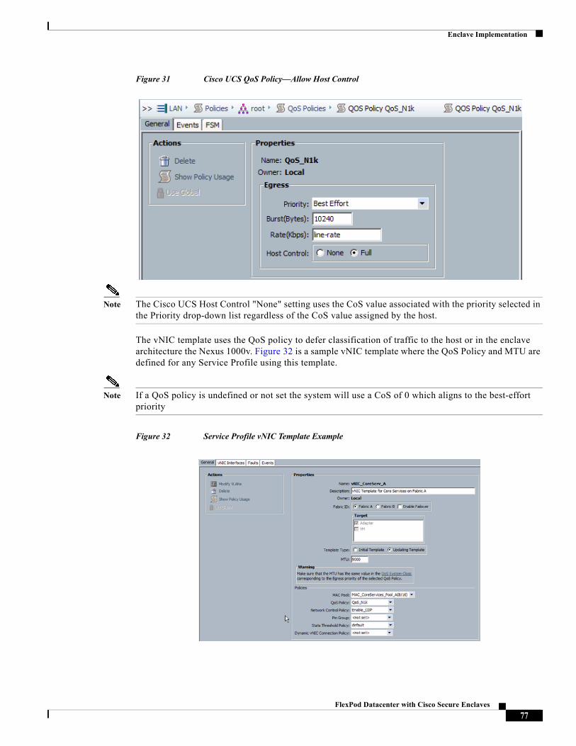
Enclave Implementation
Figure 31 Cisco UCS QoS Policy—Allow Host Control
Note The Cisco UCS Host Control "None" setting uses the CoS value associated with the priority selected in the Priority drop-down list regardless of the CoS value assigned by the host.
The vNIC template uses the QoS policy to defer classification of traffic to the host or in the enclave architecture the Nexus 1000v. Figure 32 is a sample vNIC template where the QoS Policy and MTU are defined for any Service Profile using this template.
Note If a QoS policy is undefined or not set the system will use a CoS of 0 which aligns to the best-effort priority
Figure 32 Service Profile vNIC Template Example
77FlexPod Datacenter with Cisco Secure Enclaves
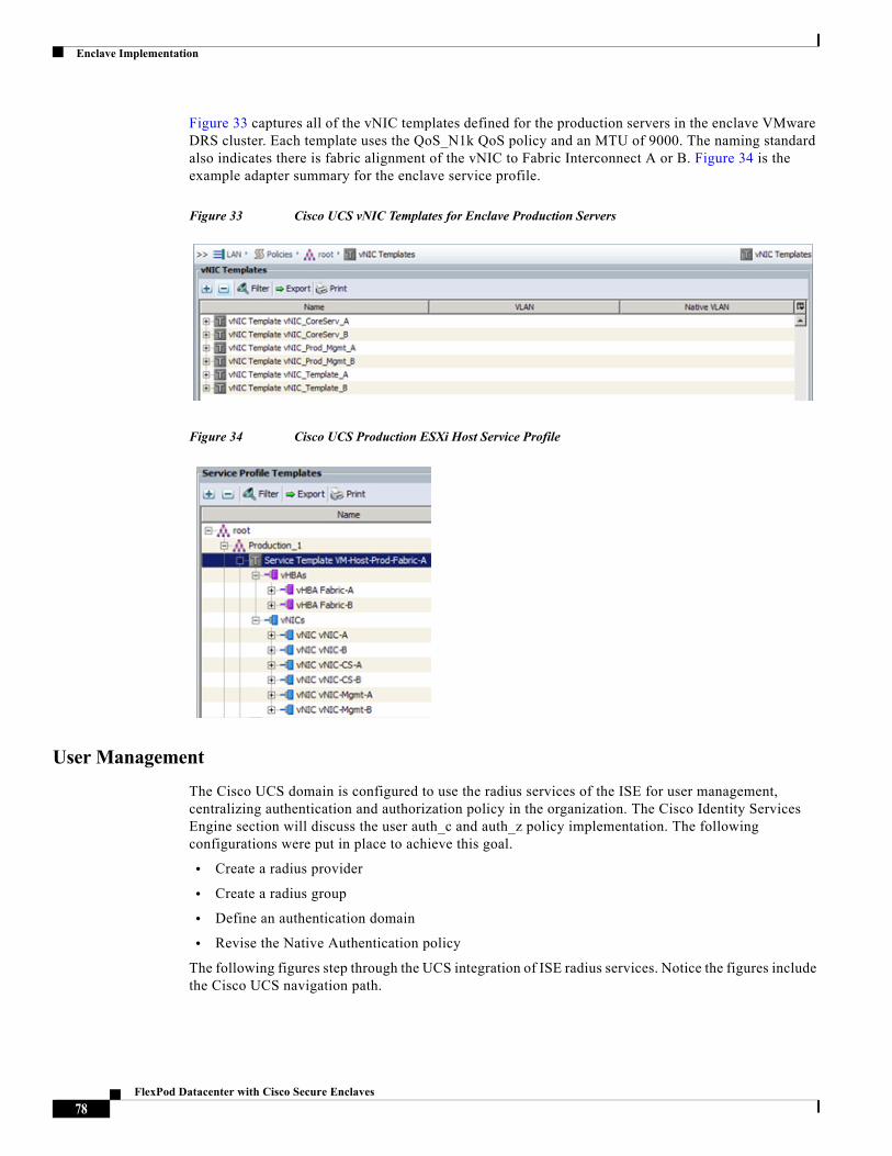
Enclave Implementation
Figure 33 captures all of the vNIC templates defined for the production servers in the enclave VMware DRS cluster. Each template uses the QoS_N1k QoS policy and an MTU of 9000. The naming standard also indicates there is fabric alignment of the vNIC to Fabric Interconnect A or B. Figure 34 is the example adapter summary for the enclave service profile.
Figure 33 Cisco UCS vNIC Templates for Enclave Production Servers
Figure 34 Cisco UCS Production ESXi Host Service Profile
User Management
The Cisco UCS domain is configured to use the radius services of the ISE for user management, centralizing authentication and authorization policy in the organization. The Cisco Identity Services Engine section will discuss the user auth_c and auth_z policy implementation. The following configurations were put in place to achieve this goal.
• Create a radius provider
• Create a radius group
• Define an authentication domain
• Revise the Native Authentication policy
The following figures step through the UCS integration of ISE radius services. Notice the figures include the Cisco UCS navigation path.
78FlexPod Datacenter with Cisco Secure Enclaves
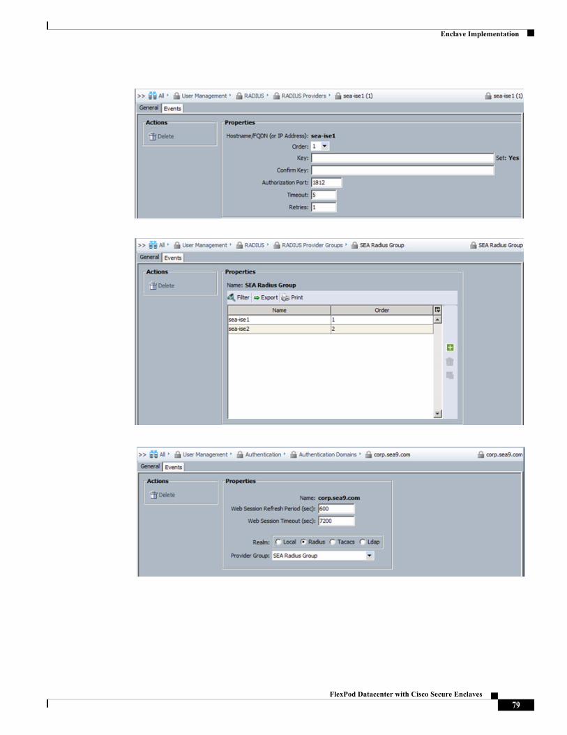
Enclave Implementation
79FlexPod Datacenter with Cisco Secure Enclaves
Enclave Implementation
VMware vSphere
ESXi
The ESXi hosts are uniform in their deployment employing the FCoE boot practices established in FlexPod. The Cisco UCS service profile is altered to provides 6 vmnics for use by the hypervisor as described in the previous section. The following sample from one of the ESXi hosts reflects the UCS VNIC construct and MTU settings provided by the Cisco Nexus 1000v.
The vmknics vmko, vmk1 and vmk2 are provisioned for infrastructure services management, vMotion and VXLAN VTEP respectively. Notice the MTU on the VXLAN services is set to 1700 to account for the encapsulation overhead of VXLAN.
ESXi Host Example~ # esxcfg-nics -l
Name PCI Driver Link Speed Duplex MAC Address MTU Description
vmnic0 0000:06:00.00 enic Up 40000Mbps Full 00:25:b5:02:0a:04 9000 Cisco Systems Inc Cisco VIC Ethernet NIC
vmnic1 0000:07:00.00 enic Up 40000Mbps Full 00:25:b5:02:0b:04 9000 Cisco Systems Inc Cisco VIC Ethernet NIC
vmnic2 0000:08:00.00 enic Up 40000Mbps Full 00:25:b5:02:5a:04 9000 Cisco Systems Inc Cisco VIC Ethernet NIC
vmnic3 0000:09:00.00 enic Up 40000Mbps Full 00:25:b5:02:5b:04 9000 Cisco Systems Inc Cisco VIC Ethernet NIC
vmnic4 0000:0a:00.00 enic Up 40000Mbps Full 00:25:b5:02:3a:04 9000 Cisco Systems Inc Cisco VIC Ethernet NIC
vmnic5 0000:0b:00.00 enic Up 40000Mbps Full 00:25:b5:02:3b:04 9000 Cisco Systems Inc Cisco VIC Ethernet NIC
ESXi Host Example – vmknics for infrastructure services# esxcfg-vmknic -l
Interface Port Group/DVPort IP Family IP Address Netmask Broadcast MAC Address MTU TSO MSS Enabled Type
vmk0 38 IPv4 192.168.250.15 255.255.255.0 192.168.250.255 00:25:b5:02:3a:04 1500 65535 true STATIC
vmk1 740 IPv4 192.168.251.15 255.255.255.0 192.168.251.255 00:50:56:61:64:70 9000 65535 true STATIC
vmk2 776 IPv4 192.168.253.15 255.255.255.0 192.168.253.255 00:50:56:6d:88:95 1700 65535 true STATIC
80FlexPod Datacenter with Cisco Secure Enclaves
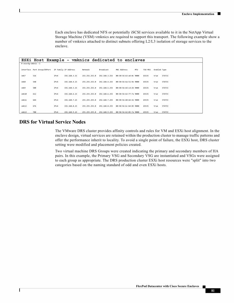
Enclave Implementation
Each enclave has dedicated NFS or potentially iSCSI services available to it in the NetApp Virtual Storage Machine (VSM) vmknics are required to support this transport. The following example show a number of vmknics attached to distinct subnets offering L2/L3 isolation of storage services to the enclave.
DRS for Virtual Service Nodes
The VMware DRS cluster provides affinity controls and rules for VM and ESXi host alignment. In the enclave design, virtual services are retained within the production cluster to manage traffic patterns and offer the performance inherit to locality. To avoid a single point of failure, the ESXi host, DRS cluster setting were modified and placement policies created.
Two virtual machine DRS Groups were created indicating the primary and secondary members of HA pairs. In this example, the Primary VSG and Secondary VSG are instantiated and VSGs were assigned to each group as appropriate. The DRS production cluster ESXi host resources were "split" into two categories based on the naming standard of odd and even ESXi hosts.
ESXi Host Example – vmknics dedicated to enclaves# esxcfg-vmknic -l
Interface Port Group/DVPort IP Family IP Address Netmask Broadcast MAC Address MTU TSO MSS Enabled Type
vmk7 516 IPv4 192.168.3.15 255.255.255.0 192.168.3.255 00:50:56:63:a4:0c 9000 65535 true STATIC
vmk8 548 IPv4 192.168.4.15 255.255.255.0 192.168.4.255 00:50:56:6a:51:9e 9000 65535 true STATIC
vmk9 580 IPv4 192.168.5.15 255.255.255.0 192.168.5.255 00:50:56:64:cd:2b 9000 65535 true STATIC
vmk10 612 IPv4 192.168.6.15 255.255.255.0 192.168.6.255 00:50:56:62:77:7a 9000 65535 true STATIC
vmk11 644 IPv4 192.168.7.15 255.255.255.0 192.168.7.255 00:50:56:68:64:41 9000 65535 true STATIC
vmk12 676 IPv4 192.168.8.15 255.255.255.0 192.168.8.255 00:50:56:6c:b4:85 9000 65535 true STATIC
vmk13 708 IPv4 192.168.9.15 255.255.255.0 192.168.9.255 00:50:56:62:05:7a 9000 65535 true STATIC
81FlexPod Datacenter with Cisco Secure Enclaves
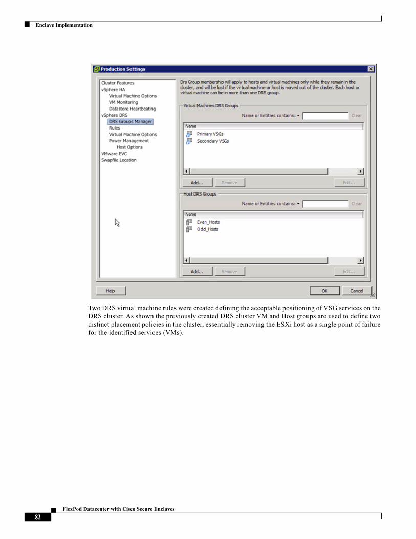
Enclave Implementation
Two DRS virtual machine rules were created defining the acceptable positioning of VSG services on the DRS cluster. As shown the previously created DRS cluster VM and Host groups are used to define two distinct placement policies in the cluster, essentially removing the ESXi host as a single point of failure for the identified services (VMs).
82FlexPod Datacenter with Cisco Secure Enclaves
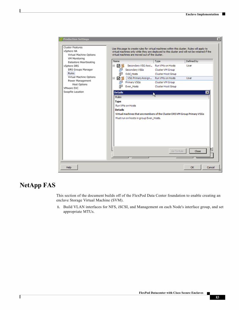
Enclave Implementation
NetApp FAS
This section of the document builds off of the FlexPod Data Center foundation to enable creating an enclave Storage Virtual Machine (SVM).
1. Build VLAN interfaces for NFS, iSCSI, and Management on each Node's interface group, and set appropriate MTUs.
83FlexPod Datacenter with Cisco Secure Enclaves
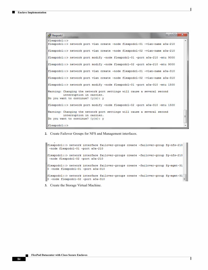
Enclave Implementation
2. Create Failover Groups for NFS and Management interfaces.
3. Create the Storage Virtual Machine.
84FlexPod Datacenter with Cisco Secure Enclaves
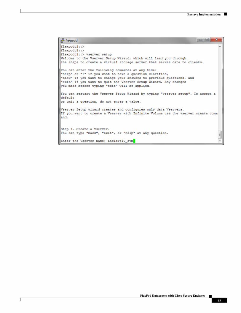
Enclave Implementation
85FlexPod Datacenter with Cisco Secure Enclaves
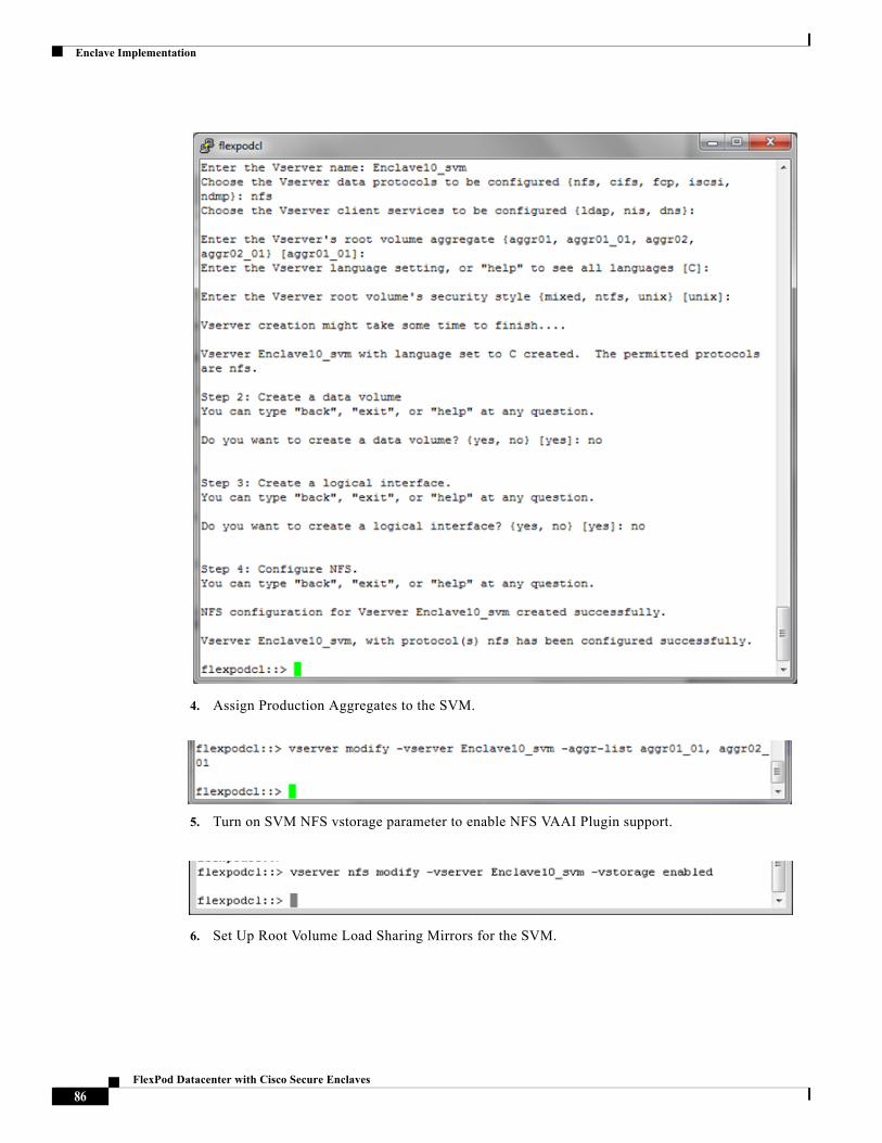
Enclave Implementation
4. Assign Production Aggregates to the SVM.
5. Turn on SVM NFS vstorage parameter to enable NFS VAAI Plugin support.
6. Set Up Root Volume Load Sharing Mirrors for the SVM.
86FlexPod Datacenter with Cisco Secure Enclaves
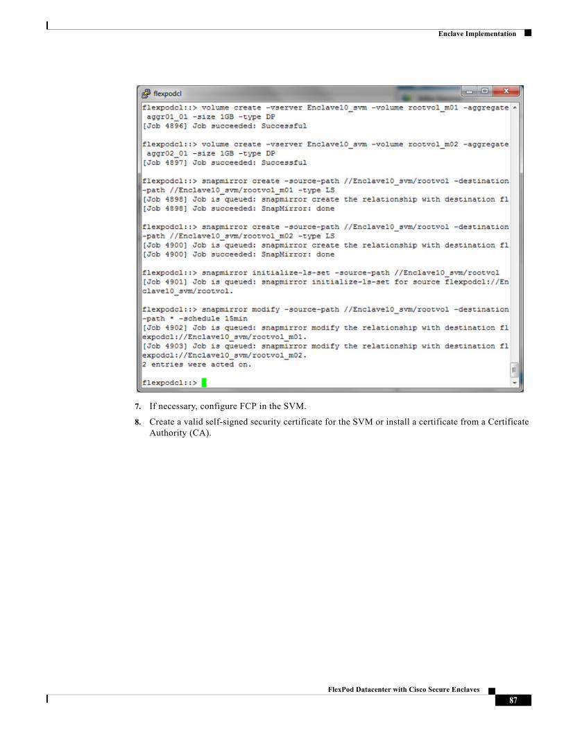
Enclave Implementation
7. If necessary, configure FCP in the SVM.
8. Create a valid self-signed security certificate for the SVM or install a certificate from a Certificate Authority (CA).
87FlexPod Datacenter with Cisco Secure Enclaves
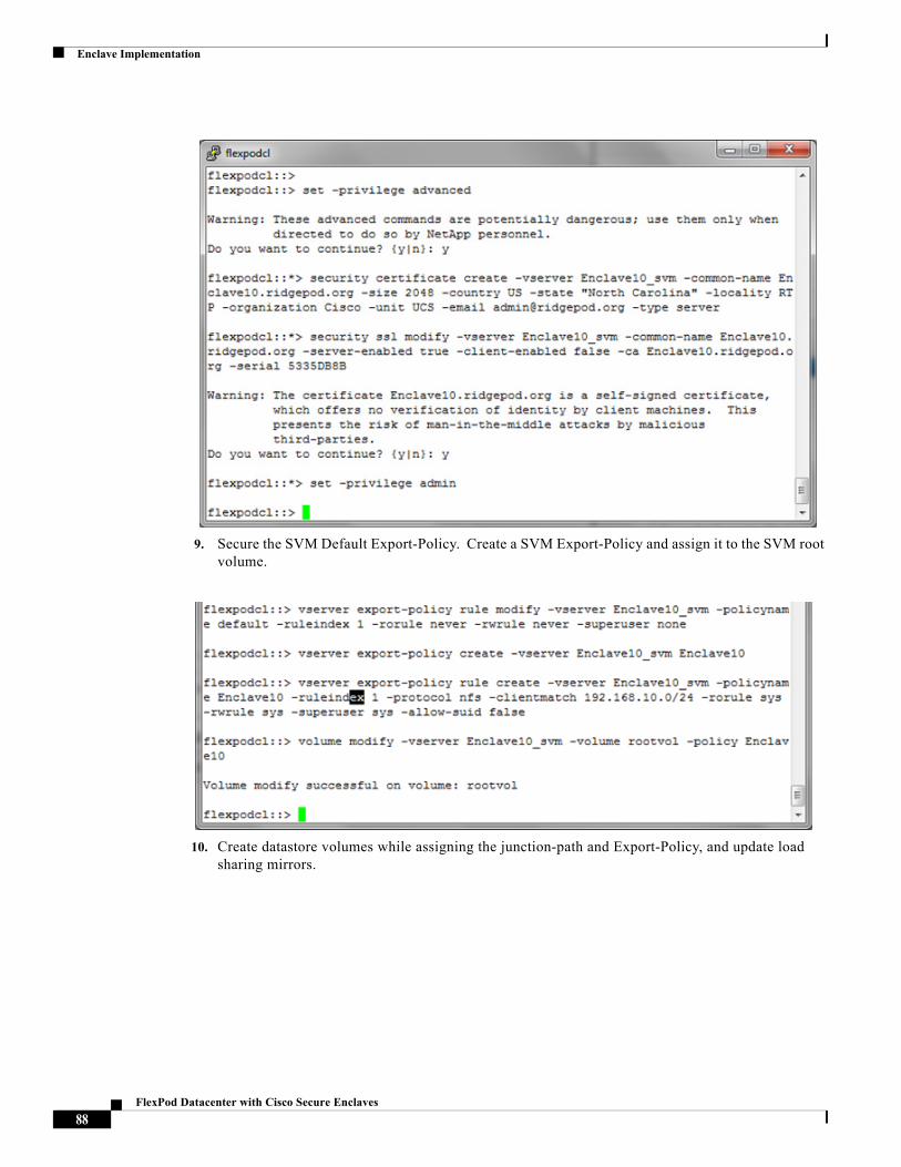
Enclave Implementation
9. Secure the SVM Default Export-Policy. Create a SVM Export-Policy and assign it to the SVM root volume.
10. Create datastore volumes while assigning the junction-path and Export-Policy, and update load sharing mirrors.
88FlexPod Datacenter with Cisco Secure Enclaves
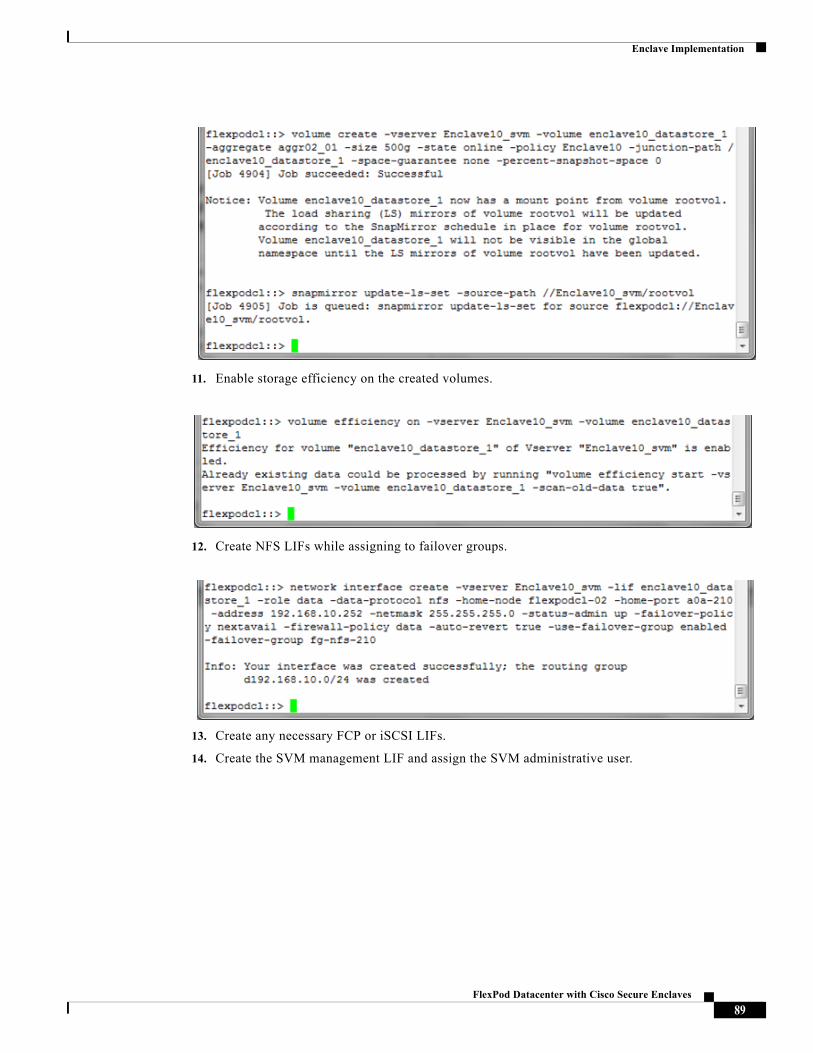
Enclave Implementation
11. Enable storage efficiency on the created volumes.
12. Create NFS LIFs while assigning to failover groups.
13. Create any necessary FCP or iSCSI LIFs.
14. Create the SVM management LIF and assign the SVM administrative user.
89FlexPod Datacenter with Cisco Secure Enclaves
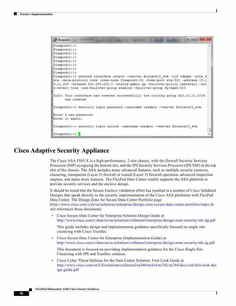
Enclave Implementation
Cisco Adaptive Security Appliance
The Cisco ASA 5585-X is a high-performance, 2-slot chassis, with the firewall Security Services Processor (SSP) occupying the bottom slot, and the IPS Security Services Processor (IPS SSP) in the top slot of the chassis. The ASA includes many advanced features, such as multiple security contexts, clustering, transparent (Layer 2) firewall or routed (Layer 3) firewall operation, advanced inspection engines, and many more features. The FlexPod Data Center readily supports the ASA platform to provide security services and the enclave design.
It should be noted that the Secure Enclave validation effort has resulted in a number of Cisco Validated Designs that speak directly to the security implementation of the Cisco ASA platforms with FlexPod Data Center. The Design Zone for Secure Data Center Portfolio page (http://www.cisco.com/c/en/us/solutions/enterprise/design-zone-secure-data-center-portfolio/index.html) references these documents:
• Cisco Secure Data Center for Enterprise Solution Design Guide at http://www.cisco.com/c/dam/en/us/solutions/collateral/enterprise/design-zone-security/sdc-dg.pdf
This guide includes design and implementation guidance specifically focused on single site clustering with Cisco TrustSec.
• Cisco Secure Data Center for Enterprise (Implementation Guide) at http://www.cisco.com/c/dam/en/us/solutions/collateral/enterprise/design-zone-security/sdc-ig.pdf
This document is focused on providing implementation guidance for the Cisco Single Site Clustering with IPS and TrustSec solution.
• Cisco Cyber Threat Defense for the Data Center Solution: First Look Guide at http://www.cisco.com/en/US/solutions/collateral/ns340/ns414/ns742/ns744/docs/ctd-first-look-design-guide.pdf
90FlexPod Datacenter with Cisco Secure Enclaves
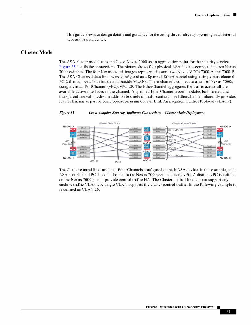
Enclave Implementation
This guide provides design details and guidance for detecting threats already operating in an internal network or data center.
Cluster Mode
The ASA cluster model uses the Cisco Nexus 7000 as an aggregation point for the security service. Figure 35 details the connections. The picture shows four physical ASA devices connected to two Nexus 7000 switches. The four Nexus switch images represent the same two Nexus VDCs 7000-A and 7000-B. The ASA Clustered data links were configured as a Spanned EtherChannel using a single port-channel, PC-2 that supports both inside and outside VLANs. These channels connect to a pair of Nexus 7000s using a virtual PortChannel (vPC), vPC-20. The EtherChannel aggregates the traffic across all the available active interfaces in the channel. A spanned EtherChannel accommodates both routed and transparent firewall modes, in addition to single or multi-context. The EtherChannel inherently provides load balancing as part of basic operation using Cluster Link Aggregation Control Protocol (cLACP).
Figure 35 Cisco Adaptive Security Appliance Connections—Cluster Mode Deployment
The Cluster control links are local EtherChannels configured on each ASA device. In this example, each ASA port channel PC-1 is dual-homed to the Nexus 7000 switches using vPC. A distinct vPC is defined on the Nexus 7000 pair to provide control traffic HA. The Cluster control links do not support any enclave traffic VLANs. A single VLAN supports the cluster control traffic. In the following example it is defined as VLAN 20.
91FlexPod Datacenter with Cisco Secure Enclaves
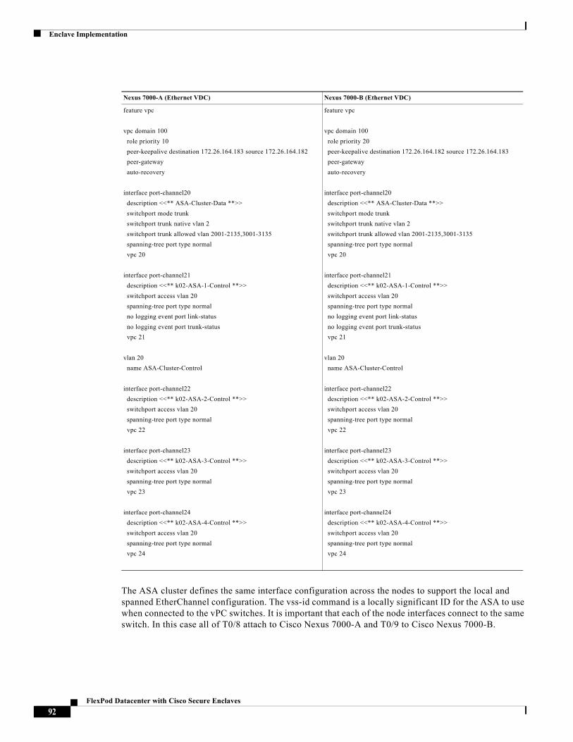
Enclave Implementation
The ASA cluster defines the same interface configuration across the nodes to support the local and spanned EtherChannel configuration. The vss-id command is a locally significant ID for the ASA to use when connected to the vPC switches. It is important that each of the node interfaces connect to the same switch. In this case all of T0/8 attach to Cisco Nexus 7000-A and T0/9 to Cisco Nexus 7000-B.
Nexus 7000-A (Ethernet VDC) Nexus 7000-B (Ethernet VDC)
feature vpc
vpc domain 100
role priority 10
peer-keepalive destination 172.26.164.183 source 172.26.164.182
peer-gateway
auto-recovery
interface port-channel20
description <<** ASA-Cluster-Data **>>
switchport mode trunk
switchport trunk native vlan 2
switchport trunk allowed vlan 2001-2135,3001-3135
spanning-tree port type normal
vpc 20
interface port-channel21
description <<** k02-ASA-1-Control **>>
switchport access vlan 20
spanning-tree port type normal
no logging event port link-status
no logging event port trunk-status
vpc 21
vlan 20
name ASA-Cluster-Control
interface port-channel22
description <<** k02-ASA-2-Control **>>
switchport access vlan 20
spanning-tree port type normal
vpc 22
interface port-channel23
description <<** k02-ASA-3-Control **>>
switchport access vlan 20
spanning-tree port type normal
vpc 23
interface port-channel24
description <<** k02-ASA-4-Control **>>
switchport access vlan 20
spanning-tree port type normal
vpc 24
feature vpc
vpc domain 100
role priority 20
peer-keepalive destination 172.26.164.182 source 172.26.164.183
peer-gateway
auto-recovery
interface port-channel20
description <<** ASA-Cluster-Data **>>
switchport mode trunk
switchport trunk native vlan 2
switchport trunk allowed vlan 2001-2135,3001-3135
spanning-tree port type normal
vpc 20
interface port-channel21
description <<** k02-ASA-1-Control **>>
switchport access vlan 20
spanning-tree port type normal
no logging event port link-status
no logging event port trunk-status
vpc 21
vlan 20
name ASA-Cluster-Control
interface port-channel22
description <<** k02-ASA-2-Control **>>
switchport access vlan 20
spanning-tree port type normal
vpc 22
interface port-channel23
description <<** k02-ASA-3-Control **>>
switchport access vlan 20
spanning-tree port type normal
vpc 23
interface port-channel24
description <<** k02-ASA-4-Control **>>
switchport access vlan 20
spanning-tree port type normal
vpc 24
92FlexPod Datacenter with Cisco Secure Enclaves
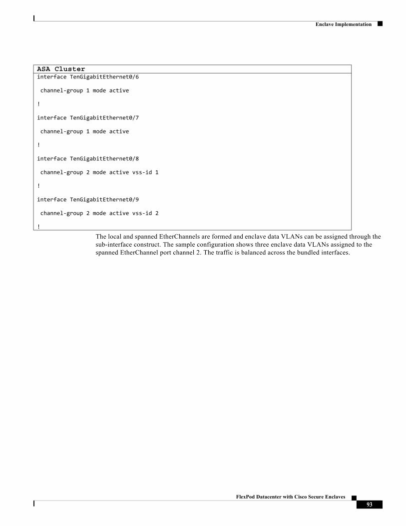
Enclave Implementation
The local and spanned EtherChannels are formed and enclave data VLANs can be assigned through the sub-interface construct. The sample configuration shows three enclave data VLANs assigned to the spanned EtherChannel port channel 2. The traffic is balanced across the bundled interfaces.
ASA Clusterinterface TenGigabitEthernet0/6
channel-group 1 mode active
!
interface TenGigabitEthernet0/7
channel-group 1 mode active
!
interface TenGigabitEthernet0/8
channel-group 2 mode active vss-id 1
!
interface TenGigabitEthernet0/9
channel-group 2 mode active vss-id 2
!
93FlexPod Datacenter with Cisco Secure Enclaves
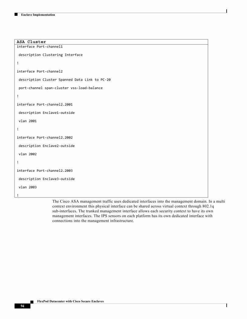
Enclave Implementation
The Cisco ASA management traffic uses dedicated interfaces into the management domain. In a multi context environment this physical interface can be shared across virtual context through 802.1q sub-interfaces. The trunked management interface allows each security context to have its own management interfaces. The IPS sensors on each platform has its own dedicated interface with connections into the management infrastructure.
ASA Clusterinterface Port-channel1
description Clustering Interface
!
interface Port-channel2
description Cluster Spanned Data Link to PC-20
port-channel span-cluster vss-load-balance
!
interface Port-channel2.2001
description Enclave1-outside
vlan 2001
!
interface Port-channel2.2002
description Enclave2-outside
vlan 2002
!
interface Port-channel2.2003
description Enclave3-outside
vlan 2003
!
94FlexPod Datacenter with Cisco Secure Enclaves
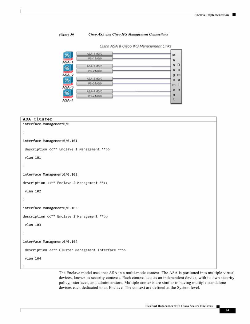
Enclave Implementation
Figure 36 Cisco ASA and Cisco IPS Management Connections
The Enclave model uses that ASA in a multi-mode context. The ASA is portioned into multiple virtual devices, known as security contexts. Each context acts as an independent device, with its own security policy, interfaces, and administrators. Multiple contexts are similar to having multiple standalone devices each dedicated to an Enclave. The context are defined at the System level.
ASA Clusterinterface Management0/0
!
interface Management0/0.101
description <<** Enclave 1 Management **>>
vlan 101
!
interface Management0/0.102
description <<** Enclave 2 Management **>>
vlan 102
!
interface Management0/0.103
description <<** Enclave 3 Management **>>
vlan 103
!
interface Management0/0.164
description <<** Cluster Management Interface **>>
vlan 164
!
95FlexPod Datacenter with Cisco Secure Enclaves
Enclave Implementation
The primary administrative context is the "admin" context. This context is assigned a single management sub-interface for security operations.
Within the admin context a pool of cluster address must be created for distribution to slave nodes as they are added to the ASA cluster. This IP pool construct is repeated for each security context created in ASA cluster. In this example, a pool of four IP address is reserved for the admin context indicating a four node maximum configuration.
The management interface uses the sub-interface assigned in the system context. The cluster IP (172.26.164.191) is assigned and is "owned" only by the master node.
The cluster can now be instantiated in the system context. In this example, the K02-SEA ASA cluster is created on ASA-1. The cluster interface characteristics and associated attributes are defined. This is repeated on each node of the cluster.
ASA Cluster – Admin Context admin-context admin
context admin
allocate-interface Management0/0.164
config-url disk0:/admin.cfg
ASA Cluster – Cluster IP Poolip local pool K02-SEA 172.26.164.157-172.26.164.160 mask 255.255.255.0
ASA Cluster – Cluster IP Poolinterface Management0/0.164
management-only
nameif management
security-level 0
ip address 172.26.164.191 255.255.255.0 cluster-pool K02-SEA
!
96FlexPod Datacenter with Cisco Secure Enclaves
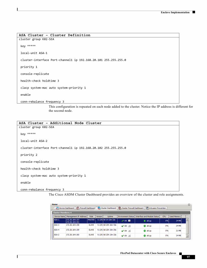
Enclave Implementation
This configuration is repeated on each node added to the cluster. Notice the IP address is different for the second node.
The Cisco ASDM Cluster Dashboard provides an overview of the cluster and role assignments.
ASA Cluster – Cluster Definitioncluster group K02-SEA
key *****
local-unit ASA-1
cluster-interface Port-channel1 ip 192.168.20.101 255.255.255.0
priority 1
console-replicate
health-check holdtime 3
clacp system-mac auto system-priority 1
enable
conn-rebalance frequency 3
ASA Cluster – Additional Node Clustercluster group K02-SEA
key *****
local-unit ASA-2
cluster-interface Port-channel1 ip 192.168.20.102 255.255.255.0
priority 2
console-replicate
health-check holdtime 3
clacp system-mac auto system-priority 1
enable
conn-rebalance frequency 3
97FlexPod Datacenter with Cisco Secure Enclaves
Enclave Implementation
Security Contexts
The security contexts are defined in the system context and allocated network resources. These resources were previously defined as sub-interfaces in the spanned EtherChannel. Names can be attached to the interfaces for use within the security context, in this sample Mgmt, outside and inside are in use.
The Cisco ASDM reflects each security context as an independent firewall. Each of these context is configured and active on each node in the cluster.
ASA Cluster – Enclave Security Contextscontext Enclave1
description Secure Enclave 1
allocate-interface Management0/0.101 Mgmt101
allocate-interface Port-channel2.2001 outside
allocate-interface Port-channel2.3001 inside
config-url disk0:/enclave1.cfg
!
context Enclave2
description Secure Enclave 2
allocate-interface Management0/0.102 Mgmt102
allocate-interface Port-channel2.2002 outside
allocate-interface Port-channel2.3002 inside
config-url disk0:/enclave2.cfg
!
context Enclave3
description Secure Enclave 3
allocate-interface Management0/0.103 mgmt103
allocate-interface Port-channel2.2003 outside
allocate-interface Port-channel2.3003 inside
config-url disk0:/Enclave3.cfg
98FlexPod Datacenter with Cisco Secure Enclaves
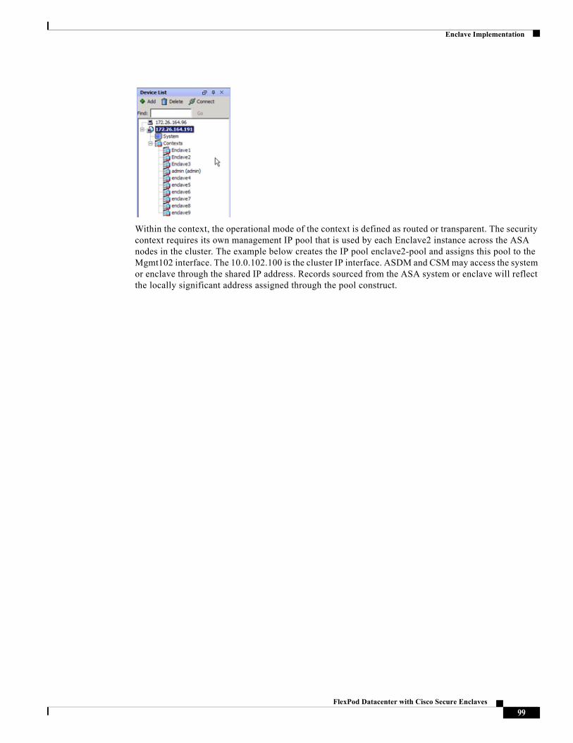
Enclave Implementation
Within the context, the operational mode of the context is defined as routed or transparent. The security context requires its own management IP pool that is used by each Enclave2 instance across the ASA nodes in the cluster. The example below creates the IP pool enclave2-pool and assigns this pool to the Mgmt102 interface. The 10.0.102.100 is the cluster IP interface. ASDM and CSM may access the system or enclave through the shared IP address. Records sourced from the ASA system or enclave will reflect the locally significant address assigned through the pool construct.
99FlexPod Datacenter with Cisco Secure Enclaves
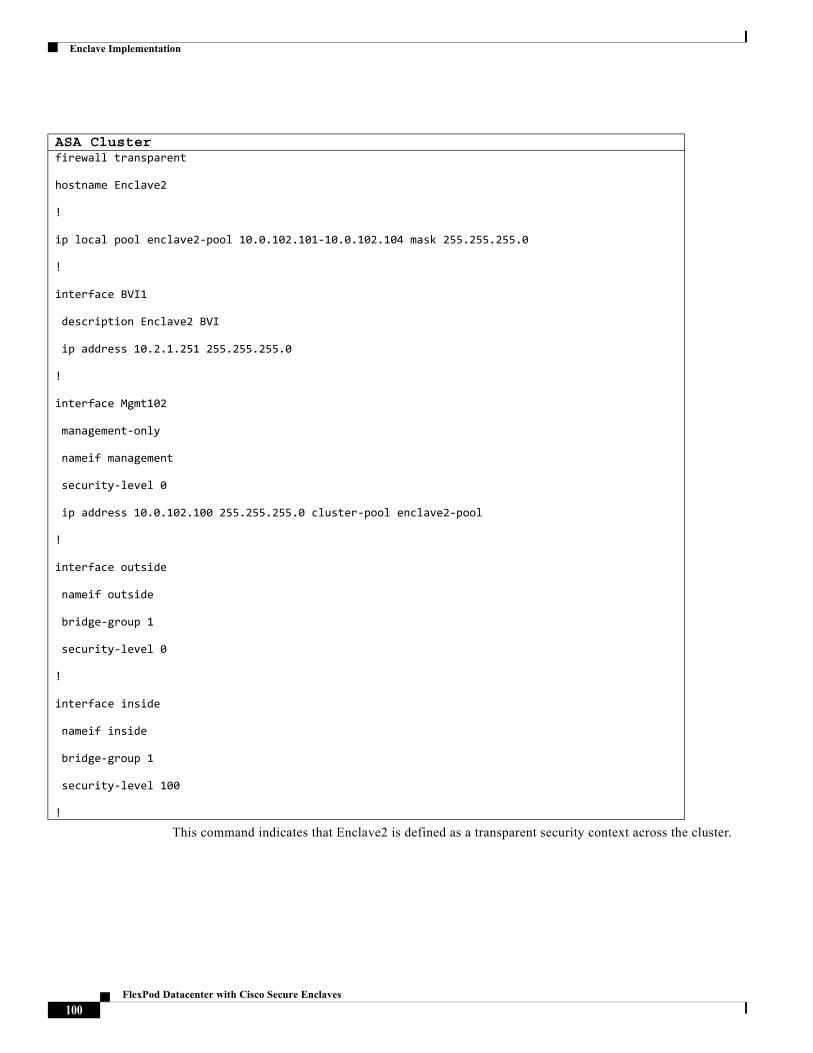
Enclave Implementation
This command indicates that Enclave2 is defined as a transparent security context across the cluster.
ASA Clusterfirewall transparent
hostname Enclave2
!
ip local pool enclave2-pool 10.0.102.101-10.0.102.104 mask 255.255.255.0
!
interface BVI1
description Enclave2 BVI
ip address 10.2.1.251 255.255.255.0
!
interface Mgmt102
management-only
nameif management
security-level 0
ip address 10.0.102.100 255.255.255.0 cluster-pool enclave2-pool
!
interface outside
nameif outside
bridge-group 1
security-level 0
!
interface inside
nameif inside
bridge-group 1
security-level 100
!
100FlexPod Datacenter with Cisco Secure Enclaves
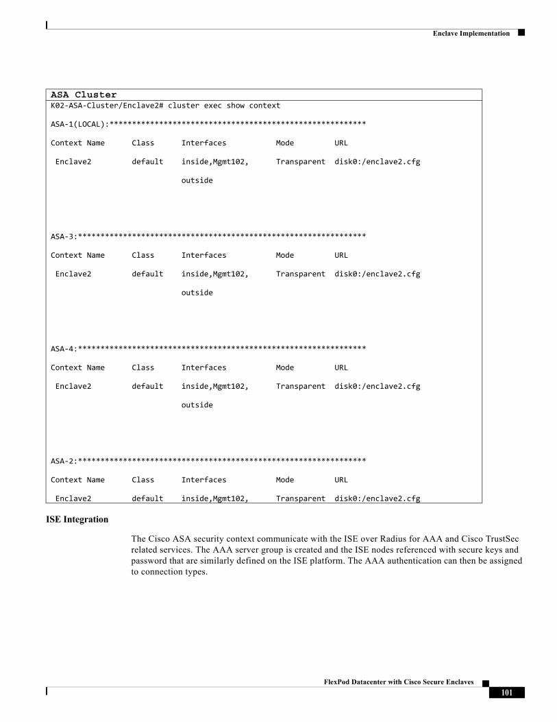
Enclave Implementation
ISE Integration
The Cisco ASA security context communicate with the ISE over Radius for AAA and Cisco TrustSec related services. The AAA server group is created and the ISE nodes referenced with secure keys and password that are similarly defined on the ISE platform. The AAA authentication can then be assigned to connection types.
ASA ClusterK02-ASA-Cluster/Enclave2# cluster exec show context
ASA-1(LOCAL):*********************************************************
Context Name Class Interfaces Mode URL
Enclave2 default inside,Mgmt102, Transparent disk0:/enclave2.cfg
outside
ASA-3:****************************************************************
Context Name Class Interfaces Mode URL
Enclave2 default inside,Mgmt102, Transparent disk0:/enclave2.cfg
outside
ASA-4:****************************************************************
Context Name Class Interfaces Mode URL
Enclave2 default inside,Mgmt102, Transparent disk0:/enclave2.cfg
outside
ASA-2:****************************************************************
Context Name Class Interfaces Mode URL
Enclave2 default inside,Mgmt102, Transparent disk0:/enclave2.cfg
101FlexPod Datacenter with Cisco Secure Enclaves
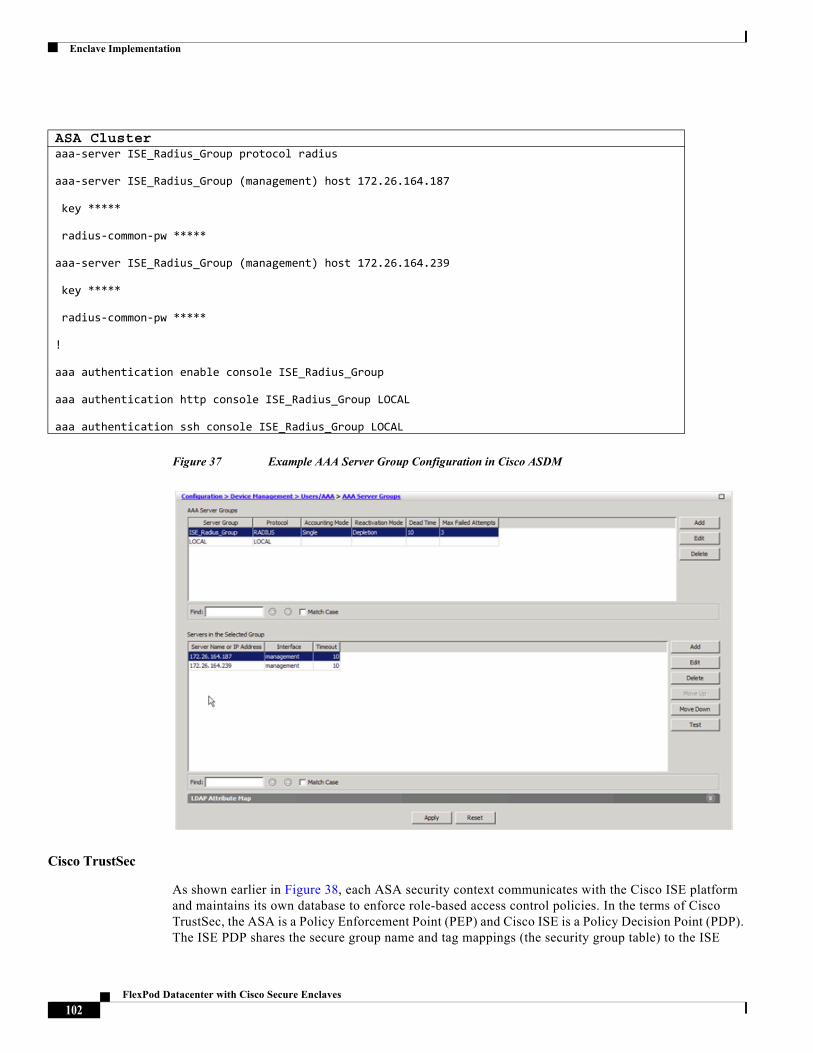
Enclave Implementation
Figure 37 Example AAA Server Group Configuration in Cisco ASDM
Cisco TrustSec
As shown earlier in Figure 38, each ASA security context communicates with the Cisco ISE platform and maintains its own database to enforce role-based access control policies. In the terms of Cisco TrustSec, the ASA is a Policy Enforcement Point (PEP) and Cisco ISE is a Policy Decision Point (PDP). The ISE PDP shares the secure group name and tag mappings (the security group table) to the ISE
ASA Clusteraaa-server ISE_Radius_Group protocol radius
aaa-server ISE_Radius_Group (management) host 172.26.164.187
key *****
radius-common-pw *****
aaa-server ISE_Radius_Group (management) host 172.26.164.239
key *****
radius-common-pw *****
!
aaa authentication enable console ISE_Radius_Group
aaa authentication http console ISE_Radius_Group LOCAL
aaa authentication ssh console ISE_Radius_Group LOCAL
102FlexPod Datacenter with Cisco Secure Enclaves
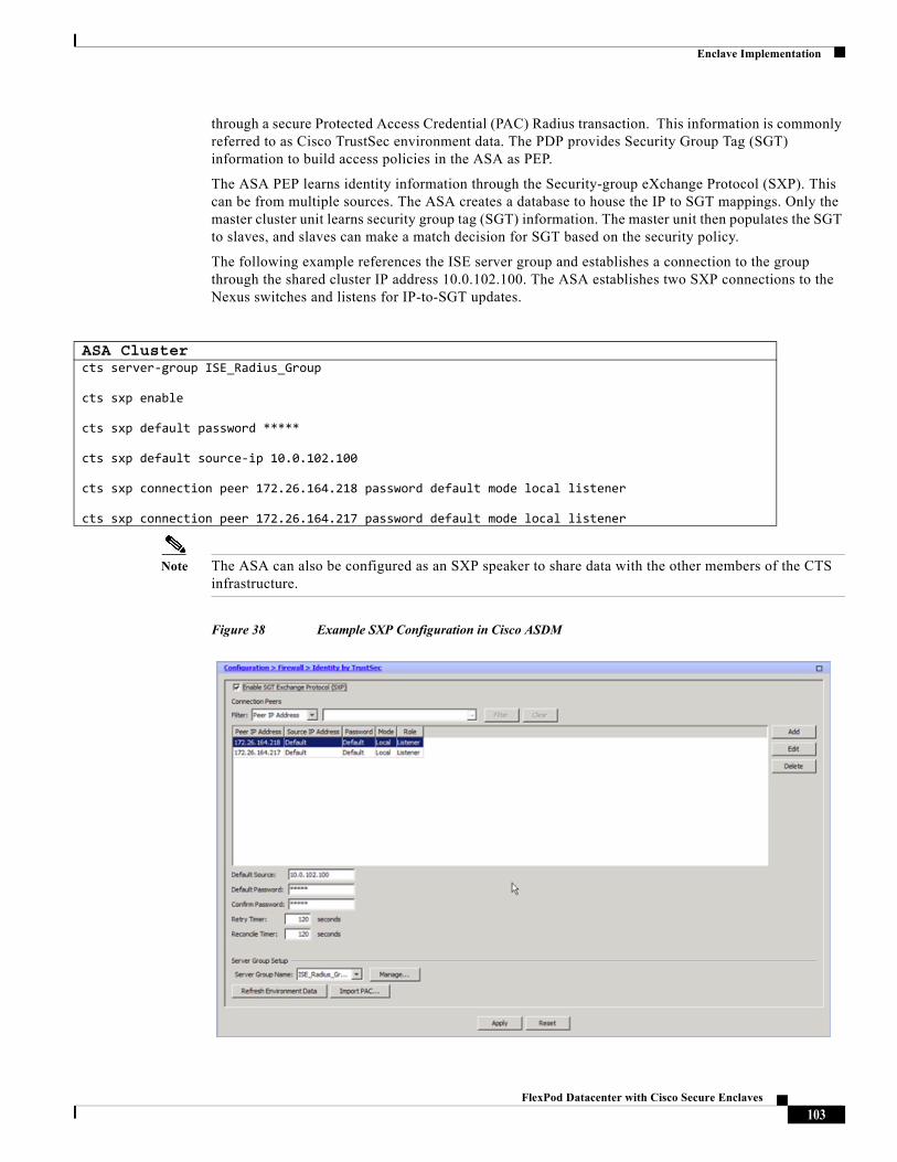
Enclave Implementation
through a secure Protected Access Credential (PAC) Radius transaction. This information is commonly referred to as Cisco TrustSec environment data. The PDP provides Security Group Tag (SGT) information to build access policies in the ASA as PEP.
The ASA PEP learns identity information through the Security-group eXchange Protocol (SXP). This can be from multiple sources. The ASA creates a database to house the IP to SGT mappings. Only the master cluster unit learns security group tag (SGT) information. The master unit then populates the SGT to slaves, and slaves can make a match decision for SGT based on the security policy.
The following example references the ISE server group and establishes a connection to the group through the shared cluster IP address 10.0.102.100. The ASA establishes two SXP connections to the Nexus switches and listens for IP-to-SGT updates.
Note The ASA can also be configured as an SXP speaker to share data with the other members of the CTS infrastructure.
Figure 38 Example SXP Configuration in Cisco ASDM
ASA Clustercts server-group ISE_Radius_Group
cts sxp enable
cts sxp default password *****
cts sxp default source-ip 10.0.102.100
cts sxp connection peer 172.26.164.218 password default mode local listener
cts sxp connection peer 172.26.164.217 password default mode local listener
103FlexPod Datacenter with Cisco Secure Enclaves
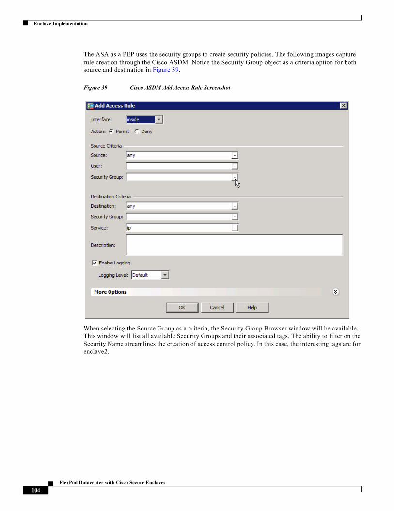
Enclave Implementation
The ASA as a PEP uses the security groups to create security policies. The following images capture rule creation through the Cisco ASDM. Notice the Security Group object as a criteria option for both source and destination in Figure 39.
Figure 39 Cisco ASDM Add Access Rule Screenshot
When selecting the Source Group as a criteria, the Security Group Browser window will be available. This window will list all available Security Groups and their associated tags. The ability to filter on the Security Name streamlines the creation of access control policy. In this case, the interesting tags are for enclave2.
104FlexPod Datacenter with Cisco Secure Enclaves
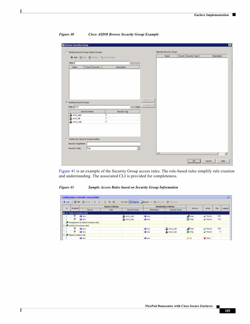
Enclave Implementation
Figure 40 Cisco ASDM Browse Security Group Example
Figure 41 is an example of the Security Group access rules. The role-based rules simplify rule creation and understanding. The associated CLI is provided for completeness.
Figure 41 Sample Access Rules based on Security Group Information
105FlexPod Datacenter with Cisco Secure Enclaves
Enclave Implementation
NetFlow Secure Event Logging (NSEL)
The ASA implements NSEL to provide a stateful, IP flow tracking method that exports only those records that indicate significant events in a flow. In stateful flow tracking, tracked flows go through a series of state changes. NSEL events are used to export data about flow status and are triggered by the event that caused the state change. The significant events that are tracked include flow-create, flow-teardown, and flow-denied. In addition, the ASA generates periodic NSEL events, flow-update events, to provide periodic byte counters over the duration of the flow. These events are usually time-driven, which makes them more in line with traditional NetFlow; however, they may also be triggered by state changes in the flow. In a clustered configuration, each ASA node establishes a connection the flow collector.
Figure 42 is an example of the ASA cluster NSEL configuration through Cisco ASDM. The 172.26.164.240 address is the Lancope Flow Collector. Each node will export data to this collector through its management interface. The command line view is provided for completeness. The global_policy policy map enables NSEL to the flow collector.
Figure 42 Cisco ASDM NetFlow Configuration Example
ASA Cluster – Security Group Access List Exampleaccess-list inside_access_in extended permit icmp security-group name enc2_web any any
access-list inside_access_in extended permit object-group TCPUDP security-group name enc2_web any any eq www
access-list outside_access_in extended permit icmp any security-group name enc2_web any
access-list outside_access_in extended permit object-group TCPUDP any security-group name enc2_web any eq www
106FlexPod Datacenter with Cisco Secure Enclaves
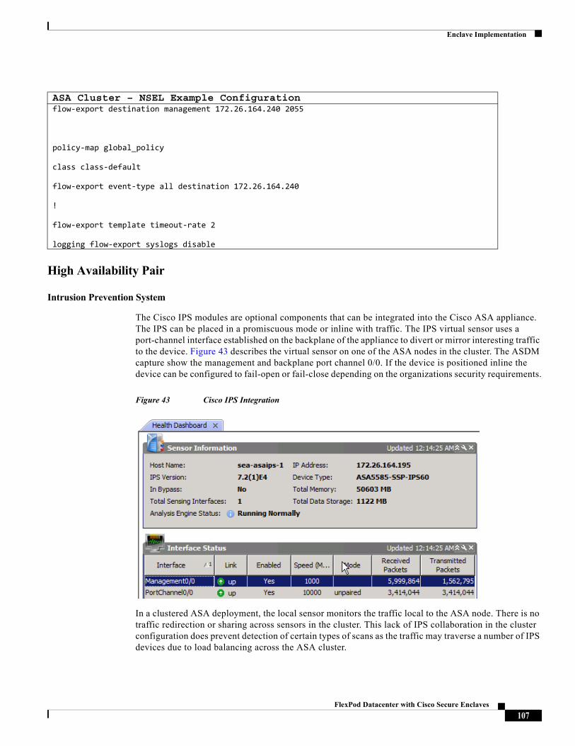
Enclave Implementation
High Availability Pair
Intrusion Prevention System
The Cisco IPS modules are optional components that can be integrated into the Cisco ASA appliance. The IPS can be placed in a promiscuous mode or inline with traffic. The IPS virtual sensor uses a port-channel interface established on the backplane of the appliance to divert or mirror interesting traffic to the device. Figure 43 describes the virtual sensor on one of the ASA nodes in the cluster. The ASDM capture show the management and backplane port channel 0/0. If the device is positioned inline the device can be configured to fail-open or fail-close depending on the organizations security requirements.
Figure 43 Cisco IPS Integration
In a clustered ASA deployment, the local sensor monitors the traffic local to the ASA node. There is no traffic redirection or sharing across sensors in the cluster. This lack of IPS collaboration in the cluster configuration does prevent detection of certain types of scans as the traffic may traverse a number of IPS devices due to load balancing across the ASA cluster.
ASA Cluster – NSEL Example Configurationflow-export destination management 172.26.164.240 2055
policy-map global_policy
class class-default
flow-export event-type all destination 172.26.164.240
!
flow-export template timeout-rate 2
logging flow-export syslogs disable
107FlexPod Datacenter with Cisco Secure Enclaves
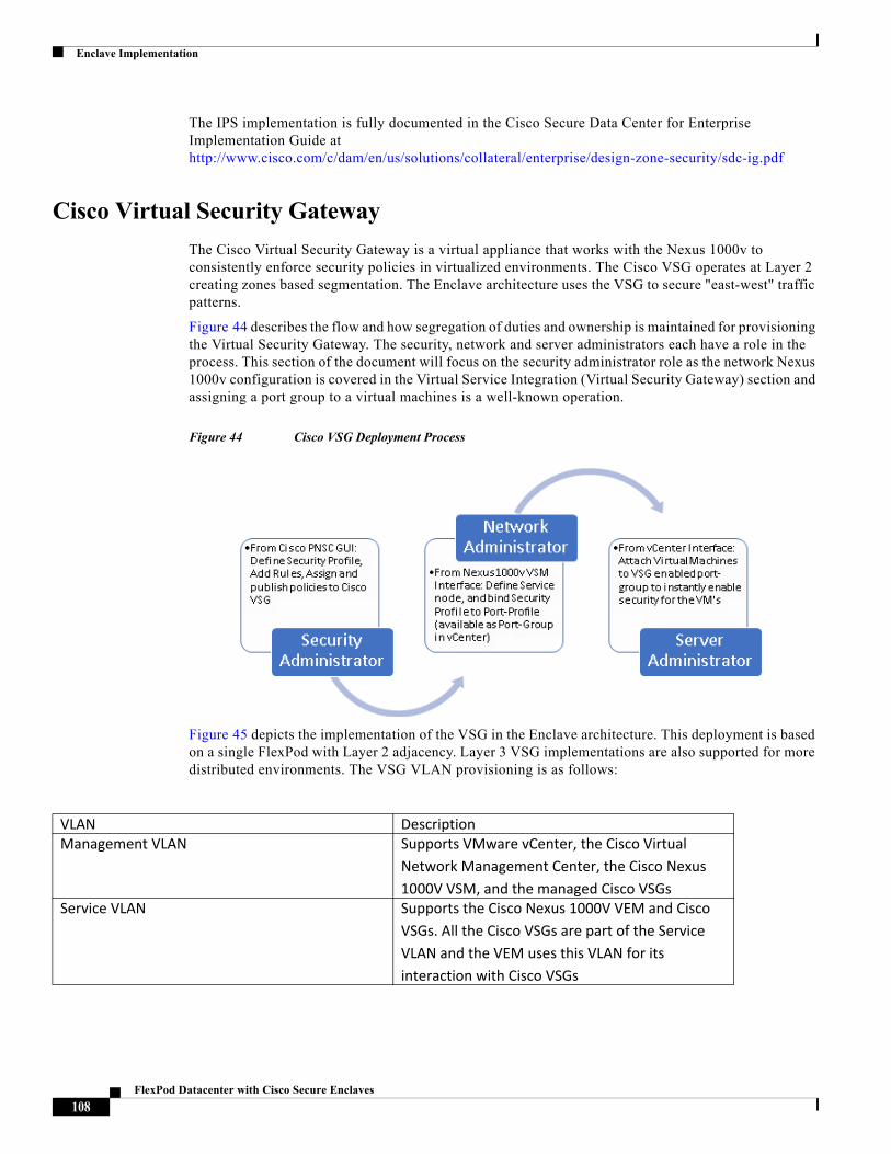
Enclave Implementation
The IPS implementation is fully documented in the Cisco Secure Data Center for Enterprise Implementation Guide at http://www.cisco.com/c/dam/en/us/solutions/collateral/enterprise/design-zone-security/sdc-ig.pdf
Cisco Virtual Security Gateway
The Cisco Virtual Security Gateway is a virtual appliance that works with the Nexus 1000v to consistently enforce security policies in virtualized environments. The Cisco VSG operates at Layer 2 creating zones based segmentation. The Enclave architecture uses the VSG to secure "east-west" traffic patterns.
Figure 44 describes the flow and how segregation of duties and ownership is maintained for provisioning the Virtual Security Gateway. The security, network and server administrators each have a role in the process. This section of the document will focus on the security administrator role as the network Nexus 1000v configuration is covered in the Virtual Service Integration (Virtual Security Gateway) section and assigning a port group to a virtual machines is a well-known operation.
Figure 44 Cisco VSG Deployment Process
Figure 45 depicts the implementation of the VSG in the Enclave architecture. This deployment is based on a single FlexPod with Layer 2 adjacency. Layer 3 VSG implementations are also supported for more distributed environments. The VSG VLAN provisioning is as follows:
VLAN DescriptionManagement VLAN Supports VMware vCenter, the Cisco Virtual
Network Management Center, the Cisco Nexus 1000V VSM, and the managed Cisco VSGs
Service VLAN Supports the Cisco Nexus 1000V VEM and Cisco VSGs. All the Cisco VSGs are part of the Service VLAN and the VEM uses this VLAN for its interaction with Cisco VSGs
108FlexPod Datacenter with Cisco Secure Enclaves
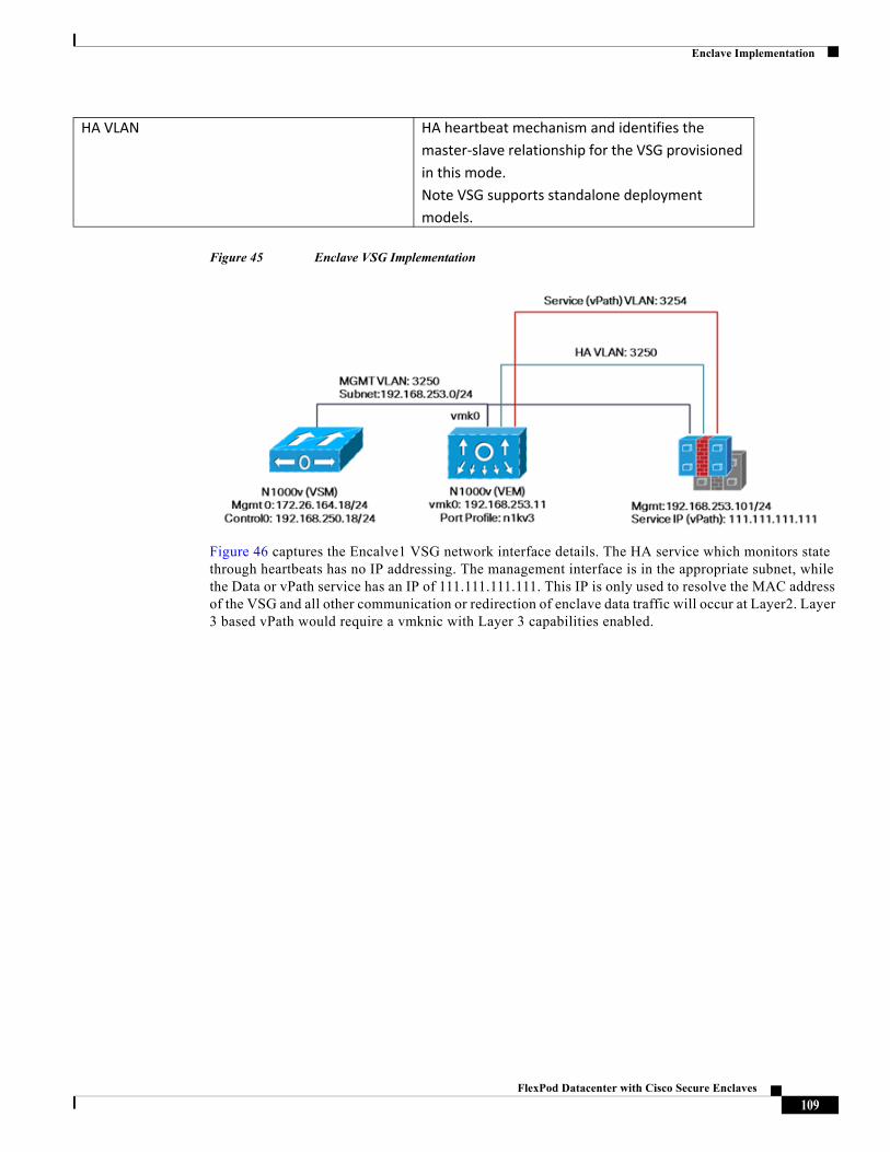
Enclave Implementation
Figure 45 Enclave VSG Implementation
Figure 46 captures the Encalve1 VSG network interface details. The HA service which monitors state through heartbeats has no IP addressing. The management interface is in the appropriate subnet, while the Data or vPath service has an IP of 111.111.111.111. This IP is only used to resolve the MAC address of the VSG and all other communication or redirection of enclave data traffic will occur at Layer2. Layer 3 based vPath would require a vmknic with Layer 3 capabilities enabled.
HA VLAN HA heartbeat mechanism and identifies the master-slave relationship for the VSG provisioned in this mode. Note VSG supports standalone deployment models.
109FlexPod Datacenter with Cisco Secure Enclaves
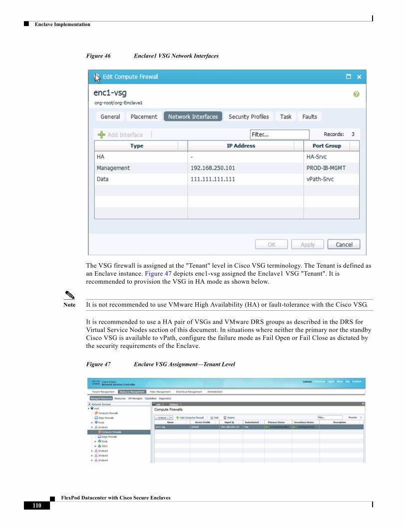
Enclave Implementation
Figure 46 Enclave1 VSG Network Interfaces
The VSG firewall is assigned at the "Tenant" level in Cisco VSG terminology. The Tenant is defined as an Enclave instance. Figure 47 depicts enc1-vsg assigned the Enclave1 VSG "Tenant". It is recommended to provision the VSG in HA mode as shown below.
Note It is not recommended to use VMware High Availability (HA) or fault-tolerance with the Cisco VSG.
It is recommended to use a HA pair of VSGs and VMware DRS groups as described in the DRS for Virtual Service Nodes section of this document. In situations where neither the primary nor the standby Cisco VSG is available to vPath, configure the failure mode as Fail Open or Fail Close as dictated by the security requirements of the Enclave.
Figure 47 Enclave VSG Assignment—Tenant Level
110FlexPod Datacenter with Cisco Secure Enclaves
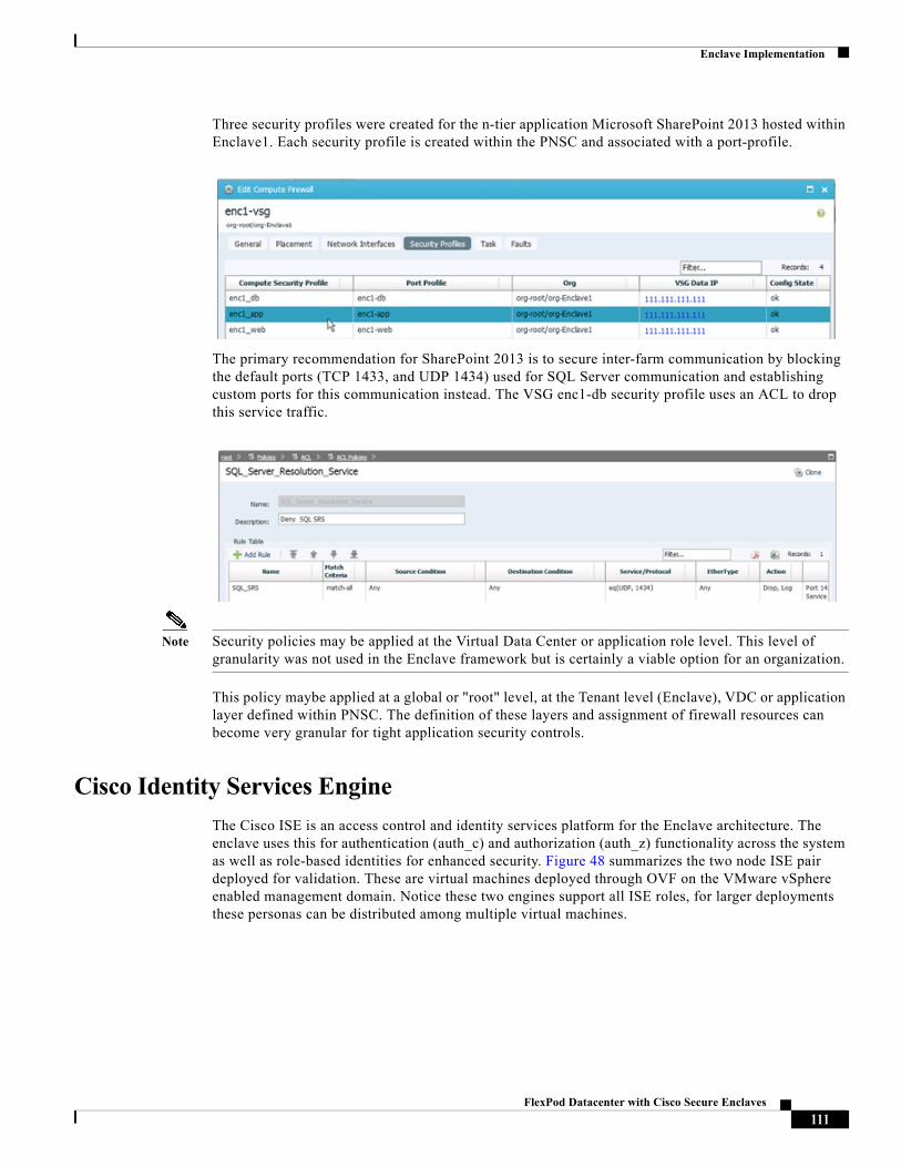
Enclave Implementation
Three security profiles were created for the n-tier application Microsoft SharePoint 2013 hosted within Enclave1. Each security profile is created within the PNSC and associated with a port-profile.
The primary recommendation for SharePoint 2013 is to secure inter-farm communication by blocking the default ports (TCP 1433, and UDP 1434) used for SQL Server communication and establishing custom ports for this communication instead. The VSG enc1-db security profile uses an ACL to drop this service traffic.
Note Security policies may be applied at the Virtual Data Center or application role level. This level of granularity was not used in the Enclave framework but is certainly a viable option for an organization.
This policy maybe applied at a global or "root" level, at the Tenant level (Enclave), VDC or application layer defined within PNSC. The definition of these layers and assignment of firewall resources can become very granular for tight application security controls.
Cisco Identity Services Engine
The Cisco ISE is an access control and identity services platform for the Enclave architecture. The enclave uses this for authentication (auth_c) and authorization (auth_z) functionality across the system as well as role-based identities for enhanced security. Figure 48 summarizes the two node ISE pair deployed for validation. These are virtual machines deployed through OVF on the VMware vSphere enabled management domain. Notice these two engines support all ISE roles, for larger deployments these personas can be distributed among multiple virtual machines.
111FlexPod Datacenter with Cisco Secure Enclaves
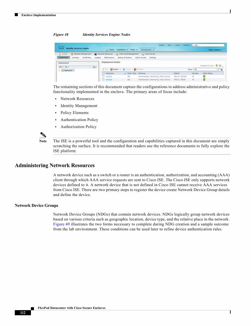
Enclave Implementation
Figure 48 Identity Services Engine Nodes
The remaining sections of this document capture the configurations to address administrative and policy functionality implemented in the enclave. The primary areas of focus include:
• Network Resources
• Identity Management
• Policy Elements
• Authentication Policy
• Authorization Policy
Note The ISE is a powerful tool and the configuration and capabilities captured in this document are simply scratching the surface. It is recommended that readers use the reference documents to fully explore the ISE platform.
Administering Network Resources
A network device such as a switch or a router is an authentication, authorization, and accounting (AAA) client through which AAA service requests are sent to Cisco ISE. The Cisco ISE only supports network devices defined to it. A network device that is not defined in Cisco ISE cannot receive AAA services from Cisco ISE. There are two primary steps to register the device create Network Device Group details and define the device.
Network Device Groups
Network Device Groups (NDGs) that contain network devices. NDGs logically group network devices based on various criteria such as geographic location, device type, and the relative place in the network. Figure 49 illustrates the two forms necessary to complete during NDG creation and a sample outcome from the lab environment. These conditions can be used later to refine device authentication rules.
112FlexPod Datacenter with Cisco Secure Enclaves
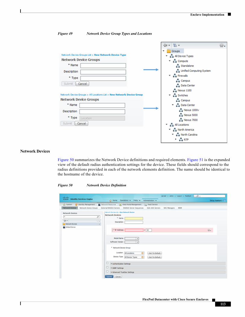
Enclave Implementation
Figure 49 Network Device Group Types and Locations
Network Devices
Figure 50 summarizes the Network Device definitions and required elements. Figure 51 is the expanded view of the default radius authentication settings for the device. These fields should correspond to the radius definitions provided in each of the network elements definition. The name should be identical to the hostname of the device.
Figure 50 Network Device Definition
113FlexPod Datacenter with Cisco Secure Enclaves
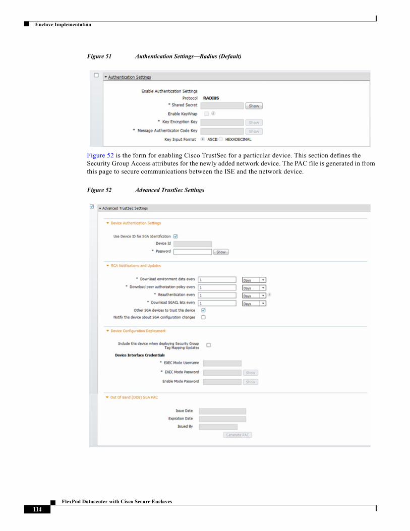
Enclave Implementation
Figure 51 Authentication Settings—Radius (Default)
Figure 52 is the form for enabling Cisco TrustSec for a particular device. This section defines the Security Group Access attributes for the newly added network device. The PAC file is generated in from this page to secure communications between the ISE and the network device.
Figure 52 Advanced TrustSec Settings
114FlexPod Datacenter with Cisco Secure Enclaves
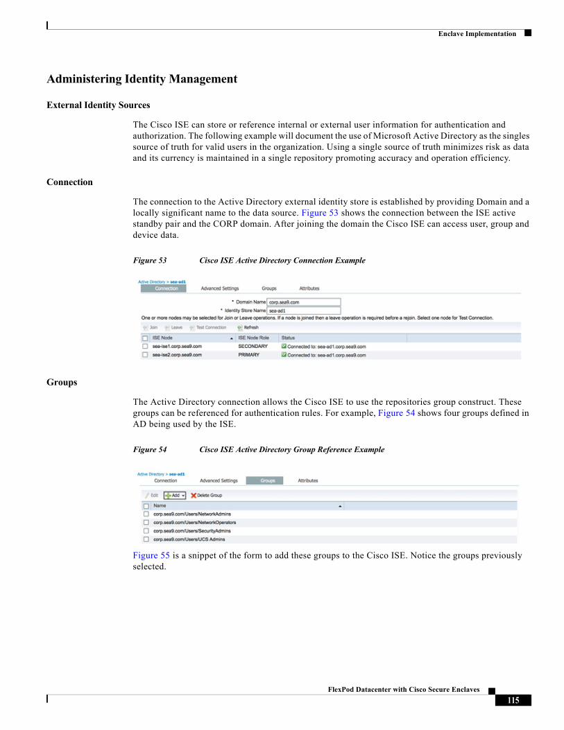
Enclave Implementation
Administering Identity Management
External Identity Sources
The Cisco ISE can store or reference internal or external user information for authentication and authorization. The following example will document the use of Microsoft Active Directory as the singles source of truth for valid users in the organization. Using a single source of truth minimizes risk as data and its currency is maintained in a single repository promoting accuracy and operation efficiency.
Connection
The connection to the Active Directory external identity store is established by providing Domain and a locally significant name to the data source. Figure 53 shows the connection between the ISE active standby pair and the CORP domain. After joining the domain the Cisco ISE can access user, group and device data.
Figure 53 Cisco ISE Active Directory Connection Example
Groups
The Active Directory connection allows the Cisco ISE to use the repositories group construct. These groups can be referenced for authentication rules. For example, Figure 54 shows four groups defined in AD being used by the ISE.
Figure 54 Cisco ISE Active Directory Group Reference Example
Figure 55 is a snippet of the form to add these groups to the Cisco ISE. Notice the groups previously selected.
115FlexPod Datacenter with Cisco Secure Enclaves
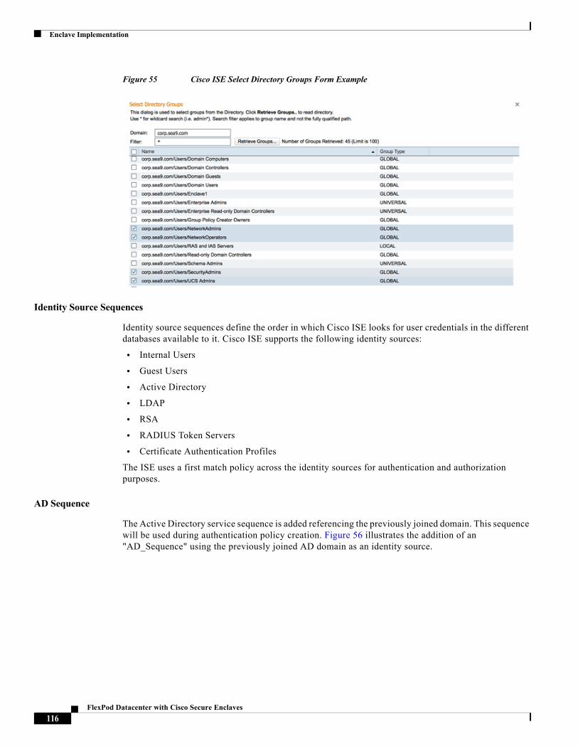
Enclave Implementation
Figure 55 Cisco ISE Select Directory Groups Form Example
Identity Source Sequences
Identity source sequences define the order in which Cisco ISE looks for user credentials in the different databases available to it. Cisco ISE supports the following identity sources:
• Internal Users
• Guest Users
• Active Directory
• LDAP
• RSA
• RADIUS Token Servers
• Certificate Authentication Profiles
The ISE uses a first match policy across the identity sources for authentication and authorization purposes.
AD Sequence
The Active Directory service sequence is added referencing the previously joined domain. This sequence will be used during authentication policy creation. Figure 56 illustrates the addition of an "AD_Sequence" using the previously joined AD domain as an identity source.
116FlexPod Datacenter with Cisco Secure Enclaves
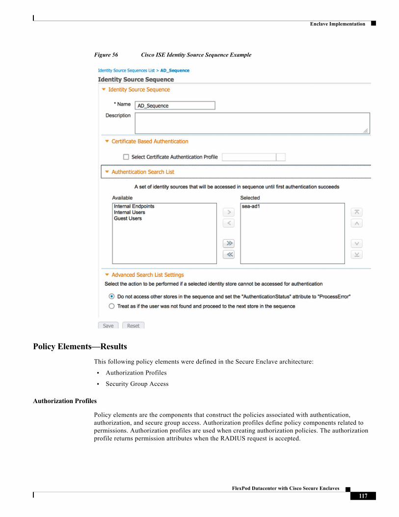
Enclave Implementation
Figure 56 Cisco ISE Identity Source Sequence Example
Policy Elements—Results
This following policy elements were defined in the Secure Enclave architecture:
• Authorization Profiles
• Security Group Access
Authorization Profiles
Policy elements are the components that construct the policies associated with authentication, authorization, and secure group access. Authorization profiles define policy components related to permissions. Authorization profiles are used when creating authorization policies. The authorization profile returns permission attributes when the RADIUS request is accepted.
117FlexPod Datacenter with Cisco Secure Enclaves
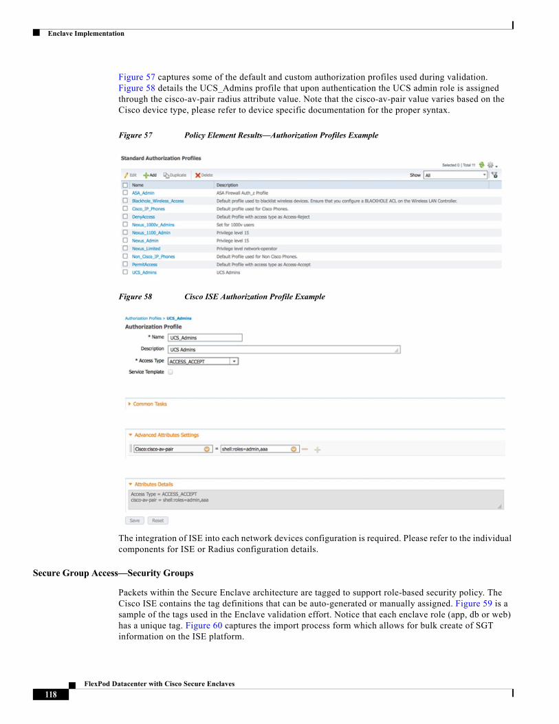
Enclave Implementation
Figure 57 captures some of the default and custom authorization profiles used during validation. Figure 58 details the UCS_Admins profile that upon authentication the UCS admin role is assigned through the cisco-av-pair radius attribute value. Note that the cisco-av-pair value varies based on the Cisco device type, please refer to device specific documentation for the proper syntax.
Figure 57 Policy Element Results—Authorization Profiles Example
Figure 58 Cisco ISE Authorization Profile Example
The integration of ISE into each network devices configuration is required. Please refer to the individual components for ISE or Radius configuration details.
Secure Group Access—Security Groups
Packets within the Secure Enclave architecture are tagged to support role-based security policy. The Cisco ISE contains the tag definitions that can be auto-generated or manually assigned. Figure 59 is a sample of the tags used in the Enclave validation effort. Notice that each enclave role (app, db or web) has a unique tag. Figure 60 captures the import process form which allows for bulk create of SGT information on the ISE platform.
118FlexPod Datacenter with Cisco Secure Enclaves
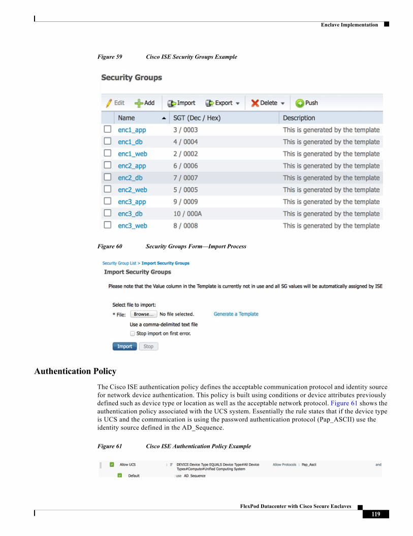
Enclave Implementation
Figure 59 Cisco ISE Security Groups Example
Figure 60 Security Groups Form—Import Process
Authentication Policy
The Cisco ISE authentication policy defines the acceptable communication protocol and identity source for network device authentication. This policy is built using conditions or device attributes previously defined such as device type or location as well as the acceptable network protocol. Figure 61 shows the authentication policy associated with the UCS system. Essentially the rule states that if the device type is UCS and the communication is using the password authentication protocol (Pap_ASCII) use the identity source defined in the AD_Sequence.
Figure 61 Cisco ISE Authentication Policy Example
119FlexPod Datacenter with Cisco Secure Enclaves
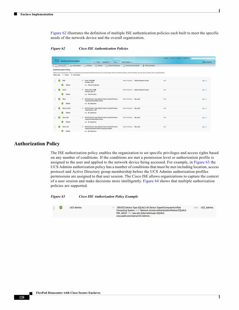
Enclave Implementation
Figure 62 illustrates the definition of multiple ISE authentication policies each built to meet the specific needs of the network device and the overall organization.
Figure 62 Cisco ISE Authentication Policies
Authorization Policy
The ISE authorization policy enables the organization to set specific privileges and access rights based on any number of conditions. If the conditions are met a permission level or authorization profile is assigned to the user and applied to the network device being accessed. For example, in Figure 63 the UCS Admins authorization policy has a number of conditions that must be met including location, access protocol and Active Directory group membership before the UCS Admins authorization profiles permissions are assigned to that user session. The Cisco ISE allows organizations to capture the context of a user session and make decisions more intelligently. Figure 64 shows that multiple authorization policies are supported.
Figure 63 Cisco ISE Authorization Policy Example
120FlexPod Datacenter with Cisco Secure Enclaves
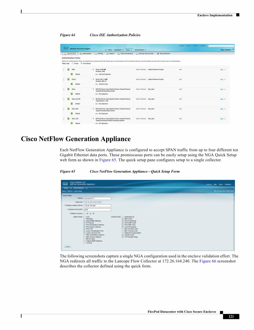
Enclave Implementation
Figure 64 Cisco ISE Authorization Policies
Cisco NetFlow Generation Appliance
Each NetFlow Generation Appliance is configured to accept SPAN traffic from up to four different ten Gigabit Ethernet data ports. These promiscuous ports can be easily setup using the NGA Quick Setup web form as shown in Figure 65. The quick setup pane configures setup to a single collector.
Figure 65 Cisco NetFlow Generation Appliance—Quick Setup Form
The following screenshots capture a single NGA configuration used in the enclave validation effort. The NGA redirects all traffic to the Lancope Flow Collector at 172.26.164.240. The Figure 66 screenshot describes the collector defined using the quick form.
121FlexPod Datacenter with Cisco Secure Enclaves
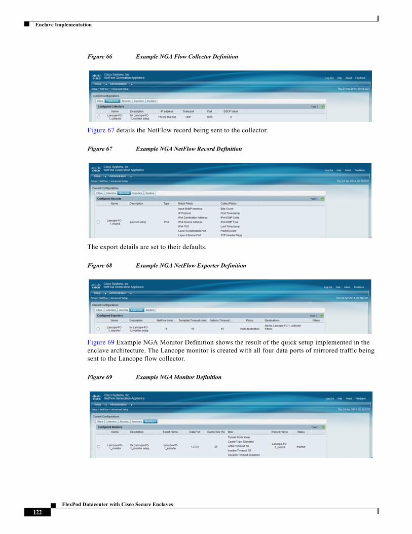
Enclave Implementation
Figure 66 Example NGA Flow Collector Definition
Figure 67 details the NetFlow record being sent to the collector.
Figure 67 Example NGA NetFlow Record Definition
The export details are set to their defaults.
Figure 68 Example NGA NetFlow Exporter Definition
Figure 69 Example NGA Monitor Definition shows the result of the quick setup implemented in the enclave architecture. The Lancope monitor is created with all four data ports of mirrored traffic being sent to the Lancope flow collector.
Figure 69 Example NGA Monitor Definition
122FlexPod Datacenter with Cisco Secure Enclaves
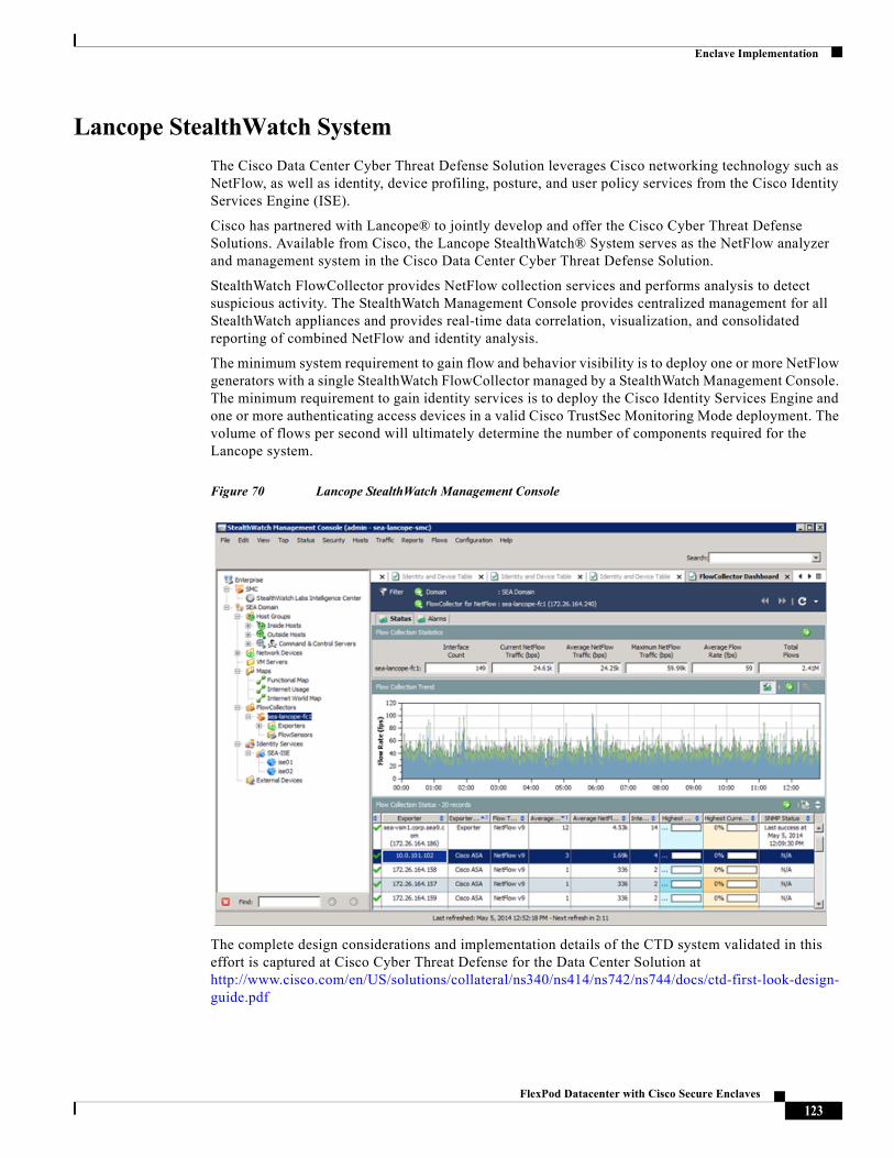
Enclave Implementation
Lancope StealthWatch System
The Cisco Data Center Cyber Threat Defense Solution leverages Cisco networking technology such as NetFlow, as well as identity, device profiling, posture, and user policy services from the Cisco Identity Services Engine (ISE).
Cisco has partnered with Lancope® to jointly develop and offer the Cisco Cyber Threat Defense Solutions. Available from Cisco, the Lancope StealthWatch® System serves as the NetFlow analyzer and management system in the Cisco Data Center Cyber Threat Defense Solution.
StealthWatch FlowCollector provides NetFlow collection services and performs analysis to detect suspicious activity. The StealthWatch Management Console provides centralized management for all StealthWatch appliances and provides real-time data correlation, visualization, and consolidated reporting of combined NetFlow and identity analysis.
The minimum system requirement to gain flow and behavior visibility is to deploy one or more NetFlow generators with a single StealthWatch FlowCollector managed by a StealthWatch Management Console. The minimum requirement to gain identity services is to deploy the Cisco Identity Services Engine and one or more authenticating access devices in a valid Cisco TrustSec Monitoring Mode deployment. The volume of flows per second will ultimately determine the number of components required for the Lancope system.
Figure 70 Lancope StealthWatch Management Console
The complete design considerations and implementation details of the CTD system validated in this effort is captured at Cisco Cyber Threat Defense for the Data Center Solution at http://www.cisco.com/en/US/solutions/collateral/ns340/ns414/ns742/ns744/docs/ctd-first-look-design-guide.pdf
123FlexPod Datacenter with Cisco Secure Enclaves
Conclusion
ConclusionThere are many challenges facing organizations today including changing business models where workloads are moving to the clouds and users demand ubiquitous access with any device. This new reality places pressure on organizations to address a larger dynamic threat landscape with consistent security policy and enforcement where the perimeter of the network is no longer clearly defined. The edge of the data center has become vague.
The Secure Enclave architecture proposes a standard approach to application security. The Secure Enclave extends the FlexPod Data Center infrastructure by integrating and enabling security technologies uniformly, allowing application specific policies to be consistently enforced. The standardization on the Enclave model facilitates operational efficiencies through automation. The Secure Enclave Architecture allows the enterprise to consume the FlexPod infrastructure securely and address the complete attack continuum, user to application.
ReferencesCisco Secure Enclaves Architecture Design Guide http://www.cisco.com/c/en/us/products/collateral/servers-unified-computing/ucs-manager/whitepaper-c07-731204.html
Cisco Secure Data Center for Enterprise Solution Design Guide at http://www.cisco.com/c/dam/en/us/solutions/collateral/enterprise/design-zone-security/sdc-dg.pdf
Cisco Secure Data Center for Enterprise (Implementation Guide) at http://www.cisco.com/c/dam/en/us/solutions/collateral/enterprise/design-zone-security/sdc-ig.pdf
Cisco Cyber Threat Defense for the Data Center Solution: First Look Guide at http://www.cisco.com/en/US/solutions/collateral/ns340/ns414/ns742/ns744/docs/ctd-first-look-design-guide.pdf
124FlexPod Datacenter with Cisco Secure Enclaves