Embed Size (px)
Citation preview
Installation Instructions
FLEX I/O EtherNet/IP Adapter Module
Catalog Numbers 1794-AENT
Use this manual as a guide to install the FLEX I/O EtherNet/IP Adapter Module. Note that this manual covers hardware installation only. Refer to the FLEX I/O EtherNet/IP Adapter Module User Manual, publication number 1794-UM006, for information on configuring the module for use on your network.
The following table lists the contents of this manual and where to find specific information.
Topic See Page
Important User Information 2
European Communities (EC) Directive Compliance 4
EMC Directive 4
Low Voltage Directive 4
Environment and Enclosure 5
Identify Module Components 6
Mounting the Adapter on a DIN Rail Before Installing Modules 7
Mounting (or Replacing) the Adapter on an Existing System 8
Wiring 10
LED Status Indicators 12
Hazardous Location Approval 14
Specifications 15
Mounting Dimensions 16
Ethernet is a trademark of Digital Equipment Corporation, Intel, and Xerox Corporation.FLEX I/O is a trademark of Rockwell Automation
Publication 1794-IN082A-EN-P - June 2001
2 FLEX I/O EtherNet/IP Adapter Module
Important User InformationBecause of the variety of uses for the products described in this publication, those responsible for the application and use of this control equipment must satisfy themselves that all necessary steps have been taken to assure that each application and use meets all performance and safety requirements, including any applicable laws, regulations, codes and standards.
The illustrations, charts, sample programs and layout examples shown in this guide are intended solely for purposes of example. Since there are many variables and requirements associated with any particular installation, Allen-Bradley does not assume responsibility or liability (to include intellectual property liability) for actual use based upon the examples shown in this publication.
Allen-Bradley publication SGI-1.1, Safety Guidelines for the Application, Installation and Maintenance of Solid-State Control (available from your local Allen-Bradley office), describes some important differences between solid-state equipment and electromechanical devices that should be taken into consideration when applying products such as those described in this publication.
Reproduction of the contents of this copyrighted publication, in whole or part, without written permission of Rockwell Automation, is prohibited.
Publication 1794-IN082A-EN-P - June 2001
FLEX I/O EtherNet/IP Adapter Module 3
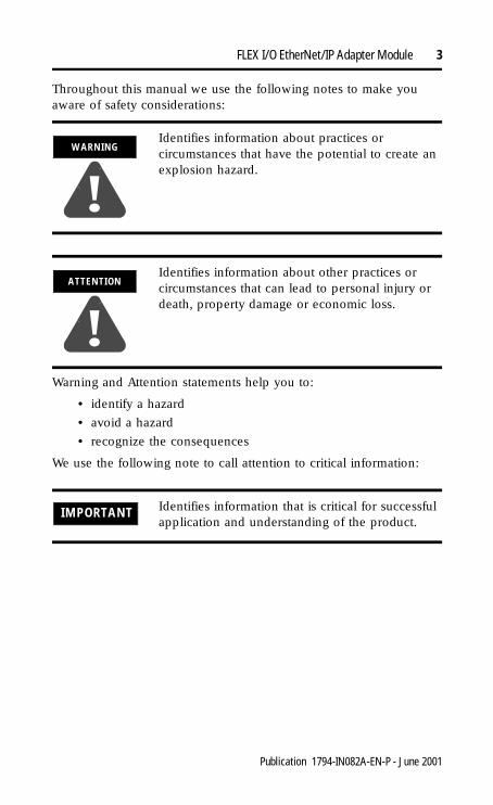
Throughout this manual we use the following notes to make you aware of safety considerations:
Warning and Attention statements help you to:
• identify a hazard
• avoid a hazard
• recognize the consequences
We use the following note to call attention to critical information:
WARNING
!Identifies information about practices or circumstances that have the potential to create an explosion hazard.
ATTENTION
!Identifies information about other practices or circumstances that can lead to personal injury or death, property damage or economic loss.
IMPORTANT Identifies information that is critical for successful application and understanding of the product.
Publication 1794-IN082A-EN-P - June 2001
4 FLEX I/O EtherNet/IP Adapter Module
European Communities (EC) Directive ComplianceIf this product has the CE mark it is approved for installation within the European Union and EEA regions. It has been designed and tested to meet the following directives.
EMC Directive
This product is tested to meet the Council Directive 89/336/EC Electromagnetic Compatibility (EMC) by applying the following standards, in whole or in part, documented in a technical construction file:
• EN 50081-2 EMC — Generic Emission Standard, Part 2 — Industrial Environment
• EN 50082-2 EMC — Generic Immunity Standard, Part 2 — Industrial Environment
This product is intended for use in an industrial environment.
Low Voltage Directive
This product is tested to meet Council Directive 73/23/EEC Low Voltage, by applying the safety requirements of EN 61131-2 Programmable Controllers, Part 2 - Equipment Requirements and Tests. For specific information required by EN 61131-2, see the appropriate sections in this publication, as well as Allen-Bradley publication 1770-4.1, Industrial Automation Wiring and Grounding Guidelines.
Publication 1794-IN082A-EN-P - June 2001
FLEX I/O EtherNet/IP Adapter Module 5
Environment and EnclosureThis equipment is intended to operate in a Pollution Degree 2 industrial control environment, in overvoltage category II applications, (as defined in IEC publication 60664-1) at altitudes up to 2000 meters without derating.
It must be mounted within a system enclosure, suitably designed for those specific environmental conditions that will be present, and appropriately designed to prevent personal injury resulting from accessibility to live parts. The interior of this enclosure must be accessible only by the use of a tool.
Note: See NEMA Standards publication 250 and IEC publication 60529, as applicable, for explanations of the degrees of protection provided by different types of enclosure.
Publication 1794-IN082A-EN-P - June 2001
6 FLEX I/O EtherNet/IP Adapter Module
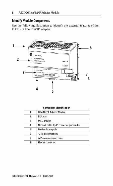
Identify Module ComponentsUse the following illustration to identify the external features of the FLEX I/O EtherNet/IP adapter.
Component Identification
1 EtherNet/IP Adapter Module
2 Indicators
3 MAC ID Label
4 Network cable RJ-45 connector (underside)
5 Module locking tab
6 +24V dc connections
7 24V common connections
8 Flexbus connector
1
2
3
6
4 5
7
8
Publication 1794-IN082A-EN-P - June 2001
FLEX I/O EtherNet/IP Adapter Module 7
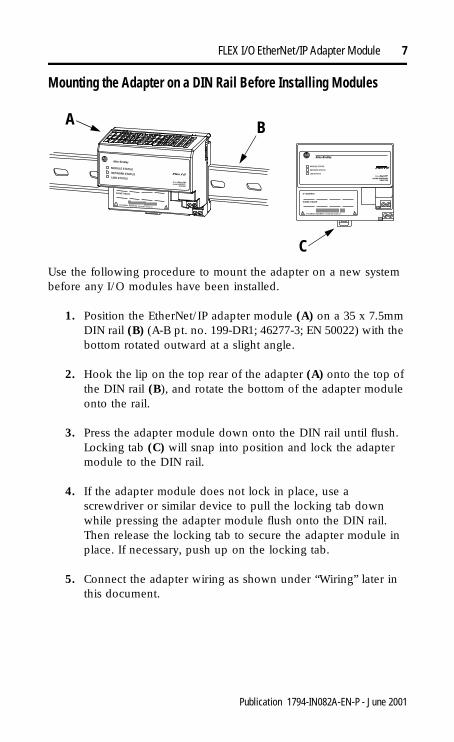
Mounting the Adapter on a DIN Rail Before Installing Modules
Use the following procedure to mount the adapter on a new system before any I/O modules have been installed.
1. Position the EtherNet/IP adapter module (A) on a 35 x 7.5mm DIN rail (B) (A-B pt. no. 199-DR1; 46277-3; EN 50022) with the bottom rotated outward at a slight angle.
2. Hook the lip on the top rear of the adapter (A) onto the top of the DIN rail (B), and rotate the bottom of the adapter module onto the rail.
3. Press the adapter module down onto the DIN rail until flush. Locking tab (C) will snap into position and lock the adapter module to the DIN rail.
4. If the adapter module does not lock in place, use a screwdriver or similar device to pull the locking tab down while pressing the adapter module flush onto the DIN rail. Then release the locking tab to secure the adapter module in place. If necessary, push up on the locking tab.
5. Connect the adapter wiring as shown under “Wiring” later in this document.
A B
C
Publication 1794-IN082A-EN-P - June 2001
8 FLEX I/O EtherNet/IP Adapter Module
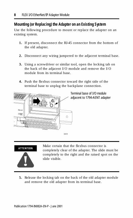
Mounting (or Replacing) the Adapter on an Existing SystemUse the following procedure to mount or replace the adapter on an existing system.
1. If present, disconnect the RJ-45 connector from the bottom of the old adapter.
2. Disconnect any wiring jumpered to the adjacent terminal base.
3. Using a screwdriver or similar tool, open the locking tab on the back of the adjacent I/O module and remove the I/O module from its terminal base.
4. Push the flexbus connector toward the right side of the terminal base to unplug the backplane connection.
5. Release the locking tab on the back of the old adapter module and remove the old adapter from its terminal base.
ATTENTION
!Make certain that the flexbus connector is completely clear of the adapter. The slide must be completely to the right and the raised spot on the slide visible.
31244-M
Terminal base of I/O moduleadjacent to 1794-AENT adapter
Publication 1794-IN082A-EN-P - June 2001
FLEX I/O EtherNet/IP Adapter Module 9
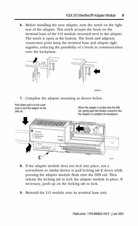
6. Before installing the new adapter, note the notch on the right rear of the adapter. This notch accepts the hook on the terminal base of the I/O module mounted next to the adapter. The notch is open at the bottom. The hook and adjacent connection point keep the terminal base and adapter tight together, reducing the possibility of a break in communication over the backplane.
7. Complete the adapter mounting as shown below.
8. If the adapter module does not lock into place, use a screwdriver or similar device to pull locking tab C down while pressing the adapter module flush onto the DIN rail. Then release the locking tab to lock the adapter module in place. If necessary, push up on the locking tab to lock.
9. Reinstall the I/O module onto its terminal base unit.
31245-M
31244-M
Push down and in at the same time to lock the adapter on the DIN rail.
When the adapter is locked onto the DIN rail, gently push the flexbus connector into the adapter to complete the backplane.
C
Publication 1794-IN082A-EN-P - June 2001
10 FLEX I/O EtherNet/IP Adapter Module
Wiring
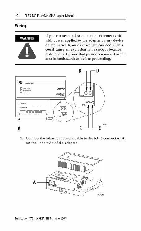
1. Connect the Ethernet network cable to the RJ-45 connector (A) on the underside of the adapter.
WARNING
!If you connect or disconnect the Ethernet cable with power applied to the adapter or any device on the network, an electrical arc can occur. This could cause an explosion in hazardous location installations. Be sure that power is removed or the area is nonhazardous before proceeding.
31246-M
A C E
B D
31247-M
A
Publication 1794-IN082A-EN-P - June 2001
FLEX I/O EtherNet/IP Adapter Module 11
2. Connect 24V common to the left side of the upper connector, terminal B.
3. Connect +24V dc input power to the left side of the lower connector, terminal C.
4. Use connectors D and E to pass 24V common (D) and 24V dc power (E) to the next module in the series.
IMPORTANT We recommend connecting the module to the network via a 100MB full duplex switch, which will reduce network collisions and lost packets and increase bandwidth. For detailed Ethernet connection information, see the following publications:
• Ethernet/IP Performance and Application Guide, publication ENET-AP001
• Ethernet/IP Media Planning and Installation Guide, publication number ENET-IN001
IMPORTANT When connecting wiring, torque terminal screws B, C, D, and E to 5-7 inch-pounds.
IMPORTANT The 1794-AENT requires a minimum load of approximately 100mA (e.g., two FLEX I/O modules) on the Flex rail.
Publication 1794-IN082A-EN-P - June 2001
12 FLEX I/O EtherNet/IP Adapter Module
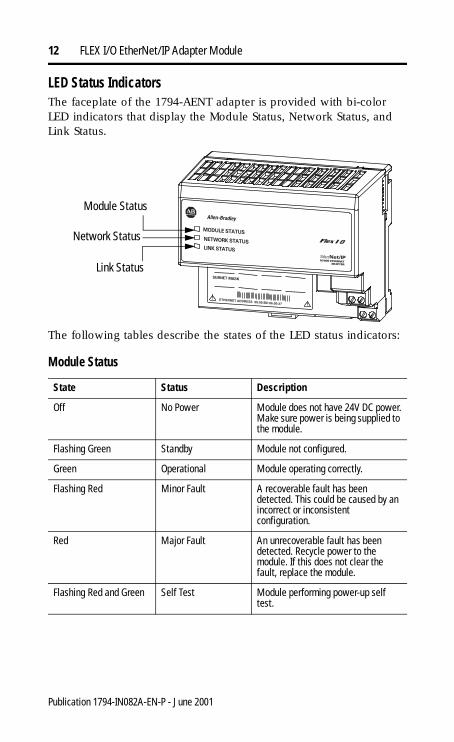
LED Status IndicatorsThe faceplate of the 1794-AENT adapter is provided with bi-color LED indicators that display the Module Status, Network Status, and Link Status.
The following tables describe the states of the LED status indicators:
Module Status
State Status Description
Off No Power Module does not have 24V DC power.Make sure power is being supplied to the module.
Flashing Green Standby Module not configured.
Green Operational Module operating correctly.
Flashing Red Minor Fault A recoverable fault has been detected. This could be caused by an incorrect or inconsistent configuration.
Red Major Fault An unrecoverable fault has been detected. Recycle power to the module. If this does not clear the fault, replace the module.
Flashing Red and Green Self Test Module performing power-up self test.
Module Status
Network Status
Link Status
Publication 1794-IN082A-EN-P - June 2001
FLEX I/O EtherNet/IP Adapter Module 13
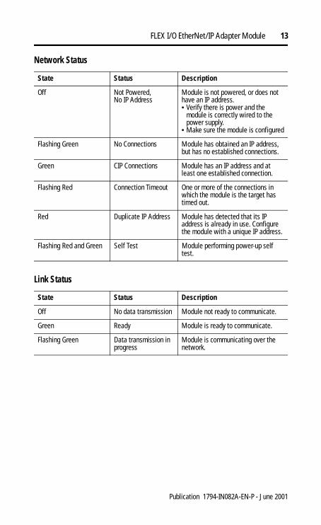
Network Status
State Status Description
Off Not Powered,No IP Address
Module is not powered, or does not have an IP address.• Verify there is power and the
module is correctly wired to the power supply.
• Make sure the module is configured
Flashing Green No Connections Module has obtained an IP address, but has no established connections.
Green CIP Connections Module has an IP address and at least one established connection.
Flashing Red Connection Timeout One or more of the connections in which the module is the target has timed out.
Red Duplicate IP Address Module has detected that its IP address is already in use. Configure the module with a unique IP address.
Flashing Red and Green Self Test Module performing power-up self test.
Link Status
State Status Description
Off No data transmission Module not ready to communicate.
Green Ready Module is ready to communicate.
Flashing Green Data transmission in progress
Module is communicating over the network.
Publication 1794-IN082A-EN-P - June 2001
14 FLEX I/O EtherNet/IP Adapter Module
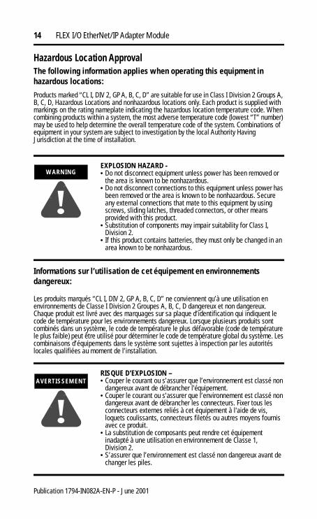
Hazardous Location ApprovalThe following information applies when operating this equipment in hazardous locations:
Products marked “CL I, DIV 2, GP A, B, C, D” are suitable for use in Class I Division 2 Groups A, B, C, D, Hazardous Locations and nonhazardous locations only. Each product is supplied with markings on the rating nameplate indicating the hazardous location temperature code. When combining products within a system, the most adverse temperature code (lowest “T” number) may be used to help determine the overall temperature code of the system. Combinations of equipment in your system are subject to investigation by the local Authority Having Jurisdiction at the time of installation.
Informations sur l’utilisation de cet équipement en environnements dangereux:
Les produits marqués “CL I, DIV 2, GP A, B, C, D” ne conviennent qu’à une utilisation en environnements de Classe I Division 2 Groupes A, B, C, D dangereux et non dangereux. Chaque produit est livré avec des marquages sur sa plaque d’identification qui indiquent le code de température pour les environnements dangereux. Lorsque plusieurs produits sont combinés dans un système, le code de température le plus défavorable (code de température le plus faible) peut être utilisé pour déterminer le code de température global du système. Les combinaisons d’équipements dans le système sont sujettes à inspection par les autorités locales qualifiées au moment de l’installation.
WARNING
!EXPLOSION HAZARD -• Do not disconnect equipment unless power has been removed or
the area is known to be nonhazardous. • Do not disconnect connections to this equipment unless power has
been removed or the area is known to be nonhazardous. Secure any external connections that mate to this equipment by using screws, sliding latches, threaded connectors, or other means provided with this product.
• Substitution of components may impair suitability for Class I, Division 2.
• If this product contains batteries, they must only be changed in an area known to be nonhazardous.
RISQUE D’EXPLOSION – • Couper le courant ou s’assurer que l’environnement est classé non
dangereux avant de débrancher l'équipement.• Couper le courant ou s'assurer que l’environnement est classé non
dangereux avant de débrancher les connecteurs. Fixer tous les connecteurs externes reliés à cet équipement à l'aide de vis, loquets coulissants, connecteurs filetés ou autres moyens fournis avec ce produit.
• La substitution de composants peut rendre cet équipement inadapté à une utilisation en environnement de Classe 1, Division 2.
• S’assurer que l’environnement est classé non dangereux avant de changer les piles.
AVERTISSEMENT
!
Publication 1794-IN082A-EN-P - June 2001
FLEX I/O EtherNet/IP Adapter Module 15
Publication 1794-IN082A-EN-P - June 2001
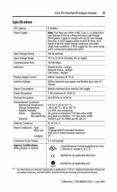
Specifications
I/O Capacity 8 modules
Power Supply Note: You must use either a NEC Class 2, a Safety Extra Low Voltage (SELV) or a Protected Extra Low Voltage (PELV) power supply to comply with the CE Low Voltage Directive. A SELV supply cannot exceed 30 Vrms, 42.4 Vpeak or 60 Vdc under normal conditions and under single fault conditions. A PELV supply has the same rating and is connected to protected earth.
Input Voltage Rating 24V dc nominal
Input Voltage Range 19.2 to 31.2V dc (includes 5% ac ripple)
Communication Rate 10/100 Mbps
Indicators Module Status - red/grnNetwork Status - red/grnLink Status - red/grn
Flexbus Output Current 640mA maximum @ 5V dc
Isolation Voltage 500Vac between user power and Flexbus (test time of 1 minute)
Power Consumption 400mA maximum from external 24V supply
Power Dissipation 7.3W maximum @ 24.0V dc
Thermal Dissipation 24.9 BTU/hr @ 24.0V dc
Environmental Conditions:Operational TemperatureStorage TemperatureRelative HumidityShock: Operating
Non-operatingVibration
0 to 55° C (32 to 131° F)–40 to 85° C (–40 to 185° F)5 to 95% non-conducting30 g peak acceleration, 11(+1)ms pulse width50 g peak acceleration, 11(+1)ms pulse widthTested 5 g @ 10–500Hz per IEC 68-2-6
Ethernet Connector RJ-45 Cat. 5
Power Conductors: TypeWire Size
Category
Copper12 gauge (4mm2) stranded maximum3/64 inch (1.2mm) insulator maximum3(1)
(1) For information on conductor routing refer to publications 1770-4.1, Industrial Automation Wiring and Grounding Guidelines, and ENET-IN001, EtherNet/IP Media Planning and Installation Manual.
Connector Screw Torque 5-7 inch-pounds
Agency CertificationsWhen product is marked
Listed Industrial Control Equipment for Class I, Division 2, Groups A, B, C, D.
Marked for all applicable directives
N223Marked for all applicable acts
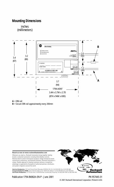
Mounting Dimensions
inches(millimeters)
A = DIN railB = Secure DIN rail approximately every 200mm
3.4(87)
3.2(80)
3.7(94)
1794-AENT
3.4H x 3.7W x 2.7D
(87H x 94W x 69D)
1.2(30)
2.0(50)
A
B
Publication 1794-IN082A-EN-P - June 2001 PN 957445-31© 2001 Rockwell International Corporation. Printed in USA


![Intermec Ethernet Adapter Guide[1]](https://img.dokumen.tips/doc/110x75/577d36861a28ab3a6b9357eb/intermec-ethernet-adapter-guide1.jpg)


