Embed Size (px)
Citation preview
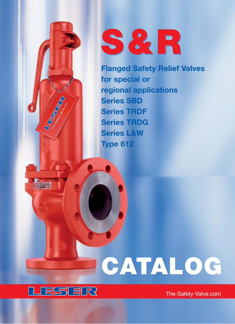
S & R S & R Flanged Safety Relief Valvesfor special or regional applicationsSeries SBDSeries TRDFSeries TRDGSeries L&WType 612
The-Safety-Valve.com
CATALOG
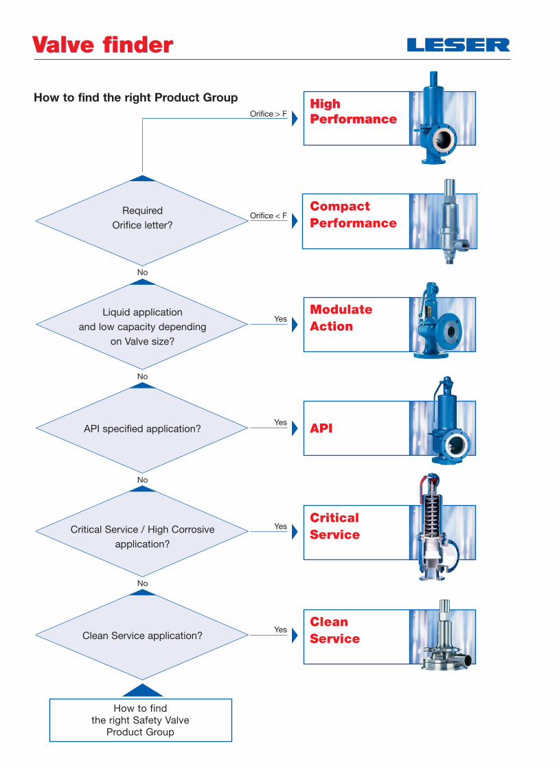
How to find the right Product Group
Valve finderValve finder
Orifice > FHigh PerformanceHigh Performance
CriticalService
How to find the right Safety Valve
Product Group
No
No
No
No
Orifice < F
Yes
Yes
Yes
Yes
CompactPerformance
ModulateAction
API
CleanService
RequiredOrifice letter?
Liquid application and low capacity depending
on Valve size?
API specified application?
Critical Service / High Corrosive application?
Clean Service application?
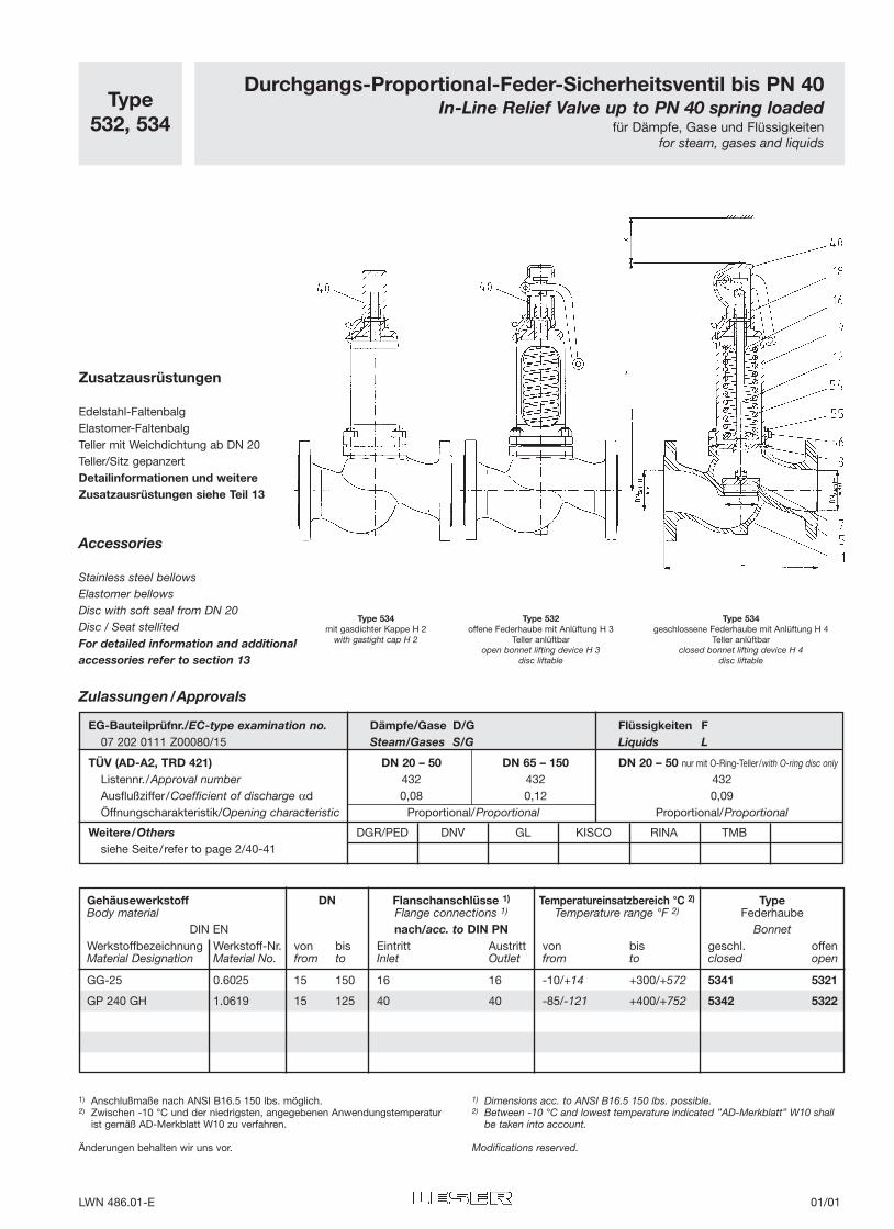
Type532, 534
Durchgangs-Proportional-Feder-Sicherheitsventil bis PN 40In-Line Relief Valve up to PN 40 spring loaded
für Dämpfe, Gase und Flüssigkeitenfor steam, gases and liquids
Zusatzausrüstungen
Edelstahl-FaltenbalgElastomer-FaltenbalgTeller mit Weichdichtung ab DN 20Teller/Sitz gepanzertDetailinformationen und weitereZusatzausrüstungen siehe Teil 13
Accessories
Stainless steel bellowsElastomer bellowsDisc with soft seal from DN 20Disc / Seat stellitedFor detailed information and additionalaccessories refer to section 13
Type 534mit gasdichter Kappe H 2
with gastight cap H 2
Type 532offene Federhaube mit Anlüftung H 3
Teller anlüftbaropen bonnet lifting device H 3
disc liftable
Type 534geschlossene Federhaube mit Anlüftung H 4
Teller anlüftbarclosed bonnet lifting device H 4
disc liftable
Gehäusewerkstoff DN Flanschanschlüsse 1) Temperatureinsatzbereich °C 2) TypeBody material Flange connections 1) Temperature range °F 2) Federhaube
DIN EN nach/acc. to DIN PN BonnetWerkstoffbezeichnung Werkstoff-Nr. von bis Eintritt Austritt von bis geschl. offenMaterial Designation Material No. from to Inlet Outlet from to closed open
GG-25 0.6025 15 150 16 16 -10/+14 +300/+572 5341 5321
GP 240 GH 1.0619 15 125 40 40 -85/-121 +400/+752 5342 5322
Zulassungen/Approvals
EG-Bauteilprüfnr./EC-type examination no. Dämpfe/Gase D/G Flüssigkeiten F07 202 0111 Z00080/15 Steam/Gases S/G Liquids L
TÜV (AD-A2, TRD 421) DN 20 – 50 DN 65 – 150 DN 20 – 50 nur mit O-Ring-Teller/with O-ring disc only
Listennr./Approval number 432 432 432Ausflußziffer/Coefficient of discharge αd 0,08 0,12 0,09Öffnungscharakteristik/Opening characteristic Proportional/Proportional Proportional/Proportional
Weitere/Others DGR/PED DNV GL KISCO RINA TMBsiehe Seite/refer to page 2/40-41
1) Anschlußmaße nach ANSI B16.5 150 lbs. möglich.2) Zwischen -10 °C und der niedrigsten, angegebenen Anwendungstemperatur
ist gemäß AD-Merkblatt W10 zu verfahren.
Änderungen behalten wir uns vor.
1) Dimensions acc. to ANSI B16.5 150 lbs. possible.2) Between -10 °C and lowest temperature indicated ”AD-Merkblatt” W10 shall
be taken into account.
Modifications reserved.
LWN 486.01-E 01/01
Nennweite, Ventilgröße Nominal Diameter, Valve size DN - 15 20 25 32 40 50 65 80 100 125 150
Nennweite, Austritt Nominal Diameter, Outlet DN - 15 20 25 32 40 50 65 80 100 125 150
Druckstufe GG Pressure rating CI PN - 16
Eintritt GS Inlet CS PN - 40
Druckstufe Austritt Pressure rating Outlet PN - GG / CI: 16, GS / CS: 40
Max. GG Max. CI p bar/bar g 16 16 16 16 16 16 16 16 16 16 16
Ansprechdruck GS Set pressure CS p bar/bar g 40 40 40 40 40 40 40 30 30 20 16
Engster Strömungsquerschnitt Flow area Ao mm2 177 316 491 804 1256 1963 1963 3217 4778 7543 12272
Engster Strömungsdurchmesser Flow diameter do mm 15 20 25 32 40 50 50 64 78 98 125
Baulänge Face to face dim. L mm 130 150 160 180 200 230 290 310 350 400 480
Bauhöhe H 2 GG Height H 2 CI H mm 235 240 240 260 340 380 380 440 530 610 665
H 3 H 3 H mm 235 240 240 260 350 390 390 450 575 650 710
H 4 GS H 4 CS H mm 235 240 240 260 360 400 400 460 575 650 710
mit Faltenbalg zus. with bellows add. H mm 35 30 30 35 55 65 60 70 75 80 95
Deckenfreiheit Height clearance x mm 150 150 150 200 200 250 250 300 350 400 450
Gewicht Weight - kg 5 6 7 9 12 16 19 26 41 54 80
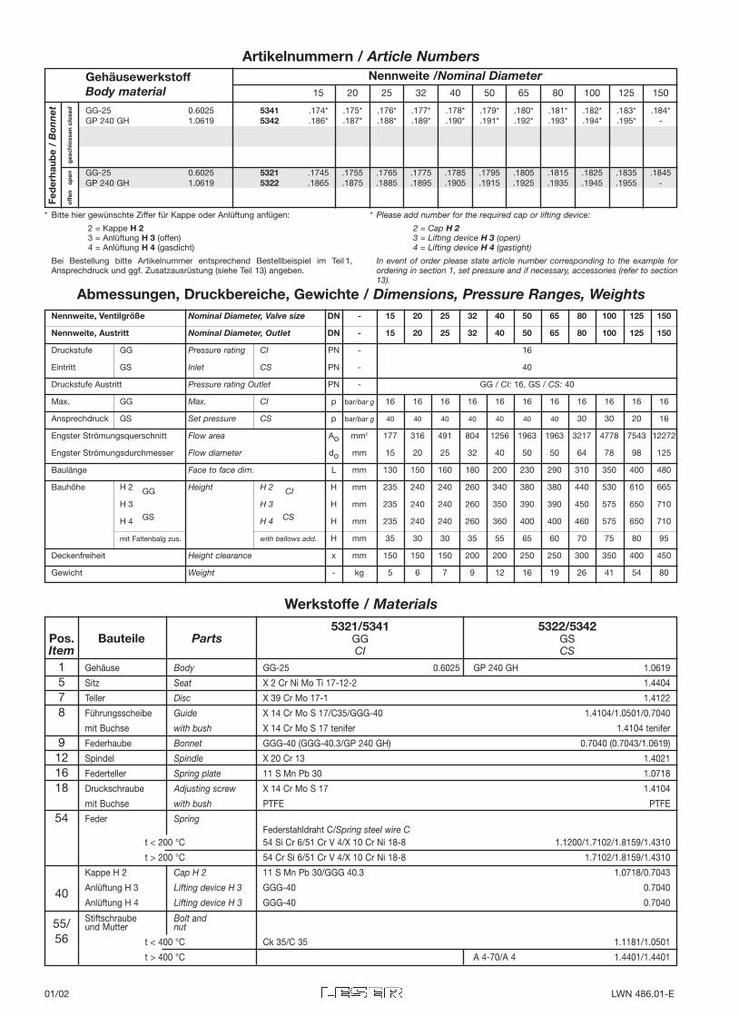
Abmessungen, Druckbereiche, Gewichte / Dimensions, Pressure Ranges, Weights
GehäusewerkstoffBody material 15 20 25 32 40 50 65 80 100 125 150
off
en
op
eng
esch
loss
en c
lose
d
Nennweite /Nominal Diameter
Fed
erha
ube
/ B
onn
etArtikelnummern / Article Numbers
* Bitte hier gewünschte Ziffer für Kappe oder Anlüftung anfügen:
2 = Kappe H 23 = Anlüftung H 3 (offen)4 = Anlüftung H 4 (gasdicht)
Bei Bestellung bitte Artikelnummer entsprechend Bestellbeispiel im Teil 1,Ansprechdruck und ggf. Zusatzausrüstung (siehe Teil 13) angeben.
* Please add number for the required cap or lifting device:
2 = Cap H 23 = Lifting device H 3 (open) 4 = Lifting device H 4 (gastight)
In event of order please state article number corresponding to the example forordering in section 1, set pressure and if necessary, accessories (refer to section13).
GG-25 0.6025 5341 .174* .175* .176* .177* .178* .179* .180* .181* .182* .183* .184*GP 240 GH 1.0619 5342 .186* .187* .188* .189* .190* .191* .192* .193* .194* .195* -
GG-25 0.6025 5321 .1745 .1755 .1765 .1775 .1785 .1795 .1805 .1815 .1825 .1835 .1845GP 240 GH 1.0619 5322 .1865 .1875 .1885 .1895 .1905 .1915 .1925 .1935 .1945 .1955 -
Gehäuse Body GG-25 0.6025 GP 240 GH 1.0619
Sitz Seat X 2 Cr Ni Mo Ti 17-12-2 1.4404
Teller Disc X 39 Cr Mo 17-1 1.4122
Führungsscheibe Guide X 14 Cr Mo S 17/C35/GGG-40 1.4104/1.0501/0.7040
mit Buchse with bush X 14 Cr Mo S 17 tenifer 1.4104 tenifer
Federhaube Bonnet GGG-40 (GGG-40.3/GP 240 GH) 0.7040 (0.7043/1.0619)
Spindel Spindle X 20 Cr 13 1.4021
Federteller Spring plate 11 S Mn Pb 30 1.0718
Druckschraube Adjusting screw X 14 Cr Mo S 17 1.4104
mit Buchse with bush PTFE PTFE
Feder SpringFederstahldraht C/Spring steel wire C
t < 200 °C 54 Si Cr 6/51 Cr V 4/X 10 Cr Ni 18-8 1.1200/1.7102/1.8159/1.4310
t > 200 °C 54 Cr Si 6/51 Cr V 4/X 10 Cr Ni 18-8 1.7102/1.8159/1.4310
Kappe H 2 Cap H 2 11 S Mn Pb 30/GGG 40.3 1.0718/0.7043
Anlüftung H 3 Lifting device H 3 GGG-40 0.7040
Anlüftung H 4 Lifting device H 3 GGG-40 0.7040
Stiftschraube Bolt andund Mutter nut
t < 400 °C Ck 35/C 35 1.1181/1.0501
t > 400 °C A 4-70/A 4 1.4401/1.4401
1578
9121618
54
40
55/56
5321/5341 5322/5342Pos. Bauteile Parts GG GSItem CI CS
Werkstoffe / Materials
01/02 LWN 486.01-E
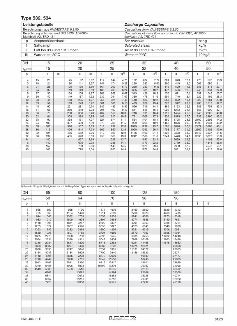
2) Bauteilprüfung für Flüssigkeiten nur mit O-Ring-Teller ! Type test approved for liquids only with o-ring-disc
DN 15 20 25 32 40 50do (mm) 15 20 25 32 40 50
I II III I II III I II III2) I II III2) I II III2) I II III2)p
4 15 20 75 92 3,02 117 144 4,71 192 237 7,72 301 370 12,1 470 578 18,95 18 24 90 111 3,37 141 174 5,27 230 285 8,63 360 445 13,5 562 695 21,16 21 28 105 130 3,69 164 203 5,77 268 333 9,46 419 520 14,8 655 813 23,17 24 32 119 149 3,99 186 233 6,24 305 381 10,2 477 596 16,0 745 931 24,98 27 36 134 168 4,27 209 262 6,67 343 429 10,9 536 671 17,1 837 1048 26,79 30 40 149 187 4,52 232 291 7,07 380 478 11,6 594 746 18,1 929 1166 28,3
10 33 44 163 205 4,77 255 321 7,45 418 526 12,2 653 822 19,1 1020 1284 29,812 39 52 193 243 5,22 301 380 8,16 493 622 13,4 770 972 20,9 1203 1519 32,714 45 60 221 281 5,64 346 439 8,82 566 719 14,4 885 1123 22,6 1383 1754 35,316 51 68 250 318 6,03 391 497 9,43 641 815 15,4 1002 1273 24,1 1565 1990 37,718 56 76 280 356 6,40 437 556 10,0 716 911 16,4 1119 1424 25,6 1748 2225 40,020 62 84 309 394 6,75 483 615 10,5 791 1008 17,3 1236 1575 27,0 1932 2460 42,222 68 92 338 431 7,07 527 674 11,1 864 1104 18,1 1350 1725 28,3 2109 2696 44,224 74 100 367 469 7,39 573 733 11,5 939 1200 18,9 1468 1876 29,6 2293 2931 46,226 80 108 396 507 7,69 619 792 12,0 1015 1297 19,7 1585 2026 30,8 2477 3166 48,128 86 116 426 544 7,98 665 850 12,5 1090 1393 20,4 1703 2177 31,9 2662 3402 49,930 92 124 455 582 8,26 712 909 12,9 1166 1490 21,1 1822 2328 33,0 2847 3637 51,632 98 132 485 620 8,53 758 968 13,3 1242 1586 21,8 1941 2478 34,1 3033 3872 53,334 140 657 8,79 1027 13,7 1682 22,5 2629 35,2 4108 55,06 149 695 9,05 1086 14,1 1779 23,2 2779 36,2 4343 56,6
38 157 733 9,30 1145 14,5 1875 23,8 2930 37,2 4578 58,140 165 770 9,54 1203 14,9 1972 24,4 3081 38,2 4813 59,6
DN 65 80 100 125 150do (mm) 50 64 78 98 98
I II I II I II I II I II I IIp
3 565 690 925 1130 1374 1679 2169 2650 3529 43124 705 866 1154 1420 1714 2109 2706 3328 4403 54155 844 1043 1382 1709 2053 2538 3241 4006 5273 65186 982 1219 1609 1998 2391 2968 3774 4685 6140 76217 1118 1396 1831 2287 2720 3397 4294 5363 6985 87248 1255 1572 2057 2576 3055 3827 4823 6041 7846 98289 1393 1749 2282 2865 3390 4256 5351 6719 8706 10931
10 1530 1925 2507 3155 3724 4686 5879 7397 9565 1203412 1805 2278 2958 3733 4393 5545 6935 8753 11282 1424014 2074 2631 3398 4311 5048 6404 7968 10109 12963 1644616 2348 2984 3847 4890 5715 7263 9021 11465 14676 1865218 2623 3337 4297 5468 6382 8122 10075 12821 2085820 2898 3690 4747 6046 7051 8981 11131 14177 2306522 3164 4043 5184 6625 7700 9840 12156 15533 2527124 3440 4396 5635 7203 8370 10699 16889 2747726 3716 4749 6088 7781 9042 11558 18245 2968328 3992 5102 6541 8360 9716 12417 19601 3188930 4270 5455 6996 8938 10392 13276 20957 3409632 4549 5808 7453 9516 14135 22313 3630234 6161 10095 14994 23669 3850836 6514 10673 15853 25025 4071438 6867 11251 16712 26381 4292040 7220 11830 17571 27737 45126
Leistungstabelle Discharge CapacitiesBerechnungen aus VALVESTAR® 6.2.50 Calculations from VALVESTAR® 6.2.50Berechnung entsprechend DIN 3320, AD2000- Calculations of mass flow according to DIN 3320, AD2000-Merkblatt A2, TRD 421 Merkblatt A2, TRD 421
p Ansprechüberdruck Set pressure bar gI Sattdampf Saturated steam kg/hII Luft bei 0°C und 1013 mbar Air at 0°C and 1013 mbar mn
3/hIII Wasser bei 20°C Water at 20°C 103kg/h
Type 532, 534
LWN 486.01-E 01/03
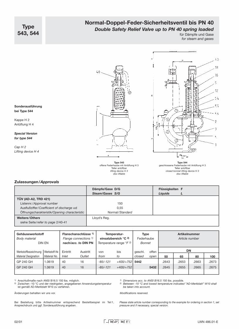
Normal-Doppel-Feder-Sicherheitsventil bis PN 40Double Safety Relief Valve up to PN 40 spring loaded
für Dämpfe und Gasefor steam and gases
Type543, 544
Type 543offene Federhaube mit Anlüftung H 3
Teller anlüftbarlifting device H 3
disc liftable
Type 544geschlossene Federhaube mit Anlüftung H 3
Teller anlüftbarclosed bonnet lifting device H 3
disc liftable
Sonderausführung
bei Type 544
Kappe H 2Anlüftung H 4
Special Version
for type 544
Cap H 2Lifting device H 4
Bei Bestellung bitte Artikelnummer entsprechend Bestellbeispiel im Teil 1,Ansprechdruck und ggf. Sonderausführung angeben.
Please state article number corresponding to the example for ordering in section 1, setpressure and if necessary, special version.
Gehäusewerkstoff Flanschanschlüsse 1) Temperatur- Type ArtikelnummerBody material Flange connections 1) einsatzbereich °C 2) Federhaube Article number
DIN EN nach/acc. to DIN PN Temperature range °F 2) Bonnet
DNWerkstoffbezeichnung Werkstoff-Nr. Eintritt Austritt von bis geschl. offenMaterial Designation Material No. Inlet Outlet from to closed open 50 65 80 100
GP 240 GH 1.0619 40 16 -85/-121 +400/+752 5442 .2643 .2653 .2663 .2673
GP 240 GH 1.0619 40 16 -85/-121 +400/+752 5432 .2645 .2655 .2665 .2675
Zulassungen/Approvals
Dämpfe/Gase D/G Flüssigkeiten FSteam/Gases S/G Liquids L
TÜV (AD-A2, TRD 421)Listennr./Approval number 150Ausflußziffer/Coefficient of discharge αd 0,55Öffnungscharakteristik/Opening characteristic Normal/Standard
Weitere/Others Lloyd’s Reg.siehe Seite/refer to page 2/40-41
1) Anschlußmaße nach ANSI B16.5 150 lbs. möglich.2) Zwischen -10 °C und der niedrigsten, angegebenen Anwendungstemperatur
ist gemäß AD-Merkblatt W10 zu verfahren.
Änderungen behalten wir uns vor.
1) Dimensions acc. to ANSI B16.5 150 lbs. possible.2) Between -10 °C and lowest temperature indicated ”AD-Merkblatt” W10 shall
be taken into account.
Modifications reserved.
02/01 LWN 486.01-E
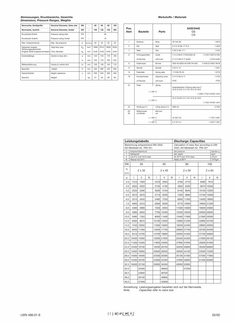
Nennweite, Ventilgröße Nominal Diameter, Valve size DN - 50 65 80 100
Nennweite, Austritt Nominal Diameter, Outlet DN - 100 125 150 200
Druckstufe Eintritt Pressure rating Inlet PN - 40
Druckstufe Austritt Pressure rating Outlet PN - 16
Max. Ansprechdruck Max. Set pressure p bar/bar g 40 40 35 30
Ao mm2 1608 2514 3926 6434
do mm 2x32 2x40 2x50 2x64
Schenkellänge Centre to face dim. a mm 145 155 170 195
b mm 150 170 195 225
Mittenentfernung Centre to centre dim. m mm 120 130 145 175
Bauhöhe Height H mm 335 380 440 565
Deckenfreiheit Height clearance x mm 200 250 300 350
Gewicht Weight - kg 27 35 58 83
Pos. 5432/5442Item Bauteile Parts GS
CS
I II III I II III I II III I II III
2.0 1510 1950 2370 3050 3700 4770 6060 7810
3.0 2020 2620 3150 4100 4920 6400 8070 10500
4.0 2520 3290 3930 5150 6140 8040 10100 13200
5.0 3010 3970 4710 6200 7350 9680 12100 15900
6.0 3510 4640 5480 7250 8560 11300 14000 18600
7.0 4000 5310 6260 8300 9770 13000 16000 21200
8.0 4490 5980 7030 9350 11000 14600 18000 23900
9.0 4990 6650 7790 10400 12200 16200 20000 26600
10.0 5480 7320 8560 11400 13400 17900 21900 29300
12.0 6460 8670 10100 13500 15800 21200 25800 34700
14.0 7440 10000 11600 15600 18200 24400 29800 40000
16.0 8430 11300 13200 17700 20600 27700 33700 45400
18.0 9410 12700 14700 19800 23000 31000 37700 50800
20.0 10400 14000 16300 21900 25400 34300 41600 56100
22.0 11400 15400 17800 24000 27800 37600 45600 61600
24.0 12400 16700 19400 26100 30200 40800 49500 66900
26.0 13400 18000 20900 28200 32600 44100 53500 72300
28.0 14400 19400 22500 30300 35100 47400 57500 77600
30.0 15400 20700 24000 32400 37600 50600 61500 83000
32.0 16400 22100 25600 34500 40000 53900
34.0 23400 36600 57200
36.0 24800 38700
38.0 26100 40800
40.0 27500 42900
p
2 x 32 2 x 40 2 x 50 2 x 64
DN 50 65 80 100
do
(mm)
Abmessungen, Druckbereiche, GewichteDimensions, Pressure Ranges, Weights
1 Gehäuse Body GP 240 GH 1.0619
5 Sitz Seat X 2 Cr Ni Mo 17-12-2 1.4404
7 Teller Disc X 39 Cr Mo 17-1 1.4122
8 Führungsscheibe Guide X 14 CrMoS 17/C35/GGG-40 1.4104/1.0501/0.7040
mit Buchse with bush X 14 Cr Mo S 17 tenifer 1.4104 tenifer
9 Federhaube Bonnet GGG-40 (GGG-40.3/GP 240 GH) 0.7040 (0.7043/1.0619)
12 Spindel Spindle X 20 Cr 13 1.4021
16 Federteller Spring plate 11 S Mn Pb 30 1.0718
18 Druckschraube Adjusting screw X 14 Cr Mo S 17 1.4104
mit Buchse with bush PTFE PTFE
54 Feder SpringFederstahldraht C/Spring steel wire C
t < 200° C54 Si Cr 6/51 Cr V 4/X 10 Cr Ni 18-8
1.1200/1.7102/1.8159/1.4310
t > 200° C54 Cr Si 6/51 Cr V 4/X 10 Cr Ni 18-8
1.7102/1.8159/1.4310
40 Anlüftung H 3 Lifting device H 3 GGG-40 0.7040
55/ Stiftschraube Bolt and56 und Mutter nut
t < 400° C Ck 35/C 35 1.1181/1.0501
t > 400° C A 4-70/ A 4 1.4401/1.4401
Werkstoffe / Materials
Gesamter engster Total flow areaStrömungsquerschnittEngster Strömungsdurchmesser Flow diameter
LeistungstabelleBerechnung entsprechend DIN 3320, AD-Merkblatt A2, TRD 421
Discharge CapacitiesCalculation of mass flow according to DIN3320, AD-Merkblatt A2, TRD 421
p Ansprechüberdruck Set pressure bar/bar gI Sattdampf Sat. steam kg/hII Luft 0°C und 1013 mbar Air 32°F and 1013 mbar m3n/hIII Wasser bei 20°C Water at 68°F 103 kg/h
Anmerkung: Leistungsangaben beziehen sich auf die Nennweite.Note: Capacities refer to valve size.
LWN 486.01-E 02/02
Gehäusewerkstoff Flanschanschlüsse ArtikelnummerBody material Flange connections Article number
DIN EN nach/acc. to DIN PN
Werkstoffbezeichnung Werkstoff-Nr. Eintritt Austritt DN
Material Designation Material No. Inlet Outlet 20 25 32 40 50 65 80 100 125 150GG-25 0.6025 16 16 4401 .3501 .3511 .3521 .3531 .3541 .3551 .3561 .3571 .3581 .3591
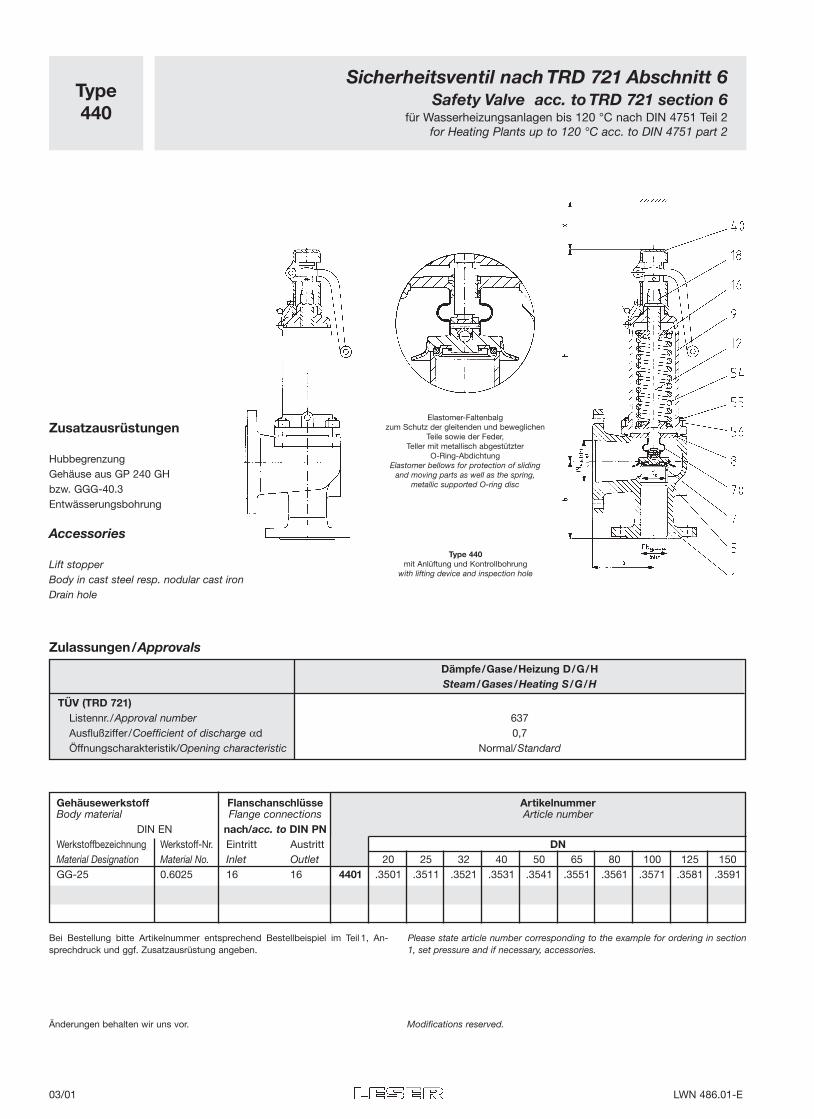
Type
440
Sicherheitsventil nach TRD 721 Abschnitt 6
Safety Valve acc. to TRD 721 section 6für Wasserheizungsanlagen bis 120 °C nach DIN 4751 Teil 2
for Heating Plants up to 120 °C acc. to DIN 4751 part 2
Zusatzausrüstungen
HubbegrenzungGehäuse aus GP 240 GHbzw. GGG-40.3Entwässerungsbohrung
Accessories
Lift stopperBody in cast steel resp. nodular cast ironDrain hole
Type 440
mit Anlüftung und Kontrollbohrungwith lifting device and inspection hole
Änderungen behalten wir uns vor. Modifications reserved.
Elastomer-Faltenbalgzum Schutz der gleitenden und beweglichen
Teile sowie der Feder, Teller mit metallisch abgestützter
O-Ring-AbdichtungElastomer bellows for protection of sliding
and moving parts as well as the spring,metallic supported O-ring disc
Bei Bestellung bitte Artikelnummer entsprechend Bestellbeispiel im Teil 1, An-sprechdruck und ggf. Zusatzausrüstung angeben.
Please state article number corresponding to the example for ordering in section1, set pressure and if necessary, accessories.
Zulassungen/Approvals
Dämpfe/Gase/Heizung D/G/H
Steam/Gases/Heating S/G/H
TÜV (TRD 721)
Listennr./Approval number 637Ausflußziffer/Coefficient of discharge αd 0,7Öffnungscharakteristik/Opening characteristic Normal/Standard
03/01 LWN 486.01-E
Gehäuse Body GG-25 (GGG-40.3/GP 240 GH) 0.6025 (0.7043/1.0619)
Sitz Seat X2 Cr Ni Mo 17-12-2 1.4404
O-Ring-Teller O-Ring-Disc X 39 Cr Mo 17-1/EPDM 1.4122/EPDM
Führungsscheibe Guide X 14 Cr Mo S 17/C35/GGG-40 1.4104/1.0501/0.7040
mit Buchse with bush X 14 Cr Mo S 17 tenifer 1.4104 tenifer
Federhaube Bonnet GGG-40 0.7040
Spindel Spindle X 20 Cr 13 1.4021
Federteller Spring plate 11 S Mn Pb 30 1.0718
Druckschraube Adjusting screw X 14 Cr Mo S 17/X 2 Cr Ni Mo 17-12-2 1.4104/1.4404
mit Buchse with bush PTFE PTFE
Feder Spring Federstahldraht C/Spring steel wire C54 Si Cr 6/51 Cr V 4/X 10 Cr Ni 18-8 1.1200/1.7102/1.8159/1.4310
Anlüftung H 3 Lifting device H 3 GGG-40 0.7040
Stiftschraube Bolt
Mutter nut Ck 35/C 35 1.1181/1.0501
Faltenbalg Bellows EPDM EPDM
1
5
7
8
9
12
16
18
54
40
55/
56
70
4401Pos. Bauteile Parts GGItem CI
Werkstoffe / Materials
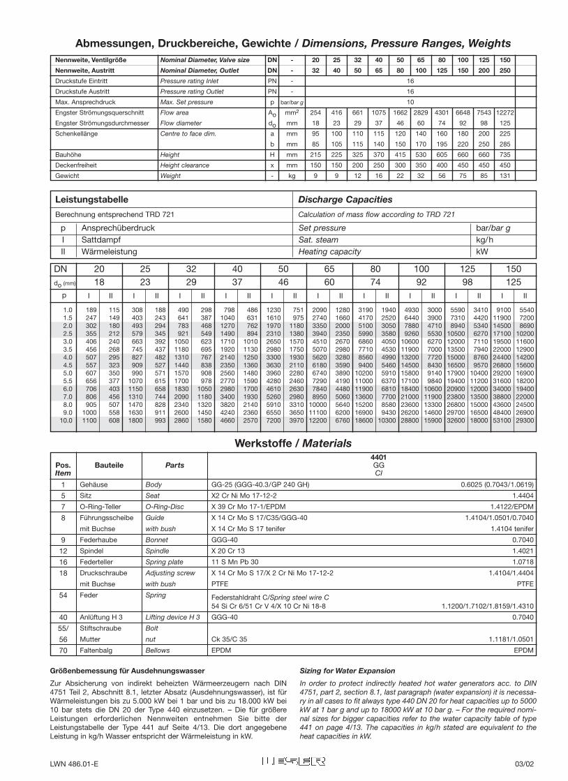
Nennweite, Ventilgröße Nominal Diameter, Valve size DN - 20 25 32 40 50 65 80 100 125 150
Nennweite, Austritt Nominal Diameter, Outlet DN - 32 40 50 65 80 100 125 150 200 250
Druckstufe Eintritt Pressure rating Inlet PN - 16
Druckstufe Austritt Pressure rating Outlet PN - 16
Max. Ansprechdruck Max. Set pressure p bar/bar g 10
Engster Strömungsquerschnitt Flow area Ao mm2 254 416 661 1075 1662 2829 4301 6648 7543 12272
Engster Strömungsdurchmesser Flow diameter do mm 18 23 29 37 46 60 74 92 98 125
Schenkellänge Centre to face dim. a mm 95 100 110 115 120 140 160 180 200 225
b mm 85 105 115 140 150 170 195 220 250 285
Bauhöhe Height H mm 215 225 325 370 415 530 605 660 660 735
Deckenfreiheit Height clearance x mm 150 150 200 250 300 350 400 450 450 450
Gewicht Weight - kg 9 9 12 16 22 32 56 75 85 131
Abmessungen, Druckbereiche, Gewichte / Dimensions, Pressure Ranges, Weights
DN 20 25 32 40 50 65 80 100 125 150do (mm) 18 23 29 37 46 60 74 92 98 125
I II I II I II I II I II I II I II I II I II I IIp
1.0 189 115 308 188 490 298 798 486 1230 751 2090 12801.5 247 149 403 243 641 387 1040 631 1610 975 2740 16602.0 302 180 493 294 783 468 1270 762 1970 1180 3350 20002.5 355 212 579 345 921 549 1490 894 2310 1380 3940 23503.0 406 240 663 392 1050 623 1710 1010 2650 1570 4510 26703.5 456 268 745 437 1180 695 1920 1130 2980 1750 5070 29804.0 507 295 827 482 1310 767 2140 1250 3300 1930 5620 32804.5 557 323 909 527 1440 838 2350 1360 3630 2110 6180 35905.0 607 350 990 571 1570 908 2560 1480 3960 2280 6740 38905.5 656 377 1070 615 1700 978 2770 1590 4280 2460 7290 41906.0 706 403 1150 658 1830 1050 2980 1700 4610 2630 7840 44807.0 806 456 1310 744 2090 1180 3400 1930 5260 2980 8950 50608.0 905 507 1470 828 2340 1320 3820 2140 5910 3310 10000 56409.0 1000 558 1630 911 2600 1450 4240 2360 6550 3650 11100 6200
10.0 1100 608 1800 993 2860 1580 4660 2570 7200 3970 12200 6760
3190 1940 4930 3000 5590 3410 9100 55404170 2520 6440 3900 7310 4420 11900 72005100 3050 7880 4710 8940 5340 14500 86905990 3580 9260 5530 10500 6270 17100 102006860 4050 10600 6270 12000 7110 19500 116007710 4530 11900 7000 13500 7940 22000 129008560 4990 13200 7720 15000 8760 24400 142009400 5460 14500 8430 16500 9570 26800 15600
10200 5910 15800 9140 17900 10400 29200 1690011000 6370 17100 9840 19400 11200 31600 1820011900 6810 18400 10600 20900 12000 34000 1940013600 7700 21000 11900 23800 13500 38800 2200015200 8580 23600 13300 26800 15000 43600 2450016900 9430 26200 14600 29700 16500 48400 2690018600 10300 28800 15900 32600 18000 53100 29300
Größenbemessung für Ausdehnungswasser
Zur Absicherung von indirekt beheizten Wärmeerzeugern nach DIN4751 Teil 2, Abschnitt 8.1, letzter Absatz (Ausdehnungswasser), ist fürWärmeleistungen bis zu 5.000 kW bei 1 bar und bis zu 18.000 kW bei10 bar stets die DN 20 der Type 440 einzusetzen. – Die für größereLeistungen erforderlichen Nennweiten entnehmen Sie bitte derLeistungstabelle der Type 441 auf Seite 4/13. Die dort angegebeneLeistung in kg/h Wasser entspricht der Wärmeleistung in kW.
Sizing for Water Expansion
In order to protect indirectly heated hot water generators acc. to DIN4751, part 2, section 8.1, last paragraph (water expansion) it is necessa-ry in all cases to fit always type 440 DN 20 for heat capacities up to 5000kW at 1 bar g and up to 18000 kW at 10 bar g. – For the required nomi-nal sizes for bigger capacities refer to the water capacity table of type441 on page 4/13. The capacities in kg/h stated are equivalent to theheat capacities in kW.
Leistungstabelle Discharge Capacities
Berechnung entsprechend TRD 721 Calculation of mass flow according to TRD 721
p Ansprechüberdruck Set pressure bar/bar gI Sattdampf Sat. steam kg/hII Wärmeleistung Heating capacity kW
LWN 486.01-E 03/02
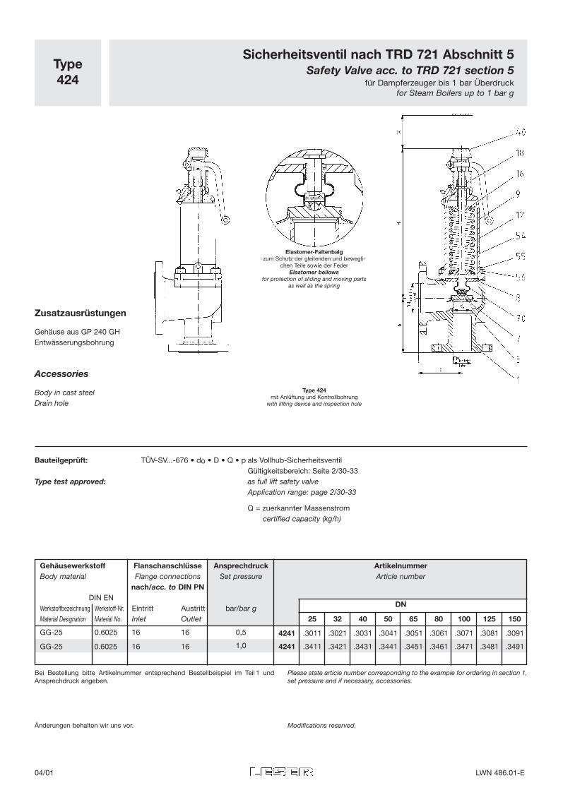
Type424
Sicherheitsventil nach TRD 721 Abschnitt 5Safety Valve acc. to TRD 721 section 5
für Dampferzeuger bis 1 bar Überdruckfor Steam Boilers up to 1 bar g
Elastomer-Faltenbalgzum Schutz der gleitenden und bewegli-
chen Teile sowie der FederElastomer bellows
for protection of sliding and moving partsas well as the spring
Type 424mit Anlüftung und Kontrollbohrung
with lifting device and inspection hole
Bauteilgeprüft: TÜV-SV...-676 • do • D • Q • p als Vollhub-SicherheitsventilGültigkeitsbereich: Seite 2/30-33
Type test approved: as full lift safety valveApplication range: page 2/30-33
Q = zuerkannter Massenstromcertified capacity (kg/h)
Änderungen behalten wir uns vor. Modifications reserved.
Bei Bestellung bitte Artikelnummer entsprechend Bestellbeispiel im Teil 1 undAnsprechdruck angeben.
Please state article number corresponding to the example for ordering in section 1,set pressure and if necessary, accessories.
Zusatzausrüstungen
Gehäuse aus GP 240 GHEntwässerungsbohrung
Accessories
Body in cast steelDrain hole
Gehäusewerkstoff Flanschanschlüsse Ansprechdruck ArtikelnummerBody material Flange connections Set pressure Article number
nach/acc. to DIN PN
DNDIN EN
Werkstoffbezeichnung Werkstoff-Nr. Eintritt Austritt bar/bar gMaterial Designation Material No. Inlet Outlet 25 32 40 50 65 80 100 125 150
GG-25 0.6025 16 16 0,5 4241 .3011 .3021 .3031 .3041 .3051 .3061 .3071 .3081 .3091
GG-25 0.6025 16 16 1,0 4241 .3411 .3421 .3431 .3441 .3451 .3461 .3471 .3481 .3491
04/01 LWN 486.01-E
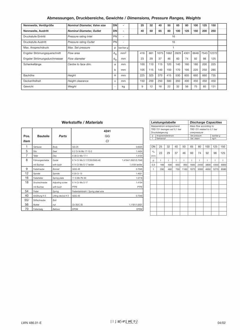
DN 25 32 40 50 65 80 100 125 150
do 23 29 37 46 60 74 92 98 125(mm)
I I I I I I I I I
0,5 189 400 650 950 1600 2450 3800 4350 6900
1 290 460 750 1160 1975 3000 4650 5270 8580
p
Nennweite, Ventilgröße Nominal Diameter, Valve size DN - 25 32 40 50 65 80 100 125 150
Nennweite, Austritt Nominal Diameter, Outlet DN - 40 50 65 80 100 125 150 200 250
Druckstufe Eintritt Pressure rating Inlet PN - 16
Druckstufe Austritt Pressure rating Outlet PN - 16
Max. Ansprechdruck Max. Set pressure p bar/bar g 1
Engster Strömungsquerschnitt Flow area Ao mm2 416 661 1075 1662 2829 4301 6648 7543 12272
Engster Strömungsdurchmesser Flow diameter do mm 23 29 37 46 60 74 92 98 125
Schenkellänge Centre to face dim. a mm 100 110 115 120 140 160 180 200 225
b mm 105 115 140 150 170 195 220 250 285
Bauhöhe Height H mm 225 325 370 415 530 605 660 660 735
Deckenfreiheit Height clearance x mm 150 200 250 300 350 400 450 450 450
Gewicht Weight - kg 9 12 16 22 32 56 75 85 131
Abmessungen, Druckbereiche, Gewichte / Dimensions, Pressure Ranges, Weights
Gehäuse Body GG-25 0.6025
Sitz Seat X 2 Cr Ni Mo 17-12-2 1.4404
Teller Disc X 39 Cr Mo 17-1 1.4122
Führungsscheibe Guide X 14 Cr Mo S 17/C35/GGG-40 1.4104/1.0501/0.7040
mit Buchse with bush X 14 Cr Mo S 17 tenifer 1.4104 tenifer
Federhaube Bonnet GGG-40 0.7040
Spindel Spindle X 20 Cr 13 1.4021
Federteller Spring plate 11 S Mn Pb 30 1.0718
Druckschraube Adjusting screw X 14 Cr Mo S 17 1.4104
mit Buchse with bush PTFE PTFE
Feder Spring Federstahldraht / Spring steel wire
Anlüftung H 3 Lifting device H 3 GGG-40 0.7040
Stiftschraube Bolt
Mutter nut Ck 35/C 35 1.1181/1.0501
Faltenbalg Bellows EPDM EPDM
1578
9121618
544055/5670
4241
Pos. Bauteile Parts GG
Item CI
Werkstoffe / Materials LeistungstabelleMassenstrom entsprechend TRD 721 bezogen auf 0,1 barDrucksteigerung
Discharge CapacitiesMass flow according to TRD 721 related to 0,1 bar overpressure
p Ansprechüberdruck Set pressure bar/bar gI Sattdampf Sat. steam kg/h
LWN 486.01-E 04/02
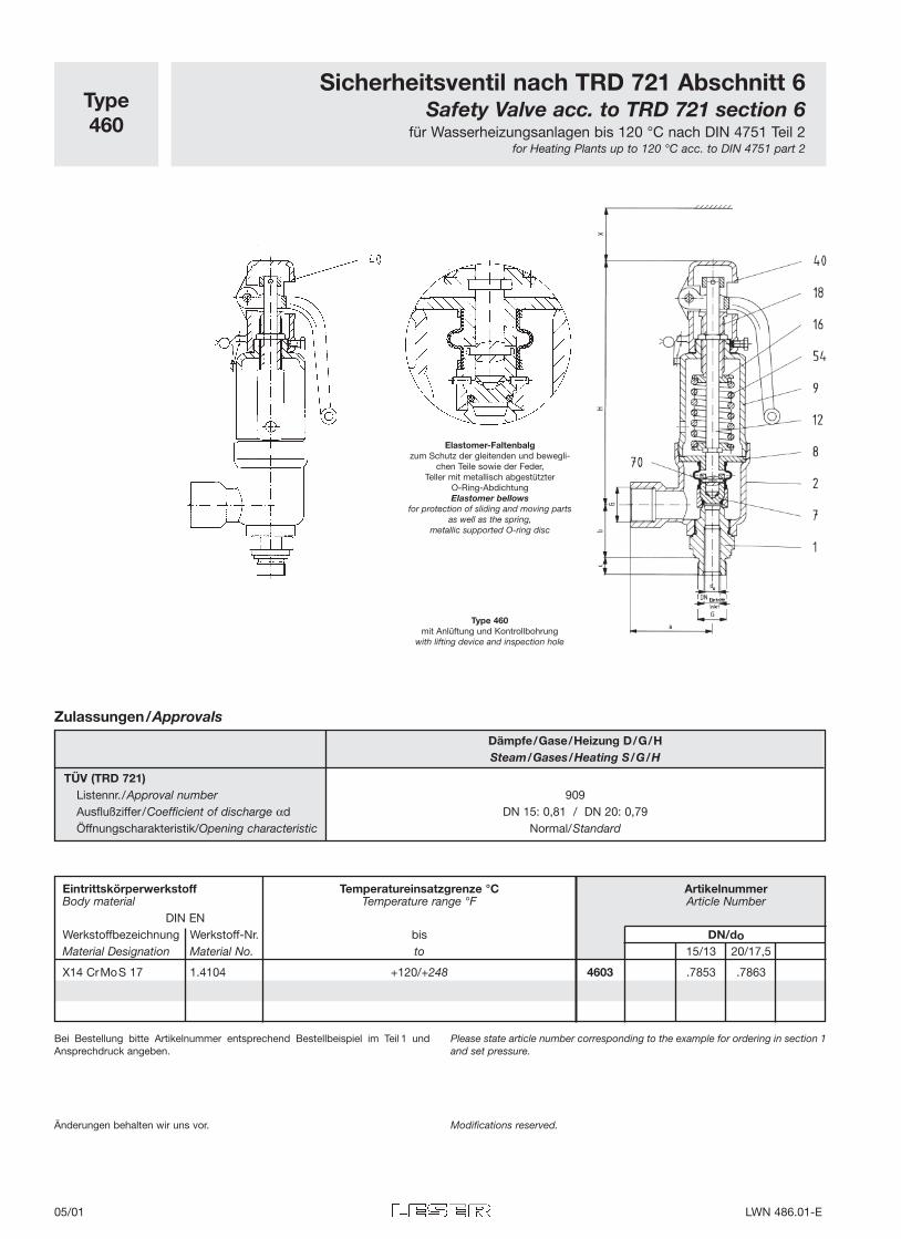
Type460
Sicherheitsventil nach TRD 721 Abschnitt 6Safety Valve acc. to TRD 721 section 6
für Wasserheizungsanlagen bis 120 °C nach DIN 4751 Teil 2for Heating Plants up to 120 °C acc. to DIN 4751 part 2
Änderungen behalten wir uns vor. Modifications reserved.
Elastomer-Faltenbalgzum Schutz der gleitenden und bewegli-
chen Teile sowie der Feder,Teller mit metallisch abgestützter
O-Ring-AbdichtungElastomer bellows
for protection of sliding and moving partsas well as the spring,
metallic supported O-ring disc
Type 460mit Anlüftung und Kontrollbohrung
with lifting device and inspection hole
Bei Bestellung bitte Artikelnummer entsprechend Bestellbeispiel im Teil 1 undAnsprechdruck angeben.
Please state article number corresponding to the example for ordering in section 1and set pressure.
Eintrittskörperwerkstoff Temperatureinsatzgrenze °C ArtikelnummerBody material Temperature range °F Article Number
DIN ENWerkstoffbezeichnung Werkstoff-Nr. bis DN/doMaterial Designation Material No. to 15/13 20/17,5
X14 CrMoS 17 1.4104 +120/+248 4603 .7853 .7863
Zulassungen/Approvals
Dämpfe/Gase/Heizung D/G/HSteam/Gases/Heating S/G/H
TÜV (TRD 721)Listennr./Approval number 909Ausflußziffer/Coefficient of discharge αd DN 15: 0,81 / DN 20: 0,79Öffnungscharakteristik/Opening characteristic Normal/Standard
05/01 LWN 486.01-E
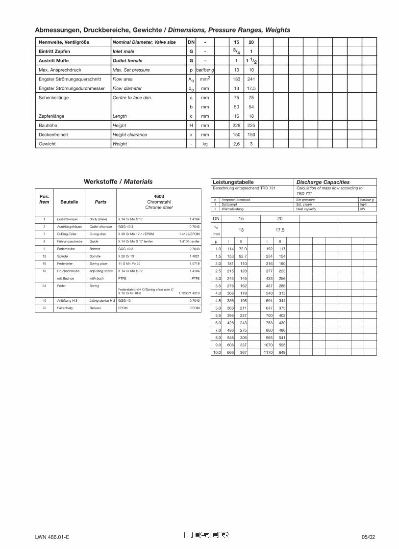
Nennweite, Ventilgröße Nominal Diameter, Valve size DN - 15 20
Eintritt Zapfen Inlet male G - 3/4 1
Austritt Muffe Outlet female G - 1 1 1/2
Max. Ansprechdruck Max. Set pressure p bar/bar g 10 10
Engster Strömungsquerschnitt Flow area Ao mm2 133 241
Engster Strömungsdurchmesser Flow diameter do mm 13 17,5
Schenkellänge Centre to face dim. a mm 75 75
b mm 50 54
Zapfenlänge Length c mm 16 18
Bauhöhe Height H mm 228 225
Deckenfreiheit Height clearance x mm 150 150
Gewicht Weight - kg 2,6 3
DN 15 20
do13 17,5
(mm)
I II I II
1.0 114 72.0 192 117
1.5 153 92.7 254 154
2.0 181 110 316 190
2.5 215 128 377 223
3.0 245 145 433 256
3.5 276 162 487 286
4.0 306 178 540 315
4.5 336 195 594 344
5.0 366 211 647 373
5.5 396 227 700 402
6.0 426 243 753 430
7.0 486 275 860 486
8.0 546 306 965 541
9.0 606 337 1070 595
10.0 666 367 1170 649
p
Abmessungen, Druckbereiche, Gewichte / Dimensions, Pressure Ranges, Weights
Pos. 4603Item Bauteile Parts Chromstahl
Chrome steel
Werkstoffe / Materials
1 Eintrittskörper Body (Base) X 14 Cr Mo S 17 1.4104
2 Austrittsgehäuse Outlet chamber GGG-40.3 0.7043
7 O-Ring-Teller O-ring-disc X 39 Cr Mo 17-1 /EPDM 1.4122/EPDM
8 Führungsscheibe Guide X 14 Cr Mo S 17 tenifer 1.4104 tenifer
9 Federhaube Bonnet GGG-40.3 0.7043
12 Spindel Spindle X 20 Cr 13 1.4021
16 Federteller Spring plate 11 S Mn Pb 30 1.0718
18 Druckschraube Adjusting screw X 14 Cr Mo S 17 1.4104
mit Buchse with bush PTFE PTFE
54 Feder SpringFederstahldraht C/Spring steel wire CX 10 Cr Ni 18-8 1.1200/1.4310
40 Anlüftung H 3 Lifting device H 3 GGG-40 0.7040
70 Faltenbalg Bellows EPDM EPDM
LeistungstabelleBerechnung entsprechend TRD 721
Discharge CapacitiesCalculation of mass flow according to TRD 721
p Ansprechüberdruck Set pressure bar/bar gI Sattdampf Sat. steam kg/hII Wärmeleistung Heat capacity kW
LWN 486.01-E 05/02
Eintrittskörperwerkstoff Ansprechdruck ArtikelnummerBody materialSet pressure Article Number
DIN ENWerkstoffbezeichnung Werkstoff-Nr. bar DN/doMaterial Designation Material No. bar g 15/13 20/17,5
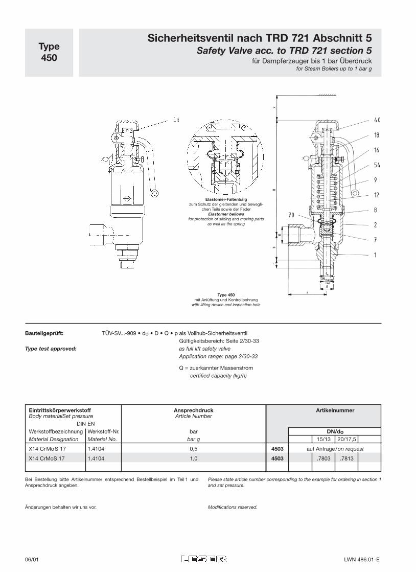
X14 CrMoS 17 1.4104 0,5 4503 auf Anfrage/on request
X14 CrMoS 17 1.4104 1,0 4503 .7803 .7813
Type450
Sicherheitsventil nach TRD 721 Abschnitt 5Safety Valve acc. to TRD 721 section 5
für Dampferzeuger bis 1 bar Überdruckfor Steam Boilers up to 1 bar g
Änderungen behalten wir uns vor. Modifications reserved.
Elastomer-Faltenbalgzum Schutz der gleitenden und bewegli-
chen Teile sowie der FederElastomer bellows
for protection of sliding and moving partsas well as the spring
Type 450mit Anlüftung und Kontrollbohrung
with lifting device and inspection hole
Bauteilgeprüft: TÜV-SV...-909 • do • D • Q • p als Vollhub-SicherheitsventilGültigkeitsbereich: Seite 2/30-33
Type test approved: as full lift safety valveApplication range: page 2/30-33
Q = zuerkannter Massenstromcertified capacity (kg/h)
Bei Bestellung bitte Artikelnummer entsprechend Bestellbeispiel im Teil 1 undAnsprechdruck angeben.
Please state article number corresponding to the example for ordering in section 1and set pressure.
06/01 LWN 486.01-E
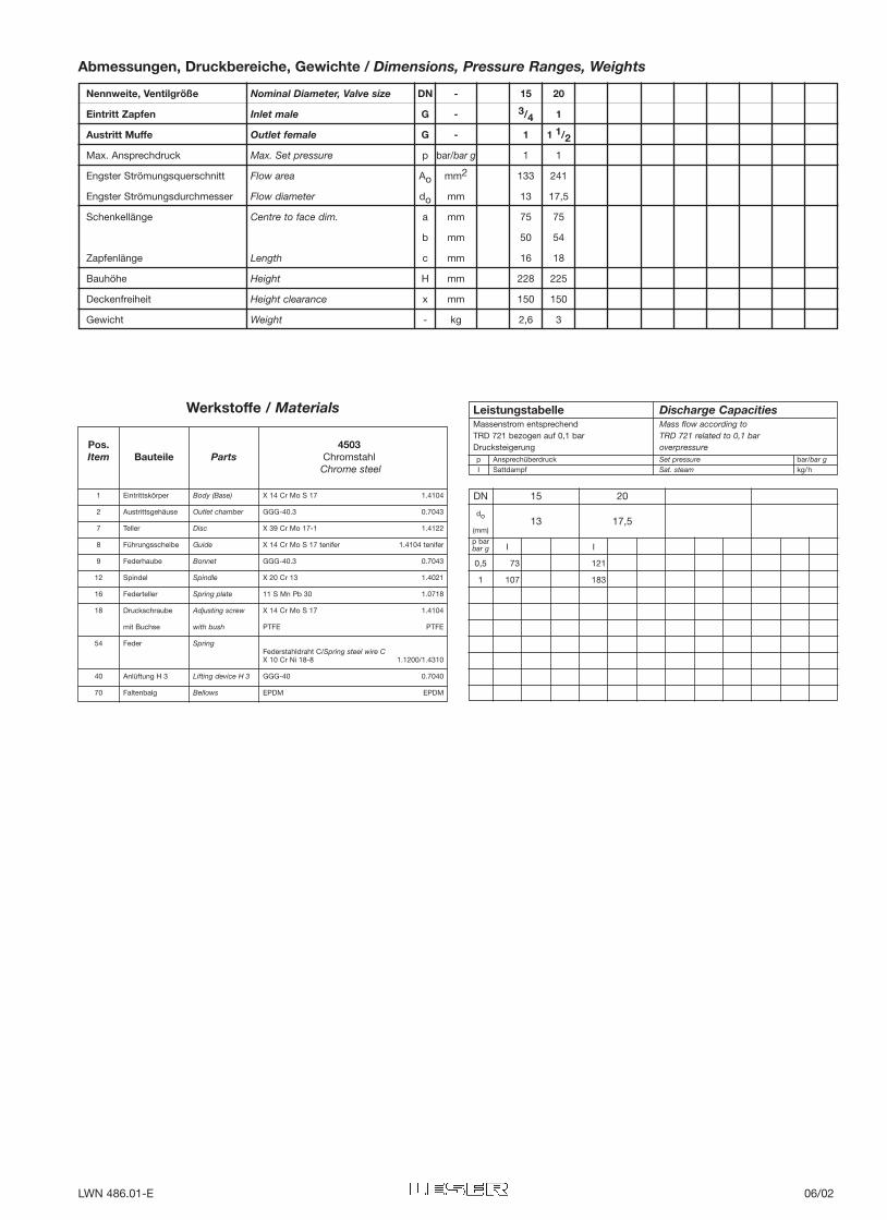
Nennweite, Ventilgröße Nominal Diameter, Valve size DN - 15 20
Eintritt Zapfen Inlet male G - 3/4 1
Austritt Muffe Outlet female G - 1 1 1/2
Max. Ansprechdruck Max. Set pressure p bar/bar g 1 1
Engster Strömungsquerschnitt Flow area Ao mm2 133 241
Engster Strömungsdurchmesser Flow diameter do mm 13 17,5
Schenkellänge Centre to face dim. a mm 75 75
b mm 50 54
Zapfenlänge Length c mm 16 18
Bauhöhe Height H mm 228 225
Deckenfreiheit Height clearance x mm 150 150
Gewicht Weight - kg 2,6 3
DN 15 20
do13 17,5
(mm)
I I
0,5 73 121
1 107 183
p barbar g
Abmessungen, Druckbereiche, Gewichte / Dimensions, Pressure Ranges, Weights
1 Eintrittskörper Body (Base) X 14 Cr Mo S 17 1.4104
2 Austrittsgehäuse Outlet chamber GGG-40.3 0.7043
7 Teller Disc X 39 Cr Mo 17-1 1.4122
8 Führungsscheibe Guide X 14 Cr Mo S 17 tenifer 1.4104 tenifer
9 Federhaube Bonnet GGG-40.3 0.7043
12 Spindel Spindle X 20 Cr 13 1.4021
16 Federteller Spring plate 11 S Mn Pb 30 1.0718
18 Druckschraube Adjusting screw X 14 Cr Mo S 17 1.4104
mit Buchse with bush PTFE PTFE
54 Feder SpringFederstahldraht C/Spring steel wire CX 10 Cr Ni 18-8 1.1200/1.4310
40 Anlüftung H 3 Lifting device H 3 GGG-40 0.7040
70 Faltenbalg Bellows EPDM EPDM
Pos. 4503Item Bauteile Parts Chromstahl
Chrome steel
Werkstoffe / Materials LeistungstabelleMassenstrom entsprechend TRD 721 bezogen auf 0,1 bar Drucksteigerung
Discharge CapacitiesMass flow according to TRD 721 related to 0,1 bar overpressure
p Ansprechüberdruck Set pressure bar/bar gI Sattdampf Sat. steam kg/h
LWN 486.01-E 06/02
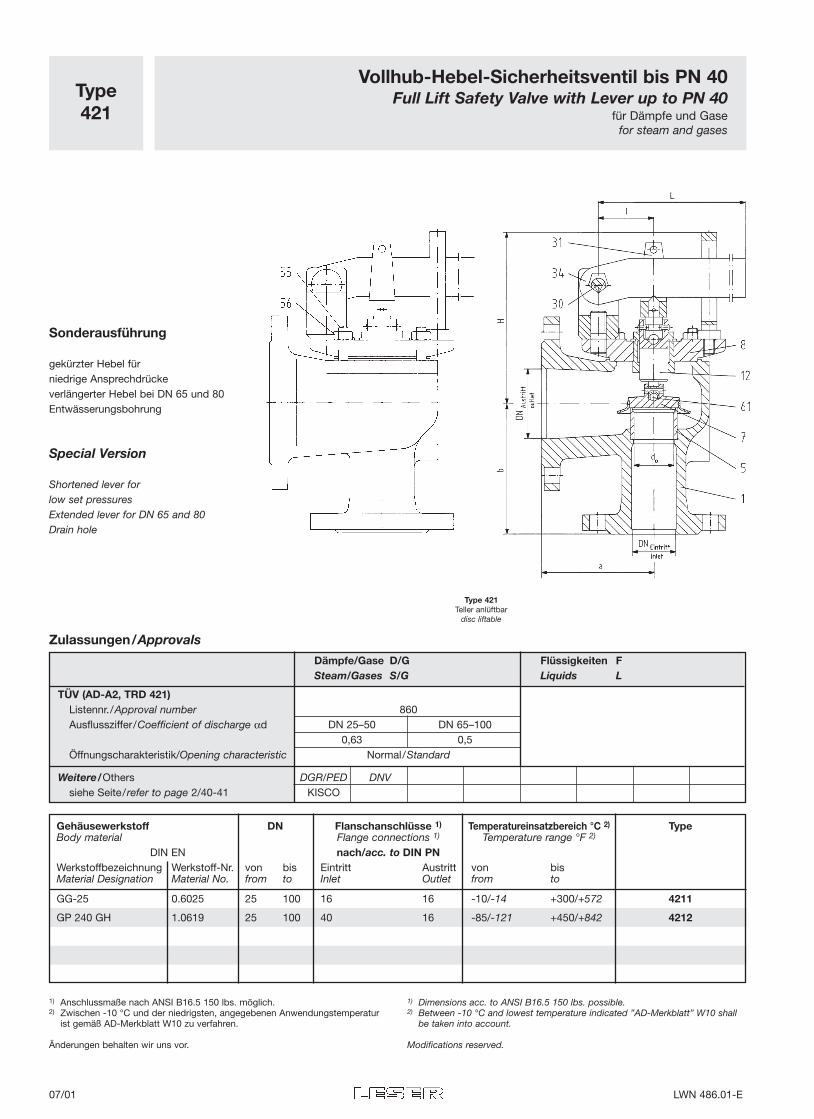
Dämpfe/Gase D/G Flüssigkeiten FSteam/Gases S/G Liquids L
TÜV (AD-A2, TRD 421)Listennr./Approval number 860Ausflussziffer/Coefficient of discharge αd DN 25–50 DN 65–100
0,63 0,5Öffnungscharakteristik/Opening characteristic Normal/Standard
Weitere/Others DGR/PED DNVsiehe Seite/refer to page 2/40-41 KISCO
Gehäusewerkstoff DN Flanschanschlüsse 1) Temperatureinsatzbereich °C 2) TypeBody material Flange connections 1) Temperature range °F 2)
DIN EN nach/acc. to DIN PNWerkstoffbezeichnung Werkstoff-Nr. von bis Eintritt Austritt von bisMaterial Designation Material No. from to Inlet Outlet from to
GG-25 0.6025 25 100 16 16 -10/-14 +300/+572 4211
GP 240 GH 1.0619 25 100 40 16 -85/-121 +450/+842 4212
Type421
Vollhub-Hebel-Sicherheitsventil bis PN 40Full Lift Safety Valve with Lever up to PN 40
für Dämpfe und Gasefor steam and gases
Type 421Teller anlüftbar
disc liftable
Sonderausführung
gekürzter Hebel für niedrige Ansprechdrückeverlängerter Hebel bei DN 65 und 80Entwässerungsbohrung
Special Version
Shortened lever forlow set pressuresExtended lever for DN 65 and 80Drain hole
Zulassungen/Approvals
1) Anschlussmaße nach ANSI B16.5 150 lbs. möglich.2) Zwischen -10 °C und der niedrigsten, angegebenen Anwendungstemperatur
ist gemäß AD-Merkblatt W10 zu verfahren.
Änderungen behalten wir uns vor.
1) Dimensions acc. to ANSI B16.5 150 lbs. possible.2) Between -10 °C and lowest temperature indicated ”AD-Merkblatt” W10 shall
be taken into account.
Modifications reserved.
07/01 LWN 486.01-E
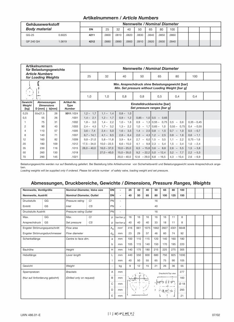
Nennweite, Ventilgröße Nominal Diameter, Valve size DN - 25 32 40 50 65 80 100
Nennweite, Austritt Nominal Diameter, Outlet DN - 40 50 65 80 100 125 150
Druckstufe GG Pressure rating CI PN - 16
Eintritt GS Inlet CS PN - 40
Druckstufe Austritt Pressure rating Outlet PN - 16
Max. GG Max. CI p bar/bar g 16 16 16 16 16 11 8
Ansprechdruck GS Set pressure CS p bar/bar g 40 40 40 33 18 11 8
Engster Strömungsquerschnitt Flow area Ao mm2 416 661 1075 1662 2827 4301 6648
Engster Strömungsdurchmesser Flow diameter do mm 23 29 37 46 60 74 92
Schenkellänge Centre to face dim. a mm 100 110 115 120 140 160 180
b mm 105 115 140 150 170 195 220
Bauhöhe Height H mm 140 175 180 215 225 275 305
Hebellänge Lever length L mm 440 550 600 680 750 825 1030
l mm 40 50 55 65 75 90 105
Gewicht Weight - kg 9 12 15 21 26 36 55
Spannpratzen Brackets A mm 277
(Nur auf Anforderung gebohrt) (Drilled only on request) B mm 160
C mm Ø 18
D mm 293
E mm 21
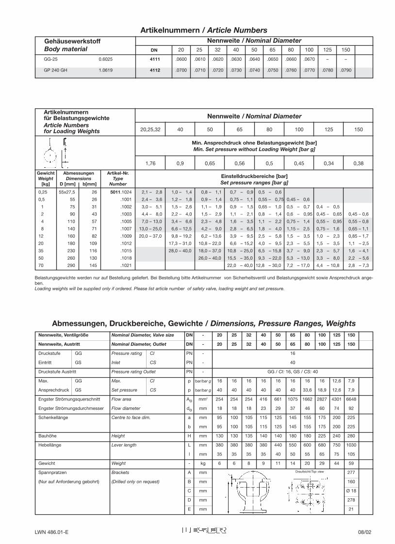
Abmessungen, Druckbereiche, Gewichte / Dimensions, Pressure Ranges, Weights
GehäusewerkstoffBody material 25 32 40 50 65 80 100
Nennweite / Nominal Diameter
Artikelnummern / Article Numbers
GG-25 0.6025 4211 .0800 .0810 .0820 .0830 .0840 .0850 .0860
GP 240 GH 1.0619 4212 .0880 .0890 .0900 .0910 .0920 .0930 .0940
Draufsicht/Top view
0,25 55x27,5 26 5011.1024 1,2 – 1,7 1,1 – 1,4 0,8 – 1,0
0,5 55 26 .1001 1,4 – 2,1 1,2 – 1,7 0,9 – 1,2 0,85 – 1,0 0,5 – 0,65
1 75 31 .1002 1,8 – 3,0 1,4 – 2,2 1,0 – 1,6 0,9 – 1,3 0,55 – 0,75 0,5 – 0,6 0,35 – 0,45
2 90 43 .1003 2,4 – 4,5 1,7 – 3,2 1,3 – 2,2 1,0 – 1,7 0,65 – 1,0 0,55 – 0,75 0,4 – 0,55
4 110 57 .1005 3,6 – 7,4 2,4 – 5,0 1,6 – 3,5 1,4 – 2,5 0,8 – 1,5 0,7 – 1,0 0,5 – 0,7
8 140 71 .1007 6,7 – 14,1 4,1 – 9,5 2,8 – 6,4 2,0 – 4,3 1,2 – 2,5 0,8 – 1,6 0,6 – 1,1
12 160 82 .1009 9,8 – 21,0 5,8 – 11,8 3,9 – 9,4 2,7 – 6,0 1,5 – 3,5 1,1 – 2,2 0,75 – 1,6
20 180 109 .1012 17,5 – 34,0 10,0 – 22,5 6,6 – 15,0 4,1 – 9,8 2,3 – 5,4 1,5 – 3,4 1,0 – 2,4
35 230 116 .1015 28,0 – 40,0 16,0 – 37,0 10,0 – 25,0 6,5 – 15,8 3,6 – 8,8 2,6 – 5,5 1,5 – 3,8
50 260 130 .1018 27,0 – 40,0 15,0 – 35,0 9,2 – 22,2 5,0 – 12,4 3,2 – 7,7 2,2 – 5,3
70 290 145 .1021 20,0 – 40,0 12,6 – 29,0 6,8 – 16,5 4,3 – 10,4 2,6 – 6,9
Belastungsgewichte werden nur auf Bestellung geliefert. Bei Bestellung bitte Artikelnummer von Sicherheitsventil und Belastungsgewicht sowie Ansprechdruck ange-ben.Loading weights will be supplied only if ordered. Please list article number of safety valve, loading weight and set pressure.
Gewicht Abmessungen Artikel-Nr.Weight Dimensions Type
[kg] D [mm] b[mm] Number
Artikelnummernfür BelastungsgewichteArticle Numbersfor Loading Weights
Nennweite / Nominal Diameter
25 32 40 50 65 80 100
Min. Ansprechdruck ohne Belastungsgewicht [bar]Min. Set pressure without Loading Weight [bar g]
1,0 1,0 0,8 0,8 0,5 0,4 0,4
Einstelldruckbereiche [bar]Set pressure ranges [bar g]
DN
LWN 486.01-E 07/02
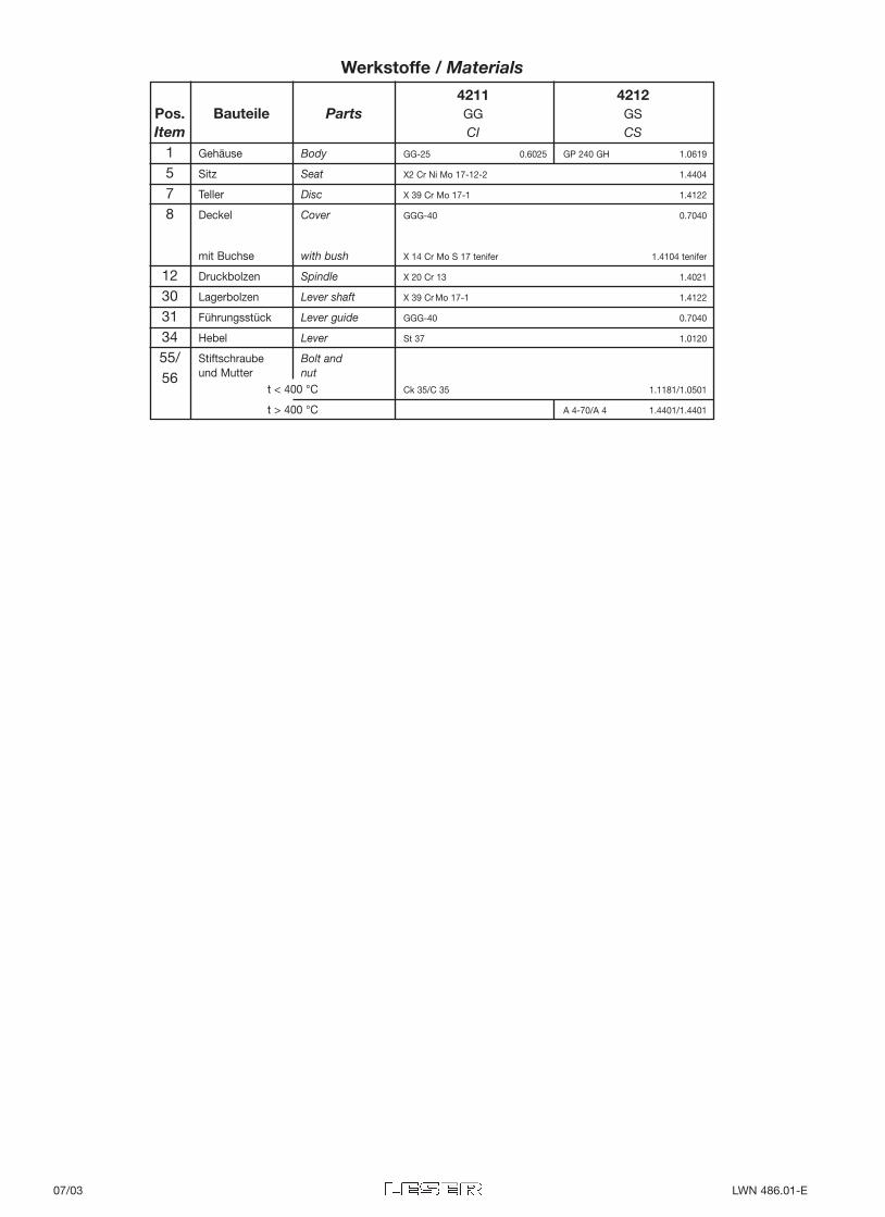
Gehäuse Body GG-25 0.6025 GP 240 GH 1.0619
Sitz Seat X2 Cr Ni Mo 17-12-2 1.4404
Teller Disc X 39 Cr Mo 17-1 1.4122
Deckel Cover GGG-40 0.7040
mit Buchse with bush X 14 Cr Mo S 17 tenifer 1.4104 tenifer
Druckbolzen Spindle X 20 Cr 13 1.4021
Lagerbolzen Lever shaft X 39 Cr Mo 17-1 1.4122
Führungsstück Lever guide GGG-40 0.7040
Hebel Lever St 37 1.0120
Stiftschraube Bolt andund Mutter nut
t < 400 °C Ck 35/C 35 1.1181/1.0501
t > 400 °C A 4-70/A 4 1.4401/1.4401
1578
1230313455/56
4211 4212Pos. Bauteile Parts GG GSItem CI CS
Werkstoffe / Materials
07/03 LWN 486.01-E
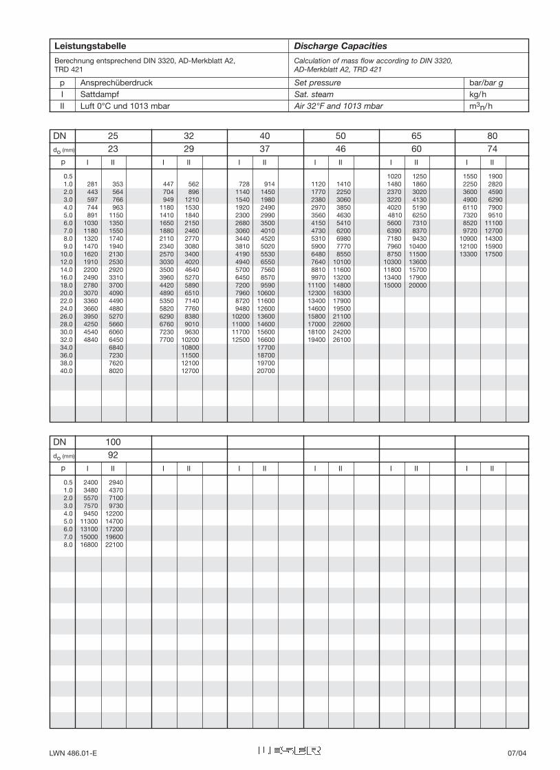
DN 25 32 40 50 65 80do (mm) 23 29 37 46 60 74
I II I II I II I II I II I IIp
0.5 1020 1250 1550 19001.0 281 353 447 562 728 914 1120 1410 1480 1860 2250 28202.0 443 564 704 896 1140 1450 1770 2250 2370 3020 3600 45903.0 597 766 949 1210 1540 1980 2380 3060 3220 4130 4900 62904.0 744 963 1180 1530 1920 2490 2970 3850 4020 5190 6110 79005.0 891 1150 1410 1840 2300 2990 3560 4630 4810 6250 7320 95106.0 1030 1350 1650 2150 2680 3500 4150 5410 5600 7310 8520 111007.0 1180 1550 1880 2460 3060 4010 4730 6200 6390 8370 9720 127008.0 1320 1740 2110 2770 3440 4520 5310 6980 7180 9430 10900 143009.0 1470 1940 2340 3080 3810 5020 5900 7770 7960 10400 12100 15900
10.0 1620 2130 2570 3400 4190 5530 6480 8550 8750 11500 13300 1750012.0 1910 2530 3030 4020 4940 6550 7640 10100 10300 1360014.0 2200 2920 3500 4640 5700 7560 8810 11600 11800 1570016.0 2490 3310 3960 5270 6450 8570 9970 13200 13400 1790018.0 2780 3700 4420 5890 7200 9590 11100 14800 15000 2000020.0 3070 4090 4890 6510 7960 10600 12300 1630022.0 3360 4490 5350 7140 8720 11600 13400 1790024.0 3660 4880 5820 7760 9480 12600 14600 1950026.0 3950 5270 6290 8380 10200 13600 15800 2110028.0 4250 5660 6760 9010 11000 14600 17000 2260030.0 4540 6060 7230 9630 11700 15600 18100 2420032.0 4840 6450 7700 10200 12500 16600 19400 2610034.0 6840 10800 1770036.0 7230 11500 1870038.0 7620 12100 1970040.0 8020 12700 20700
DN 100do (mm) 92
I II I II I II I II I II I IIp
0.5 2400 29401.0 3480 43702.0 5570 71003.0 7570 97304.0 9450 122005.0 11300 147006.0 13100 172007.0 15000 196008.0 16800 22100
p Ansprechüberdruck Set pressure bar/bar gI Sattdampf Sat. steam kg/hII Luft 0°C und 1013 mbar Air 32°F and 1013 mbar m3n/h
Leistungstabelle Discharge Capacities
Berechnung entsprechend DIN 3320, AD-Merkblatt A2, Calculation of mass flow according to DIN 3320,TRD 421 AD-Merkblatt A2, TRD 421
LWN 486.01-E 07/04

Gehäusewerkstoff DN Flanschanschlüsse 1) Temperatureinsatzbereich °C 2) TypeBody material Flange connections 1) Temperature range °F 2)
DIN EN nach/acc. to DIN PN
Werkstoffbezeichnung Werkstoff-Nr. von bis Eintritt Austritt von bisMaterial Designation Material No. from to Inlet Outlet from to
GG-25 0.6025 20 100 16 16 -10/+14 +300/+572 4111
GP 240 GH 1.0619 20 150 40 40 -85/-121 +450/+842 4112
Type411
Normal-Hebel-Sicherheitsventil bis PN 40Safety Relief Valve with Lever up to PN 40
für Dämpfe und Gasefor steam and gases
Type 411Teller anlüftbar
disc liftable
55
56
Sonderausführung
gekürzter Hebel für niedrige AnsprechdrückeEntwässerungsbohrung
Special Version
Shortened lever forlow set pressuresDrain hole
Zulassungen/Approvals
1) Anschlussmaße nach ANSI B16.5 150 lbs. möglich.2) Zwischen -10 °C und der niedrigsten, angegebenen Anwendungstemperatur
ist gemäß AD-Merkblatt W10 zu verfahren.
Änderungen behalten wir uns vor.
1) Dimensions acc. to ANSI B16.5 150 lbs. possible.2) Between -10 °C and lowest temperature indicated ”AD-Merkblatt” W10 shall
be taken into account.
Modifications reserved.
Dämpfe/Gase D/G Flüssigkeiten FSteam/Gases S/G Liquids L
TÜV (AD-A2, TRD 421)Listennr./Approval number 731Ausflussziffer/Coefficient of discharge αd DN 20–50 DN 65–150
0,34 0,28Öffnungscharakteristik/Opening characteristic Normal/Standard
Weitere/Others DGR/PED DNVsiehe Seite/refer to page 2/40-41 KISCO TMBEF
08/01 LWN 486.01-E
0,25 55x27,5 26 5011.1024 2,1 – 2,8 1,0 – 1,4 0,8 – 1,1 0,7 – 0,9 0,5 – 0,6
0,5 55 26 .1001 2,4 – 3,6 1,2 – 1,8 0,9 – 1,4 0,75 – 1,1 0,55 – 0,75 0,45 – 0,6
1 75 31 .1002 3,0 – 5,1 1,5 – 2,6 1,1 – 1,9 0,9 – 1,5 0,65 – 1,0 0,5 – 0,7 0,4 – 0,5
2 90 43 .1003 4,4 – 8,0 2,2 – 4,0 1,5 – 2,9 1,1 – 2,1 0,8 – 1,4 0,6 – 0,95 0,45 – 0,65 0,45 – 0,6
4 110 57 .1005 7,0 – 13,0 3,4 – 6,6 2,3 – 4,8 1,6 – 3,5 1,1 – 2,2 0,75 – 1,4 0,55 – 0,95 0,55 – 0,8
8 140 71 .1007 13,0 – 25,0 6,6 – 12,5 4,2 – 9,0 2,8 – 6,5 1,8 – 4,0 1,15 – 2,5 0,75 – 1,6 0,65 – 1,1
12 160 82 .1009 20,0 – 37,0 9,8 – 19,2 6,2 – 13,6 3,9 – 9,5 2,5 – 5,8 1,5 – 3,5 1,0 – 2,3 0,85 – 1,7
20 180 109 .1012 17,3 – 31,0 10,8 – 22,0 6,6 – 15,2 4,0 – 9,5 2,3 – 5,5 1,5 – 3,5 1,1 – 2,5
35 230 116 .1015 28,0 – 40,0 18,0 – 37,0 10,8 – 25,0 6,5 – 15,8 3,7 – 9,0 2,3 – 5,7 1,6 – 4,1
50 260 130 .1018 26,0 – 40,0 15,5 – 35,0 9,3 – 22,0 5,3 – 13,0 3,3 – 8,0 2,2 – 5,6
70 290 145 .1021 22,0 – 40,0 12,8 – 30,0 7,2 – 17,0 4,4 – 10,8 2,8 – 7,3
Belastungsgewichte werden nur auf Bestellung geliefert. Bei Bestellung bitte Artikelnummer von Sicherheitsventil und Belastungsgewicht sowie Ansprechdruck ange-ben.Loading weights will be supplied only if ordered. Please list article number of safety valve, loading weight and set pressure.
Gewicht Abmessungen Artikel-Nr.Weight Dimensions Type
[kg] D [mm] b[mm] Number
Artikelnummernfür BelastungsgewichteArticle Numbersfor Loading Weights
Nennweite / Nominal Diameter
20,25,32 40 50 65 80 100 125 150
Min. Ansprechdruck ohne Belastungsgewicht [bar]Min. Set pressure without Loading Weight [bar g]
1,76 0,9 0,65 0,56 0,5 0,45 0,34 0,38
Einstelldruckbereiche [bar]Set pressure ranges [bar g]
Nennweite, Ventilgröße Nominal Diameter, Valve size DN - 20 25 32 40 50 65 80 100 125 150
Nennweite, Austritt Nominal Diameter, Outlet DN - 20 25 32 40 50 65 80 100 125 150
Druckstufe GG Pressure rating CI PN - 16
Eintritt GS Inlet CS PN - 40
Druckstufe Austritt Pressure rating Outlet PN - GG / CI: 16, GS / CS: 40
Max. GG Max. CI p bar/bar g 16 16 16 16 16 16 16 16 12,6 7,9
Ansprechdruck GS Set pressure CS p bar/bar g 40 40 40 40 40 40 33,6 18,9 12,6 7,9
Engster Strömungsquerschnitt Flow area Ao mm2 254 254 254 416 661 1075 1662 2827 4301 6648
Engster Strömungsdurchmesser Flow diameter do mm 18 18 18 23 29 37 46 60 74 92
Schenkellänge Centre to face dim. a mm 95 100 105 115 125 145 155 175 200 225
b mm 95 100 105 115 125 145 155 175 200 225
Bauhöhe Height H mm 130 130 135 140 140 180 180 225 240 280
Hebellänge Lever length L mm 380 380 380 380 440 550 600 680 750 1030
l mm 35 35 35 35 40 50 55 65 75 105
Gewicht Weight - kg 6 6 8 9 11 14 20 29 44 59
Spannpratzen Brackets A mm 277
(Nur auf Anforderung gebohrt) (Drilled only on request) B mm 160
C mm Ø 18
D mm 278
E mm 21
Abmessungen, Druckbereiche, Gewichte / Dimensions, Pressure Ranges, Weights
GehäusewerkstoffBody material 20 25 32 40 50 65 80 100 125 150
Nennweite / Nominal Diameter
Artikelnummern / Article Numbers
GG-25 0.6025 4111 .0600 .0610 .0620 .0630 .0640 .0650 .0660 .0670 – –
GP 240 GH 1.0619 4112 .0700 .0710 .0720 .0730 .0740 .0750 .0760 .0770 .0780 .0790
Draufsicht/Top view
DN
LWN 486.01-E 08/02
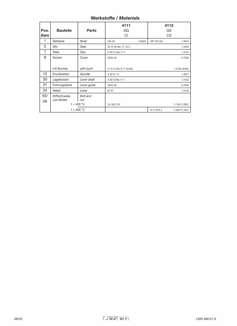
Gehäuse Body GG-25 0.6025 GP 240 GH 1.0619
Sitz Seat X2 Cr Ni Mo 17-12-2 1.4404
Teller Disc X 39 Cr Mo 17-1 1.4122
Deckel Cover GGG-40 0.7040
mit Buchse with bush X 14 Cr Mo S 17 tenifer 1.4104 tenifer
Druckbolzen Spindle X 20 Cr 13 1.4021
Lagerbolzen Lever shaft X 39 Cr Mo 17-1 1.4122
Führungsstück Lever guide GGG-40 0.7040
Hebel Lever St 37 1.0120
Stiftschraube Bolt andund Mutter nut
t < 400 °C Ck 35/C 35 1.1181/1.0501
t > 400 °C A 4-70/A 4 1.4401/1.4401
1578
1230313455/56
4111 4112Pos. Bauteile Parts GG GSItem CI CS
Werkstoffe / Materials
08/03 LWN 486.01-E
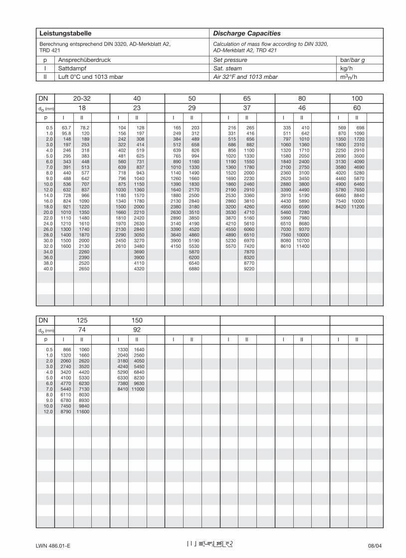
p Ansprechüberdruck Set pressure bar/bar gI Sattdampf Sat. steam kg/hII Luft 0°C und 1013 mbar Air 32°F and 1013 mbar m3n/h
DN 20-32 40 50 65 80 100do (mm) 18 23 29 37 46 60
I II I II I II I II I II I IIp
0.5 63.7 78.2 104 128 165 203 216 265 335 410 569 6981.0 95.8 120 156 197 249 312 331 416 511 642 870 10902.0 148 189 242 308 384 489 515 656 797 1010 1350 17203.0 197 253 322 414 512 658 686 882 1060 1360 1800 23104.0 246 318 402 519 639 826 856 1100 1320 1710 2250 29105.0 295 383 481 625 765 994 1020 1330 1580 2050 2690 35006.0 343 448 560 731 890 1160 1190 1550 1840 2400 3130 40907.0 391 513 639 837 1010 1330 1360 1780 2100 2750 3580 46908.0 440 577 718 943 1140 1490 1520 2000 2360 3100 4020 52809.0 488 642 796 1040 1260 1660 1690 2230 2620 3450 4460 5870
10.0 536 707 875 1150 1390 1830 1860 2460 2880 3800 4900 646012.0 632 837 1030 1360 1640 2170 2190 2910 3390 4490 5780 765014.0 728 966 1180 1570 1880 2500 2530 3360 3910 5190 6660 884016.0 824 1090 1340 1780 2130 2840 2860 3810 4430 5890 7540 1000018.0 921 1220 1500 2000 2380 3180 3200 4260 4950 6590 8420 1120020.0 1010 1350 1660 2210 2630 3510 3530 4710 5460 728022.0 1110 1480 1810 2420 2890 3850 3870 5160 5990 798024.0 1210 1610 1970 2630 3140 4190 4210 5610 6510 868026.0 1300 1740 2130 2840 3390 4520 4550 6060 7030 937028.0 1400 1870 2290 3050 3640 4860 4890 6510 7560 1000030.0 1500 2000 2450 3270 3900 5190 5230 6970 8080 1070032.0 1600 2130 2610 3480 4150 5530 5570 7420 8610 1140034.0 2260 3690 5870 787036.0 2390 3900 6200 832038.0 2520 4110 6540 877040.0 2650 4320 6880 9220
DN 125 150do (mm) 74 92
I II I II I II I II I II I IIp
0.5 866 1060 1330 16401.0 1320 1660 2040 25602.0 2060 2620 3180 40503.0 2740 3520 4240 54504.0 3420 4420 5290 68405.0 4100 5330 6330 82306.0 4770 6230 7380 96307.0 5440 7130 8410 110008.0 6110 80309.0 6780 8930
10.0 7450 984012.0 8790 11600
Leistungstabelle Discharge Capacities
Berechnung entsprechend DIN 3320, AD-Merkblatt A2, Calculation of mass flow according to DIN 3320,TRD 421 AD-Merkblatt A2, TRD 421
LWN 486.01-E 08/04
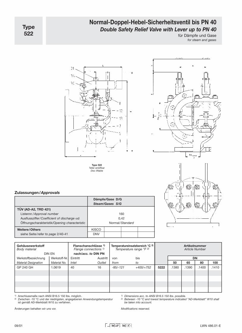
Type522
Normal-Doppel-Hebel-Sicherheitsventil bis PN 40Double Safety Relief Valve with Lever up to PN 40
für Dämpfe und Gasefor steam and gases
Type 522Teller anlüftbar
Disc liftable
Gehäusewerkstoff Flanschanschlüsse 1) Temperatureinsatzbereich °C 2) ArtikelnummerBody material Flange connections 1) Temperature range °F 2) Article Number
DIN EN nach/acc. to DIN PNWerkstoffbezeichnung Werkstoff-Nr. Eintritt Austritt von bis DNMaterial Designation Material No. Inlet Outlet from to 50 65 80 100
GP 240 GH 1.0619 40 16 -85/-121 +400/+752 5222 .1380 .1390 .1400 .1410
Zulassungen/Approvals
Dämpfe/Gase D/GSteam/Gases S/G
TÜV (AD-A2, TRD 421)Listennr./Approval number 160Ausflussziffer/Coefficient of discharge αd 0,42Öffnungscharakteristik/Opening characteristic Normal/Standard
Weitere/Others KISCOsiehe Seite/refer to page 2/40-41 DNV
1) Anschlussmaße nach ANSI B16.5 150 lbs. möglich.2) Zwischen -10 °C und der niedrigsten, angegebenen Anwendungstemperatur
ist gemäß AD-Merkblatt W10 zu verfahren.
Änderungen behalten wir uns vor.
1) Dimensions acc. to ANSI B16.5 150 lbs. possible.2) Between -10 °C and lowest temperature indicated ”AD-Merkblatt” W10 shall
be taken into account.
Modifications reserved.
09/01 LWN 486.01-E
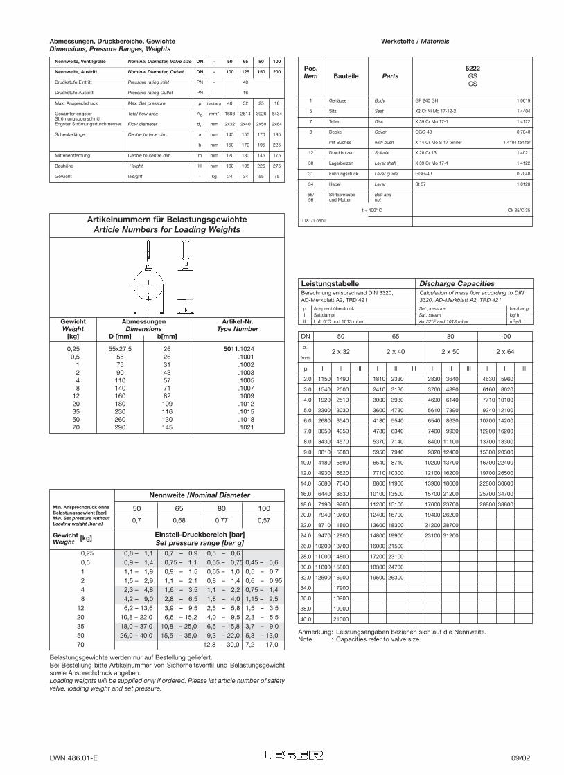
p Ansprechüberdruck Set pressure bar/bar gI Sattdampf Sat. steam kg/hII Luft 0°C und 1013 mbar Air 32°F and 1013 mbar m3n/h
I II III I II III I II III I II III
2.0 1150 1490 1810 2330 2830 3640 4630 5960
3.0 1540 2000 2410 3130 3760 4890 6160 8020
4.0 1920 2510 3000 3930 4690 6140 7710 10100
5.0 2300 3030 3600 4730 5610 7390 9240 12100
6.0 2680 3540 4180 5540 6540 8630 10700 14200
7.0 3050 4050 4780 6340 7460 9930 12200 16200
8.0 3430 4570 5370 7140 8400 11100 13700 18300
9.0 3810 5080 5950 7940 9320 12400 15300 20300
10.0 4180 5590 6540 8710 10200 13700 16700 22400
12.0 4930 6620 7710 10300 12100 16200 19700 26500
14.0 5680 7640 8860 11900 13900 18600 22800 30600
16.0 6440 8630 10100 13500 15700 21200 25700 34700
18.0 7190 9700 11200 15100 17600 23700 28800 38800
20.0 7940 10700 12400 16700 19400 26200
22.0 8710 11800 13600 18300 21200 28700
24.0 9470 12800 14800 19900 23100 31200
26.0 10200 13700 16000 21500
28.0 11000 14800 17200 23100
30.0 11800 15800 18300 24700
32.0 12500 16900 19500 26300
34.0 17900
36.0 18900
38.0 19900
40.0 21000
p
2 x 32 2 x 40 2 x 50 2 x 64
DN 50 65 80 100
do
(mm)
Nennweite, Ventilgröße Nominal Diameter, Valve size DN - 50 65 80 100
Nennweite, Austritt Nominal Diameter, Outlet DN - 100 125 150 200
Druckstufe Eintritt Pressure rating Inlet PN - 40
Druckstufe Austritt Pressure rating Outlet PN - 16
Max. Ansprechdruck Max. Set pressure p bar/bar g 40 32 25 18
Total flow area Ao mm2 1608 2514 3926 6434
Flow diameter do mm 2x32 2x40 2x50 2x64
Schenkellänge Centre to face dim. a mm 145 155 170 195
b mm 150 170 195 225
Mittenentfernung Centre to centre dim. m mm 120 130 145 175
Bauhöhe Height H mm 160 195 225 275
Gewicht Weight - kg 24 34 55 75
Abmessungen, Druckbereiche, GewichteDimensions, Pressure Ranges, Weights
1 Gehäuse Body GP 240 GH 1.0619
5 Sitz Seat X2 Cr Ni Mo 17-12-2 1.4404
7 Teller Disc X 39 Cr Mo 17-1 1.4122
8 Deckel Cover GGG-40 0.7040
mit Buchse with bush X 14 Cr Mo S 17 tenifer 1.4104 tenifer
12 Druckbolzen Spindle X 20 Cr 13 1.4021
30 Lagerbolzen Lever shaft X 39 Cr Mo 17-1 1.4122
31 Führungsstück Lever guide GGG-40 0.7040
34 Hebel Lever St 37 1.0120
55/ Stiftschraube Bolt and56 und Mutter nut
t < 400° C Ck 35/C 35
1.1181/1.0501
Pos. 5222Item Bauteile Parts GS
CS
Werkstoffe / Materials
Einstell-Druckbereich [bar]Set pressure range [bar g]
0,25 0,8 – 1,1 0,7 – 0,9 0,5 – 0,60,5 0,9 – 1,4 0,75 – 1,1 0,55 – 0,75 0,45 – 0,61 1,1 – 1,9 0,9 – 1,5 0,65 – 1,0 0,5 – 0,72 1,5 – 2,9 1,1 – 2,1 0,8 – 1,4 0,6 – 0,954 2,3 – 4,8 1,6 – 3,5 1,1 – 2,2 0,75 – 1,48 4,2 – 9,0 2,8 – 6,5 1,8 – 4,0 1,15 – 2,5
12 6,2 – 13,6 3,9 – 9,5 2,5 – 5,8 1,5 – 3,520 10,8 – 22,0 6,6 – 15,2 4,0 – 9,5 2,3 – 5,535 18,0 – 37,0 10,8 – 25,0 6,5 – 15,8 3,7 – 9,050 26,0 – 40,0 15,5 – 35,0 9,3 – 22,0 5,3 – 13,070 12,8 – 30,0 7,2 – 17,0
Min. Ansprechdruck ohneBelastungsgewicht [bar]Min. Set pressure withoutLoading weight [bar g]
Gewicht [kg]Weight
Nennweite /Nominal Diameter
50 65 80 100
0,7 0,68 0,77 0,57
Belastungsgewichte werden nur auf Bestellung geliefert. Bei Bestellung bitte Artikelnummer von Sicherheitsventil und Belastungsgewichtsowie Ansprechdruck angeben.Loading weights will be supplied only if ordered. Please list article number of safetyvalve, loading weight and set pressure.
0,25 55x27,5 26 5011.10240,5 55 26 .1001
1 75 31 .10022 90 43 .10034 110 57 .10058 140 71 .1007
12 160 82 .100920 180 109 .101235 230 116 .101550 260 130 .101870 290 145 .1021
Gewicht Abmessungen Artikel-Nr.Weight Dimensions Type Number
[kg] D [mm] b[mm]
Artikelnummern für BelastungsgewichteArticle Numbers for Loading Weights
Gesamter engsterStrömungsquerschnittEngster Strömungsdurchmesser
LeistungstabelleBerechnung entsprechend DIN 3320, AD-Merkblatt A2, TRD 421
Discharge CapacitiesCalculation of mass flow according to DIN3320, AD-Merkblatt A2, TRD 421
Anmerkung: Leistungsangaben beziehen sich auf die Nennweite.Note : Capacities refer to valve size.
LWN 486.01-E 09/02
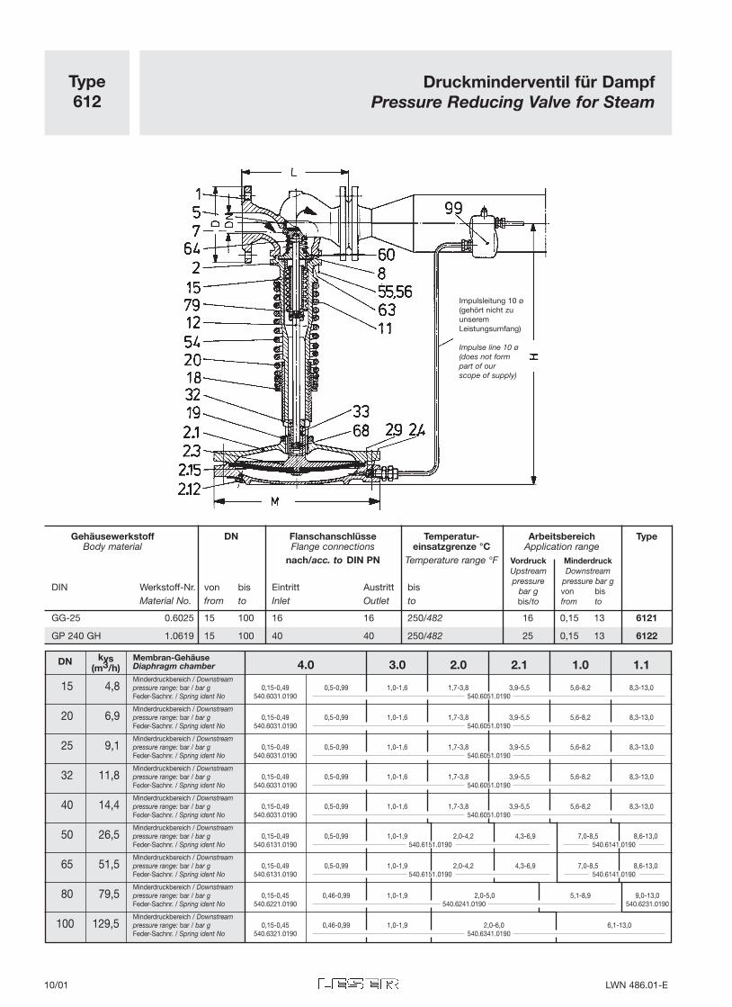
Type612
Druckminderventil für Dampf Pressure Reducing Valve for Steam
VordruckUpstreampressure
bar gbis/to
MinderdruckDownstream
pressure bar gvon bisfrom to
Impulsleitung 10 ø(gehört nicht zuunseremLeistungsumfang)
Impulse line 10 ø(does not formpart of our scope of supply)
Gehäusewerkstoff DN Flanschanschlüsse Temperatur- Arbeitsbereich TypeBody material Flange connections einsatzgrenze °C Application range
nach/acc. to DIN PN Temperature range °F
DIN Werkstoff-Nr. von bis Eintritt Austritt bisMaterial No. from to Inlet Outlet to
GG-25 0.6025 15 100 16 16 250/482 16 0,15 13 6121
GP 240 GH 1.0619 15 100 40 40 250/482 25 0,15 13 6122
kvs Membran-GehäuseDN(m3/h) Diaphragm chamber 4.0 3.0 2.0 2.1 1.0 1.1
Minderdruckbereich / Downstream15 4,8 pressure range: bar / bar g 0,15-0,49 0,5-0,99 1,0-1,6 1,7-3,8 3,9-5,5 5,6-8,2 8,3-13,0
Feder-Sachnr. / Spring ident No 540.6031.0190 540.6051.0190
Minderdruckbereich / Downstream20 6,9 pressure range: bar / bar g 0,15-0,49 0,5-0,99 1,0-1,6 1,7-3,8 3,9-5,5 5,6-8,2 8,3-13,0
Feder-Sachnr. / Spring ident No 540.6031.0190 540.6051.0190
Minderdruckbereich / Downstream25 9,1 pressure range: bar / bar g 0,15-0,49 0,5-0,99 1,0-1,6 1,7-3,8 3,9-5,5 5,6-8,2 8,3-13,0
Feder-Sachnr. / Spring ident No 540.6031.0190 540.6051.0190
Minderdruckbereich / Downstream32 11,8 pressure range: bar / bar g 0,15-0,49 0,5-0,99 1,0-1,6 1,7-3,8 3,9-5,5 5,6-8,2 8,3-13,0
Feder-Sachnr. / Spring ident No 540.6031.0190 540.6051.0190
Minderdruckbereich / Downstream40 14,4 pressure range: bar / bar g 0,15-0,49 0,5-0,99 1,0-1,6 1,7-3,8 3,9-5,5 5,6-8,2 8,3-13,0
Feder-Sachnr. / Spring ident No 540.6031.0190 540.6051.0190
Minderdruckbereich / Downstream50 26,5 pressure range: bar / bar g 0,15-0,49 0,5-0,99 1,0-1,9 2,0-4,2 4,3-6,9 7,0-8,5 8,6-13,0
Feder-Sachnr. / Spring ident No 540.6131.0190 540.6151.0190 540.6141.0190
Minderdruckbereich / Downstream65 51,5 pressure range: bar / bar g 0,15-0,49 0,5-0,99 1,0-1,9 2,0-4,2 4,3-6,9 7,0-8,5 8,6-13,0
Feder-Sachnr. / Spring ident No 540.6131.0190 540.6151.0190 540.6141.0190
Minderdruckbereich / Downstream80 79,5 pressure range: bar / bar g 0,15-0,45 0,46-0,99 1,0-1,9 2,0-5,0 5,1-8,9 9,0-13,0
Feder-Sachnr. / Spring ident No 540.6221.0190 540.6241.0190 540.6231.0190
Minderdruckbereich / Downstream100 129,5 pressure range: bar / bar g 0,15-0,45 0,46-0,99 1,0-1,9 2,0-6,0 6,1-13,0
Feder-Sachnr. / Spring ident No 540.6321.0190 540.6341.0190
10/01 LWN 486.01-E
Nennweite, Ventilgröße Nominal Diameter, Valve size DN - 15 20 25 32 40 50 65 80 100
Nennweite, Austritt Nominal Diameter, Outlet DN - 15 20 25 32 40 50 65 80 100
Druckstufe GG Pressure rating, CI PN - 16
Eintritt GS SInlet CS PN - 40
Druckstufe Austritt Pressure rating Outlet PN - GG /CI: 16, GS/CS: 40
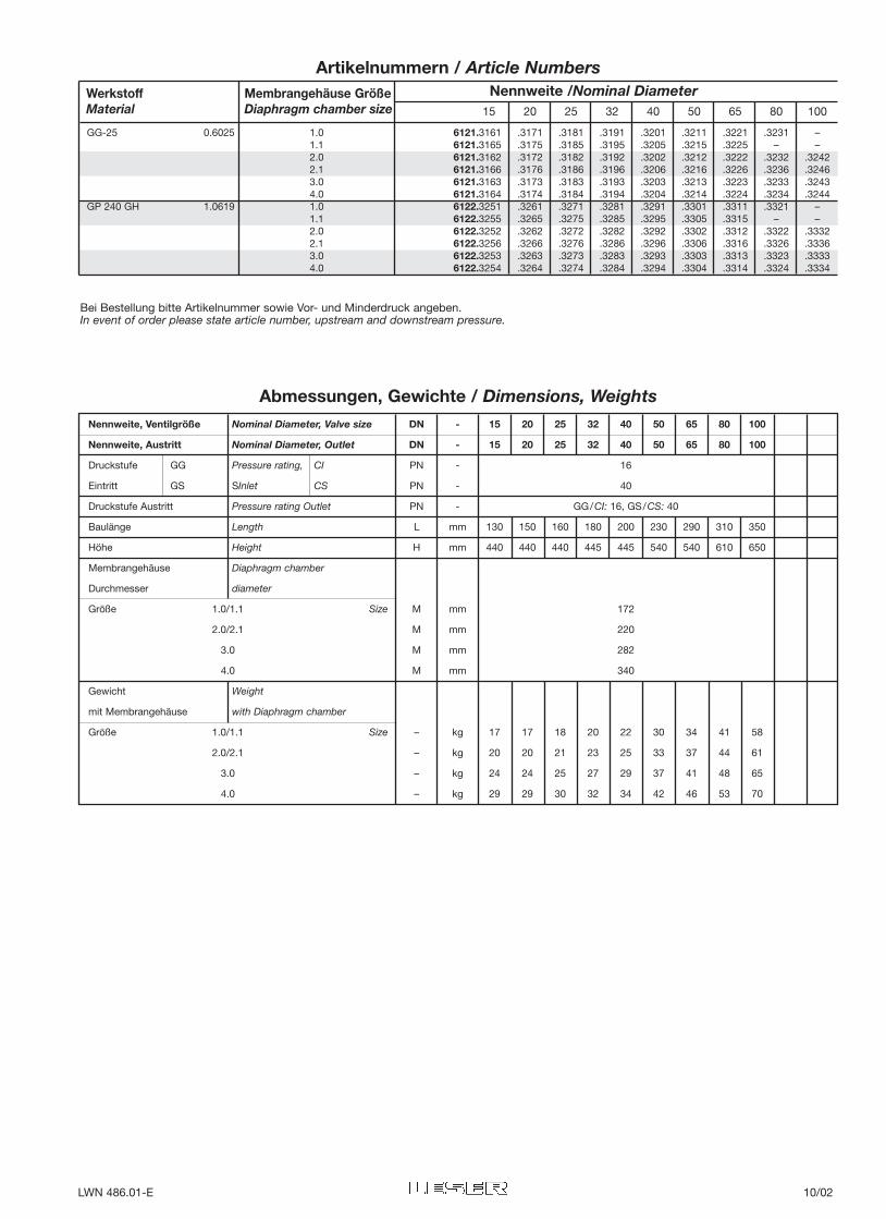
Baulänge Length L mm 130 150 160 180 200 230 290 310 350
Höhe Height H mm 440 440 440 445 445 540 540 610 650
Membrangehäuse Diaphragm chamber
Durchmesser diameter
Größe 1.0/1.1 Size M mm 172
2.0/2.1 M mm 220
3.0 M mm 282
4.0 M mm 340
Gewicht Weight
mit Membrangehäuse with Diaphragm chamber
Größe 1.0/1.1 Size – kg 17 17 18 20 22 30 34 41 58
2.0/2.1 – kg 20 20 21 23 25 33 37 44 61
3.0 – kg 24 24 25 27 29 37 41 48 65
4.0 – kg 29 29 30 32 34 42 46 53 70
Abmessungen, Gewichte / Dimensions, Weights
Werkstoff Membrangehäuse GrößeMaterial Diaphragm chamber size 15 20 25 32 40 50 65 80 100
Nennweite /Nominal Diameter
Artikelnummern / Article Numbers
Bei Bestellung bitte Artikelnummer sowie Vor- und Minderdruck angeben.In event of order please state article number, upstream and downstream pressure.
GG-25 0.6025 1.0 6121.3161 .3171 .3181 .3191 .3201 .3211 .3221 .3231 –1.1 6121.3165 .3175 .3185 .3195 .3205 .3215 .3225 – –2.0 6121.3162 .3172 .3182 .3192 .3202 .3212 .3222 .3232 .32422.1 6121.3166 .3176 .3186 .3196 .3206 .3216 .3226 .3236 .32463.0 6121.3163 .3173 .3183 .3193 .3203 .3213 .3223 .3233 .32434.0 6121.3164 .3174 .3184 .3194 .3204 .3214 .3224 .3234 .3244
GP 240 GH 1.0619 1.0 6122.3251 .3261 .3271 .3281 .3291 .3301 .3311 .3321 –1.1 6122.3255 .3265 .3275 .3285 .3295 .3305 .3315 – –2.0 6122.3252 .3262 .3272 .3282 .3292 .3302 .3312 .3322 .33322.1 6122.3256 .3266 .3276 .3286 .3296 .3306 .3316 .3326 .33363.0 6122.3253 .3263 .3273 .3283 .3293 .3303 .3313 .3323 .33334.0 6122.3254 .3264 .3274 .3284 .3294 .3304 .3314 .3324 .3334
LWN 486.01-E 10/02
– 180 – 260 – 420 – 650 – 910 – 1650
– 210 – 310 – 500 – 780 – 1000 – 1950
– 240 – 360 – 560 – 880 – 1230 – 2300
460 300 800 440 1250 700 – 1100 – 1550 – 2800
580 370 1000 560 1550 870 – 1380 – 1980 – 3500
700 450 1200 680 1850 1040 – 1650 – 2400 – 4200
910 590 1600 880 2500 1400 – 2200 – 3100 – 5600
1160 750 2000 1120 3050 1750 – 2800 – 3900 – 7000
1390 880 2400 1310 3600 2100 – 3300 – 4600 – 8300
1600 1020 2700 1540 4300 2400 – 3800 – 5300 – 9800
2000 1300 3400 1900 5400 3000 – 4800 – 6800 – 12000
2500 1600 4200 2400 6500 3700 – 5800 – 8200 – 14900
3000 1950 5100 2900 8000 4700 – 7200 – 10000 – 18400
3600 2400 6100 3400 9500 5500 – 8600 – 12200 – 22000
4100 2700 7100 4000 11000 6200 – 9900 – 14200 – 25000
4600 2900 7800 4400 12000 6900 – 10900 – 15500 – 28000
5100 3300 8500 5000 13500 7800 – 12000 – 17000 – 31000
6100 4000 10500 6000 16300 9200 – 14500 – 21000 – 37000
7200 4700 12600 7000 19000 11000 – 17000 – 24500 – 44000
8300 5500 14600 8100 22000 12800 – 20000 – 28000 – –
9500 6200 16600 9200 25000 14600 – 23000 – 32000 – –
10800 7000 18600 10300 28000 16500 – 26000 – 36000 – –
12200 7800 21000 11700 32000 18500 – 29000 – 40000 – –
13700 8700 23500 13200 36000 21000 – 33000 – 46000 – –
14500 9200 25500 14200 38000 23000 – 35000 – 50000 – –
0,15 – 10 – 17 – 27 – 40 – 83 – 120
0,2 – 11 – 19 – 31 – 46 – 99 – 145
0,3 – 13 – 23 – 35 – 55 – 112 – 165
0,5 51 16 68 28 90 46 118 70 186 140 300 200
0,75 63 20 84 35 112 57 146 85 230 175 360 250
1 75 25 100 42 133 68 175 100 280 210 430 300
1,5 100 32 133 55 175 90 240 140 360 280 590 400
2 126 40 170 70 230 115 290 170 450 350 730 520
2,5 150 47 200 84 260 135 350 200 550 400 880 600
3 175 55 240 99 310 155 400 240 640 480 1010 700
4 220 70 290 123 390 195 510 300 800 600 1300 890
5 260 85 350 150 480 245 620 360 1000 740 1600 1080
6 330 104 440 185 580 300 760 450 1220 900 1930 1340
7 400 122 520 225 700 350 910 540 1430 1100 2300 1600
8 450 140 600 250 800 400 1040 600 1670 1250 2700 1800
9 500 160 670 280 880 450 1180 680 1800 1380 2900 2000
10 560 180 750 320 980 500 1300 750 2000 1500 3200 2300
12 680 220 900 380 1180 610 1540 900 2500 1850 4000 2700
14 800 260 1050 450 1400 720 1850 1050 2900 2300 4700 3100
16 920 300 1230 520 1630 830 2150 1230 3400 2600 5500 3600
18 1040 340 1400 590 1860 940 2450 1400 3800 2900 6200 4200
20 1170 380 1540 670 2100 1050 2700 1580 4200 3300 7000 4800
22 1330 425 1780 750 2350 1180 3050 1780 4900 3700 7800 5300
24 1500 475 2000 840 2600 1320 3400 2000 5400 4100 8700 6000
25 1600 510 2150 900 2800 1400 3600 2150 5700 4400 9200 6500
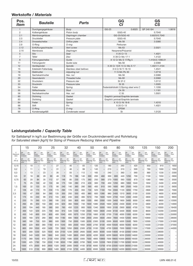
1 Durchgangsgehäuse Body GG-25 0.6025 GP 240 GH 1.06192 Kolbengehäuse Piston body GGG-40 0.70402.1 Membrangehäuse Diaphragm chamber GG-25/GGG-40 0.6025/0.70402.3 Druckteller Pressure plate GGG-40 0.70402.4 Drosselscheibe Orifice plate Ms 58 2.03802.9 O-Ring O-ring Perbunan2.12 Entlüftungsschraube Vent screw Ms 63 2.03212.15 Membrane Diaphragm Neoprene/Polyamid5 Sitz Seat X 20 Cr 13 1.40217 Teller Disc X 39 Cr Mo 17-1 1.41228 Führungsscheibe Guide X 12 Cr Mo S 17/Rg 5 1.4104/2.1096.01
11 Führungsrohr Guide tube Ms 58 2.038012 Ventilspindel Spindle X 20 Cr 13/X 14 Cr Mo S 17 1.4021/1.410415 Edelstahl-Faltenbalg Stainless steel bellows X 6 Cr Ni Ti 18-10 1.454118 Stellmutter Adjusting nut 11 S Mn Pb 30 1.071819 Sechskantmutter Hex. nut Ms 58 2.038020 Gewinderohr Threaded tube Ms 60 2.036032 Druckstern Pressure star St 37-2 1.011233 Druckrohr Pressure tube St 35 1.030554 Feder Spring Federstahldraht C/Spring steel wire C 1.120055 Stiftschraube Stud Ck 35 1.118156 Sechskantmutter Hex. nut C 35 1.050160 Dichtring Gasket Graphit-Laminat/Graphite laminate63 Dichtring Gasket Graphit-Laminat/Graphite laminate64 Feder Spring X 10 Cr Ni 18-8 1.431068 Stift Pin X 20 Cr 13 1.402179 O-Ring O-ring EPDM99 Kondensatgefäß Condensate vessel St 1.0120
15 20 25 32 40 50 65 80 100 125 150 200
Pos. Bauteile Parts GG GSItem CI CS
Leistungstabelle / Capacity Tablefür Sattdampf in kg/h zur Bestimmung der Größe von Druckminderventil und Rohrleitungfor Saturated steam [kg/h] for Sizing of Pressure Reducing Valve and Pipeline
Werkstoffe / Materials
DN DN DN DN DN DN DN DN DN DN DN DNDruck- Rohr Druck- Rohr Druck- Rohr Druck- Rohr Druck- Rohr Druck- Rohrminderer minderer minderer minderer minderer minderer
DN DN DN DN DN DN DN DN DN DN DN DNReducing Pipe Reducing Pipe Reducing Pipe Reducing Pipe Reducing Pipe Reducing Pipevalve valve valve valve valve valve
PÜberdruck
[bar]
P[bar g]
10/03 LWN 486.01-E
Type612
Eigenschaften und Wirkungsweise des Druckminderventils Features and Functioning of Pressure Reducing Valve
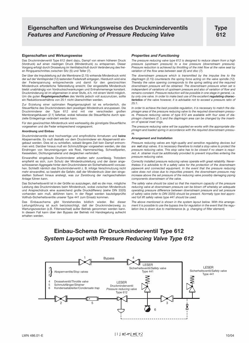
Eigenschaften und WirkungsweiseDas Druckminderventil Type 612 dient dazu, Dampf von einem höheren Druck(Vordruck) auf einen niedrigen Druck (Minderdruck) zu entspannen. DieserVorgang erfolgt durch Drosselung im Ventilabschluß durch Veränderung des frei-en Ringquerschnittes zwischen Sitz (5) und Teller (7).
Der über die Impulsleitung auf die Membrane (2.15) wirkende Minderdruck wirktder auf der Ventilspindel (12) lastenden Federkraft entgegen. Hierdurch wird eineder Federspannung entsprechende und damit für den gewünschtenMinderdruck erforderliche Tellerstellung erreicht. Der eingestellte Minderdruckbleibt unabhängig von Vordruckschwankungen und Entnahmemenge konstant.Druckminderung ist im allgemeinen in einer Stufe, d.h. mit einem Ventil möglich.Um die guten Regeleigenschaften des Ventils jedoch voll auszunutzen, sollteein Reduktionsverhältnis von 25:1 nicht überschritten werden.
Zur Erzielung einer optimalen Regelgenauigkeit ist es erforderlich, dieSteuerfläche des Druckminderers dem jeweiligen Minderdruck anzupassen. DieDruckminderer der Type 612 sind mit vier verschieden großenMembrangehäusen (2.1) lieferbar, wobei teilweise die Steuerfläche durch spe-zielle Einlegeringe verändert werden kann.
Für den gewünschten Minderdruck wird werksseitig die günstigste Steuerflächevorgesehen und die Feder entsprechend vorgespannt.
Anordnung und Einbau
Druckminderventile sind hochwertige und empfindliche Armaturen und keineAbsperrventile. Es muß deshalb vor dem Druckminderer ein Absperrventil ein-gebaut werden. Dies ist zu schließen, sobald längere Zeit kein Dampf entnom-men wird. Darüber hinaus muß ein Schmutzfänger vorgesehen werden, der dasEindringen von Verunreinigungen wie Rost, Hammerschlag, Schweißperlen,Kesselstein, Dichtungsmaterial und dergleichen verhindert.
Einwandfrei eingebaute Druckminderer arbeiten sehr zuverlässig. Trotzdemempfiehlt es sich, zum Schutz der Minderdruckleitung und der daran ange-schlossenen Aggregate hinter dem Druckminderer ein Sicherheitsventil vorzuse-hen. Schließt nämlich das Druckminderventil z. B. infolge Verschmutzung nichtmehr einwandfrei, so besteht die Gefahr, daß der Minderdruck über den einge-stellten Sollwert hinaus ansteigt, was zur Zerstörung der nachgeschaltetenAnlage führen kann.
Das Sicherheitsventil ist in der Größe so auszulegen, daß es die max. möglicheLeistung des Druckminderers beim Minderdruck, wobei zwischen Minderdruckund Ansprechdruck eine ausreichend große Druckdifferenz (siehe DIN 3320)vorhanden sein muß, abführen kann. In der Regel werden bauteilgeprüfteVollhub-Sicherheitsventile unserer Type 441 zum Einsatz kommen.
Das Einbauschema gibt Vorstehendes bildlich wieder. Bei dieserLeitungsführung ist auch berücksichtigt, daß der Druckminderzweig zuWartungszwecken (z.B. Filterwechsel) außer Betrieb genommen werden kann.In diesem Fall kann über den Bypass der Betrieb mit Handregelung aufrechterhalten werden.
Properties and FunctioningThe pressure reducing valve type 612 is designed to reduce steam from a highpressure (upstream pressure) to a low pressure (downstream pressure).Pressure reduction is achieved by throttling of the inlet flow at the valve seat byvariation of the flow area between seat (5) and disc (7).
The downstream pressure which is transmitted by the impulse line to thediaphragm (2.15) counteracts the spring force acting on the valve spindle (12).Thereby the valve opening corresponds to the spring setting and the requireddownstream pressure will be obtained. The downstream pressure when set isindependent of variations of upstream pressure and also of variation of flow andremains constant. Pressure reduction will be possible in one stage in general, i.e.by only one valve. In order to make best use of the excellent regulating charac-teristics of the valve however, it is advisable not to exceed a pressure ratio of25:1.
In order to achieve the best possible regulation, it is necessary to match the dia-phragm area of the pressure reducing valve to the required downstream pressu-re. Pressure reducing valves of type 612 are available with four sizes of dia-phragm chambers (2.1) and the diaphragm area can be changed by the inserti-on of special inset rings.
The pressure reducing valve will be supplied ex-works with the appropriate dia-phragm and loaded spring in accordance with the required downstream pressu-re.
Arrangement and Installation
Pressure reducing valves are high-quality and sensitive regulating devices butare not stop valves. It is necessary therefore to install a stop valve to protect thepressure reducing valve. This stop valve has to be closed if no steam is requi-red. A strainer must be additionally provided to prevent impurities entering thepressure reducing valve.
Correctly installed pressure reducing valves operate with great reliability. Never-theless it is advisible to fit a safety valve for the protection of the downstreampipework and connected equipment. In the event that the pressure reducingvalve does not close due to impurities present, the downstream pressure mayincrease above the set pressure of the reducing valve possibly damaging pipingcomponents downstream of the valve.
The safety valve should be sized so that the maximum capacity of the pressurereducing valve at downstream pressure can be blown off whereby an adequateoperating pressure difference between downstream pressure and set pressureof safety valve (refer to DIN 3320) should be present. Normally type test appro-ved full lift safety valves type 441 should be used.
The above mentioned is shown in the system layout below. With this arrange-ment it is possible to use the bypass line for regulation in the event that the regu-lation line is down due to maintenance (e. g. changing of filter element).
Einbau-Schema für Druckminderventil Type 612System Layout with Pressure Reducing Valve Type 612
12 Absperrventile/Stop valves3
4 Drosselventil/Throttle valve5 Schmutzfänger/Strainer6 Kondensatableiter/Condensate trap
}LESER
Sicherheitsventil/Safety valveType 441
LESERDruckminderventil
Pressure reducing valveType 612
LESERSicherheitsventil/Safety valve
Type 441
Bypass1
2 3
4
5
6
LWN 486.01-E 10/04
Type612
GrößenbestimmungSizing
Größenbestimmung von Druckminderer und RohrleitungAn Hand der Leistungstabelle kann sowohl die Größe des Druckminderers alsauch die Größe der Vordruck- und der Minderdruckleitung bestimmt werden.
Für die Vordruck- bzw. Minderdruckleitung sind jeweils die für den betreffendenDruck zulässigen Strömungsgeschwindigkeiten zugrunde gelegt. DieStrömungsgeschwindigkeiten bewegen sich zwischen ca. 25 und 60 m/s undgelten für eine Rohrleitungslänge von 2-3 m.
Soll nicht Sattdampf sondern überhitzter Dampf im Druck reduziert werden, soist zunächst das gegebene Heißdampfgewicht
mit dem Faktor VHVS
(VH = spez. Volumen des Heißdampfes, VS = spez. Volumen des Sattdampfes)zu multiplizieren. Mit diesem sich ergebenden neuen Gewicht kann die Tabellebenutzt werden (siehe Beispiel 2).
Bei folgenden Druckverhältnissen muß ebenfalls die vorgegebene Leistung mitden Korrekturfaktoren multipliziert werden.
≥ 0,7 ➔ Korrekturfaktor = 1,25Minderdruck [bar] + 1 ≥ 0,8 ➔ Korrekturfaktor = 1,6Vordruck [bar] + 1
= 0,9 ➔ Korrekturfaktor = 2,25
wobei Vor- und Minderdruck als Überdrücke einzusetzen sind.
Bei kleineren Druckverhältnissen als 0,7 wird kein Korrekturfaktor eingesetzt.
An drei Beispielen soll gezeigt werden, wie die Größe des Druckminderers undder Rohrleitungen richtig bestimmt wird.
1. Beispiel
Satt-Dampfleistung 5400 kg/hMinderüberdruck 7 barVorüberdruck 25 barWie groß ist die Nennweite (DN) des Druckminderers, der Vordruck- und derMinderdruckleitung?
Lösung:
Auswahl des Druckminderers
Suche in der Leistungstabelle in der Spalte »p-Überdruck« den Wert 25 bar auf.Gehe von dort die Zeile entlang, in der die Werte für die Auswahl desDruckminderers gelten (Werte auf dunklem Grund). Suche einen Wert, der grö-ßer oder gleich 5400 kg/h ist, in diesem Fall wäre das der Wert 5700 kg/h. Liesnun hierfür im Kopf der Tabelle die Nennweite ab: DN 40.
Bestimmung der Nennweite von Vordruck- und Minderdruckleitung
a) Vordruckleitung
Gehe wieder in die für 25 bar Überdruck gültige Zeile, in der die Werte für dieAuswahl der Rohrleitung gelten (Werte auf hellem Grund). Suche einen Wert,der größer oder gleich 5400 kg/h ist; in diesem Fall wäre das der Wert 6500kg/h. Lies nun hierfür im Kopf der Tabelle die Nennweite ab: DN 50.
b) Minderdruckleitung
Gehe in die für 7 bar Überdruck gültige Zeile und verfahre wieder wie obenangegeben. Der zugrundezulegende Wert ist hier 5500 kg/h (größer als 5400kg/h). Hieraus ergibt sich die Nennweite: DN 100.
Es ist zulässig, die Nennweite des Druckminderers der Vordruckleitung anzu-passen. In diesem Falle müßte dann Nennweite DN 50 eingesetzt werden. (Max.Leistung: 9200 kg/h, siehe Tabelle Seite 10/03).
Sizing of Pressure Reducing Valve and PipelineBoth the sizes of the pressure reducing valve and those of the upstream anddownstream pipeline may be determined by the capacity table.
The upstream and downstream pipelines are determined by permissible flowspeed at the respective pressures. These flow speeds are in a range between 25and 60 m/s and are valid for pipe lengths of 2-3 meters.
If superheated steam, instead of saturated steam has to be reduced, then thegiven mass flow of steam has to be multiplied first
by the factor VHVS
where VH = specific volume of superheated steam, VS = specific volume of satu-rated steam. With the new value of mass flow thus obtained the capacity tablemay be used (refer to example 2).
Correction factors must also be used for certain pressure ratios as follows:
≥ 0,7 ➔ correction factor = 1,25downstream pressure+ 1 ≥ 0,8 ➔ correction factor = 1,6upstream pressure + 1
= 0,9 ➔ correction factor = 2,25
where pressures must be in bar g.
No correction factor needs to be used for smaller pressure ratios than 0,7.
The following three examples point out how to determine both the sizes of thepressure reducing valve and those of the pipeline.
1. Example:
Saturated steam, capacity 5400 kg/hDownstream pressure required 7 bar gUpstream pressure 25 bar gIt is required to determine nominal size (DN) of pressure reducing valve andupstream and downstream pipe sizes.
Solution:
Selection of Pressure Reducing Valve
Go to 25 bar g in the column "bar g’’ of the capacity table. By following the hori-zontal line you can find out the values for selection of pressure reducing valvein the dark column. Look for an equal or higher value than 5400 kg/h. In this caseit will be 5700 kg/h. Now go to the top of the table and read off the nominal size:DN 40.
Determination of Upstream and Downstream Pipe Sizes
a) Upstream pipe
Go to the horizontal line for 25 bar g again and find out the values for selectionof pipeline in the light column. Look for an equal or higher value than 5400 kg/h.In this case it will be 6500 kg/h. Now go to the top of the table and read off thenominal size: DN 50.
b) Downstream pipe
Go to the horizontal line for 7 bar g and proceed as stated above. The value se-lected is 5500 kg/h (higher than 5400 kg/h). The nominal size can be read off: DN 100.
It is permissible to select the same nominal size for pressure reducing valve andupstream pipe. In this case the size of pressure reducing valve will be DN 50.(Max. capacity: 9200 kg/h, refer to table page 10/03).
10/05 LWN 486.01-E
Type612
GrößenbestimmungSizing
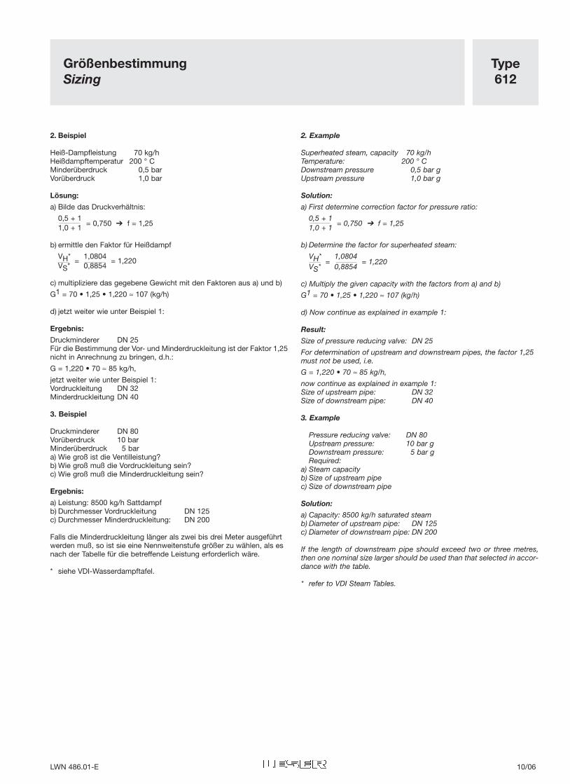
2. Beispiel
Heiß-Dampfleistung 70 kg/hHeißdampftemperatur 200 ° CMinderüberdruck 0,5 barVorüberdruck 1,0 bar
Lösung:
a) Bilde das Druckverhältnis:
0,5 + 11,0 + 1
= 0,750 ➔ f = 1,25
b) ermittle den Faktor für Heißdampf
VH* 1,0804VS*
=0,8854
= 1,220
c) multipliziere das gegebene Gewicht mit den Faktoren aus a) und b)
G1 = 70 • 1,25 • 1,220 ≈ 107 (kg/h)
d) jetzt weiter wie unter Beispiel 1:
Ergebnis:
Druckminderer DN 25Für die Bestimmung der Vor- und Minderdruckleitung ist der Faktor 1,25nicht in Anrechnung zu bringen, d.h.:
G = 1,220 • 70 ≈ 85 kg/h,
jetzt weiter wie unter Beispiel 1:Vordruckleitung DN 32Minderdruckleitung DN 40
3. Beispiel
Druckminderer DN 80Vorüberdruck 10 barMinderüberdruck 5 bar a) Wie groß ist die Ventilleistung?b) Wie groß muß die Vordruckleitung sein?c) Wie groß muß die Minderdruckleitung sein?
Ergebnis:
a) Leistung: 8500 kg/h Sattdampfb) Durchmesser Vordruckleitung DN 125c) Durchmesser Minderdruckleitung: DN 200
Falls die Minderdruckleitung länger als zwei bis drei Meter ausgeführtwerden muß, so ist sie eine Nennweitenstufe größer zu wählen, als esnach der Tabelle für die betreffende Leistung erforderlich wäre.
* siehe VDI-Wasserdampftafel.
2. Example
Superheated steam, capacity 70 kg/hTemperature: 200 ° CDownstream pressure 0,5 bar gUpstream pressure 1,0 bar g
Solution:
a) First determine correction factor for pressure ratio:
0,5 + 11,0 + 1
= 0,750 ➔ f = 1,25
b) Determine the factor for superheated steam:
VH* 1,0804VS*
=0,8854
= 1,220
c) Multiply the given capacity with the factors from a) and b)
G1 = 70 • 1,25 • 1,220 ≈ 107 (kg/h)
d) Now continue as explained in example 1:
Result:
Size of pressure reducing valve: DN 25
For determination of upstream and downstream pipes, the factor 1,25must not be used, i.e.
G = 1,220 • 70 ≈ 85 kg/h,
now continue as explained in example 1:Size of upstream pipe: DN 32Size of downstream pipe: DN 40
3. Example
Pressure reducing valve: DN 80Upstream pressure: 10 bar gDownstream pressure: 5 bar gRequired:
a) Steam capacityb) Size of upstream pipec) Size of downstream pipe
Solution:
a) Capacity: 8500 kg/h saturated steamb) Diameter of upstream pipe: DN 125c) Diameter of downstream pipe: DN 200
If the length of downstream pipe should exceed two or three metres,then one nominal size larger should be used than that selected in accor-dance with the table.
* refer to VDI Steam Tables.
LWN 486.01-E 10/06
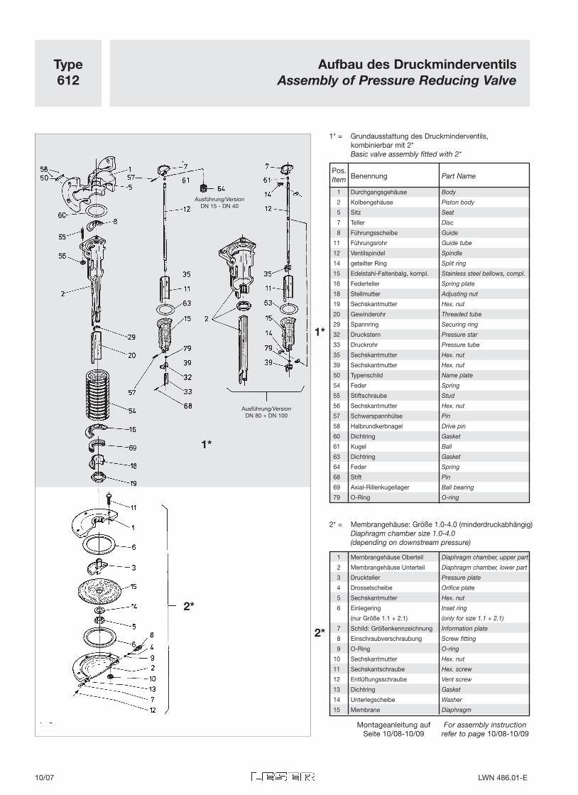
Type612
Aufbau des DruckminderventilsAssembly of Pressure Reducing Valve
Ausführung/VersionDN 15 - DN 40
Ausführung/VersionDN 80 + DN 100
Montageanleitung aufSeite 10/08-10/09
For assembly instructionrefer to page 10/08-10/09
2*
1*
2*
1*
1* = Grundausstattung des Druckminderventils,kombinierbar mit 2*Basic valve assembly fitted with 2*
Pos.Benennung Part NameItem
1 Durchgangsgehäuse Body
2 Kolbengehäuse Piston body
5 Sitz Seat
7 Teller Disc
8 Führungsscheibe Guide
11 Führungsrohr Guide tube
12 Ventilspindel Spindle
14 geteilter Ring Split ring
15 Edelstahl-Faltenbalg, kompl. Stainless steel bellows, compl.
16 Federteller Spring plate
18 Stellmutter Adjusting nut
19 Sechskantmutter Hex. nut
20 Gewinderohr Threaded tube
29 Spannring Securing ring
32 Druckstern Pressure star
33 Druckrohr Pressure tube
35 Sechskantmutter Hex. nut
39 Sechskantmutter Hex. nut
50 Typenschild Name plate
54 Feder Spring
55 Stiftschraube Stud
56 Sechskantmutter Hex. nut
57 Schwerspannhülse Pin
58 Halbrundkerbnagel Drive pin
60 Dichtring Gasket
61 Kugel Ball
63 Dichtring Gasket
64 Feder Spring
68 Stift Pin
69 Axial-Rillenkugellager Ball bearing
79 O-Ring O-ring
2* = Membrangehäuse: Größe 1.0-4.0 (minderdruckabhängig)Diaphragm chamber size 1.0-4.0(depending on downstream pressure)
1 Membrangehäuse Oberteil Diaphragm chamber, upper part
2 Membrangehäuse Unterteil Diaphragm chamber, lower part
3 Druckteller Pressure plate
4 Drosselscheibe Orifice plate
5 Sechskantmutter Hex. nut
6 Einlegering Inset ring
(nur Größe 1.1 + 2.1) (only for size 1.1 + 2.1)
7 Schild: Größenkennzeichnung Information plate
8 Einschraubverschraubung Screw fitting
9 O-Ring O-ring
10 Sechskantmutter Hex. nut
11 Sechskantschraube Hex. screw
12 Entlüftungsschraube Vent screw
13 Dichtring Gasket
14 Unterlegscheibe Washer
15 Membrane Diaphragm
10/07 LWN 486.01-E
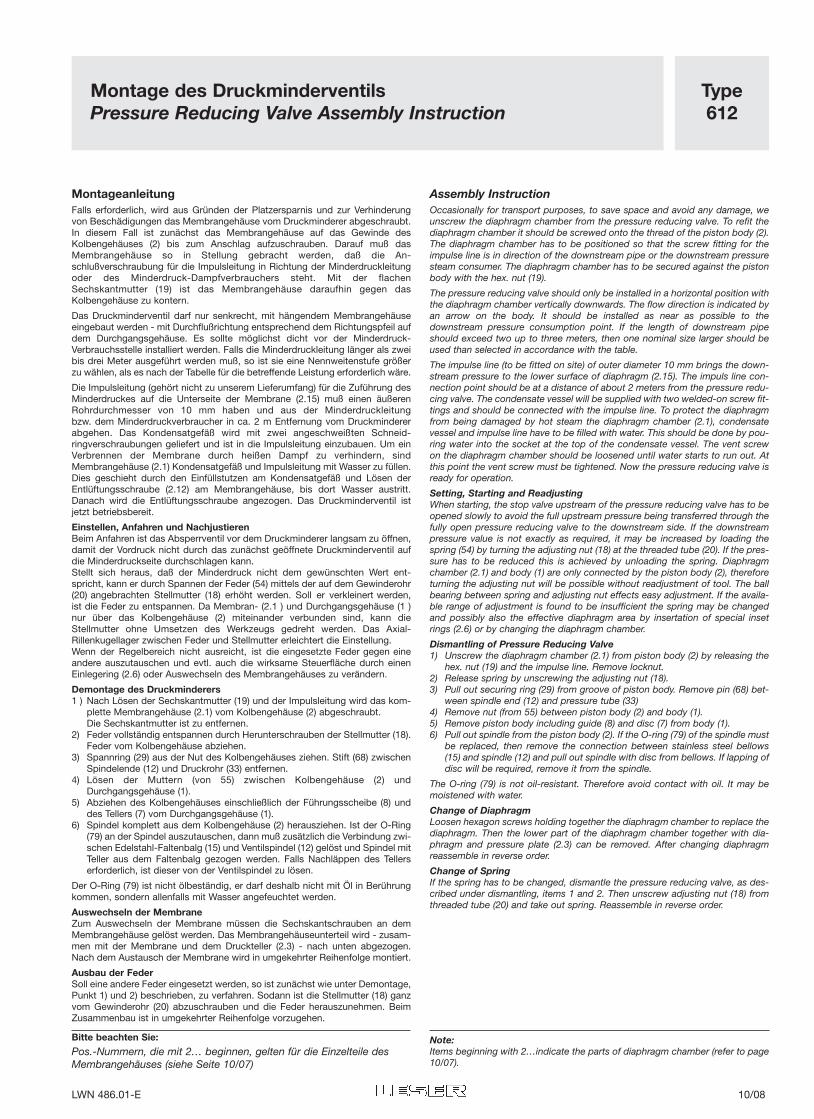
Type612
Montage des Druckminderventils Pressure Reducing Valve Assembly Instruction
MontageanleitungFalls erforderlich, wird aus Gründen der Platzersparnis und zur Verhinderungvon Beschädigungen das Membrangehäuse vom Druckminderer abgeschraubt.In diesem Fall ist zunächst das Membrangehäuse auf das Gewinde desKolbengehäuses (2) bis zum Anschlag aufzuschrauben. Darauf muß dasMembrangehäuse so in Stellung gebracht werden, daß die An-schlußverschraubung für die Impulsleitung in Richtung der Minderdruckleitungoder des Minderdruck-Dampfverbrauchers steht. Mit der flachenSechskantmutter (19) ist das Membrangehäuse daraufhin gegen dasKolbengehäuse zu kontern.
Das Druckminderventil darf nur senkrecht, mit hängendem Membrangehäuseeingebaut werden - mit Durchflußrichtung entsprechend dem Richtungspfeil aufdem Durchgangsgehäuse. Es sollte möglichst dicht vor der Minderdruck-Verbrauchsstelle installiert werden. Falls die Minderdruckleitung länger als zweibis drei Meter ausgeführt werden muß, so ist sie eine Nennweitenstufe größerzu wählen, als es nach der Tabelle für die betreffende Leistung erforderlich wäre.
Die Impulsleitung (gehört nicht zu unserem Lieferumfang) für die Zuführung desMinderdruckes auf die Unterseite der Membrane (2.15) muß einen äußerenRohrdurchmesser von 10 mm haben und aus der Minderdruckleitungbzw. dem Minderdruckverbraucher in ca. 2 m Entfernung vom Druckmindererabgehen. Das Kondensatgefäß wird mit zwei angeschweißten Schneid-ringverschraubungen geliefert und ist in die Impulsleitung einzubauen. Um einVerbrennen der Membrane durch heißen Dampf zu verhindern, sindMembrangehäuse (2.1) Kondensatgefäß und Impulsleitung mit Wasser zu füllen.Dies geschieht durch den Einfüllstutzen am Kondensatgefäß und Lösen derEntlüftungsschraube (2.12) am Membrangehäuse, bis dort Wasser austritt.Danach wird die Entlüftungsschraube angezogen. Das Druckminderventil istjetzt betriebsbereit.
Einstellen, Anfahren und NachjustierenBeim Anfahren ist das Absperrventil vor dem Druckminderer langsam zu öffnen,damit der Vordruck nicht durch das zunächst geöffnete Druckminderventil aufdie Minderdruckseite durchschlagen kann.Stellt sich heraus, daß der Minderdruck nicht dem gewünschten Wert ent-spricht, kann er durch Spannen der Feder (54) mittels der auf dem Gewinderohr(20) angebrachten Stellmutter (18) erhöht werden. Soll er verkleinert werden,ist die Feder zu entspannen. Da Membran- (2.1 ) und Durchgangsgehäuse (1 )nur über das Kolbengehäuse (2) miteinander verbunden sind, kann dieStellmutter ohne Umsetzen des Werkzeugs gedreht werden. Das Axial-Rillenkugellager zwischen Feder und Stellmutter erleichtert die Einstellung.Wenn der Regelbereich nicht ausreicht, ist die eingesetzte Feder gegen eineandere auszutauschen und evtl. auch die wirksame Steuerfläche durch einenEinlegering (2.6) oder Auswechseln des Membrangehäuses zu verändern.
Demontage des Druckminderers1 ) Nach Lösen der Sechskantmutter (19) und der Impulsleitung wird das kom-
plette Membrangehäuse (2.1) vom Kolbengehäuse (2) abgeschraubt.Die Sechskantmutter ist zu entfernen.
2) Feder vollständig entspannen durch Herunterschrauben der Stellmutter (18).Feder vom Kolbengehäuse abziehen.
3) Spannring (29) aus der Nut des Kolbengehäuses ziehen. Stift (68) zwischenSpindelende (12) und Druckrohr (33) entfernen.
4) Lösen der Muttern (von 55) zwischen Kolbengehäuse (2) undDurchgangsgehäuse (1).
5) Abziehen des Kolbengehäuses einschließlich der Führungsscheibe (8) unddes Tellers (7) vom Durchgangsgehäuse (1).
6) Spindel komplett aus dem Kolbengehäuse (2) herausziehen. Ist der O-Ring(79) an der Spindel auszutauschen, dann muß zusätzlich die Verbindung zwi-schen Edelstahl-Faltenbalg (15) und Ventilspindel (12) gelöst und Spindel mitTeller aus dem Faltenbalg gezogen werden. Falls Nachläppen des Tellerserforderlich, ist dieser von der Ventilspindel zu lösen.
Der O-Ring (79) ist nicht ölbeständig, er darf deshalb nicht mit Öl in Berührungkommen, sondern allenfalls mit Wasser angefeuchtet werden.
Auswechseln der MembraneZum Auswechseln der Membrane müssen die Sechskantschrauben an demMembrangehäuse gelöst werden. Das Membrangehäuseunterteil wird - zusam-men mit der Membrane und dem Druckteller (2.3) - nach unten abgezogen.Nach dem Austausch der Membrane wird in umgekehrter Reihenfolge montiert.
Ausbau der FederSoll eine andere Feder eingesetzt werden, so ist zunächst wie unter Demontage,Punkt 1) und 2) beschrieben, zu verfahren. Sodann ist die Stellmutter (18) ganzvom Gewinderohr (20) abzuschrauben und die Feder herauszunehmen. BeimZusammenbau ist in umgekehrter Reihenfolge vorzugehen.
Bitte beachten Sie:
Pos.-Nummern, die mit 2… beginnen, gelten für die Einzelteile desMembrangehäuses (siehe Seite 10/07)
Assembly InstructionOccasionally for transport purposes, to save space and avoid any damage, weunscrew the diaphragm chamber from the pressure reducing valve. To refit thediaphragm chamber it should be screwed onto the thread of the piston body (2).The diaphragm chamber has to be positioned so that the screw fitting for theimpulse line is in direction of the downstream pipe or the downstream pressuresteam consumer. The diaphragm chamber has to be secured against the pistonbody with the hex. nut (19).
The pressure reducing valve should only be installed in a horizontal position withthe diaphragm chamber vertically downwards. The flow direction is indicated byan arrow on the body. It should be installed as near as possible to thedownstream pressure consumption point. If the length of downstream pipeshould exceed two up to three meters, then one nominal size larger should beused than selected in accordance with the table.
The impulse line (to be fitted on site) of outer diameter 10 mm brings the down-stream pressure to the lower surface of diaphragm (2.15). The impuls line con-nection point should be at a distance of about 2 meters from the pressure redu-cing valve. The condensate vessel will be supplied with two welded-on screw fit-tings and should be connected with the impulse line. To protect the diaphragmfrom being damaged by hot steam the diaphragm chamber (2.1), condensatevessel and impulse line have to be filled with water. This should be done by pou-ring water into the socket at the top of the condensate vessel. The vent screwon the diaphragm chamber should be loosened until water starts to run out. Atthis point the vent screw must be tightened. Now the pressure reducing valve isready for operation.
Setting, Starting and ReadjustingWhen starting, the stop valve upstream of the pressure reducing valve has to beopened slowly to avoid the full upstream pressure being transferred through thefully open pressure reducing valve to the downstream side. If the downstreampressure value is not exactly as required, it may be increased by loading thespring (54) by turning the adjusting nut (18) at the threaded tube (20). If the pres-sure has to be reduced this is achieved by unloading the spring. Diaphragmchamber (2.1) and body (1) are only connected by the piston body (2), thereforeturning the adjusting nut will be possible without readjustment of tool. The ballbearing between spring and adjusting nut effects easy adjustment. If the availa-ble range of adjustment is found to be insufficient the spring may be changedand possibly also the effective diaphragm area by insertation of special insetrings (2.6) or by changing the diaphragm chamber.
Dismantling of Pressure Reducing Valve1) Unscrew the diaphragm chamber (2.1) from piston body (2) by releasing the
hex. nut (19) and the impulse line. Remove locknut.2) Release spring by unscrewing the adjusting nut (18).3) Pull out securing ring (29) from groove of piston body. Remove pin (68) bet-
ween spindle end (12) and pressure tube (33)4) Remove nut (from 55) between piston body (2) and body (1).5) Remove piston body including guide (8) and disc (7) from body (1).6) Pull out spindle from the piston body (2). If the O-ring (79) of the spindle must
be replaced, then remove the connection between stainless steel bellows(15) and spindle (12) and pull out spindle with disc from bellows. If lapping ofdisc will be required, remove it from the spindle.
The O-ring (79) is not oil-resistant. Therefore avoid contact with oil. It may bemoistened with water.
Change of DiaphragmLoosen hexagon screws holding together the diaphragm chamber to replace thediaphragm. Then the lower part of the diaphragm chamber together with dia-phragm and pressure plate (2.3) can be removed. After changing diaphragmreassemble in reverse order.
Change of SpringIf the spring has to be changed, dismantle the pressure reducing valve, as des-cribed under dismantling, items 1 and 2. Then unscrew adjusting nut (18) fromthreaded tube (20) and take out spring. Reassemble in reverse order.
Note:Items beginning with 2…indicate the parts of diaphragm chamber (refer to page10/07).
LWN 486.01-E 10/08
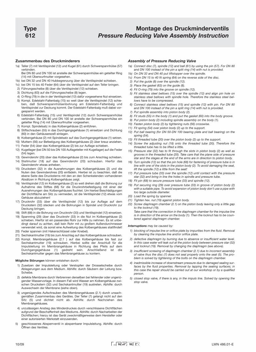
Type612
Montage des DruckminderventilsPressure Reducing Valve Assembly Instruction
Zusammenbau des Druckminderers1a) Teller (7) mit Ventilspindel (12) und Kugel (61) durch Schwerspannhülse (57)
verbinden.Bei DN 80 und DN 100 ist anstelle der Schwerspannhülse ein geteilter Ring(14) mit Überwurfmutter vorgesehen.
1b) bei DN 32 und DN 40 Hubbegrenzung über die Ventilspindel schieben.1c) bei DN 15 bis 40 Feder (64) über die Ventilspindel auf den Teller bringen.
2) Führungsscheibe (8) über die Ventilspindel (12) schieben.3) Dichtung (63) auf die Führungsscheibe (8) legen.4) O-Ring (79) in die in der Ventilspindel (12) dafür vorgesehene Nut einsetzen.5) Kompl. Edelstahl-Faltenbalg (15) so weit über die Ventilspindel (12) schie-
ben, daß Schwerspannhülsenbohrung am Edelstahl-Faltenbalg undVentilspindel zur Deckung kommt. Der Edelstahl-Faltenbalg muß dabei vor-gespannt werden.
6) Edelstahl-Faltenbalg (15) und Ventilspindel (12) durch Schwerspannhülseverbinden. Bei DN 80 und DN 100 ist anstelle der Schwerspannhülse eingeteilter Ring (14) mit Überwurfmutter vorgesehen.
7) Kompl. Spindelsatz in das Kolbengehäuse (2) einführen.8) Stiftschrauben (55) in das Durchgangsgehäuse (1) einsetzen und Dichtung
(60) in den Gehäuserezeß einlegen.9) Kolbengehäuse (2) mit Spindelsatz auf das Durchgangsgehäuse (1) setzen.
10) Muttern (56) zur Befestigung des Kolbengehäuses (2) über kreuz anziehen.11) Feder (54) über das Kolbengehäuse (2) bis zur Auflage schieben.12) Kugellager (bei DN 50 bis DN 100 Auflageteller mit Kugellager) auf die Feder
(54) legen.13) Gewinderohr (20) über das Kolbengehäuse (2) bis zum Anschlag schieben.14) Stellmutter (18) auf das Gewinderohr (20) schrauben. Hierfür das
Gewinderohr etwas anheben.15) Druckstern (32) in die Ausnehmungen des Kolbengehäuses (2) und die
Nuten des Gewinderohres (20) einfädeln. Hierbei ist zu beachten, daß dieebene Seite des Drucksterns mit den an den Schenkelenden vorhandenenAbsätzen in Richtung Kolbengehäuse zeigt.
16) Ventilspindel (12) im Kolbengehäuse (2) so weit drehen daß die Bohrung zurAufnahme des Stiftes (68) für die Druckrohrbefestigung mit einer derAusnehmungen des Kolbengehäuses fluchtet. Um hierbei Beschädigungender Dichtfläche am Sitz zu vermeiden, ist die Ventilspindel (12) etwas vomGehäuse abzuziehen!
17) Druckrohr (33) über die Ventilspindel (12) bis zur Auflage auf demDruckstern (32) stecken und die Bohrungen in Spindel und Druckrohr zurDeckung bringen.
18) Stift (68) in die Bohrung von Druckrohr (33) und Ventilspindel (12) einsetzen.19) Spannring (29) über das Druckrohr (33) in die Nut im Kolbengehäuse (2)
schieben. Hierfür ist ein passendes Rohr zur Hilfe zu nehmen. Es ist unbe-dingt darauf zu achten, daß kein Rohr mit zu großem Außendurchmesserverwendet wird, da sonst eine Aufweitung des Kolbengehäuses stattfindet!
20) Feder spannen (mit Hakenschlüssel oder Knebel).21) Sechskantmutter (19) bis zum Anschlag auf das Kolbengehäuse schrauben.22) Kompl. Membrangehäuse (2.1 ) auf das Kolbengehäuse bis fast zur
Sechskantmutter (19) schrauben. Hierbei sollte der Anschluß für dieImpulsleitung im Membrangehäuse in Richtung des Pfeils auf demDurchgangsgehäuse (1) gedreht sein. Anschließend ist dieSechskantmutter gegen das Membrangehäuse zu kontern.
Mögliche Störungen können entstehen durch:
1) Zusetzen der Impulsleitung oder Verstopfen der Drosselscheibe durchAblagerungen aus dem Medium. Abhilfe: durch Säubern der Leitung bzw.Scheibe.
2) defekte Membrane durch Verbrennen derselben bei fehlender oder ungenü-gender Wasservorlage. In diesem Fall wird Wasser am Kolbengehäuse zwi-schen Druckstern (32) und Sechskantmutter (19) austreten. Abhilfe: durchAuswechseln der Membrane (siehe oben).
3) ungenügendes Aufschrauben des Membrangehäuses (2.1) durch unsach-gemäßen Zusammenbau des Gerätes. Der Teller (7) gelangt nicht auf denSitz (5) und dichtet nicht ab. Abhilfe: durch Nachziehen desMembrangehäuses.
4) unzulässigen Anstieg des Minderdruckes durch verschlissene Dichtflächenaufgrund der Beschaffenheit des Mediums. Abhilfe: durch Nacharbeiten derDichtflächen; hierzu ist das Gerät zweckmäßigerweise dem Hersteller odereiner autorisierten Werkstatt einzusenden.
5) geschlossenes Absperrventil in absperrbarer Impulsleitung. Abhilfe: durchÖffnen des Ventiles.
Assembly of Pressure Reducing Valve1a) Connect disc (7), spindle (12) and ball (61) by using the pin (57). For DN 80
and DN 100 instead of the pin a split ring (14) with nut is provided.1b) On DN 32 and DN 40 put liftstopper over the spindle.1c) From DN 15 to 40 fit spring (64) on the reverse side of the disc.
2) Put the guide (8) over the spindle (12).3) Place the gasket (63) on the guide (8).4) Fit O-ring (79) into the groove on spindle (12).5) Fit stainless steel bellows (15) over the spindle (12) and align pin hole on
stainless steel bellows with spindle hole. Therefore the stainless steel bel-lows have to be compressed.
6) Connect stainless steel bellows (15) and spindle (12) with pin. For DN 80and DN 100 instead of the pin a split ring (14) with nut is provided.
7) Put spindle assembly into piston body (2).8) Fit studs (55) in the body (1) and put the gasket (60) into the body groove.9) Put piston body (2) including spindle assembly on the body (1).
10) Fasten piston body (2) by tightening nuts (56) crosswise.11) Fit spring (54) over piston body (2) up to the support.12) Put ball bearing (for DN 50-DN 100 bearing plate and ball bearing) on the
spring (54).13) Fit threaded tube (20) over the piston body (2) up to the support.14) Screw the adjusting nut (18) onto the threaded tube (20). Therefore the
threaded tube has to be lifted a little.15) Pressure star (32) has to fit through the slots in piston body (2) as well as
grooves in the threaded tube (20). Take care that the plane side of pressurestar and the stages at the end of the arms are in direction to piston body.
16) Turn spindle (12) so that the pin hole (68) for fastening of pressure tube is inline with one of the slots in the piston body (2). To avoid damaging the seat,lift the spindle (12) a little from the seat!
17) Put pressure tube (33) over the spindle (12) until contact with the pressurestar (32) and bring in line the holes in spindle and pressure tube.
18) Fit pin (68) to secure pressure tube (33) and spindle (12).19) Put securing ring (29) over pressure tube (33) in groove of piston body (2)
with a suitable pipe. To avoid expansion of piston body don’t use a pipe withtoo large outside diameter.
20) Load the spring by spanner.21) Tighten hex. nut (19) against piston body.22) Screw diaphragm chamber (2.1) on the piston body leaving only a little gap
to the locknut (19).Take care that the connection in the diaphragm chamber for the impulse lineis in direction of the arrow on the body (1). Then the locknut has to be coun-tered against diaphragm chamber.
Interruptions may be caused by:
1) blocking of impulse line or orifice plate by impurities from the fluid. Removalby cleaning the impulse line and/or orifice plate.
2) defective diaphragm by burning due to absence or insufficient water level.In this case water will leak out at the piston body between pressure star (32)and locknut (19). Removal by changing the diaphragm (see above).
3) insufficient screwing of diaphragm chamber (2.1) due to incorrect assemblyof valve thus the disc (7) does not seal properly onto the seat (5). The pro-blem is solved by tightening of the bolts on the diaphragm chamber.
4) inadmissible increase of downstream pressure due to damaged sealing sur-faces by the fluid properties. Removal by lapping the sealing surfaces; inthis case the repair should be carried out at our workshop or by a qualifiedperson.
5) closed stop valve, if there is any, in the impuls line. Solved by opening thestop valve.
10/09 LWN 486.01-E
AddresseePlease send the requested copies to:
Name:
Company:
Address:
E-Mail:
Please send your request to our Sales Center
To: LESER GmbH & Co. KG Fax: +49 (40) 251 65-500
Date: From:
Catalog order:
HighPerformance Catalog 1
Flanged Safety Relief Valves
Series 441Series XXLSeries 444
HighPerformance Catalog 2
Flanged Safety Relief Valves
Series 441 Full nozzleSeries 458
CompactPerformance
Threaded Safety Relief Valves
Series 437Series 459
API
Flanged Safety Relief Valves
Series 526
Printed version
No. of copies:
Printed version
No. of copies:
Printed version
No. of copies:
Printed version
No. of copies:
Clean Service Safety Relief Valves
Series 48X
Critical Service
Safety Relief Valves
Series 447Series 546
Modulate Action
Flanged Safety Relief Valves
Series 429Series 433
S & R
Safety Relief Valves for special or regional applications
Series L & WSeries TRDFSeries TRDG Series SBD Type 612
Printed version
No. of copies:
Printed version
No. of copies:
Printed version
No. of copies:
Printed version
No. of copies:
CD order:
VALVESTAR®
– Ultimate sizing program – Consideration of all relevant codes and standards – Comprehensive documentation (sectional drawings, parts lists) – Different language versions– Help function No. of copies:
Fax OrderFax Order

S&R CatalogEdition April 2006
LWN 486.01-E / 04.2006 / 1500
The-Safety-Valve.com
LESER GmbH & Co. KG 20537 Hamburg, Wendenstr. 133-135 Fon +49 (40) 251 65-100 E-Mail: [email protected] Hamburg, P.O.Box 26 16 51 Fax +49 (40) 251 65-500 www.leser.com