Embed Size (px)
Citation preview
1
Flags at IV3PRK: from West Coast to Florida models
Upgrading from the rotatable Flag by W7IUV, and the original K6SE design, to the “Waller Flag”, an end-fire rotatable two loops array by NX4D and N4IS.
Part 1 - Modeling with EZNEC
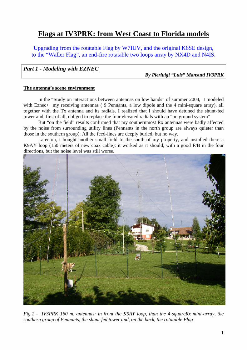
By Pierluigi “Luis” Mansutti IV3PRK The antenna’s scene environment In the “Study on interactions between antennas on low bands” of summer 2004, I modeled with Eznec+ my receiving antennas ( 9 Pennants, a low dipole and the 4 mini-square array), all together with the Tx antenna and its radials. I realized that I should have detuned the shunt-fed tower and, first of all, obliged to replace the four elevated radials with an “on ground system” . But “on the field” results confirmed that my southernmost Rx antennas were badly affected by the noise from surrounding utility lines (Pennants in the north group are always quieter than those in the southern group). All the feed-lines are deeply buried, but no way.
Later on, I bought another small field to the south of my property, and installed there a K9AY loop (150 meters of new coax cable): it worked as it should, with a good F/B in the four directions, but the noise level was still worse.
Fig.1 - IV3PRK 160 m. antennas: in front the K9AY loop, than the 4-squareRx mini-array, the southern group of Pennants, the shunt-fed tower and, on the back, the rotatable Flag
2
The W7IUV rotatable Flag
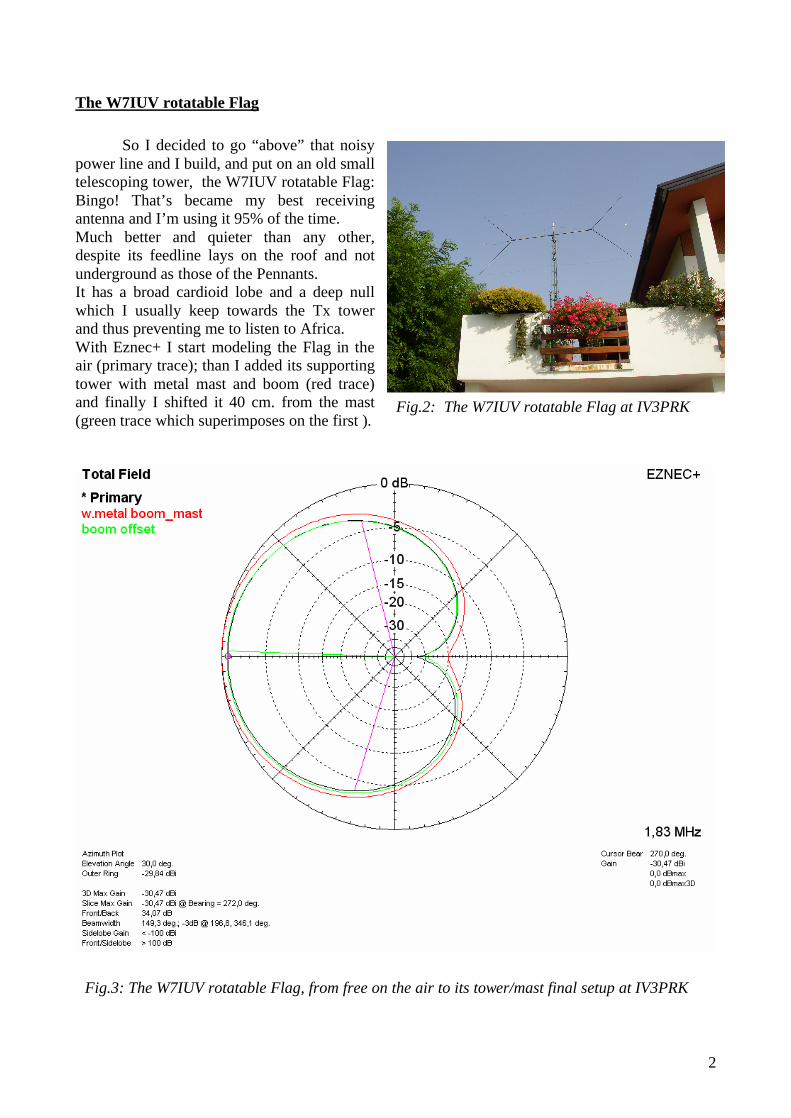
So I decided to go “above” that noisy power line and I build, and put on an old small telescoping tower, the W7IUV rotatable Flag: Bingo! That’s became my best receiving antenna and I’m using it 95% of the time. Much better and quieter than any other, despite its feedline lays on the roof and not underground as those of the Pennants. It has a broad cardioid lobe and a deep null which I usually keep towards the Tx tower and thus preventing me to listen to Africa. With Eznec+ I start modeling the Flag in the air (primary trace); than I added its supporting tower with metal mast and boom (red trace) and finally I shifted it 40 cm. from the mast (green trace which superimposes on the first ).
Fig.2: The W7IUV rotatable Flag at IV3PRK
Fig.3: The W7IUV rotatable Flag, from free on the air to its tower/mast final setup at IV3PRK
3
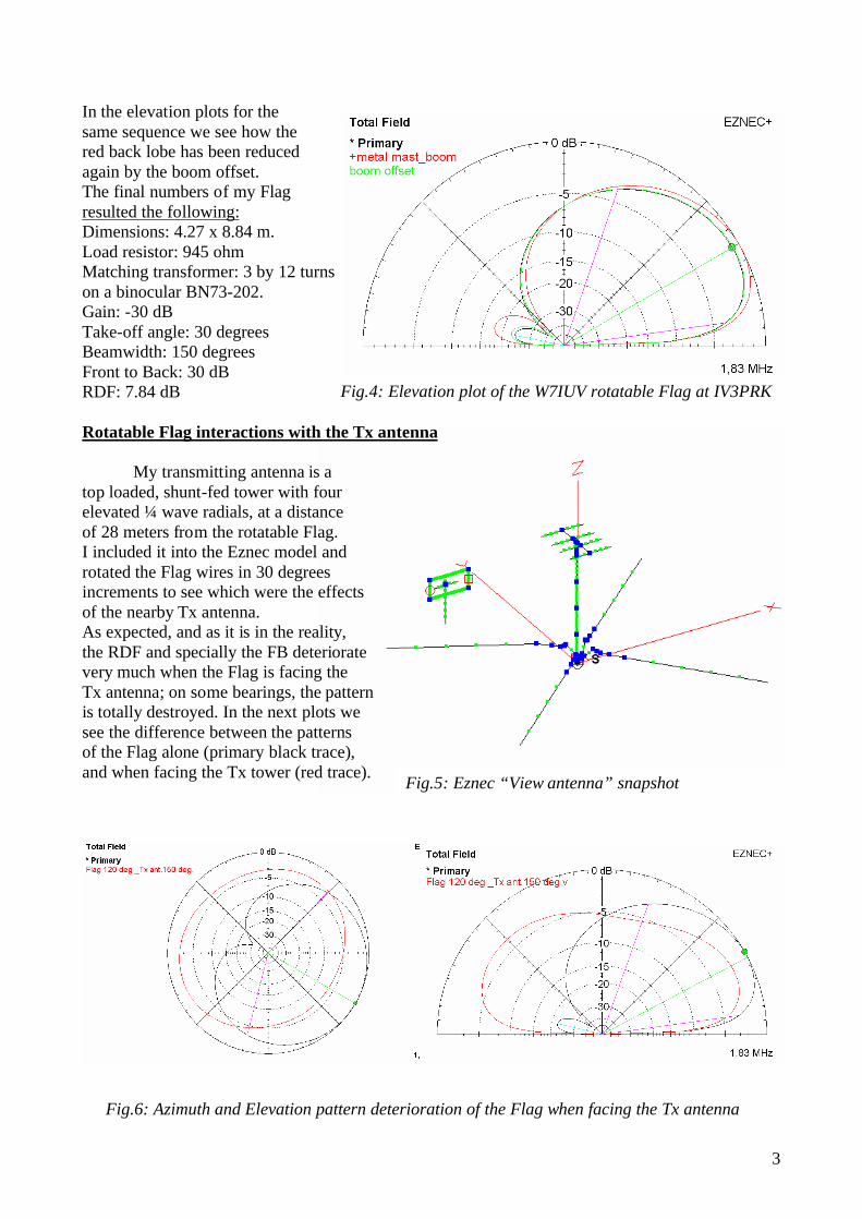
In the elevation plots for the same sequence we see how the red back lobe has been reduced again by the boom offset. The final numbers of my Flag resulted the following: Dimensions: 4.27 x 8.84 m. Load resistor: 945 ohm Matching transformer: 3 by 12 turns on a binocular BN73-202. Gain: -30 dB Take-off angle: 30 degrees Beamwidth: 150 degrees Front to Back: 30 dB RDF: 7.84 dB Rotatable Flag interactions with the Tx antenna My transmitting antenna is a top loaded, shunt-fed tower with four elevated ¼ wave radials, at a distance of 28 meters from the rotatable Flag. I included it into the Eznec model and rotated the Flag wires in 30 degrees increments to see which were the effects of the nearby Tx antenna. As expected, and as it is in the reality, the RDF and specially the FB deteriorate very much when the Flag is facing the Tx antenna; on some bearings, the pattern is totally destroyed. In the next plots we see the difference between the patterns of the Flag alone (primary black trace), and when facing the Tx tower (red trace).
Fig.4: Elevation plot of the W7IUV rotatable Flag at IV3PRK
Fig.5: Eznec “View antenna” snapshot
Fig.6: Azimuth and Elevation pattern deterioration of the Flag when facing the Tx antenna
4
Rotatable 160 m. Flag in the IV3PRK environmentRDF in dB vs. Flag bearing degrees
6789
101112
270
300
330
360 30 60 90 12
015
018
021
024
027
0
Tx ant. - 4 elev.rad.Tower detuned
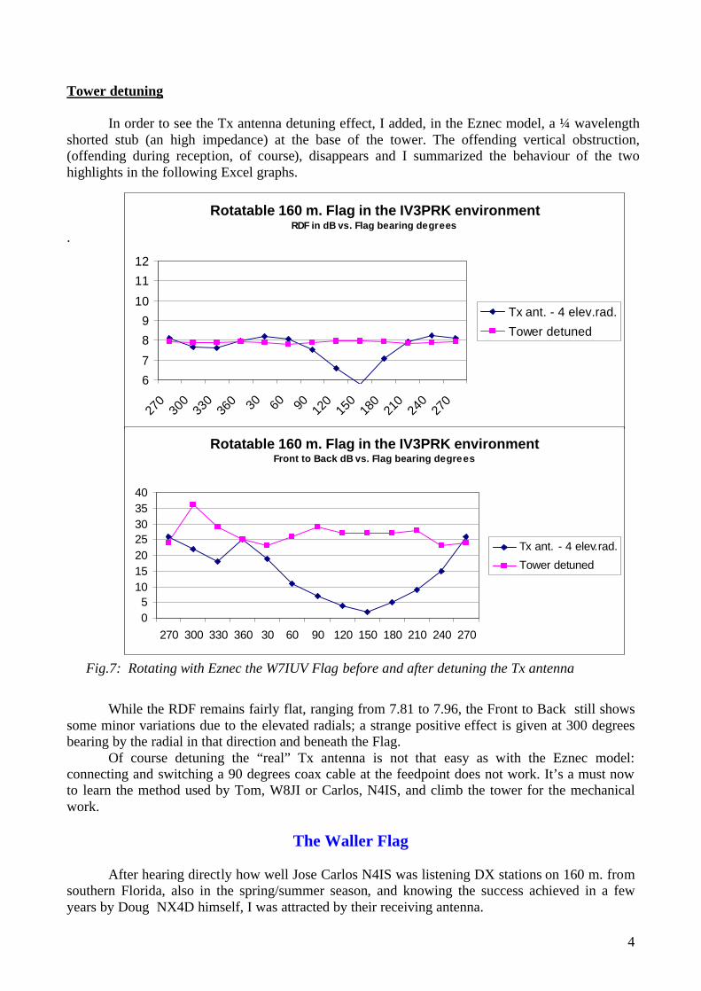
Tower detuning In order to see the Tx antenna detuning effect, I added, in the Eznec model, a ¼ wavelength shorted stub (an high impedance) at the base of the tower. The offending vertical obstruction, (offending during reception, of course), disappears and I summarized the behaviour of the two highlights in the following Excel graphs. . While the RDF remains fairly flat, ranging from 7.81 to 7.96, the Front to Back still shows some minor variations due to the elevated radials; a strange positive effect is given at 300 degrees bearing by the radial in that direction and beneath the Flag. Of course detuning the “real” Tx antenna is not that easy as with the Eznec model: connecting and switching a 90 degrees coax cable at the feedpoint does not work. It’s a must now to learn the method used by Tom, W8JI or Carlos, N4IS, and climb the tower for the mechanical work.
The Waller Flag After hearing directly how well Jose Carlos N4IS was listening DX stations on 160 m. from southern Florida, also in the spring/summer season, and knowing the success achieved in a few years by Doug NX4D himself, I was attracted by their receiving antenna.
Rotatable 160 m. Flag in the IV3PRK environmentFront to Back dB vs. Flag bearing degrees
05
10152025303540
270 300 330 360 30 60 90 120 150 180 210 240 270
Tx ant. - 4 elev.rad.Tower detuned
Fig.7: Rotating with Eznec the W7IUV Flag before and after detuning the Tx antenna
5
It is a rotatable end-fire close array of two Flags, originated by Doug Waller NX4D and thus named “The Waller Flag” by Jose Carlos N4IS, who built a couple of them with improvements.
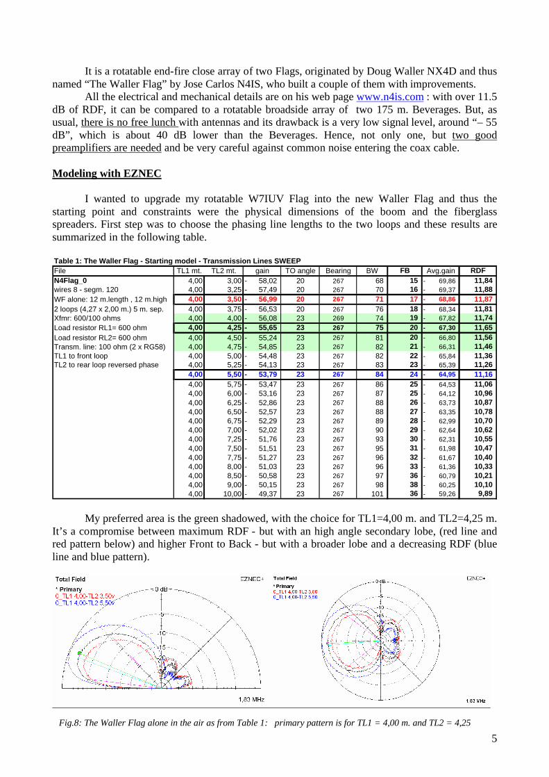
All the electrical and mechanical details are on his web page www.n4is.com : with over 11.5 dB of RDF, it can be compared to a rotatable broadside array of two 175 m. Beverages. But, as usual, there is no free lunch with antennas and its drawback is a very low signal level, around “– 55 dB”, which is about 40 dB lower than the Beverages. Hence, not only one, but two good preamplifiers are needed and be very careful against common noise entering the coax cable. Modeling with EZNEC I wanted to upgrade my rotatable W7IUV Flag into the new Waller Flag and thus the starting point and constraints were the physical dimensions of the boom and the fiberglass spreaders. First step was to choose the phasing line lengths to the two loops and these results are summarized in the following table. Table 1: The Waller Flag - Starting model - Transmission Lines SWEEPFile TL1 mt. TL2 mt. gain TO angle Bearing BW FB Avg.gain RDFN4Flag_0 4,00 3,00 58,02- 20 267 68 15 69,86- 11,84 wires 8 - segm. 120 4,00 3,25 57,49- 20 267 70 16 69,37- 11,88 WF alone: 12 m.length , 12 m.high 4,00 3,50 56,99- 20 267 71 17 68,86- 11,87 2 loops (4,27 x 2,00 m.) 5 m. sep. 4,00 3,75 56,53- 20 267 76 18 68,34- 11,81 Xfmr: 600/100 ohms 4,00 4,00 56,08- 23 269 74 19 67,82- 11,74 Load resistor RL1= 600 ohm 4,00 4,25 55,65- 23 267 75 20 67,30- 11,65 Load resistor RL2= 600 ohm 4,00 4,50 55,24- 23 267 81 20 66,80- 11,56 Transm. line: 100 ohm (2 x RG58) 4,00 4,75 54,85- 23 267 82 21 66,31- 11,46 TL1 to front loop 4,00 5,00 54,48- 23 267 82 22 65,84- 11,36 TL2 to rear loop reversed phase 4,00 5,25 54,13- 23 267 83 23 65,39- 11,26
4,00 5,50 53,79- 23 267 84 24 64,95- 11,16 4,00 5,75 53,47- 23 267 86 25 64,53- 11,06 4,00 6,00 53,16- 23 267 87 25 64,12- 10,96 4,00 6,25 52,86- 23 267 88 26 63,73- 10,87 4,00 6,50 52,57- 23 267 88 27 63,35- 10,78 4,00 6,75 52,29- 23 267 89 28 62,99- 10,70 4,00 7,00 52,02- 23 267 90 29 62,64- 10,62 4,00 7,25 51,76- 23 267 93 30 62,31- 10,55 4,00 7,50 51,51- 23 267 95 31 61,98- 10,47 4,00 7,75 51,27- 23 267 96 32 61,67- 10,40 4,00 8,00 51,03- 23 267 96 33 61,36- 10,33 4,00 8,50 50,58- 23 267 97 36 60,79- 10,21 4,00 9,00 50,15- 23 267 98 38 60,25- 10,10 4,00 10,00 49,37- 23 267 101 36 59,26- 9,89
My preferred area is the green shadowed, with the choice for TL1=4,00 m. and TL2=4,25 m. It’s a compromise between maximum RDF - but with an high angle secondary lobe, (red line and red pattern below) and higher Front to Back - but with a broader lobe and a decreasing RDF (blue line and blue pattern).
Fig.8: The Waller Flag alone in the air as from Table 1: primary pattern is for TL1 = 4,00 m. and TL2 = 4,25
6
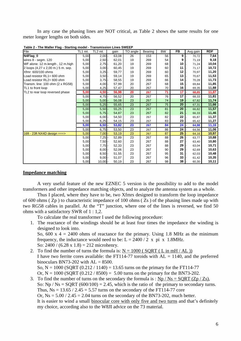
In any case the phasing lines are NOT critical, as Table 2 shows the same results for one meter longer lengths on both sides. Table 2 - The Waller Flag - Starting model - Transmission Lines SWEEPFile TL1 mt. TL2 mt. gain TO angle Bearing BW FB Avg.gain RDFN4Flag_0 5,00 2,00 63,08- 26 153 56 9 70,72- 7,64 wires 8 - segm. 120 5,00 2,50 62,01- 19 269 54 9 71,19- 9,18 WF alone: 12 m.length , 12 m.high 5,00 2,75 61,20- 19 269 68 10 71,24- 10,04 2 loops (4,27 x 2,00 m.) 5 m. sep. 5,00 3,00 60,45- 19 269 60 11 71,17- 10,72 Xfmr: 600/100 ohms 5,00 3,25 59,77- 19 269 60 12 70,97- 11,20 Load resistor RL1= 600 ohm 5,00 3,50 59,14- 19 269 65 13 70,67- 11,53 Load resistor RL2= 600 ohm 5,00 3,75 58,55- 19 269 66 14 70,28- 11,73 Transm. line: 100 ohm (2 x RG58) 5,00 4,00 57,99- 20 267 68 15 69,84- 11,85 TL1 to front loop 5,00 4,25 57,47- 20 267 70 16 69,35- 11,88 TL2 to rear loop reversed phase 5,00 4,50 56,98- 20 267 71 17 68,85- 11,87
5,00 4,75 56,52- 20 267 76 17 68,33- 11,81 5,00 5,00 56,08- 23 267 74 19 67,82- 11,74 5,00 5,25 55,65- 23 267 75 20 67,31- 11,66 5,00 5,50 55,25- 23 267 81 20 66,82- 11,57 5,00 5,75 54,87- 23 267 82 21 66,33- 11,46 5,00 6,00 54,50- 23 267 82 22 65,87- 11,37 5,00 6,25 54,15- 23 267 83 23 65,42- 11,27 5,00 6,50 53,82- 23 267 84 24 64,98- 11,16 5,00 6,75 53,50- 23 267 86 24 64,56- 11,06
16ft - 23ft NX4D design ===> 5,00 7,00 53,19- 23 267 87 25 64,16- 10,97 5,00 7,25 52,89- 23 267 88 26 63,77- 10,88 5,00 7,50 52,60- 23 267 88 27 63,40- 10,80 5,00 7,75 52,33- 23 267 88 29 63,04- 10,71 5,00 8,00 52,06- 23 267 90 29 62,69- 10,63 5,00 8,50 51,55- 23 267 95 31 62,03- 10,48 5,00 9,00 51,07- 23 267 96 33 61,42- 10,35 5,00 10,00 50,19- 23 267 98 38 60,30- 10,11
Impedance matching A very useful feature of the new EZNEC 5 version is the possibility to add to the model transformers and other impedance matching objects, and to analyze the antenna system as a whole. Thus I placed, where they have to be, two Xfmrs designed to transform the loop impedance of 600 ohms ( Zp ) to characteristic impedance of 100 ohms ( Zs ) of the phasing lines made up with two RG58 cables in parallel. At the “T” junction, where one of the lines is reversed, we find 50 ohms with a satisfactory SWR of 1 : 1,2. To calculate the real transformer I used the following procedure:
1. The reactance of the windings should be at least four times the impedance the winding is designed to look into. So, 600 x 4 = 2400 ohms of reactance for the primary. Using 1.8 MHz as the minimum frequency, the inductance would need to be: L = 2400 / 2 x pi x 1.8MHz. So: 2400 / (6.28 x 1.8) = 212 microhenry.
2. To find the number of turns the formula is: N = 1000 ( SQRT ( L in mH / AL )) I have two ferrite cores available: the FT114-77 toroids with AL = 1140, and the preferred binoculars BN73-202 with AL = 8500. So, N = 1000 (SQRT (0.212 / 1140) = 13.65 turns on the primary for the FT114-77 Or, N = 1000 (SQRT (0.212 / 8500) = 5.00 turns on the primary for the BN73-202.
3. To find the number of turns on the secondary the formula is : Np / Ns = SQRT (Zp / Zs), So: Np / Ns = SQRT (600/100) = 2.45, which is the ratio of the primary to secondary turns. Thus, Ns = 13.65 / 2.45 = 5.57 turns on the secondary of the FT114-77 core Or, Ns = 5.00 / 2.45 = 2.04 turns on the secondary of the BN73-202, much better. It is easier to wind a small binocular core with only five and two turns and that’s definitely my choice, according also to the W8JI advice on the 73 material.
7
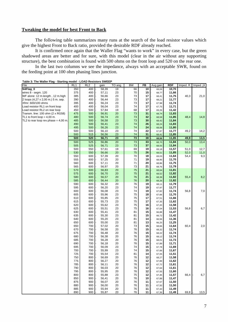
Tweaking the model for best Front to Back The following table summarizes many runs at the search of the load resistor values which
give the highest Front to Back ratio, provided the desirable RDF already reached. It is confirmed once again that the Waller Flag “wants to work” in every case, but the green
shadowed areas are better and for sure, with this model (clear in the air without any supporting structure), the best combination is found with 500 ohms on the front loop and 520 on the rear one.
In the last two columns we see the impedance, always with an acceptable SWR, found on the feeding point at 100 ohm phasing lines junction. Table 3: The Waller Flag - Starting model - LOAD Resistors SWEEPFile RL1 RL2 gain TO ang. BW FB Avg.gain RDF Imped. R. Imped. jXN4Flag_0 350 400 58,39- 19 66 10 69,09- 10,70 wires 8 - segm. 120 375 400 57,11- 23 70 15 68,77- 11,66 WF alone: 12 m.length , 12 m.high 385 400 56,66- 23 73 17 68,41- 11,75 40,3 21,0 2 loops (4,27 x 2,00 m.) 5 m. sep. 390 400 56,44- 23 73 17 68,21- 11,77 Xfmr: 600/100 ohms 395 400 56,24- 23 73 17 67,98- 11,74 Load resistor RL1 on front loop 400 400 56,04- 23 74 17 67,75- 11,71 Load resistor RL2 on rear loop 450 500 57,84- 19 68 17 69,26- 11,42 Transm. line: 100 ohm (2 x RG58) 475 500 56,91- 20 73 31 68,74- 11,83 TL1 to front loop = 4,00 m. 480 500 56,74- 23 73 32 68,59- 11,85 48,4 14,8 TL2 to rear loop rev.phase = 4,00 m. 485 500 56,58- 23 73 30 68,42- 11,84
490 500 56,41- 23 74 26 68,24- 11,83 495 500 56,26- 23 74 24 68,06- 11,80 500 500 56,10- 23 74 22 67,87- 11,77 49,2 14,2 500 515 56,56- 23 74 31 68,41- 11,85 500 520 56,71- 23 73 38 68,56- 11,85 49,9 13,5 500 525 56,86- 20 73 33 68,70- 11,84 50,0 13,4 505 525 56,71- 23 73 37 68,55- 11,84 500 550 57,61- 19 69 19 69,18- 11,57 51,0 12,7 530 550 56,66- 20 75 26 68,51- 11,85 52,0 11,0 550 600 57,39- 20 70 18 69,03- 11,64 54,4 9,3 555 600 57,25- 20 71 19 68,95- 11,70 560 600 57,11- 20 71 20 68,86- 11,75 565 600 56,97- 20 73 21 68,76- 11,79 570 600 56,83- 20 75 21 68,64- 11,81 575 600 56,70- 20 75 21 68,52- 11,82 580 600 56,57- 20 76 21 68,39- 11,82 55,4 8,2 585 600 56,44- 20 76 20 68,26- 11,82 590 600 56,32- 20 76 19 68,11- 11,79 595 600 56,20- 23 74 19 67,97- 11,77 600 600 56,08- 23 74 19 67,82- 11,74 56,8 7,0 605 600 55,96- 23 75 18 67,66- 11,70 610 600 55,85- 23 75 17 67,51- 11,66 615 600 55,73- 23 75 17 67,35- 11,62 620 600 55,62- 23 75 16 67,20- 11,58 625 600 55,51- 23 75 16 67,04- 11,53 56,8 6,7 630 600 55,41- 23 81 15 66,88- 11,47 635 600 55,30- 23 81 15 66,72- 11,42 640 600 55,20- 23 81 14 66,56- 11,36 650 600 55,00- 23 81 13 66,25- 11,25 650 700 57,02- 20 73 15 68,66- 11,64 60,4 2,0 670 700 56,58- 20 76 15 68,32- 11,74 675 700 56,48- 20 76 15 68,22- 11,74 680 700 56,38- 20 76 15 68,12- 11,74 685 700 56,28- 20 76 15 68,01- 11,73 690 700 56,18- 20 76 15 67,89- 11,71 695 700 56,09- 23 74 15 67,78- 11,69 700 700 55,99- 23 74 15 67,66- 11,67 725 700 55,54- 23 81 14 67,05- 11,51 750 800 56,69- 20 76 12 68,27- 11,58 775 800 56,27- 20 76 12 67,89- 11,62 785 800 56,11- 20 76 12 67,72- 11,61 790 800 56,03- 20 76 12 67,64- 11,61 795 800 55,95- 20 76 12 67,55- 11,60 800 800 55,88- 23 75 12 67,45- 11,57 66,4 6,7- 850 900 56,41- 20 76 10 67,88- 11,47 875 900 56,07- 20 76 11 67,57- 11,50 880 900 56,00- 20 76 11 67,50- 11,50 885 900 55,94- 20 76 11 67,43- 11,49 890 900 55,87- 20 76 11 67,36- 11,49 69,8 13,5-
8
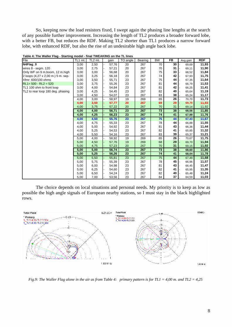
So, keeping now the load resistors fixed, I swept again the phasing line lengths at the search of any possible further improvement. Increasing the length of TL2 produces a broader forward lobe, with a better FB, but reduces the RDF. Making TL2 shorter than TL1 produces a narrow forward lobe, with enhanced RDF, but also the rise of an undesirable high angle back lobe. Table 4: The Waller Flag - Starting model - final TWEAKING on the TL lines File TL1 mt. TL2 mt. gain TO angle Bearing BW FB Avg.gain RDFN4Flag_0 3,00 2,50 57,76- 20 267 70 30 69,69- 11,93 wires 8 - segm. 120 3,00 2,75 57,21- 20 267 70 31 69,11- 11,90 Only WF on 9 m.boom, 12 m.high 3,00 3,00 56,68- 20 267 75 33 68,52- 11,84 2 loops (4,27 x 2,00 m.) 5 m. sep. 3,00 3,25 56,18- 23 267 74 42 67,93- 11,75 Xfmr: 600/100 ohms 3,00 3,50 55,71- 23 267 75 44 67,35- 11,64 RL1= 500 - RL2 = 520 3,00 3,75 55,26- 23 267 81 44 66,79- 11,53 TL1 100 ohm to front loop 3,00 4,00 54,84- 23 267 81 42 66,25- 11,41 TL2 to rear loop 180 deg. phasing 3,00 4,25 54,45- 23 267 82 40 65,64- 11,19
3,00 4,50 54,07- 23 267 83 38 65,24- 11,17 4,00 3,00 58,97- 19 269 65 26 70,70- 11,73 4,00 3,50 57,77- 20 267 69 29 69,70- 11,93 4,00 3,75 57,22- 20 267 70 31 69,14- 11,92 4,00 4,00 56,71- 23 267 73 38 68,56- 11,85 4,00 4,25 56,23- 23 267 74 41 67,99- 11,76 4,00 4,50 55,76- 23 267 75 44 67,43- 11,67 4,00 4,75 55,33- 23 267 78 44 66,88- 11,55 4,00 5,00 54,92- 23 267 81 43 66,36- 11,44 4,00 5,25 54,53- 23 267 82 41 65,85- 11,32 4,00 5,50 54,16- 23 267 83 39 65,37- 11,21 5,00 4,00 58,92- 19 269 65 26 70,67- 11,75 5,00 4,50 57,76- 19 269 68 29 69,70- 11,94 5,00 4,75 57,23- 20 267 70 31 69,15- 11,92 5,00 5,00 56,74- 23 267 73 38 68,60- 11,86 5,00 5,25 56,26- 23 267 74 41 68,04- 11,78 5,00 5,50 55,81- 23 267 75 44 67,49- 11,68 5,00 5,75 55,39- 23 267 78 45 66,96- 11,57 5,00 6,00 54,98- 23 267 81 43 66,45- 11,47 5,00 6,25 54,60- 23 267 82 41 65,95- 11,35 5,00 6,50 54,24- 23 267 82 40 65,48- 11,24 5,00 7,00 53,56- 23 267 84 37 64,59- 11,03
The choice depends on local situations and personal needs. My priority is to keep as low as possible the high angle signals of European nearby stations, so I must stay in the black highlighted rows.
Fig.9: The Waller Flag alone in the air as from Table 4: primary pattern is for TL1 = 4,00 m. and TL2 = 4,25
9
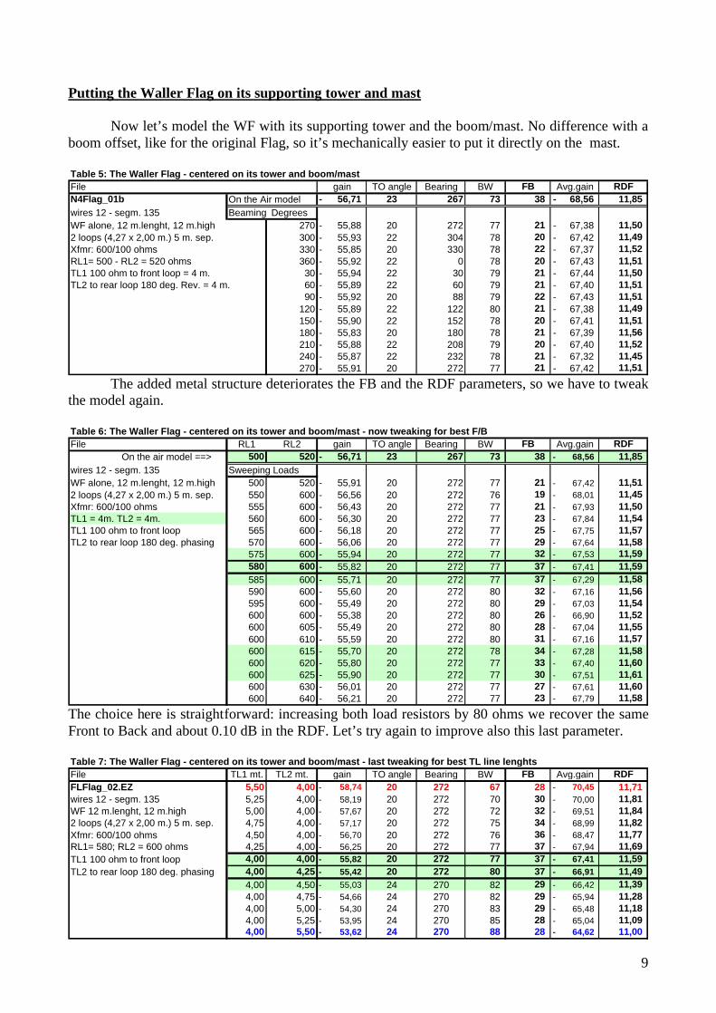
Putting the Waller Flag on its supporting tower and mast Now let’s model the WF with its supporting tower and the boom/mast. No difference with a boom offset, like for the original Flag, so it’s mechanically easier to put it directly on the mast. Table 5: The Waller Flag - centered on its tower and boom/mast File gain TO angle Bearing BW FB Avg.gain RDFN4Flag_01b On the Air model 56,71- 23 267 73 38 68,56- 11,85 wires 12 - segm. 135 Beaming DegreesWF alone, 12 m.lenght, 12 m.high 270 55,88- 20 272 77 21 67,38- 11,50 2 loops (4,27 x 2,00 m.) 5 m. sep. 300 55,93- 22 304 78 20 67,42- 11,49 Xfmr: 600/100 ohms 330 55,85- 20 330 78 22 67,37- 11,52 RL1= 500 - RL2 = 520 ohms 360 55,92- 22 0 78 20 67,43- 11,51 TL1 100 ohm to front loop = 4 m. 30 55,94- 22 30 79 21 67,44- 11,50 TL2 to rear loop 180 deg. Rev. = 4 m. 60 55,89- 22 60 79 21 67,40- 11,51
90 55,92- 20 88 79 22 67,43- 11,51 120 55,89- 22 122 80 21 67,38- 11,49 150 55,90- 22 152 78 20 67,41- 11,51 180 55,83- 20 180 78 21 67,39- 11,56 210 55,88- 22 208 79 20 67,40- 11,52 240 55,87- 22 232 78 21 67,32- 11,45 270 55,91- 20 272 77 21 67,42- 11,51
The added metal structure deteriorates the FB and the RDF parameters, so we have to tweak the model again. Table 6: The Waller Flag - centered on its tower and boom/mast - now tweaking for best F/BFile RL1 RL2 gain TO angle Bearing BW FB Avg.gain RDF On the air model ==> 500 520 56,71- 23 267 73 38 68,56- 11,85 wires 12 - segm. 135 Sweeping LoadsWF alone, 12 m.lenght, 12 m.high 500 520 55,91- 20 272 77 21 67,42- 11,51 2 loops (4,27 x 2,00 m.) 5 m. sep. 550 600 56,56- 20 272 76 19 68,01- 11,45 Xfmr: 600/100 ohms 555 600 56,43- 20 272 77 21 67,93- 11,50 TL1 = 4m. TL2 = 4m. 560 600 56,30- 20 272 77 23 67,84- 11,54 TL1 100 ohm to front loop 565 600 56,18- 20 272 77 25 67,75- 11,57 TL2 to rear loop 180 deg. phasing 570 600 56,06- 20 272 77 29 67,64- 11,58
575 600 55,94- 20 272 77 32 67,53- 11,59 580 600 55,82- 20 272 77 37 67,41- 11,59 585 600 55,71- 20 272 77 37 67,29- 11,58 590 600 55,60- 20 272 80 32 67,16- 11,56 595 600 55,49- 20 272 80 29 67,03- 11,54 600 600 55,38- 20 272 80 26 66,90- 11,52 600 605 55,49- 20 272 80 28 67,04- 11,55 600 610 55,59- 20 272 80 31 67,16- 11,57 600 615 55,70- 20 272 78 34 67,28- 11,58 600 620 55,80- 20 272 77 33 67,40- 11,60 600 625 55,90- 20 272 77 30 67,51- 11,61 600 630 56,01- 20 272 77 27 67,61- 11,60 600 640 56,21- 20 272 77 23 67,79- 11,58
The choice here is straightforward: increasing both load resistors by 80 ohms we recover the same Front to Back and about 0.10 dB in the RDF. Let’s try again to improve also this last parameter. Table 7: The Waller Flag - centered on its tower and boom/mast - last tweaking for best TL line lenghtsFile TL1 mt. TL2 mt. gain TO angle Bearing BW FB Avg.gain RDFFLFlag_02.EZ 5,50 4,00 58,74- 20 272 67 28 70,45- 11,71 wires 12 - segm. 135 5,25 4,00 58,19- 20 272 70 30 70,00- 11,81 WF 12 m.lenght, 12 m.high 5,00 4,00 57,67- 20 272 72 32 69,51- 11,84 2 loops (4,27 x 2,00 m.) 5 m. sep. 4,75 4,00 57,17- 20 272 75 34 68,99- 11,82 Xfmr: 600/100 ohms 4,50 4,00 56,70- 20 272 76 36 68,47- 11,77 RL1= 580; RL2 = 600 ohms 4,25 4,00 56,25- 20 272 77 37 67,94- 11,69 TL1 100 ohm to front loop 4,00 4,00 55,82- 20 272 77 37 67,41- 11,59 TL2 to rear loop 180 deg. phasing 4,00 4,25 55,42- 20 272 80 37 66,91- 11,49
4,00 4,50 55,03- 24 270 82 29 66,42- 11,39 4,00 4,75 54,66- 24 270 82 29 65,94- 11,28 4,00 5,00 54,30- 24 270 83 29 65,48- 11,18 4,00 5,25 53,95- 24 270 85 28 65,04- 11,09 4,00 5,50 53,62- 24 270 88 28 64,62- 11,00
10
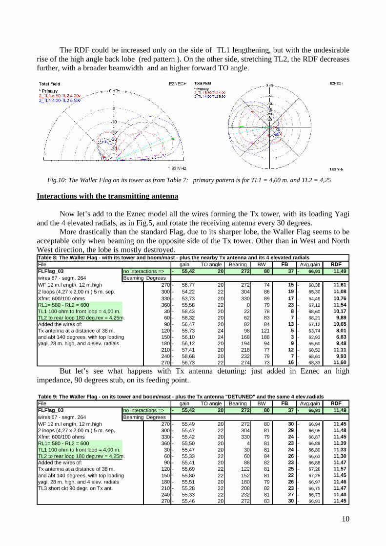
The RDF could be increased only on the side of TL1 lengthening, but with the undesirable rise of the high angle back lobe (red pattern ). On the other side, stretching TL2, the RDF decreases further, with a broader beamwidth and an higher forward TO angle.
Interactions with the transmitting antenna Now let’s add to the Eznec model all the wires forming the Tx tower, with its loading Yagi and the 4 elevated radials, as in Fig.5, and rotate the receiving antenna every 30 degrees.
More drastically than the standard Flag, due to its sharper lobe, the Waller Flag seems to be acceptable only when beaming on the opposite side of the Tx tower. Other than in West and North West direction, the lobe is mostly destroyed. Table 8: The Waller Flag - with its tower and boom/mast - plus the nearby Tx antenna and its 4 elevated radialsFile gain TO angle Bearing BW FB Avg.gain RDFFLFlag_03 no interactions => 55,42- 20 272 80 37 66,91- 11,49 wires 67 - segm. 264 Beaming DegreesWF 12 m.l ength, 12 m.high 270 56,77- 20 272 74 15 68,38- 11,61 2 loops (4,27 x 2,00 m.) 5 m. sep. 300 54,22- 22 304 86 19 65,30- 11,08 Xfmr: 600/100 ohms 330 53,73- 20 330 89 17 64,49- 10,76 RL1= 580 - RL2 = 600 360 55,58- 22 0 79 23 67,12- 11,54 TL1 100 ohm to front loop = 4,00 m. 30 58,43- 20 22 78 8 68,60- 10,17 TL2 to rear loop 180 deg.rev = 4,25m. 60 58,32- 20 62 83 7 68,21- 9,89 Added the wires of: 90 56,47- 20 82 84 13 67,12- 10,65 Tx antenna at a distance of 38 m. 120 55,73- 24 98 121 5 63,74- 8,01 and abt 140 degrees, with top loading 150 56,10- 24 168 188 3 62,93- 6,83 yagi, 28 m. high, and 4 elev. radials 180 56,12- 20 194 94 9 65,60- 9,48
210 57,41- 20 218 77 12 68,52- 11,11 240 58,68- 20 232 79 7 68,61- 9,93 270 56,73- 22 274 73 16 68,33- 11,60
But let’s see what happens with Tx antenna detuning: just added in Eznec an high impedance, 90 degrees stub, on its feeding point. Table 9: The Waller Flag - on its tower and boom/mast - plus the Tx antenna "DETUNED" and the same 4 elev.radialsFile gain TO angle Bearing BW FB Avg.gain RDFFLFlag_03 no interactions => 55,42- 20 272 80 37 66,91- 11,49 wires 67 - segm. 264 Beaming DegreesWF 12 m.l ength, 12 m.high 270 55,49- 20 272 80 30 66,94- 11,45 2 loops (4,27 x 2,00 m.) 5 m. sep. 300 55,47- 22 304 81 29 66,95- 11,48 Xfmr: 600/100 ohms 330 55,42- 20 330 79 24 66,87- 11,45 RL1= 580 - RL2 = 600 360 55,50- 20 4 81 23 66,89- 11,39 TL1 100 ohm to front loop = 4,00 m. 30 55,47- 20 30 81 24 66,80- 11,33 TL2 to rear loop 180 deg.rev = 4,25m. 60 55,33- 22 60 84 26 66,63- 11,30 Added the wires of: 90 55,41- 20 88 82 23 66,88- 11,47 Tx antenna at a distance of 38 m. 120 55,69- 22 122 81 25 67,26- 11,57 and abt 140 degrees, with top loading 150 55,80- 22 152 81 22 67,25- 11,45 yagi, 28 m. high, and 4 elev. radials 180 55,51- 20 180 79 26 66,97- 11,46 TL3 short ckt 90 degr. on Tx ant. 210 55,28- 22 208 82 23 66,75- 11,47
240 55,33- 22 232 81 27 66,73- 11,40 270 55,46- 20 272 83 30 66,91- 11,45
Fig.10: The Waller Flag on its tower as from Table 7: primary pattern is for TL1 = 4,00 m. and TL2 = 4,25
11
The Waller Flag in the IV3PRK environmentFront/Back dB variations vs. Flag bearing degrees
-5
10152025303540
270
330 30 90 150
21027
0
Tx ant.detuned - 32ground radials
Tx ant.detuned - 4elev.radialsTx antenna with 4elev.radials
The Waller Flag in the IV3PRK environmentRDF dB variations vs. Flag bearing degrees
6,00
7,00
8,00
9,00
10,00
11,00
12,00
27033
0 30 90 150
210
270
Tx ant.detuned - 32ground radialsTx ant.detuned - 4elev.radialsTx antenna with 4elev.radials
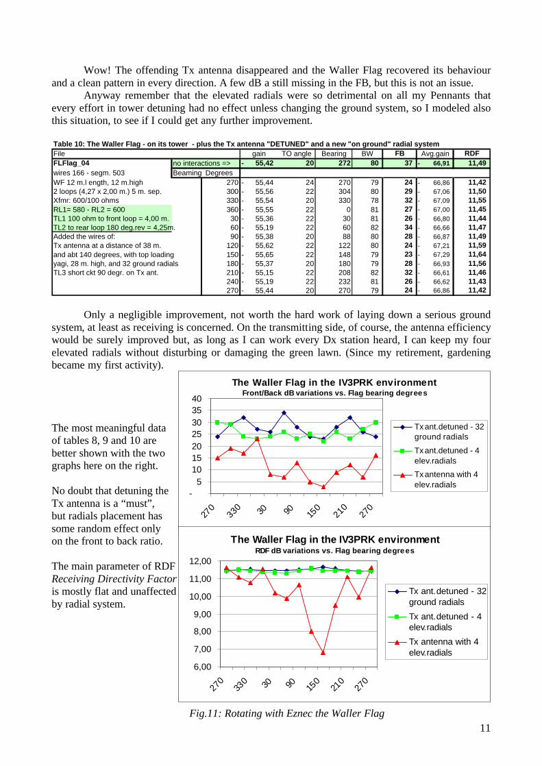
Wow! The offending Tx antenna disappeared and the Waller Flag recovered its behaviour and a clean pattern in every direction. A few dB a still missing in the FB, but this is not an issue. Anyway remember that the elevated radials were so detrimental on all my Pennants that every effort in tower detuning had no effect unless changing the ground system, so I modeled also this situation, to see if I could get any further improvement. Table 10: The Waller Flag - on its tower - plus the Tx antenna "DETUNED" and a new "on ground" radial systemFile gain TO angle Bearing BW FB Avg.gain RDFFLFlag_04 no interactions => 55,42- 20 272 80 37 66,91- 11,49 wires 166 - segm. 503 Beaming DegreesWF 12 m.l ength, 12 m.high 270 55,44- 24 270 79 24 66,86- 11,42 2 loops (4,27 x 2,00 m.) 5 m. sep. 300 55,56- 22 304 80 29 67,06- 11,50 Xfmr: 600/100 ohms 330 55,54- 20 330 78 32 67,09- 11,55 RL1= 580 - RL2 = 600 360 55,55- 22 0 81 27 67,00- 11,45 TL1 100 ohm to front loop = 4,00 m. 30 55,36- 22 30 81 26 66,80- 11,44 TL2 to rear loop 180 deg.rev = 4,25m. 60 55,19- 22 60 82 34 66,66- 11,47 Added the wires of: 90 55,38- 20 88 80 28 66,87- 11,49 Tx antenna at a distance of 38 m. 120 55,62- 22 122 80 24 67,21- 11,59 and abt 140 degrees, with top loading 150 55,65- 22 148 79 23 67,29- 11,64 yagi, 28 m. high, and 32 ground radials 180 55,37- 20 180 79 28 66,93- 11,56 TL3 short ckt 90 degr. on Tx ant. 210 55,15- 22 208 82 32 66,61- 11,46
240 55,19- 22 232 81 26 66,62- 11,43 270 55,44- 20 270 79 24 66,86- 11,42
Only a negligible improvement, not worth the hard work of laying down a serious ground system, at least as receiving is concerned. On the transmitting side, of course, the antenna efficiency would be surely improved but, as long as I can work every Dx station heard, I can keep my four elevated radials without disturbing or damaging the green lawn. (Since my retirement, gardening became my first activity). The most meaningful data of tables 8, 9 and 10 are better shown with the two graphs here on the right. No doubt that detuning the Tx antenna is a “must”, but radials placement has some random effect only on the front to back ratio. The main parameter of RDF Receiving Directivity Factor is mostly flat and unaffected by radial system.
Fig.11: Rotating with Eznec the Waller Flag
12
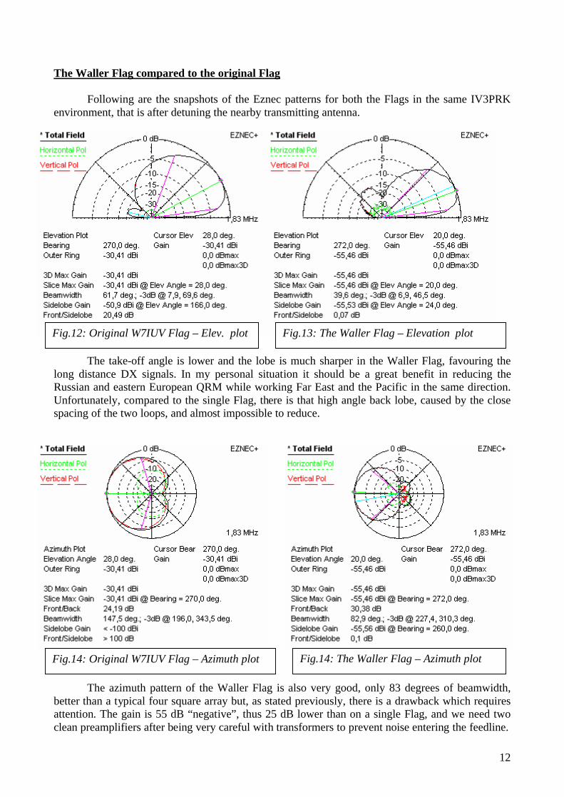
The Waller Flag compared to the original Flag Following are the snapshots of the Eznec patterns for both the Flags in the same IV3PRK environment, that is after detuning the nearby transmitting antenna.
The take-off angle is lower and the lobe is much sharper in the Waller Flag, favouring the long distance DX signals. In my personal situation it should be a great benefit in reducing the Russian and eastern European QRM while working Far East and the Pacific in the same direction. Unfortunately, compared to the single Flag, there is that high angle back lobe, caused by the close spacing of the two loops, and almost impossible to reduce. The azimuth pattern of the Waller Flag is also very good, only 83 degrees of beamwidth, better than a typical four square array but, as stated previously, there is a drawback which requires attention. The gain is 55 dB “negative”, thus 25 dB lower than on a single Flag, and we need two clean preamplifiers after being very careful with transformers to prevent noise entering the feedline.
Fig.12: Original W7IUV Flag – Elev. plot Fig.13: The Waller Flag – Elevation plot
Fig.14: Original W7IUV Flag – Azimuth plot Fig.14: The Waller Flag – Azimuth plot
13
Upgrading to the Waller Flag at IV3PRKFB after detuning the TX antenna with 4 elevated radials
-5
10152025303540
270
330 30 90 15
021
027
0
Waller FlagOriginal Flag
Upgrading to the Waller Flag at IV3PRKRDF after detuning the TX antenna with 4 elevated radials
6
7
8
9
10
11
12
270
330 30 90 15
021
027
0
Waller FlagOriginal Flag
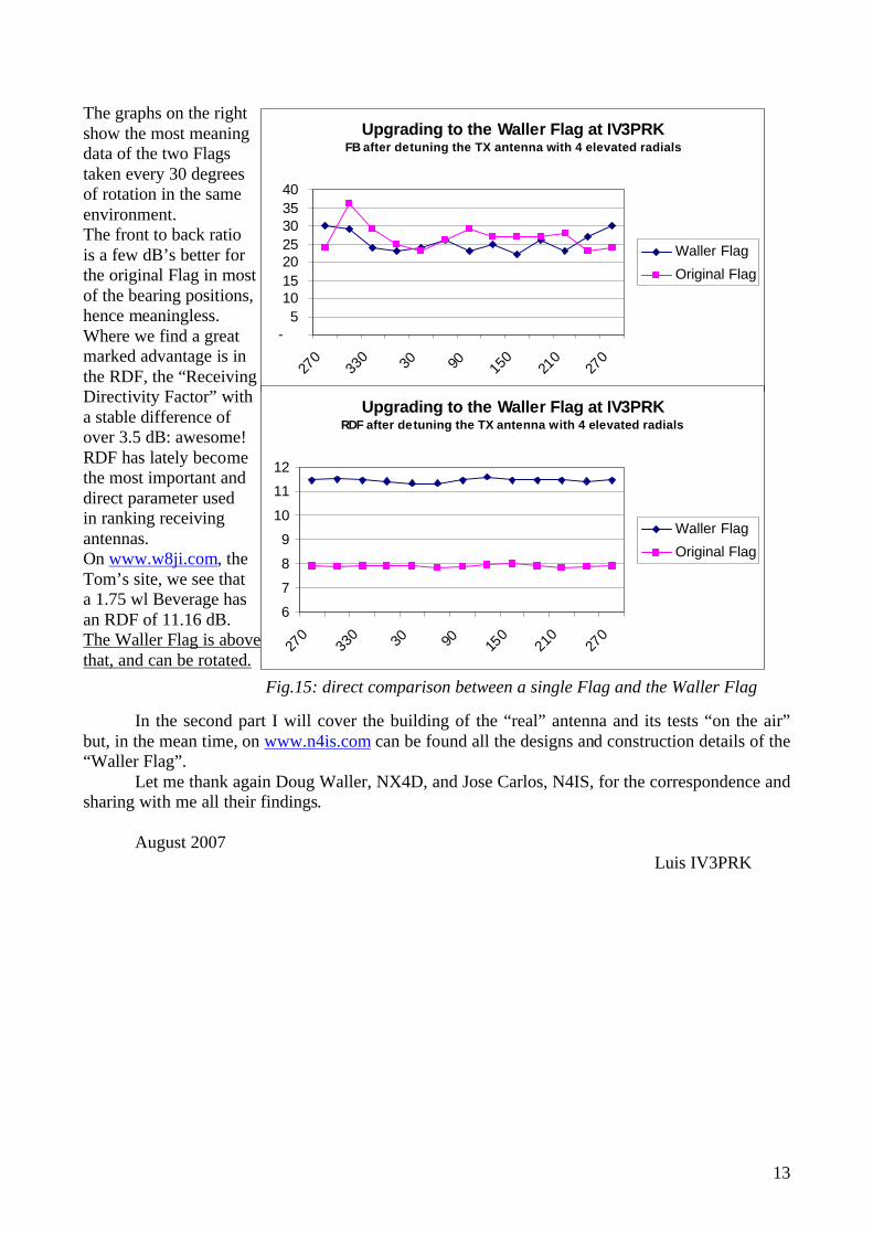
The graphs on the right show the most meaning data of the two Flags taken every 30 degrees of rotation in the same environment. The front to back ratio is a few dB’s better for the original Flag in most of the bearing positions, hence meaningless. Where we find a great marked advantage is in the RDF, the “Receiving Directivity Factor” with a stable difference of over 3.5 dB: awesome! RDF has lately become the most important and direct parameter used in ranking receiving antennas. On www.w8ji.com, the Tom’s site, we see that a 1.75 wl Beverage has an RDF of 11.16 dB. The Waller Flag is above that, and can be rotated. In the second part I will cover the building of the “real” antenna and its tests “on the air” but, in the mean time, on www.n4is.com can be found all the designs and construction details of the “Waller Flag”.
Let me thank again Doug Waller, NX4D, and Jose Carlos, N4IS, for the correspondence and sharing with me all their findings.
August 2007 Luis IV3PRK
Fig.15: direct comparison between a single Flag and the Waller Flag