Embed Size (px)
Citation preview

1
FIRST SILICON FUNCTIONA VALIDATION AND DEBUG OF MULTICORE MICRPROCESSORS
Todd J. Foster, Dennis L. Lastor, and Padmaraj Singh
Presented By Yevgeny FridlyandECGR 6185- Advanced Embedded Systems

PROBLEM
2
Deeply pipelined, multi-core super-scalar processors with multiple levels of cache, connected together through
HyperTransport bus presents unique challenges in the silicon debug laboratory
3
Microprocessor debug features and their use in debugging functional failures
Overview of microprocessor's first silicon validation
Method to validate and debug intra-node and inter-node communication traffic.
Determine optimal on die debug resources
Demonstrate the extent of intrusiveness of a coherent and non-coherent traffic debug feature
OVERVIEW
4
Microprocessor Debug Features
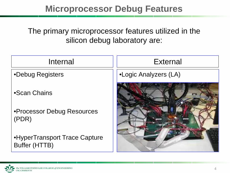
Internal•Debug Registers
•Scan Chains
•Processor Debug Resources (PDR)
•HyperTransport Trace Capture Buffer (HTTB)
External
The primary microprocessor features utilized in the silicon debug laboratory are:
•Logic Analyzers (LA)

Microprocessor Debug Features
Debug Register –
Used to insert and coordinate breakpoints in the program.
Breakpoints may be set on matches to instruction address, data address, or I/O address.
Scan Chains –
A design for test (DFT) feature.
Processor state is captured at a specific clock cycle and the contents of each latch in the scan chain are serially shifted out through the test access port (TAP).
5
Microprocessor Debug Features
HyperTransport Trace Capture Buffer (HTTB)-
- Captures information about the HyperTransport traffic flowing through the microprocessor’s NM.
- The NB’s traffic router crossbar (XBAR) connects the HyperTranport links to the remaining NB components.
- HTTB snoops XBAR command and data buses to capture HyperTransport packets & has access to all traffic flowing through the primary NB blocks.
These debug resources are the basic components that help create the foundations for effective debug of microprocessors
6
7
Debugging Functional Failures
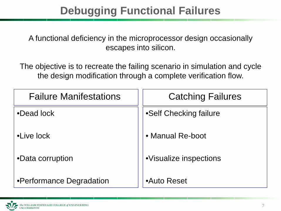
Failure Manifestations
•Dead lock
•Live lock
•Data corruption
•Performance Degradation
Catching Failures
•Self Checking failure
• Manual Re-boot
•Visualize inspections
•Auto Reset
A functional deficiency in the microprocessor design occasionally escapes into silicon.
The objective is to recreate the failing scenario in simulation and cycle the design modification through a complete verification flow.
Debugging Functional Failures - Examples
8
Dead lock – Negligible activity is observed with the core, buses or peripheral devices. The core is not retiring instructions.
- Reset is generally the only means to bring the system out of dead lock.
- enabling HTTB for narrow but successive windows before dead lock provides a glimpse into activity within the NB.
Live lock – freezes the system but the core continues to retire instructions. The program will not make forward progress because of some system conflict.
- A self-checking MP test can provide a glimpse into the failure

Microprocessor's First Silicon Validation
9
Once silicon arrives in the validation laboratory, enormous effort goes into making a microprocessor production ready.
There are three validation stages:
1. Initial Validation Stage
2. Intermediate Validation Stage
3. Final Validation Stage
Microprocessor’s First Silicon Validation
10
Initial Validation Stage:
Initially, the validation process focuses on rudimentary diagnostics and on booting selected operating systems (OS). The microprocessor is validated for functionality and compatibility.
• Booting selected versions of Windows OS
• Booting selected versions of Linux OS
• Duel booting selected versions of Windows OS
• Duel booting Linux & Windows OS
• Duel booting selected versions of Linux OS
Microprocessor’s First Silicon Validation
11
Intermediate Validation Stage:
The microprocessor is tested for compatibility on numerous platforms created by multiple vendors.
All major OS and applications from all market segments are extensively run on multiple platforms. Programs utilizing heavy graphics and memory usage are run for long durations of time.
Numerous Chip-sets, device drivers, and BIOS are tested for compatibility issues. Specialize BIOS help compress the time to failure during the validation process.

Microprocessor’s First Silicon Validation
12
At this stage problems related to software and platform compatibility have been minimized and the possibility of uni-processor failures have been greatly reduced.
Problems related to memory consistency, memory ordering, cache coherency and atomicity are rigorously tested.
Server applications and random code generators are run for much longer periods.
Final Validation Stage:
Method to Validate and Debug Intra-Node and Inter-Node Communication Traffic.
13
HyperTransport Technology (HTT) is a packet-based point-to-point bus. Its characteristics include clock forwarding and differential signaling and
allows commands to be inserted in data streams and also allows asymmetric upstream/downstream link width and frequency.
!Remember!The HTTB captures packets flowing through the XBAR. The XBAR sits between the HT links and remaining NB components giving the HTTB
access to all intra-node HT traffic.
HyperTransport Technology Trace and Capture Analysis
Method to Validate and Debug Intra-Node and Inter-Node Communication Traffic.
14
Current AMD processors contain up to three HyperTransport links. Each link is configurable as either coherent or non-coherent.
- Coherent links provide interface between the processors’ coherent domains.
- Non-coherent protocol is for attaching I/O
The inter-core (intra-node) and inter-node communication occurs by sending and receiving transactions on the HyperTransport bus.
15
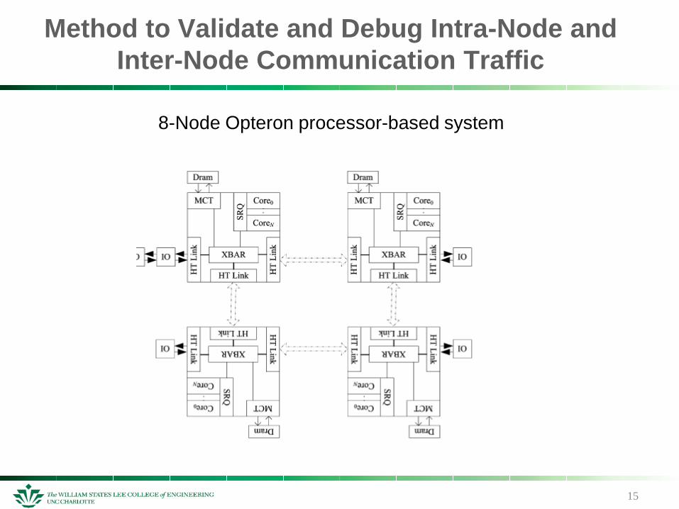
8-Node Opteron processor-based system
Method to Validate and Debug Intra-Node and Inter-Node Communication Traffic

16
How HTTB works: CPU READ to local DRAM with probe miss
Method to Validate and Debug Intra-Node and Inter-Node Communication Traffic.
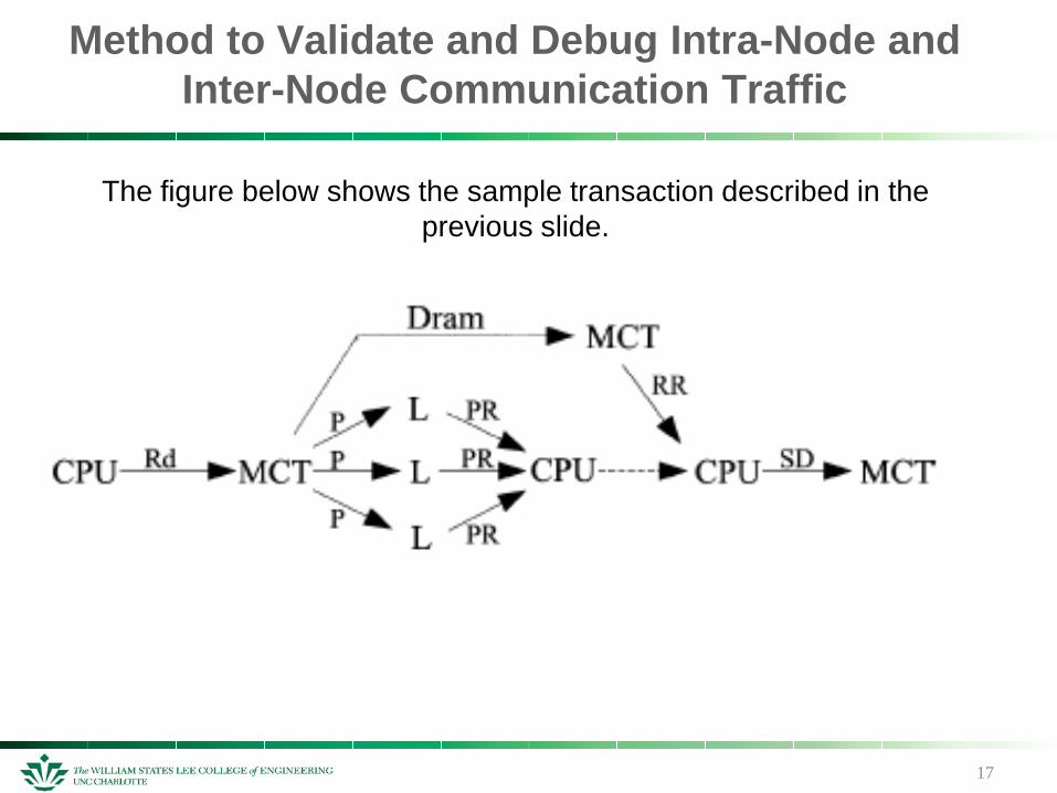
1. CPU sends a READ (rd) request to the MCT
2. The MCT issues a READ to DRAM and sends probe (P) on the HyperTansport links (L) to all coherent nodes
3. CPU Waits for probe responses (PR) from nodes & READ responses (RR) from the MCT
4. Once received CPU responds with source done (SD) to the MCT. This completes the transaction
The HTTB may be programmed to capture all packets related to specific transaction types.
17
The figure below shows the sample transaction described in the previous slide.
Method to Validate and Debug Intra-Node and Inter-Node Communication Traffic
18
How Capture Analysis works: Using the Logic Analyzer
Method to Validate and Debug Intra-Node and Inter-Node Communication Traffic.
The LA captures inter-node HyperTransport (HT) packets through physical probes attached onto MP system motherboard.
A decoder interprets the differential singals to translate the data into HT packets
The LA is equipped to gather and store inter-node HT trafic for extended runs.
19
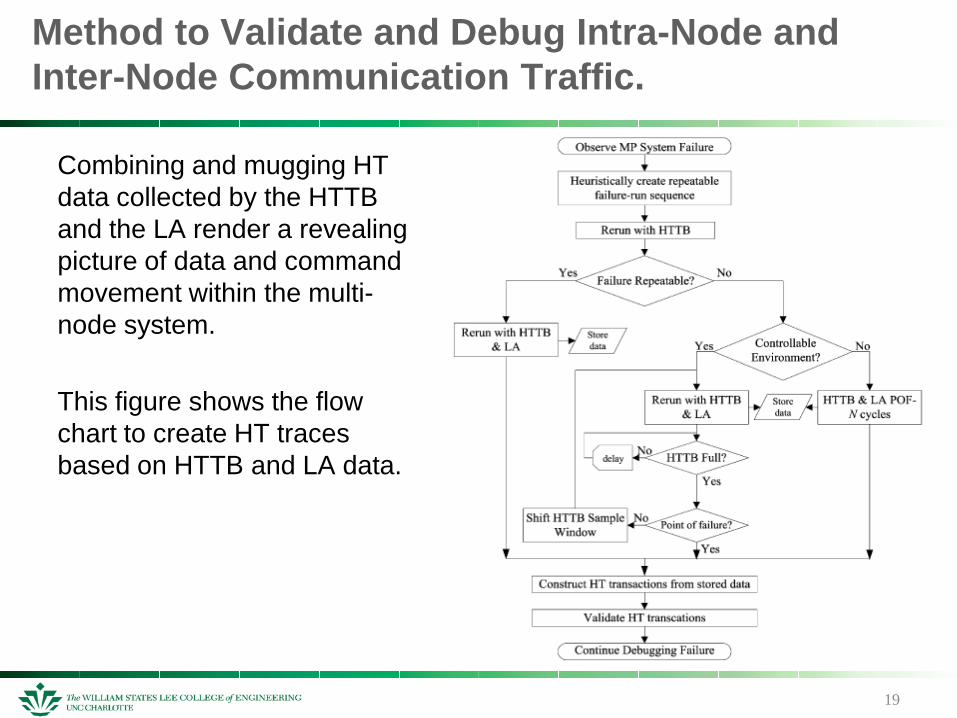
Combining and mugging HT data collected by the HTTB and the LA render a revealing picture of data and command movement within the multi-node system.
This figure shows the flow chart to create HT traces based on HTTB and LA data.
Method to Validate and Debug Intra-Node and Inter-Node Communication Traffic.
Determine Optimal On Die Debug Resources
20
Given the significance of HT trace analysis in MP system validation and debug, selecting the appropriate HTTB size is crucial. Silicon real estate is EXPENSIVE
The node with greatest HT packet flow rate will provide the profile to determine HTTB size.
Optimal HTTB size is computed based on the projected maximum number of packets it will need to hold for a typical MP failure.
Once HTTB fills up and begins emptying its contents into the DRAM, it will stall the XBAR and could cause a failing program to stop failing or visa versa.
Determine Optimal On Die Debug Resources
21
Current AMD processors contain up to three HT links. Each link is configurable as either coherent or non coherent.
The coherent HT links provide interface between processors’ coherent domains.
Non-coherent HT protocol is for attaching I/O
The inter-core (intra-node) and inter-node communication occurs by sending and receiving transactions on the HT bus.
Demonstrate the Extent of Intrusiveness of a Coherent and Non-Coherent Traffic Debug Feature
22
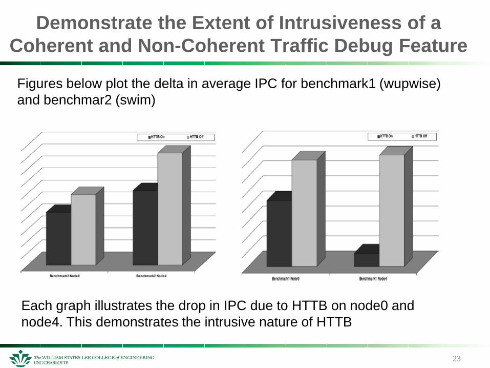
When the HTTB fills up and has to dump to DRAM it becomes very intrusive. To be nonintrusive, all intra-node HT traffic of interest should fit into the HTTB. HTTB may be selectively disabled on nodes where the IPC delta is the greatest.
Benchmarks were run on an 8-node AMD Opteron processor system
Node0Connected to two coherent HT links and to a single non-coherent HT link
Node4 Embedded within the HT fabric and connects to three coherent HT links
23
Demonstrate the Extent of Intrusiveness of a Coherent and Non-Coherent Traffic Debug Feature
Each graph illustrates the drop in IPC due to HTTB on node0 and node4. This demonstrates the intrusive nature of HTTB
Figures below plot the delta in average IPC for benchmark1 (wupwise) and benchmar2 (swim)
CONCLUSION
24
HTTB is highly intrusive and can cause great delays in validating a new microprocessor. This report presents a solution to this problem by creating a streamlined way of how to determine HTTB size so that HTTB causes less
intrusiveness during validation

QUESTIONS
25


![[Robert B. Ash] Measure, Integration and Functiona(BookFi.org)](https://img.dokumen.tips/doc/110x75/544ce976b1af9f2a198b45b1/robert-b-ash-measure-integration-and-functionabookfiorg.jpg)


