Embed Size (px)
Citation preview

Fire, Smoke, and Combination Fire Smoke
Dampers


Agenda Installation/Configuration
Fire Dampers Smoke Dampers Combination Fire/Smoke Dampers
Operational Test/Inspection Periodic Test/Maintenance

Damper Selection
• Comply with code requirements
• Design for long term use • Modification restrictions

What makes an approved system?
Barrier Product Installation
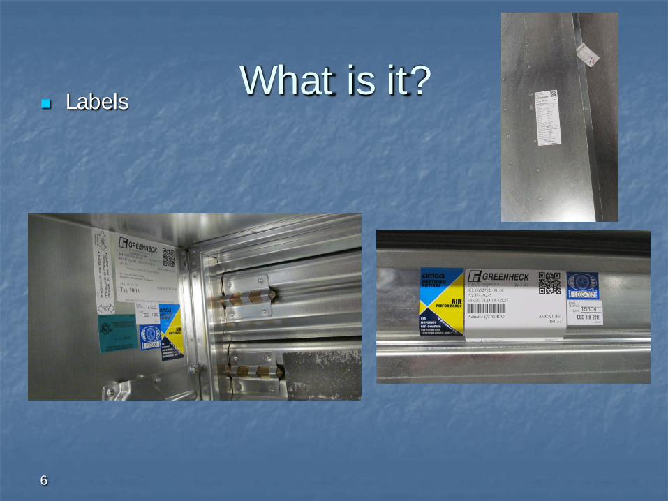
What is it?
6
Labels

Is it right?

UL 555: Fire Dampers

UL 555 Classifications
Static for use in HVAC systems that
shut off in case of a fire emergency
Dynamic for use in HVAC systems that
continue running during a fire emergency
dynamic airflow test increments of 1000 fpm

10
Damper Construction Type
Curtain Multi-blade
Blade Type
Material Galvanized 304 stainless steel 316 stainless steel
Mounting Vertical Horizontal

Damper Ratings
Closure Temperature 165° F (minimum) Operational Temperature (maximum)
Operational Temperature 250° F (minimum) 100° F increments

Damper Ratings
Operational Airflow Rating 2000 fpm 3000 fpm 4000 fpm
Operational Closure Pressure Rating 4 in. wg. 6 in. wg. 8 in. wg.

Combination Fire Smoke & Fire Dampers - Ratings
IBC 717.3.2.1 Fire Protection rating. Fire dampers shall have the minimum
fire protection rating specified in Table for the type of penetration
Type of Penetration Minimum Damper Rating (hours)
Less than 3-hour fire resistance rated assemblies
1.5
3-hour or greater fire resistance rated assemblies
3


15
Fire Damper Selection
System Requirements Dynamic vs Static Temperature Velocity/Pressure Size Mounting

16
Vertical Horizontal
Mounting

17
Fire Damper Selection
Performance Closure Device Controls Free Area Pressure Loss

Transitions
18

Installation Requirements
Fire and Fire Smoke Dampers
Framing of Opening • Vertical studs must run floor to ceiling
• Double vertical studs over 36”x36”
• Wood studs must be covered with sheet rock
• Steel studs do not need to be covered with sheet rock

Fire Damper Installation
Installed with sleeves factory or field mounted sleeve requirements

Installation Requirements
Fire and Fire Smoke Dampers
1. The centerline of the damper frame must be in the plane of the wall/floor
2. Annular Space Requirements
Traditional Installation

Installation Requirements
Fire and Fire Smoke Dampers
3. Retaining Angle Installation
• Angles must be fastened to the sleeve (not to the barrier)
• Attachments 2” from corners then 6” O.C.
• Angles must overlap barrier by at least 1”
• Angles are continuous with no gaps
Traditional Installation

Installation Requirements
Fire and Fire Smoke Dampers
Alternate Installation
1. Single Side Angle
2. 3 Sided Angle
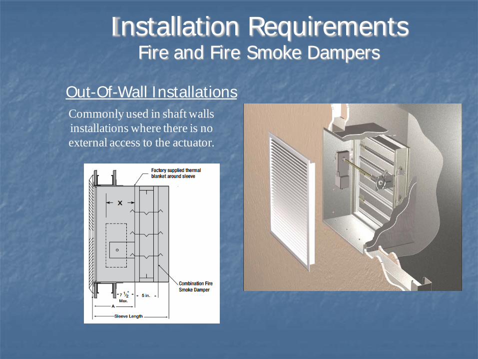
Commonly used in shaft walls installations where there is no external access to the actuator.
Installation Requirements Fire and Fire Smoke Dampers
Out-Of-Wall Installations

Installation Requirements
Fire and Fire Smoke Dampers
4. Duct to Sleeve Connections
• Transverse Joints
• TDC/TDF
• Manufactured Systems
• Rigid Connection (when allowed)
Traditional Installation
Installation Requirements
Fire and Fire Smoke Dampers

Installation Requirements
Access and Identification
Section 716.4 of the IBC
• “Fire and smoke dampers shall be provided with an approved means of access, which is large enough to permit inspection and maintenance of the damper and its operating parts.”
• “Access points shall be permanently identified on the exterior by a label having letters not less than ½” in height reading: Fire/Smoke Damper, Smoke Damper or Fire Damper”
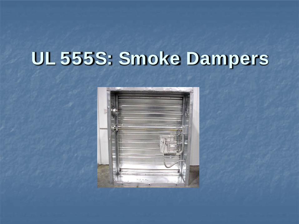
UL 555S: Smoke Dampers

Smoke Damper Construction
Type multi-blade 3-V or airfoil blade
Construction blade and jamb seals always with a UL-
approved actuator

30
Smoke Damper Actuators Mounting
must be factory mounted internal or external
Operation spring return two position or modulating

UL 555S Classifications Leakage Class
I (8 cfm/sq. ft @ 4 in.wg) II (20 cfm/sq. ft @ 4 in.wg) III (80 cfm/sq. ft @ 4 in.wg)
IBC 716.3.2 Smoke damper leakage ratings shall not be less than Class II.
Operational Temperature Maximum operating temperature for damper 250° F 350° F

Amount of Time to Fill a Room with Smoke Based on Leakage Class
Leakage Length of Class Time I = 100 minutes II = 40 minutes III = 10 minutes
20’
20’ 8’
24”x 24” (610mm x 610mm)
Damper

Smoke Damper Installation
Installed in ductwork With sleeve Without sleeve
Location centerline within 24” of the barrier**

Smoke Damper Installation
In Accordance with Manufacturer’s IOMs Sealing Damper
It is acceptable to seal damper frame and duct with approved sealants
Actuator Requirements Wire actuator in compliance with local wiring codes Refer to wiring diagrams for each actuator

Combination Fire/Smoke Dampers

Purpose of Fire/Smoke Damper
Provide the same level of protection as individual fire and smoke dampers
Installation guidelines of fire and smoke dampers apply

Fire Smoke Installation
Actuators UL-certified actuators installed at factory
Operation spring return two position or modulating

Actuator Types Electric
Pneumatic
Manual

Fire/Smoke Damper Closure Devices
Fuse Link Electronic Link
bi-metallic sensor wired in series with actuator cuts power to actuator when
temperature is reached Resettable

Operational Test/Inspection

• Damper installed racked.
Importance of Inspection

• Misaligned jackshaft on damper.
Importance of Inspection

• Actuator in the barrier
Importance of Inspection

• Screw blocking blade
Importance of Inspection

Frequency
“After the installation of a damper is completed, an operational test shall be conducted.”
Test Method
“The damper shall fully close from the open position.” “The operational test shall verify that there is full and unobstructed access to the fire damper and all listed components” “All indicating devices shall be verified to work and report to the intended location” “The operational test shall be conducted under non-fire HVAC airflow conditions as well as static flow conditions”
NFPA 80 Standard for Fire Doors and Other Opening
Protectives
Operational Test

Frequency
“An operational test shall be conducted after the building’s HVAC system has been balanced”
Test Method
“The operational test shall be conducted under normal HVAC airflow conditions as well as static flow conditions. The damper shall fully close/seal under both test conditions” “All indicating devices shall be verified to work properly and report to the intended location” “Combination fire/smoke dampers shall also meet the testing requirements contained in NFPA 80”
NFPA 105 Standard for the Installation of Smoke Door Assemblies and Other Opening Protectives
Operational Test

Period Tests/Maintenance

• Garbage placed inside of damper.
Importance of Maintenance

I-Codes
Periodic Testing Requirements

International Fire Code (IFC)
Smoke Dampers “All openings protected with approved smoke barrier doors or smoke dampers shall be maintained in accordance with NFPA 105
Fire Dampers “All openings protected with approved doors or fire dampers shall be maintained in accordance with NFPA 80
Periodic Testing Requirements

Frequency
“Each damper shall be tested and inspected 1 year after installation” and then “every 4 years, except in hospitals, where the frequency shall be every 6 years”
Test Method
“If the fire damper is equipped with a fusible link, the link shall be removed for testing to ensure full closure” “The operational test of the damper shall verify that there is no damper interference due to rusted, bent, misaligned, or damaged frame or blades”
NFPA 80 Standard for Fire Doors and Other Opening
Protectives
Periodic Testing Requirements
Maintenance
“All exposed moving parts of the damper shall be dry lubricated as required by the manufacturer” “If the damper is not operable, repairs shall begin without delay” “Following any repairs, the damper shall be test for operation in accordance with Section 19.4(Inspection and Testing)
NFPA 80 Standard for Fire Doors and Other Opening
Protectives
Periodic Testing Requirements

Frequency
“Each damper shall be tested and inspected 1 year after installation” and then “every 4 years, except in hospitals, where the frequency shall be every 6 years”
Test Method
“If the fire damper is equipped with a fusible link, the link shall be removed for testing to ensure full closure” “The operational test of he damper shall verify that there is no damper interference due to rusted, bent, misaligned, or damaged frame or blades”
NFPA 105 Standard for the Installation of Smoke Door Assemblies and Other Opening Protectives
Periodic Testing Requirements

NFPA 105 Standard for the Installation of Smoke Door Assemblies and Other Opening Protectives
Maintenance “All exposed moving parts of the damper shall be dry lubricated as required by the manufacturer” “If the damper is not operable, repairs shall begin without delay” “Following any repairs, the damper shall be test for operation in accordance with Section 6.5(Inspection and Testing)
Periodic Testing Requirements

New AMCA Maintenance Guide
Periodic Testing Requirements

Testing Options Position Switches
providing positive blade indication
Control Modules test the operation of damper from a remote location Multiple configurations

Position Indication
On-Blade Built-In to Actuator
Notification Options

Test Stations
Test Switch Toggle Switch
Keyed Switch
Momentary Switch
Lights Only
Test Options

Installation Books

Thank You