Embed Size (px)
Citation preview
Fire Performance Cables
Draka Cableteq Australasia
Contents
01 Company Profile
02 Introduction/Application
03 MAX-FOH
04 Construction of Cable
06 Standards and Approvals
08 Table of Construction
12 Selection Of Cross-sectional Area Of Conductor
14 Handling and installation of FR cable
15 Low Smoke Halogen Free Cables 17 Characteristics of Low Smoke Halogen Free Cables
18 Construction of Cable 20 Table of Construction
25 Tables for MAX-FOH and LSF Cables
26 Current Ratings And Voltage Drop Table (Unarmoured Cable)
32 Current Ratings And Voltage Drop Table (Armoured Cable)
35 Short Circuit Ratings
36 Technical Information

1
Company Profile
Draka Holdings N.V. was first established in 1910 as Draka Kabel B.V.. Currently, our company has 67 operating companies spread out across three continents: Europe, North and South America, and Asia, in 29 countries, providing employment for more than 8,800 people worldwide.
Draka Holdings N.V. consists of two groups namely Draka Comteq, which specializes in communication cables; and Draka Cableteq, which specializes in low-voltage and special purpose cables.
Draka Cableteq The Draka Cableteq group specializes in developing, producing and marketing a range of low-voltage and special-purpose cables for application in premises and for OEM application.
The group consists of six divisions:Low-Voltage Cable, Elevator Cable, Marine, Oil & Gas, Rubber Cable, Mobile Network Cable and Transport.
Our main clientele for these products include electrical wholesalers, construction and installation companies, engineering and procurement companies, lift manufacturers, harness makers for car manufacturers and aerospace industry, shipbuilding, oil and gas industry, domestic and industrial appliance manufacturers and telecommunication companies engaged in mobile telecommunications.
Draka Cableteq Asia Pacific (DCAP)
Draka Cableteq | AustralasiaOur regional headquarters for Australasia, Draka Cableteq’s Australasian operations, reaches out to regional markets in Australia, Brunei, Indonesia, Malaysia, Myanmar, New Zealand, Thailand, and Vietnam.
Currently, Draka Australasia has three manufacturing plants placed strategically in Singapore, Malaysia and Thailand; a sales office in Australia, as well as representative offices in Indonesia and Vietnam.
Singapore Cables Manufacturers Pte Ltd Singapore Cables Manufacturers Pte Ltd (SCM) is a subsidiary of Draka Cableteq Asia Pacific Holdings. SCM first started operations in 1975, and has since grown to be a market leader in Specialty Low-Voltage (Fire Resistant & Flame Retardant, and Instrumentation & Control) and Marine, Oil & Gas cables. Having served numerous companies in Singapore for over three decades, SCM established a strong market presence through a good track record of excellent customer service, reliability, and consistency in delivering products of sterling quality.
2 2
INTRODUCTIONMajor accidents which have resulted in the deaths of many innocent people, have taught us that the safety of the occupants and users in public, commercial and industrial environments is of paramount importance. Every possible safety feature designed to prevent and protect against loss of life and damage to property should be specified and installed.
One such safety feature is the use of fire performance cables for critical safety systems, including fire alarms, emergency lighting, PA systems, CCTV systems, emergency power supplies and smoke & fire shutters.
The correct selection and installation of these “life saving” cables helps ensure that in the event of an emergency, vital safety systems will continue to operate to assist an orderly evacuation of the premises and to aid the emergency services in gaining quick and effective entry to deal with the hazard.
Today’s modern architect is constantly aiming to build higher and larger structures, incorporating complex interiors within which we can both live and work. The construction of these new “super” structures inevitably means accommodating more people, with the added responsibility for their safety and well being resting with the specifiers and consultants responsible for the project.
At Draka, we understand what is required from a fire performance cable and we appreciate the pressures faced by specifiers and consultants in selecting the correct cable form the range available. For nearly twenty years, Draka special cables have been servicing the needs of the market by designing and manufacturing the widest range of fire performance cables available today.
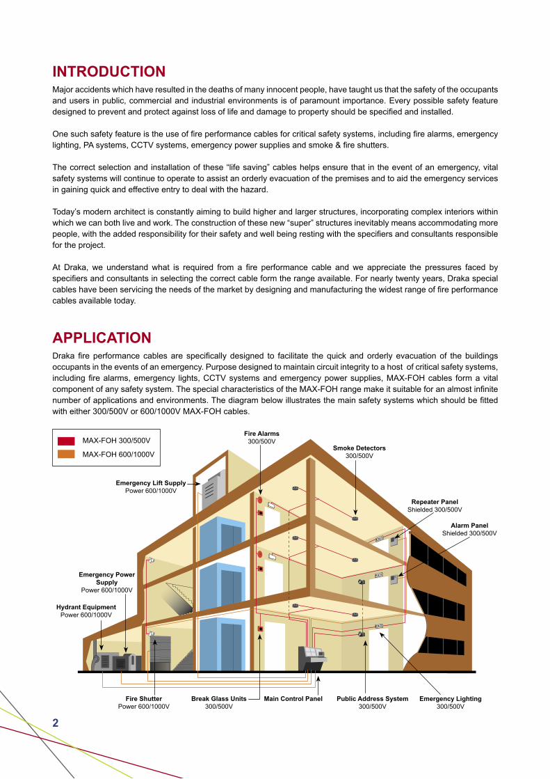
APPLICATIONDraka fire performance cables are specifically designed to facilitate the quick and orderly evacuation of the buildings occupants in the events of an emergency. Purpose designed to maintain circuit integrity to a host of critical safety systems, including fire alarms, emergency lights, CCTV systems and emergency power supplies, MAX-FOH cables form a vital component of any safety system. The special characteristics of the MAX-FOH range make it suitable for an almost infinite number of applications and environments. The diagram below illustrates the main safety systems which should be fitted with either 300/500V or 600/1000V MAX-FOH cables.
MAX-FOH 300/500V
MAX-FOH 600/1000V
Fire Alarms300/500V
Smoke Detectors300/500V
Repeater PanelShielded 300/500V
Alarm PanelShielded 300/500V
Emergency Lift SupplyPower 600/1000V
Emergency Power Supply
Power 600/1000V
Hydrant Equipment Power 600/1000V
Fire ShutterPower 600/1000V
Break Glass Units300/500V
Main Control Panel Public Address System300/500V
Emergency Lighting300/500V
3
MAX-FOH

4 4
CONSTRUCTION OF CABLE
Construction MAX-FOH MAX-FOH-EVA
1 - Conductor Stranded annealed copper
Stranded annealed copper
2 - Fire Barrier Mica tape Mica tape
3 - Insulation Cross-linked polyethylene (XLPE)
Cross-linked EVA **(XLEVA)
4 - Shield* Aluminium foil with tinned copper drain wire
Aluminium foil with tinned copper drain wire
5 - Filler* LSF filler or polypropylene split yarn
LSF filler or polypropylene split yarn
6 - Binder Tape* Polyester tape Polyester tape
7 - Bedding* Low smoke halogen free (LSF) compound (Orange)
Low smoke halogen free (LSF) compound (Orange)
8 - Armour*/# Galvanised steel wire (aluminium or copper wire for single core)
Galvanised steel wire (aluminium or copper wire for single core)
9 - Sheath Low smoke halogen free (LSF) compound (Orange)
Low smoke halogen free (LSF) compound (Orange)
* Optional: Depending on requirement# Braided armour also available on request** XLEVA material used are suitable for operating temperature of up to 125oC
1
2
3
9
1235679
123
456789
Identification of cores:
No. of cores Single Two Three Four Five & above Pairs
ColourNatural or
other colour on request
Red and BlackRed, Yellow
and BlueRed, Yellow,
Blue and Black
Black with white numbering (others on request)
Black with white numbering
Note: Special construction and design to customers’ specification can be provided upon request.
FOUR PAIR
FOUR CORE
SINGLE CORE
5
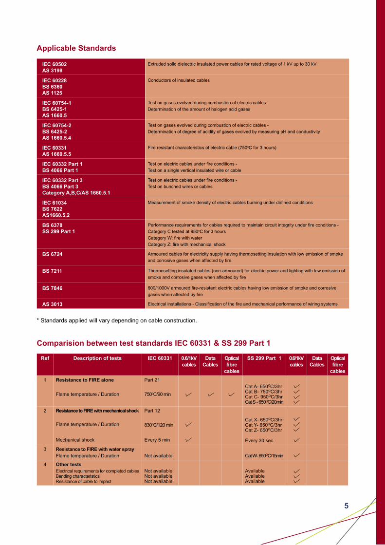
Applicable Standards
IEC 60502AS 3198
Extruded solid dielectric insulated power cables for rated voltage of 1 kV up to 30 kV
IEC 60228BS 6360AS 1125
Conductors of insulated cables
IEC 60754-1BS 6425-1AS 1660.5
Test on gases evolved during combustion of electric cables -
Determination of the amount of halogen acid gases
IEC 60754-2BS 6425-2AS 1660.5.4
Test on gases evolved during combustion of electric cables -
Determination of degree of acidity of gases evolved by measuring pH and conductivity
IEC 60331AS 1660.5.5
Fire resistant characteristics of electric cable (750oC for 3 hours)
IEC 60332 Part 1BS 4066 Part 1
Test on electric cables under fire conditions -
Test on a single vertical insulated wire or cable
IEC 60332 Part 3BS 4066 Part 3Category A,B,C/AS 1660.5.1
Test on electric cables under fire conditions -
Test on bunched wires or cables
IEC 61034BS 7622AS1660.5.2
Measurement of smoke density of electric cables burning under defined conditions
BS 6378SS 299 Part 1
Performance requirements for cables required to maintain circuit integrity under fire conditions -
Category C tested at 950oC for 3 hours
Category W: fire with water
Category Z: fire with mechanical shock
BS 6724 Armoured cables for electricity supply having thermosetting insulation with low emission of smoke
and corrosive gases when affected by fire
BS 7211 Thermosetting insulated cables (non-armoured) for electric power and lighting with low emission of
smoke and corrosive gases when affected by fire
BS 7846 600/1000V armoured fire-resistant electric cables having low emission of smoke and corrosive
gases when affected by fire
AS 3013 Electrical installations - Classification of the fire and mechanical performance of wiring systems
* Standards applied will vary depending on cable construction.
Comparision between test standards IEC 60331 & SS 299 Part 1
Ref Description of tests IEC 60331 0.6/1kVcables
DataCables
Opticalfibre
cables
SS 299 Part 1 0.6/1kVcables
DataCables
Opticalfibre
cables
1 Resistance to FIRE alone
Flame temperature / Duration
Part 21
750oC/90 min
Cat A- 650OC/3hrCat B- 750OC/3hrCat C- 950OC/3hrCat S - 650OC/20min
2 Resistance to FIRE with mechanical shock
Flame temperature / Duration
Mechanical shock
Part 12
830oC/120 min
Every 5 min
Cat X- 650OC/3hrCat Y- 650OC/3hrCat Z- 650OC/3hr
Every 30 sec
3 Resistance to FIRE with water sprayFlame temperature / Duration Not available Cat W- 650OC/15min
4 Other testsElectrical requirements for completed cablesBending characteristicsResistance of cable to impact
Not availableNot availableNot available
AvailableAvailableAvailable

6 6
STANDARDS AND APPROVALS
BS 6387/SS 299: 1994 - Fire, FIre with Water & Fire with Mechanical Shock Tests
The following test is the nationally recognised United Kingdom and Singapore test used to determine if a cable is capable of maintaining circuit integrity under fire conditions, fire with water and fire with mechanical shock. These tests use a number of alternative time and temperature parameters and depending on the level achieved by the cable, a corresponding letter is assigned to denote the category the cable passed.
During the tests the cables are energised at their rated voltage.
MAX-FOH cables meet the highest categories of BS 6387 i.e. C, W & Z.
Resistance to fire: Symbol
650oC for 3 hours A
750oC for 3 hours B
950oC for 3 hours C
950oC for 20 minutes S
Resistance to fire and water: Symbol
650oC for 15 minutes, then for 15 minutes with fire and water W
Resistance to firewith mechanical shock:
Symbol
650oC for 15 minutes,
with 30 second hammer blows X
750oC for 15 minutes, with 30 second hammer blows Y
950oC for 15 minutes, with 30 second hammer blows Z
IEC 61034 - Smoke Density Test
This test measures the smoke emission from electric cables during fire. The test is carried out in a 3m cubed chamber where a cable sample is subjected to fire.
The smoke emission and density are measured by transmitting a beam of light across the inside of the chambers to a photo electric cell which measures the amount of light received.
All MAX-FOH cables comply to IEC 61034 requirements.
3000mm
Fan Flow7m3/min to 13m3/min
PhotocellHeight 2150m
Draught ScreenHeight 1000m
Light SourceHeight 2150m
Door
Burner
7
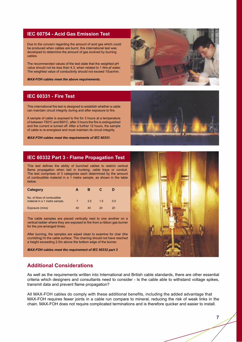
IEC 60754 - Acid Gas Emission Test
Due to the concern regarding the amount of acid gas which could be produced when cables are burnt, this international test was developed to determine the amount of gas evolved by burning cables.
The recommended values of the test state that the weighted pH value should not be less than 4.3, when related to 1 litre of water. The weighted value of conductivity should not exceed 10us/mm.
MAX-FOH cables meet the above requirements.
IEC 60331 - Fire Test
This international fire test is designed to establish whether a cable can maintain circuit integrity during and after exposure to fire.
A sample of cable is exposed to fire for 3 hours at a temperature of between 750oC and 800oC, after 3 hours the fire is extinguished and the current is turned off. After a further 12 hours, the sample of cable is re-energised and must maintain its circuit integrity.
MAX-FOH cables meet the requirements of IEC 60331.
Additional Considerations
As well as the requirements written into International and British cable standards, there are other essential criteria which designers and consultants need to consider - Is the cable able to withstand voltage spikes, transmit data and prevent flame propagation?
All MAX-FOH cables do comply with these additional benefits, including the added advantage that MAX-FOH requires fewer joints in a cable run compare to mineral, reducing the risk of weak links in the chain. MAX-FOH does not require complicated terminations and is therefore quicker and easier to install.
IEC 60332 Part 3 - Flame Propagation Test
This test defines the ability of bunched cables to restrict vertical flame propagation when laid in trunking, cable trays or conduit. The test comprises of 3 categories each determined by the amount of combustible material in a 1 metre sample, as shown in the table below.
Category A B C D No. of litres of combustible material in a 1 metre sample. 7 3.5 1.5 0.5
Exposure (mins) 40 40 20 20
The cable samples are placed vertically next to one another on a vertical ladder where they are exposed to fire from a ribbon gas burner for the pre-arranged times.
After burning, the samples are wiped clean to examine for char (the crumbling) fo the cable surface. The charring should not have reached a height exceeding 2.5m above the bottom edge of the burner.
MAX-FOH cables meet the requirement of IEC 60332 part 3

8 8
TABLE OF CONSTRUCTION
600/1000V, Unarmoured and Armoured Fire Resistant Cables
Table 1
(A) Unarmoured Cables (B) Armoured Cables
Insulated, non-sheathed
Insulated and Sheathed Insulated and Sheathed
Nominalarea of
conductor
Insulation Thickness
Approx.diameteroverall
Approx.weight
Insulation Thickness
SheathThickness
Approx.diameteroverall
Approx.weight
BeddingThickness
Armourwire
diameter
Sheath Thickness
Approx.diameteroverall
Approx.weight
mm2 mm mm kg/km mm mm mm kg/km mm mm mm mm kg/km
Sin
gle
Co
re
1.5 0.7 3.9 32 0.7 1.4 6.4 55 - - - - -
2.5 0.8 4.6 43 0.7 1.4 6.8 70 - - - - -
4 0.8 5.1 55 0.7 1.4 7.4 90 - - - - -
6 0.8 5.6 85 0.7 1.4 7.9 110 - - - - -
10 1.0 7.1 146 0.7 1.4 8.9 160 - - - - -
16 1.0 8.1 198 0.7 1.4 9.9 220 - - - - -
25 1.2 9.8 320 0.9 1.4 12.2 330 - - - - -
35 1.2 10.9 410 0.9 1.4 13.5 430 - - - - -
50 1.4 13.4 549 1.0 1.4 15.0 560 1.0 0.90 1.8 2.0 800
70 1.4 15.2 770 1.1 1.4 17.0 770 1.0 1.25 1.8 22.5 1000
95 1.6 17.6 1140 1.1 1.5 19.0 1040 1.0 1.25 1.8 24.0 1400
120 1.6 19.3 1425 1.2 1.5 20.8 1290 1.0 1.60 1.8 27.0 1700
150 1.8 21.3 1720 1.4 1.6 23.0 1580 1.0 1.60 1.8 29.0 2000
185 2.0 23.7 2155 1.6 1.6 25.3 1950 1.0 1.60 1.9 31.3 2400
240 2.2 26.8 2900 1.7 1.7 28.3 2530 1.0 1.60 2.0 35.0 3300
300 2.4 29.7 3540 1.8 1.8 31.0 3140 1.0 1.60 2.1 37.0 3800
400 2.6 33.3 4410 2.0 1.9 34.7 3970 1.2 2.00 2.3 42.0 4800
500 2.8 37.2 5660 2.2 2.0 38.5 4970 1.2 2.00 2.4 46.0 5900
630 2.8 41.3 7140 2.4 2.2 43.5 6400 1.2 2.00 2.5 51.0 7400
800 - - - 2.6 2.3 48.0 8000 1.4 2.50 2.8 57.0 9400
1000 - - - 2.8 2.4 53.2 10200 1.4 2.50 2.9 62.0 11000
Two
Co
res
1.5 - - - 0.7 1.8 10.4 150 1.0 0.90 1.8 15.0 400
2.5 - - - 0.7 1.8 11.2 180 1.0 0.90 1.8 16.0 450
4 - - - 0.7 1.8 12.3 240 1.0 0.90 1.8 17.0 530
6 - - - 0.7 1.8 13.5 300 1.0 0.90 1.8 18.0 620
10 - - - 0.7 1.8 15.7 420 1.0 1.25 1.8 20.0 900
16 - - - 0.7 1.8 17.8 590 1.0 1.25 1.8 22.0 1050
25 - - - 0.9 1.8 21.2 860 1.0 1.60 1.8 26.5 1600
35 - - - 0.9 1.8 23.7 1120 1.0 1.60 1.9 29.0 1964
A Unarmoured cablesB Armoured cables
A
B

9
600/1000V, Unarmoured and Armoured Fire Resistant Cables
Table 2
(C) Unarmoured Cables (D) Armoured Cables
Nominalarea of
conductor
Insulation Thickness
SheathThickness
Approx.diameteroverall
Approx.weight
BeddingThickness
Armourwire
diameter
Sheath Thickness
Approx.diameteroverall
Approx.weight
mm2 mm mm mm kg/km mm mm mm mm kg/km
Th
ree
Co
res
1.5 0.7 1.8 11.4 170 1.0 0.90 1.8 15.9 450
2.5 0.7 1.8 12.3 215 1.0 0.90 1.8 16.8 510
4 0.7 1.8 13.44 280 1.0 0.90 1.8 18.0 610
6 0.7 1.8 14.7 360 1.0 1.25 1.8 20.0 820
10 0.7 1.8 16.7 510 1.0 1.25 1.8 21.6 1000
16 0.7 1.8 18.5 740 1.0 1.25 1.8 23.8 1300
25 0.9 1.8 22.0 1100 1.0 1.60 1.8 28.0 1900
35 0.9 1.8 25.0 140 1.0 1.60 1.8 31.0 2400
50 1.0 1.8 28.0 1900 1.0 1.60 1.9 34.5 3000
70 1.1 1.9 32.0 2600 1.2 2.00 2.1 40.5 4300
95 1.1 2.0 37.0 3500 1.2 2.00 2.2 45.0 5400
120 1.2 2.1 42.0 4400 1.2 2.00 2.3 49.0 6600
150 1.4 2.4 47.0 5500 1.4 2.50 2.5 55.0 8300
185 1.6 2.4 52.0 6800 1.4 2.50 2.7 60.0 10000
240 1.7 2.6 58.0 8800 1.4 2.50 2.9 67.0 12000
300 1.8 2.7 64.0 10000 1.6 2.50 3.0 74.0 15000
Fo
ur
Co
res
1.5 - 1.8 12.3 200 1.0 0.90 1.8 16.6 500
2.5 - 1.8 13.3 255 1.0 0.90 1.8 17.7 580
4 - 1.8 14.6 335 1.0 1.25 1.8 19.5 800
6 - 1.8 16.0 440 1.0 1.25 1.8 21.0 950
10 - 1.8 18.2 640 1.0 1.25 1.8 23.0 1200
16 - 1.8 21.0 915 1.0 1.60 1.8 26.4 1700
25 - 1.8 25.6 1410 1.0 1.60 1.8 30.5 2300
35 0.9 1.8 28.6 1500 1.0 1.60 1.9 34.2 2900
50 1.0 1.8 32.1 1950 1.0 2.00 2.0 39.0 3900
70 1.1 2.0 37.0 3100 1.2 2.00 2.2 44.0 4900
95 1.1 2.1 42.0 3600 1.2 2.00 2.3 49.0 6600
120 1.2 2.3 47.0 5700 1.4 2.50 2.5 45.0 8500
150 1.4 2.4 51.7 7000 1.4 2.50 2.7 60.0 9900
185 1.6 2.6 57.7 8700 1.4 2.50 2.8 66.0 12000
240 1.7 2.8 65.0 11000 1.6 3.15 3.1 75.0 16000
300 1.8 3.0 71.6 14000 1.6 3.15 3.2 82.0 19000
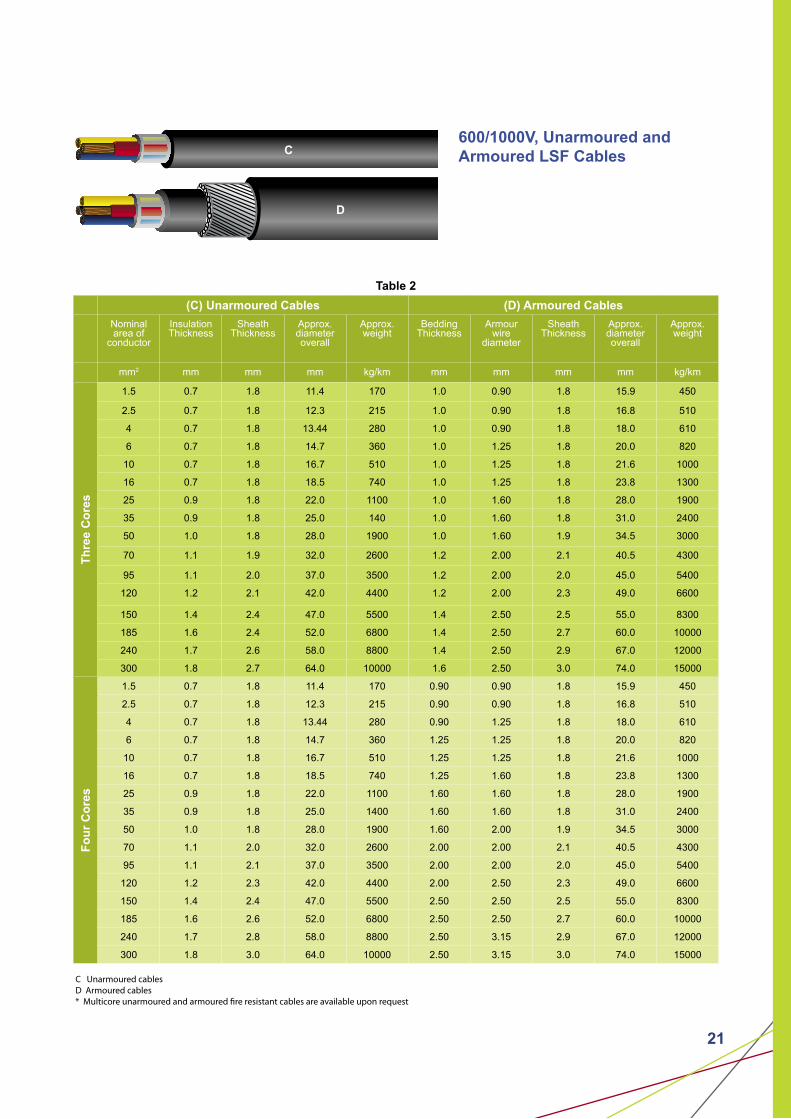
C Unarmoured cablesD Armoured cables* Multicore unarmoured and armoured fire resistant cables are available upon request
C
D

10 10
300/500V, Unarmoured and Armoured Fire Resistant Cables
Table 3
(E) Unarmoured Cables (F) Armoured Cables
Nominalarea of
conductor
No. & Diameter of wires
Insulation Thickness
SheathThickness
Approx.diameteroverall
Approx.weight
BeddingThickness
Armourwire
diameter
Sheath Thickness
Approx.diameteroverall
Approx.weight
mm2 No./mm mm mm mm kg/km mm mm mm mm kg/km
Sin
gle
co
re
0.75 7/0.37 0.55 0.5 4.1 22 0.5 0.9 1.4 8.9 155
1 7/0.44 0.55 0.5 4.3 26 0.5 0.9 1.4 9.1 165
1.5 7/0.53 0.55 0.5 4.6 32 0.5 0.9 1.4 9.4 180
2.5 7/0.67 0.55 0.5 5.0 43 0.5 0.9 1.4 9.8 200
4 7/0.85 0.55 0.5 5.6 60 0.5 0.9 1.4 10.4 240
Two
co
res
0.75 7/0.37 0.55 0.5 7.0 64 0.5 0.9 1.4 11.8 285
1 7/0.44 0.55 0.5 7.4 74 0.5 0.9 1.4 12.2 310
1.5 7/0.53 0.55 0.5 8.0 92 0.5 0.9 1.4 12.8 345
2.5 7/0.67 0.55 0.5 8.8 120 0.5 0.9 1.4 13.6 400
4 7/0.85 0.55 0.5 9.9 165 0.5 0.9 1.4 14.7 475
Th
ree
core
s
0.75 7/0.37 0.55 0.5 7.5 75 0.5 0.9 1.4 12.3 310
1 7/0.44 0.55 0.5 7.9 88 0.5 0.9 1.4 12.7 355
1.5 7/0.53 0.55 0.5 8.5 110 0.5 0.9 1.4 13.3 375
2.5 7/0.67 0.55 0.5 9.4 150 0.5 0.9 1.4 14.2 445
4 7/0.85 0.55 0.5 10.6 205 0.5 0.9 1.4 15.4 535
Fo
ur
core
s
0.75 7/0.37 0.55 0.5 8.3 90 0.5 0.9 1.4 13.1 360
1 7/0.44 0.55 0.5 8.7 105 0.5 0.9 1.4 13.5 380
1.5 7/0.53 0.55 0.5 9.4 135 0.5 0.9 1.4 14.2 430
2.5 7/0.67 0.55 0.5 10.4 180 0.5 0.9 1.4 15.2 500
4 7/0.85 0.55 0.5 11.7 255 0.5 0.9 1.5 16.7 620
E Unarmoured fire resistant cablesF Armoured fire resistant cables* Multicore unarmoured and armoured fire resistant cables are available upon request
E
F

11
300/500V, Unarmoured and Armoured Shielded Fire Resistant Cables
Table 4
(E) Unarmoured Cables (F) Armoured Cables
Nominalarea of
conductor
No. & Diameter of wires
Insulation Thickness
SheathThickness
Approx.diameteroverall
Approx.weight
BeddingThickness
Armourwire
diameter
Sheath Thickness
Approx.diameteroverall
Approx.weight
mm2 No./mm mm mm mm kg/km mm mm mm mm kg/km
Sin
gle
pai
r 0.75 7/0.37 0.5 0.8 7.9 65 0.8 0.9 1.4 12.7 300
1 7/0.43 0.6 0.8 8.5 75 0.8 0.9 1.4 13.3 340
1.5 7/0.53 0.6 0.8 9.1 90 0.8 0.9 1.4 13.9 370
2.5 7/0.67 0.6 0.8 9.9 110 0.8 0.9 1.4 14.7 420
Two
pai
rs
0.75 7/0.37 0.5 0.8 10.0 100 0.8 0.9 1.4 14.8 410
1 7/0.43 0.6 0.9 11.0 125 0.9 0.9 1.4 15.8 460
1.5 7/0.53 0.6 0.9 11.8 150 0.9 0.9 1.5 16.8 520
2.5 7/0.67 0.6 1.0 13.1 205 1.0 0.9 1.5 18.1 605
Th
ree
pai
rs
0.75 7/0.37 0.5 1.0 12.2 145 1.0 0.9 1.5 17.2 565
1 7/0.43 0.6 1.0 13.1 170 1.0 0.9 1.5 18.1 600
1.5 7/0.53 0.6 1.0 14.1 215 1.0 0.9 1.6 19.3 655
2.5 7/0.67 0.6 1.1 15.7 290 1.1 1.25 1.6 21.6 920
Fo
ur
pai
rs
0.75 7/0.37 0.5 1.0 13.7 180 1.0 0.9 1.5 18.7 600
1 7/0.43 0.6 1.0 14.7 215 1.0 1.25 1.6 20.6 820
1.5 7/0.53 0.6 1.1 16.1 280 1.1 1.25 1.6 22.0 920
2.5 7/0.67 0.6 1.1 17.7 370 1.1 1.25 1.6 23.8 1090
G Unarmoured fire resistant cablesH Armoured fire resistant cables* Multipairs unarmoured and armoured shielded fire resistant cables are available upon request
G
H
12 12
SELECTION OF CROSS-SECTIONAL AREA OF CONDUCTOR
In order to choose the right power cable, one has to consider:• the current • the ambient temperature• the voltage drop • the frequency and harmonic current• the short circuit rating • maximum safe length at short circuit• the installation methods
Current RatingWhen electric current flows through the conductor of a cable, the electrical resistance of the conductor generates heat. When a temperature greater than that allowed is reached by the cable due to heat generation, a larger conductor size (with lower electrical resistance) has to be selected. Other important considerations are methods of installation of the cable and ambient temperature. Calculation which takes into account all criteria are described in IEC 60287 and are rather complex. In general, preferences is given to standard current rating tables which are issued by national standardization bureaus.
The current rating given in Table 4 to 14 are based on the following standard conditions of the installation.1. Maximum operating temperature of conductor = 90oC2. Ambient air temperature = 30oC3. Ground temperature = 15oC4. Soil thermal resistivity = 1.2oC m/w5. Depth of laying (For cable laid direct in the ground) = 0.5m
Voltage DropAnother important factor for the determination of the conductor size is the voltage drop. The voltage drop of the cable at a given current is caused by losses in the cable. In case of a too high voltage drop, it is necessary to choose a bigger conductor size. The voltage drop in a cable demotes the difference in voltage at the beginning and at the end of the cable. It depends on:• the current carried• the power factor• the length of the cable• the resistance of the cable• reactance of the cable
The permissible voltage drop is usually stated as a percentage of the circuit voltage.
According to CP5:1998 regulation 525-01-01, it is stipulated that the total voltage drop for any particular cable run must be such that the voltage drop in the circuit of which the cable forms a part does not exceed 4% of the nominal voltage of the supply.
13
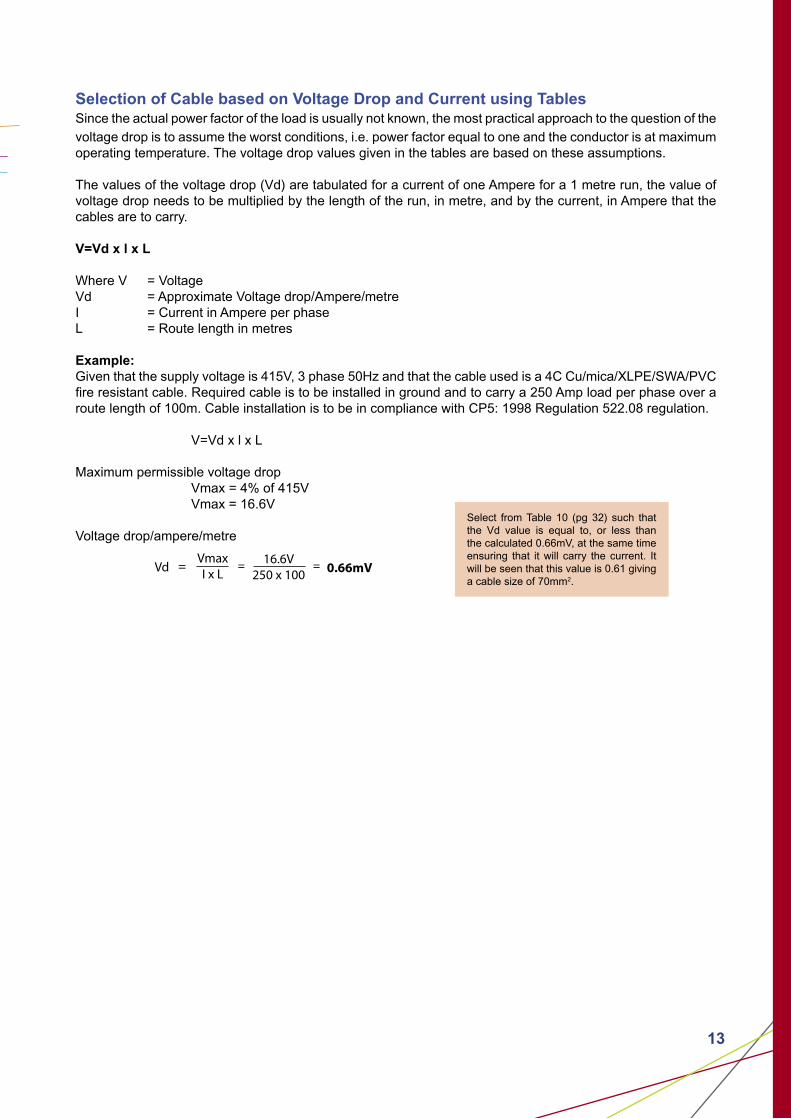
Selection of Cable based on Voltage Drop and Current using TablesSince the actual power factor of the load is usually not known, the most practical approach to the question of the voltage drop is to assume the worst conditions, i.e. power factor equal to one and the conductor is at maximum operating temperature. The voltage drop values given in the tables are based on these assumptions.
The values of the voltage drop (Vd) are tabulated for a current of one Ampere for a 1 metre run, the value of voltage drop needs to be multiplied by the length of the run, in metre, and by the current, in Ampere that the cables are to carry. V=Vd x l x L
Where V = VoltageVd = Approximate Voltage drop/Ampere/metreI = Current in Ampere per phaseL = Route length in metres
Example:Given that the supply voltage is 415V, 3 phase 50Hz and that the cable used is a 4C Cu/mica/XLPE/SWA/PVC fire resistant cable. Required cable is to be installed in ground and to carry a 250 Amp load per phase over a route length of 100m. Cable installation is to be in compliance with CP5: 1998 Regulation 522.08 regulation. V=Vd x l x L
Maximum permissible voltage drop Vmax = 4% of 415V Vmax = 16.6V
Voltage drop/ampere/metre
16.6V
250 x 100Vd = 0.66mV
VmaxI x L
= =
Select from Table 10 (pg 32) such that the Vd value is equal to, or less than the calculated 0.66mV, at the same time ensuring that it will carry the current. It will be seen that this value is 0.61 giving a cable size of 70mm2.
14 14
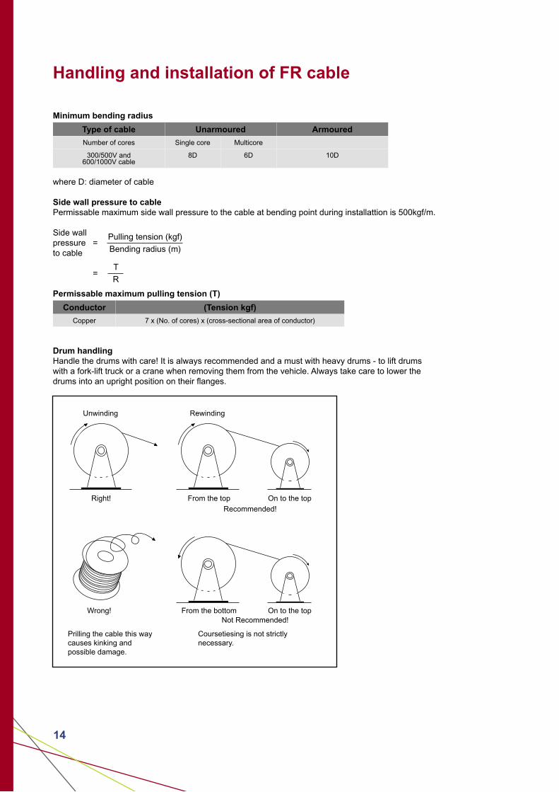
Handling and installation of FR cable
Minimum bending radius
Type of cable Unarmoured Armoured
Number of cores Single core Multicore
300/500V and600/1000V cable
8D 6D 10D
where D: diameter of cable
Side wall pressure to cablePermissable maximum side wall pressure to the cable at bending point during installattion is 500kgf/m.
Side wall pressure = to cable
=
Permissable maximum pulling tension (T)
Conductor (Tension kgf)
Copper 7 x (No. of cores) x (cross-sectional area of conductor)
Drum handlingHandle the drums with care! It is always recommended and a must with heavy drums - to lift drums with a fork-lift truck or a crane when removing them from the vehicle. Always take care to lower the drums into an upright position on their flanges.
Pulling tension (kgf)
Bending radius (m)
T
R
Unwinding Rewinding
Right! From the top On to the top
Recommended!
Wrong! From the bottom On to the topNot Recommended!
Prilling the cable this waycauses kinking andpossible damage.
Coursetiesing is not strictlynecessary.

15
LSFLOW SMOKE
HALOGEN FREE CABLES
16 16
DRAKA SCM LOW SMOKE HALOGEN FREE CABLES
In certain applications, cables under fire conditions have become a major concern. When conventional cables burn, they may emit smoke, halogen and toxic gases that may obscure vision and may be harmful to both equipment and human beings.
After years of research and development, SCM is manufacturing and supplying Low Smoke Halogen Free Cables which meets the severe requirements of cables under fire condition.
Unlike conventional cables, Low Smoke Halogen Free Cables have the following characteristics:-
1. Low Smoke: When the cable is on fire, it does not liberate large volume of dense black smoke. These cables when ignited will only produce a limited amount of smoke. This property helps to improve safety in areas where there are limited means to escape in the event of an emergency, or where large crowds are regularly in attendance.
2. Halogen Free: When the cable is on fire, it does not emit any halogen gases. These are acidic and will attack equipment and human beings. The property helps to protect computer, electronic/ communication equipment and reduces thee toxicity of thee gases emitted from the fire. This reduces the risk of personnel engaged in vital operations being incapacitated and the safe escape of people in an emergency.
With the superior fire performance, these range of cables are recommended for use in the following areas:
1. Underground tunnels, lifts, power stations2. Mass Rapid Transit System3. Airports4. Large buildings/Multi Story Buildings5. Critical areas of an installations e.g. escape route of an installation6. Oil Platforms/Ships7. Areas where masses of people gather and areas with limited means of escape in the event of a fire8. Military installations/equipment/machines9. Critical circuits that must continue to operate in case of a fire. e.g. Fire alarms, emergency lifts, pumps circuits etc.
17
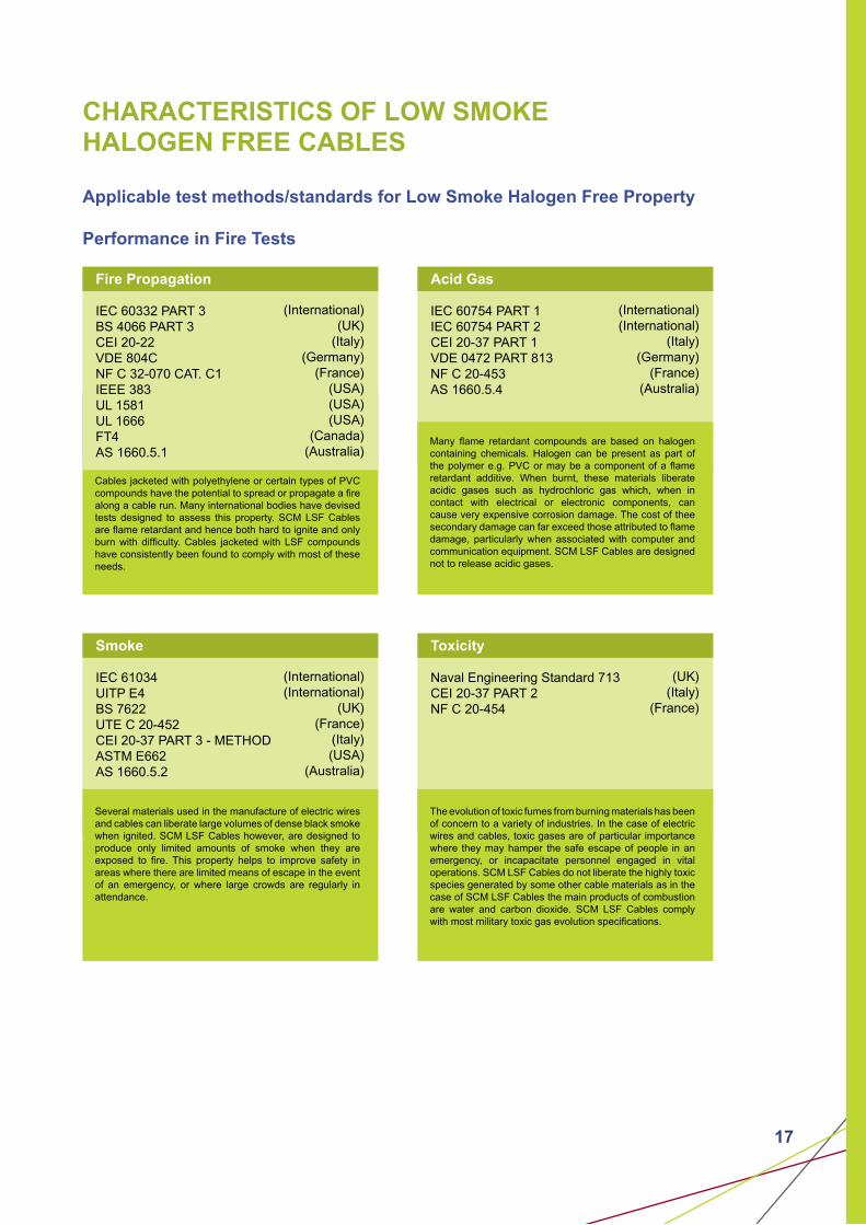
CHARACTERISTICS OF LOW SMOKE HALOGEN FREE CABLES
Applicable test methods/standards for Low Smoke Halogen Free Property
Performance in Fire Tests
(International)(UK)
(Italy)(Germany)
(France)(USA)(USA)(USA)
(Canada) (Australia)
Fire Propagation
IEC 60332 PART 3BS 4066 PART 3CEI 20-22VDE 804CNF C 32-070 CAT. C1IEEE 383UL 1581UL 1666FT4AS 1660.5.1
Cables jacketed with polyethylene or certain types of PVC compounds have the potential to spread or propagate a fire along a cable run. Many international bodies have devised tests designed to assess this property. SCM LSF Cables are flame retardant and hence both hard to ignite and only burn with difficulty. Cables jacketed with LSF compounds have consistently been found to comply with most of these needs.
(International)(International)
(Italy)(Germany)
(France)(Australia)
Acid Gas
IEC 60754 PART 1IEC 60754 PART 2CEI 20-37 PART 1VDE 0472 PART 813NF C 20-453AS 1660.5.4
Many flame retardant compounds are based on halogen containing chemicals. Halogen can be present as part of the polymer e.g. PVC or may be a component of a flame retardant additive. When burnt, these materials liberate acidic gases such as hydrochloric gas which, when in contact with electrical or electronic components, can cause very expensive corrosion damage. The cost of thee secondary damage can far exceed those attributed to flame damage, particularly when associated with computer and communication equipment. SCM LSF Cables are designed not to release acidic gases.
(International)(International)
(UK)(France)
(Italy)(USA)
(Australia)
Smoke
IEC 61034UITP E4BS 7622UTE C 20-452CEI 20-37 PART 3 - METHODASTM E662AS 1660.5.2
Several materials used in the manufacture of electric wires and cables can liberate large volumes of dense black smoke when ignited. SCM LSF Cables however, are designed to produce only limited amounts of smoke when they are exposed to fire. This property helps to improve safety in areas where there are limited means of escape in the event of an emergency, or where large crowds are regularly in attendance.
(UK)(Italy)
(France)
Toxicity
Naval Engineering Standard 713CEI 20-37 PART 2NF C 20-454
The evolution of toxic fumes from burning materials has been of concern to a variety of industries. In the case of electric wires and cables, toxic gases are of particular importance where they may hamper the safe escape of people in an emergency, or incapacitate personnel engaged in vital operations. SCM LSF Cables do not liberate the highly toxic species generated by some other cable materials as in the case of SCM LSF Cables the main products of combustion are water and carbon dioxide. SCM LSF Cables comply with most military toxic gas evolution specifications.

18 18
CONSTRUCTION OF CABLE
1
2
345678
Construction
1 - Conductor Stranded annealed copper
2 - Insulation XLPE or Low smoke halogen free (LSF) compound
3 - Shield* Aluminium foil with tinned copper drain wire
4 - Filler* LSF filler or polypropylene split yarn
5 - Binder Tape* Polyester tape
6 - Bedding* Low smoke halogen free (LSF) compound
7 - Armour*/# Galvanised steel wire (aluminium or copper wire for single core)
8 - Sheath Low smoke halogen free (LSF) compound
* Optional: Depending on requirement# Braided armour also available on request
1
2
8
1
24568
Identification of cores:
No. of cores Single Two Three Four Five & above Pairs
ColourNatural or
other colour on request
Red and BlackRed, Yellow
and BlueRed, Yellow,
Blue and Black
Black with white numbering (others on request)
Black with white numbering
Note: Special construction and design to customers’ specification can be provided upon request.
FOUR PAIR
FOUR CORE
SINGLE CORE

19
Applicable Standards
IEC 60502-1 Extruded solid dielectric insulated power cables for rated voltage of 1 kV up to 30 kV
IEC 60228/BS 6360 Conductors of insulated cables
IEC 60754-1/BS 6425-1 Test on gases evolved during combustion of electric cables -Determination of the amount of halogen acid gases
IEC 60754-2/BS 6425-2 Test on gases evolved during combustion of electric cables -Determination of degree of acidity of gases evolved by measuring PH and conductivity
IEC 61034/BS 7622 Measurement of smoke density of electric cables burning under defined conditions
BS 6724 Armoured cables for electricity supply having thermosetting insulation with low emission of smoke and corrosive gases when affected by fire
BS 7211 Thermosetting insulated cables (non-armoured) for electric power and lighting with low emission of smoke and corrosive gases when affected by fire
BS 7846 600/1000V armoured fire-resistant electric cables having low emission of smoke and corrosive gases when affected by fire
20 20
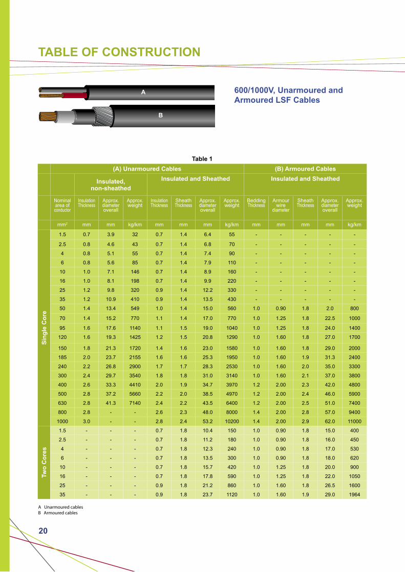
TABLE OF CONSTRUCTION
600/1000V, Unarmoured and Armoured LSF Cables
Table 1
(A) Unarmoured Cables (B) Armoured Cables
Insulated, non-sheathed
Insulated and Sheathed Insulated and Sheathed
Nominalarea of
conductor
Insulation Thickness
Approx.diameteroverall
Approx.weight
Insulation Thickness
SheathThickness
Approx.diameteroverall
Approx.weight
BeddingThickness
Armourwire
diameter
Sheath Thickness
Approx.diameteroverall
Approx.weight
mm2 mm mm kg/km mm mm mm kg/km mm mm mm mm kg/km
Sin
gle
Co
re
1.5 0.7 3.9 32 0.7 1.4 6.4 55 - - - - -
2.5 0.8 4.6 43 0.7 1.4 6.8 70 - - - - -
4 0.8 5.1 55 0.7 1.4 7.4 90 - - - - -
6 0.8 5.6 85 0.7 1.4 7.9 110 - - - - -
10 1.0 7.1 146 0.7 1.4 8.9 160 - - - - -
16 1.0 8.1 198 0.7 1.4 9.9 220 - - - - -
25 1.2 9.8 320 0.9 1.4 12.2 330 - - - - -
35 1.2 10.9 410 0.9 1.4 13.5 430 - - - - -
50 1.4 13.4 549 1.0 1.4 15.0 560 1.0 0.90 1.8 2.0 800
70 1.4 15.2 770 1.1 1.4 17.0 770 1.0 1.25 1.8 22.5 1000
95 1.6 17.6 1140 1.1 1.5 19.0 1040 1.0 1.25 1.8 24.0 1400
120 1.6 19.3 1425 1.2 1.5 20.8 1290 1.0 1.60 1.8 27.0 1700
150 1.8 21.3 1720 1.4 1.6 23.0 1580 1.0 1.60 1.8 29.0 2000
185 2.0 23.7 2155 1.6 1.6 25.3 1950 1.0 1.60 1.9 31.3 2400
240 2.2 26.8 2900 1.7 1.7 28.3 2530 1.0 1.60 2.0 35.0 3300
300 2.4 29.7 3540 1.8 1.8 31.0 3140 1.0 1.60 2.1 37.0 3800
400 2.6 33.3 4410 2.0 1.9 34.7 3970 1.2 2.00 2.3 42.0 4800
500 2.8 37.2 5660 2.2 2.0 38.5 4970 1.2 2.00 2.4 46.0 5900
630 2.8 41.3 7140 2.4 2.2 43.5 6400 1.2 2.00 2.5 51.0 7400
800 2.8 - - 2.6 2.3 48.0 8000 1.4 2.00 2.8 57.0 9400
1000 3.0 - - 2.8 2.4 53.2 10200 1.4 2.00 2.9 62.0 11000
Two
Co
res
1.5 - - - 0.7 1.8 10.4 150 1.0 0.90 1.8 15.0 400
2.5 - - - 0.7 1.8 11.2 180 1.0 0.90 1.8 16.0 450
4 - - - 0.7 1.8 12.3 240 1.0 0.90 1.8 17.0 530
6 - - - 0.7 1.8 13.5 300 1.0 0.90 1.8 18.0 620
10 - - - 0.7 1.8 15.7 420 1.0 1.25 1.8 20.0 900
16 - - - 0.7 1.8 17.8 590 1.0 1.25 1.8 22.0 1050
25 - - - 0.9 1.8 21.2 860 1.0 1.60 1.8 26.5 1600
35 - - - 0.9 1.8 23.7 1120 1.0 1.60 1.9 29.0 1964
A Unarmoured cablesB Armoured cables
A
B
21
600/1000V, Unarmoured and Armoured LSF Cables
Table 2
(C) Unarmoured Cables (D) Armoured Cables
Nominalarea of
conductor
Insulation Thickness
SheathThickness
Approx.diameteroverall
Approx.weight
BeddingThickness
Armourwire
diameter
Sheath Thickness
Approx.diameteroverall
Approx.weight
mm2 mm mm mm kg/km mm mm mm mm kg/km
Th
ree
Co
res
1.5 0.7 1.8 11.4 170 1.0 0.90 1.8 15.9 450
2.5 0.7 1.8 12.3 215 1.0 0.90 1.8 16.8 510
4 0.7 1.8 13.44 280 1.0 0.90 1.8 18.0 610
6 0.7 1.8 14.7 360 1.0 1.25 1.8 20.0 820
10 0.7 1.8 16.7 510 1.0 1.25 1.8 21.6 1000
16 0.7 1.8 18.5 740 1.0 1.25 1.8 23.8 1300
25 0.9 1.8 22.0 1100 1.0 1.60 1.8 28.0 1900
35 0.9 1.8 25.0 140 1.0 1.60 1.8 31.0 2400
50 1.0 1.8 28.0 1900 1.0 1.60 1.9 34.5 3000
70 1.1 1.9 32.0 2600 1.2 2.00 2.1 40.5 4300
95 1.1 2.0 37.0 3500 1.2 2.00 2.0 45.0 5400
120 1.2 2.1 42.0 4400 1.2 2.00 2.3 49.0 6600
150 1.4 2.4 47.0 5500 1.4 2.50 2.5 55.0 8300
185 1.6 2.4 52.0 6800 1.4 2.50 2.7 60.0 10000
240 1.7 2.6 58.0 8800 1.4 2.50 2.9 67.0 12000
300 1.8 2.7 64.0 10000 1.6 2.50 3.0 74.0 15000
Fo
ur
Co
res
1.5 0.7 1.8 11.4 170 0.90 0.90 1.8 15.9 450
2.5 0.7 1.8 12.3 215 0.90 0.90 1.8 16.8 510
4 0.7 1.8 13.44 280 0.90 1.25 1.8 18.0 610
6 0.7 1.8 14.7 360 1.25 1.25 1.8 20.0 820
10 0.7 1.8 16.7 510 1.25 1.25 1.8 21.6 1000
16 0.7 1.8 18.5 740 1.25 1.60 1.8 23.8 1300
25 0.9 1.8 22.0 1100 1.60 1.60 1.8 28.0 1900
35 0.9 1.8 25.0 1400 1.60 1.60 1.8 31.0 2400
50 1.0 1.8 28.0 1900 1.60 2.00 1.9 34.5 3000
70 1.1 2.0 32.0 2600 2.00 2.00 2.1 40.5 4300
95 1.1 2.1 37.0 3500 2.00 2.00 2.0 45.0 5400
120 1.2 2.3 42.0 4400 2.00 2.50 2.3 49.0 6600
150 1.4 2.4 47.0 5500 2.50 2.50 2.5 55.0 8300
185 1.6 2.6 52.0 6800 2.50 2.50 2.7 60.0 10000
240 1.7 2.8 58.0 8800 2.50 3.15 2.9 67.0 12000
300 1.8 3.0 64.0 10000 2.50 3.15 3.0 74.0 15000
C Unarmoured cablesD Armoured cables* Multicore unarmoured and armoured fire resistant cables are available upon request
C
D

22 22
300/500V, Unarmoured and Armoured LSF Cables
Table 3
(E) Unarmoured Cables (F) Armoured Cables
Nominalarea of
conductor
No. & Diameterof wires
Insulation Thickness
SheathThickness
Approx.diameteroverall
Approx.weight
BeddingThickness
Armourwire
diameter
Sheath Thickness
Approx.diameteroverall
Approx.weight
mm2 No./mm mm mm mm kg/km mm mm mm mm kg/km
Sin
gle
Co
re
0.75 7/0.37 0.55 0.5 4.1 22 0.5 0.9 1.4 8.9 155
1 7/0.44 0.55 0.5 4.3 26 0.5 0.9 1.4 9.1 165
1.5 7/0.53 0.55 0.5 4.6 32 0.5 0.9 1.4 9.4 180
2.5 7/0.67 0.55 0.5 5.0 43 0.5 0.9 1.4 9.8 200
4 7/0.85 0.55 0.5 5.6 60 0.5 0.9 1.4 10.4 240
Two
Co
res
0.75 7/0.37 0.55 0.5 7.0 64 0.5 0.9 1.4 11.8 285
1 7/0.44 0.55 0.5 7.4 74 0.5 0.9 1.4 12.2 310
1.5 7/0.53 0.55 0.5 8.0 92 0.5 0.9 1.4 12.8 345
2.5 7/0.67 0.55 0.5 8.8 120 0.5 0.9 1.4 13.6 400
4 7/0.85 0.55 0.5 9.9 165 0.5 0.9 1.4 14.7 475
Th
ree
Co
res 0.75 7/0.37 0.55 0.5 7.5 75 0.5 0.9 1.4 12.3 310
1 7/0.44 0.55 0.5 7.9 88 0.5 0.9 1.4 12.7 355
1.5 7/0.53 0.55 0.5 8.5 110 0.5 0.9 1.4 13.3 375
2.5 7/0.67 0.55 0.5 9.4 150 0.5 0.9 1.4 14.2 445
4 7/0.85 0.55 0.5 10.6 205 0.5 0.9 1.4 15.4 535
Fo
ur
Co
res
0.75 7/0.37 0.55 0.5 8.3 90 0.5 0.9 1.4 13.1 360
1 7/0.44 0.55 0.5 8.7 105 0.5 0.9 1.4 13.5 380
1.5 7/0.53 0.55 0.5 9.4 135 0.5 0.9 1.4 14.2 430
2.5 7/0.67 0.55 0.5 10.4 180 0.5 0.9 1.4 15.2 500
4 7/0.85 0.55 0.5 11.7 255 0.5 0.9 1.4 16.7 620
E Unarmoured fire resistant cableF Armoured fire resistant cable* Multicore unarmoured and armoured fire resistant cables are available upon request
E
F

23
300/500V, Unarmoured and Armoured Shielded LSF Cables
Table 4
(E) Unarmoured Cables (F) Armoured Cables
Nominalarea of
conductor
No. & Diameterof wires
Insulation Thickness
SheathThickness
Approx.diameteroverall
Approx.weight
BeddingThickness
Armourwire
diameter
Sheath Thickness
Approx.diameteroverall
Approx.weight
mm2 No./mm mm mm mm kg/km mm mm mm mm kg/km
On
e p
air 0.75 7/0.37 0.5 0.8 7.9 65 0.8 0.9 1.4 12.7 300
1 7/0.43 0.6 0.8 8.5 75 0.8 0.9 1.4 13.3 340
1.5 7/0.53 0.5 0.8 9.1 90 0.8 0.9 1.4 13.9 370
2.5 7/0.67 0.6 0.8 9.9 110 0.8 0.9 1.4 14.7 420
Two
pai
r 0.75 7/0.37 0.5 0.8 10.0 100 0.8 0.9 1.4 14.8 410
1 7/0.43 0.6 0.9 11.0 125 0.9 0.9 1.4 15.8 460
1.5 7/0.53 0.6 0.9 11.8 150 0.9 0.9 1.5 16.8 520
2.5 7/0.67 0.6 1.0 13.1 205 1.0 0.9 1.5 18.1 605
Th
ree
pai
r 0.75 7/0.37 0.5 1.0 12.2 145 1.0 0.9 1.5 17.2 565
1 7/0.43 0.6 1.0 13.1 170 1.0 0.9 1.5 18.1 600
1.5 7/0.53 0.6 1.0 14.1 215 1.0 0.9 1.6 19.3 655
2.5 7/0.67 0.6 1.1 15.7 290 1.1 1.25 1.6 21.6 920
Fo
ur
pai
r 0.75 7/0.37 0.5 1.0 13.7 180 1.0 0.9 1.5 18.7 600
1 7/0.43 0.6 1.0 14.7 215 1.0 1.25 1.6 20.6 820
1.5 7/0.53 0.6 1.1 16.1 280 1.1 1.25 1.6 22.0 920
2.5 7/0.67 0.6 1.1 17.7 370 1.1 1.25 1.6 23.8 1090
G Unarmoured fire resistant cableH Armoured fire resistant cable* Multi-pairs unarmoured and armoured shielded fire resistant cables are available upon request
G
H

24 24

25
TABLES FOR MAX-FOH & LSF CABLES
26 26
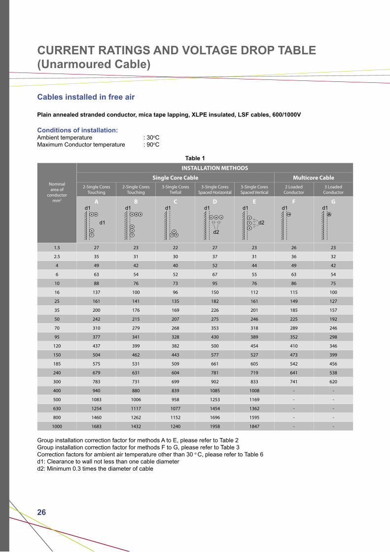
CURRENT RATINGS AND VOLTAGE DROP TABLE(Unarmoured Cable)
Cables installed in free air
Plain annealed stranded conductor, mica tape lapping, XLPE insulated, LSF cables, 600/1000V
Conditions of installation:Ambient temperature : 30oCMaximum Conductor temperature : 90oC
Table 1
Nominal area of
conductor mm2
INSTALLATION METHODS
Single Core Cable Multicore Cable
2-Single Cores Touching
2-Single Cores Touching
3-Single Cores Trefoil
3-Single Cores Spaced Horizontal
3-Single Cores Spaced Vertical
2 LoadedConductor
3 LoadedConductor
A B C D E F G
1.5 27 23 22 27 23 26 23
2.5 35 31 30 37 31 36 32
4 49 42 40 52 44 49 42
6 63 54 52 67 55 63 54
10 88 76 73 95 76 86 75
16 137 100 96 150 112 115 100
25 161 141 135 182 161 149 127
35 200 176 169 226 201 185 157
50 242 215 207 275 246 225 192
70 310 279 268 353 318 289 246
95 377 341 328 430 389 352 298
120 437 399 382 500 454 410 346
150 504 462 443 577 527 473 399
185 575 531 509 661 605 542 456
240 679 631 604 781 719 641 538
300 783 731 699 902 833 741 620
400 940 880 839 1085 1008 - -
500 1083 1006 958 1253 1169 - -
630 1254 1117 1077 1454 1362 - -
800 1460 1262 1152 1696 1595 - -
1000 1683 1432 1240 1958 1847 - -
Group installation correction factor for methods A to E, please refer to Table 2Group installation correction factor for methods F to G, please refer to Table 3Correction factors for ambient air temperature other than 30 o C, please refer to Table 6d1: Clearance to wall not less than one cable diameterd2: Minimum 0.3 times the diameter of cable
d1
d1
d1 d1 d1
d2
d1
d2
d1 d1
27
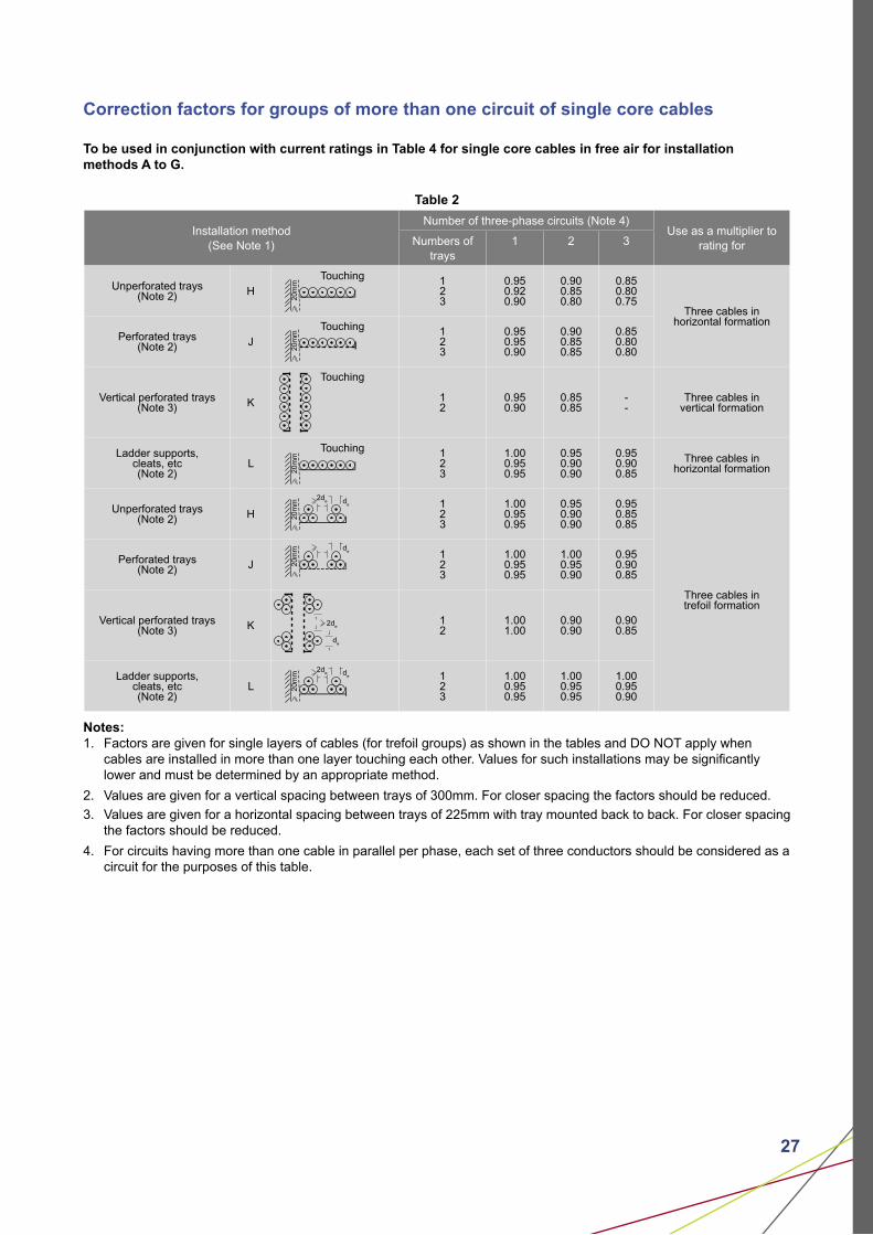
Correction factors for groups of more than one circuit of single core cables
To be used in conjunction with current ratings in Table 4 for single core cables in free air for installation methods A to G.
Table 2
Installation method(See Note 1)
Number of three-phase circuits (Note 4)Use as a multiplier to
rating forNumbers of trays
1 2 3
Unperforated trays(Note 2) H
Touching 123
0.950.920.90
0.900.850.80
0.850.800.75
Three cables in horizontal formation
Perforated trays(Note 2) J
Touching 123
0.950.950.90
0.900.850.85
0.850.800.80
Vertical perforated trays(Note 3) K
Touching
12
0.950.90
0.850.85
--
Three cables in vertical formation
Ladder supports, cleats, etc (Note 2)
L Touching 1
23
1.000.950.95
0.950.900.90
0.950.900.85
Three cables in horizontal formation
Unperforated trays(Note 2) H
123
1.000.950.95
0.950.900.90
0.950.850.85
Three cables in trefoil formation
Perforated trays(Note 2) J
123
1.000.950.95
1.000.950.90
0.950.900.85
Vertical perforated trays(Note 3) K 1
21.001.00
0.900.90
0.900.85
Ladder supports, cleats, etc (Note 2)
L123
1.000.950.95
1.000.950.95
1.000.950.90
Notes:1. Factors are given for single layers of cables (for trefoil groups) as shown in the tables and DO NOT apply when cables are installed in more than one layer touching each other. Values for such installations may be significantly lower and must be determined by an appropriate method.
2. Values are given for a vertical spacing between trays of 300mm. For closer spacing the factors should be reduced.
3. Values are given for a horizontal spacing between trays of 225mm with tray mounted back to back. For closer spacing the factors should be reduced.
4. For circuits having more than one cable in parallel per phase, each set of three conductors should be considered as a circuit for the purposes of this table.
20m
m20
mm
20m
m20
mm d
e
20m
m
2de
de
20m
m de
de
2de
2de

28 28
Correction factors for groups of more than one multicore cable
To be used in conjunction with current ratings in Table 1 for multicore cables in free air for installation methods F to G.
Table 3
Installation method Number of traysNumber of cables
1 2 3 4 6 9
Unperforated trays(Note 2) M
Touching123
0.950.950.95
0.850.850.85
0.800.750.75
0.750.750.70
0.700.700.65
0.700.650.60
Spaced123
1.000.950.95
0.950.950.95
0.950.900.90
0.950.900.90
0.900.850.85
---
Perforated trays(Note 2) N
Touching123
1.001.001.00
0.900.850.85
0.800.800.80
0.800.750.75
0.750.750.70
0.750.700.65
Spaced123
1.001.001.00
1.001.001.00
1000.950.95
0.950.900.90
0.900.850.85
---
Vertical perforated trays(Note 3) O
Touching12
1.001.00
0.900.90
0.800.80
0.750.75
0.750.70
0.700.70
Spaced12
1.001.00
0.900.90
0.900.90
0.900.85
0.850.85
--
Ladder supportscleats, etc.
(Note 2)P
Touching 123
1.001.001.00
0.850.850.85
0.800.800.80
0.800.800.75
0.800.750.75
0.800.750.70
Spaced123
1.001.001.00
1.001.001.00
1.001.000.95
1.000.950.95
1.000.950.95
---
Notes:1. Factors apply to single layer groups of cables as shown above and do NOT apply when cables are installed in more than one layer touching each other. Values for such installations may be significantly lower and must be determined by an appropriate method.
2. Values are given for a vertical spacing between trays of 300mm . For closer vertical spacing the factors should be reduced.
3. Values are given for a horizontal spacing between trays of 225mm with trays mounted back to back. For closer spacing the factors should be reduced.
20m
m20
mm
de
20m
m20
mm
A
de
20m
m
de
20m
m
de

29
Cables in conduit and trunking, and bunched cables on a surface
Plain annealed stranded conductor, mica tape lapping, XLPE insulated, LSF cables, 600/1000V
Conditions of Installation:Ambient temperature : 30oCMaximum conductor temperature : 90oC
Table 4
Nominal area of
conductor
mm2
Insulated conductors inR
Insulated conductors inS
Multicore cable on a wallT
2 loadedConductor
3 loadedConductor
2 loadedConductor
3 loadedConductor
2 loadedConductor
3 loadedConductor
Amp Amp Amp
1.5 19 17 23 20 24 22
2.5 26 23 31 27 33 30
4 35 31 42 37 45 40
6 45 40 54 48 58 52
10 61 54 74 66 80 71
16 81 73 100 89 107 96
25 106 95 133 117 138 119
35 131 117 164 144 171 147
50 158 141 198 175 210 179
70 200 179 254 222 269 229
95 241 216 306 269 328 278
120 278 249 354 312 382 322
150 318 285 - - 441 371
185 362 324 - - 506 424
240 424 380 - - 599 500
300 486 435 - - 693 576
400 579 519 - - 860 692
500 664 595 - - 994 797
630 765 685 - - 1155 923
800 885 792 - - 1349 1074
1000 1014 908 - - 1560 1237
For group correction factors, please refer to Table 5Correction factors for ambient temperatures other than 30oC, refer to Table 6
30 30
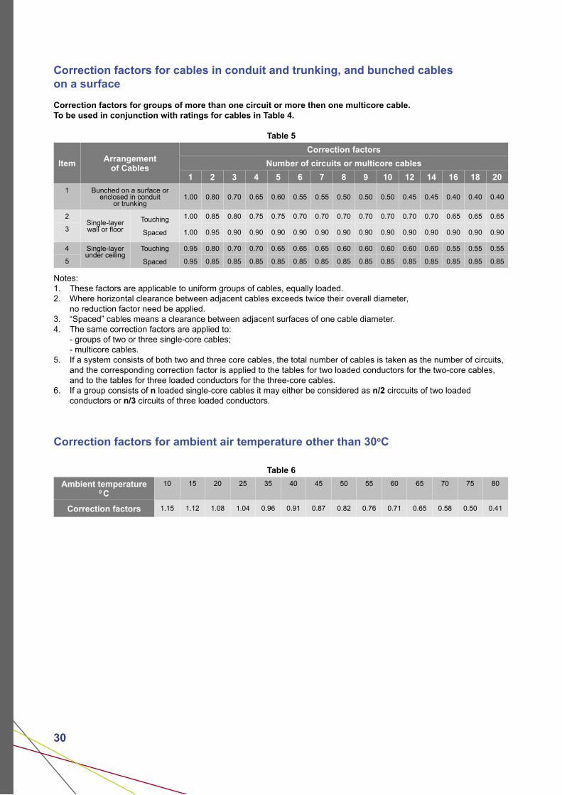
Correction factors for cables in conduit and trunking, and bunched cables on a surface
Correction factors for groups of more than one circuit or more then one multicore cable.To be used in conjunction with ratings for cables in Table 4.
Table 5
Item Arrangementof Cables
Correction factors
Number of circuits or multicore cables
1 2 3 4 5 6 7 8 9 10 12 14 16 18 20
1 Bunched on a surface orenclosed in conduit
or trunking1.00 0.80 0.70 0.65 0.60 0.55 0.55 0.50 0.50 0.50 0.45 0.45 0.40 0.40 0.40
2Single-layerwall or floor
Touching
Spaced
1.00 0.85 0.80 0.75 0.75 0.70 0.70 0.70 0.70 0.70 0.70 0.70 0.65 0.65 0.65
3 1.00 0.95 0.90 0.90 0.90 0.90 0.90 0.90 0.90 0.90 0.90 0.90 0.90 0.90 0.90
4 Single-layerunder ceiling
Touching
Spaced
0.95 0.80 0.70 0.70 0.65 0.65 0.65 0.60 0.60 0.60 0.60 0.60 0.55 0.55 0.55
5 0.95 0.85 0.85 0.85 0.85 0.85 0.85 0.85 0.85 0.85 0.85 0.85 0.85 0.85 0.85
Notes:1. These factors are applicable to uniform groups of cables, equally loaded.2. Where horizontal clearance between adjacent cables exceeds twice their overall diameter, no reduction factor need be applied.3. “Spaced” cables means a clearance between adjacent surfaces of one cable diameter.4. The same correction factors are applied to: - groups of two or three single-core cables; - multicore cables.5. If a system consists of both two and three core cables, the total number of cables is taken as the number of circuits, and the corresponding correction factor is applied to the tables for two loaded conductors for the two-core cables, and to the tables for three loaded conductors for the three-core cables.6. If a group consists of n loaded single-core cables it may either be considered as n/2 circcuits of two loaded conductors or n/3 circuits of three loaded conductors.
Correction factors for ambient air temperature other than 30oC
Table 6
Ambient temperature 0 C
10 15 20 25 35 40 45 50 55 60 65 70 75 80
Correction factors 1.15 1.12 1.08 1.04 0.96 0.91 0.87 0.82 0.76 0.71 0.65 0.58 0.50 0.41

31
Voltage drop table (Unarmoured Cables)
Voltage drop for single core cables per amp per metre
Table 7
Nominalarea of
conductor
(mm2)
For For
(mV)
For
(mV)
For
(mV)AC
(mV)DC
(mV)
1.5 30.86 30.86 26.73 26.73 26.73
2.5 18.90 18.90 16.37 16.37 16.37
4 11.76 11.76 10.19 10.19 10.19
6 7.86 7.86 6.81 6.81 6.81
10 4.67 4.66 4.04 4.04 4.05
16 2.95 2.94 2.55 2.55 2.56
25 1.87 1.85 1.62 1.62 1.63
35 1.35 1.34 1.17 1.17 1.19
50 1.01 0.99 0.87 0.88 0.90
70 0.71 0.68 0.61 0.62 0.65
95 0.52 0.49 0.45 0.45 0.50
120 0.43 0.39 0.37 0.38 0.42
150 0.36 0.32 0.32 0.33 0.37
185 0.30 0.25 0.26 0.28 0.33
240 0.25 0.19 0.22 0.24 0.29
300 0.22 0.15 0.20 0.21 0.28
400 0.20 0.12 0.17 0.20 0.26
500 0.19 0.093 0.16 0.18 0.25
630 0.18 0.072 0.15 0.17 0.25
800 0.17 0.056 0.15 0.17 0.24
1000 0.16 0.045 0.14 0.16 0.24
Voltage drop for multi-core cables per amp per metre
Table 8
Nominalarea of
conductor(mm2)
For twin-coreFor 3 and 4 cores
(mV)AC(mV)
DC(mV)
16 2.90 2.90 2.60
25 1.90 1.90 1.60
35 1.30 1.30 1.20
50 1.00 0.99 0.87
70 0.70 0.68 0.61
95 0.52 0.49 0.45
120 0.42 0.39 0.36
150 0.35 0.32 0.30
185 0.29 0.25 0.25
240 0.24 0.19 0.21
300 0.21 0.15 0.19
D D
32 32
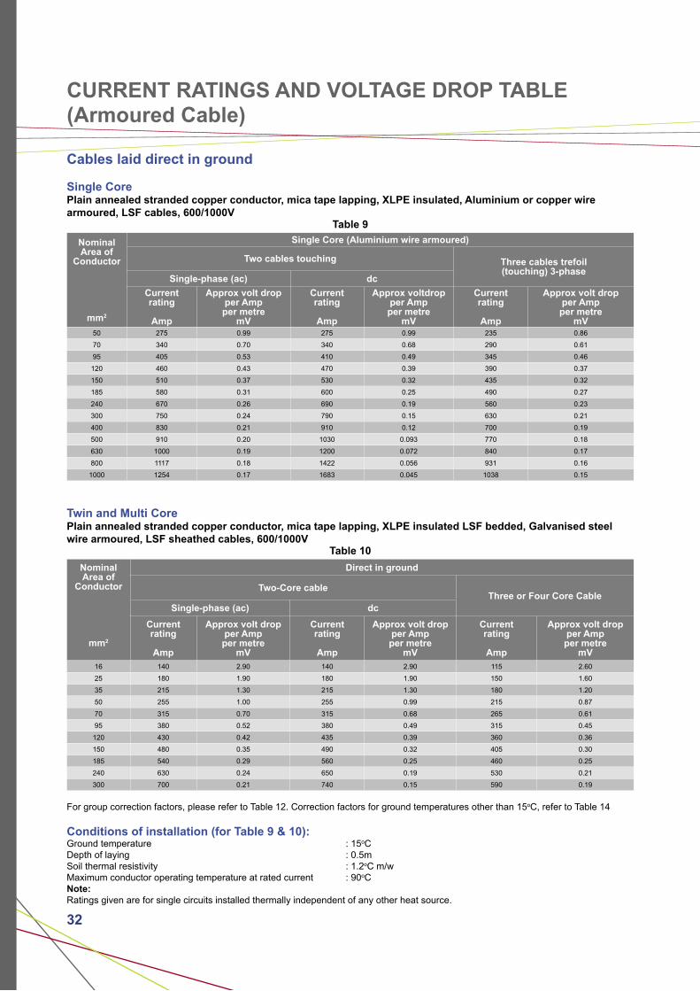
CURRENT RATINGS AND VOLTAGE DROP TABLE (Armoured Cable)
Cables laid direct in ground
Single CorePlain annealed stranded copper conductor, mica tape lapping, XLPE insulated, Aluminium or copper wire armoured, LSF cables, 600/1000V
Table 9
Nominal Area of
Conductor
mm2
Single Core (Aluminium wire armoured)
Two cables touching Three cables trefoil(touching) 3-phase
Single-phase (ac) dc
Currentrating
Amp
Approx volt dropper Ampper metre
mV
Currentrating
Amp
Approx voltdropper Ampper metre
mV
Currentrating
Amp
Approx volt dropper Ampper metre
mV50 275 0.99 275 0.99 235 0.86
70 340 0.70 340 0.68 290 0.61
95 405 0.53 410 0.49 345 0.46
120 460 0.43 470 0.39 390 0.37
150 510 0.37 530 0.32 435 0.32
185 580 0.31 600 0.25 490 0.27
240 670 0.26 690 0.19 560 0.23
300 750 0.24 790 0.15 630 0.21
400 830 0.21 910 0.12 700 0.19
500 910 0.20 1030 0.093 770 0.18
630 1000 0.19 1200 0.072 840 0.17
800 1117 0.18 1422 0.056 931 0.16
1000 1254 0.17 1683 0.045 1038 0.15
Twin and Multi CorePlain annealed stranded copper conductor, mica tape lapping, XLPE insulated LSF bedded, Galvanised steel wire armoured, LSF sheathed cables, 600/1000V
Table 10
Nominal Area of
Conductor
mm2
Direct in ground
Two-Core cableThree or Four Core Cable
Single-phase (ac) dc
Currentrating
Amp
Approx volt dropper Ampper metre
mV
Currentrating
Amp
Approx volt dropper Ampper metre
mV
Currentrating
Amp
Approx volt dropper Ampper metre
mV16 140 2.90 140 2.90 115 2.60
25 180 1.90 180 1.90 150 1.60
35 215 1.30 215 1.30 180 1.20
50 255 1.00 255 0.99 215 0.87
70 315 0.70 315 0.68 265 0.61
95 380 0.52 380 0.49 315 0.45
120 430 0.42 435 0.39 360 0.36
150 480 0.35 490 0.32 405 0.30
185 540 0.29 560 0.25 460 0.25
240 630 0.24 650 0.19 530 0.21
300 700 0.21 740 0.15 590 0.19
For group correction factors, please refer to Table 12. Correction factors for ground temperatures other than 15oC, refer to Table 14
Conditions of installation (for Table 9 & 10): Ground temperature : 15oCDepth of laying : 0.5mSoil thermal resistivity : 1.2oC m/wMaximum conductor operating temperature at rated current : 90oCNote:Ratings given are for single circuits installed thermally independent of any other heat source.

33
Cables run in single way ducts
Plain annealed stranded copper conductor, mica tape lapping, XLPE insulated, armoured, LSF cables, 600/1000V
Table 11
Nominal area of
conductor
mm2
Single Core Two-Core Three or Four Core
Two cablesducts touching
Three cables ducts touching,trefoil
Currentrating
Amp
Approx volt drop
per Ampper metre
mV
Currentrating
Amp
Approx volt drop
per Ampper metre
mV
Currentrating
Amp
Approx volt drop
per Ampper metre
mV
Currentrating
Amp
Approx volt drop
per Ampper metre
mV
16 - - - - 115 2.90 94 2.6
25 - - - - 145 1.90 125 1.6
35 - - - - 175 1.30 150 1.2
50 255 1.10 235 0.93 210 1.00 175 0.87
70 310 0.80 280 0.70 260 0.70 215 0.61
95 365 0.65 330 0.56 310 0.52 260 0.45
120 410 0.55 370 0.48 355 0.42 300 0.36
150 445 0.50 405 0.43 400 0.35 335 0.30
185 485 0.45 440 0.39 455 0.29 380 0.25
240 550 0.40 500 0.35 520 0.24 440 0.21
300 610 0.37 550 0.32 590 0.21 495 0.19
400 640 0.35 580 0.30 - - - -
500 690 0.33 620 0.28 - - - -
630 750 0.30 670 0.26 - - - -
800 828 0.28 735 0.24 - - - -
1000 919 0.26 811 0.22 - - - -
For group correction factors, please refer to Table 13Correction factors for ground temperatures other than 15oC, refer to Table 14
Conditions of installation:Ground temperature : 15oCDepth of laying : 0.5mSoil thermal resistivity : 1.2oC m/wMaximum conductor operating temperature at rated current : 90oCAmbient air temperature : 25oC
Note:* Single core cables are aluminium wire armoured for a.c. systems.Ratings given are for single circuits installed thermally independent of any other heat source.
34 34
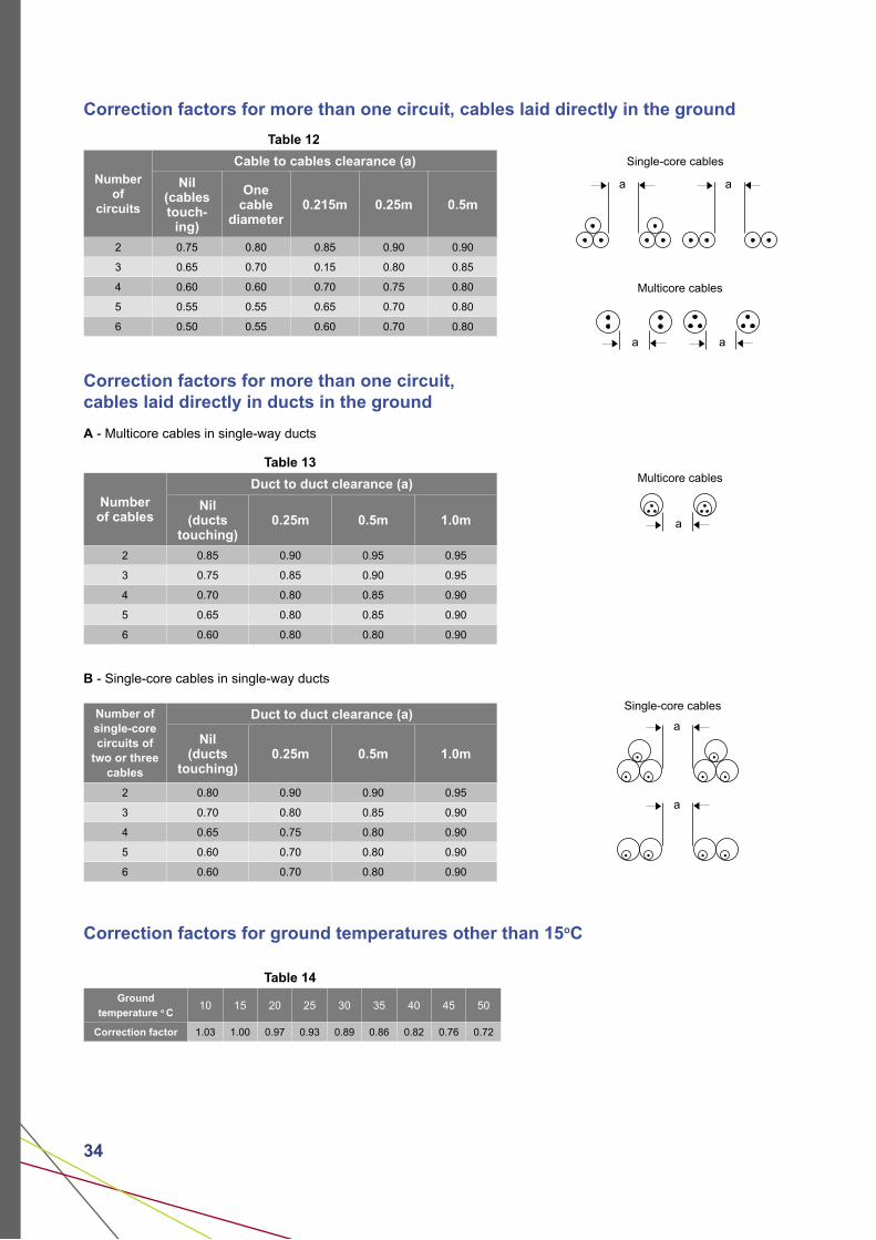
Correction factors for more than one circuit, cables laid directly in the ground
Table 12
Number of
circuits
Cable to cables clearance (a)
Nil(cables touch-
ing)
One cable
diameter0.215m 0.25m 0.5m
2 0.75 0.80 0.85 0.90 0.90
3 0.65 0.70 0.15 0.80 0.85
4 0.60 0.60 0.70 0.75 0.80
5 0.55 0.55 0.65 0.70 0.80
6 0.50 0.55 0.60 0.70 0.80
Correction factors for more than one circuit, cables laid directly in ducts in the ground
A - Multicore cables in single-way ducts
Table 13
Number of cables
Duct to duct clearance (a)
Nil(ducts
touching)0.25m 0.5m 1.0m
2 0.85 0.90 0.95 0.95
3 0.75 0.85 0.90 0.95
4 0.70 0.80 0.85 0.90
5 0.65 0.80 0.85 0.90
6 0.60 0.80 0.80 0.90
B - Single-core cables in single-way ducts
Number of single-core circuits of
two or three cables
Duct to duct clearance (a)
Nil(ducts
touching)0.25m 0.5m 1.0m
2 0.80 0.90 0.90 0.95
3 0.70 0.80 0.85 0.90
4 0.65 0.75 0.80 0.90
5 0.60 0.70 0.80 0.90
6 0.60 0.70 0.80 0.90
Correction factors for ground temperatures other than 15oC
Table 14
Ground
temperature o C10 15 20 25 30 35 40 45 50
Correction factor 1.03 1.00 0.97 0.93 0.89 0.86 0.82 0.76 0.72
Multicore cables
a a
Multicore cables
a
a
Single-core cables
Single-core cables
a
a
a
35
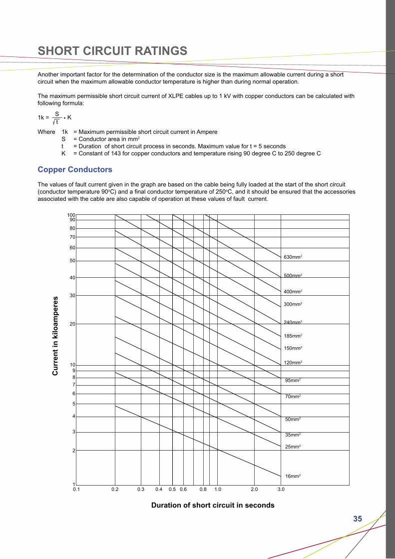
SHORT CIRCUIT RATINGS
Another important factor for the determination of the conductor size is the maximum allowable current during a short circuit when the maximum allowable conductor temperature is higher than during normal operation.
The maximum permissible short circuit current of XLPE cables up to 1 kV with copper conductors can be calculated with following formula:
1k =
Where 1k = Maximum permissible short circuit current in Ampere S = Conductor area in mm2
t = Duration of short circuit process in seconds. Maximum value for t = 5 seconds K = Constant of 143 for copper conductors and temperature rising 90 degree C to 250 degree C
Copper Conductors
The values of fault current given in the graph are based on the cable being fully loaded at the start of the short circuit (conductor temperature 90oC) and a final conductor temperature of 250oC, and it should be ensured that the accessories associated with the cable are also capable of operation at these values of fault current.
St
K
Cu
rren
t in
kilo
amp
eres
Duration of short circuit in seconds
10090
80
70
60
50
40
30
20
1098
7
6
5
4
3
2
10.1 0.2 0.3 0.4 0.5 0.6 0.8 1.0 2.0 3.0
630mm2
500mm2
400mm2
300mm2
240mm2
185mm2
150mm2
120mm2
95mm2
70mm2
50mm2
35mm2
25mm2
16mm2
36 36
TECHNICAL INFORMATION
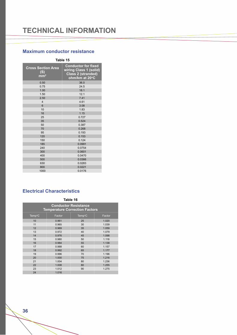
Maximum conductor resistance
Table 15
Cross Section Area (S)
mm2
Conductor for fixed wiring Class 1 (solid)
Class 2 (stranded)ohm/km at 20oC
0.50 36.00.75 24.51.00 18.11.50 12.12.50 7.41
4 4.616 3.08
10 1.8316 1.1525 0.72735 0.52450 0.38770 0.26895 0.193
120 0.153150 0.124185 0.0991240 0.0754300 0.0601400 0.0470500 0.0366630 0.0283800 0.0221
1000 0.0176
Electrical Characteristics
Table 16
Conductor ResistanceTemperature Correction Factors
TempoC Factor TempoC Factor
10 0.961 25 1.020
11 0.965 30 1.039
12 0.969 35 1.059
13 0.972 40 1.079
14 0.976 45 1.098
15 0.980 50 1.118
16 0.984 55 1.138
17 0.988 60 1.157
18 0.992 65 1.177
19 0.996 70 1.196
20 1.000 75 1.216
21 1.004 80 1.236
22 1.008 80 1.255
23 1.012 90 1.275
24 1.016
37
Building & Construction Projects Government / Infrastructure
Central Ministries BuildingChangi Airport Terminals 1, 2 & 3Changi Water Reclamation Plant (CWRP)Expressways (CTE/KPE & Tuas Tunnel)ICA Woodlands CheckpointJurong Island CheckpointMinistry of Foreign Affairs BuildingMinistry of Information & The Arts BuildingMinistry of Home Affairs BuildingMinistry of Nat’l Development BuildingPasir Panjang TerminalSeletar Sewage Treatment WorksTanah Merah Prison Treasury BuildingSupreme CourtParliament HouseSingapore Police Force HQRevenue House
Commercial
Ceba Vision Manufacturing PlantAsahi Television Tube PlantBeaufort Hotel Bugis JunctionChangi Business ParkConrad HotelCPF BuildingFour Seasons HotelGlaxochem Pharmaceutical PlantHDB Hub (Toa Payoh)Hewlett Packard BuildingKeppel DigihubNgee Ann CityOCBC BuildingOne Raffles QuayRitz Carlton HotelSATS BuildingSingapore Conference HallSingapore Post BuildingSingapore Turf Club (Kranji)SSMC Wafer Fabrication PlantThe ConcourseThe EsplanadeTrade Hub 21
Power Stations
Tuas Power StationSenoko Power StationTuas Incineration PlantPulau Seraya Power Station
Education
Anglo-Chinese School (Dover)Chinese High SchoolInstitute of Technical Education (Simei)La-selle School of ArtsNanyang PolytechnicNanyang Technological University Ngee Ann PolytechnicSingapore Sports SchoolSMU City Campus
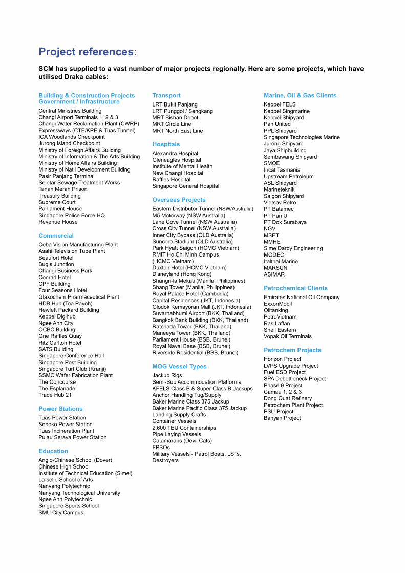
Project references:
SCM has supplied to a vast number of major projects regionally. Here are some projects, which have utilised Draka cables:
Transport
LRT Bukit PanjangLRT Punggol / SengkangMRT Bishan DepotMRT Circle LineMRT North East Line
Hospitals
Alexandra HospitalGleneagles HospitalInstitute of Mental HealthNew Changi HospitalRaffles HospitalSingapore General Hospital
Overseas Projects
Eastern Distributor Tunnel (NSW/Australia)M5 Motorway (NSW Australia)Lane Cove Tunnel (NSW Australia)Cross City Tunnel (NSW Australia)Inner City Bypass (QLD Australia)Suncorp Stadium (QLD Australia)Park Hyatt Saigon (HCMC Vietnam)RMIT Ho Chi Minh Campus (HCMC Vietnam)Duxton Hotel (HCMC Vietnam)Disneyland (Hong Kong)Shangri-la Mekati (Manila, Philippines)Shang Tower (Manila, Philippines)Royal Palace Hotel (Cambodia)Capital Residences (JKT, Indonesia)Glodok Kemayoran Mall (JKT, Indonesia)Suvarnabhumi Airport (BKK, Thailand)Bangkok Bank Building (BKK, Thailand)Ratchada Tower (BKK, Thailand)Maneeya Tower (BKK, Thailand)Parliament House (BSB, Brunei)Royal Naval Base (BSB, Brunei)Riverside Residential (BSB, Brunei)
MOG Vessel Types
Jackup RigsSemi-Sub Accommodation PlatformsKFELS Class B & Super Class B JackupsAnchor Handling Tug/SupplyBaker Marine Class 375 JackupBaker Marine Pacific Class 375 Jackup Landing Supply CraftsContainer Vessels2,600 TEU ContainershipsPipe Laying VesselsCatamarans (Devil Cats)FPSOsMilitary Vessels - Patrol Boats, LSTs, Destroyers
Marine, Oil & Gas Clients
Keppel FELSKeppel SingmarineKeppel ShipyardPan UnitedPPL ShipyardSingapore Technologies MarineJurong ShipyardJaya ShipbuildingSembawang ShipyardSMOEIncat TasmaniaUpstream PetroleumASL ShipyardMarineteknikSaigon ShipyardVietsov PetroPT BatamecPT Pan UPT Dok SurabayaNGVMSETMMHESime Darby EngineeringMODECItalthai MarineMARSUNASIMAR
Petrochemical Clients
Emirates National Oil CompanyExxonMobilOiltankingPetroVietnamRas LaffanShell EasternVopak Oil Terminals
Petrochem Projects
Horizon ProjectLVPS Upgrade ProjectFuel ESD ProjectSPA Debottleneck ProjectPhase 9 ProjectCamau 1, 2 & 3Dong Quat RefineryPetrochem Plant ProjectPSU ProjectBanyan Project
Quality Cable for
Draka Group67 plants in 29 countries. Employs 8,200 people
2007 Version 1
Draka Cableteq AustralasiaSingapore Cables Manufacturers Pte Ltd (SCM)
No. 20 Jurong Port Road Jurong Town Singapore 619094Tel: +65 6265 0707 Fax: +65 6265 2226
Draka Cableteq Australasia
Sindutch Cables Manufacturer Sdn Bhd (SCMM)Tel: 606-556-3833 Fax: 606-556-3282
Draka Cableteq Australia Pty Ltd (DCA)Tel: 61-2-6762-5988 Fax: 61-2-6762-5788
CSC Cable Sdn Bhd (CSC)Tel: 606-556-3833 Fax: 606-556-3670
MCI-Draka Cable Co Ltd (MDC)Tel: 662-308-0830 Fax: 662-308-0833
Draka Cableteq Greater China
Draka Cables (Hong Kong) Limited (DCHK)Tel: 852-2410 9229 Fax: 852-2410 9789
Suzhou Draka Cable Co Ltd (SDC)Tel: 86-512-6578 9888 Fax: 86-512-6578 9878