Embed Size (px)
Citation preview
Finite Element Modeling and Analysis of an M855 Cartridge
by Joseph T. South and Larry W. Burton
ARL-TR-3301 September 2004 Approved for public release; distribution is unlimited.

NOTICES
Disclaimers The findings in this report are not to be construed as an official Department of the Army position unless so designated by other authorized documents. Citation of manufacturer’s or trade names does not constitute an official endorsement or approval of the use thereof. DESTRUCTION NOTICE Destroy this report when it is no longer needed. Do not return it to the originator.
Army Research Laboratory Aberdeen Proving Ground, MD 21005-5069
ARL-TR-3301 September 2004 Finite Element Modeling and Analysis of an M855 Cartridge
Joseph T. South and Larry W. Burton Weapons and Materials Research Directorate, ARL
Approved for public release; distribution is unlimited.
ii
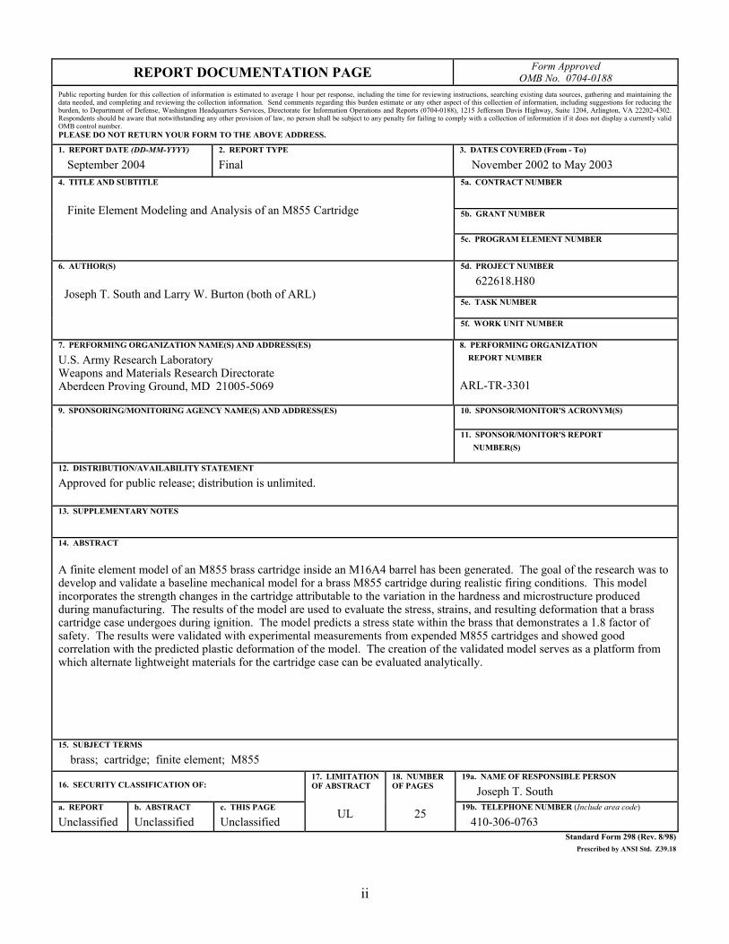
REPORT DOCUMENTATION PAGE Form Approved OMB No. 0704-0188
Public reporting burden for this collection of information is estimated to average 1 hour per response, including the time for reviewing instructions, searching existing data sources, gathering and maintaining the data needed, and completing and reviewing the collection information. Send comments regarding this burden estimate or any other aspect of this collection of information, including suggestions for reducing the burden, to Department of Defense, Washington Headquarters Services, Directorate for Information Operations and Reports (0704-0188), 1215 Jefferson Davis Highway, Suite 1204, Arlington, VA 22202-4302. Respondents should be aware that notwithstanding any other provision of law, no person shall be subject to any penalty for failing to comply with a collection of information if it does not display a currently valid OMB control number. PLEASE DO NOT RETURN YOUR FORM TO THE ABOVE ADDRESS.
1. REPORT DATE (DD-MM-YYYY)
September 2004 2. REPORT TYPE
Final 3. DATES COVERED (From - To)
November 2002 to May 2003 5a. CONTRACT NUMBER
5b. GRANT NUMBER
4. TITLE AND SUBTITLE
Finite Element Modeling and Analysis of an M855 Cartridge 5c. PROGRAM ELEMENT NUMBER
5d. PROJECT NUMBER
622618.H80
5e. TASK NUMBER
6. AUTHOR(S)
Joseph T. South and Larry W. Burton (both of ARL)
5f. WORK UNIT NUMBER
7. PERFORMING ORGANIZATION NAME(S) AND ADDRESS(ES)
U.S. Army Research Laboratory Weapons and Materials Research Directorate Aberdeen Proving Ground, MD 21005-5069
8. PERFORMING ORGANIZATION REPORT NUMBER
ARL-TR-3301
10. SPONSOR/MONITOR'S ACRONYM(S) 9. SPONSORING/MONITORING AGENCY NAME(S) AND ADDRESS(ES)
11. SPONSOR/MONITOR'S REPORT NUMBER(S)
12. DISTRIBUTION/AVAILABILITY STATEMENT
Approved for public release; distribution is unlimited.
13. SUPPLEMENTARY NOTES
14. ABSTRACT
A finite element model of an M855 brass cartridge inside an M16A4 barrel has been generated. The goal of the research was to develop and validate a baseline mechanical model for a brass M855 cartridge during realistic firing conditions. This model incorporates the strength changes in the cartridge attributable to the variation in the hardness and microstructure produced during manufacturing. The results of the model are used to evaluate the stress, strains, and resulting deformation that a brass cartridge case undergoes during ignition. The model predicts a stress state within the brass that demonstrates a 1.8 factor of safety. The results were validated with experimental measurements from expended M855 cartridges and showed good correlation with the predicted plastic deformation of the model. The creation of the validated model serves as a platform from which alternate lightweight materials for the cartridge case can be evaluated analytically.
15. SUBJECT TERMS
brass; cartridge; finite element; M855
16. SECURITY CLASSIFICATION OF: 19a. NAME OF RESPONSIBLE PERSON
Joseph T. South a. REPORT
Unclassified b. ABSTRACT
Unclassified c. THIS PAGE
Unclassified
17. LIMITATIONOF ABSTRACT
UL
18. NUMBER OF PAGES
25
19b. TELEPHONE NUMBER (Include area code)
410-306-0763 Standard Form 298 (Rev. 8/98)
Prescribed by ANSI Std. Z39.18

iii
Contents
List of Figures iv
List of Tables iv
1. Introduction 1
2. Approach 1
3. Material Input and Model Generation 3 3.1 Material Properties ..........................................................................................................3 3.2 Finite Element Model Mesh ............................................................................................6 3.3 Applied Load...................................................................................................................7 3.4 Applied Boundary Conditions.........................................................................................9 3.5 Solution Control ............................................................................................................10
4. Results 10 4.1 Model Validation...........................................................................................................15
5. Summary 16
6. References 17
Distribution List 18
iv
List of Figures
Figure 1. CAD drawing of an M855 cartridge inside the chamber of an M16A2. (The unsupported region of the cartridge is shown in the inset.) .......................................................2
Figure 2. Complete 2-D axisymmetric FEA brass cartridge model showing all components........3 Figure 3. Hardness gradient for an M855 brass cartridge (1). ........................................................4 Figure 4. Stress-strain tensile data for 70-30 alpha brass at different levels of cold rolling,
recrystallization, and re-rolling..................................................................................................5 Figure 5. Compressive stress-strain curve for cartridge brass. .......................................................6 Figure 6. Chamber and projectile base pressure for an M855 cartridge.........................................8 Figure 7. Plot of the internal pressure gradient in Pascals applied to the M855 cartridge. ............8 Figure 8. Applied boundary conditions. .........................................................................................9 Figure 9. Predicted mid-thickness stresses along the length of the cartridge. ..............................11 Figure 10. Plot of the Von Mises stress state in Pascals in the neck and shoulder region of
the cartridge at maximum ballistic pressure. ...........................................................................11 Figure 11. Predicted mid-thickness strain along the length of the cartridge. ...............................12 Figure 12. Predicted mid-thickness failure criteria along the length of the cartridge...................12 Figure 13. Plot of the axial stresses in pascals near the extractor groove.....................................13 Figure 14. Plot of the Von Mises factor of safety for the brass cartridge.....................................13 Figure 15. Predicted versus the measured radial plastic deformation along the length of the
cartridge. ..................................................................................................................................16
List of Tables
Table 1. Results of varying levels of cold rolling, recrystallization and re-rolling on the hardness and modulus of 70-30 alpha brass (4,5).....................................................................4
1
1. Introduction
The use of brass for cartridge cases has a long history and is particularly embedded into the culture of ammunition for small arms. For more than 100 years, brass has served adequately and admirably as a material for cartridge cases. Its relatively high strength and ductility provide it with the twofold ability to withstand large rupture pressures while undergoing deformations that provide the means to seal combustion gases in the chamber. These properties have made brass the intuitively obvious material of choice for cartridge applications.
However, more recently, interest in ammunition weight reduction has increased and therefore, investigations into materials other than the high-density brass have arisen. In order to adequately assess alternate lightweight materials for cartridges, it is first necessary to understand the performance of brass in this role. It was with this thought that an effort was undertaken to employ modern finite element techniques to represent the behavior of brass cartridges.
Interestingly enough, despite the long history of brass usage, little information was found in the literature that reported about the mechanical properties of “cartridge brass,” a copper alloy composed of 70% copper and 30% zinc. This report details the literature findings and specifies those extrapolations that were required to provide a complete characterization of the material over the full range of strains encountered.
The over-arching goal of this exercise was to establish a modeling technique for cartridge cases, which could be validated against the limited data available during realistic firing conditions. The M855 brass cartridge in an M16A4 barrel was selected for this purpose. The results of the model are used to evaluate the stress, strains, and resulting deformation that a brass cartridge case undergoes during operation. The technique was validated by experimental measurements from expended M855 cartridges. With this baseline, the technique can be used to assess other materials and geometries and investigate the influence of temperature, pressure, and firing rate. It is the authors’ intent for this to be the first in a series of reports that investigate these various parameters.
2. Approach
A finite element model was constructed that included the brass cartridge with primer inside the chamber of an M16A2 rifle. The geometry of the cartridge, primer, barrel, barrel extension and bolt was obtained from the manufacturer’s drawings (1,2). The drawings were entered into computer-aided design (CAD) software so that they could be made proportional and for application of the tolerances. The conceptual dimensions of all the components were used.
2
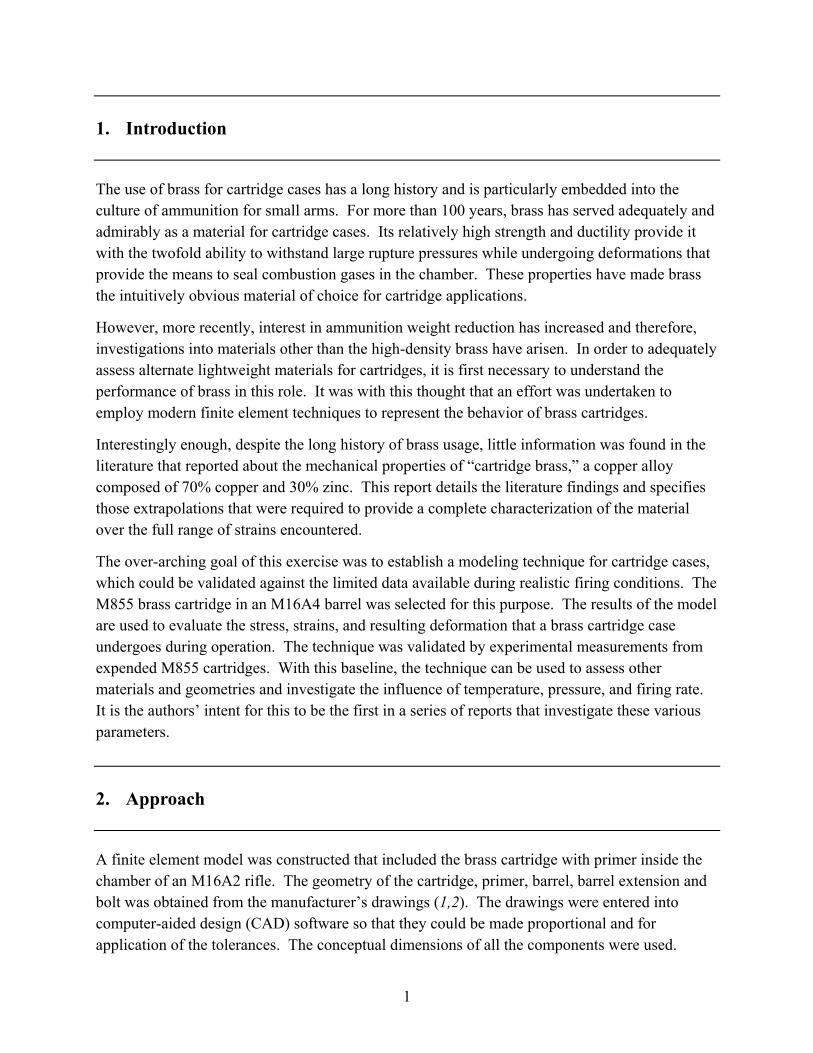
A cutaway CAD drawing of an M855 cartridge set inside the chamber is shown in figure 1. In the figure, the cartridge is shown in intimate contact with the chamber wall. Included in the figure is the barrel extension. One feature to note is the length of the unsupported region near the head of the cartridge. This unsupported region is necessary to allow for the motion of the bolt and the engagement of the extractor pin with the extractor grooves.
Figure 1. CAD drawing of an M855 cartridge inside
the chamber of an M16A2. (The unsup-ported region of the cartridge is shown in the inset.)
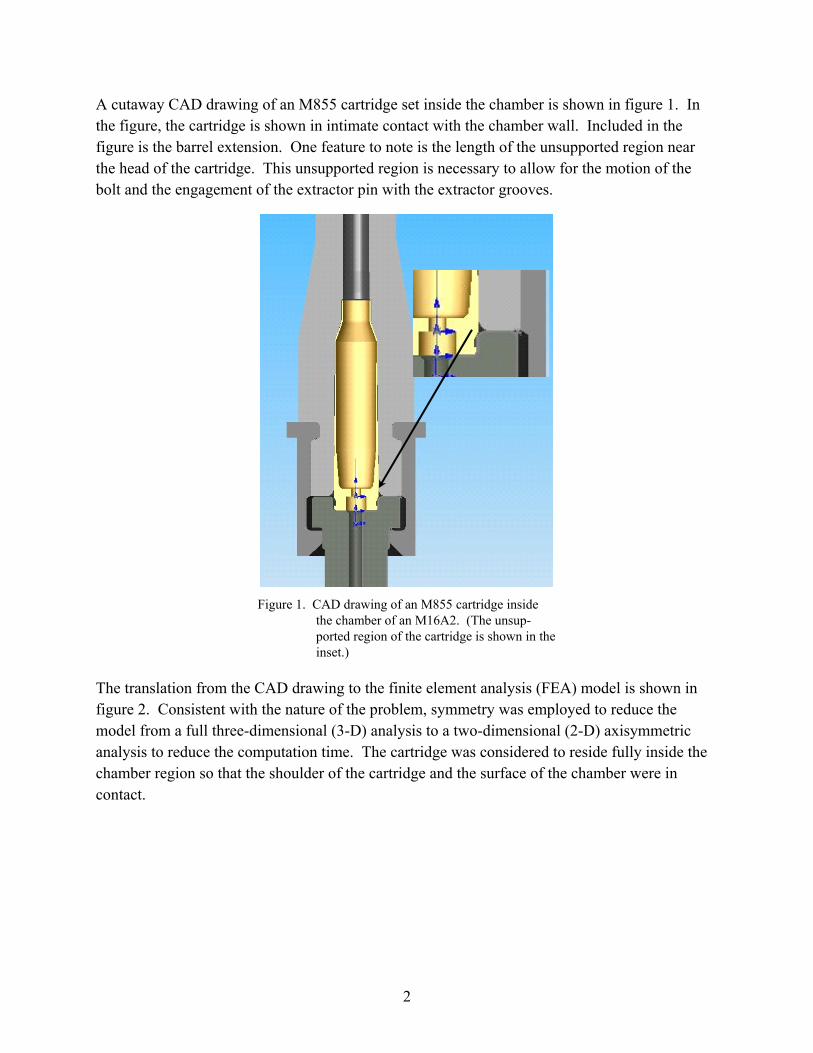
The translation from the CAD drawing to the finite element analysis (FEA) model is shown in figure 2. Consistent with the nature of the problem, symmetry was employed to reduce the model from a full three-dimensional (3-D) analysis to a two-dimensional (2-D) axisymmetric analysis to reduce the computation time. The cartridge was considered to reside fully inside the chamber region so that the shoulder of the cartridge and the surface of the chamber were in contact.
3
Figure 2. Complete 2-D axisymmetric
FEA brass cartridge model showing all components.
3. Material Input and Model Generation
In order to develop an accurate model, realistic material properties and boundary conditions that mimic the actual cartridge and operating conditions were required. This information was obtained through experimental data and an empirical approach.
3.1 Material Properties
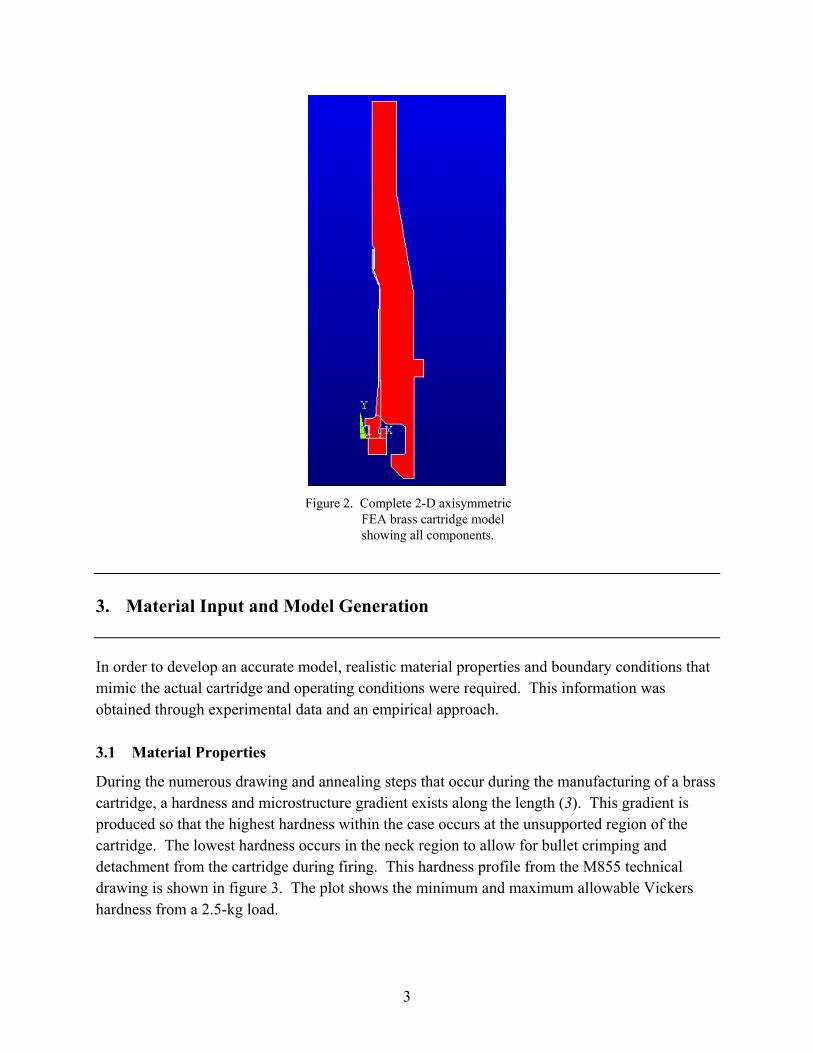
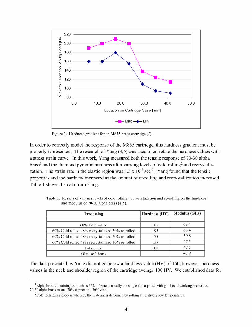
During the numerous drawing and annealing steps that occur during the manufacturing of a brass cartridge, a hardness and microstructure gradient exists along the length (3). This gradient is produced so that the highest hardness within the case occurs at the unsupported region of the cartridge. The lowest hardness occurs in the neck region to allow for bullet crimping and detachment from the cartridge during firing. This hardness profile from the M855 technical drawing is shown in figure 3. The plot shows the minimum and maximum allowable Vickers hardness from a 2.5-kg load.
4
80
100
120
140
160
180
200
220
0.0 10.0 20.0 30.0 40.0 50.0
Location on Cartridge Case [mm]
Vic
kers
Har
dnes
s, 2
.5 k
g Lo
ad [H
V]
Max Min
Figure 3. Hardness gradient for an M855 brass cartridge (1).
In order to correctly model the response of the M855 cartridge, this hardness gradient must be properly represented. The research of Yang (4,5) was used to correlate the hardness values with a stress strain curve. In this work, Yang measured both the tensile response of 70-30 alpha brass1 and the diamond pyramid hardness after varying levels of cold rolling2 and recrystalli-zation. The strain rate in the elastic region was 3.3 x 10⁻⁴ sec-1. Yang found that the tensile properties and the hardness increased as the amount of re-rolling and recrystallization increased. Table 1 shows the data from Yang.
Table 1. Results of varying levels of cold rolling, recrystallization and re-rolling on the hardness and modulus of 70-30 alpha brass (4,5).
Processing Hardness (HV) Modulus (GPa)
60% Cold rolled 185 63.4 60% Cold rolled 48% recrystallized 30% re-rolled 195 63.4 60% Cold rolled 48% recrystallized 20% re-rolled 175 59.8 60% Cold rolled 48% recrystallized 10% re-rolled 155 47.5
Fabricated 100 47.5 Olin, soft brass 47.9
The data presented by Yang did not go below a hardness value (HV) of 160; however, hardness values in the neck and shoulder region of the cartridge average 100 HV. We established data for
1Alpha brass containing as much as 36% of zinc is usually the single alpha phase with good cold working properties;
70-30 alpha brass means 70% copper and 30% zinc. 2Cold rolling is a process whereby the material is deformed by rolling at relatively low temperatures.
5
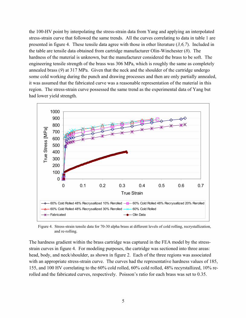
the 100-HV point by interpolating the stress-strain data from Yang and applying an interpolated stress-strain curve that followed the same trends. All the curves correlating to data in table 1 are presented in figure 4. These tensile data agree with those in other literature (3,6,7). Included in the table are tensile data obtained from cartridge manufacturer Olin-Winchester (8). The hardness of the material is unknown, but the manufacturer considered the brass to be soft. The engineering tensile strength of the brass was 306 MPa, which is roughly the same as completely annealed brass (9) at 317 MPa. Given that the neck and the shoulder of the cartridge undergo some cold working during the punch and drawing processes and then are only partially annealed, it was assumed that the fabricated curve was a reasonable representation of the material in this region. The stress-strain curve possessed the same trend as the experimental data of Yang but had lower yield strength.
0100200300400500600700800900
1000
0 0.1 0.2 0.3 0.4 0.5 0.6 0.7
True Strain
True
Stre
ss [M
Pa]
60% Cold Rolled 48% Recrysallized 10% Rerolled 60% Cold Rolled 48% Recrysallized 20% Rerolled
60% Cold Rolled 48% Recrysallized 30% Rerolled 60% Cold Rolled
Fabricated Olin Data
Figure 4. Stress-strain tensile data for 70-30 alpha brass at different levels of cold rolling, recrystallization,
and re-rolling.
The hardness gradient within the brass cartridge was captured in the FEA model by the stress-strain curves in figure 4. For modeling purposes, the cartridge was sectioned into three areas: head, body, and neck/shoulder, as shown in figure 2. Each of the three regions was associated with an appropriate stress-strain curve. The curves had the representative hardness values of 185, 155, and 100 HV correlating to the 60% cold rolled, 60% cold rolled, 48% recyrstallized, 10% re-rolled and the fabricated curves, respectively. Poisson’s ratio for each brass was set to 0.35.
6
The barrel and barrel extension were assumed to be linear elastic steel with a modulus of 200 GPa and Poisson’s ratio of 0.3. No material properties were available for the primer. It was assumed that the primer possesses the same structural characteristics as the head region of the cartridge, with a hardness of 185 HV. The overall FEA model geometry consisted of five different areas and four different material properties.
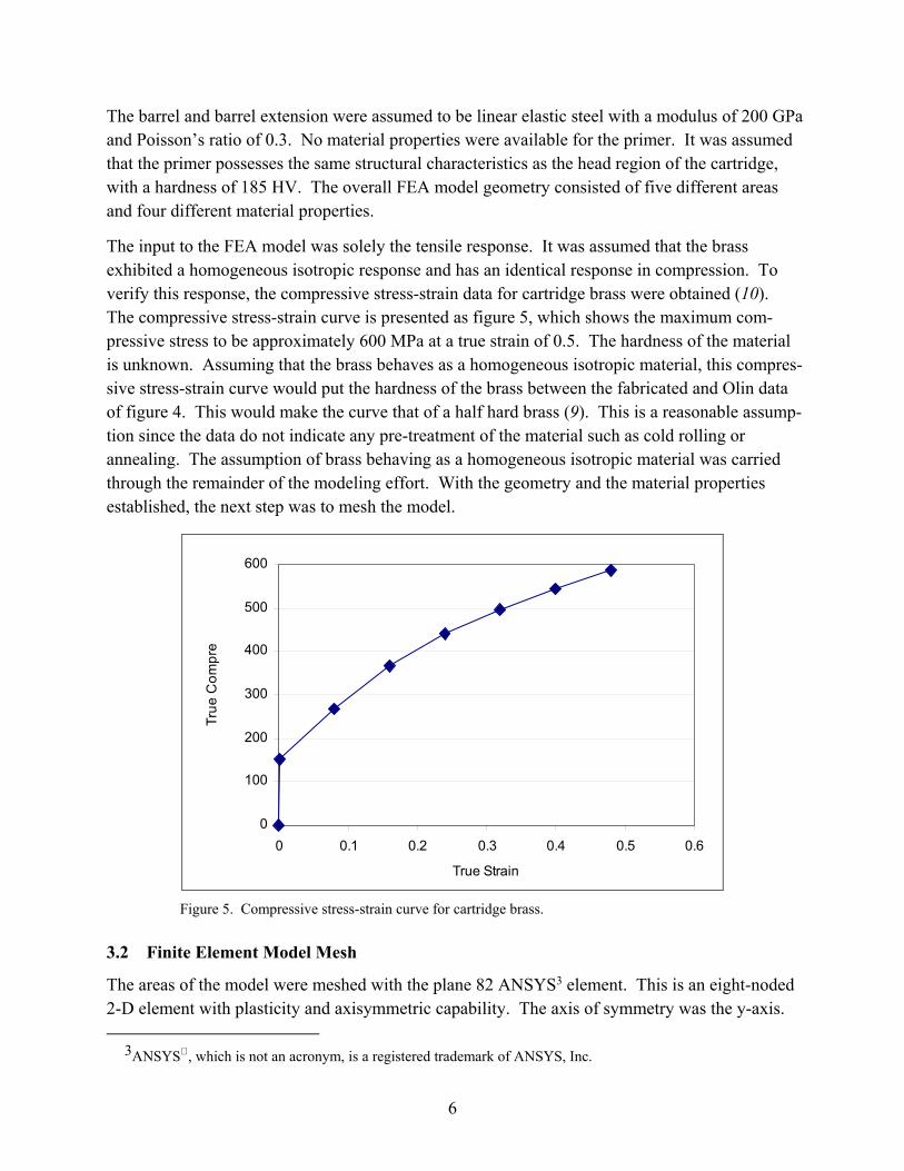
The input to the FEA model was solely the tensile response. It was assumed that the brass exhibited a homogeneous isotropic response and has an identical response in compression. To verify this response, the compressive stress-strain data for cartridge brass were obtained (10). The compressive stress-strain curve is presented as figure 5, which shows the maximum com-pressive stress to be approximately 600 MPa at a true strain of 0.5. The hardness of the material is unknown. Assuming that the brass behaves as a homogeneous isotropic material, this compres-sive stress-strain curve would put the hardness of the brass between the fabricated and Olin data of figure 4. This would make the curve that of a half hard brass (9). This is a reasonable assump-tion since the data do not indicate any pre-treatment of the material such as cold rolling or annealing. The assumption of brass behaving as a homogeneous isotropic material was carried through the remainder of the modeling effort. With the geometry and the material properties established, the next step was to mesh the model.
0
100
200
300
400
500
600
0 0.1 0.2 0.3 0.4 0.5 0.6
True Strain
True
Com
pre
Figure 5. Compressive stress-strain curve for cartridge brass.
3.2 Finite Element Model Mesh
The areas of the model were meshed with the plane 82 ANSYS3 element. This is an eight-noded 2-D element with plasticity and axisymmetric capability. The axis of symmetry was the y-axis.
3ANSYS , which is not an acronym, is a registered trademark of ANSYS, Inc.
7
All four materials (the steel and three different brasses) were modeled with isotropic linear elastic properties. Plasticity of the brass was modeled with the isotropic Mises (11) plasticity model. To use this model, the entire stress-strain curve for each respective brass was entered. Given that the stress-strain curves were in true stress and strain units, the large displacement option was invoked. This option requires that all input be in true stress and strain and output of the results be expressed similarly.
Contact pairs were added to model the interaction along the cartridge-chamber wall and the cartridge-primer interfaces. The contact pair between the cartridge and the chamber allowed for the expansion of the cartridge against the chamber during the combustion event. The pair between the cartridge and the primer modeled the interaction of the interface as well as provided the ability to have the primer to be press fit into the cartridge. ANSYS models contact pairs by allowing the user to specify a target and a contact surface. We modeled the interference fit between the primer and the cartridge by providing an offset to the contact surface so that the contact and target surfaces of the pair were in a mathematical penetration. This penetration resulted in a compression fit of the primer cup into the head of the cartridge case.
3.3 Applied Load
Load was applied to the model as an internal pressure obtained from experimental measurements (12). The pressure at the base of the projectile was calculated with the Lagrangian correction for the pressure gradient down the bore (13). This relation is shown as equation 1.
p
cb
Mc
PP
21+
= , (1)
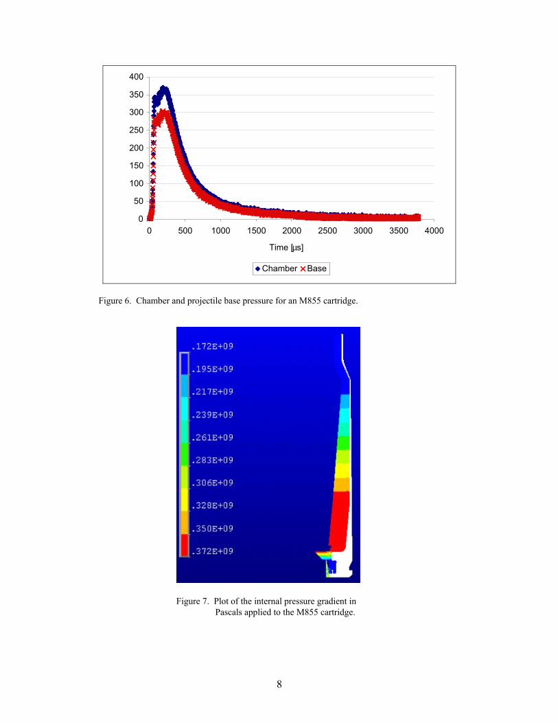
in which Pc is the pressure in the chamber, Pb is the pressure at the base of the projectile, c is the mass of the charge, and Mp is the mass of the projectile. The calculated base pressure and the experimentally obtained chamber pressure applied in the FEA model are plotted in figure 6.
It was assumed that the pressure in the primer cavity was less than the maximum chamber pressure because of the short duration of the pulse. As a result, the pressure in the primer cavity was chosen to be the same as the base pressure in figure 6. The meshed model of the cartridge showing the applied maximum pressure loading is presented in figure 7.
8
0
50
100
150
200
250
300
350
400
0 500 1000 1500 2000 2500 3000 3500 4000
Time [µs]
Chamber Base
Figure 6. Chamber and projectile base pressure for an M855 cartridge.
Figure 7. Plot of the internal pressure gradient in Pascals applied to the M855 cartridge.
9
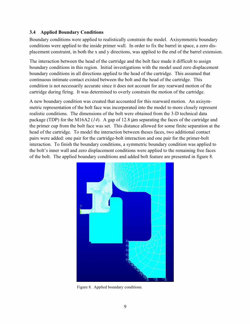
3.4 Applied Boundary Conditions Boundary conditions were applied to realistically constrain the model. Axisymmetric boundary conditions were applied to the inside primer wall. In order to fix the barrel in space, a zero dis-placement constraint, in both the x and y directions, was applied to the end of the barrel extension.
The interaction between the head of the cartridge and the bolt face made it difficult to assign boundary conditions in this region. Initial investigations with the model used zero displacement boundary conditions in all directions applied to the head of the cartridge. This assumed that continuous intimate contact existed between the bolt and the head of the cartridge. This condition is not necessarily accurate since it does not account for any rearward motion of the cartridge during firing. It was determined to overly constrain the motion of the cartridge.
A new boundary condition was created that accounted for this rearward motion. An axisym-metric representation of the bolt face was incorporated into the model to more closely represent realistic conditions. The dimensions of the bolt were obtained from the 3-D technical data package (TDP) for the M16A2 (14). A gap of 12.8 µm separating the faces of the cartridge and the primer cup from the bolt face was set. This distance allowed for some finite separation at the head of the cartridge. To model the interaction between theses faces, two additional contact pairs were added: one pair for the cartridge-bolt interaction and one pair for the primer-bolt interaction. To finish the boundary conditions, a symmetric boundary condition was applied to the bolt’s inner wall and zero displacement conditions were applied to the remaining free faces of the bolt. The applied boundary conditions and added bolt feature are presented in figure 8.
Figure 8. Applied boundary conditions.
10
3.5 Solution Control
The finite element model was solved as a 2-D axisymmetric static model with large displacement effects. The large displacement effects were used since all the data for the cartridge brass were in terms of true stress and strain. To facilitate convergence, the internal pressure load curves of figure 6 were broken into 22 separate loading steps. Automatic time stepping was employed to decrease the running time of the model. Initial loads on the model resulting from the contact pairs were linearly increased in order to achieve convergence.
4. Results
The finite element model was post-processed to obtain the stress and strain through the mid-thickness of the cartridge at the peak pressure as well as the plastic displacement that occurred because of the applied load. Generalized stress plots were produced to determine the areas of high stress generated during the peak internal pressure. A maximum stress failure criterion was chosen to determine the relative distance from failure. The equation is
1.. >=σ
σUltimateCF (2)
in which σUltimate is the ultimate tensile strength and σ is the stress in the system. For cases when the stress was negative, the ultimate compressive strength was used. Failure is assumed to occur when the failure criterion equals unity. The factor of safety that existed within the cartridge because of the applied load was determined by the equation
1.. >=Applied
AllowedSFσσ
(3)
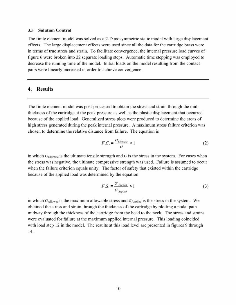
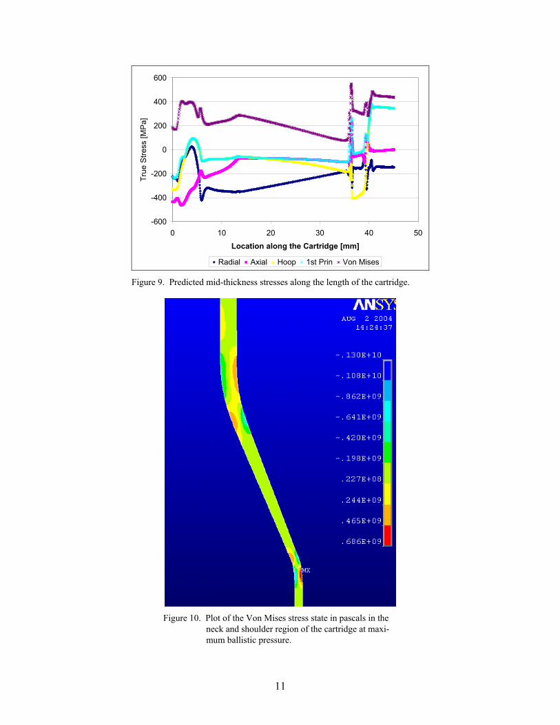
in which σAllowed is the maximum allowable stress and σApplied is the stress in the system. We obtained the stress and strain through the thickness of the cartridge by plotting a nodal path midway through the thickness of the cartridge from the head to the neck. The stress and strains were evaluated for failure at the maximum applied internal pressure. This loading coincided with load step 12 in the model. The results at this load level are presented in figures 9 through 14.
11
-600
-400
-200
0
200
400
600
0 10 20 30 40 50
Location along the Cartridge [mm]
True
Stre
ss [M
Pa]
Radial Axial Hoop 1st Prin Von Mises Figure 9. Predicted mid-thickness stresses along the length of the cartridge.
Figure 10. Plot of the Von Mises stress state in pascals in the
neck and shoulder region of the cartridge at maxi-mum ballistic pressure.
12
-0.02
-0.01
0
0.01
0.02
0.03
0.04
0.05
0.06
0.07
0.08
0 10 20 30 40 50Location along the Cartridge [mm]
True
Stra
in
Radial Axial Hoop 1st Prin Von Mises
Figure 11. Predicted mid-thickness strain along the length of the cartridge.
-1
-0.8
-0.6
-0.4
-0.2
0
0.2
0.4
0.6
0 10 20 30 40 50
Location along the Cartridge [mm]
Failu
re C
riter
ia
Fa-X Fa-Y Fa-Z Fa-Von Mises
Figure 12. Predicted mid-thickness failure criteria along the length of the cartridge.
13
Figure 13. Plot of the axial stresses in pascals near the extractor groove.
0
2
4
6
8
10
12
14
16
0 10 20 30 40 50Location along the Cartridge [mm]
Fact
or o
f Saf
ety
FS-Von Mises Figure 14. Plot of the Von Mises factor of safety for the brass cartridge.
14
The predicted true stresses through the mid-thickness of the cartridge wall are presented in figure 9. The radial, axial, and hoop stresses are largely compressive. This stress state is attributable to the expansion of the cartridge against the chamber wall during pressurization as well as the rearward movement of the cartridge during firing. The transition from the unsup-ported region of the cartridge (figure 1) to the supported is marked by the stress redistribution from a tensile stress to a compressive stress in all three components between 4 and 6 mm. The triaxial stress state remains compressive until the onset of the shoulder in the cartridge at roughly 36 mm from the base. At this location, the triaxial stress state becomes rather complex because of bending within the cartridge to conform to the chamber dimensions. The outer diameter (OD) of the cartridge is in compression while the interior diameter (ID) of the cartridge is in tension. This stress state is shown in figure 10. Between the onset of the shoulder and the onset of the neck, the cartridge is in a triaxial state of compression. At the onset of the shoulder, a bending of the cartridge occurs again. The stress state within these bending regions results in spikes within the mid-thickness plots of figures 9 and 11. These spikes are an artifact of post-processing the model as the nodal path used to produce the curves overlaps these complex stress states and the points are interpolated from the model results.
Within the neck of the cartridge, the brass is in compression in the radial and axial directions; however, the cartridge undergoes a tensile load in the hoop direction. This tensile load is a result of a nominal gap between the cartridge and the chamber ID of 71 µm. The magnitude of this gap is discussed in section 4.1 in relation to the experimental verification of this modeling.
The mid-thickness strains are presented in figure 11. The results complement those of figure 9 with the triaxial strain state following the same pattern as the stresses. The spike in the strain plot at 36 mm is an artifact of the nodal path. The maximum strain obtained with the cartridge occurs in the neck region with a Von Mises strain of 2.5%. The high strains that occur in this area will be exploited in the experimental validation of the model.
The failure criterion of equation 2, which is plotted in figure 12, was calculated so that if a stress component were compressive, it would be evaluated against the compressive strength of figure 5, and if a stress component were tensile, it would be evaluated against the tensile strength of figure 4. The maximum strength failure criteria of equation 2 show that the cartridge’s axial stresses approach 76% of their ultimate, 2 mm from the base. This location corresponds to the extractor groove in the cartridge. Axial stresses are highly compressive because of a combina-tion of the reduction in radius to accommodate the extractor and the cartridge being forced rearward during firing against a stationary bolt face. A graphic of these stresses near the extractor groove is presented as figure 13. The failure criterion achieves the highest tensile values at 40% of ultimate in the neck of the overall cartridge.
The factory of safety of the brass cartridge is presented in figure 14. Because of the complex stress state within the cartridge, only the Von Mises stress was evaluated to calculate the factor of safety. The factor of safety varied along the length of the cartridge, achieving a maximum

15
11.5 before the onset of the neck of the cartridge. The minimum factor of safety observed within the cartridge was 1.8 which occurred within the bending region of the neck.
4.1 Model Validation
The modeling effort evaluated the stress and strains within the cartridge and compared them to criteria to evaluate their acceptability. In order to validate the model, the numerical results were compared to measurements from expended cartridges. With the model, sensitivity analysis was performed to determine the effect of the tolerances on the response of the brass cartridge. Two FEA models were created: one with a minimum cartridge OD to maximum chamber ID toler-ance (maximum clearance) and one with a maximum cartridge OD to minimum chamber ID tolerance (minimum clearance). The models were evaluated with the previously discussed approach, and the predicted radial plastic deformation in the cartridge was evaluated. Fourteen expended brass cartridges were measured to determine their change in radius in the neck because of firing. The firing history of the measured cartridges was unknown but their manufacture stamp linked them to production at Lake City Army Ammunition Plant, Independence, Missouri, in 1989. The change in the radius of the cartridges was evaluated from the ideal cartridge dimension.
Figure 15 shows the results of the sensitivity analysis. The measured radial displacement from the expended cartridges falls between the minimum and maximum bore tolerances. The onset of the plastic deformation coincides with the shoulder region of the cartridge. Increasing the bore diameter increases the magnitude of the plastic deformation and shifts the onset of that deforma-tion rearward toward the base of the cartridge. There is a minor amount of predicted plastic deformation near the end of the unsupported region, 6 and 7 mm from the base. The magnitude of these values was approximately 1 µm. These magnitudes could not be accurately measured on the expended cartridge because of the taper of the cartridge OD and the generic location of the prediction. The most accurate and reliable measurements could only be obtained on the neck of the cartridge. Measurements from the expended M855 cartridges show good correlation with the predicted plastic deformation of the model. This continuity between the predicted and measured deformation validated the modeling effort.
16
-0.01
0
0.01
0.02
0.03
0.04
0.05
0.06
0.07
0.08
0.09
0 10 20 30 40 50Length Along Cartridge [mm]
Rad
ial P
last
ic D
efor
mat
ion
[mm
]
Maximum Clearance PredictionMinimum Clearance PredictionMeasured Cartridge Deformation
Figure 15. Predicted versus the measured radial plastic deformation along the length of the cartridge.
5. Summary
The over-arching goal of this exercise was to establish a modeling technique for cartridge cases that could be validated against the limited data available during realistic firing conditions. The model generated incorporates the strength changes in the cartridge that result from the variation in the hardness and microstructure produced during manufacturing. The results of the model were used to evaluate the stress, strains, and resulting deformation that a brass cartridge case undergoes during operation. The stress and strain were observed to obey expected trends including expansion and bending of the cartridge to conform to the chamber geometry. The model yielded a stress state within the brass that demonstrated a 1.8 factor of safety. The model was validated with experimental measurements from expended M855 cartridges that showed good correlation with the predicted plastic deformation of the model.
The creation of the validated model serves as a platform from which alternate materials for the cartridge case can be evaluated numerically.
17
6. References
1. U.S. ARDEC. M855 Cartridge Drawing, Part No. 9378276, Picatinny Arsenal, NJ, 1984.
2. Primer No. 41 Drawing, Part No. 10534280, U.S. Frankford Arsenal: Philadelphia, PA, 1966.
3. Gibbs L.E. Cold Working of Brass, with Special Reference to Cartridge (70-30) Brass. The American Society for Metals, Cleveland, OH, 1946.
4. Yang C.J. Bend Ductility of 70-30 Alpha Brass I: Observation. Materials Science and Engineering 1989, A112, 1–9.
5. Yang C.J. Bend Ductility of 70-30 Alpha Brass II: Correlation with Tensile Behavior. Materials Science and Engineering 1989, A112, 11–20.
6. Hollomon J.H. Tensile Stress-Strain Curves of a 70-30 Brass; Memorandum Report 630/7-2; Watertown Arsenal: Watertown, MA, October 1944.
7. Saunders D.S. The Low Temperature Annealing of 7.62 mm Brass Cartridge Cases: Stress Corrosion Susceptibility; MRL-R-778; Defence Science and Technology Organisation Materials Research Laboratories: Melbourne, Victoria, 1980.
8. Stehlin, Rick. Data from Olin-Winchester, East Alton, IL, December 2002.
9. Materials Selector 1990, Materials Engineering, December 1989, 94, Cleveland, OH.
10. U.S. Army Materiel Command. Engineering Design Handbook, Ammunition Series, Section 4; Pamphlet AMCP 706-247; Washington, DC, 1964, 160-161.
11. Wagoner R.H. Plastic Behavior of 70/30 Brass Sheet. Metallurgical Transactions A 1982, 13A, 1941–1500.
12. U.S. ARDEC. Data of M855 Cartridges fired from M16A2, Picatinny Arsenal, NJ, 2002.
13. Corner J. Theory of the Interior Ballistics of Guns; John Wiley & Sons Inc.: New York, 282, 1950.
14. U.S. ARDEC. 3-D Technical Data Package for the M16A2, Picatinny Arsenal, NJ, 2003.
18
NO. OF COPIES ORGANIZATION * ADMINISTRATOR DEFENSE TECHNICAL INFO CTR ATTN DTIC OCA 8725 JOHN J KINGMAN RD STE 0944 FT BELVOIR VA 22060-6218 *pdf file only 1 DIRECTOR US ARMY RSCH LABORATORY ATTN IMNE AD IM DR MAIL & REC MGMT 2800 POWDER MILL RD ADELPHI MD 20783-1197 1 DIRECTOR US ARMY RSCH LABORATORY ATTN AMSRD ARL CI OK TECH LIB 2800 POWDER MILL RD ADELPHI MD 20783-1197 1 DIRECTOR US ARMY RESEARCH LAB ATTN AMSRD ARL SE R H WALLACE 2800 POWDER MILL RD ADELPHI MD 20783-1197 2 DIRECTOR US ARMY RESEARCH LAB ATTN AMSRD ARL SS SE DS R REYZER R ATKINSON 2800 POWDER MILL RD ADELPHI MD 20783-1197 7 DIR US ARMY RESEARCH LAB ATTN AMSRD ARL WM MB M BERMAN A ABRAHAMIAN M CHOWDHURY A FRYDMAN T LI W MCINTOSH E SZYMANSKI 2800 POWDER MILL RD ADELPHI MD 20783-1197 1 COMMANDER US ARMY MATERIEL CMD ATTN AMXMI INT 5001 EISENHOWER AVE ALEXANDRIA VA 22333-0001 3 CDR US ARMY ARDEC ATTN AMSTA AR CC M PADGETT J HEDDERICH H OPAT PICATINNY ARSENAL NJ 07806-5000 3 CDR US ARMY ARDEC ATTN AMSTA AR FSA A WARNASH B MACHAK M CHIEFA PICATINNY ARSENAL NJ 07806-5000
NO. OF COPIES ORGANIZATION 6 CDR US ARMY ARDEC ATTN AMSTA AR CCL F PUZYCKI R MCHUGH D CONWAY E JAROSZEWSKI M CLUNE R SCHLENNER PICATINNY ARSENAL NJ 07806-5000 3 CDR US ARMY ARDEC ATTN AMSTA AR CCL A F DINDL C JOHNSON D WITKOWSKI PICATINNY ARSENAL NJ 07806-5000 2 CDR US ARMY ARDEC ATTN AMSTA AR CCL B R MAZESKI J MIDDLETON PICATINNY ARSENAL NJ 07806-5000 1 PM MAS ATTN SFAE AMO MAS PICATINNY ARSENAL NJ 07806-5000 1 PM MAS ATTN SFAE AMO MAS CHIEF ENGINEER PICATINNY ARSENAL NJ 07806-5000 4 PM MAS ATTN SFAE AMO MAS MC F HANZL R KOWALSKI R GULLIFER G DEROSA PICATINNY ARSENAL NJ 07806-5000 1 PM MAS ATTN SFAE AMO MAS PS PICATINNY ARSENAL NJ 07806-5000 2 PM MAS ATTN SFAE AMO MAS LC PICATINNY ARSENAL NJ 07806-5000 2 PM MAS ATTN SFAE AMO MAS MC PICATINNY ARSENAL NJ 07806-5000 3 US ARMY TACOM-ARDEC ATTN AMSTA AR CCI V SCHISSLER K SPIEGEL R TRAUB PICATINNY ARSENAL NJ 07806-5000 1 OFC OF NAVAL RESEARCH ATTN J CHRISTODOULOU ONR CODE 332 800 N QUINCY ST ARLINGTON VA 22217-5600
19
NO. OF COPIES ORGANIZATION 1 NSWC DAHLGREN DIV CODE G06 DAHLGREN VA 22448 1 US ARMY COLD REGIONS RSCH & ENGRNG LAB ATTN P DUTTA 72 LYME RD HANOVER NH 03755 3 NASA LANGLEY RESEARCH CTR ATTN AMSRD ARL VS W ELBER MS 266 F BARTLETT JR MS 266 G FARLEY MS 266 HAMPTON VA 23681-0001 2 ALLIANT TECHSYSTEMS ATTN C CANDLAND R DOHRN 5050 LINCOLN DR MINNEAPOLIS MN 55436-1097 6 ALLIANT TECHSYSTEMS INC ATTN C AAKHUS MN11 2830 B SEE MN11 2439 N VLAHAKUS MN11 2145 S HAGLUND MN11 2439 M HISSONG MN11 2830 D KAMDAR MN11 2830 600 SECOND ST NE HOPKINS MN 55343-8367 3 AAI CORP ATTN DR N B MCNELLIS W ENGEL P SHIPLEY PO BOX 126 HUNT VALLEY MD 21030-0126 4 ARROW TECH ASSOC ATTN J SEIWERT 1233 SHELBURNE RD STE 8 SOUTH BURLINGTON VT 05403-7700 ABERDEEN PROVING GROUND 1 DIRECTOR US ARMY RSCH LABORATORY ATTN AMSRD ARL CI OK (TECH LIB) BLDG 4600 3 DIR USARL ATTN AMSRD ARL SL BB AMSRD ARL SL BL AMSRD ARL SL BG BLDG 328
NO. OF COPIES ORGANIZATION 2 DIR USARL ATTN AMSRD ARL WM JILL SMITH J MCCAULEY BLDG 4600 1 DIR USARL ATTN AMSRD ARL WM B T KOGLER BLDG 4600 1 DIR USARL ATTN AMSRD ARL WM BA D LYON BLDG 4600 3 DIR USARL ATTN AMSRD ARL WM BC P PLOSTINS J NEWILL A ZIELINSKI BLDG 390 3 DIR USARL ATTN AMSRD ARL WM BD B FORCH R PESCE-RODRIGUEZ B RICE BLDG 4600 2 DIR USARL ATTN AMSRD ARL WM BD P CONROY C LEVERITT BLDG 390 2 DIR USARL ATTN AMSRD ARL WM BE R LIEB M LEADORE BLDG 4600 1 DIR USARL ATTN AMSRD ARL WM BF S WILKERSON BLDG 390 2 DIR USARL ATTN AMSRD ARL WM RP J BORNSTEIN C SHOEMAKER BLDG 1121 1 DIR USARL ATTN AMSRD ARL WM M B BURNS J BEATTY BLDG 4600 2 DIR USARL ATTN AMSRD ARL WM MA S MCKNIGHT L GHIORSE BLDG 4600
20
NO. OF COPIES ORGANIZATION 21 DIR USARL ATTN AMSRD ARL WM MB B FINK J BENDER T BOGETTI L BURTON R CARTER K CHO W DE ROSSET G DEWING R DOWDING W DRYSDALE R EMERSON D HENRY D HOPKINS R KASTE L KECSKES B POWERS D SNOHA J SOUTH M STAKER J SWAB J TZENG BLDG 4600 7 DIR USARL ATTN AMSRD ARL WM MC R BOSSOLI S CORNELISON D GRANVILLE B HART F PIERCE E RIGAS W SPURGEON BLDG 4600 14 DIR USARL ATTN AMSRD ARL WM MD E CHIN B CHEESEMAN P DEHMER R DOOLEY G GAZONAS S GHIORSE M KLUSEWITZ J LASALVIA J MONTGOMERY W ROY J SANDS S WALSH D SPAGNUOLO S WOLF BLDG 4600 1 DIR USARL ATTN AMSRD ARL WM TA W GILLICH BLDG 309 9 DIR USARL ATTN AMSRD ARL WM TA M BURKINS B GOOCH T HAVEL C HOPPEL E HORWATH T MOYNIHAN M NORMANDIA J RUNYEON M ZOLTOSKI BLDG 393 1 DIR USARL ATTN AMSRD ARL WM TB P BAKER BLDG 309 1 DIR USARL ATTN AMSRD ARL WM TC R COATES W BRUCHEY BLDG 309
NO. OF COPIES ORGANIZATION 4 DIR USARL ATTN AMSRD ARL WM TD D DANDEKAR M RAFTENBERG S SCHOENFELD T WEERASOORIYA BLDG 4600 2 DIR USARL ATTN AMSRD ARL WM TE A NIILER J POWELL BLDG 120