Embed Size (px)
Citation preview

510
Int. J. Mech. Eng. & Rob. Res. 2014 Abhishek Patil et al., 2014
FINITE ELEMENT ANALYSIS OF IC ENGINECONNECTING ROD BY ANSYS
R A Savanoor1, Abhishek Patil2*, Rakesh Patil3 and Amit Rodagi2
*Corresponding Author: Abhishek Patil,[email protected]
Connecting rod is the intermediate link between the piston and the crank. And is responsible totransmit the push and pull from the piston pin to crank pin, thus converting the reciprocatingmotion of the piston to rotary motion of the crank. Generally connecting rods are manufacturedusing carbon steel and in recent days aluminum alloys are finding its application in connectingrod. In this work we are comparing the von mises stress and total deformation of 2 differentaluminium alloys with the forged steel. FEA analysis was carried out by considering threematerials. The parameters like von misses stress, and displacement were obtained from ANSYSsoftware. Then Compared the aluminium alloys with the forged steel. Then Al5083 alloy found tohave less weight. It resulted in reduction of 63.19% of weight.
Keywords: Connecting rod, Reciprocating motion, Von mises stress, ANSYS
INTRODUCTIONThe connecting rod connects the piston to thecrankshaft and they form a simple mechanismthat converts linear motion into rotary motion.The maximum stress occurs in the connectingrod near the piston end due to thrust of thepiston. The tensile and compressive stressesare produced due to gas pressure, andbending stresses are produced due tocentrifugal effect and eccentricity. So theconnecting rods are designed generally of I-section to provide maximum rigidity with
ISSN 2278 – 0149 www.ijmerr.comVol. 3, No. 3, July 2014
© 2014 IJMERR. All Rights Reserved
Int. J. Mech. Eng. & Rob. Res. 2014
1 Mechanical Engineering Bldea’s PGH College, Bijapur.2 Department of Machine Design, Bldea’s PGH College, Bijapur.3 Department of Machine Design, AIT, Banglore, India.
minimum weight. The maximum stressproduced near the piston end can bedecreased by increasing the material near thepiston end.
The connecting rod is the connectionbetween the piston and the crankshaft. It joinsthe piston pin with the crankpin; small end ofthe connecting rod is connected to the pistonand big end to the crank pin. The function ofthe connecting rod is to convert linear motionof the piston into rotary motion of thecrankshaft. The lighter connecting rod and the
Research Note

511
Int. J. Mech. Eng. & Rob. Res. 2014 Abhishek Patil et al., 2014
piston greater than resulting power and lessthe vibration because of the reciprocatingweight is less. The connecting rod carries thepower thrust from piston to the crank pin andhence it must be very strong, rigid and also aslight as possible. There are two types of smallend and big end bearings. Connecting rodsare subjected to fatigue due to alternatingloads.
In the case of four stroke engines, duringcompression and power strokes theconnecting rod is subjected to compressiveloads and during the last part of the exhaustand the beginning of the suction strokes, totensile loads. In double acting steam engines,during the forward stroke the connecting rodis subjected to compressive load and duringthe return stroke, to tensile load. Connectingrod materials must have good fatigue andshock resistances. Connecting rods forautomotive applications are typicallymanufactured by forging from either wroughtsteel or powdered metal. They could also becast. However, castings could have blow-holeswhich are detrimental from durability andfatigue points of view. The fact that forgingsproduce blow-hole-free and better rods givesthem an advantage over cast rods. Betweenthe forging processes, powder forged or dropforged, each process has its own pros andcons. Powder metal manufactured blanks havethe advantage of being near net shape,reducing material waste. However, the cost ofthe blank is high due to the high material costand sophisticated manufacturing techniques.With steel forging, the material is inexpensiveand the rough part manufacturing process iscost effective. Bringing the part to finaldimensions under the tight tolerance results in
high expenditure for machining, as the blankusually contains more excess material.
LITERATURE REVIEWFor the optimization study, Serag et al. (1989)developed approximate mathematicalformulae to define connecting rod weight andcost as objective functions and also theconstraints. The optimization was achievedusing a Geometric Programming technique.Constraints were imposed on thecompression stress, the bearing pressure atthe crank and the piston pin ends. Fatigue wasnot addressed. The cost function wasexpressed in some exponential form with thegeometric parameters.
Webster et al. (1983) performed threedimensional finite element analysis of a high-speed diesel engine connecting rod. For thisanalysis they used the maximum compressiveload which was measured experimentally, andthe maximum tensile load which is essentiallythe inertia load of the piston assembly mass.The load distributions on the piston pin endand crank end were determined experimentally.They modelled the connecting rod capseparately, and also modelled the boltpretension using beam elements and multipoint constraint equations.While investigatinga connecting rod failure that led to a disastrousfailure of an engine.
Hippoliti (1993) reported designmethodology in use at Piaggio for connectingrod design, which incorporates an optimizationsession. However, neither the details ofoptimization nor the load under whichoptimization was performed were discussed.Two parametric FE procedures using 2D planestress and 3D approach developed by the

512
Int. J. Mech. Eng. & Rob. Res. 2014 Abhishek Patil et al., 2014
author were compared with experimentalresults and shown to have good agreements.The optimization procedure they developedwas based on the 2D approach.
Sarihan and Song (1990), for theoptimization of the wrist pin end, used a fatigueload cycle consisting of compressive gas loadcorresponding to maximum torque and tensileload corresponding to maximum inertia load.Evidently, they used the maximum loads in thewhole operating range of the engine. To designfor fatigue, modified Goodman equation withalternating octahedral shear stress and mean
octahedral shear stress was used. Foroptimization, they generated an approximatedesign surface, and performed optimizationof this design surface. The objective andconstraint functions were updated to obtainprecise values. This process was repeated tillconvergence was achieved. They alsoincluded constraints to avoid fretting fatigue.The mean and the alternating components ofthe stress were calculated using maximum andminimum values of octahedral shear stress.Their exercise reduced the connecting rodweight by nearly 27%.
Figure 1: Model of the Connecting Rod is Shown Below
Figure 2: Fine Mesh Model is Shown Below

513
Int. J. Mech. Eng. & Rob. Res. 2014 Abhishek Patil et al., 2014
Figure 3: All the Degree of Freedom are Constrained at the Crank End
Figure 4: Loading is Done on Piston End (Compressive Loading)
Figure 5: Von Mises Stress for 43926.42 N (Compressive) Al5083 Alloy

514
Int. J. Mech. Eng. & Rob. Res. 2014 Abhishek Patil et al., 2014
Figure 6: Von Mises Stress for 43926.42 N (Compressive) Al6061-T6
Figure 7: Von Mises Stress for 43926.42 N (Compressive) Forged Steel
Figure 8: Total Deformation for 43926.42 N Al5083 Alloy
515
Int. J. Mech. Eng. & Rob. Res. 2014 Abhishek Patil et al., 2014
CONCLUSION• From the above analysis we can conclude
that stresses of all the materials are almostcomparable and also in safe limit, i.e., wellbelow the yield stress.
• Weight of the connecting rod can bereduced by repacing currently using forgedsteel in kirloskar engine by aluminium5083alloy.
• The section modulus of the connecting rodshould be high enough to prevent highbending stresses due to inertia forces,
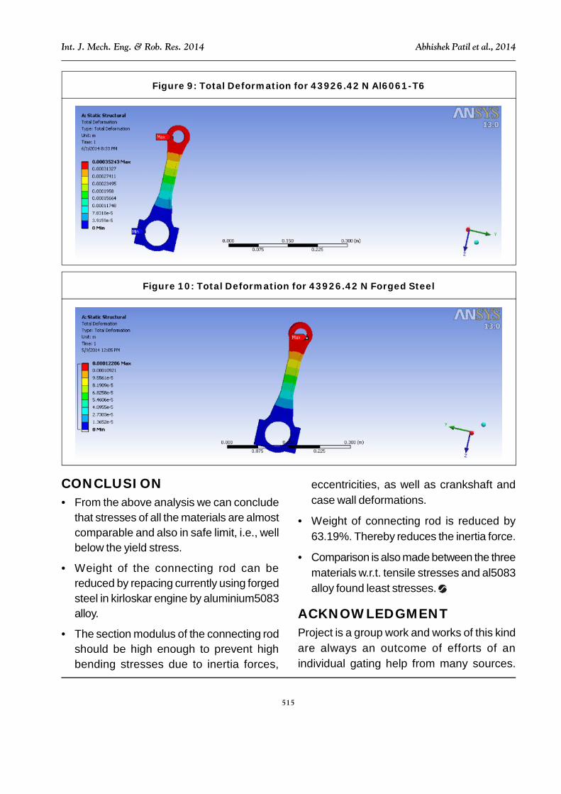
Figure 9: Total Deformation for 43926.42 N Al6061-T6
Figure 10: Total Deformation for 43926.42 N Forged Steel
eccentricities, as well as crankshaft andcase wall deformations.
• Weight of connecting rod is reduced by63.19%. Thereby reduces the inertia force.
• Comparison is also made between the threematerials w.r.t. tensile stresses and al5083alloy found least stresses.
ACKNOWLEDGMENTProject is a group work and works of this kindare always an outcome of efforts of anindividual gating help from many sources.

516
Int. J. Mech. Eng. & Rob. Res. 2014 Abhishek Patil et al., 2014
Beside from our own efforts without theguidance of faculty members and friends wewould not have been able to complete thisproject work successfully. Course of thisproject work and the encouragement given tous throughout our stay in the institution isrememberable.
We are extremely thankful to all the staffmembers of our Mechanical Dept. for givingus good support, suggestions during labtiming. Finally we are thankful to each andeveryone who have helped directly or indirectlyresponsible for successful completion of ourproject work.
Foremost we would like to express ourdeep sense of gratitude to our respected andbeloved principal Dr. V P Huggi, for providingnecessary facilities.
We are extremely thankful to our HOD andour Guide Prof. R A Savanur for guidance,constant enthusiasm and watchful supervisionthroughout the project.
REFERENCES1. Adila Afzal and Ali Fatemi (2003), “A
Comparative Study of Fatigue Behaviorand Life Predictions of Forged Steel andPM Connecting Rods”, SAE International.
2. Augugliaro G and Biancolini M E (2010),“Optimisation of Fatigue Performance ofa Titanium Connecting Rod”, ISPESL,Italy.
3. Charkha P G and Jaju S B (2009),“Analysis & Optimization of ConnectingRod”, 2nd International Conference onEmerging Trends in Engineering andTechnology, ICETET-09.
4. Hippoliti R (1993), “FEM Method forDesign and Optimization of ConnectingRods for Small Two-Stroke Engines”,Small Engine Technology Conference,pp. 217-231.
5. Repgen B (1998), “Optimized ConnectingRods to Enable Higher EnginePerformance and Cost Reduction”, SAETechnical Paper Series, Paper No.980882.
6. Sarihan V and Song J (1990),“Optimization of the Wrist Pin End of anAutomobile Engine Connecting Rod withan Interference Fit”, Journal ofMechanical Design, Transactions of theASME, Vol. 112, pp. 406-412.
7. Serag S, Sevien L, Sheha G and El-Beshtawi I (1989), “Optimal Design of theConnecting Rod”, Modelling, Simulationand Control, B, Vol. 24, No. 3, pp. 49-63,AMSE Press.
8. Shenoy P S (2004), “Dynamic LoadAnalysis and Optimization of ConnectingRod”, May, Masters Thesis, University ofToledo.
9. Webster W D, Coffell R and Alfaro D(1983), “A Three Dimensional FiniteElement Analysis of a High Speed DieselEngine Connecting Rod”, SAE TechnicalPaper Series, Paper No. 831322.
10. Yoo Y M, Haug E J and Choi K K (1984),“Shape Optimal Design of an EngineConnecting Rod”, Journal ofMechanisms, Transmissions, andAutomation in Design, Transactions ofASME, Vol. 106, pp. 415-419.