Embed Size (px)
DESCRIPTION
bill of quantities
Citation preview

File no. EI-D-GA002/7/2014-GA
ERNET India
(An Autonomous Society under Department of Electronics & Information Technology),
Govt. of India)
10th
Floor, Jeevan Prakash Building
25 KG Marg,
New Delhi - 110001
Tender document
for
BALANCE ELECTRICAL, FIRE ALARM, LOW SIDE HVAC, FIRE
SUPPRESSION, PARTITIONING AND INTERIOR WORK
AT
5TH
FLOOR, Block-1,
DMRC IT PARK,
SHASTRI PARK, DELHI
05.09.2014

LETTER SUBMITTING TENDER
To,
THE REGISTRAR & CPO
ERNET India
25 KG MARG,
JEEVAN PRAKASH BUILDING
NEW DELHI - 110001
Dear Sir.
With reference to the tender invited by you for the work.
I/ We hereby offer to execute the work under contract at the respective rates mentioned in the schedule of
quantities.
I/ We have seen the site, understood the site condition, general conditions of contract & special
conditions.
I/ We agree to execute the work as per specifications, general conditions of contract & special conditions.
I/ We deposit earnest money - by demand draft/ pay order which amount shall not carry any interest. I/we
do hereby agree that the sum shall be forfeited by the bank in event our tender is accepted & I/We fail to
execute the contract when required to do so.
Yours faithfully,
(Contractor) Signature of partner/prop. of the firm. In the
presence of our banker
INVITATION OF TENDER
MEMORANDUM OF WORK

ERNET India, an Autonomous Scientific Society under Department of Electronics & Information
Technology, Govt. of India, is a Class `A’ Internet Service Provider for the Education and Research
community in India.
2. We intend to carry out the Balance Electrical Work, Fire Alarm System, HVAC, Plumbing work
and Interior and Partitioning work in our premises at DMRC, Shastri Park, 5th Floor. Bill of Material and
Technical specification are enclosed as Annexure I and Annexure II (A,B &C) for your reference.
Therefore, sealed tenders are invited to carry out Balance Electrical Work, Fire Alarm System, HVAC,
Fire Suppression and Interior and Partitioning work at out premises i.e. 5th Floor, DMRC Building,
Shastri Park, Delhi – 110053.
3. Kindly depute your representative to inspect the premises before submitting your
quotation, if you so desire.
4. Kindly submit your sealed quotation strictly as per Annexure – I and Annexure II(A,B &C) to
the undersigned by 25.09.2014 at 3:00 PM, failing which it would be assumed that you are not interested.
Quotations will be opened on the same day at 03.30 PM. 5. Quotations should be submitted in two separate sealed covers. First cover indicating, “COVER
FOR TECHNICAL SPECIFICATION” should consist of (i) Tender fee of Rs. 2000/- (in case the tender
document is downloaded from ERNET’s Website) (ii) EMD of Rs. 1.00 Lac as per para ; (iii) documents as
per eligibility criteria detailed below; (iv) unpriced bill of material alongwith technical specifications of the
products offered along with literature, pamphlets, drawings etc. Price column in this cover should be kept
blank. Second cover indicating, “COVER FOR PRICE BID” should consist the same details of first cover
as well as price details also. Both the covers should first be sealed separately, and then both the covers
should be kept in a single sealed bigger cover. This cover addressed by name to the officer signing this
enquiry should be submitted to ERNET India, 10th Floor, Jeevan Prakash Building, 25 KG Marg, New
Delhi – 110001 at or before 3.00 PM on 25.09.2014. Bids will be opened on the same day at 3.30 PM on
25.09.2014. If the office happens to be closed on the date of receipt of the tenders as specified, the tender
will be received and opened on the next working day at the same time and venue.
6. All the prospective bidders may submit their queries regarding the contents of the tender document by
10.09.2014 at 11.00 AM. A Pre bid meeting will be held on 10.09.2014 at 11.00 AM in ERNET India, 10th
Floor, Jeevan Prakash Building, 25 KG Marg, New Delhi – 110001 to deliberate the queries received and
to clarify the issues if any, and to answer the questions on any matter that may be raised at that stage as
stated. Responses to the queries of the bidders will only be uploaded on ERNET’s Website by 15.09.2014.
ERNET India has a right to add any additional information/ alter in the bill of material in the tender
document as a result of pre bid meeting with the prospective bidders.
7. All prospective bidders are advised to refer to ERNET’s website for any update/additional information,
before submission of their bids.
Eligibility Criteria
The bidder can be an organization/ institute/ company/ Corporation/ Society/ Trust/ Firm/
Registered / incorporated in India fullfiling at least the following criteria and must also submit
documentary evidences in support of fulfilling these documents.
(i) The bidder can be a company/ Corporation/ Society / Trust Firm, Registered in India and should be in
existence prior to 01.04.2009. Consortium in any form is not allowed.
(ii) The bidder must have successfully competed at least one project of similar nature for a value not less
than Rs. 80.00 Lacs or two projects of value not less than Rs. 50.00 Lac each or three project of Rs. 40.00
Lac each in the last three years.

II. Documents Establishing Bidders Eligibility:
1. In case bidder is a company- Certified copy of the certificates of incorporations for companies &
Memorandum and articles of association.
Or
In case the bidder is a registered society – Certified copy of registration deed with objects of constitution of
society.
Or
In case bidder is a corporation – Authenticated copy of the parent stature.
Or
In case of proprietary concern – documents authenticating the same
Certified copies of documents submitted, as above, must be signed in ink and carry the seal of the signatory.
2. List of present Directors/ owners/ Executives Council of Members/ trustees/ Board members as
applicable.
3. Copy of Income tax returns filled in last three years.
4. Copy of Service Tax Registration Certificate
5. Audited Balance Sheet and Income Statement for three years of 2010-11, 2011-12 and 2012-13 duly
signed in ink by the authorized signatory of the bidder and his/ her auditor.
6. Any other Documentary evidences (signed in ink by authorized signatory) providing that bidder fulfills
the eligibility criteria.
7. General Information / profile on the bidders company.
General Conditions :
1. This tender has been divided in to (3) three separate parts/ section. First part consists of
Electrification and Fire Alarm System work, (ii) HVAC & Fire suppression systems and (iii) Interior
and Partitioning work. Accordingly, it is informed that bidder has a choice to participate either in
only one or two section or in all sections. L1 bidder will be decided as per individual section i.e. A,B
&C of Annexure II.
2. Bids should be valid for a minimum period of 180 days after the due date.
3. Envelope should bear the inscription
“Quotation for Tender for Balance work of Electrical, Fire Alarm, HVAC, Fire Suppression,
Interior and partitioning work at DRMC Shastri Park
“Tender Enquiry No.: EI-D-GA002/7/2014-GA”
o Tender dated : 05.09.2014
o Pre bid meeting with queries 10.09.2014 at 11.00 AM
o Response to queries 15.09.2014

o Date and Time for submission of Bid 25.09.2014 (3.00 PM)
o “Due Date & Time for Opening of Bids: 25.09.2014 (3.30 PM)
4. The Bids must reach the undersigned on or before the due date. Bids received after the due date &
time i.e. by 25.09.2014 at 3.00 PM is liable to be rejected. In the event of due date being a closed holiday
or declared Holiday for Central Government offices, the due date for submission of the bids will be the
following working day at the appointed time & venue.
5. The rates should be quoted in Indian Rupees for provision of deliverables at the premises of
ERNET India. All prices shall be fixed and shall not be subject to escalation of any description. The rates
must be quoted as per the Performa provided in Annexure-II (A,B & C). Price comparison will be made as
per bill of material specified in individual section of Annexure – II (A,B & C) . L1 for each section will
be decided individually. Hence bidder will be free to quote for any or all sections of Annexure-II.
6. Govt. Levies like sales tax, octroi, WCT etc., if any, shall be paid at actual rates applicable on the
date of delivery. Rates should be quoted accordingly giving the basic price, Sales Tax etc., if any.
7. It may specifically be mentioned whether the quotation is strictly as per tender
specifications/conditions. If not, deviations must be spelt out specifically. In the absence of this, the
quotation would be deemed to be in compliance and the vendor has to accept the conditions as
specified in the tender document.
8. Please give the Registration number of the firm along with the LST/CST/WCT No. allotted by the
concerned authorities in your quotation.
9. ERNET India reserves the right to accept or reject any bid or cancel the tender proceedings without
assigning any reason there of or :
(a) To accept or reject any tender in whole or in part.
(b) To increase or decrease the quantities of any item and bidder has to execute the same
at the rate quoted.
10. Incomplete quotations are liable to be rejected.
11. Bidder shall sign all pages of quotation and drawings forwarded with the quotation.
12. In case of any discrepancy between rates mentioned in figures and words, the latter shall prevail.
13. ERNET India may waive any minor infirmity or may seek any clarification, if so desired.
14. Any attempt of negotiation direct or indirect on the part of the bidder with the authority to whom he
has submitted the tender or authority who is competent finally to accept it after he has submitted his
tender or any endeavor to secure any interest for an actual or prospective bidder or to influence by
any means the acceptance of a particular tender will render the tender liable to be excluded from
consideration.
15. The vendor will have to arrange for all the testing equipment and tools required for installation,
testing, maintenance etc.
16. The vendors should give clause-by-clause compliance for the technical specification of the
equipments in their technical bids.

17. INSPECTION
ERNET India or its representative shall have the right to inspect or to test the items to confirm their
conformity to the ordered specifications. The supplier shall provide all reasonable facilities and
assistance to the inspector at no charge to ERNET India. In case any inspected or tested goods fail
to conform to the specifications, ERNET India may reject them and supplier shall either replace the
rejected goods or make all alterations necessary to meet specification required free of cost to
ERNET India.
18. EARNEST MONEY DEPOSIT
i) Bidder firm should submit the Earnest Money Deposit of Rs.1,00,000/- (Rupees One Lakh
Only) for every section in the form of Demand Draft/Pay Order/Bank Guarantee of any
Nationalized Bank taken in the name of ERNET India, New Delhi. Bank Guarantee should be
valid minimum for a period of 180 days from due date of the quotation. Quotations received
without Earnest Money Deposit are liable to be rejected. Example: if one bidder is
submitting bids against all the 03 section of the tender, the bidder should submit 03 EMD
of Rs. 100,000/- each along with technical bid of respective sections.
ii) Tender fee – Bidder is required to submit Tender fee of Rs. 2000/- alongwith technical
part of the bid. Tender fee will not be refundable.
iii) Security Deposit in the form of Bank guarantee shall be submitted by the Selected vendor
within 15 days after issue of work order. Security deposit shall be 10% of the total cost of
work order. In case of non submission of Security Deposit, the EMD of the selected
bidder will be forfeited in addition to cancellation of Purchase Order.
iv) Performance bank guarantee should be valid for a minimum period of 15 months from
the date of issue of work order.
v) Earnest Money is liable to be forfeited and bid is liable to be rejected, if the bidder withdraw or
amends, impairs or derogated from the tender in any respect within the period validity of the
tender i.e. 180 days.
vi) The earnest money of all the unsuccessful bidders will be returned after placement of order on
the selected vendor. No interest will be payable by ERNET India on the Earnest Money
Deposit.
vii) The Performance bank guarantee of successful bidder shall be returned after successful
delivery, installation, furnishing of material and successful completion of 01 year from the date
of handover of fully furnished site with respect to their section of work.
19. Time limit:
The above said work for all the sections OR any section to be carried out at DMRC premises within one
month (30 Days) from the date of issue of Purchase Order. Contractor should keep in mind that the above
referred work is critical in terms of time frame and should be completed within a prescribed time i.e. 30
days from the date of issue of Purchase Order.
20. Payment terms:
(i) 40% payment will be considered after completion of 50% work at the site with the certification of
Project Implementation Team or by ERNET India authorized consultant.

(ii) 50% payment will be consider edand release after completion of work at the site with the certification
of Project implementation Team or by ERNET Authorized consultant.
(iii) Balance 10% payment will be considered after Defect Liability Period of 9 months (Refer para 23)
from the date of completion of satisfactory work and also after carrying out defect if any observed during
defect liability period.
Special Conditions :
1. Bidder are requested to read the tender documents, general conditions, special Conditions,
drawing, specifications, schedule of quantities, etc. carefully and offer most competitive rate after
visiting site.
2. Contractor in their own interest are advised to visit the site & get themselves familiarize in
the prevailing situations before submitting their rates. No claim whatsoever for ignorance,
misunderstanding shall be entertained later.
3. The contractor shall be responsible for making good in expeditions & workman like manner.
Any defects, which may be found within one years of the handing over the premises, shall have to be
rectified / replaced by the bidder at no additional cost. In case contractor fails to do so, the same would be
got done at his cost & risk. The cost incurred by the ERNET shall be deducted from the PBG or any other
dues.
4. Unit rates shall be quoted in English in figures as well as in words with reference to each item and for
all items shown in the attached schedule of quantities. The amount of each item should be worked out.
5. The tender shall sign and every page of the tender documents including the layout drawings attached
here to.
6. Tender not containing the full particulars as mentioned above or as called for in the special conditions
is liable to summarily rejection.
7. The samples of all the material & work item shall be got approved from the Architect/ competent
authority/ Project Implementation team before proceeding further on the work.
8. The drawing contains sketches showing salient features details at the various scales indicating extent
work & specifications to be followed. These can be modified by the ERNET from time to time in
accordance with technical requirements at the site.
9. Any damage done to the property of the ERNET during execution of the work shall be Responsibility
of the contractor & it shall be made good by him, at his cost to the entire satisfaction of the ERNET
India.
10. ERNET India shall have full power to get the material or workmanship etc. inspected & tested by an
independent agency for its soundness & adequacy.
11. The contractor shall examine all drawings before quoting & commencing of actual work & report to
the Company/ ERNET India any discrepancies for omission & shortcomings in the drawings.
12. The work shall be of highest standard both as regard to material & workmanship. Modern tools &
first-class latest techniques shall be employed for its execution.

13 Sufficiency of Tender
The contractor shall be deemed to have satisfied himself before tendering to the correctness and
sufficiency of his tender for the work and of his prices for the work and of his prices stated in the
schedule, which shall, except in so far as it is otherwise provided in the contract, cover all his obligations
under the contract and all matters and things necessary for the proper completion and maintenance of the
work.
14. Assignment or Sub Letting of Contract
The contractor shall not assign the contract or any part thereof or any benefit or interest therein or there
under or any claim arising out of the contract to any other party without the prior written consent of the
employer.
15. Power to make Alterations
ERNET India shall have power to make any alterations or additions to the stipulated specifications,
drawings, designs, and in instructions that may appeal to him to be necessary or, advisable during the
progress of the work and the contractor shall have no claim for compensation on account of such
alterations or additions. The contractor shall be bound to carry out the work in accordance with any
instructions which may be given to him in writing signed by the implementation committee and such
alterations shall not invalidate the contract and any additional work which the contractor may be directed
to do in the manner above specified as part of the work shall be carried out by the contractor on the same
conditions in all respects on which he agreed to do the main work and at the same rates as are specified in
the tender for the main work.
16. Disruption of Progress
The contractor shall give written notice to ERNET India whenever planning or progress of the works is
likely to be delayed or disrupted unless any further drawings or order, including a direction, instruction or
approval is issued by the Architect/ ERNET India within a reasonable time. The notice shall include
details of the drawing or order required and by when if is required and of any delay or disruption likely to
be suffered if it is late. If, by reason of any failure or inability of the Architect to issue within a time
reasonable in all the circumstances any drawings or order requested by the contractor and the work suffers
delay then the architects shall take such delay into account in determining any extension of time to which
the contractor is entitled under provisions of contract hereof, however no other compensation will be
admissible on this account.
17. Rectification of Defects
if, it shall appear to the Architect/ competent authority or his representative in-charge of the works that
any work any has been executed with unsound, imperfect or un-skillful workmanship or material or any
inferior description, the contractor shall, on demand, in writing from the Architect/ competent authority
specifying the work material or articles complained of shall rectify or remove and reconstruction work so
specified in part, as the case may require.
18. Variation
In case the quantity of any item of the work executed increases by more than 50% from the quantity given
in the tender document, the rate of such item would be settled as under:
a) Rate of the item worked out as per market rate
b) Rate of the item quoted by the contractor.
The rate of such item would be lowest of the two rates mentioned above.

NOTE : The quantity of items may increase or decrease as per the requirement of the site. The
work at the site w.r.t. Interior, HVAC, Plumbing and electrical has been carried out partially.
Before submitting the bid, Vendor may inspect the site and note the balance work to be carried out
at the site. Due to partial work already done at the site, bill of Quantity, queries of bidders and
other specifications/ standard of products shall be discussed and finalized in the pre bid meeting.
19. The contractor shall submit the samples of various materials for the approval of ERNET India or its
representative. The contractor shall use the material only after the approval of ERNET India or its
representative.
20. Free Access to work site
The contractor shall provide all necessary and reasonable facilities and free access to the works and his
records at site of work to ERNET officer or its authorized agency. He shall provide facilities and space to
the satisfaction of ERNET India or his representative for inspection of any part of work.
21. Hindrance Register
A Hindrance Register shall be maintained by the contractor at the site wherein the contractor shall notify
the items affected and the execution of work, the date on which the delay was cleared. These entries shall
be initiated by the ERNET India or his representative.
22. Contradiction between BOQ, Specifications and Drawings:
In the event of conflicts between BOQ, Specifications, Drawings, the BOQ shall take precedence over the
specifications and drawings. Keeping the general intent of the scope of work under said contract, the
Architect/ consultants would interpret the requirement of the design intent & contract and their decision
shall be final and acceptable to all concern including the contractors
23. Defects Liability Period
The contractor shall be responsible to make good and remedy at his own expense within such period as
may be stipulated by the employer any defect which may develop or may be noticed before the expiry of
9 (nine) months from the date of completion and intimation of which has been sent to the contractor
within seven days of the expiry of the said period.
24. Security
Security of all thhe materials and labour at site shall be contractor’s responsibility at his own cost.
25. Fire Certificate
Vendor have to facilitate the Fire Certificate from the Govt. Authority. Charges/ fee in this regard will be
paid by ERNET India as per the Bill of material ( Refer Electrical and Fire Alarm System head Sub Head
“I”)
26. Insurance of staff:
The contractor shall insure all his staff working at site against injury, loss of life etc., and claims of
compensation will be entertained by the owners, employers in this regard.
27. Liquidity damages
If the contractor fails to complete the works within the time for completion stated in the appendix/
elsewhere or within any extended time under Clause here of, the contractor shall pay the employer the
sum at the rate of 1% of the contract value per week of the non-completed works subject to a maximum
limit of 10% of the contract value as Liquidated Damages for the period during which the said works shall
so remain incomplete or the employer may deduct aforesaid sum towards such damages from any monies
due to the Contractor.

28. TERMINATION CLAUSE
Either party i.e. ERNET India or bidder can terminate the service agreement by giving notice in advance.
In case, the bidder stops the work without notice, ERNET India has the right to encash the bank
guarantee.
29. ARBITRATION LAWS
Except where otherwise provided for in the contract, all questions and disputes relating to interpretation
and application of the provisions of the contract shall be settled mutually within thirty (30 days) days (or
such longer period as may be mutually agreed upon) from the date of either party notifies in writing that
such dispute or disagreement exist, under the Rules of India Arbitration and Conciliation Act, 1996. The
venue of arbitration shall be New Delhi, India. The arbitration resolution shall be final and binding upon
the parties and judgement may be entered thereon, upon the application of either party, by any court
having jurisdiction. This contract shall be governed by the Indian laws.
Yours faithfully,
(Bhupal Singh)
Registrar & CPO

Annexure I
Section A Electrical and Fire Alarm System
Specifications for Electrical work
1. SPECIFICATION FOR ELECTRICAL WORK
2. GENERAL SPECIFICATOIN FOR: FIRE ALARM SYSTEM
Fire fighting
Fire clearance from DMRC/ Delhi Fire Service, MICC cabling if required for fire clearance
1.1 SCOPE
1.1 The scope of the contract shall be the design, manufacturer, supply and erection including testing
and commissioning of the entire electrical system including all equipment and accessories, in
accordance with the specifications and documents, at the site of proposed project.
1.2 The general terms & conditions shall form a part of the specifications and documents.
2.0 DESIGN: The Contractor shall design his equipment etc. as per requirements of codes & standards
mentioned in the documents. The tenderers shall submit criteria of design adopted by them along
with the tender.
In general, the contractor shall supply, store, erect, test and commission all the equipment required
for Electrical Installation. The contractor shall furnish all the materials, labour, tools and equipments
for the electrical work, as shown in the accompanying drawings and in the bill of quantities and
specifications hereinafter described.
1.2 CONTRACTOR
The Contractor shall be a licenced electrical contractor, possessing a valid electrical contractor’s
license in the state, employing licensed supervisors and skilled workers having valid permits as per
the Regulation of Indian Electricity Rules and Local Electrical Inspector’s requirements. (In case the
contractor does not have licence of that state then it should be clearly stated through which local
electrical contractor they shall submit the test report & a copy of the valid licence of the contractor
be enclosed along with the copy of their own licence of the state of their registration).
1.3 The installation shall conform in all respects to Indian standard Code of Practice for Electrical
Wiring Installation I.S. - 732 and ‘National Electrical Code’. It shall be in conformity with the
current I.E Rules and Regulations and requirements of the local Electric Supply Authority in-so-far
as these become applicable to the installation. Wherever this specification calls for a higher standard
of materials and/or workmanship then those required by any of the above regulations, these
specifications shall take precedence over the said regulations and standards.

In general, the materials, equipments and workmanship not covered by the above, shall conform to
the following Indian Standards (Latest Edition) unless otherwise called for:
1.3.1 SWITCHGEAR
a. Requirements of A.C. Circuit Breakers. : IS 2516 (Part I) Sec.1,2 & 3 (Part-II)
b. Switches and Switch Isolators above 1000V
But Not Exceeding 1.1 KV : IS 4710
c. Markings & arrangements for switchgear bus-
bars, main connection & auxilliary wiring : IS 375
d. Specifications for normal duty air break
switches & composites unit for air break
switches and fuses for voltage not exceeding
1000 Volts. : IS 4064
e. Heavy duty air-break switches and composite
units of air-break switches and fuses for
voltages not exceeding 1000 Volts. : IS 4047
f. Specification for miniature circuit breakers. : IS 8828
g. Specification for enclosed distribution, fuse
boards and cut-outs for voltage not exceeding
1000 Volts : IS 2675
h. Installation and maintenance of switchgear. : IS 3072 (Part I)
i. HRC cartridge fuse links 650 Volts. : IS 2208
1.3.2 CABLE
a. Specification for paper insulated and lead
sheathed cables : IS 692
b. Code of Practice for installation and
maintenance of paper insulated power cables
(upto and including 33 KV) : IS 1255
c. Specification for PVC insulated (Heavy Duty)
electric cables Part-I for Voltage upto 1100
Volts. : IS 1554
d. Specification for PVC insulated cables (for
voltage upto 1100 V) (Part-II) with Aluminium
conductors. : IS 694 (Part-II)
3. Specification for rigid steel conduit for
electrical wiring. : IS 9537

4. Specifications for rigid non metallic conduits
for electrical installations. : IS 9537
5. Specifications for accessories for rigid steel
conduits for Electrical wiring. : IS 3837
6. Box for the enclosure of electrical accessories
steel and C.I. Boxes. : IS 5133 (Part I)
7. 3Pin plugs and sockets outlets : IS 1293
8. Ceiling Roses : IS 371
9. Adhesive insulating tapes for Electrical
purposes (Part- I & II) : IS 2448
10. General and safety requirements for Electrical
lighting fittings. : IS 1913
11. Watertight electric light fittings. : IS 3553
12. Flood Lights. : IS 1947
13. Ceiling fans and regulators. : IS 374
14. Propeller type AG Ventilating fans : IS 2312
15. Code of Practices for earthing. : IS 3043
16. Glossary of terms for electrical cable and
conductors. : IS 1885
17. Code of Practice for buildings (General)
Electrical installation : IS 1646
18. Protection of buildings and allied structures
against lighting. : IS 2309
19. Current Transformers : IS 2705 (Part-I to III)
20. Voltage Transformer : IS 3156 (Part-I to III)
21. Power Transformer : IS 2026-1977 (Part-I to IV)
22. Installation Transformer : IS 10029
23. Shunt capacitors for Power system : IS 2834
24. Direct acting electrical indicating instruments : IS 1246
25. Factory assembled switchgear : IS 8623
26. Rating for Cable : IS 3961 (Part -II)

27. Earthing : IS 3843
1.4 INSPECTION & APPROVAL OF THE WORK BY LOCAL AUTHORITY
On completion of this work, the contractor shall obtain and deliver to the owners the certificates of
inspection and approval by electrical inspectorate of local Administration. The fees paid for
inspection will be reimbursed on production of challan/receipt. The contractor shall include in his
rates all charges necessary for getting electrical installation approved which includes Sub-station,
LT distribution, etc. by the Chief Electrical Inspector to the state government or/ and from any other
authority required for this job.
1.5 APPLICATION FOR ELECTRIC SUPPLY/ LIASON
The Contractor shall be responsible for filing and follow up application for electric supply to the
project. The contractor shall carry out all the liason work required for obtaining electric supply at
site commencing from filing of application. This liason shall be deemed to be a part of the contract.
2. L. T. PANELS (POWER CONTROL CENTERS & SWITCH BOARD PANELS)
2.1 GENERAL: Medium voltage power control centres (generally termed as switch board panels)
shall be in sheet steel clad cubicle pattern, free floor standing type, totally enclosed,
compartmentalized design. This specification shall cover the following types of panels:
a) Air circuit breaker panels - Drawout type with single or double tier arrangement as per design
shown on the drawings.
b) Panels with one or more Air circuit breakers with Draw-out arrangement and switch-fuse units
of non-drawout design.
c) Panels with switch- fuses of non- drawout type. However, the switch-fuse units can have
drawout fuse-carriage if a particular make of switch-fuse is used.
The panels shall generally be of extensible type with provision for bus extension on or both sides
as desired at the time of approved of shop drawings.
2.2 CODE/STANDARDS :
The panels shall generally conform to the requirements of following codes/ specifications:
a) IS-8623 h) IS-2705
b) IS-4237 i) IS-722
c) IS-2147 j) IS-4064
d) IS-3072 k) IS-2208
e) IS-375 l) IS-6875
f) IS-1248 & 2419 m) IS-6005
g) IS-5082
The equipment shall conform to Indian Electricity Rules as amended up-to-date. The supplier shall
examine the provision of these codes and confirm or indicate his comments.
2.3 CONSTRUCTION:

Power control centres/ switch board panels shall of free standing type, with sheet steel enclosure
having following features :
a) The panel shall be constructed of sheet steel of minimum 2.0 mm thickness. The internal frames
shall be made of structural steel angles or made up sections (as per standard design of the
manufacturer) specifications of which, shall be submitted along with offers.
b) The panel shall be compartmentalised to accommodate one feeder n each compartment. The main
bus bar chamber shall be provided at the top of panel or bottom of the panel as required. The
compartments shall be arranged in section with metallic/ phenol barrier in between.
A vertical cable alley of at least 200mm width shall be provided to serve one/ two vertical section
of feeders. Cable alley shall have hinged door/ doors with rubber gaskets. Suitable cable clamping
arrangement with slotted steel members shall be provided in the cable alley. Similarly, vertical bus
bar shall be housed in-between two feeder compartments in a separate bus chambers. The opening
between bus chamber and feeder compartments shall be properly covered with Bakelite/ Hylam
sheets of 3mm minimum thickness. The vertical bus chamber shall be provided with removable
bolted covers on the front and back side. All the interconnecting links to the feeders shall be
shrouded so as to avoid accidental contact, by means of phenol barriers.
c) Each compartment shall have its own hinged door with concealed hinges. The doors shall have
heavy duty rubber gasket fixed on the inner side of the door. The door shall have interlocking
facility with the feeder unit.
d) The Panel shall have punched openings for mounting meters, lamps, push buttons, relays, etc.
e) The dimensions of feeder compartments, bus chambers and cable alleys shall be as shown on the
relevant drawings. However, the following minimum dimensions shall be strictly adhered to :
i. ACB compartment: Drawout -600mm wide x 1000mm deep x 900mm high.
ii. SWITCH FUSE UNITS/MOULDED CASE CIRCUIT BRACKER (NON-DRAWOUT TYPE) :
Up to 63A/ 100A : 300mm wide x 225mm high x 400mm deep
250A : 400mm wide x 400mm high x 400mm deep
400A to 630A : 400mm wide x 500mm high x 400mm wide.
(or vice- versa).
iii. BUS CHAMBER:
Main bus (Horizontal) : 400mm high x 300mm deep
Vertical bus (Feeder bus) : 300mm wide x 400mm deep
iv. Cable alley : Min. 200mm wide.
These dimensions are furnished as a guide and the clearances required in between each live bus/
link and between bus/ links to the earth (panel wall/ sheet) shall be as per relevant Indian Standard
Code of practice. However, minimum clearance between neutral bus and earth shall not be less
than 25mm. The panel supplier shall furnish detailed sectional drawings and also arrange to get
the panel inspection done at intermediate stages of fabrication to avoid fault defective fabrication
of the panels (however, the compliance of these specifications shall entirely be the suppliers’
responsibility).

2.4 BUS BARS :
a) The bus bars shall be suitable for 3 phase, 4 wire, 415 volts 50 Hz AC supply. The bus bars shall
be made of high conductivity aluminium. The bus bars shall have uniform cross-section
throughout the length. The bus bars shall be designed for carrying rated-current continuosly. The
bus bars and links shall be designed for a maximum temperature of 75OC. The max. current
density of bus bars shall be as follows:
i. Copper : 1.86 Ampere/ Sq.mm. of cross section area.
ii. Aluminium: 1.28 Ampere/ Sq.mm. of cross section area.
It may be noted that these ratings are the upper limit to which the bus could be stressed. Suitable
derating factors shall be applied to arrive at the correct cross section of bus bars.
b. Bus bars shall be supported on suitable non hygroscopic, non combustible, material such as DMC/
SMC at sufficiently close intervals to prevent bus bar sag. All bus bar joints shall be provided with
high tensile steel bolts (electro plated with suitable metal such as Nickel/ Cadmium), spring
washer and nuts so as to ensure good contact. Alternatively, electroplated/ tinned brass bolts shall
be used. The joints shall be formed with fish-plates on either side of bus bar to provide adequate
contact area. Bus supports shall be provided on either side of joints (max. unsupported distance
from the joint 400mm)
c. Power shall be distributed to feeders in dual section by a set of vertical bus bars (Phases+neutral).
Individual module shall be connected to the vertical bus bars through sleeved connections.
d. Bus bars shall be insulated with PVC sleeves (heat shrink type) with colour coding (Red/ Blue/
Yellow/ Black).
e. The bus bars and their supports shall be able to withstand thermal and dynamic stresses due to the
system short-circuits. The supplier shall furnish calculations alongwith his drawing establishing
the adequacy of bus bars both for continuous duty and short -circuit rating. Short circuit withstand
capacity shall be for one second. Calculations for spacing of supporting of supports shall also be
furnished.
2.5 EARTHING: The panels shall be provided with a copper earth bus running throughout the width
of the switchboard. Suitable earthing eyes/bolts shall be provided on the main earthing bus to
connect the same to the earth grid at the site. Sufficient number of star washers shall be provided
at the joints to achieve earth continuity between the panels and the sheet metal parts.
2.6 MOUNTINGS: Panels incorporating switchfuse units shall have suitable compartments of
standard width. Each compartment shall incorporate a heavy duty load break switchfuse and HRC
fuses. Suitable cable termination arrangement shall be provided for switchfuse/ fuse-switch unit
feeders. Equipment shall be provided with proper fastening arrangements to ensure vibration free
operation. Proper designation as given on the respective drawings shall be provided for every
equipment.
Circuit breakers shall be mounted such that they are accessible from the front of the panel. More
than two circuit breakers shall not be incorporated in a vertical section. The breakers compartment

shall be divided into two parts, one for the breaker and the other for incorporating associated
control gear. The necessary instrumentation shall be provided on the door of the compartment.
2.7 INTERLOCKING
The panels shall be provided with the following interlocking arrangements :
a. The door of the feeder compartments is so interlocked with the switch drive or handle that the
door can be opened only if the switch is in “OFF” position. De-interlocking arrangement shall also
be provided for inspection.
b. It shall not be possible for the breakers to be withdrawn when in “ON” position.
c. It shall not be possible for the breakers to be switched “ON” unless it is either in fully inserted
position or for testing purposes it in fully isolated position.
d. The breaker shall be capable of being racked into “testing”, “isolated” and maintenance position
and kept in any of these positions.
e. A safety catch to ensure that the movement of the breaker as it is withdrawn, is checked before it
is completely out of the cubicle shall be provided.
2.8 PROTECTION AND INSTRUMENTATION : Protection and instrumentation shall be as per
standard specification.
2.9 WIRING: All the interconnections between the incoming, bus and the outgoings of 100A and
above rating shall be done by insulated links/ strips of suitable sizes. Switch fuses and equipments
below 100A rating shall be wired with PVC insulated copper conductors. The wiring for
instrumentation protection and control equipment shall be carried out with PVC insulated flexible
copper conductors.
The Power interconnections shall be carried out by means of bolted connections with washers.
The wiring shall be terminated by using crimping sockets. Wring shall be laid out neatly in
bunches which are fastened to the steel members of the panel. All the potential circuits shall be
protected by fuses mounted near the tap-off point from the main connections.
2.10 TERMINALS: All the control, instrumentation and protection wiring shall be provided with
printed PVC ferrules at both ends. For terminating control cables on to the equipment in the
panels, suitable terminals blocks shall be provided. The terminal shall also be numbered for easy
identification and maintenance.
2.11 SURFACE TREATMENT: All sheet metal accessories and components of power, control
centres and switchboard panels shall be thoroughly cleaned, degreased, derusted and phosphatised
before redoxide primer is applied. The panel shall be stove enameled to the required final finish.
The interior surfaces of the panel shall also be painted to required shade. The supplier shall
indicate in his offer, if there is any deviation from the treatment specified above.
2.12 ENCLOSURES: The panel enclosure shall be dust and vermin proof and shall be suitable for
indoor installation. Enclosure design shall be in accordance with the requirements of IP 54 as per

IS-2147-1962. The supplier shall confirm whether this requirement is met and a type test
certificate furnished. If type test certificate for IP-54 is not available, the same shall be brought out
clearly in his offer.
2.13 NAME PLATE: The panel as well as the feeders compartment doors shall be provided with
name plates giving the switchboard/ feeder descriptions as indicated on the drawings.
2.14 TESTING: The power control centres shall be tested at factory after assembling of all
components and completion of all interconnections and wiring. Tests shall be coducted in
accordance with the requirements relevant IS Codes/ specifications.
a. INSULATION TEST
i. Insulation of the main circuit, that is, the insulation resistance of each pole to the earth and
that between the poles shall be measured.
ii. Insulation resistance to earth of all secondary wiring should be tested with 1000V megger.
Insulation test shall be carried out both before and after high voltage test.
b. HIGH VOLTAGE TEST :
A high voltage test with 2.5KV one minute shall be applied between the poles and earth.
Test shall be carried out on each pole in turn with the remaining poles earthed. All units
racked in position and the breakers closed. Original test certificate shall be submitted
along with panel.
3. SPECIFICATION FOR MOULDED CASE CIRCUIT BREAKERS:
3.1 GENERAL : Moulded case circuit breakers or fuse free breaker shall be incorporated in the switch
board wherever specified. MCCBS shall conform to BS: 3871 Part II or JIS-C-8370 in all respects.
MCCBS shall be suitable either for single phase 230V or three phase 415volts.
3.2 CONSTRUCTION : The MCCB and case shall be made of high strength heat resistant and flame
retardant thermo-setting insulating material. Operating handle shall be quick make/quick break, trip-
free type. The operating handle shall have suitable “ON”, “OFF” and “TRIPPED” indicators. Three
phase MCCBS shall have a common operating handle for simultaneous operation and tripping of all
the three phase. Suitable arc extinguishing device shall be provided for each contact. Tripping unit
shall be of thermal-megnetic type provided on each pole and connected by a common trip bar such
that tripping of any one pole actuates three poles to open simultaneously. Thermal
magnetic/tripping device shall have IDMT characteristics for sustained over loads and short circuits.
Contact tips shall be made of suitable are resistant, sintered alloy for long electrical life. Terminals
shall be of liberal design with adequate clearances.
3.3 ACCESSORIES : MCCBS shall be provided with the following accessories, if specified in
schedule of quantities:
i. Under voltage release
ii. Shunt release
iii. Alarm Trip alarm
iv. Auxiliary contacts.

3.4 INTERLOCKING : Moulded case circuit breakers shall be provided with the following
interlocking devices for interlocking the door of switch board:
a. Handle interlock to prevent unnecessary manipulation of the breaker.
b. Door interlock to prevent the door being opened when the breaker is in “ON” position.
c. De-interlocking device to open the door even, if the breaker is in “ON” position.
3.5 RUPTURING CAPACITY: The moulded case circuit breaker shall have a returning capacity of
not less that 10KA Rms at 415 volts. Wherever required, higher rupturing capacity breakers to meet
the system short circuit fault shall be used. All such ratings shall be as per equipment
schedule/B.O.Q.
3.6 TESTING:
a . Original certificate of the MCCBS as per BS:3871 or JS-C-8370 shall be furnished.
b. Pre-commissioning tests on the switch boards panel incorporating the MCCB shall be done
as per specifications.
4. SPECIFICATION FOR METERING, INSTRUMENTATION AND PROTECTION:
4.1 GENERAL: The Specifications hereinafter laid down shall cover all the meters, instrumentation and
protective devices required for the electrical work. The ratings, type and quantity of meters,
instruments and protective devices shall be as per the schedule of quantities and drawings.
4.2 INSTRUMENT TRANSFORMERS
a. Current Transformers :
Current transformers shall be in a conformity with IS:2705 (Part I, II and III) in all respects. All
current transformers used for medium voltage applications shall be rated for 1 KV. Current
transformers shall have rated primary current, rated burden and class of accuracy as specified in
the schedule. However, the rated secondary current shall be 5A unless otherwise specified. The
acceptable minimum class of various applications shall be as given below.
Measuring : Class 0.5 to 1
Protection : Class 5P10
Current transformers shall be capable of withstanding without damage, magnetic and thermal
stresses due to short circuit fault of 35 MVA on medium voltage system. Terminals of the current
transformers shall be paired permanently for easy identification of poles. Current transformers
shall be provided with earthing terminals for earthing chassis frame work and fixed part of the
metal casing (if any).
Current transformers shall be mounted such that they are easily accessible for inspection,
maintenance and replacement. The wiring for CTS shall be copper conductor, PVC insulated
wires with proper termination lugs and wiring shall be bunched with cable straps and fixed to the
panel structure in a neat manner.

4.3 RELAYS:
a. General
Protection relays shall be provided wherever required to trip and isolate the particular section
under fault. All the relays shall be provided with flag type indicators to indicate the cause of
tripping. The flag indicators shall remain in position unit they are resent by hand reset.
Relay shall be designed to make or break the normal circuit current with which they are
associated. The relay contacts shall be of silver or platenium alloy. The contacts shall be designed
to withstand repeated operation without damage. The relays shall be of draw-out to facilitate
testing maintenance Draw-out case shall be dust tight with a finish suitable for tropical country.
The relays shall be capable of disconnecting the faulty section of the net work or fault equipment
without causing interruption or disturbance to the remaining sections. The analysis of setting shall
be made considering relay errors, pick-up and overshoot errors and shall be submitted to the
Engineer/Architect for approval.
b. Over current Relay : Over current relay shall be induction type with inverse definite minimum
time lag charactoristics. The over circuit relays shall be provided with adjustable current and time
settings. The setting for current shall be 50 to 200% in step of 25%. The IDMT over current
relays shall have time lag (delay) of 0 to 3 seconds. The time setting multiplier shall be adjustable
from 0.1 to unity. Over current relays shall be fitted with suitable tripping device with trip coil
being suitable for operation on 5Amp.
c. Earth Fault Relay: Earth fault relay shall have current setting of 10% to 40% in steps of 10%
otherwise, the earth fault relay shall conform to specification laid down for over current relays.
d. Under Voltage Relays : Under Voltage Relays shall be induction type and shall have inverse
limit operation characteristics, with pick up voltage range of 50-90% of the rated voltage.
4.4 TESTING
4.5.1 Instrument transformers shall be tested at factory as per IS: 2705 and IS : 3156. The test shall
incorporate the following:
Routing Tests:
Original test certificates in triplicate shall be provided.
4.5.2 Meters shall be tested as per IS : 1248. The tests shall include routine tests. Original test
certificate in triplicate shall be furnished.
4.5.3 Suitable injection tests shall be applied to the secondary.
a. Circuit of every instrument to establish the correctness of calibration and working order All
relays and protective devices shall be tested to establish the correctness of setting and
operation by introducing a current generator and an ammeter in the circuit.
5. SPECIFICATION FOR POWER FACTOR IMPROVEMENT SYSTEM:

5.1 GENERAL: The Power factor improvement system shall comprise of capacitors and associated
switchgear and control gear as per the requirements.
5.2 CAPACITORS: Power factor correction capacitors shall conform in all respects to IS: 2834-
1964. Capacitors shall have approval of fire insurance association of India. The capacitors shall be
suitable for 3 phase 415 V, at 50 Hz frequency and shall be available in single phase and three
phase units of 5, 10, 15, 20, 25 and 50 KVAR sizes. The capacitors shall be suitable for indoor use
upto ambient temperature of 500 C. The permissible overloads shall be as given below:-
a. Voltage overload shall be 10% for continuous operation and 15% for 6 hours in a 24 hour cycle.
b. Current overload shall be 15% for continuous operation and 50% for 6 hours in a 24 hour cycle.
c. Overload of 30% continuously and 45% for 6 hours in a 24 hour cycle. Capacitors shall be
hermetically sealed in sturdy corrosion proof, sheet steel containers and impregnated with non-
inflammable synthetic liquid. Every element of each capacitor unit shall be provided with its own
built in silvered fuse. The capacitors shall have suitable discharge device to reduce the residual
voltage from crest value of the rated voltage to 50 V or less within one minute after capacitor is
disconnected from the source of supply. The loss factor of capacitor shall not exceed 0.005 for
capacitors with synthetic impregnants. The capacitors shall withstand voltage of 2500 V ac (power
frequency test voltage) for one minute. The insulation resistance between capacitors, terminals and
containers when test voltage of 500V DC is applied shall not be less than 50 megohms.
5.3 CAPACITOR CONTROL PANEL:
The capacitor control panel shall generally comprise of following:
a) Power factor correction relay
b) Step controller with reversing motor.
c) Time delay and no-volt relays.
d) Contactor and fuses for individual capacitor banks.
e) Auto- manual selector switch for either manual or automatic operation.
f) Current Transformers (On main LT Panel)
g) ON/OFF indicating lamps with fuses for each bank
h) ON/OFF Push Buttons for each bank.
5.4 CONTROL PANEL:
The capacitor control panel shall be fabricated out of 2.0 mm sheet steel suitably rust inhibited and
stove enameled. The panel shall have adequate space for mounting the capacitors. The panel shall be
of dust and vermin proof construction with suitable ventilation arrangement for capacitors. Panels
shall be dead front pattern and floor munting type, complete with cabling arrangement, bus bars and
earthing, etc. as per specification No. ELEC- 110/90.
6. SPECIFICATION FOR: MEDIUM VOLTAGE CABLES
6.1 TYPE: Medium voltage cables shall be aluminium conductor, PVC insulated, PVC sheathed and
steel wire armoured or steel tape armoured construction. Aluminium conductors up to 10sq.mm.
may be solid, circular in cross section, and sizes above 10sq.mm. shall be stranded. Sector shaped
stranded conductors shall be used for sizes above 25sq.mm. The cable shall conform to IS 1554
(Part I).

6.2 RATING: The cable shall be rated for a voltage of 650/1100 Volts.
6.3 CONSTRUCTION: The conductors for power cables shall be made of electrical purity
aluminium & that for control cable from annealed high conductivity copper. The conductors shall
be insulated with high quality PVC base compound. A command covering (bedding) shall be
applied over the laid up cores by extrusion or wrapping of a filling material containing
unvulcanized rubber or thermoplastic material, armouring shall be applied over the inner shath of
bedding, over the armouring a tough outer sheath of PVC sheathing shall be extruded. The outer
sheath shall bear the manufacturers name and trade mark at every 30 meter interval.
6.4 CORE IDENTIFICATION :
Core shall be provided with the following colour scheme of PVC insulation.
i. Core : Red/Black/Yellow/Blue
ii. Core : Red and Black
iii. Core : Red, Yellow, and Blue
iv. 3.5/4 core : Red, Yellow, Blue and black.
6.5 CURRENT RATINGS :
The current rating shall be based on the following conditions.
i. Maximum conductor temperature : 70OC
ii. Ambient air temperature : 40OC/50OC
iii. Ground temperature : 70OC
iv. Depth of laying : 75cm
6.6 SHORT CIRCUIT RATING:
Short circuit ratings for the cables shall be as specified in IS : 1554 Part -I.
6.7 SELECTION OF CABLES :
Cables have been selected considering the conditions of the maximum connected load, ambient
temperature, grouping of cables & the allowable voltage drop. However, the contractor shall
recheck the sizes before the cables are fixed and connected to the service.
a. Storing: All the cables shall be supplied in drums. On receipt of cables at site, the cables
shall be inspected and stored in drums with flanges of the cable drums in vertical position.
b. Laying: Cables shall be laid as per the specifications given below. The system adopted for
this job shall be as per BOQ :
i. Duct system
Wherever specified cables shall be laid in underground ducts. The duct system shall
consist of a required number of reinforced “HUME” pipes with simplex joints. Wherever asbestos
cement pipes are used, the pipes shall be enclosed in concrete of 75mm thick, the ducts shall be
properly anchored to prevent any movement. The top surface of the cable ducts shall be laid with
a gradient of atleast 1:300. The ducts shall be provided with inspection manholes and all direction
changes and at required regular intervals for drawing the cable. The manholes shall be of
reinforced concrete either cast-in-situ or precast. The manhole cover and frame shall be of cast

iron and machine finished to ensure a perfect joint. The manhole cover shall be installed flush
with ground or paved surfaces. The duct entry to the man holes shall be made leakproof with
lead-wool joints. The ducts shall be properly plugged at the ends to prevent entry of water
rodents, etc. Suitable duct markers shall be placed along the run of the cable square embedded in
concrete, indicating the voltages, no of ducts and the direction of run of the cable duct. Suitable
cable supports made of angle iron shall be provided in the manholes for supporting the cables.
Proper identification tags shall be provided for each cable in the manholes.
ii. Cables in outdoor trenches:
Cables shall be laid in outdoor trenches wherever called for. The depth of the
trenches shall not less than 75cm from the final ground level. The width of the trench shall not be
less than 45cm. However, where more than one cable is laid, an axial distance of not less than
15cm shall be allowed between the cables. The trenches shall be cut square with vertical side
walls and with uniform depth. Suitable shoring and propping may be done to avoid caving in of
trench walls. The floor of the trench shall be rammed and levelled. The cables shall be laid in
trenches over the rollers placed inside the trench. The cable drum shall be rolled in the direction
of the arrow for rolling. Wherever cables are bent, the minimum bending radius shall not be less
than 12times the diameter of the cable. After the cable is laid and straightened, it shall be covered
with 8cm thick layer of sand. Cable shall then be lifted and placed over this sand. Cable shall then
be lifted and placed over this sand cushion. The cable shall then be covered with a 8 cm. Thick
sand cushion. Over this, a course of cable protection tiles or burnt brick shall be provided to cover
the cables 50mm on either side. Trench shall be backfilled with earth and consolidated. Cables
shall be laid in Hume pipes/ stone-ware pipes at all road crossings and in CI pipes at the wall
entries. Approved cable markers made of aluminium or CI indicating the voltages, no. of cables
and the direction of rep. Of the cables shall be installed at a regular interval of 30 meters.
iii. Cables in indoor treanches :
Cables shall be laid in indoor treanches where specified. The trenches shall be made
of brick masonry with smooth cement mortar finish. The dimensions of the trenches shall be
determined depending upon the maximum number of cables that is expected to be
accommodated. Cables shall be arranged in tier formation inside the trenches. Suitable clamps
hooks and saddles shall be used for securing the cables in position. Spacing between the cables
shall not be less than 15cm centre to centre. Wherever specified, trenches shall be filled with fine
sand and covered with RCC precast slabs or steel chequered covers. Unless otherwise called for
specifically in BOQ, the making of indoor trenches is outside the scope of this work.
iv. Cable on Tray/ Racks:
Cables shall be laid on cable trays/ racks wherever specified. Cable racks/trays shall
be of ladder, trough or channel design suitable for the purposes. The nominal depth of the trays/
racks shall be 150mm. The width of the trays shall be as per the design shown on drawing. The
cable trays shall be made of steel or aluminum. The trays/ racks shall be completed with end
plates, tees, elbows, risers, and all necessary hardware. Steel trays/ Rack shall be painted with two
coats of enamel paint of approved shade over a coat of red oxide primer. Cable trays shall be
erected properly to present a neat and clean appearance. Suitable cleats or saddles made of
aluminum strips with PVC covering shall be used for securing the cables to the cable trays. The
cable trays shall comply with following requirements:
1. The trays shall have suitable strength and rigidity to provide adequate supports for
all contained cables.
2. It shall not present sharp edged, burrs or projections injurious to the insulation of the
wiring/ cables.

3. If made of metal, it shall be adequately protected against corrosion or shall be made
of corrosion resistant material.
4. It shall have side rails or equivalent structural members.
5. It shall include fittings or other suitable means for changes in direction and elevation
of runs.
6.8 INSTALLATION
1. Cable trays shall be installed as a complete system. Trays shall be supported properly from
the building structure. The entire cable tray system shall be rigid.
2. Each run of the cable tray shall be completed before the installation of cables.
3. In portion where additional protection is required, non combustible covers/ enclosures
shall be used.
4. Cable tray shall be exposed and accessible.
7. SPECIFICATION FOR: MEDIUM VOLTAGE DISTRIBUTION BOARDS
7.1 General: Distribution boards for Power & light circuit distribution shall be factory builts & shall be
suitable for 415volts, 3phase or 230 volts single phase supply as specified in BOQ. The distribution
boards shall conform to IS 8623 (for factory built assemblies).
7.2 Makes: Makes of DB’s shall be as per Acceptable Material / Approved List.
7.3 Type: The following boards shall be of cabinet design, totally enclosed and shall provide protection
against ingress to IP 42 of IS 2147. Only those types of DBs which have been type tested and
passed by a national laboratory for IP 42 shall be offered.
However, if none of the type available from the approved makes meets the above requirement,
alternative makes can be offered with technical literature and copy of test certificate.
7.4 Components : Distribution boards shall generally be provided with the following major
components:
a. Miniature circuit breeders
b. Earth leakage circuit breakers
c. Bus Bars
d. Netural links/bus
e. Earth Bus
7.5 Miniature Circuit Breakers : MCBS shall generally conform to IS8828. The breaking capacity of
MCBS shall not be less than 6KA the miniature circuit breakers shall suitable for snap fixing on a
standard DIN rail. The MCBS shall be suitable for operating under full load under ambient
temperature conditions (i.e. -10OC to 55OC in India. MCBS shall have terminals suitable for
receiving aluminium cables of adequate cross section. (up ot 32A rating 16sq.mm. & 40, 50, 63A,

35sq.mm. cable). Three phase MCBS shall have common trip bar so that all the poles make and
break simultaneously.
7.6 Earth Leakage Circuit Breakers: Earth leakage circuit breakers shall be used as incomers in
distribution boards wherever specially called for in BOQ ELCB shall be suitable for incorporation in
standard DB manufactured by the approved manufacturers. ELCBS shall be of core balance type and
shall not cause nuisance tripping. The ELCB shall be rated for 100mA fault circuit tripping. ELCB
shall be provided with a test lamp and push button to test the healthiness of the circuit.
7.7 Bus Bars : The bus bars shall be of copper and duly tinned or plated. The bus bar rating shall be
atleast 100A as per manufacturers design.
Single phase DBS shall have Bus bars shall be solidly anchored with single pole MCBS of specified
ratings. The bus bars shall be fully shrouded. The bus bars shall be able to accept single, double or
triple pole MCBS.
Three phase DBS shall have single piece bus bar and coupling link avoiding drilling and bolting of
bus bars.
However, if the above ‘unique bus bars’ system is not available from the approved manufacturers
alternative makes can be offered with full technical particulars.
7.8 Cabinet: The DB cabinet shall be made of atleast 1.6 mm thick sheet steel duly stove enamelled or
powder coated (as per standard manufacturing product). The cabinet shall be suitable for either
recess mounting or surface mounting.
The cabinet shall be provided with conduit cable entry knock-outs at top and bottom or top and
bottom plates shall be of detachable construction. The cabinet shall be dust and vermin proof with
proper gaskets for the front door.
The DB cabinet and internal mounting arrangements shall be such that the entire bus and MCB
assembly could be easily detachable from the cabinet.
7.9 DIRECTORY: Distribution boards shall be provided with a write and protect directory indicating
the area of loads served by each circuit breakers, the rating of breakers, size of conductors, etc. The
directory shall be mounted in frount of cabinet with an acrylic door.
7.10 INSTALLATION: Distribution boards shall be surface mounted or recessed mounted as
required. DBS shall be mounted at the locations as shown on the approved execution drawings.
Surface boards shall be fixed with suitable angle iron clamps and bolts. All the cables/ conduits shall
be properly terminated using glands/ checknuts etc. Wiring shall be terminated properly using
crimping lugs/ sockets & PVC identification ferrules. Distribution boards shall be bonded to the
earth atleast on two points using brass bolts & lugs. Suitable name plate and danger plate, indicating
the voltage shall be fixed to the front cover.
7.11 TESTING: Distribution boards shall be tested at factory as per IS 8623 and original test
certificate shall be furnished.
8. SPECIFICATION FOR: MEDIUM VOLTAGE DISTRIBUTION SYSTEM
(Internal lighting & Power Wiring)

8.1 GENERAL: Medium voltage distribution system shall be applicable for wiring 3Phase, 4 wire
415 Volts, 50 HZ, AC supply and single phase, 2 wire 230 Volts, 50 HZ, AC supply.
8.2 REGULATION AND STANDARDS: The system shall be governed by the requirements of IS :
732 and I.E Rules and NEC. IS standards and Codes applicable for medium voltage distribution is
also listed in specification.
8.3 REGID STEEL/PVC CONDUIT AND ACCESSORIES:
8.3.1 Rigid ERW steel/PVC conduit (as per BOQ) shall of screwed, sheet steel electric resistance
welded and black stove enamelled (outside) and shall conform to IS 9537 Part I.
8.3.2 Makes of DB’s shall be as per Acceptable Material / Approved List.
8.3.3 In case, any of the above makes does not bear ISI certification mark the contractor shall
furnish a list of makes, which bear ISI certification mark, to choose from.
8.3.4 The conduit shall be routine tested at the works as per IS specifications and original test
certificate furnished along with each major consignment delivered. The engineer-in-
charge will determine size of the consignments requiring the original test certificate.
8.3.5 In general, conduits shall be of good quality and shall form to the following requirements:
a. Shall be free from welding burrs.
b. Wall thickness shall be uniform as far as possible.
c. Ends shall be screwed.
8.3.6 Conduit accessories such as bends, inspection, tees, inspection tees, round junction boxes,
elbows, drawboxers etc. shall be of good quality and shall generally in conformity with
IS specifications. The fittings and accessories shall have threades or shall have internally
tapped spouts. Junction boxes/ inspection boxes shall have suitable covers with screws.
8.3.7 Installation of conduits:
a. Open/ Surface conduit system :
Wherever, specifically called for, surface conduit system shall be adopted. Conduits shall
be run in square and symmetrical lines. Before the conduits are installed the exact route
shall be marked at site and approval of the engineer shall be obtained. Conduits shall be
fixed by saddles, secured to suitable raw plugs, at an interval of not more than 0.6 meter.
Wherever couplers, bends or similar fittings are used, the saddles shall be provided on
either side at a distance as directed by the engineer-in-charge. Conduits shall be jointed by
means of screwed couplers and screwed accessories only. In long distance, straight runs of
conduit inspection type couplers or running type couplers with jamnut shall be provided,.
Threading shall be long enough to accommodate pipes to the full threaded portion of the
couplers and accessories. Cut ends of conduits shall have no sharp edges nor any burrs left
to avoid damage to the insulation of the conductors. The cut ends/edges shall be filed
before installation.

Bends in conduit run shall be done by bending conduits by pipe bending machine or any
other suitable device as far as possible. Bends which cannot be made by a pipe bends, shall
be accomplished by introducing solid bends, inspection bends or cast iron inspection box.
Not more than two equivalent 90O bends shall be used in a conduit run from the outlet to
outlet.
All the conduit openings shall be properly plugged with PVC stoppers/ bushes. A breather-
drainer shall be provided in the lowest position of the conduit system. The conduits shall be
adequately protected against rust by applying two coats of approved synthetic enamel paint
after the installation is completed.
Wherever conduits terminate into point control box, outlet box, distribution board, etc.
conduits shall be rigidly connected to the box/board with checknuts on either side of the
entry to ensure proper electrical and mechanical continuity.
b. Recessed Conduit system:
All the conduits including, bends, unions, junction boxes etc. shall be cleaned and painted
with one coat of bituminous paint before they are fixed in position. Conduits which are to
be taken in the ceiling slab shall be laid on the prepared shuttering work of the ceiling slab
before concrete is poured. The conduits shall be properly threaded and screwed into
sockets, bends, junction boxes, outlet boxes. The conduits in ceiling slab shall be straight as
far as possible to facilitate easy drawing of wires through them. Before conduits are laid in
the ceiling the positions of outlet points, point control boxes, Junction boxes shall be set-
out clearly so as to minimize offset and bends. Conduits recessed in walls shall be secured
rigidly by means of steel hooks/ staples at intervals as directed by the engineer. Before
conduit is concealed in the walls, all chases, grooves shall be neatly made to proper
dimensions to accommodate the required number of conduits. The outlet for drawing wires
and proper size earth continuity wire shall be run throughout the length of the conduit with
the earth wire being efficiently fastened to the conduit by means of special clamps. Copper
clamps shall be used for copper earth wire and GI clamps for GI wires.
8.4 CABLE TRUNKING/ RACEWAYS:
8.4.1 Cable trunking or raceways shall be of sheet steel construction or G.I. sheet. The thickness
of sheet steel shall not be less than 16 gauge or as per Mentioned in B.O.Q. The sheet
steel before fabrication shall be given a rigorous anticorrosive treatment. The trunking
shall be provided with removable, covers of 1 meter length. The trunkings shall be
supplied in suitable lengths. However, the maximum, length of a single trunking shall be
exceed 6 metre. The trunking shall be complete with 90O bends 145O bends, adopters,
tee-pieces, couplers etc. Removable cable retainers shall be provided wherevere
required.
8.4.2 INSTALLATION
Trunking/ raceways shall be installed in readily accessible places. Trunking shall be supported
at a regular intervals of 1.0 metre to 2.0 metres as required. Trunking shall be aligned properly
during the erection to present a neat appearance. Standard lengths of trunkings shall be jointed
together by suitable couplers. Wherever required right angles bends, 145 O bends, tees, etc. shall
be provided in the run of cable trunk/ raceways. Trunking shall be so arranged that not more
than 30 cables are run in any section. However, not more than 60% of cross-sectional area of
the raceway shall be occupied by the conductors at any section. Trunking/raceways shall be

bonded to the earth by a suitable size earth continuity conductor. Trunking shall be painted with
two coats of approved synthetic enamel paint.
8.5 ENCLOSURE FOR ELECTRICAL ACCESSORIES:
Enclosure for electrical accessories such as switches, sockets, fan regulators, etc. shall be mild
steel conforming to IS:5133 Part-I. The dimensions of the enclosures shall be as per clauses 3.1
to 6.3.1 of IS : 5133. The wall thickness of MS enclosures shall be not less than 1.6mm
wherever specially called for, galvanised sheet steel boxes shall be provided. The enclosure
boxes shall be provided with a minium of four fixing lugs located conveniently for fixing the
covers. All fixing lugs shall have tapped holes to take machined brass screws.
Sufficient number of knock -outs of 38mm/32mm/ 25mm/ 20mm dia shall be provided for
conduit entries. Enclosures shall be sufficiently strong to resist mechanical damage under
normal service conditions. Provisions shall be made for bonding the enclosures to the earth.
The enclosures shall be adequately protected against rust and corrosion both inside and outside
with suitable air drying paint. The enclosures shall be provided with 3mm thick phenolic
terminated cover for mounting switches, sockets, etc. wherever different phase conductors are
brought into the same enclosure, phase barriers shall be provided. Phase barriers shall be of MS
of hylam inserted in the box with slide-fit arrangement. Alternatively, boxes could be
partitioned during construction.
8.6 WIRING CONDUCTOR
8.6.1 All wiring conductors shall be FRLS PVC insulated, standard copper conductors of 1100V
Grade. Wiring conductors shall conform in all respects to IS : 694 (Latest Edition). Solid
conductors may be used if specifically called for.
The current ratings for wiring conductors shall be based on the following parameters.
i. Ambient temperature - 400C
ii. Conductor temperature - 700C
Wiring Conductor shall be supplied in Red, Black, Yellow & Blue colours for easy
identification of wires. The wiring conductors shall be supplied in sealed coils of standard
length. The wiring conductor shall bear manufacturer’s trade mark, name, voltage grade & size
etc.
8.6.2 Installation of wiring conductors/ cables
The wiring conductors shall not be drawn into the conduits until the works of any nature that
may cause damage to the wires are completed. Before drawing the wires the conduits shall be
throughly cleaned, drained and ventilated. Proper care shall be taken in pulling the wires. The
installation and termination of wires shall be carried out with due regard to the followings:
a. While drawing the wiring conductors, care shall be taken to avoid scratches and kinks
which cause breakage of conductors. There shall be no sharp ends in the conduit system.
b. Insulation shall be shaved off like sharpening a pencil.
c. Strands of the wires shall not be cut for connecting to the terminals or lugs. The
terminals shall have adequate cross section to take all the strands.

d. Ends of the wiring conductors shall be terminated by using crimping sockets. Soldering
of sockets shall not be done unless otherwise approved by the engineer-in-charge.
e. Brass flat washers of large area shall be used for bolted terminals.
f. Bimetallic connectors should be used wherever copper conductors are tapped from
aluminium mains or vise-versa.
8.6.3 Wiring for power and lighting circuits shall be carried out in separate and distinct wiring
system. Wiring for emergency system shall also be carried out in a separate and distinct
wiring system. Balancing of circuits in a three phase system shall be arranged before the
installation is taken up.
8.6.4 The wiring system envisaged is generaly shown on the layout drawing and line
diagrams, however, a brief account of the general wiring system is given below:
a. Submains wiring
Wiring from switch boards to the individual distribution boards.
b. Circuit Wiring
Wiring from switch boards to the individual distribution boards.
c. Power Wiring
Wiring from DBS to the power socket outlets.
8.6.5 The sub main wiring shall be either in 3 Phase 4 wire, or Single Phase, 2 wire system.
Each submain wiring circuit shall also have its own copper earth continuity wire. The
number and size of copper earth continuity wire. The number and size of copper earth
continuity wire shall be as per the detailed drawings and specification.
8.6.6 Circuit wiring shall generally be of single phase however, a maximum of 3 to 4 single
phase circuits belonging to the same phase/ pole could be installed in the same conduit
or raceway. Each circuit wiring shall be provided with suitable copper earth continuity
conductor as per Earthing specifications. Not more than ten light points/ fan points shall
be grouped on one lighting circuit. The load per circuit shall not exceed 800 Watts. The
minimum size of conductor for wiring of lighting circuits shall not less than 2.5sq.mm.
in case of copper conductor. Power wiring shall not have more than two sockets
connected to one circuit. 4.0sq.mm. copper conductors shall be used upto the power
socket. All the wiring shall be carried out in looping-in-loop system.
The maximum number of various size conductors that could be drawn in various sizes of
conduits shall be as per table II of IS : 732 (Latest Edition). The wiring shall be colour coded
for easy identification of phases and neutral. The following colour code shall be adopted.
Phase : R - Red
Y - Yellow/ White
B - Blue
Neutral : - Black
Earth : - Green

8.6.7 All circuit wiring shall be provided with printed PVC identification ferrules at either and
bearing the circuit number and designation.
8.6.8 The circuit wiring may be separately measured or included in point wiring as per the
nomenclature given in BOQ equipment schedule/ particular specifications.
8.7 SWITCHES, SOCKETS AND ACCESSORIES
8.7.1 General Requirements
Light control switches shall be 5A rating for controlling upto four light points and 16A rating
for more than four light points. Light control switches shall be of moduler type of poly
carbonate with PVC moulded frount plate & GI boxes design suitable for flush mounting for
general lighting. Wherever specifically called for surface mounting.
8.7.2 All sockets 6A and 16A ratings shall be moduler type flush mounting with control switches
of the same rating as that of the sockets. All socket shall be of poly carbonet with pins
made of brass alloy and plated with a noble metal. Sockets shall be mounted on PVC
moulded frount plate & GI boxes.
8.7.3 Industrial type Sockets
Industrial type sockets shall be provided wherever specifically called for. Industrial sockets
shall be totally metal clad with porcelain base incorporating the pins. Socket shall have 3Pins
for single phase application and 4pins and scrpaing earth for 3 phase application. The sockets
shall be provided with suitable metal clad plug top with suitable cable entry. Sockets shall have
metal covers with chain. Industrial type sockets shall be provided with a suitable sheet steel
housing made of 16 Guage with the sockets mounted in flush with cover of the housing.
8.7.4 Lamp holders, ceiling roses, etc.
Accessories for, light outlets such as lamp holders, ceiling roses, etc. shall be in conformity
with requirements of relevant IS specifications. Only approved make of accessories shall be
supplied, if required.
8.7.5 Installation of Switches, sockets and accessories
All the switches shall be wired on phase. Connections shall be made only after testing the wires
for continuity, cross phase etc. with the help of a megger. Switches, sockets, fan regulator etc.
shall be housed in proper GI boxes with PVC moulded frount plate covers. Regulators shall be
fixed on adjustable MS flat straps inside the enclosure. The arrangement of switches and
sockets shall be neat and systematic. Fixed to the enclosure in plumb, with counter sunk head.
For wall plug sockets, the conductors shall be terminated directly into the switches and sockets.
The outlets, point control boxes etc. shall be set out as shown on the drawings. Before fixing
these, the contractor shall obtain clearance from the engineer-incharge with regard to their
proper locations. The enclosures of sockets/ and 3rd pin of the sockets shall be connected to the
ground through a proper size earth continuity wires as laid out in specification of earthing
section.
8.8 LUMINAIRES
8.8.1 General

All the materials used in the construction of luminaries shall be of such quality, design and
construction that will provide adequate protection in normal use, against mechanical, electrical
failures/ faults and exposure to the risk of injury or electric shock and shall withstand the effect
of exposure to atmosphere.
8.8.2 Fluorescent lamp luminaires
Luminarie shall be supplied as per the design specified in the schedule of quantities (B.O.Q.).
Luminaries shall be complete in all respects with basic mounting channel, shock proof insert
contact rotor lamp holders, starter with holder, polyester ballast, connector block, internal
wiring and decorative attachments, if any. The mounting channel shall be made of mild steel
sheet suitably rust inhibited and stove enameled. A dust proof cover stove enameled to white
shade shall be provided from the channel to protect the accessories and wiring from dust and
vermin and to act as reflector. Ballast shall be silent in operation. Ballast shall have a long life
and shall be highly reliable. A suitable capacitor to improve the power factor of luminaire to
atleast 0.9 lag shall be provided. Capacitors shall be hermetically sealed.
Diffusers, louvers, etc, shall be of opal acrylic or polystyrene diffusers, louvers, and similar
decorative attachements, The attachments shall be guaranteed against discolourisation, warping
and deformation under continuous operation. Fluorescent lamps shall conform to BS: 1853 in
all respects. Fluorescent lamps shall be of bi-pin pattern. The colour of the light shall be white
or cool day light, as required. Unless otherwise specified, the lamps shall be of 40W or 36W
and 1200mm long. Luminaires shall be provided with an earthing terminal for bonding the
body of the luminaire to earth. Luminaires shall be installed as as specified on the drawing.
Wherever luminaires are fixed on the false ceiling, suitable supporting and fixing arrangements
independent of the frame work of false ceiling shall be provided. Suspended luminares shall be
provided with swivel type hangers, comprising of suspension pipes, swivel sockets, screws,
bolts etc., for installing the luminaires. Luminaires shall be suspended true to alignment, plumb
and level and capable of resisting all lateral and vertical forces. Lead-in-wires shall be protected
from abrasion. Erection of fixtures shall include assembling of all components of the fixtures
such as chokes, condensers, starters, decorative attachments, etc.
8.8.3 Incandescent lamp luminaires
Incandescent lamp luminaires shall be supplied as per the design and type mentioned in the
schedule of quantities (B.O.Q.). Incandescent lamp luminaires shall be provided with lamp
holders suitable for lamps with standard bayonet cap upto 200 watts. For luminaires suitable for
lamps above 200 Watts, holders to suit edison screw or Goliath screw caps shall be provided
with lamp holders with cord grips. Incandescent lamp luminaires shall be complete with
reflector shade, decorative attachment (if any) and cover as specified any required.
Incandescent lamps shall conform in all respects to BS : 161.
8.8.4 Light Track
Light tracks, wherever required, shall be suitable for flush mounting with all mounting
accessories. The light track shall consist of an extruded aluminium **section with two insulated
copper conductors on either side, tack adopter/current collectors for fixing the luminaires, and
the accessories. Live end and couplers shall be die-cast aluminium with injection moulded
ends, cover and connectors. The curret collector/adopter fitting shall be suitable for sliding on
the light track with locking arrangement in any position for engaging the live conductos and
earthing the track adopter/ current collector.

8.9 FANS
8.9.1 Ceiling fans
Ceiling Fans shall conform to IS : 374 (Latest Edition) all respects fan shall be smooth and
silent in operation. The fan motor shall be a capacitor type motor with internal starter and
external rotor pattern. The blades shall be made of aluminium sheets painted in off white shade.
The design and construction of blades shall be such that maximum quantity of air is displaced
in smooth manner. The motor and blades shall be statically and dynamically blanced. The fans
shall be provided with ball bearing and bush bearings which are accessible for lubrication. The
ceiling fan shall be provided with rubber shackle and a down rod of atleast 12” long. The
suspension arrangement shall be jointed to the fan motor by means of a thread joint and a safety
locking arrangement. Fans shall be provided with bottom cover and a top canopy. A regulator
for 5 speed operation and stop shall be provided with every fan. Electronic stepless regulators
shall be provided, if specified. Ceiling fans shall be suspended from the special hooks or special
fan hook boxes. Where hooks are used the wiring to the fan shall be from a ceiling rose.
Wherever special fan hook boxes are used, the fan wiring shall be terminated in porcelain/ PVC
autoway connector. Lead-in-wires shall have cross-section area of not less than 1.5mm
(Copper).
8.9.2 Exhaust Fans
Propeller type exhaust fan shall conform to IS : 2312 (Latest Edition) in all respects. The motor
shall be of diecast aluminium case. The fan motor shall be of sq. cage induction design. Single
phase motors shall be capacitor-start and run type. Exhaust fans be provided with a special
anticorrosive treatment to withstand normal concentrations of chemical fumes in the
environment.
The fan shall be designed to withstand the effects of moisture under normal conditions of use.
The design of motor and its windings shall be such that moisture in surrounding is not absorbed
by the winding. Exhaust fans shall be complete with mounting rings, ring arms and a resilient
suspension. The motor and blades shall be statically and dynamically balanced. The blades
shall be of mild steel sheets and so designed that they operate smoothly with minimum noise.
The fans shall be finished to be a glossy gray shade with an approved enamel paint. The fans
shall also be provided with gravity louvers for exhaust arrangement or bird screen for inlet
arrangement.
Exhaust fans shall be fixed at the locations shown on the drawings. The fans shall be fixed by
means of rag bolts grouted in wall. Exhaust fan be connected to the exhaust fan point by means
of a flexible cord.
8.10 POINT WIRING
Point wiring shall be commence from the first point control box/ local control box for the points
connected to the same circuit. Point wiring for lights, fans, 5A sockets, call bells, etc. shall be
carried out with copper conductor PVC insulated wires of 1.5 sq.mm. cross section or as per
BOQ. The point wiring shall be inclusive of 20mm./ 25mm/ 32mm sheet steel conduits of
standard and approved make (as specified herein-before) alongwith approved quality conduit
accessories such as bends, inspection bends, reducers, junction boxes, etc. together with wiring
accessories such as switches, ferrules, PVC bushes, connectors, point control boxes (enclosure
for electrical accessories) etc. point wiring shall be provided with 1.5sq. mm. PVC insulated
copper earth continuity wire for earthing 3rd poin of sockets, luminaires and fan fixtures. Light
control shall be either single, twin or multiple points controlled by a switch as specified.

8.11 TESTING AND ELECTRICAL INSTALLATION
8.11.1 Testing and installation shall be as per IS : 732-1963
a. The insulation resistance shall be measured by applying between earth and the whole
system of conductors or any section thereof with all fuses in places and all switches closed
and except in earthed concentric wiring all lamps in position or both poles of the
installation otherwise electrically connected together, where a direct current pressure of not
less than twice the working pressure, provided that it need not exceed 500 Volts for
medium voltage circuits. Where the supply is derived from the three wires (A.C. or D.C) or
a poly phase system the neutral pole of which is connected to earth direct or through added
resistance, the working pressure shall be deemed to be that which is maintained between
the outer or phase conductor and the neutral.
b. The insulation resistance measured as above shall not be less than 50 divided by the
number of points on the circuits provided that the whole installation shall be required to
have an insulation resistance greater than one meg-ohm.
c. Control rheostats, hearing and power appliances and electric signs may, if required, be
disconnected from the circuit durig the test, but in event the insulation resistance between
the case of frame work and all live parts of each rheostat appliance and sign shall not be
less than that specified in the relevant Indian Standard Specification or where there is no
such specification shall not be less than half a meg-ohm.
d. The insulation resistance shall also be measured between all conductors connected to one
pole or phase conductor of the supply and all the conductors connected to the middle wire
or the natural or to the other pole or phase conductors of the supply and its value shall not
be less than specified I sub-clause (b).
e. On completion of an electric installation (or an extension to an installation) a certificate
shall be furnished by the Contractor countersigned by the certified supervisor under whose
direct supervision the installation was carried out. The certificate shall be in prescribed
from as required by the local electric supply authorities.
8.11.2 Testing of earth Continuity Path
The earth continuity conductor including metal conduits and metallic envelopes of in all cases
shall be tested for electric continuity and the electrical resistance of the same alongwith the
earthing lead but excluding any added resistance or leakage circuit breaker measured from the
connection with the earth electrodes to any point in the earth continuity conductor in the
completed installation shall not exceed one meg-ohm.
8.11.3 Testing of polarity of non-linked single pole switches
a. In a two wire installation a test shall be made to verify that all non linked single pole
switches have been fitted in the same conductor throughout and such conductor shall be
labelled or marked for connection to an outer on phase conductor or to the non-earthed
conductor of the supply.
b. In a three wire or four wire installation a test shall be made to verify that every non-linked
single switch is fitted in a conductor which is labelled, marked for connection to one of the
outer phase conductor of the supply.
9. GENERAL SPECIFICAITON FOR: EARTHING FOR ELECTRICAL WORK

9.1 General
All non-current carrying metal parts of the electrical installation shall be earthed as per IS: 3043.
All metal conduits, trunkings, cable armour, switchgear, distribution boards, meter, light
fixtures, fans and all other metal parts forming part of the work shall be bonded together and
connected by two separate and distinct conductors to earth electrodes. Earthing shall also be in
conformity with the provisions of Rules 32, 61, 62, 67 & 68 of IER 1956. These specifications
apply to both copper and GI earthing system. The material to be used shall be as per that give in
BOQ.
9.2 Earthing Conductors
9.2.1 All earthing conductors shall be of high conductivity copper or GI and shall be protected
against mechanical damage and corrosion. The size of earth conductors shall not be less
than half that of the largest current carrying conductor. The connection of earth
continuity conductors to earth bus and earth electrodes shall be strong and sound and
shall be easily accessible. The earth tapes shall be joined together using double rivets.
The earthing conductor shall be laid in cable trenches, cable trays or conduits or on
cable by using suitable clamps made of non-ferrous metals compatible with the earthing
conductor. The following earthing conductors and required to be used for various
sections of the installations.
a. All fixtures - lighting, fan and switch enclosures, lighting conduits shall be earthed with 16
SWG bare copper wire or 1.5sq.mm. Copper conductor, PVC insulated wires or 16 SWG
GI wire. (As per BOQ)
b. 3rd pin of power socket outlets upto 20A shall be earthed with 1.5 sq.mm. copper conductor
PVC insulated wire (As per BOQ)
c. All single phase switches and DBs above 20A and upto 30A rating shall be earthed with
one run of 10SWG bare copper wire or GI wire.
d. All single phase switches and DBs above 30A and upto 63A rating shall be earthed with
one run of 8SWG bare copper wire or GI wire.
e. All three phase switches/ DBs upto 30A rating shall be earthed with 2 runs of 10SWG
copper wire/ GI wire.
f. All three phase switches/ DBs above 30A and upto 63A shall be earthed with 2 runs of 8
SWG copper wires/ GI wires.
g. All three phase switches/DBs above 63A and upto 100A shall be earthed with 2 runs of
25x3mm Copper Strip/GI Strip.
h. All three phase switches/DBs of 200A rating and above shall be earthed with 2 runs of
25x6mm copper Strip / GI Strip.
i. All motor frames shall be earthed by two earthing conductors of specified cross section.
Earth conductors shall be properly terminated with bolts to the frames of panels/eqpts. And
provided with crimped sockets in case of wires.

9.2.2 Main earth bus shall be taken from the main medium voltage panel to the earth electrodes.
The number of electrodes required shall be arrived at taking into consideration the
anticipated fault on the medium voltage net-work and soil resistivity.
9.2.3 All the sub mains and sub circuits shall be provided with earth continuity conductors as
specified and connected to the main earth bus. Earthing conductors for equipment shall
be run from the exposed metal surface of the equipment and connected to a suitable
point on the sub main or main earthing bus. All switches shall be connected through
double earthing conductor to the earth bus. Earthing conductors shall be terminated at
the equipment using suitable lugs, bolts, washers and nuts.
9.2.4 All conduits, cable armouring, raceway, rising mains, etc. shall be connected to the earth all
along their run by earthing conductors of suitable cross sectional area, sprinkler, pipes,
LPG pipes, water pipes, steel structural elements, cable trays/ racks lighting conductors
shall not used as a means of earthing an installation. The electrical resistance of earthing
conductors shall be low enough to permit the passage of fault current necessary to
operate a fuse/ protective device a circuit breaker and shall not exceed 2 ohms. As rough
guide the following sizes of earth continuity conductors shall be used for circuit wiring.
Size of circuit wires/ cables Size of copper or GI earth wires
a. 2.5 sq.mm. 16 SWG or 1.5sq.mm. Cu. PVC insulated
b. 4 sq.mm. 14 SWG or 2.5sq.mm. Cu. PVC insulated
c. 6 sq.mm. 12 SWG or 2.5sq.mm. Cu. PVC insulated
d. 10 sq.mm./ 16 sq.mm. 8 SWG or 4.0sq.mm. Cu. PVC insulated
e. 25 sq.mm. / 35 sq.mm. 6 SWG or 6.0sq.mm. Cu. PVC insulated
All Single phase wiring have one run of earth wire and three phase wiring shall be provided
with two runs of earth wires.
9.3 EARTHING ELECTRODES : (REFER IS : 3043)
9.3.1 Earthing electrodes shall be designed as per the requirements of clause 17.2 of IS : 3043.
The number and size of earth electrodes shall be calculated so that under fault conditions
no electrode is loaded above its maximum permissible current density. The resistance of
earth electrode shall be as low as possible, the maximum allowable value being one
ohm. Earthing electrodes of either plate of pipe electrode shall be decided according to
the anticipated fault level of the net-work and local soil conditions. Generally, plate
electrodes shall be used for sub-stations. Generally, plate electrodes shall be used for
sub-stations and large & medium voltage net work and pipe electrodes for small &
medium voltage net-work and installations.
9.3.2 Plate Electrode (REFER IS : 3043)
Plate electrode shall be made of copper plate of 3.15mm thick and 60x60 cm. Size or as per
B.O.Q. The plate shall be burried vertically in ground at a depth of not less than 2 meters to the
top of the plate, the plate being encased in charcoal to a thickness of 15cm all round. It is
preferable to bury the electrode to a depth where sub soil water is present. Earth leads to the
electrode shall be laid in a GI pipe and connected to the plate electrode with brass bolts, nuts
and washer. GI pipe of not less than 19mm dia shall be placed vertically over the plate and
terminated in a funnel at 5cm above the ground. The funnel shall be provided with a wire mesh.
The funnel shall enclosed in masonry chamber of 30cm x 30cm x 30cm dimensions. The

chamber shall be provided with CI frame and CI cover. The earth station shall also be provided
with a permanent identification label/ tag.
9.3.3 Pipe Electrode (REFER IS : 3043)
Pipe electrode shall comprise of a 4.5 meter long 75mm dia GI pipe or as per B.O.Q. with holes
drilled as per IS: 3043 and burried vertically in a pit of 35cm x 35cm size and filled with
alternate layers of charcoal, salt and river sand and connected at the top to a GI pipe of 19mm,
1 metre long with a funnel at the other end, 5cm above ground. The earth lead shall be properly
clamped to the pipe electrode with brass bolts, nuts and washers. The funnel and earth lead
connection shall be enclosed in a masonry chamber of 30cm x 30 cm x 30cm dimensions. The
chamber shall be provided with a CI frame and CI cover. Proper permanent identifications tag/
lebel shall be provided for each electrode.
9.4 PRECAUTIONS :
9.4.1 Earthing system shall be mechanically robust and the joints shall be capable of retaining
low resistance even after passages of fault currents.
9.4.2 Joints shall be soldered, tinned and double rivertted in case of copper and joints shall be
filed and doubled rivertted in case of GI. All the joints shall be mechanically,
electrically, continuous and effective.
9.5 TESTING :
9.5.1 On the completion of the entire installation, the following tests shall be conducted.
a. Earth resistance of electrodes.
b. Earth loop impedance as per IS L 3043/NEC.
9.5.2 All meters, instruments and labour required for the tests shall be provided by the contractor.
The results shall be submitted in triplicate to the engineer-in-charge for approval.
9.6 SUB-STATION AND GENERATOR EARTHING: H.T panels and transformer body shall be
provided with double earthing with copper/ GI tape of suitable size depending upon the
anticipated fault level. The contractor shall furnish detailed calculations in respect of the size of
earth conductors and number of earth stations.
10. GENERAL SPECIFICATOIN FOR: FIRE ALARM SYSTEM
10.1 GENERAL SPECIFICATION:
a. Automatic fire detection and Alarm system consists of smoke detectors (Ionisation type), heat
detectors (fixed temperature cum rate of rise type) and photocell connected by appropriate cables
to local control panels on all floors, which in turn are connected to main control panel in the
control room. The type and quantity of detectors, their locations, location of local panels, manual
call points, alarm sounders (Rooters and other related equipment shall be as per the drawings/
approved drawings).
b. “Fire Alarm’ means the sound emanating from an electric device loud enough not to be heard on
that floor and distinct enough not to be confused with other normal sounds, accompanied by

visual signal on the local control panel and main control panel which will indicate zone/ area/
floor where detector (s) have operated.
c. Local control panel shall perform three important functions. Primary function of the local control
panel (LCP) is respond automatically to the operation of one or more detectors on that floor to
give ‘Fire Alarm on the concerned floor and to transmit the alarm to the main control panel. The
secondary function is to provide ‘pulse’ to operat4e ancillary systems such as smoke stop doors,
ventilation, pressurisation fans and to switch off air handling units. The third function of the LCP
is to indicate the existence of faults within the system.
d. Manual call points are to be installed on each floor, which will sound fire alarm, if the glass of
call point is broken. A telephone socket to be provided within the manual call point in which a
telephone handset could be plugged to facilitate fireman to communicate with the control room.
e. Local Panels shall be located close to lifts/ stairways which are designed to be smoke free in case
of occurrence of fires. Manual call points shall be located near each exit.
10.2 COMPONENTS OF FIRE ALARM SYSTEM
a. SMOKE DETECTOR
* Smoke detectors shall be listed with UL 268 FM/FOC/DIN approved. The working
voltage of the detector shall be 24V or less.
* The smoke detector shall be of Ionisation chamber type with dual chamber and dual
source. The radioactive source shall have a strength of less than one micro-curie.
* The smoke detector shall be provided with an LED indicator on the base of the detector.
* Smoke detectors shall be plug-in type and installation shall be as per manufacturer’s
recommendations. Smoke detector shall be have a coverage of not less than 90 smt. The
supplier shall furnish technical details and electronic circuit of the detector before
installation. Wherever smoke detectors are installed in path of air stream, the detector
shall be provided with hood (aspirators) to reduce the velocity of air current.
b. HEAT DETECTORS:
Heat detectors shall be listed with UL/ FM/ FOC or any approved by any other recognised
international standard. Heat detectors shall be of rate of rise temperature cum fixed temperature
type. The detector shall be of plug- in type and shall have a LED indicator on its base to indicate
the operation of the detector. The detector shall have a coverage of 30 smt (min.).
c. ACCEPTANCE OF DETECTORS:

The detector shall be subjected to smoke detector aerosol tester or the standard fire test given
FOC/UL/IS standards. Only those detectors which pass the acceptance test shall be installed in
the premised.
B). LOCAL CONTROL PANELS:
a> Local control panels shall be of wall mounting type and shall be baked enamel painted. Panels
shall be dust, moisture and vermin proof.
b> Local control panel together with components and accessories shall be so selected and assembled
as to maintain a high degree of reliability and accuracy of operation even under ardourous
environmental conditions such as high temperature and high humidity. The panels shall have a
fairly long MTBF between failures and shall have service life of at least 15 years.
c> The panel shall be completely solid state type. Electro-magnetic relays shall be avoided as far as
possible. The panel shall be of plug-in type zone PCB cards. The PCB cards shall be of glass
epoxy with contact gold plated. The PCB shall be provided with protective coating to prevent
corrosion due to moisture/ contamination in the environment. The LCP shall be of modular
design and it shall be possible to extend the number of zones at later date.
d> The local controls panels shall be provided with the following display on the front of the panel for
each zone :
i> Red LED’s for fire alarm indication (2 Nos. per zone).
ii> Orange LED’s for fault indication (2 Nos. per zone).
iii> Yellow LED’s for zone isolation indication.
e> In addition the following LED indicators shall be provided on each local control panel :
i> ‘SYSTEM ON’
ii> ‘STANDBY ON’
iii> ‘AC FAIL’
iv> ‘DC FAIL’
v> ‘BATTERY LOW’
f> Further each local control panel shall be provide the following push buttons / actuators :
i> RESET
ii> ACCEPT
iii> TEST
iv> Selector switches on each zone card for testing of indicators and deliberate isolation of
the zone.
g> Panel shall have capacity to be connected to all the zones on the floor. The panel shall have facility
to sound five to six pairs of external sounders/ hooter, actuate ancillary services such as shut off
AHU’s operate ventilation/ pressurisation fans, operate fire doors, etc. The panel shall provide
actuation signal only, the power to operate ancillary services will be provided separately.

h> FIRE ALARM:
i) The fire alarm shall be arranged as follows:
* Audible two-stage alarm, the panel shall provide on panel hooter and external hooters an
alert alarm, which is discontinuous (1 second on & one second off). The operation of
detectors shall intimate transmission of signals which results in :
* Indication on response indicators.
* Visible fire alarm on LCP.
* Alert audible alarm on the floor.
* Audible and visual alarm on main control panel.
ii). The alarm on the main control panel must be silenced with 30 seconds. This will set the pulse
timer on to a set time limit of 3 minutes for local fire party to a reach the affected floor to
reconnaissance. The fire party mush be acknowledge (silence) the alarm on LCP within the time
limit.
If the alarm in first instance is not acknowledge within 30 seconds on MCP, then a general
evacuate alarm shall sound on that floor.
If the alarm party does not acknowledge the alarm on LCP within 3 minutes, evacuate alarm
shall sound on the floor and on the MCP.
iii). The audible alarm shall continue until silenced by a manual push button on the panel. The alarm
shall not silenced automatically. The silencing of audible indication for that zone till the whole
system reset.
i> FAULT SIGNALS:
i). Fault on any zone of the local panel shall be indicated as below :
* Visual indication on LCP.
* Audible signal and visual indication on MCP.
ii). Audible Fault shall be distinct & shall not be similar to fire alarm.
iii). The fault signal indicator on LCP may be displayed on ‘OPEN’, SHORT’ separately or a
codified digital display be provided to pin point the fault in that zone. The silencing of
audible alarm on one particular zone shall nor prevent transmission and display of alarms

on other zones on the LCP. Manual operation of the silencing button shall automatically
result in giving distinct audible and visual signal on the panel till the system is reset. This
alarm, shall be of low power and shall distinct from fire alarm.
iv). Operation of manual call point shall sound evacuation alarm on the floor and on the main
control panel.
v). Any fault signal which local control panel may be giving shall not prevent a fire alarm
being given on other zones if the detectors fire.
vi). The LCP zone cards shall be so designed as to provide easy indication of the fault in the
circuit. This may be accomplished by providing ‘trouble’ LED lamps to pin point trouble
location on PCB. The design of LCP shall such that faulty card /cards may be replaced
easily.
vii). Fault warning shall be provided to indicate the occurrence of the following faults :
1. Short circuit.
2. Disconnection leads to detectors.
3. Removal of detectors.
4. Short circuit or disconnection leads to external hooters unless they are connected
in a ring circuit.
5. Failure of fuses or protective devices.
6. Earth fault.
viii). Zone isolation facility shall be provided for each zone of LCP. This facility on operation
of the same shall provide visual indication on LCP and fault indication on MCP. Audible
signal shall be provided.
ix). Operation of any fire alarm sounder or transmission of signal to main control panel shall
not depend on the operation of indicators and shall not prevented by any defect/ failure of
indicator.
x). Besides the facilities indicated before on LCP, a facility to test panel sounder as well as
external hooters shall be provided on LCP.
xi). Local control panels shall be provided with DC supply at appropriate voltage required for
monitoring and operation of detectors. The power supply circuit shall have overload cut
out device. The voltage drop in cables from the main power supply unit to various LCPs
shall be considered and a suitable device (AVR) for correcting voltage received at LCP
shall be incorporated in LCP.
xii). The local control panel shall have a hinged transparent door with a lock and key.
C). MAIN CONTROL PANEL:
a) Main control panel shall be of table mounted type and shall baked enamel painted. The panel
shall be dust, moisture and vermin proof.
b) Main control pane together with components and accessories shall be so selected and assembled
as to maintain a high degree of reliability and accuracy of operation even under ardourous

environmental conditions such as high temperature and humidity. The panel shall have a fairly
long MTBF between failures and shall have a service life at least 15 years.
c) Main control panel shall be completely solid state type. Electromagnetic relays shall be avoided
as far as possible. The panels shall have plug in type zone PCB cards. The PCB shall of glass
epoxy with contacts Gold plated. The PCB shall be provided with a protective coating to prevent
corrosion due to moisture/ contamination in the normal environmental.
d) The main control panel shall be modular design and it shall be possible to extend the number of
zones at a later date.
i) A pair RED LEDS to indicate the origin of fire.
ii) A pair ORANGE LEDS to indicate the origin of fault.
iii) One YELLOW LED to indicate zone isolation from MCP.
e) In addition the following LED indicators shall be provided on MCP.
i) System ‘ON’ & system ‘OFF’.
ii) Standby ‘ON’.
iii) AC fail.
iv) DC fail.
v) Battery Low.
vi) Charger fail.
f) One voltmeter for AC and one voltmeter for DC and one DC ammeter shall be provided on the
panel.
g) Distinct audible fire alarm and fault signal for each LCP shall be provided on MCP.
h) The MCP shall have the following push buttons/ switches :
i) Power supply switch.
ii) Zonal isolation switch for each zone.
iii) Audible signal / alarm silencing button and LEFC lamp to indicate its operation.
iv) One “Call- All” switch and individual switch for actuation of evacuate alarm on all floors
(simultaneously) or any floor/ floors individually shall be provided.
v) Reset push button.
vi) Test switch or push button to test alarm circuitry and lamps (LEDS) shall be provided.
i) ALERT/ EVACUATION ALARM FACILITY:
As brought out in LCP, operation of any detector on any floor, shall sound alert fire alarm on
main panel which shall be silenced within 30 seconds. If alarm is not silenced/ acknowledged
within 30 seconds, thereafter if not acknowledged from the panel (LCP) within 3 minutes, the

main panel shall provide actuation to sound evacuate alarm on that particular floor. For this
purpose, a pulsar – timer shall be incorporated in the main control panel.
j) “Call all” alarm is a manual facility which shall sound evacuation alarm on the floor of the
building by operation of a toggle switch or a push button. The main control panel shall have
proper solid state circuitry and suitable capacity amplifier to provide this general evacuation
alarm.
k) Failure of any indicator circuit shall not prevent the fire alarm sounding, nor acknowledgement/
silencing of alarm from one floor should prevent another alarm coming from another zone on the
same floor or any other floor.
l) The following indicators to acknowledge operation of ancillary systems shall be provided on main
control panel :
i. AHU shut- off on each floor.
ii. Fire doors in each floor.
iii. Fire pumps.
m) The main control panel shall be provided with 2 way voice communication system from any manual
call point. The facility shall have a telephone instrument, indicators to identify the floor from
which communication is desired. The system shall be actuated insertion of telephone handset
plug-in socket provided in manual call point.
n) Main control panel shall provide the following fault warnings :
i. Any fault on floor < Refer Article B (i) (vii).
ii. Failure or disconnection of normal supply.
iii. Failure or disconnection of standby supply.
iv. Failure or disconnection of battery charging eqpt.
v. Earth circuit.
vi. Connection of battery with reversed polarity.
o) The main control panel shall be rugged and shall have all manual controls which are robust and
positive in action. The controls shall be so located as to avoid accidental operations. All
controls and indication shall be properly labeled. The panel shall have transparent door with a
lock and key.
D> FIRE ALARM < SOUNDER/ HOOTERS>:
a) Depending on the floor area and its layout, external audible fire alarm devices should be
provided with a minimum of a pair of devices in parallel.
b) The circuit feeding power from local control panel to these fire alarm devices should be a ring
circuit. If a rising circuit is not provided, then design provision to give fault signal on local
control panel in the event of short circuit or disconnection of power circuit to sounders, should
be made.

c) Audible fire alarm device should be an electronic hooter (bells are favoured) having frequency
range of (500 HZ to 1000 HZ). The sound level should be 75db (a) above any loud noise likely
to persist for more than 30 seconds.
E> MANUAL CALL POINTS:
a> On each floor one more manual call points should be installed. The call points should form the
integral part of the fire detection system.
b> Manual-call points should be wall-mounting Type. The housing should be of mild steel and
should be dust proof. The glass surface should be min. 150 x 150 mm and glass thickness
should not exceed 1 mm. Once the glass broken, the alarm should sound on the floor as well as
on the main control panel and visible indication should glow to indicate its operation. The alarm
should be maintained by the control equipment, even if someone pressed subsequently.
c> Within the box a telephone (handset) socket should be provided, so that when telephone handset
plug is inserted, audible and visual indication is received on the main control panel for voice
communications.
F> POWER SUPPLY:
a> Main control panel should drive 240 V AC single phase, power, 50 HZ, from emergency power
panel (separate from the panel supplying power to lighting and services of the building) fed from
normal and emergency supply.
b> The voltages and capacity should be compatible with the voltages specified by the detector
manufactures and the total power consumption of the entire system, plus that of all the sounders
and 25 % detectors in alarm condition. Power feed grid may be used to feed various floors at
different voltages so that the calculated voltage drop, the voltage at various LCP approximates to
the specified voltage. Voltage stabilizer and ripple smoother should be used.
c> In case of mains of failure, a standby power supply should come on automatically and get
automatically switched off when the mains supply is restored. A standby power shall be drawn
from a battery exclusively for detection system. The battery used shall be such that all the
equipment will operate at its ‘final voltage’. It shall have long life of 4 years.
d> The battery charging equipment should incorporate automation control features which match the
output, with limits specified by the battery manufacturer taking into account quiescent load
imposed by the associated system.
e> Low battery voltage condition shall be monitored and indicated on MCP by visual and audible
alarm.

f> The standby power supply should be capable of automatically maintaining the system in normal
operation for a period of not less than 24 hours after the feature of regular supply after which
sufficient capacity should be left to operate the general alarms on all the floors for 30 minutes.
g> The rate of battery charging should be such that having been discharged to is final voltage, the
battery should be capable of complying with the recommendations in 8.6 after a charging period
of 48 hours.
G> ACCEPTABLE TESTS FOR CONTROL PANELS:
The manufactured of the equipment shall produce a certificate from any nation or well known
laboratory that the local control panels and main control panel have been subjected to tests given
below and that they have come up to the performance requirements. A standby production
sample of local control panel and main control panel excluding the batteries and sounders
external to the equipment shall subjected to environment test and functional tests :
a. TEST PROCEDURE:
i. Pre- conditioning procedure.
ii. Functional tests.
iii. Pre-conditioning procedure.
iv. Environment test.
v. Functional test at the end of environment test.
vi. Recovery test.
vii. Functional test.
viii. Inspection.
b. PRE-CONDITIONING PROCEDURE:
Before and after each environment test, the temperature of the local control panels and main
control panels shall be stabilised in an environment having the normal conditions of the place
where the equipment is to be used. Usually temperature variations between 20° C to 30° and
humidity of 45 % to 75 % should be allowed for. The temperature and humidity should be
substantially constant during the precondition.
c. FUNCTIONAL TESTS:
Operate a smoke detector from any one zone to ensure correct functioning of LCP and MCP.
Operate alarm silencing control to ensure correct functioning.
Operate another detector from another zone to ensure correct functioning of local control panel
and main control panel.
SUMMARY SHEET
1. SUB HEAD "A" CABLES AND EARTHING

2. SUB HEAD "B" DISTRIBUTION BOARD AND INVERTER 3. SUB - HEAD "C" POINT WIRING 4. SUB - HEAD "D" LOW CURRENT SERVICES 5. SUB - HEAD "E" SUPPLY & FIXING OF LIGHTING FIXTURES 6. SUB HEAD "F" P.A. SYSTEM 7. SUB HEAD - "G" FIRE ALARM SYSTEM 8. SUB HEAD "H" OTHER ITEMS
TOTAL TOTAL Labour and Supply
Terms & conditions
1. Warranty one year from the date of commisioning
2. Any extra item not mentioned in above BOQ shall be charged extra as per rates mutually agreed
upon.
3. All Raceways are of GI sheet
4. For light point wiring the rates given are for the PVC pipe.
LIST OF APPROVED MAKE OF MATERIALS
S.NO. DETAILS MANUFACTURERS NAME 1) M.C.C.B.S. L&T / Schiender. / ABB 2) Fuses and Switches L&T / Schiender. / ABB 3) Contactors and over load relays L&T / Schiender. / ABB 4) Indicating lamps L&T / Schiender. / ABB 5) Toggle Switches Kaycee 6) Bakelite Moulded fuse bases English Electric / L&T 7) Connector Block Elmax / Tosha 8) CTS and Meters Automatic Electric / IMP 9) MCBS/ DB's Schiender / Haggar / MDS 10) 1100 Volts Armoured cables Skytone / Finolex / Rallison (PVC cables) Havells/Polycab/Gloster 11) Light Fixtures Thorn / Wipro / Philips 12) M.S. Conduit A.K.G./ B.E.C. / M-Kay 13) PVC insulated Copper Wire Skytone / Bonton / ESC 14) Telephone/ T.V. Cables Skytone / ESC / Bonton 15) Switch/ Sockets M.K. / Crabtree / North West 16) Music Speaker Bosch / Boss 17) Fire Alarm System As per Existing System 18) Floor / Ceiling, Trunking / Box Type Cable Trays Beeco Make 19) MICC Cable Wire L&T or equivalent

Section B (Air Conditioning work)
Specifications for Air Conditioning work
1. General
This document pertains to supply ,installation ,testing and commissioning of Low Side HVAC
system and intended to be read in conjunction with the relevant IS codes and IS
Specifications (latest).
2. Details of Site
The site is situated at 5th Floor of DMRC IT Park, Block-A, Shashtri Park, New Delhi. Chilled
/Hot water at requisite temperature from existing High Side Installation shall be provided at
AHUs by the Developers. .
3. Contractor’s Scope of Work
The scope of work proposed under this contract includes supply, installation, testing and
commissioning of the low side HVAC system as elaborated in design drawings, detailed
specifications and bill of quantities.
The scope shall cover Supply and Installation of all necessary equipment including inline
fans/propeller fans etc.
Scope of work also includes supply, fabrication and installation of GSS ductwork,
grilles/diffusers and insulation as required.
Routine testing , pressure testing of fabricated components, balancing and Commissioning of the
entire low side HVAC system and performance testing as per system requirement shall also be
covered in the scope .
The Contractor shall be responsible to complete the entire work under scope in all respect in
line with the contract documents and with the directions of and to the satisfaction of the
Architects/Consultants and Owners.
The Contractor shall furnish all labour, materials and equipment ( except those to be supplied by
the Owners, if any) as listed under bill of quantities and specified otherwise, transportation
and incidental necessary for supply, installation, testing and commissioning of complete HVAC
system.

The scope shall also cover supply and installation of materials, equipment, appliances and
incidental work not specifically mentioned herein or noted on the drawings or
documents as being furnished or installed, but which are necessary and customary to make
a complete installation. Supply of such material/equipment and execution shall be carried out in
accordance with the most latest IS codes and IS specifications. In the event of non availability of
relevant IS codes/specifications, good engineering practices shall be adopted.
4. Quantities
a) Quantities of items listed in schedule of Quantities may be increased, reduced or omitted to
any extent. Exact quantity of every item shall be measured and paid as per actual work done
at site.
b) The owner reserves the right to exclude any items from the scope of work of the main
contract and may appoint a sub- contractor for the work directly.
c) All tenders in whom any of the prescribed conditions are not fulfilled are liable to be
rejected.
5. Engineering Responsibility of the system
The responsibility of system design, manufacturing, erection, working and safety for low side will
solely be responsibility of the Contractor for the parameters as mentioned in the tender
documents prepared by the consulting engineers.
The system after commissioning shall be handed over to the Owners and
thereafter they will monitor the performance of the items in the scope of work for standard
designed parameters for 30 days continuously. In case during this period the performance
is not found satisfactory and rectification/ replacement, design improvement or any other change
is felt necessary, will be made by the Contractor at no extra cost to the Owner.
Though these improvements can only be done after getting the approval from the
Owners/Architects.
6. Certificate of Inspection
The contractor shall obtain and deliver to the owner, a certificate of final inspection by the local
authorities concerned, if required at site. The inspection fee shall be reimbursed as per actual on
the production of receipt in original.
Further the Owners/Architects shall have full powers to order the materials or work to be tested
by an independent agency at the Contractors expense in order to prove its fault & in-adequacy.
7. Design Drawings
The drawings prepared by the Consultants are indicative only of the general arrangement of the
entire installation. The Contractor shall follow these drawings and specifications in preparation of
his shop drawings and subsequent installation. He shall check the drawings of other trades to
verify space for his installation. The Contractor shall examine all relevant architectural, structural,
plumbing, electrical and other services layout drawings before preparing the shop drawings for
this installation, and report to the Architects/Consultants any discrepancy and obtain
clarifications. Any changes found necessary for co-ordination and installation of this work with

other services and trades shall be made with prior approval of the Architects/Consultants and
Owner without any additional cost to the Owner.
8. Site visit & Shop Drawings
The contractor shall visit the site and shall satisfy himself as to condition under which work is to
be performed. No claim for consequences of ignorance at the later date shall be entertained. He
should also check and ascertain the location of existing structure or equipment or any other
situation which may effect the work.
The contractor shall submit five sets of shop drawings for air distribution system layout, Electrical
panels & Equipment Layout drawings for approval of the Owners/Architects. Contractor shall also
submit technical submittals for all major items including packaged units, split units, cooling
towers, pumps, piping, valves, GS sheet, grilles, diffusers, fire dampers, insulation material,
electrical components etc. for the approval of the Owners/Architects.
Five sets of detailed shop drawings of all equipment and materials including plant room,
ducting, piping, ventilation system, electrical work associated with the HVAC system required to
complete the project as per specifications and as required by the Architect/ Consultant. These
drawings shall contain details of construction, size, arrangement, operating clearances,
performance characteristics and capacity of all equipment, also the details of all related items of
work by other Contractors. Each item of equipment proposed shall be a standard catalogue
product of an established manufacturer as per specifications.
If the Architect/Consultants make any amendment in the above drawings, the contractor shall
supply two fresh sets of drawings with the amendments duly incorporated, along with the
drawings on which corrections were made. After final approval has been obtained from the
Architect/Consultant, the Contractor shall submit a further six sets of shop drawings for the
exclusive use of and retention by the Architect/Consultant. No material or equipment may be
delivered or installed at the job site until the contractor has in his possession, the approved shop
drawings for the particular material or equipment.
The shop drawings shall be submitted for approval sufficiently in advance of planned delivery
and installation of any material to allow Architects/ Consultants ample time for scrutiny. No
claims for extension of time shall be entertained because of any delay in the work due to his
failure to produce shop drawings at the right time, in accordance with the approved CPM charts.
Samples, drawings, specifications, catalogues, pamphlets and other documents submitted for
approval shall be in quadruplicate, each item in each set shall be properly labeled, indicating
the specific service for which material or equipment is to be used, giving reference to the
governing section and clause number of Specifications clearly identifying in ink the items and
the operating characteristics. Data of a general nature shall not be accepted.
Approval rendered on shop drawings shall not be considered as a guarantee of measurements of
building conditions. Where drawings are approved, said approval does not mean that
drawings have been checked in detail nor does it any way relieve the Contractor from his
responsibility or necessity of furnishing material or performing work as required by the contract.
Where the Contractor proposes to use an item of equipment other than that specified or
detailed on the drawings which requires any redesign of the structure, partitions, foundations,
piping, wiring or any other part of the mechanical, electrical or architectural layout, all such
redesign and all new drawings and detailing required thereof, shall be prepared by the Contractor at
his own cost and approved by the Architect/Consultant.

Where the work of the Contractor has to be installed in close proximity to, or will interfere with
work of other trades, he shall assist in working out space conditions to make satisfactory
adjustments. If so directed by the Architect/Consultant, the Contractor shall prepare composite
working drawings and sections at a suitable scale not less than 1:50, clearly showing how his
work is to be installed in relation to the work of other trades. If the Contractor installs his work
before coordinating with other trades, or so as to cause any interference with work of other trades,
he shall make all the necessary changes without extra cost to the Owner.
Within two weeks of approval of all the relevant shop drawings, the Contractor shall submit to the
Architect/Consultant four copies of comprehensive itemized price list of recommended imported
and local spare parts and tools covering all equipment and materials in this contract. The Owner
shall make arrangements to procure these spare parts and tools.
9. Material & Workmanship
All material used in work shall be of the best quality, obtainable and of approved list of
manufacturers and shall conform to latest Indian Standard specifications unless otherwise stated.
10. Erection and Supervision
The Contractor shall depute engineers from time to time of commencement of installation work to
inspect all relevant foundation/fabrication and other necessary facilities to make improved
action if felt necessary. However, a qualified experienced engineer to be deputed at site
beginning from commencement of HVAC activities at site & till handing over of the project.
11. Testing and Commissioning
On completion, the installation shall be tested for conformity with the stipulated performance
specifications. Any defect, shortcoming detected in the system/material/workmanship shall be
rectified by the Contractor to the entire satisfaction of the Consultants without any extra cost to
the Owner. The installation shall be tested again after the removal of the defects and shall be
commissioned only after approval by competent inspecting authority or the Consultants and the
Owner. All tests shall be carried out in the presence of the Consultants and Owner’s
representative.
Testing and commissioning shall include furnishing all labour, materials, instruments etc. and
incidentals necessary for complete testing of each component as per the specifications and
manufacturer’s recommendations.
Maintenance Services for the complete HVAC installation in scope of the contractor shall be
provided during the defects liability period of one year.
12. Records
Contractor shell keep complete and daily records as per standard system of all the materials,
labour, drawings, work done at site and the Architect / owner can Inspect all/ any records
whenever he desires.
13. Samples & Technical Submittals
Samples, make or brand of all the materials must be got approved by the Architect/
Consultants/Owner in writing before they are brought to the site. Nothing extra shall be paid for
presenting samples of any item as desired by Owner/Architect/Consultants.

Technical submittals of all the major items or as desired by the Architects/Consultants
incorporating complete technical details in line with the tender specifications & catalogue prior to
procurement of equipment/material shall be submitted for the approval.
14. Owner reserve the right to relax or modify any condition listed in conditions of the contract in
overall interest of the work. .
15. All tools, plant and machinery provided by the contractor shall, when brought to the site, be
deemed to be exclusively intended for construction and completion of this work and the
contractor shall not remove the same or any part thereof without the consent of the Architect/
Owner.
16. The equipment and materials to be supplied shall conform to the requirements of the relevant IS
standards.
17. The work shall be executed strictly as per the specifications drawn and “ Approved for
Construction Shop Drawings” and to the entire satisfaction of the Owners/Architects.
18. Completion Drawings & Documents - After completion of the work, the contractor shall furnish
four sets of completion documents complete with “As Built Drawings”.
19. The contractor shall ensure good conduct of the workman at the site of work.
**********************
“SPECIFICATIONS - DUCTWORK AND AIR TERMINALS”
1. General:
a. The scope under this section covers supply, fabrication, installation and testing of all GS
sheet metal ducts and supply, installation, testing and balancing of grilles, diffusers
conforming to these specifications and the general arrangements shown on the tender
drawings.
b. Duct work shall mean all ducts, dampers, access doors, joints, stiffeners, supports and
hangers.
2. Duct Work Fabricated at Site as per BIS Standards
2.1 Duct Material and Fabrication
Material used for ducts shall be galvanized steel sheets class VIII conforming to IS:277-1962(revised)
or aluminium sheets conforming to IS:737-1955 as specified in the Bill of Quantities. All ducts shall
be fabricated and installed in a workman like manner, generally conforming to IS : 655-1963
(Revised) with amendment- I(1971 edition).Fabrication of ducts shall be through well conditioned
Triplex lock former or multiple lock formers, conforming to relevant BIS Codes. Round exposed
ducts shall be die formed for achieving perfect circle configuration.
Thickness of the sheet shall be as given hereunder:
Sheet thickness
Size of Duct GSS Aluminium
Up to 750 mm 24 Gauge (0.63mm) 22 Gauge (0.80mm)

751 mm to 1500mm 22 Gauge (0.80mm) 20 Gauge (1.00mm)
1501 mm to 2250mm 20 Gauge (1.00mm) 18 Gauge (1.25mm)
2251 mm and above 18 Gauge (1.25mm) 16 Gauge (1.6mm)
All Round Ducts 20 Gauge (1.00mm) --
Joints and bracing of ductwork shall generally be as per IS Specifications. However, minimum
size of accessories involved shall be as given hereunder :
Size of Duct Joint Type Bracing
Up to 750 mm G.I. Flange --
751 mm to 1000 mm 25 mm x 25 mm x 3 mm 25 mm x 25 mm x 3 mm angle
angle iron frame with iron frame at 1000 mm centre
8 mm dia nuts and bolts.
1001 mm to 1500 mm 40 mm x 40 mm x 5 mm 40 mm x 40 mm x3 mm angle
angle iron frame with iron frame at 1000 mm centre
8 mm dia nuts and bolts.
1001 mm to 1500 mm 40 mm x 40 mm x 5 mm 40 mm x 40 mm x 3 mm angle
angle iron frame with iron frame at 1000 mm centre
8 mm dia nuts and bolts.
1501 mm to 2250 mm 50 mm x 50 mm x 5 mm 40 mm x 40 mm x 3mm angle
angle iron frame with iron frame at 1200 mm centre
10 mm dia nuts and bolts. (diagonally cross braced)
at 125 mm centre.
2251 mm and above 50 mm x 50 mm x 6 mm 40 mm x 40 mm x 3 mm angle
angle iron frame with iron frame at 1200 mm centre
10 mm dia nuts and bolts. (diagonally cross braced)
at 125 mm centre.
2.1.2 GI sheets shall be produced using hot deep galvanization process and minimum acceptable
coating of zinc shall be 120gm/Sq M.Sample of GI sheet along with test certificate to be
submitted for approval prior to supply of GI sheets.
2.1.3 GI sheets shall be checked for hardness/flexibility and water marks prior to dispatch. Zinc
coating if found peeled –off or duct work with water marks after fabrication shall be rejected..
2.1.4 Ducts shall be straight and smooth on the inside with neatly finished joints. All joints
shall be made air tight.
2.1.5 All exposed ducts within conditioned spaces shall have only slip joints and no flanged
joints. The internal ends of slip joints shall be made in the direction of air flow.

2.1.6 Change in dimensions and shape of ducts shall be gradual. Curved elbows, unless
otherwise approved, shall have a centre line radius equal to one and half times the width of
the duct. Air turns shall be installed in all abrupt elbows and shall consist of
curved metal blades or vanes, arranged to permit the air to make the turns without
appreciable turbulence.
2.1.7 GI splitter dampers complete with brass metal lever shall be installed at each
bifurcation / trifurcation point of duct for proper flow of air quantity in each duct.
2.1.8 Ductwork shall be fabricated strictly in accordance with the “Approved for Construction” Shop
drawings. All ducts shall be rigid and shall be adequately supported and braced where
required with standing seams, tees or angles of ample size to keep the ducts true to shape and
to prevent buckling, vibration or breathing.
2.1.9 All sheet metal connections, partitions and plenums required to confine the flow of air to and
through the filters and fans, shall be constructed out of 18 gauge galvanized steel sheet,
thoroughly stiffened with angle iron braces mentioned above and fitted with all necessary
doors as required by the Consultants, to give access to all parts of the apparatus. Doors
shall not be less than 45cm x 45cm in size. All hardware fittings such as thunder bolts, hinges,
handles etc shall be in extruded aluminium construction.
2.2 Installation of Ductwork
2.2.1 During construction, the contractor shall temporarily close the duct openings with sheet metal
covers to prevent debris and any foreign material entering ducts and to maintain opening straight
and square.
2.2.2 All ducts shall be installed generally as per the drawings and in strict accordance with approved
shop drawings to be prepared by the contractor.
2.2.3. The contractor shall provide and neatly erect all sheet metal work as may be required to
carry out the intent of these specifications and drawings. This work shall meet
with the approval of the Architects/Owners in all its parts and details.
2.2.4. All ducts shall be supported from the ceiling /slab using 9mm to 12mm dia MS rods depending
upon the size of the duct unless & until mentioned otherwise in the BOQ. MS angle iron of size
not less than 40mmx40mmx5mm or more if duct size is large enough shall be used at the
bottom. The MS rods shall be anchored to RCC slab using suitable metallic expansion
fasteners.
2.2.5 All necessary allowances and provisions shall be made by the contractor for beams,
pipes or other obstructions in the buildings, whether or not the same are shown
on the drawings. Where it becomes necessary to avoid beams or other structural
work, plumbing or other pipes, and /or conduits, the ducts shall be transformed, divided or
curved to one side, the required area being maintained as approved or directed by the
Architects/Consulting Engineer.
2.2.6 If a duct can not be run as shown on the drawing, the contractor shall install the duct
between the required points by any path available, subject to the approval of the Architect/
Consultant.
2.2.7 All duct work shall be independently supported from building elements or as required by
the Architect/ Consultant. All horizontal ducts shall be rigidly and securely supported, in
an approved manner, within hangers formed of MS rods and angle iron under ducts

not greater than 2 M centers. All vertical duct work shall be supported by structural
members at each floor.
2.2.8 Ducting on top of the ceiling shall be supported from the slab above, or from beams with
the help of adequate strength dash fasteners, after obtaining approval of the
Architect/ Consultant. In no case shall a duct be supported from the ceiling hangers or be
permitted to rest on a hung ceiling.
2.2.9 All metal work in dead or closed down spaces shall be erected in time to occasion no
delay to other contractors in the building.
2.2.10 All air turns of 45 degrees or more shall include curved metal blades or vanes so as to permit
the air to make the abrupt turns without an appreciable turbulence. Turning vanes shall be
securely fastened to prevent noise or vibration. All supply air collars shall be provided with GI
vanes properly secured using rivets.
2.2.11 All ducts shall be totally free from vibration under all conditions of operations. Whenever
duct work is connected to fans, that may cause vibrations in the duct, ducts shall be
provided with two flexible connections located close to the unit in mutually
perpendicular directions. Flexible connection shall be constructed of fire resistant
flexible double canvas sleeves at least 150mm long, secured properly and bolted at both
ends. Sleeve shall be made smooth and the connecting duct work rigidly held by
independent supports on both ends. The flexible connection shall be suitable for
pressures at the point of installation.
2.2.12 The two mating flanges of the ducts being joined with each other shall be made air tight by
providing 4mm thick rubber gasket fixed on both mating flanges by means of good quality
adhesive. Rubber strip shall also be provided between bottom surface of duct and angle iron
at each duct support to avoid metal to metal contact.
2.2.13 All duct supports including MS rods, cleats and angle iron shall be primer coated and
thereafter, painted with black enamel paint.
2.3 Round Ductwork
Spiral/round ductwork wherever required shall meet following parameters :
a. Conform to BIS round ductwork requirements.
b. Round Ducts shall be constructed out of galvanized sheet steel as per relevant BIS
standards.
c. Upto 1200mm dia ducts spiral lock seam shall be provided.
d. Ducts more than 1200 mm diameter shall be provided with welded longitudinal or
spiral seam.
e. Lap or snap lock seams are not permitted for round ductwork of any size.
f. Provide beaded sleeve or flanged and gasketed joints for ducts.
g. Provide all welded long radius elbows.
h. Provide conical tees, all welded.

i. Butt tees or butt taps are not permitted.
All round ducts, 750 mm and larger, shall be supported with two hangers at each support point in
an approved manner.
3. Duct Work Fabricated in Factory as per SMACNA Standards
3.1 Duct Material and Fabrication
Material used for ducts shall be galvanized steel sheets class VIII, light coating of zinc, nominal
120gm/SqM surface area conforming to IS:277-1962 (revised) or aluminium sheets conforming
to IS:737-1955 as specified in the Bill of Quantities. GI sheet shall be of Lock Forming Quality
prime material along with mill test certificates. In addition, if deemed necessary, samples of raw
material, selected at random by Client’s site representative shall be subject to approval and tested
for thickness and zinc coating at contractor's expense.
3.2. Recommended Thickness and Type of Joints
3.2.1 For Ducts with External Static Pressure (SP) upto 250 Pa (25mm) :
GSS
Rectangular Ducts
Pressure 250 Pa (25mm) Duct Section Length 1.2 m (4 ft)
Maximum Duct
Size Gauge as
per BOQ Joint Type Bracing Spacing
1–750 mm 26 or 24 “C & SS” OR “4 Bolt Transverse
Duct Connector-E (TDC) with built
in sealant” as per BOQ .
Nil
751 – 899 mm 26 or 24 4 Bolt Transverse Duct Connector-E
(TDC) with built in sealant Nil
900 – 1200 mm 24 or 22 4 Bolt TDC –E
Nil
1201 – 1500 mm 24 or 22 4 Bolt TDC-H
Nil
1501 – 1800 mm 22 or 20 4 Bolt TDC-H
Nil
1801 – 2100 mm 20 4 Bolt TDC-J
Nil
2101 – 2700 mm 18 4 Bolt TDC-J
Nil
3.2.2 For Ducts with External Static Pressure (SP) upto 500 Pa (50mm) :
GSS
Rectangular Ducts
External Pressure 500 Pa (50mm) Duct Section Length
1.2 m (4 ft) Maximum Duct
Size Gauge Joint Type Bracing Spacing
1–600 mm 26 or 24 “C & SS” OR “4 Bolt Transverse
Duct Connector-E (TDC) with built
in sealant” as per BOQ .
Nil

601-750 mm 26 or 24 4 Bolt Transverse Duct Connector-E
(TDC) with built in sealant Nil
751-1000 mm
24 or 22 4 Bolt TDC-E Nil
1001-1200 mm 22 or 20
4 Bolt TDC-H Nil
1201-1300 mm 20
4 Bolt TDC-J Nil
1301-1500 mm 18
4 Bolt TDC-J Nil
1501-1800 mm 18
4 Bolt TDC-J Nil
1801-2100 mm 18
4 Bolt TDC-J Nil
2101-2250 mm 18
4 Bolt TDC-J Nil
2251-2400 mm 18
4 Bolt TDC-J Nil
2401-2700 mm 18
4 Bolt TDC-J 600 *
'C'-cleat; 'S'-S cleat; 'SS'-Standing S cleat; 'AI' -Angle Iron in mm
* Distance of reinforcement/bracing from each joint. Bracing material to be same as of material
used for joining of duct sections.
For Aluminium ducts material shall be one commercial gauge higher with 22 gauge as minimum.
3.3 Fabrication Standards and Equipment
Installation shall be in accordance with SMACNA standards. In addition ducts shall be factory
fabricated utilizing the following machines to provide the requisite quality of ducts.
3.3.1 Coil (Sheet metal in Roll Form) lines to facilitate location of longitudinal seams at corners/folded
edges only, for required duct rigidity and leakage free characteristics. No longitudinal seams
permitted along any face side of the duct.
3.3.2 All ducts, transformation pieces and fittings to be made on CNC profile cutter for requisite
accuracy of dimensions, location and dimensions of notches at the folding lines.
3.3.3 All edges to be machine treated using lock formers, flangers and rollers for turning up edges.
3.4 Duct Construction
All ducts shall be fabricated and installed in workmanlike manner, conforming to relevant
SMACNA codes.
a) Ducts so identified on the Drawings shall be acoustically lined and insulated from outside
as described in the section “Insulation” and as indicated in schedule of Quantities. Duct
dimensions shown on drawings, are overall sheet metal dimensions inclusive of the
acoustic lining where required and indicated in Schedule of quantities. The fabricated
duct dimensions should be as per approved drawings and care should be taken to ensure
that all connecting sections are dimensionally matched to avoid any gaps.

b) Ducts shall be straight and smooth on the inside with longitudinal seams shall be airtight
and at corners only which shall be either Pittsburgh or snap button as per SMACNA
practice, to ensure air tightness.
c) All concealed ducts up to 750mm width within conditioned spaces shall have slip and
drive (C & S/SS) joints. The internal ends of slip joints shall be in the direction of
airflow. Care should be taken to ensure that S/SS Cleats are mounted on the longer side
of the duct and Cleats on the shorter side. Ducts and accessories within ceiling spaces,
visible from air-conditioned areas shall be provided with two coats of mat black finish
paint.
d) Changes in dimensions and shape of ducts shall be gradual (between 1:4 and 1:7). Air-
turns (vanes) shall be installed in all bends and duct collars designed to permit the air to
make the turn without appreciable turbulence.
e) Ducts shall be fabricated as per details shown on Approved for Construction Shop
Drawings. All ducts shall be rigid and shall be adequately supported and braced where
required with standing seams, tees, or angles, of ample size to keep the ducts true to
shape and to prevent buckling, vibration or breathing.
f) All sheet metal connection, partitions and plenums, required to confine the flow of air to
and through the filters and fans, shall be constructed of 18 gauge GSS / 16gauge
aluminum, thoroughly stiffened with 25mm x 25mm x 3mm galvanized steel angle
braces and fitted with all necessary inspection doors as required, to give access to all
parts of the apparatus. Access doors shall be not less than 450mm x 450mm in size.
g) Plenums shall be shop/factory fabricated panel type and assembled at site. Fixing of
galvanized angle flanges on duct pieces shall be with rivets heads inside i.e. towards GS
sheet and riveting shall be done from outside.
h) Self adhesive Neoprene rubber / UV resistant PVC foam lining 5mm nominal
thickness instead of felt, shall be used between duct flanges and between duct supports
in all ducting installation.
3.5 Duct Installation
All ducts shall be installed generally as per tender Drawings, and in strict accordance
with approved shop drawings to be prepared by the Contractor. The contractor shall also carry
out the feasibility study at site, coordination with other services and interior drawings before
fabrication of duct at the factory. Any fabricated duct rejected due to these reasons shall not be
paid and only final measured and installed duct shall be certified for payment.
a. The Contractor shall provide and neatly erect all sheet metal work as may be required to
carry out the intent of these Specifications and Drawings . The work shall meet with the
approval of Architects/Consultants/Client’s site representative in all its parts and details.
b. All necessary allowances and provisions shall be made by the Contractor for beams,
pipes, or other obstructions in the building, whether or not the same are shown on the
Drawings. Where necessary to avoid beams or other structural work, plumbing or
other pipes, and conduits, the ducts shall be transformed, divided or curved to one
side (the required area being maintained) all as per the site requirements.
c. If a duct cannot be run as shown on the Drawings, the Contractor shall install the duct
between the required points by any path available, in accordance with other services

and as per approval of Client’s site representative. Fabrication of duct shall be
commenced only after verifying the feasibility at site.
d. All duct work shall be independently supported from building construction. All
horizontal ducts shall be rigidly and securely supported, in an approved manner, with
trapeze hangers formed of fully threaded galvanized steel rods and galvanized steel
angle/channel under ducts at no greater than 2 meter centre. All vertical duct work
shall be supported by structural members on each floor slab. Galvanised steel cleat
with a hole for passing the hanger rods shall be welded to the plates. Trapeze hanger
formed of galvanized steel rods and angles/ channels shall be hung through these
cleats. Duct support shall be through dash /anchor fastener driven into the concrete slab
by electrically operated gun. Hanger rods shall then hang through the cleats. Size of
supports shall be as given hereunder :
Larger Size
of Duct “C” channel size Fully threaded GI
Vertical Rod size Maximum spacing
between supports Up to 900mm 40mmx40mmx6mm 10mm 2000mm
901mm to
2400mm 50mmx50mmx6mm 12mm 2000mm
2401mm &
above 65mmx65mmx6mm 12mm 2000mm
e. Ducting over false ceiling shall be supported from the slab above, or from beams, after
obtaining approval of Client’s site representative/Architects. In no case shall any
duct be supported from false ceiling hangers or be permitted to rest on false ceiling. All
metal work in dead or furred down spaces shall be erected in time to occasion no
delay to other Contractor’s work in the building. All supports of ducts shall be taken
from structural slab/wall by means of fastener.
f. Where ducts pass through brick or masonry openings, it shall be provided with 25 mm
thick TF quality expanded polystyrene around the duct and totally covered with mortar
for complete sealing. Contractor shall ensure that contact between metal duct and mortar
is avoided.
g. All ducts shall be totally free from vibration under all conditions of operation. Whenever
duct work is connected to fans, air handling units or blower coil units that may cause
vibration in the ducts, ducts shall be provided with a fire resistant double flexible
connection, located at the unit discharge. Flexible connections shall be constructed of
fire retarding flexible heavy canvas sleeve atleast 100mm long securely bonded and
bolted on both sides. Sleeve shall be made smooth and the connecting duct work rigidly
held by independent supports on both sides of the flexible connection. The flexible
connection shall be suitable for pressure at the point of installation.
h. In case of grid type false ceiling, the entire diffuser assembly with plenum shall be
independently hung from the ceiling through adjustable GI wires and the same shall be
connected to the main duct through a flexible round duct.
i. Duct shall not rest on false ceiling and shall be in level from bottom. Taper pieces shall
taper from top.

j. Suitable arrangement shall be provided in duct for fixing of duct smoke sensor (supplied
by other vendor).
j. Toilet exhaust duct shall be provided with goose necking as shown in design drawings and
exhaust shall continue operation in case of fire.
4. Air Terminals
4.1 Dampers
4.1.1 Opposed blade type louver dampers with quadrant and thumb screw lock shall be used at supply
air collars for balancing of air distribution system and box type volume control dampers having
lever operation shall be used at the outlet of air conditioning equipment or as shown on the
approved shop drawings.
4.1.2. All dampers shall be multi blade type of robust construction of galvanized steel unless and
until specified otherwise in the Bill of Quantities and tightly fitted. The design, method of
handling, and control shall be suitable for the location and service required.
4.1.3 Dampers shall be provided with suitable links, levers and quadrants as required for
their proper operation ; control or setting devices shall be made robust, easily
operable and accessible through suitable access doors in the ducts. Every damper
shall have an indicating device clearly showing the damper position at all times.
4.1.4 Dampers shall be placed in ducts and at each supply air collar, whether or not
indicated on the drawings, for the proper volume control and balancing of the system.
4.1.5 Automatic and manual volume control opposed blade dampers shall be complete with frames and
bronze bearings as per drawings. Dampers and frames shall be constructed out of 1.6mm steel
sheets and blades shall not be over 225mm wide. The dampers for fresh air inlet shall additionally
be provided with fly mesh screen, on the outside, of 0.8mm thickness with fine mesh.
4.1.6 Wherever required for system balancing, a volume balancing opposed blade damper with
quadrant and thumb screw lock shall be provided.
4.1.7 After completion of the duct work, dampers are to be adjusted and set to deliver air flow as
specified on the drawings.
4.2 Double Louvered Grilles
4.2.1 The supply air grilles shall be fabricated from extruded aluminium sections. The supply air
grilles shall have double adjustable louvers i.e. front horizontal and rear vertical louvers, both
adjustable. The louvers shall be suitable to hold deflection settings under all conditions of
velocity and pressure. The grilles shall be provided with outer frame. The louvers shall be
pivoted in Nylon bushes for smooth operation for return air grilles similar to supply air as
described above will be provided but with out volume control damper. The grilles shall be
painted as per approved powder coated shade.
4.2.2 Volume control dampers in extruded aluminium construction shall be factory fitted for supply air
grilles.
4.2.3 Longer grilles having size more than 45cm shall have intermediate supports for the horizontal
louvers. The sample of grille shall have to be got approved by the consultants before delivery.
4.3 Linear Grilles
4.3.1 The linear supply cum return air grilles shall be fabricated from extruded aluminium sections.
Flanges shall be of minimum 1.3 mm thick extruded aluminium suitable to hold the louvers
tightly in fixed position.
4.3.2 Louvers shall be minimum 3mm thick throughout of extruded aluminium construction with 15
degree deflection unless and until specified otherwise. Grilles shall be provided with
removable/fixed internal core as mentioned in the BOQ. The sample of grille shall have to be got
approved by the consultants before delivery.
4.3.3 All sections of grills shall be powder coated for color and shade as approved by the Architects to
match interior finishes.
4.3.4 Linear grilles at each supply air outlet shall be provided with volume control dampers as
mentioned above and accounted for in BOQ separately. The linear grilles shall be fixed in to a
plenum chamber having GI spacers with concealed screws. End pieces or corner pieces shall be
provided as required.
4.4 Diffusers
4.4.1 Square ceiling diffuser shall be anti-smudge ring type fabricated out of extruded aluminium
sections. The four directional air flow diffuser shall consist of outer ring fixed to duct collar with
concealed screws. Foam gasket shall be provided between outer ring and suspended ceiling. The
central core shall be clip fixed to the outer ring.
4.4.2 Opposed blade volume control damper in extruded aluminium construction shall be fixed to the
neck of diffuser. The damper shall be adjusted after removing the central core.
4.4.3 All sections of diffusers shall be powder coated for color and shade as approved by the
Architects to match interior finishes. The sample of diffuser shall have to be got approved by the
consultants before delivery.
4.5 Multislot Linear Diffuser
Linear ceiling diffuser shall be multislot type. The diffuser shall be fabricated out of extruded
aluminium sections. Each slot shall be 19mm wide. Each slot shall be equipped with air
flow direction control louver mechanically fixed. Integral sliding type hit & miss type volume
control damper in extruded aluminium construction shall be provided for each slot for fine
control of air flow in supply air portion only. The damper shall be fabricated out of anodized
extruded aluminium sections.
Other sections of ceiling diffuser shall be powder coated in colour & shade approved by the
Consultants/Architects.
The linear diffuser shall be fixed in to a plenum chamber with concealed screws. Side end pieces
or corner pieces shall be provided if required.
4.6 Air Transfer Grille
4.6.1 Air transfer grilles shall be in extruded aluminium construction. The grilles shall be complete
with single /double frame suitable to be fixed on the door panel from both sides. The central core
shall be no-see-thru type.
4.6.2 The grilles shall be anodized or powder coated in colour and shade as approved by the
Architects. The grilles shall be provided with insect screen.
4.6.3 The ATGs shall be provided at the door of pantry and toilets as shown in the approved
drawings. The sample of grille shall have to be got approved by the consultants before delivery.
5. Painting
5.1 All grilles and diffusers shall be powder coated at factory prior to delivery at site of approved
color and shade.
5.2 All ducts immediately behind the grilles/diffusers etc. to be applied with two coats of black paint
in matt finish.
6.Fire cum Smoke Dampers
Bare Dampers
a. All supply and return air ducts/ return air spaces at AHU room crossings and at all floor crossings
shall be provided with approved make motorized fire and smoke dampers of at least 90 minutes
fire rating as certified by CBRI Roorkee, India as per clause 10 of UL:555-1995. These dampers
shall be multi-leaf type –Ruskin.
b. Fire damper blades and outer frame shall be formed out of 1.6mm (16G) galvanized steel sheet of
length as mentioned in the approved for construction shops drawings tilted as AHU Room Blow
Up. The damper blade shall be pivoted on both ends using chrome-plated spindles in self-
lubricated bronze bushes. Stop seals shall be provided on top and bottom of the damper housing
made of 16 gauge galvanized sheet steal. For preventing smoke leakage, metallic compression
side seals shall be provided. Dual side leakage shall be provided for better structural stability. The
construction of the fire damper shall allow maximum free area to reduce pressure drop and noise
in the air passage, in normal position damper blade shall be held in open position with the help of
a 220 V operated electric actuators thereby providing maximum air pressure without creating any
noise or chatter.
c. For wall mounted fire dampers retaining MS angles duly painted with black enamel paint shall be
supplied and installed by HVAC Contactor as per established installation procedure. Whereas the
fire damper is also used for Smoke management (Smoke and fire damper) the same shall be as
per UL-555 S-Class-II.
d. Every motorized fire damper/ Smoke and fire damper shall be tested in the factory and will be
certified by the manufacturer in form of the test certificate.
e. Fire dampers shall also be supplied with spring locked fusible link rated for 720C (UL stamped)
to close fire damper in event of rise in duct temperature.
f. For fire dampers/ smoke fire dampers of size higher than one approved by certifying agency the
damper shall be supplied in multiple units of size not exceeding the tested damper by CBRI. All
the multiple units shall be housed in a common factory fitted sleeve.
g. The fire dampers shall be mounted in fire rated wall with a duct sleeve 400mm/ 500mm long
depending upon the wall thickness. The sleeve shall be factory fitted on fire damper. The joints at
sleeve end shall be slip on type. Minimum thickness of galvanized sheet shall be 18 gauge.

h. The damper shall be installed in accordance with the installation method recommended by the
manufacturer.
Actuators
The actuator shall be maintenance free coupled spring return type suitable to work on 24V electric
supply. The torque rating of the actuator shall exceed at least by 15% over torque required to open/
close the damper. The selection of actuator size shall be the responsibility of the manufacturer of the
fire damper. Spring return time shall be 20 seconds or less at ambient temperature. Other features of
the damper actuator shall be as under:
a. Actuator shall have tamper proof housing with IP-54 protection rating.
b. Actuator shall have mechanical integrity of at least one hour at 900oC.
c. Actuator shall have minimum 600000 safe position at rated torque. It shall be capable to
withstand temperature of 75oC for 24 Hrs.
d. Actuator shall have electronic over load or digital sensing circuit to prevent damage to actuator.
e. Should be capable of changing direction of rotation by changing mounting orientation .
f. Actuator shall have manual over ride facility.
Damper actuator shall be such that it should close the damper in the event of power failure
automatically and open in the same manner in case of power being restored.
Control Panels
The control panel shall be supplied by damper manufacturer fitted on damper compatible with
damper actuators. The control panel shall have at least following features:
a. Power on lamps with 230 V/ 24 V Transformer.
b. Damper close and open indication.
c. Reset push button.
d. Push button for manual running of actuator for periodic inspection.
e. Auxiliary contacts 24V/ 230V.
f. Contact points to receive signal from smoke detector/ fire alarm panel.
g. Additional terminal shall be provided to have signal (audio or visual) in central control room.
In addition the Control panel shall have following features as well :
Potential free contacts for AHU fan/Pkg Unit ON/ Off and remote alarm indication.
Accept signal from external smoke / fire detection system for tripping the electrical actuator.
Test and reset facility.
Indicating lights / contacts to indicate the following status:
Power Supply On
Alarm
.
The control panel shall receive 230V A/C supply and interconnecting wiring between control panel
and actuator shall be carried out using fire proof cables.

The Contactor shall ensure that all electrical connections are suitably terminated. The HVAC
Contractor shall also check continuity of electrical circuit as recommended by the manufacture. Fire
damper inspection door will be provided in AC duct to facilitate access to the system.
7. Testing and Balancing
7.1 After completion of the installation of the complete air distribution system, all ducts shall be
tested for air leaks.
7.2 Before painting the interiors, air distribution system shall be allowed to run continuously for 48
hours for driving away any dust or foreign material lodged within ducts during installation.
7.3 The entire air distribution system shall be balanced using approved anemometer. Air quantities
at the fan discharge and at various outlets shall be identical to, or less than 5 percent in excess of,
those specified and quoted. Leakage in each air distribution system shall be within 3 percent so
that supply air volume at each fan shall be identical to , or no greater than 3 percent in excess of,
the total air quantity measured at all supply outlets served by the fan. Branch duct adjustments
shall be made by volume or splitter dampers. Dampers shall be permanently marked after air
balance is complete so that these can be restored to their correct position if disturbed at any time.
Complete air balance report shall be submitted to the Consulting Engineer for scrutiny and
approval, and six copies of the approved report shall be provided with completion documents.
“SPECIFICATIONS - INSULATION”
1. Scope
The scope of this section comprises of supply and application of insulation conforming
to these Specifications and as shown on the drawings & BOQ.
2. Duct Insulation (External)
Material
Insulation material shall be closed cell elastomeric material (nitrile rubber) having fire
retardant Class “1” properties followed by Class “O”. Density of insulation material shall range
between 0.04-0.07 gm/Cucm. Thermal conductivity (K value) at 40 C mean temperature and
Service temperature limit shall be 0.039 W/M.K and –40C to 105C respectively. Water vapour
permeability shall not be less than 7000 Kg/Pa/s.m.Water absorption shall not be more than
1.5% by weight. Insulation material shall have excellent ozone resistance properties. Excellent
Thermal Stability. Insulation material shall be tested for the said properties in accordance with
the relevant international codes including BS 874 Part 2 1986 ,DIN 52612(K Value),DIN
52615 (Water vapour permeability), BS 476 Part6 & Part7 (Flammability).
Application
Duct insulation shall be applied as follows :
a. External surface of the ducts to be cleaned vigorously to remove dirt and any other
foreign material from the surface of the ducts.
b. Apply adhesive SR-505 on the surface of ducts.
c. Wrap closed cell insulation material having thickness as mentioned in BOQ butting all
joints. All joints to be sealed with adhesive.

3. Accoustic Lining
3.1 Material
Insulation material shall be resin bonded fibreglass. The Thermal conductivity of the insulation
material shall not exceed 0.034 K cal./ hr-SqM C/M or 0.27 Btu/hr sft- F/inch at 32 C (90 F)
mean temperature, and density shall not be less than 24 Kg/ CuM (1.5 lb/c.ft). Thickness of the
insulation shall be as specified for the individual application. Samples of insulation material
shall be submitted for approval.
3.2 Application
3.2.1 Duct Lining (Internal)
Accoustical lining of duct wherever specified shall be applied as under :
a. Internal surface of the ducts to be cleaned vigorously to remove dirt and any other
foreign material from the surface of the ducts
b. 22 gauge G.S. sheet channel frames having size 25mm wide & depth equal to
thickness of insulation to be fixed at maximum 600mm centre, screwed to the sheet
metal using brass metal screws.
c. Fibre Glass blankets of 32 Kg/CuM density and thickness as mentioned in the BOQ to
be fixed in the G.S.sheet channel frame work with joints well butted together.
Thereafter, insulation shall be covered with R.P tissue.
d. Finally cover the insulation with 26 SWG perforated aluminium sheet having
atleast 20% perforation with joints overlapped and screwed to the G.S. sheet
channel frame using brass metal screws, to produce an even surface.
4. AHU Room Lining
Accoustical lining of Packaged unit rooms wherever specified shall be applied as under :
a. Wall surface to be cleaned vigorously to remove dirt and any other foreign material .
b. 24 gauge factory pressed G.S. sheet channel frames having size 25mm wide & depth
equal to thickness of insulation to be fixed at maximum 600mm centre, screwed to
the walls or ceiling. A grid work of 600mm x600mm shall be formed on the walls using
frame work.
c. Fibre Glass blankets of 32 Kg/CuM density and thickness as mentioned in the BOQ to
be fixed in the G.S.sheet channel frame work with joints well butted together.
Thereafter, insulation shall be covered with R.P tissue.
d. Finally cover the insulation with 24 SWG perforated aluminium sheet having
atleast 20% perforation with joints overlapped and screwed to the GI frame work
using brass metal screws, to produce an even surface.
e. All longitudinal joints to be covered with 20mm wide & 3mm thick aluminium strip
secured with cup washers and brass metal screws.

5. Chilled Water Pipe Insulation
5.1 All chilled water piping shall be insulated using specified insulation material as described
here under :
Material
Insulation material shall be closed cell elastomeric material (nitrile rubber) having fire
retardant Class “1” properties followed by Class “O”. Density of insulation material shall range
between 0.04-0.07 gm/Cucm. Thermal conductivity (K value) at 40 C mean temperature and
Service temperature limit shall be 0.039 W/M.K and –40C to 105C respectively. Water vapour
permeability shall not be less than 7000 Kg/Pa/s.m.Water absorption shall not be more than
1.5% by weight. Insulation material shall have excellent ozone resistance properties. Excellent
Thermal Stability. Insulation material shall be tested for the said properties in accordance with
the relevant international codes including BS 874 Part 2 1986 ,DIN 52612(K Value),DIN
52615 (Water vapour permeability), BS 476 Part6 & Part7 (Flammability).
OR
Chilled water pipes shall be insulated with rigid preformed sections of TF quality expanded
polystyrene of density not less than 24Kg/CuM and thickness as indicated in the Schedule of
Quantities. For a temperature range of 1.1-3.9C and pipe size ranging 12-80mm & 100-
300mm,75mm & 100mm thick expanded polystyrene material respectively shall be used. For a
temperature range of 4.4-12.2C and pipe size ranging 12-100mm & above 100mm,50mm &
75mm thick expanded polystyrene material respectively shall be used. For a temperature range
of 12.8-15.6C and all pipe sizes 40mm thick expanded polystyrene material shall be used.
Application
No insulation shall be applied on pipes until the pipes are satisfactorily tested, as specified in
section “PIPING”.
Using closed cell elastomeric insulation
a. Pipes to be thoroughly cleaned with brush & linen and rendered free from all foreign
material and grease.
b. Apply SR –998 adhesive on the bare surface of pipes.
c. Closed cell Elastomeric Thermal insulation preferably in tubing form shall be fixed tightly
to the surface.
d. All joints to be sealed properly using same adhesive forming proper bonding.
Using Expanded Polystyrene insulation
a. Pipes to be thoroughly cleaned with wire brush and rendered free from all foreign
material and grease.
b. One coat of Zinc chromate primer and two coats of CPRX compound shall be applied
on the cleaned pipe surface.
c. TF quality expanded polystyrene rigid sections as mentioned in “Bill of Quantities”
shall be fixed tightly to the surface. All joints to be sealed properly with CPRX
compound.

d. Two layers of 500 G polythene sheet to be wrapped over the insulation to work as
vapour barrier.
e. Insulated surface shall be cladded with 24 G aluminium sheet in a neat & clean
manner with joints wall butted to give true surface.
For chilled water pipes buried in trench, 24 gauge x19mm square mesh GI wire netting
shall be applied over polythene sheet butting all joints and shall be faced down with 20
gauge GI wire. Finally insulated surface shall be finished with two layers of sand cement
plaster and there after painted with synthetic enamel paint after necessary curing.
Condensate drain piping and refrigerant piping shall be insulated in the manner specified above.
All valves, fittings, strainers, etc in chilled water piping shall be insulated to the same thickness
as specified for the main run of piping and applied generally in the manner specified above,
valves bonnets, yokes and spindles shall be insulated in such a manner as not to cause damage
to insulation when the valve is used or serviced.
Chilled water pump shall be insulated to the same thickness as the pipe to which they are
connected and applied generally in the manner specified above. Care shall be taken to apply
the insulation in a manner as to allow the dismantling of pumps without damaging the
insulation.
Tanks, wherever required in chilled water piping system i.e. expansion tanks shall be insulated
to the same thickness as for the pipes to which they are connected. The mode of the insulation
shall generally be as above.
PREAMBLE TO BILL OF QUANTITY FOR AIR CONDITIONING WORK
1. All equipment described hereafter shall be in accordance with the specifications.
2. All equipment shall be selected and installed for the lowest operating noise level.
3. Supply of various equipment shall include all expenses for correspondence with manufacturers,
submission of shop drawings, documents and their approval by the Architects , procurement of
equipment, transportation, shipping, payment of all taxes and levies, storage, supply of equipment
at the point of installation, furnishing all technical literature required, replacement of defective
components and warranty obligations for the individual equipment.
4. Installation of various equipment shall include all material and labour associated with hoisting
and lowering of equipment in position, insulation of the components and vibration isolation as
required, grouting & anchoring or suspension arrangements and all incidentals associated with the
installation as per the specifications and manufacturer’s recommendation.
5. Vibration isolators as specified or as recommended by the manufacturer shall be installed with
each component. Performance ratings, power consumption and sound power data for each
component shall be verified at the time of testing and commissioning of the installation, against
the data submitted with the tenders.
6. Shop coats of paint that have become marred during shipment or erection shall be cleaned off
with mineral spirit, wire brushed and spot primed over the affected areas, then coated with enamel
paint to match the finish over the adjoining shop painted surfaces.

7. Testing and commissioning shall include furnishing all labour, materials, equipment, instruments
and incidentals necessary for complete testing of each component as per the specifications &
manufacturer’s recommendations, submission of test results to the Owners/Architects, obtaining
their approval and submission of necessary completion documents & drawings. providing minor
dressing of walls and floor, providing and installing pipe sleeves as required and treatment to
pipes as per the specifications.
8. All piping should be installed conforming to the relevant Indian Standards, approved shop
drawings and the specifications. All water re- circulation piping should be tested as per the
specifications.
9. Piping installation should include all costs towards supplying and fixing of pipes and fittings
(elbows, tees, reducers) cutting, threading, joining, welding, soldering and affecting connections
are required, providing non- hardening sealing material as well as rubber gaskets for screwed
flanges, providing and installing adequate number of clamps, hangers, saddles, brackets, rawl
plugs and other accessories for pipe supports, providing minor dressing of walls and floor,
providing and installing pipe sleeves as required and treatment to pipes as per the specifications.
10. Exposed steel pipes shall be given two coats of approved paint as per the relevant Indian
Standards for color coding of pipes and direction of flow of fluid in the pipes shall be visibly
marked with identifying arrows.
11. Valves, union, strainers, drain, air- valves, expansion joints, pressure gauges and thermometers
shall be provided in the various pipe lines as per the approved shop drawings and specifications.
12. After completion of the installation, the entire piping system shall be tested for leak in accordance
with the specifications.
13. All ducts shall be fabricated and installed conforming to the relevant Indian Standards, approved
shop drawings and the specifications.
14. Duct installation shall include fabricating and installing the ducts, splitter dampers, turning
vanes, distribution grids within the ducts in position extruded aluminium hardware fittings such as
handles thunder bolts hinges, factory fabricated access door and providing , installing , MS hangers with
dash fasteners, foam rubber insertions, nuts, bolts and screws as required. Making all joints air tight
using rubber insertions in addition multi-louvered manually adjustable dampers shall be provided in
various branch ducts as required or shown on drawings for proper balancing of air flow. All primer
coated MS hangers, dampers, base frames etc. shall be painted with black enamel paint.
15. All registers and diffusers shall be provided with a soft continuous rubber gaskets between their
periphery and the surface on which these have to be mounted.
16. MS registres and diffusers shall be given, at the factory, a rust resistant primer coat and enamel
paint finish of approved color. Aluminium grilles and diffusers shall be fabricated out of extruded
aluminium sections.
17. After completion of the installation, the entire air distribution system shall be tested for leaks
and balanced in accordance with the specifications.
18. All equipment and material to be supplied under this contract shall be conforming to the
relevant latest Indian Standards and international standards as applicable.

19. Appropriate
troughs in the suspended ceiling be provided for terminating duct collars for diffusers and grilles by
other agencies to achieve desired interior finishes.
20.Contractor to verify the static pressure of various air handling units and Head of pumps in
accordance with the approved for construction shop drawings before selection of motor.
14. Mode of Measurement
The mode of measurement for the various items, unless otherwise specified, shall be as follows:
14.1 Ducting
Payment for ducting shall be made on the basis of the external surface area of the ducting
including all material and labour for installed duct.
The rates per Sft of the external surface shall include MS angle iron /GSS flanges, gaskets for
joints, nuts & bolts , duct supports & hangers, vibration isolation pads or suspenders, dash
fasteners, inspection doors, dampers, turning vanes, major hardwares such as thunder
bolts, hinges, handles in extruded aluminium construction and any other item which will be
required to complete the duct installation except external insulation and acoustic lining.
The external area shall be calculated by measuring the overall width and depth (including the
corner joints) in the centre of the duct sections and overall length of each duct section from flange
face incase of duct lengths with uniform cross section. Total area will be arrived at by adding up
the areas of all duct sections.
In case of taper pieces average width and depth will be worked out as follows :
W1 = width of small cross section
W2 = width of large cross section
D1 = depth of small cross section
D2 = depth of large cross section
Average width = W1 + W2
2
Average depth = D1 + D2
2
Width and depth in the case of taper pieces shall be measured at the edge of the collar of the
flange for duct sections fitted with angle iron flanges, otherwise at the bottom of the flange where
flanges are of duct sheet.
For the circular pieces the diameter of the section mid-way between large and small diameters
shall be measured and adopted as the mean diameter for calculating the surface at the taper piece.
For the face length of taper piece shall be the mean of the lengths measured face to face from the
centre of the width and depth of flanges.
For the special pieces like bends, branches, and tees etc. same principle of area measurement as
for linear lengths shall be adopted except for bends and elbows, the length of which shall be the
average of the lengths of inner and outer periphery along with curvature or angle of the piece.
14.2 Duct Insulation

This item is provided separately for various thickness and shall be paid for on area basis of un-
insulated duct. The area of the duct to be insulated shall be measured before application of
insulation.
14.3 Grilles & Diffusers
All extruded aluminium grilles and diffusers shall be paid on the basis of actual measurement at
site on area basis using neck size as base for diffusers having outer size less than 600mm. For
600mm x600mm size diffusers being installed in grid ceiling, shall be counted at site and
payment shall be made on unit basis.
14.4 Un-insulated Piping
Payment for un-insulated piping shall be made on the basis of linear measurement including all
material and labor for installed pipes. The linear rate per meter/feet for each nominal diameter
shall include all pipe fittings, flanges, unions, gasket for joints, nuts & bolts, pipe supports &
hangers, vibration isolation arrangement, flexible connections and any other item required to
complete the pipe installation except valves of any kind and strainers. The length of the pipe
section with flanges shall be from flange face to flange face.
For fitting like bends, elbows, branches , reducers , tees etc. same principle of linear measurement
as for pipe sections shall be adopted except for bends, the length of which shall be the average of
the lengths of inner and outer periphery along the curvature.
14.5 Chilled Water Piping Insulation
Payment for CHW pipe insulation shall be made on the basis of linear measurement of un-
insulated piping including all material and labor for installed pipes. The linear rate per meter/feet
for each nominal diameter shall include insulation for all pipe fittings, flanges, unions etc.
except valves of any kind and strainers for which payment shall be made based on the linear
length of valve but size same as nominal diameter of pipe on which valve/strainer has been
installed.. The length of the pipe section with flanges shall be from flange face to flange face.
14.6 Valves & Strainers
Payment shall be made on unit basis.
15. All quantities reflected in the schedule are for contractor’s guidance only.
LIST OF EQUIPMENT & ACCESSORIES WHICH AIRCONDITIONING CONTRACTOR
HAS TO BRING, KEEP AND MAINTAIN, AT HIS OWN COST, AT SITE DURING THE
CURRENCY OF THE CONTRACT IN GOOD CONDITION.
S.No. PLANT/EQUIPMENT NUMBER
01.
Hydraulic Test Machine 1
02. Floor mounted drill machine 1 03. Hand drill machine 2
04. Lock forming machine for duct fabrication 1
05. Hand held lock closing machine 1

06. Collar cutting machine 1
07. Mechanized saw for cutting angles & channels 1
08. Duct smoke test kit 1
09. Thermometers 2
10. Water line pressure testing kit 1
11. For application of closed cell elastomeric insulation
i. 1200 long steel scale ii. 1200x900 size 40mm thick iii. Commercial ply board iv. Paper cutter of different sizes
1 1
12
and any other equipment required for efficient execution of work within the stipulated period.
**********************
(Section C) Civil and Interior Work
Specifications for Civil and Interior Work
LIST OF INDIAN STANDARD REFEREED TO
1. I.S. NO. 1200 – latest measurement of building and civil engineer work.
2. I.S. NO. 287 – 1973 recommendation for maximum permissible moisture content of timber used for
different purpose in different climatic zones
3. I.S.NO. 1141 – 1973 code of practice for seasoning of timbers.
4. I.S.NO. 6534 – 1971 guiding principals for grading and inspection of timber.
5. I.S.NO. 1200 (part XXI) 1973.
6. I.S.NO. 3845 – 1966 code of practice for joints used in wooden furniture.
7. I.S.NO. 4450 – 1967 wooden flush doors. Type to method of test for.
8. I.S.NO. 4970 – 1973 key for identification of commercial timber.
9. I.S.NO. 3364 (part II) – 1975 methods of measurements and evaluations of defects in timber, part II
converted timber.
10. I.S.NO. 1708 – 1969 methods of testing shall clear specimens of timber.
11. I.S.NO 6342 – 1971 Rose wood logs for production of sliced veneers.
12. I.S.NO 5248 – 1969Teakloges for production of sliced veneers.
13. I.S.NO. 2202 (part I) 1973. Specification for wooden flush door shutters (solid core type cat I
plywood).
14. I.S.NO. 2338 (part 1) 1967 code pf practice for finishing of wood based materials part 1
operations and workmanship.
15. I.S. No. 7360 – 1975 Methods of sampling of plywood.
16. I.S.NO. 303 – 1975 Specification for plywood for general purposes.]
17. I.S.NO. 3129 – 1965 Specification for article board for insulation purposes.
18. I.S.NO. 3513 – 1966 (part – III & part iV) High and medium density wood based laminates
part III general purposes. Part IV sampling test.

19. I.S. NO. 1659 – 1979 Block boards.
20. I.S.NO. 7916 – 1974 Decorative plywood using plurality or veneers for decorative faces.
21. I.S NO. 3478 – 1966 Height density wood particle boards.
22. I.S. NO. 1734 (part 1 to XX) Plywood method of test for
Part I-General
Part II-Plywood
Part III-Battens
23. I.S.NO. 1328 – 1970 veneer decorative plywood.
24. I.S. NO 710 Marine ply.
25. I.S.NO 3087 – 1965 Wood particle boards (medium density)
26. I.S. NO. 3087 – 1965 Specification for synthetic rising adhesives for plywood
(phonolic & Amino plastic)
27. I.S.NO. 2046 – 1969 Specification for decorative laminate.
28. I.S. NO. 8273 – 1976 Fibrous gypsum plaster boards.
29. I.S. No. 2095 – 1964 Gypsum plaster boards.
30. I.S.NO. 2542 (part 1) – 1978 Gypsum plaster concrete products, methods of test for part 1 – plaster
and concrete.
31. I.S NO. 8272 – 1976 Gypsum plaster for use in the manufacture of fibers plaster boards.
32. I.S.NO. 2441 – 1963 Fixing coiling covering code of practice for.
33. I.S.NO. 2835 – 1977 Specification for flat transparent sheet glass.
34. I.S NO. 2395 (part 1) – 1966, 2395 (part 11) – 1967 painting to concrete masonry, plaster surface
code of practice for part –1 operation and workmanship part II schedule.
35. I.S.NO. 3548 – 1966 Glazing in building code of practice.
36. I.S.NO 6279 – 1965 Specification for ready mixed paint brushing, matt or egg-shell flat finishing,
interior.
37. I.S.NO. 137 – 1965 Specification for ready mixed paint brushing, matt or egg-shell flat finishing,
interior to Indian standard colours as required.
38. I.S.NO. 133- 1975 Specification for ready mixed paint brushing, wooden coating, interior ti
Indian standard colours.
39. I.S. NO 129 – 1950 Specification for enamel interior (a) under coating (b) finishing.
40. I.S.NO. 120- 1950 Specification for ready mixed paint brushing, finishing interior oil glass, for
general purposes to Indian standard colours.
41. I.SNO. 533-1973 Specification for gum spirit of turpentine (oil of turpentine.)
42. I.S.NO. 101 – 1964 Methods of test for ready mixed paints and enamel.
43. I.S.NO. 75-1973 Specification for linseed oil, and refined.
44. I.S.NO. 77 – 1973 Specification for linseed oil, and refined.
45. I.S.NO. 124 (part1) – 1976 Specification for ready mixed paint brushing finishing semigloss for
general purpose.
46. I.S.NO. 5884 – Specification for woolen carpets.
47. I.S.NO. 104- 1979 Specification for ready mixed paint Brushing finishing, zinc chrome
primer.
48. I.S. NO 5391 – 1969 Adjustable metal chairs for use of typist and operators in telephone
exchanges.
49. I.S.NO. 8756 – 1978 Ball catches for use in wooden almirahs.
50. I.S.NO 3499 – 1976 (part 11) chairs for office purposes metal revolving and tilting.

51. I.S.NO. 5416-1969 General purposes wooden chairs methods of test for.
52. I.S NO. 6185 – 1971 High chairs specification and safety requirements for.
53. I.S.NO> 4116 – 1976 Joints used in wooden furniture code of practice for.
54. I.S.NO 3485 – 1966 Joints used in wooden furniture code of practice for.
55. I.S.NO. 7070- 1973 Shelving racks wooden (adjustable and non-adjustable)type.
56. I.S.NO 4414-1977 table tops (wooden)
57. I.S.NO. 5967-1969 Tables, wooden method of test for.
58. I.S.NO. 3564 –1975 Door closures (hydraulically regulated).
59. I.SNO. 3564 – 1979 Drawer locks, cupboards and box locks.
60. I.S.NO. 7981 – (part1) – 1975 Glossary of terms relating to builders hardware – part 1locks.
61. I.S.NO. 204- (part 1 & 11) 1978 Tower bolts ferrous metals and non-ferrous metals.
Note: The various items to be used in the interior decoration work shall be of ISI standards. When ever
the items/ products do not have ISI marks standard, shall be got tested for its quality etc. at the
laboratory and necessary testing charges shall be borne by the contractor.

.
LIST OF APPROVED MAKES & GENERAL SPECIFICATION (FURNISHING & CIVIL)
SR. ITEMS PRODUCT
NO.
1 TEAK WOOD Only Seasoned Timber to be used
FOR EXTERNAL USE 1st quality Ghana Teak Wood, or Steam beach as suggested in details specifications: brown in color without knots, joints & bend wood.
FOR INTERNAL USE 1st quality C.P. Teak Wood, as suggested in details specifications: without knots, joints & bend wood. .
FOR WOODEN 1st quality either Ghana Teak Wood, or steam MOLDING & BIDDING beach. wood as specifications in detail specification of each item.
2 GLASS
1. Glass Modi float & frosting effect is provided where specified
2. Mirror Modi float
3 HARD WARE
1. Adhesives Fevicol SH or Approved by interior
2. floor spring Everite, ozonal or equivalent
3. Door stop E.G Ozonal or eq
4. Locks Efficient Gadget/ Godrej
5. Hinges C.P fittings, C.P polish or good qualities/ Heavy Duty/ on design Approval
6. Stoppers, Aldrap, C.P polish or bit make fixtures/ Heavy duty/ M.S Knobs powder coated/ on design approval
7.Drawerchannel E.F.G or equivalent
Door closer
Key board drawer
channel, Telescopic EBCO or eq.
channel, Cable
organiser
8. Screw Nettle fold ‘GKW’ or equivalent
4 PLYWOOD,
PARTICLA BOARD,
M.D.F
1Commercial ply wood Greenply, Amul, Mayur or equivalent
& B.W.P.I.S.303
5 LAMINATE Silicon, Bravia, Century or eq. as per Bank standard shade or suggested by Architect
6 PAINT & POLISH
1. Polish N.C. clear Lacquor polish Duco/ Asian Melamine as suggested
7 PAINTS

1. Paint Goodlass Nerolac- Asian paint I.C.I
2. Cement base paint Snow cem plus
8 AlUMINIUM
1. Alluminium sections 12 G jindal/ Hindalco or eq.
2. Powder coating 50 microns
9 AEROCON Hydrabad cement
PARTITION
10 Mineral fibre Ceiling Armstrong ,company or eq.
11 GYPSUM BOARD Gypsum company
CEILING & ARTITION
12 VITRIFIEDFLOORING Euro., Asian Griffti or eqvi. company
13 Veenear Archid, Euro or Eq.
14 VERTICAL BLINDS Aerolux or eq
15 MINERAL FIBRE Armstrong,Saint gobin
CEILING
16 CEMENT Ambuja, Laxmi, Chetak, L& T or eq.
17 Tile Adhesive Saint gobin or eq.
Note: In case of non-availability of any material of specified make, the alternative should be used only
after its due approved by the ERNET/ Architect.
The last decision of the choice of any of the agency rest with Interior.
All unexposed wooden surface to be protected with good quality enamel paint or polished.
All Dimensions given are for considerations can be changed as per site dimensions. All ply
particleboard & wood surface shall be treated by anti termite treatment at site.
All hardware / color shade shall be approved by site in charge or interior.
For all items only exposed elevation measurement shall be taken for bill amount hidden supporting
members of furniture / supporting member of partition will not be taken in to account
SIGNATURE OF CONTRACTOR
DATE:

Annexure II
PART B FINANCIAL BID
Section A Bill of Material for the Low Side HVAC Works
S.No Description Measurement Qty
Unit Rate Total Amount
1
Supply, Installation, Testing and Commissioning of
Un-Insulated Square/ Rectangular sheet metal ducts
as per requirement at site complete with threaded
rods, channel, tie, fastners, brackets/slotted "C"
channel for supply air ducting as per the approved
shop drawings.(Quantities Quoted here are only for
estimation purpose on tentative basis and However
they are to be Charged as per actual measurement
at site on Sq.mt. basis as applicable)
24/22 Gauge SqM 250
2
Supply, Installation, Testing and Commissioning of
Closed cell crossed linked polymers XLPE
insulation with aluminium perforated sheet over the
duct (one layer externally on the duct).
6/9 mm SqM 200
3
Supply, Installation, Testing and Commissioning of
acoustic lining glass wool insulation of 25mm thick
with density of 24Kg/cum fiber glass covered with
perforated aluminuim 26 SWG sheet, tissue paper,
fly mesh, GI nuts, bolts and washers etc.(Quantities
Quoted here are only for estimation purpose on
tentative basis and However they are to be Charged
as per actual measurement at site on Sq.mt. basis as
applicable) Sqm 50
5
Supply, Installation, Testing and Commissioning of
extruded aluminum powder coated supply air
grills/difusers with dampers and return air
grills/diffusers without dampers.
a Diffusors Sets 100
b Air Grills 150mm wide sq m 30
6 Supply & Installation charges of Accessories Fire
Retardent Canvas Connection as required for
Ducting to AHU Units. set 4
7 VC Dampers set 10
8 Collar damper sqm 130
9 Chagres for fixing of exisiting material with
hardware as required job 1
TOTAL
TOTAL Labour and Supply


Section B Bill of Material for Civil and Interior Work.
IT.NO DESCRIPTION QTY UNIT Unit rate Total
Amount 1.1 Dismantling existing brick masonry, ceramic tiles, Gyp
Board , Plaster of any thickness at all levels including RCC
patti/plaster/ dado etc at site and carting away the debris from
site.Rate is inclusive of scaffolding etc. Complete as
directed .
1.00 LS
1.2 Dismentaling of PCC as per requirements & directions of the
company etc at site and carting away the debris from site.
Rate is inclusive of scaffolding etc. Complete as directed .
10.00 Cum
1.3 Dismsntaling/removing Electrical conduits,wires, switches,
sockets,D.B., cables, light fixtures & fittings as per directions
and disposal of waste & unservicable items and stacking
safely the servicable items for reuse as per directions.
1.00 job
TOTAL FOR DISMANTLING
2 SANITARY FIXTURES/ FITTINGS
2.1 Providing and fixing Stainless Steel AISI 304(18/8) Kitchen
Sink without drain board of size 610mm x 510 x 200 mm
including CI bracket and 32 mm dia CP waste coupling &
32 mm PVC waste pipe and including single lever CP
kitchen Sink mixer all complete as directed at site .
1.00 Each
2.2 Providing and fixing below counter wash basin ( Hind ware
or equivalent approved make) having Rectangular shape ,
White colour including CI bracket , 32 mm CP waste
coupling, 32mm bottle trap including CP connection pipes,
Jaquar make premium range pillar cock and angle valve
including cutting & make good the wall ,all complete as
directed at site.
1.00 Each
2.3 Providing and fixing folded paper towel dispenser of high
capacity KIMBERLY make complete in all respect. 1.00 Each
2.4 Providing And Fixing fully automatic "No Touch" hand drier
suitable to operate on 220 volts, single phase 50 hz., A.C.
power supply all complete.
1.00 Each
2.5 Providing and fixing KIMBERLY (or eq.) make window
series-i one pack liquid soap dispenser complete in all
respects. 500 ml
1.00 Each
2.6 Providing And Fixing Stain less Steel Pictogram at door
shutters with stainless steel screws complete. 18.00 Each

2.7 Providing & fixing 18mm thick edge moulded & mirror
polished granite top of jet black colour (approved quality)
for wash basin and kichen counter top over water proof
board of cabinet fixed with AEALDITE & joints finished
with Silicon etc. complete .
6.00 sqm
2.8 Providing and fixing Bottle trap for wash basins with all
necessary accessories. 2.00 Each
2.9 Providing and fixing C.P. brass angle valve
a) 15 mm nominal bore 2.00 Each
2.10 Providing and fixing C.P. brass stop cock (concealed) of
standard design and of approved make conforming to
IS:8931a) 15 mm nominal bore.
1.00 Each
2.11 Providing and fixing C.P. brass short body bib cock of
conforming to IS:8931a) 15 mm nominal bore 1.00 Each
2.12 Providing & Fixing 25 ltr Geyser including all fittings
accessories complete in all respect. 1.00 Each
2.13 Cutting in granite for desired shape & size & edge polishing
for recieving wash basin & kichen sink etc. 2.00 Each
C.I PIPE & FITTINGS
2.14 Providing and fixing in position SCI floor traps with vent
holes (of self cleaning design) lead caulked joints, necessary
bend arm complete including embedding the trap in 1:2:4
cement concrete of following size:
a 100 mm dia 2.00 Each
b 75 mm dia RO
2.15 Providing and fixing 100 x75 mm C.I (deep 50 mm seal )
heavy duty nahani trap with CP heavy grating and frame,all
complete as directed .
2.00 Each
2.16 Providing and fixing 100 x 100 C.I “P” traps up to 450 mm
long arm and CP Heavy duty grating with lead caulked joints
and necessary supports etc complete
1.00 Each
G. I. Pipes and fittings
2.17 Providing and fixing concealed G.I. pipes ,"B" class , Jindal
or other equivalent approved make ,all complete with G.I.
fittings and clamps,including painting, cutting and making
good the walls etc. (internal work)
a 15mm dia. nominal bore 10.00 metre
b 20mm dia. nominal bore 8.00 metre
2.18 Supply & fixing "Leader make "ISI G.M full way gate valves
25 mm nominal bore 1.00 each

2.19 Providing and fixing 32 mm dia heavy duty PVC pipes in
chases complete with wrapping and coating with FRP tape
including necessary fittings, making holes in slab & making
good the holes as directed
15.00 Rmt
2.20 Providing and fixing brass clean out plugs of 100 mm dia
with all fittings complete 1.00 Each
2.21 Providing and fixing GI inlet fitting with one or two supply
inlet as required suitable for site conditions. 1.00 Each
C. I. Pipes and specials
2.22 Providing and fixing soil, waste pipes :
Centrifugally cast (spun) iron S&S pipe as per IS:3989,
100mm dia including CI bend / tee etc. as required for fixing
EWC, urinals & W.B. as per drgs & directions.
17.00 metre
Do as above but 75 mm dia CI pipe RO metre
2.23 Providing and fixing mirror of 6 mm thick with S.S studs
including 100 mm wide frosting along the edge including
polishing of edges etc.complete ( MODIGUARD or Eq.)
1.00 Sq m
2.24 P/f 6 mm thick Mirror of superior glass of approved
quality complete with 12mm thick BWR & fixed to
wooden cleats with CP brass screws & washers including
fixing teak wood prepolished moulding of size 25x12 mm
around the perimeter of glass all as directed at site . (
MODIGUARD or Eq. )
9.00 sqm
TOTAL OF PLUMBING & SANITARY FIXTURES/
FITTINGS
3. CIVIL WORKS (BRICK WORK, FLOORING ETC.)
Civil work
3.1 Providing and erecting in line, level and plumb half brick
walls at all levels with necessary scaffolding ,in cement
mortar 1:4 including 75 mm high RCC bands at
approximately one meter c/c with 2 nos of 8 mm dia Tor
steel reinforcement bars as required, watering, curing,
scaffolding at all level, rate to include chiselling of existing
floor to required width, cleaning and making good the floor
etc, complete and as directed.
11.00 Sqm
3.2 Providing and applying 15mm thick plaster on brick
masonry / concrete internal walls with CM 1:4, including
prewetting of walls, hacking wherever required, curing and
necessary scaffolding, etc, complete in line and level,
complete as directed.
22.00 Sqm
Water proofing for Pantry

3.3 All items of waterproofing are to be carried out by approved
water proofing agency only. The work shall carry a guarantee
for 10 years . All the chasing & cutting in the walls / floors
shall be done by the plumber before the commemcement
of the work:
(a) Plastering : Providing & applying cement slurry to the
horizontal / vertical RCC /Brick work including
prepapartion of surface to receive 12-15 mm thick
waterproof plaster in Cement Mortar 1:4 follwed by two
coats of polymer modified cement slurry( minimum
thickness 2mm) in cross direction over plastered RCC/
Brickwork surface . The cement slurry shall be prepared
with 1 volume of FOSROC Nitobond SBR , 1 volume of
cement . This layer of polymer modified cement slurry
shall be protected by a top layer of 12- 15 mm thick
waterproof plaster of C:M 1:4 . The water proofing
chemical in cement mortar for plaster shall be mixed
as per manufacturers specification. The treatment is to be
extended on walls / vertical surfaces of sunken area for
full depth or upto 600 mm as required at site. Finally
all plaster work shall be finished with a coat of neat
cement left rough to recieve the brick bat coba filling.
7.00 Sqm
(b) Brick bat coba filling: After laying of soil pipes, floor traps
are completed, the floor of the sunken protion shall be
covered with Brick bat coba embedded manually with 15-
20mm wide joints in 20mm thick water proofing mortar 1:4,
in layers up to the full height of sunken portion, having top
layer of 25mm thick Water proofing mortar using specialised
W.P. chemical, finished smooth/rough with floating coat of
neat cement all complete and as per specification.
6.00 sqm
3.4 Providing and laying in line and level up to average 50 mm
thick concrete (1 : 4 : 8) (1 cement : 4 coarse sand : 8 graded
stone aggregate 20mm nominal size) under floor filling to
level the floor to receive flooring
15.00 Cum
3.5 Providing and fixing Vitrified tiles in dado on walls , size
450x 450/600x600 mm and of approved make fixed with
cement slurry over CM 1:3 backing of 12 mm thickness and
joints filled with white cement blended with matching
pigment (Tile price Rs. 900/- Sqm ). The item rate to ( vary)
be added/deducted based on the selected tile price in all
vitified items.
10.00 sqm
3.5A Extra for Providing and fixing Vitrified tiles in dado on ply
with Araldite instead of CM 1:3 RO sqm

3.5B Providing and fixing first quality Group IV/ V ceramic tiles
in dado on walls , size 300x 450 mm and of approved make
and design with borders and motifs fixed with cement slurry
over CM 1:3 backing of 12 mm thickness and joints filled
with white cement blended with matching pigment ( Tile
price Rs. 600/- Sqm as approved).
RO Sqm
3.6 Providing and fixing 18 mm thick pre polished granite slabs (
as per design & pattern) of approved colour in flooring laid
over 20 mm thick base of cement mortar CM 1:4, with
floating coat of neat cement including finishing of joints
with white cement mixed with matching color pigment all
complete as directed. ( Basic rate of stone 1500/- per sqm.)
241.00 Sqm
3.7 Providing and fixing 18 mm thick prepolished granite slabs
of approved colour in wall cladding / dado etc. fixed with
cement paste over a 20 mm thick backing of CM 1:3,
including finishing of joints with white cement mixed with
matching color pigment ,all complete as directed.( Basic
rate of stone 1500/- per sqm.)
11.00 Sqm
3.8 Providing and laying approximately 9 mm thick vitrified tiles
of Ist quality of approved make & shade in flooring , fixed
with tile adhesive and joints filled with silicon complete in
all respect. (Basic rate of tile including tax 900/- per sqm.)
835.00 Sqm
3.9 Providing and fixing vitrified tiles of ist quality and of
approved make & shade ,thickness appx. 9 mm in skirting
using tile adhesive including finishing the joints with
silicon/ white cement mixed with matching pigments.
(Basic rate of tile 900/- per sqm.)
4.00 Sqm
3.10 Providing POP punning, minimum 6 mm thickness over a
plastic sheet covering to vitrified tiles and removing the same
as and when directed
626.00 Sqm
3.11 P/L 40 mm thk. IPS flooring as per CPWD schedule as base
work for carpet tiles / Laminate. 67.00 Sq m
3.12 P/L PCC 1:2:4 in floor etc wherever required 15.00 Cum
3.13 Extra for Providing & Fixing Italian Marble ( Basic rate of
stone 4000/- per sqm.) instead of Granite flooring (Extra
Rate over Item no. 3.7).
RO sqm
3.14 Providing & Fixing river stone floor tile ( Ventura India or as
approved ) using tile adhesive including finishing the joints
with silicon/ white cement mixed with matching pigments.
RO sqm
TOTAL FOR CIVIL WORKS (BRICK WORK,
FLOORING ETC.)
4.0 False ceiling & POP Work
4.1 Providing and fixing 12.5 mm gypsum board seamless false 648.00 Sqm

ceiling on metallic grid conforming to IS 2095:1982. and
maufactured by M/s India Gypsum or as approved G.I. Perimeter channels of size 27mm and 0.5mm thick
having one flange of 20mm and another flange of 30mm.
G.I. intermediate channel of size 45mm, 0.9mm thick with
two flange of 15mm each at 1200mm centre to centre.
G.I. Hanger of size 25mm x 10mm, 0.5mm thick at 1200mm
centre to centre distance. G.I. cleat and steel Expansion
Fasteners. Ceiling section of 0.5mm thickness having curled
weedge of 51.5mm and two flanges of 26mm each with lips
of 10.5mm at 450mm centre to centre, connecting clips and
12.5mm dreive all screws at 230mm centre to centre.
The Metallic grid shall be installed as follows: The perimeter
channel along with the perimetere of the ceilding with screw
fixed to0 brickwall/partition with the help of rawlplugs and
screws. The intermediate channels shall be suspended from
the ceiling with steel G.I. hanger fixed to the slab soffit with
G.I.cleat and steel expansion fastereners. The intermediate
channels shall be at 1200 mm centre to centre distance.
The ceiling section placed in a direction perpendicular to the
intermediate channel at 450mm c/c distance shall be fixed to
the intermediate channel with the help of connecting clips
and 12.5mm dry wall screws at 230mm centre to centre
distance.
Finally, the 12mm thick Gypsum boards shall be fixed to the
metal frames and the tapered/square edges of the boards shall
be finished to a flush joint with requisites filler, paper tapes,
finisher and primer suitable for Gypsum plaseter boards (as
per recommendations of manufacturers, Indian Gypsum or
equivalent).
For Light fittings, grills, diffussers, speakers, smoke
detectors, sprinklers etc, cut outs have to be made with
provision of the frame along perimeter of the cut
outs/opening with channels/ply to support the ceiling
adequately. Rate is also inclusive of making vertical drops ,
design & patterns in false cieling ,all complete as directed at
site .
4.1A Extra for making Light cove with a profile as per design
( Only facia of cove to be measured . Other vertical &
horizontal surafce to measured in ceiling).
28.00 RM

4.2 Providing 10mm thk plaster of Paris (anhydrous gypsum)
ceiling at all floor levels as per design. Frame work with
India Gypsum or equivalent G.I. Channels 50x12 mm main
member & 25x12 mm cross member with grid spacing of
1200x450 mm . Rabbit wire mesh fixed to to be fixed over
this frame including cost of fasteners / hangers etc. all
complete as directed .
134.00 Sqm
4.3 Providing and fixing in true horizontal levels Armstrong
False Ceiling System (Microlook Ultima) of grid size 600 x
600mm with G.I.ceiling framework as per manufacturer's
specifications using 15mm grid and laying Ultima acoustic
ceiling tiles 19mm thick of size 600 x 600mm, NRC-0.70
and R.H.-95% - microlook. (OR) AMF Performance Ceiling
System, Thermotex Feinstrotos M.P. complete ceilings, size-
600 x 600 x 19mm; NRC-0.70 and RH-90%.
369.00 Sqm
The cost to include the cost of frame work for fixing light
fixtures. The light fixtures shall not be fixed directly on to
the tiles, complete in all respects. Cut outs will not be
deducted while measuring the ceiling area.
4.4 Providing and fixing Openable Trap Door Shutters for
Access in ceiling in 19mm thick BWR grade ply with brass
hinges of 75 x 18x 18mm, on Aluminium/ Salwood
framework of 75x50mm. All exposed edges shall be finished
with 5mm thick T.W. Lipping. The frame work shall be
secured to the ceiling with proper vertical M.S/Salwood
sections. All the exposed and internal surface shall be
finished with white enamel paint matching the ceiling colour.
Brass Hinges "L" end key Trap door lock, etc, shall form part
of standard fittings & fixtures as per directions.
20.00 Sqm
4.5 Providing and applying Plaster of Paris (Sakrani or equi.)
Punning not less than 6mm thickness on existing /new walls
to proper level & plumb, including making grooves,
complete as per the directions of the architect. The rate
should include for hacking and preparing the surfaces of
walls and removal of existing paint if required.
221.00 SQM
4.6 Extra for POP cornice upto 3" x 3", with a curved profile, as
per design 79.00 RM
4.7 Providing 6 mm wide grooves in Plaster of paris as per
design 200.00 RM
4.8 Providing half round flutings in POP as per design &
directions 50.00 Sqm
TOTAL FOR FALSE CEILING & P.O.P. WORK

5.1 Providing and fixing 83 mm thick full height double skin
plain partitions using 50x25 mm , 18 gauge MS tubular
sections welded together @ 600 mm c/c in both directions or
part thereof in frame work (including additional members
wherever needed for Elect. boxes, skirting etc.) and fixed
with floor / walls / ceiling with screws & anchor bolts etc.
The frame work shall be provided with 12 mm thick BWR
plywood on both side upto false ceiling . The base of ply
upto 150 mm ht. shall be painted with antitermite chemical
emulsion as manufactured by fevicol industries i.e
terminator brand or equivalent. The partition to be filled
with insulation material "32 kg Fibre Glass in a roll form" of
approved sample pasted with advesive as/ approved on ply.
Rate shall be inclusive of making cutting in frame work &
ply etc. for recieving electrical condiuts & installtions etc.
Finally the partition shall be finished with laminate / MDF
Board/ Veneer/ which shall be paid extra . (measurement
for partition to be done from finished floor upto ceiling plus
75 mm excluding the area of door/Window opening
including frame )
616.00 Sq m
5.1 Extra for Using 50x25 mm, 18 gauge MS tubular sections
welded together in
item no 5.1
29.00 Rmt
5.2 Providing and fixing 83 mm thick low height double skin
plain partitions using 50x25 mm , 18 gauge MS tubular
sections welded together @ 600 mm c/c in both directions
or part thereof in frame work and fixed with floor / walls
with screws & anchor bolts etc. The frame work shall be
provided with 12 mm thick BWR plywood on both side. The
base of ply upto 200 mm ht. shall be painted with antitermite
chemical emulsion as manufactured by fevicol industries i.e
terminator brand or equivalent . Rate shall be inclusive of
making cutting in frame work & ply etc. for recieving
electrical condiuts & installtions etc. Finally the partition
shall be finished with laminate/ veneer of approved make &
shade which shall be paid extra under separate item. The
partition shall be provided on top/ sides with Steam Beech
wood/Teak rail of size of appx. size of 90x32 mm
including melamine polishing/DUCO paint etc. complete as
per design/directions.
61.00 Sq m

5.03 Providing and fixing 75mm thick wide partitions with
12.5mm thick Gyp. Board on both faces of 50mm wide 22-
24 gauge thick GI sheet studs with flange placed at 610mm
centres vertically in 50mm wide 0.55mm thick GI channels
with flange on top and bottom of the patitions fixed with self
drilling screws to existing floor and ceiling members. The
Gyp. Board joints shall be covered with Fabric tape and
finished with POP including providing 1-1/2"x1-1/2"
seasoned Kail wood sections around door/window frames
inside the GI sections & leaving opening for doors and
glazings and providing necessary additional frame work
wherever required including providing holes for
electriclal/data conduits all complete as per drawing.
241.00 Sq m
5.4 Deduction for P & F bison board on partitions instead of
12mm thk. BWR Ply wherever required including finishing
the joints and making grooves/ pattern etc., all complete as
directed at site.
22.00 Sq m
5.5 Providing and fixing 1.0 mm thick laminate of approved
make & shade on partitions or wherever required including
making grooves / patterns all complete as directed ( base
price around 30/-Sft). Deduction for not fixing the laminate
shall also be made on this rate .
693.00 Sq m
5.6 Providing and fixing 1.0 mm thick laminate of approved
make & shade on partitions or wherever required including
making grooves / patterns , all complete as directed (
base price around 65/-Sft). Deduction for not fixing the
laminate shall also be made on this rate .
715.00 Sq m
5.7 Providing and fixing 1.0 mm thick laminate of approved
make & shade on partitions or wherever required including
making grooves / patterns ,all complete as directed ( base
price around 75/-Sft). Deduction for not fixing the
laminate shall also be made on this rate .
112.00 Sq m
5.8 Providing and fixing 4mm mm thick one side decorative
veneer of approved make on partitions or whrever required
including making grooves/patterns & Superior grade
melamine polish etc., complete as per drawing (base price
around Rs. 35/- Sft).
32.00 Sq m
5.9 Providing and fixing 4mm mm thick one side decorative
veneer of approved make on partitions or whrever required
including making grooves / patterns & Superior grade
melamine polish etc., all complete as per drawing ( base
price around Rs. 90/- Sft).
49.00 Sq m
5.10 P/F BWR ply wood of any thickness on partitions or
whrever required . Rate is inclusive of nails , addhesive &
making grooves / patterns as directed at site. Dedeuction
for not fixing the ply as mentioned below shall also be
made on the same rate as given here in this item (item
other than partition ply - R.O.)
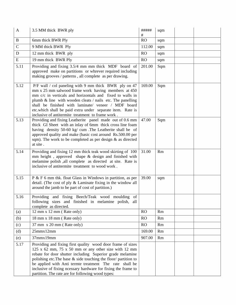
A 3.5 MM thick BWR ply #####
# sqm
B 6mm thick BWR Ply RO sqm
C 9 MM thick BWR Ply 112.00 sqm
D 12 mm thick BWR ply RO sqm
E 19 mm thick BWR Ply RO sqm
5.11 Providing and fixing 3.5/4 mm mm thick MDF board of
approved make on partitions or whrever required including
making grooves / patterns , all complete as per drawing.
201.00 Sqm
5.12 P/F wall / col paneling with 9 mm thick BWR ply on 47
mm x 25 mm salwood frame work having members at 450
mm c/c in verticals and horizontals and fixed to walls in
plumb & line with wooden cleats / nails etc. The panelling
shall be finished with laminate/ veneer / MDF board
etc.which shall be paid extra under separate item. Rate is
inclusive of antitermite treatment to frame work .
169.00 Sqm
5.13 Providing and fixing Leatherite panel made out of 0.6 mm
thick GI Sheet with an inlay of 6mm thick cross line foam
having density 50-60 kg/ cum .The Leatherite shall be of
approved quality and make (basic cost around Rs.500.00 per
sqm). The work to be completed as per design & as directed
at site .
47.00 Sqm
5.14 Providing and fixing 12 mm thick teak wood skirting of 100
mm height , approved shape & design and finished with
melamine polish ,all complete as directed at site. Rate is
inclusive of antitermite treatment to wood work .
31.00 Rm
5.15 P & F 6 mm thk. float Glass in Windows in partition, as per
detail. (The cost of ply & Laminate fixing in the window all
around the jamb to be part of cost of partition.)
39.00 sqm
5.16 Providing and fixing Beech/Teak wood moulding of
following sizes and finished in melamine polish, all
complete as directed.
(a) 12 mm x 12 mm ( Rate only) RO Rm
(b) 18 mm x 18 mm ( Rate only) RO Rm
(c) 37 mm x 20 mm ( Rate only) RO Rm
(d) 25mmx12mm 169.00 Rm
(e) 37mmx19mm 907.00 Rm
5.17 Providing and fixing first quality wood door frame of sizes
125 x 62 mm, 75 x 50 mm or any other size with 12 mm
rebate for door shutter including Superior grade melamine
polishing etc.The base & side touching the floor/ partition to
be applied with Anti termte treatment The rate shall be
inclusive of fixing ncessary hardware for fixing the frame to
partition. The rate are for following wood types:

a) Using Beech Wood 0.85 cum
b) UsingTeak wood 0.10 cum
5.18 Providing and fixing 40 mm thick wood glazed door shutter
having 150 wide styles, top rail & 200 mm wide bottom rail
and glazed with 6 mm thick clear float glass panel fixed
with 18 x 18 mm wood beading in the following wood:
a) Using C.P. Teak wood 6.00 Sq m
b) Using Beech wood 80.00 Sq m
Rate is inclusive of melamine spray polish & hardware as
detailed below.
1.Pair of Ozone make Mortice handle set (Model no OMH-
11 N)
2. ISI marked door closers Ozone make - OMC-22-K2K-N-
60, Make- Ozone
3. Ozone make mortice lock
4. Ozone make heavy Class 100 mm long BEARING SS
hinges - 3 nos.
Hardware Fittings
( The deduction for not fixing any hardware item shall also
be made on these rates .)
5.19 Providing and fixing sound proof door using 9mm ply both
side over frame of teak wood and filling insulation material
as approved, finished with 1mm thk. Laminate/4 mm thk.
Veneer over 9mm thk. Ply, including teak wood margin on
all exposed faces with polish & required hardware same as in
above item (cost of laminate/veneer/polish to be paid
seperately).
12.00 sqm
5.20 Providing and fixing 35 mm thick solid core non decorative
flush doors of approved make including fixing Beech/teak
wood lipping of 10 mm thickness on the perimeter of flush
door.The shutter shall be fixed using 3 numbers of 125 mm
heavy duty brass oxidised /crome finish hinges with S.S. pin.
The shutter shall be finished with laminate / veneer which
shall be paid extra under separate item . The lipping shall
be fixed after finishing of door shutter with laminate /
veneer etc. Rate shall be inclusive of melamine spray
polish on lipping , nails & adhesive etc.
2.00 Sqm
The door shall have the following hardwares which are
inclusive of rate .
1.Pair of ozone make mortice handles
2. ISI marked door closers ozone make
3. Ozone make mortice lock
4. Ozone make heavy Class 100 mm long BEARING SS

hinges - 3 nos.
5.21 Supply and fixing floor springs , DORMA make RO Each
5.22 Providing and fixing Ozone make mortice Handle Set
(Model no OMH-11 N) 2.00 Each
5.23 Providing and fixing Mortise Locks Model - OMC-22-K2K-
N-60, Make- Ozone 2.00 Each
5.24 Providing and fixing ISI marked Door closures Model- NSK
680 Ozone make. 2.00 Each
5.24A Providing and fixing ISI marked Door closures Model - CDC
3900 LEFT / RIGHT (AS PER DOOR OPENING) Ozone
make.
2.00 Each
5.25 Providing and fixing S.S. -304 finished Dorset make Tower
bolts of 200 mm long with matching screws 2.00 Each
5.26 Providing and fixing SS Hinges model no. OZ-SSBH 4x3x3
make - Ozone including stainless steel screws comlete. 10.00 Each
TOTAL OF WOOD WORK
6. STORAGES AND FURNITURES
6.1 Full height storage Unit: Providing and fixing appx. 2400mm
high storage unit made out of 19 mm BWR ply for verticals,
top, bottom and intermediate vertical partitions @ 900 c/c
or part thereof and backing of 6mm th. BWR ply . The top &
exposed sides of storgae to be finished with laminate and
complete in all respects as per design.
Shutters shall be in 19 mm BWP grade Block board with
teak wood lipping all-round. The front & back to be finished
with 1 mm thk laminate.
Shelves: Shelves are made of 19 mm BWR grade plywood
with teak wood lipping and fixed @ 375 mm c/c supported
on heavy duty S.S pins. The teak wood lipping shall be
polished.
Locks shall be Godrej make Universal drawer/cupboard lock
(model No 5041) dead lock with S.S key-master key for
groups as required.
Handles shall be Kich make AISI 316 grade 96 mm long 12
mm dia for each shutter.
Skirting: 100 x 19 mm ply for skirting. All external / visible
surfaces including top/ back if exposed, shall be finished
with 1.0 mm laminate of approved make & shade .

All internal surface of almirah including top of shelves ,
sides etc. shall be laminated with 1.0 mm thick laminate
of white shade . The bottom of shelves to be painted with
flat paint of approved shade. The top of storage unit also to
be finished with a mm thk lamianate.
The depth of storage to be as under:
a) 450 mm deep 10.00 Sq m
b) 600 mm deep 52.00 Sq m
c) 750 mm deep 32.00 Sq m
c) 945 mm deep 3.00 Sq m
6.2 Low height storage Unit: 450 mm deep, Similar to the above
item but with height ranging from 750-1200 mm .The top &
exposed sides of storgae to be finished with laminate and
complete in all respects as per design.
8.00 Sq m
6.03 Providing and fixing storage unit 600 mmm deep and
approx. 800 mm high under the counter for kitchen
Caracass shall be made out of 19 mm Marine Ply for
verticals, bottom and top and intermediate horizontal and
backing of 6mm marine Ply as per design.
One shelf made of 19 mm ply supported on Heavy duty pins.
Shutters shall be from 19 mm Th. BWP block board with
teak wood lipping, fixed with copper oxidized 75 mm long
hinges.
Hardware: Brass brush steel finish 50 mm long tower bolt for
one shutter and SS 96 mm long 8 mm dia CHC 104 C Kich
make combination finished C type Bow handles @ one for
each shutter. Locks shall be Godrej make cupboard lock with
S.S key with master keys for groups.
All the exposed/ visible surfaces shall be provided with 1.0
mm thick approved laminate . 7.00 Sq m
All the Internal surfaces shall also be finished with 1 mm
thick white laminate .
TOTAL OF STORAGES
7 PAINTING
7.1 Providing and applying on all exposed surfaces of walls,
columns, beams, ceiling etc 2 or more coats Plastic
Emulsion paint of approved make and shade over a coat of
primer and putty, etc, complete.
50 Sq m

7.2 Painting with minimum 2 coats of Lustre paint of approved
shade and make on the walls, plywood, Gyp board including
all necessary surface preparation ,application of putty and
primer etc. complete.
33.00 Sq M
7.3 Providing and applying Texture paint of approved make as
per design and pattern all complete as per manufacturer’s
specifications
66.00 Sq m
7.4 Providing and applying DUCO paint of approved make
shade all complete as per manufacturer’s specifications 35.00 Sq m
7.5 Providing and applying DUETTE (ICI or eq.) paint of
approved make , design and pattern all complete as per
manufacturer’s specifications
66.00 Sq m
7.6 Providing and applying on all exposed surfaces of flush
door/Ply ceiling 2 or more coats of flat paint of approved
make and shade over a coat of primer and putty including
surface preparation etc. complete.
5.00 Sq m
7.7 Providing and applying synthetic enamel paint whrever
required in 2 or more coats over a coat of primer etc.
complete. Rates are inclusive of surafce preparation.
10.00 Sq m
7.7A Providing and applying on all exposed surfaces of walls,
columns, beams, ceiling etc 2 or more coats of O.B.D. of
approved make and shade over a coat of primer and putty
including surface preparation etc. complete.
30 Sq m
7.8 Providing & applying Premiun quality melamine spray
polish using superior quality material (only approved sample
/ material to be used) over door / window frames including
moulding / door shutters / wall paneling etc. as per std. steps
complete in all respect desired shade as directed at site. (
measurement to be done for length / area)
7.8A Area of glazed door shutter, only area of one side to be
measured. 17.47 sqm
7.8B on door / window frames including mouldings attach to
frame 20.58 sqm
7.8C Moulding 37x19mm 164.98 Rm
TOTAL OF PAINTING
8 MISCELLANEOUS
8.01 Providing and fixing Roller blinds of " Mac" or "Vista" or
"Hunter Douglas" make (Basic price of Product 1800/- after
discount) of approved shade all complete as per
manufacturers specifications.
84.00 Sqm

8.02 P/F Garware film on glazing in door , partitions etc., all
complete as per manufacturers specifications . 174.00 Sqm
8.02A P/F 3M designer film (Base rate of film 225/-) on glazing in
door , partitions / wall etc., all complete as per manufacturers
specifications .
10.00 Sqm
8.03 P/doing Steel work in MS angles, flats, sq bars as per
drawing , design & directions including painting with two
or more coat of synthetic enamel paint over a cost of
primer .
RO Kg
8.04 P/F of frame less 12 mm thick toughened glass edge polished
fixed in partition as per drawing & design. Rate shall be
inclusive of aluminium floor u channels , fittings ,joint
filling with silicon sealant etc. complete as directed.
39.00 Sqm
8.05 P/F of fully glazed door shutter of 12mm toughened edge
polished glass single/double leaf including patch fitting, 450
mm long S.S Handle set,door locks and floor spring as
approved. Rate is inclusive of all hardware fittings such as
etc. complete as directed at site.
8.00 Sqm
8.06 P/Fixing 10 mm thk Laminated wooden Flooring (AC4 class)
& skirting of approved make & shade complete in all respect
.The flooring to be laid over PU foam over existing floor.The
wooden laminated flooring panels to be 12 -15 mm thk
tongue & groove joint
32.00 Sqm
8.07 P/Fixing 500 x500 mm carpet tiles of approved shade &
make with following specifications:
The tile to be made of multi level loop of 100% PP with
1/16" gauge with 21 OZ/Sqyard pile wt. with 4 mm average
ple height with PVC fibreglass backing for a heavy
commercial classification.
47.00 Sqm
8.08 P/F wall paper of approved make , shade & quality as
directed (base price Rs 1000/- per sqm) 34.00 Sqm
8.09 P/F 3D Board ( GLO 8011 or as approved ) over existing
partition ply including advesive etc. complete as per drawing
/ design.
35.00 Sqm
8.10 P/F 6mm Lacquer glass Sant gobin make ( base price of glass
300/- after discount) over existing partition ply including
advesive etc. complete as per drawing / design.
14.00 Sqm
8.11 P & Fixing dining Counter 2500x600x900 supported on 3
nos. 75 dia S.S. 304 grade pipes with 150 dia connecting
pracket in pantry finished with 19 mm thk Zed Black granite
on 19mm BWR Ply (cost of granite to be paid extra) fixed
with Araldite as per design/drawing.
1.00 each

8.12 P/F 600 wide Cash counter made of 19 mm thk commercial
board finished with 1 mm thk laminate with facia finshed
with 38 x19 mm thk. Beech/teak wood half round moulding
includive of a 750x450 laminate top key board with
telescopic channels including hardware & melamine polish
complete as per drawing.
1.00 RM
8.13 P/F Reception Table with 19 mm thk commercial board
finished with 12 MM thick Du pont or equivalent
acrylic material and laminate with complete hardware ,
accessories & finishes as per design/drawing.
1.00 each
8.14 P/F Commercial Board U shape box 100x100x100 mm
finished with 4 mm thk. Veneer ( Rs. 35/- Sft) Superior grade
melamined polished & fixed to partition & ceiling as per
design & directions.
10.00 RM
8.15 P/F 4 mm thk back painted glass in existing panelling as per
directions 50.00 Sqm
8.16 P/F 6 mm thk back painted glass in existing panelling as per
directions 5.00 Sqm
8.17 P/F white board as per directions 5.00 Sqm
TOTAL OF MISCELLANEOUS WORKS
9 FIRE FIGHTING WORK
9.1 Disconnecting/reconnecting & carrying out the job
mentioned below including testing & commissioning to the
company/premises owners satisfaction as per existing site
conditions.
1.00 LS
9.2 Providing, fixing and jointing including testing heavy quality
Mild Steel pipes conforming to IS:1239/partI/1974 including
cutting, threaded or welded (all type) joints as per detialed
specifications.and providing suitable flanges wherever
required,complete with necessary fittings viz bends, tees,
reducers etc.required including fixing the pipes on
wall/ceilling/ beam/floor with suitable hangers, clamps and
painting the pipe of following sizes complete. Pipes should
be welded joint(all type of welded joints)
A 50 mm dia 42 RM
b. 25 mm dia 56 RM

9.3 Providing and fixing 15mm gunmetal sprinkler head with
quartzoid bulb and set to operate at specified temperature
pendent/upright/side wall as per the location indicated on the
drawings. Sprinklers 68degree C FOC/UL/FM approved
complete with socket nipple, adaptor etc. sprinkler shall be
pendant type. Temperature of operation 68 deg. C Make:
Tyco
a. Up right type 35.00 No
9.4 Providing and fixing of SS sprinkler connector pipe (1000
mm long ) 54.00
No
TOTAL OF FIRE FIGHTING WORK
ESTIMATE CIVIL & INTERIOR WORKS.
Unit
rate Total
Amount
S.NO. DESCRIPTION UNIT Qty
1 Wooden doors with glass as
19 doors
per drawings. 2100*840 mm
2 Wooden doors with glass as
8 doors
per drawings.2100*1100 mm
3 Windows glass 8mm Sqft 480 sqft
4 Ceiling sqft 9000 sqft
5 Granite flooring Sqft 850 sqft
6 Wooden flooring Sqft 350 sqft
7 Carpet tile flooring Sqft 450 sqft
8 Tile scatting Rft
9 Laminate on existing panelling Sqft 1800 sqft
10 Laminated panelling Sqft 1100 sqft
11 Plastic emulsion paint Sqft 4000 sqft
12 Polish in conf. room Sqft 700 sqft
13 All windows and doors polish
14 Floor polishing Sqft 2500 sqft
15 Reception table 1 no'S
16 PANTRY:
A Wall punning Sqft 350 sqft
B Granite counter/cabinet
C Plumbing work
D Wall tiles
17 TOILETS:
A W.C Hindware
8 no's
B Urinal Hindware
4 no's
C Wash basin Hindware
8 no's

D Wall tiles 300*600 mm Sqft 1400 sqft
E Floor tiles 450*450 Sqft 650 sqft
F Removing of existing tiles
18 Removing of debris from site
TOTAL

Section C – Electrical and Fire Alarm System
S.NO. DESCRIPTION QTY. UNIT
Unit
rate Total
Amount
The rates quoted under this sub head shall include the following:
a) Providing proper tools and plants for doing proper cabling job.
b) Cutting chases, providing clamps hangers etc. for fixing the
cable/cable tray earth strip / earth wire in position.
c) Excavation back filling and disposal of surplus earth as required.
d) The cables in proper way taking into consideration the turning
radius of cable.
S.NO. DESCRIPTION QTY UNIT 1) Supply, Installation, Testing & Commissioning of Advance
Miantenance Free Chemical Gel Earthing System of 10 feet
length, 2 inch dia, 2 mm thick electrolytic grade copper tube duly
filled with conducting chemicals with the permenant sealings at
the both the ends with the lead terminal at the top along with 5
Kgs of Part A GRIP & 5 Kgs of Part B GRIP combined to form a
chemical gel to retain the life span of 30 years with the heavy
duty poly plastic earth pit cover.
Sets
Rate only presently buidling earth will be used.
2) Supply, installation, effecting proper connection testing and
commissioning of the following size copper earth strips / G.I.
Wires as required.
a) 25 x 3 mm G.I. Strip RM
b) 25 x 3 mm Cu Strip 0 RM
c) 8 SWG G.I. Wire RM
d) 35sqmm copper flexible RM
3) Supply, laying, installing, testing & commissioning in position of
the following size XLPE aluminium conductor armoured cables
as per IS: 1554. On cable tray in massonary trench / directly
burried in ground. The quoted price shall be inclusive of
clamping while laying on tray cost of sand cushioning and brick
protection while directly burrying in ground and sadding in case
of laying in massoinary trench.
a) 4 X 95 sq mm Al Arm RM
b) 4 x 16 sq. mm cable RM
c) 4 x 10 sq. mm cable 0 RM
d) 4 x 6 sq. mm cable copper Arm RM
e 2 x 6 sq. mm cable (Inverter) RM

4) Supplying, installing, effecting connection testing and
commissioning cable and joints with solderless crimping lugs,
double compression glands etc. as required with earthing of cable
glands.
a) 4 X 95 sq mm Al Arm 4 Sets b) 4 x 16 sq. mm cable
4 Sets
c) 4 x 10 sq. mm cable
Sets
d) 4 x 6 sq. mm cable 6 Sets
e 2 x 6 sq. mm cable 6 Sets
TOTAL SUB HEAD "A"
SUB HEAD "B" DISTRIBUTION BOARD AND INVERTER
S.NO. DESCRIPTION QTY UNIT
Unit Rate Total
Amount A. DISTRIBUTION BOARDS Design, manufacture, supplying, installing testing and
commissioning of distribution boards manufactured
out of 18 S.W.G. C.R.C.A. sheet double door type duly
painted, complete with copper bus bars, neutral link,
earth strip, cable alley etc. as required.
1. 8 WAY T.P.N. (FOR LIGHTING) MCB FP 63A 3 Sets MCB 4P 40A 3 sets MCB SP 0.32A 144 sets BLANK 24 sets 2. 12 WAY T.P.N. VERTICAL AS MAIN PANEL 12 WAY TPN FOR UPS OUTPUT PANEL 2 Sets 6. 12 WAY S.P.N. (FOR INVERTER) 12 Nos. S.P.M.C.B.S. as outgoing and 40 Amps. DP
M.C.B. with as incomer. 1 Sets
TOTAL SUB HEAD "B"
SUB - HEAD "C" POINT WIRING
POINT WIRING: The rates for Point Wiring shall include the following:
a) Point Wiring shall include with circuit wiring (2.5 sq. mm.) of light / fan / outlets of any length
from the distribution board via switch to the point.

b) All the light fixtures, ceiling fans, exhaust fans, third pin of outlets, switch and outlet boxes
shall be earthed with 1 mm dia. Insulated copper wire.
c) Providing & Embedding conduits and allied fittings in walls / floors etc. cutting chases and
making the surfaces good or fixing in partition cutting chases paneling false ceiling work with
proper hangers / clamps. (Conduits & wiring for power out-lets only shall be paid seperately on
linear measurements basis).
d) All accessories necessary to complete the wiring as specified.
e) Most of conduiting shall be done on surface, boxes may be urea type in place of G.I.
S.NO. DESCRIPTION QTY UNIT
Unit rate Total
Amount 1 (i) Wiring for the following light points
with 1.5 sq.mm. PVC insulated copper
conductor FRLS wires in proposed
concealed / exposed PVC Conduit called
for the specification including providing 6
amp modular type switches cover plate to
switch boxes and earthing.
a) One point controlled by one 6 Amp switch 300 Nos. Switch 5A 120 Nos.
Blank plate for 3M speaker boxes. 40 Nos. 2 (i) Wiring for 6 Amp primary light plug
outlets with 1.5 sq.mm. PVC insulted
copper conductor FRLS wires in proposed
concealed / exposed M.S. conduits as
called for including providing 6 Amp 3 pin
socket outlet and 6 Amp switche sockets,
cover plate to outlet boxes and earthing etc
as rquired. 60 Nos.
(ii) Wiring for 6 Amp secondary light plug
outlets with 1.5 sq.mm. PVC insulted
copper conductor FRLS wires in proposed
concealed / exposed M.S. conduits as
called for including providing 6 Amp 3 pin
socket outlet and 6 Amp switche sockets,
cover plate to outlet boxes and earthing etc
as rquired. 90 Nos.
3) Wiring for exhaust fan / ceiling fan /
Bracket fan points with 1.5 sq.mm. PVC
insulated copper conductor wires in
concealed/ exposed M.S. conduits as
called for including providing 6 Amp 3 pin
socket near exhaust fan G.I. box for
housing switches 6 Amp socket outlet and
cover plate to switch and outlet boxes and
earthing etc as required. 5 Nos.

4) Wiring for following light points directly
controlled by DB's with 2.5 sq.mm FRLS
copper conductor wires in
concealed/exposed M.S. conduits as called
for including terminating wires in DB as
well as fixtures.
a) One point controlled by MCB in DB (cost
of MCB included in the cost of D.B) 0 Nos.
b) Extra for every additional point in the same
set. 0 Nos.
5. Supplying, Laying and Fixing of 15/5 Amp
power plug primary outlets with 2 X 4 +
2.5 sq.mm. PVC insulated copper
conductor wires in concealed / exposed GI
conduits as called for including providing
15 Amp 6 pin socket outlet and 15 Amp
switch, cover plate to outlet boxes and
earthing etc as required. 6 Nos.
6. Supplying, Laying and Fixing of 15/5 Amp
power plug secondry outlets with 2 X 2.5
+ 1.5 sq.mm. PVC insulated copper
conductor wires in concealed/exposed GI
conduits as called for including providing
15 Amp 6 pin socket outlet and 15 Amp
switch, cover plate to outlet boxes and
earthing etc as required. 0 Nos.
7. Supplying, Laying and Fixing of 20 AMP
SP Industrial Socket controlled by 20 Amp
SP MCB with 2 X 6 + 2.5 sq.mm. PVC
insulated copper conductor wires in
concealed / exposed PVC. conduits as
called including providing of MS enclosure
etc. as required. 2 Nos.
8. Supply and fixing of primary UPS points
with 3 X 2.5 sq.mm. copper wire in
exposed / concealed proposed PVC.
conduit comprising of 2 Nos. 5 Amps. 5
pin sockets controlled by 1 Nos. 5 Amps.
switch with indication lights complete
with cover plate, M.S. boxes etc. 60 Nos.
9. Supply and fixing of secondary UPS
points with 3 X 1.5 sq.mm. copper wire in
exposed / concealed proposed PVC conduit
comprising of 2 Nos. 5 Amps. 5 pin
sockets controlled by 1 Nos. 5 Amps.
switch with indication lights complete
with cover plate, M.S. boxes etc. 90 Nos.
10. Supply, Installation of following GI
conduits with junction boxes complete.
i) 20 mm dia conduit 0 RM

ii) 25 mm dia conduit 150 RM iii) 32 mm dia conduit 0 RM iv) 40 mm dia conduit 0 RM v) 20 mm dia. flexible conduit. 500 RM
11. Supply and drawing effecting of the
following FRLS wires in the existing
conduits.
i) 2 x 4 sq.mm. wire along with 1 No. 2.5
Sq.mm FRLS insulated copper wire. 2 Coil
ii) 2 x 6 sq.mm. wire along with 1 No. 2.5
Sq.mm FRLS insulated copper wire. 0 coil
iii) 2 x 10 sq.mm. wire along with 1 No. 4
Sq.mm FRLS insulated copper wire. 0 coil
iv) 2 x 2.5 sq.mm. wire along with 1 No. 2.5
Sq.mm FRLS copper wire. 6 Coil
v) 2 x 1.5 sq.mm. wire along with 1 No. 1.5
Sq.mm FRLS copper wire. 6 Coil
TOTAL SUB HEAD "C"
Note : Requirement of GI Pipes/ PVC conduits will discussed in the pre bid meeting specifically.
SUB - HEAD "D" LOW CURRENT SERVICES
a) The rates under this sub head shall include:
b) Embedding conduits and allied fittings in walls / floors etc. by cutting chases and making the
surface good or fixing in partition cutting chase paneling / false ceiling work with proper hangers /
clamps.
c) 2 mm dia GI pull wires in conduit work.
S.NO. DESCRIPTION QTY UNIT
Unit rate Total
Amount
Providing and fixing in position GI 65mm x 100mm x
50mm T.V. outlet boxes with cover plate and
T.V.socket. 2 set
Supply and laying of Co- axial cable RG - 6 in
existing conduit complete as required. 100 m
Supplying, fixing, testing & commissioning of
Computer data cable, Cat-6 including terminating
with numbering ferrules on both ends 6 Boxes
Supply and fixing 2 pair 0.6 mm dia copper
conductor (ATC) wires from junction box to outlet
complete with effecting connections with numbering
ferrules. 30 coil

(ii) Providing and fixing in position following GI/MS
conduits including providing all accessories concealed
or exposed as required including cast iron junction
boxes and approved cover plate complete with GI pull
wire.
a) 20 mm dia GI/MS conduit 0 RM b) 25 mm dia GI/MS. conduit 150 RM c) 32mm. dia GI/MS. conduit 40 RM d) Providing and fixing in position GI / 65 mm x 100
mm x 50 mm Computer outlet boxes with cover
plate & RJ-45 outlet 35 set
e) Providing and fixing in position GI / 65 mm x
100 mm x 50 mm Telephone outlet boxes with cover
plate & RJ-11 sockets. 120 set
5. Supply and fixing of 150 pair tag (krone type) blocks
duly housed in MS / wooden enclosure 1 No.
6. Supplying and fixing 10 pair 0.6mm. dia copper
conductor (ATC) wire. 50 RM
TOTAL SUB HEAD "D"
SUB - HEAD "E" SUPPLY & FIXING OF LIGHTING FIXTURES
The rates quoted under this sub head shall include the followings:-
a) Receiving, assembly, testing and commissioning of all fixtures issued free for fixing
b) Safe custody of fixtures during execution time shall be the responsibility of contractor and and
damages of caused shall be charged to contractor account.
c) Earthing of all fixtures with copper wire
d) Painting of all supports and down rods as required and called for
S.NO. DESCRIPTION QTY UNIT
Unit
Rate Total
Amount 1. Receiving fixing in position effecting proper connection
testing and commissioning of prewired fluorescent
fixtures of all sizes on ceiling or on walls with all fixing
accessories complete as required. 131 Each
2. Receiving and fixing in position effecting proper
connections testing and commissioning of
incandescent / CFL / halogen ceiling bracket / pendent
bulk heads lights as required. 235 Each
b) 2 x 36 watts CFL mirror optic luminaire with paralite P5
louvers surface mounted light fixture "Philips CAT
FBS450 2x36PLL D-6, DF 131 Nos.
c) 2x 18 watts CFL recessed mounted light fixture, "Philips
CAT FBH 150M 2xPL-C/4P18W EBW complete with
lamps, ballast etc. as required. 175 Nos.

d) 1 x 28 watts T5 decorative type light fixture, Wipro CAT
GCF 31128 SGW 1x28 w complete with lamps etc. as
required. 35 Nos.
e) 1 x 28 watts T5 decorative type light fixture, "PHILIPS
Cat No. TMS 122M 1xTL5-28w EBW complete with
lamps etc. as required. 27 Nos.
g) Supply of 300 mm. dia 900 R.P.M. exhaust fan with
louvered shutters. 5 Nos.
TOTAL SUB HEAD "E"
SUB HEAD "F" P.A. SYSTEM
S.No. DESCRIPTION
QTY UNIT Unit
Rate Total
Amount Supply, installing, testing and commissioning of
following P.A. System equipment.
1) SPEAKERS Ceiling mounted speakers with 8 ohm impedence and 5
watt rated output, in metal casing with line matching
transformers with tappings of 5W, 3W & 1W. 0 Nos.
2) VOLUME CONTROL SWITCHES Rotary volume control switches heavy duty type for
above transformers with `ON' `OFF' facility. The volume
control switch can be either in stepless version or 7
stepped click free version housed in G.I. box. 0 Nos.
3) SPEAKER WIRING Speaker wiring in 20 mm dia M.S. conduits with twin
twisted 40/0.2 mm 2 core loudspeaker cable. 0 RM
4) Amplifier 200 watts P.M.P.O. with 2 inputs with speaker
matching 4,18,16 ohms. 70/100 volts. R.O. Nos.
TOTAL SUB HEAD "F"
SUB HEAD - "G" FIRE ALARM SYSTEM
S.NO DESCRIPTION
QTY UNIT Unit
rate Total
Amount FIRE DETECTION SYSTEM
Supply, installation, testing and commisioinng of
microprocessor based expandable Analogue addressable
type fire alram control panel with min 160 characters
display. The panel should be equipped of 1 loop
expandable to 2 loop with each loop capacity to take 99
addreessable detectors/ devices in one loop, 1000 event
history, four acess levels, system protocol, suffiecnt
numbers of programmable relays controls for controlling
AHU etc. 1 each

1 Supply, installation and commisioing of UL listed repeater
panel with minimum 160 charaters backlit LCD display &
with event and audiable status LED'S scroll button to view
additional events, local sounder and provided in its
encloser 1 Each
2 SITC of UL listed intelligent addressable photo electric
smoke detectors with base built in isolators for distributed
intelligence and electronic intelligence & electronic
addressing 63 Each
3 SITC of UL listed intelligent addressable heat detectors
with base built in isolators for distributed intelligence and
electronic intelligence & electronic addressing 38 Each
4 SITC of UL listed intelligent addressable manual call
points /pull station. 3 Each
5 Supply, installation, testing and commissioning of
Addressable hooters of intensity minimum 90db suitbale
for alram siren 3 Nos.
6 Supply, installation, testing and commissioning of
Addressable resposne indicators 43 No.
8 Supplying, installing, testing and commissioning 2 x 1.5
Sq.mm Copper conductor PVC insulated, PVC sheathed
armoured MICC cable including cable end termination. 1000 RMT.
Supply and installation of sprinkler system by extending it
with GI flexible pipe and new sprinkler 30 set
TOTAL SUB HEAD "G"
SUB HEAD - "H" OTHER ITEMS
SS covers for the junction boxes Qty Unit Unit
rate Total
Amount
350x300mm 4 each
450x200 mm each
550x350 mm each
Cable trey 200x40mm GI Perforated 50 meter
TOTAL SUB HEAD "H"
SUB HEAD “I” FIRE CLEARANCE CERTIFICATE
DESCRIPTION CHARGES/ FEE Fire Clearance Certificate from the Govt. Authority