Embed Size (px)
DESCRIPTION
Final Version Energy Harvesting using antennas
Citation preview
I. INTRODUCTION
Energy Harvesting, as the name implies, is the
process of harvesting energy from different energy
sources. Energy Harvesting may also be known as
Power harvesting or Energy scavenging. The
Different energy sources from which energy can be
derived are Conventional Sources, Renewable
sources such as Solar, Wind, Thermal, Tides etc. or
Manmade Energy sources such as RF Energy.
Deriving Energy from Non-Conventional Power
Sources has numerous challenges and depends upon
the environmental conditions. More over the energy
obtained from such Non Conventional Sources
requires more Space and the results are non
Linear[1].
II. NEED FOR ENERGY HARVESTING
A Survey conducted by WWRF predicted that by
2020, there will be 7 Trillion wireless devices in the
world serving 7 Billion People, which equates to
around 1000 wireless devices per individual. The
energy needed to power these devices will be quite
significant. Even now the energy needed to power
the available wireless devices around the world is
also considered significant. Because, a huge part of
the energy produced in the world, is used to power
these wireless electronic devices.[2] For example,
consider a Mobile communication network. For
seamless communication between mobile devices,
the base stations are to be powered 24X7
throughout the year. Even though the base station is
powered all through the year, the power from the
communication tower is not completely utilized.
Hence most of the energy is converted to futile heat
energy.
III. RADIO FREQUENCY AS A SOURCE OF ENERGY
Radio Frequency Energy(RF Energy) is ubiquitous
and found in large amounts in the environment.
Most of this energy is either absorbed by Living
things or Non Living Things around the world and
finally lost as Heat Energy. This Heat Energy also
contributes a very small extent to the Global
Warming. Hence this ambient RF Energy can be
tapped and utilized to power small wireless devices
and other electronic devices such as home & car
electronic devices, Bio-implanted devices, etc[3].
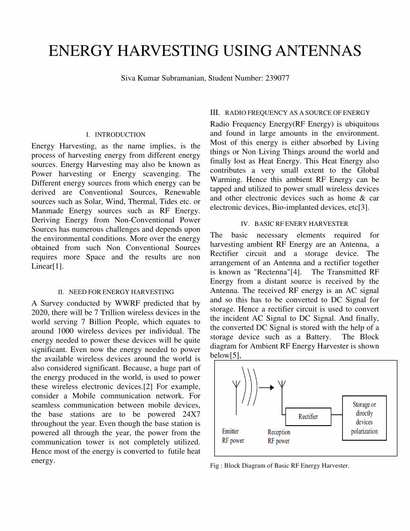
IV. BASIC RF ENERY HARVESTER
The basic necessary elements required for
harvesting ambient RF Energy are an Antenna, a
Rectifier circuit and a storage device. The
arrangement of an Antenna and a rectifier together
is known as "Rectenna"[4]. The Transmitted RF
Energy from a distant source is received by the
Antenna. The received RF energy is an AC signal
and so this has to be converted to DC Signal for
storage. Hence a rectifier circuit is used to convert
the incident AC Signal to DC Signal. And finally,
the converted DC Signal is stored with the help of a
storage device such as a Battery. The Block
diagram for Ambient RF Energy Harvester is shown
below[5],
Fig : Block Diagram of Basic RF Energy Harvester.
ENERGY HARVESTING USING ANTENNAS
Siva Kumar Subramanian, Student Number: 239077
V. DIFFICULTIES AND POSSIBLE SOLUTIONS IN RF
ENERGY HARVESTING
The power received from the EM waves is very low
and it is difficult to harness such low power energy
using regular diodes. Hence, Schottky diodes are
used in the rectifying circuit to harness such low
power energy. The Schottky diodes used are of
highest speed with lowest voltage drop and low
power loss due to conduction and switching. Hence
it increases the efficiency of the circuit.
The input signal voltage reaching at the rectifier
circuit is less than the threshold voltage of the
diodes used and hence it affects the energy
harvester's efficiency. Hence to overcome this
problem, either the threshold voltage of the diodes
has to be decreased or the input voltage has to be
boosted.
To decrease the threshold voltage of the diodes,
special type of Schottky diodes such as GaAs
Schottky Diodes or specially fabricated discrete Si
Schottky Diodes are used. By using these diodes
low forward threshold voltage of 200mV is
obtained and 20% efficiency is utilized for a input
power of -20dBm. In decreasing the threshold
voltage, voltage biasing of the diodes are to be
taken care off. Voltage Biasing of the Diodes is
necessary for turning on the Diodes and for this
different circuits are designed and used. They are 1.
Distributor Circuits, which has higher charging
current for low input power, 2. Floating gate
devices, 3. Off-chip high impedance resistor
networks.
To Boost the input signal voltage received from the
antenna, different matching networks and various
voltage doubler circuits are used. Few voltage
doubler circuits used to boost the input voltage are
1. Single stage Voltage doubler, 2. Cascaded
Voltage doubler with boosting circuit, 3. Antenna
Coupled Cascaded Voltage doubler with Boosting
Circuit. The fundamental idea behind the voltage
doubler circuit is that by using LC Resonant circuit
large voltages are produced even when the input
voltage is very low. Such a voltage doubler circuit
is used across the MOSFET thereby turning on the
device easily and producing large voltages across it.
Another way of boosting the input signal voltage is
by using high quality capacitor at low input power
level . The Capacitor is placed parallel to MOSFET
and hence at resonance, this capacitor delivers large
voltage and biasing the MOSFET and thereby
increases the harvesting current.
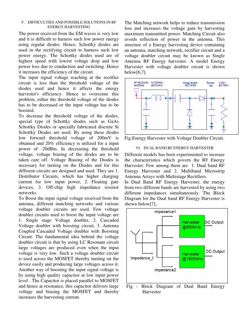
The Matching network helps to reduce transmission
loss and increases the voltage gain by harvesting
maximum transmitted power. Matching Circuit also
avoids reflection of power in the antenna. This
structure of a Energy harvesting device containing
an antenna, matching network, rectifier circuit and a
voltage doubler circuit may be known as Single
Antenna RF Energy harvester. A model Energy
Harvester with voltage doubler circuit is shown
below[6,7].
Fig:Energy Harvester with Voltage Doubler Circuit.
VI. DUAL BAND RF ENERGY HARVESTER
Different models has been experimented to increase
the characteristics which govern the RF Energy
Harvester. Few among them are 1. Dual band RF
Energy Harvester and 2. Multiband Microstrip
Antenna Arrays with Multistage Rectifiers.
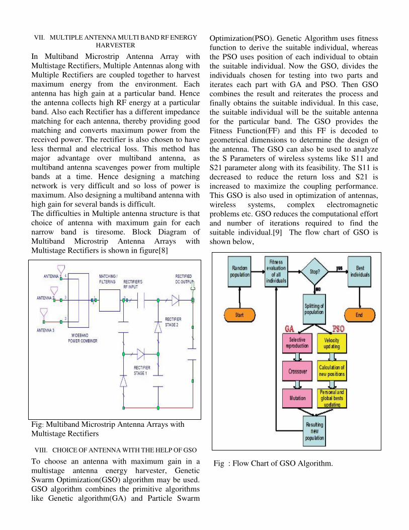
In Dual Band RF Energy Harvester, the energy
from two different bands are harvested by using two
different impedances simultaneously. The Block
Diagram for the Dual band RF Energy Harvester is
shown below[7],
Fig : Block Diagram of Dual Band Energy
Harvester
VII. MULTIPLE ANTENNA MULTI BAND RF ENERGY
HARVESTER
In Multiband Microstrip Antenna Array with
Multistage Rectifiers, Multiple Antennas along with
Multiple Rectifiers are coupled together to harvest
maximum energy from the environment. Each
antenna has high gain at a particular band. Hence
the antenna collects high RF energy at a particular
band. Also each Rectifier has a different impedance
matching for each antenna, thereby providing good
matching and converts maximum power from the
received power. The rectifier is also chosen to have
less thermal and electrical loss. This method has
major advantage over multiband antenna, as
multiband antenna scavenges power from multiple
bands at a time. Hence designing a matching
network is very difficult and so loss of power is
maximum. Also designing a multiband antenna with
high gain for several bands is difficult.
The difficulties in Multiple antenna structure is that
choice of antenna with maximum gain for each
narrow band is tiresome. Block Diagram of
Multiband Microstrip Antenna Arrays with
Multistage Rectifiers is shown in figure[8]
Fig: Multiband Microstrip Antenna Arrays with
Multistage Rectifiers
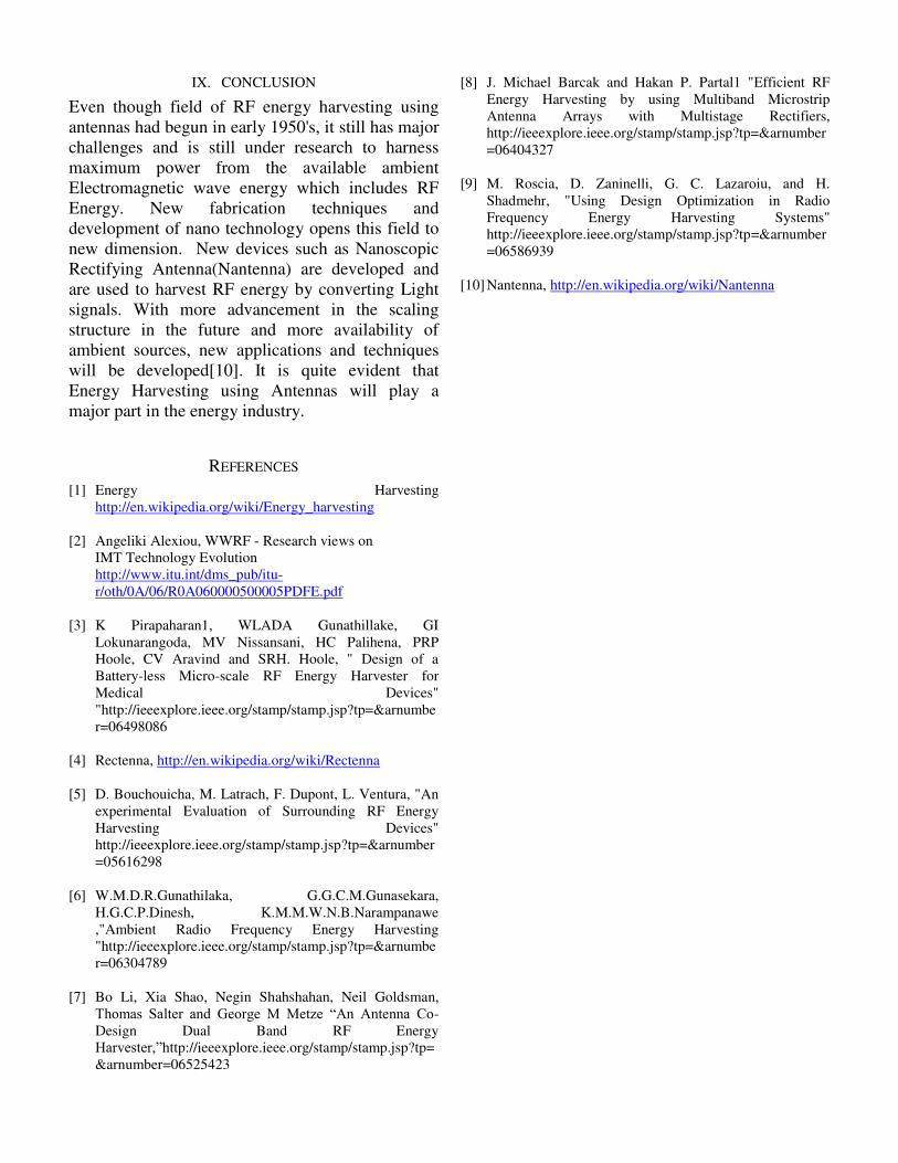
VIII. CHOICE OF ANTENNA WITH THE HELP OF GSO
To choose an antenna with maximum gain in a
multistage antenna energy harvester, Genetic
Swarm Optimization(GSO) algorithm may be used.
GSO algorithm combines the primitive algorithms
like Genetic algorithm(GA) and Particle Swarm
Optimization(PSO). Genetic Algorithm uses fitness
function to derive the suitable individual, whereas
the PSO uses position of each individual to obtain
the suitable individual. Now the GSO, divides the
individuals chosen for testing into two parts and
iterates each part with GA and PSO. Then GSO
combines the result and reiterates the process and
finally obtains the suitable individual. In this case,
the suitable individual will be the suitable antenna
for the particular band. The GSO provides the
Fitness Function(FF) and this FF is decoded to
geometrical dimensions to determine the design of
the antenna. The GSO can also be used to analyze
the S Parameters of wireless systems like S11 and
S21 parameter along with its feasibility. The S11 is
decreased to reduce the return loss and S21 is
increased to maximize the coupling performance.
This GSO is also used in optimization of antennas,
wireless systems, complex electromagnetic
problems etc. GSO reduces the computational effort
and number of iterations required to find the
suitable individual.[9] The flow chart of GSO is
shown below,
Fig : Flow Chart of GSO Algorithm.
IX. CONCLUSION
Even though field of RF energy harvesting using
antennas had begun in early 1950's, it still has major
challenges and is still under research to harness
maximum power from the available ambient
Electromagnetic wave energy which includes RF
Energy. New fabrication techniques and
development of nano technology opens this field to
new dimension. New devices such as Nanoscopic
Rectifying Antenna(Nantenna) are developed and
are used to harvest RF energy by converting Light
signals. With more advancement in the scaling
structure in the future and more availability of
ambient sources, new applications and techniques
will be developed[10]. It is quite evident that
Energy Harvesting using Antennas will play a
major part in the energy industry.
REFERENCES
[1] Energy Harvesting
http://en.wikipedia.org/wiki/Energy_harvesting
[2] Angeliki Alexiou, WWRF - Research views on
IMT Technology Evolution
http://www.itu.int/dms_pub/itu-
r/oth/0A/06/R0A060000500005PDFE.pdf
[3] K Pirapaharan1, WLADA Gunathillake, GI
Lokunarangoda, MV Nissansani, HC Palihena, PRP
Hoole, CV Aravind and SRH. Hoole, " Design of a
Battery-less Micro-scale RF Energy Harvester for
Medical Devices"
"http://ieeexplore.ieee.org/stamp/stamp.jsp?tp=&arnumbe
r=06498086
[4] Rectenna, http://en.wikipedia.org/wiki/Rectenna
[5] D. Bouchouicha, M. Latrach, F. Dupont, L. Ventura, "An
experimental Evaluation of Surrounding RF Energy
Harvesting Devices"
http://ieeexplore.ieee.org/stamp/stamp.jsp?tp=&arnumber
=05616298
[6] W.M.D.R.Gunathilaka, G.G.C.M.Gunasekara,
H.G.C.P.Dinesh, K.M.M.W.N.B.Narampanawe
,"Ambient Radio Frequency Energy Harvesting
"http://ieeexplore.ieee.org/stamp/stamp.jsp?tp=&arnumbe
r=06304789
[7] Bo Li, Xia Shao, Negin Shahshahan, Neil Goldsman,
Thomas Salter and George M Metze “An Antenna Co-
Design Dual Band RF Energy
Harvester,”http://ieeexplore.ieee.org/stamp/stamp.jsp?tp=
&arnumber=06525423
[8] J. Michael Barcak and Hakan P. Partal1 "Efficient RF
Energy Harvesting by using Multiband Microstrip
Antenna Arrays with Multistage Rectifiers,
http://ieeexplore.ieee.org/stamp/stamp.jsp?tp=&arnumber
=06404327
[9] M. Roscia, D. Zaninelli, G. C. Lazaroiu, and H.
Shadmehr, "Using Design Optimization in Radio
Frequency Energy Harvesting Systems"
http://ieeexplore.ieee.org/stamp/stamp.jsp?tp=&arnumber
=06586939
[10] Nantenna, http://en.wikipedia.org/wiki/Nantenna