Embed Size (px)
Citation preview
Final report RL 2017:08e Serious incident at Malmö Airport on 29 September 2016 involving SE-DSP of the model AVRO 146-RJ100, operated by Braathens Regional Aviation AB. File no. L-101/16
2017-09-11

RL 2017:08e
Postadress/Postal address Besöksadress/Visitors Telefon/Phone Fax/Facsimile E-post/E-mail Internet P.O. Box 6014 Sveavägen 151 +46 8 508 862 00 +46 8 508 862 90 [email protected] www.havkom.se SE-102 31 Stockholm Stockholm Sweden
SHK investigates accidents and incidents from a safety perspective. Its investigations are aimed at preventing a similar event from occurring in the future, or limiting the effects of such an event. The investigations do not deal with issues of guilt, blame or liability for damages.
The report is also available on SHK’s web site: www.havkom.se
ISSN 1400-5719
This document is a translation of the original Swedish report. In case of discrepancies between this translation and the Swedish original text, the Swedish text shall prevail in the interpretation of the report.
Photos and graphics in this report are protected by copyright. Unless other-wise noted, SHK is the owner of the intellectual property rights.
With the exception of the SHK logo, and photos and graphics to which a third party holds copyright, this publication is licensed under a Creative Commons Attribution 2.5 Sweden license. This means that it is allowed to copy, distribute and adapt this publication provided that you attribute the work.
The SHK preference is that you attribute this publication using the follow-ing wording: “Source: Swedish Accident Investigation Authority”.
Where it is noted in the report that a third party holds copyright to photos, graphics or other material, that party’s consent is needed for reuse of the material.
Cover photo no. 3 - © Anders Sjödén/Swedish Armed Forces.

RL 2017:08e
Content
General observations ...................................................................................................... 5
The investigation ............................................................................................................ 5
SUMMARY ....................................................................................................... 8
1. FACTUAL INFORMATION .......................................................................... 10
1.1 History of the flight .......................................................................................... 10 1.1.1 Preconditions ....................................................................................... 10 1.1.2 The event ............................................................................................. 10
1.2 Injuries to persons ............................................................................................ 11 1.3 Damage to aircraft............................................................................................ 12 1.4 Other damage ................................................................................................... 12
1.4.1 Environmental impact.......................................................................... 12 1.5 Personnel information ...................................................................................... 12
1.5.1 Qualifications and duty time of the pilots ........................................... 12 1.5.2 Other personnel ................................................................................... 13
1.6 Aircraft information ......................................................................................... 13 1.6.1 Airplane ............................................................................................... 13 1.6.2 Description of parts or systems related to the occurrence ................... 14 1.6.3 Stall Identification Fault ...................................................................... 15 1.6.4 Replacement of damaged airflow sensor ............................................. 18 1.6.5 Aircrafts Maintenance Manual, AMM ................................................ 19 1.6.6 Abnormal procedures check list ......................................................... 20
1.7 Meteorological information ............................................................................. 21 1.8 Aids to navigation ............................................................................................ 21 1.9 Communications .............................................................................................. 21 1.10 Aerodrome information ................................................................................... 21 1.11 Flight recorders ................................................................................................ 21
1.11.1 Flight Recorders (FDR, QAR) ............................................................. 21 1.11.2 Cockpit Voice Recorder (CVR) .......................................................... 22
1.12 Site of occurrence ............................................................................................ 22 1.12.1 Aircraft after the incident .................................................................... 22
1.13 Medical and pathological information ............................................................. 22 1.14 Fire ................................................................................................................... 22 1.15 Survival aspects ............................................................................................... 22
1.15.1 Rescue operation ................................................................................. 22 1.16 Tests and research ............................................................................................ 22
1.16.1 Examination of the airflow sensor ....................................................... 22 1.16.2 Analysis of repair history of sensor model .......................................... 24 1.16.3 Routines at Safe Flight ........................................................................ 24 1.16.4 BAE Systems prediction of angle of attack ......................................... 24 1.16.5 Test of the Stall identification and warning system ............................. 25
1.17 Organisational and management information .................................................. 26 1.18 Additional information..................................................................................... 26
1.18.1 Operators maintenance procedures ...................................................... 26 1.18.2 History of Airflow sensor S/N 211 ...................................................... 27 1.18.3 Actions taken ....................................................................................... 27
1.19 Special methods of investigations .................................................................... 27
2. ANALYSIS ...................................................................................................... 28
2.1 The flight .......................................................................................................... 28

RL 2017:08e
4 (31)
2.2 Technical ......................................................................................................... 28 2.2.1 Replacement airflow sensor ................................................................ 28 2.2.2 Logic of the stall warning and identification system .......................... 28 2.2.3 History of the faulty airflow sensor ..................................................... 29
3. CONCLUSIONS ............................................................................................. 30
3.1 Findings ........................................................................................................... 30 3.2 Causes/Contributing Factors ........................................................................... 30
4. SAFETY RECOMMENDATIONS ................................................................ 31

RL 2017:08e
5 (31)
General observations The Swedish Accident Investigation Authority (Statens haverikommission – SHK) is a state authority with the task of investigating accidents and incidents with the aim of improving safety. SHK accident investigations are intended to clarify, as far as possible, the sequence of events and their causes, as well as damages and other consequences. The results of an investigation shall provide the basis for decisions aiming at preventing a similar event from occurring in the future, or limiting the effects of such an event. The investigation shall also provide a basis for assessment of the performance of rescue services and, when appropriate, for improvements to these rescue services.
SHK accident investigations thus aim at answering three questions: What happened? Why did it happen? How can a similar event be avoided in the future?
SHK does not have any supervisory role and its investigations do not deal with issues of guilt, blame or liability for damages. Therefore, accidents and incidents are neither investigated nor described in the report from any such perspective. These issues are, when appropriate, dealt with by judicial authori-ties or e.g. by insurance companies.
The task of SHK also does not include investigating how persons affected by an accident or incident have been cared for by hospital services, once an emer-gency operation has been concluded. Measures in support of such individuals by the social services, for example in the form of post crisis management, also are not the subject of the investigation.
Investigations of aviation incidents are governed mainly by Regulation (EU) No 996/2010 on the investigation and prevention of accidents and incidents in civil aviation and by the Accident Investigation Act (1990:712). The investiga-tion is carried out in accordance with Annex 13 of the Chicago Convention.
The investigation SHK was informed on 29 September 2016 that a serious incident involving one aircraft with the registration SE-DSP had occurred at Malmö Airport in, Skåne county, on the same day at 08:32 hrs.
The incident has been investigated by SHK represented by Mr Mikael Karanikas Chairperson, Mr Tony Arvidsson Investigator in Charge, Mr Sakari Havbrandt Operations Investigator.
Mr Peter Coombs from the Air Accidents Investigation Branch (AAIB) has participated as accredited representative on behalf of UK.
Mr David Houfe at BAE Systems has acted as advisor on behalf of the Type certificate holder of the aircraft model.
Mr John W. Lovell from the National Transport Safety Board (NTSB) has participated as accredited representative on behalf of USA.
RL 2017:08e
6 (31)
Mr Lars Kristiansson and Mr Björn Pettersson of the Swedish Transport Agency have participated as advisors and from the European Aviation Safety Agency (EASA) by Mr Juan J. Balonga Olivares until January 2017 and after that Mr Alessandro Cometa.
The following organisations have been notified: International Civil Aviation Organisation (ICAO), European Aviation Safety Agency (EASA), EU-Commission, The Air Accidents Investigation Branch (AAIB), The National Transport Safety Board (NTSB) and Swedish the Transport Agency.
Investigation material Interviews have been conducted with the pilots and the operator’s engineers.
CVR1 and DFDR2 data have been analysed.
Communication recording between air traffic control and the flight crew has been recovered.
The airflow sensor has been X-rayed and has been subject to a technical examination.
A meeting with representatives from BAE Systems and AAIB held in Prestwick, Scotland.
The Stall identification and warning system has been tested.
A meeting with the interested parties was held on 11 May 2017. At the meeting SHK presented the facts discovered during the investigation, available at the time.
1 CVR (Cockpit Voice Recorder). 2 DFDR (Digital Flight Data Recorder).

RL 2017:08e
7 (31)
Final report RL 2017:08e
Aircraft: Registration, type SE-DSP, BAe 146/AVRO 146-RJ Model AVRO 146-RJ100 Class, Airworthiness Normal, Certificate of Airworthiness and
Valid Airworthiness Review Certificate (ARC)3
Operator Braathens Regional Aviation AB Time of occurrence 29 September 2016, 08:32 hrs. in daylight
Note: All times are given in Swedish day-light saving time (UTC4 + 2 hours)
Place Sturup, Skåne county, (position 5532N 01321E, 236 feet above mean sea level)
Type of flight Commercial Weather According to SMHI’s analysis: wind
SW/15–20 knots, visibility 6–8 kilomet- res, cloud 6–8/8 with base at 500–700 feet, temperature/dew point +16/+15 °C, QNH5 1009 hPa
Persons on board: 106 crew members including cabin crew 5 passengers 101 Injuries to persons None Damage to aircraft No damage Other damage None Commander: Age, licence 51 years, ATPL6 Total flying hours 12 479 hours, of which 10 000 hours on
type Flying hours previous 90 days 104 hours, all on the type Number of landings previous 90 days
75
Co-pilot: Age, licence 24 years, CPL7 (A) Total flying hours 1 160 hours, of which 280 hours on type Flying hours previous 90 days 199 hours, all on the type Number of landings previous 90 days
144
3 ARC (Airworthiness Review Certificate). 4 UTC (Coordinated Universal Time). 5 QNH.(Barometric pressure at mean sea level). 6 ATPL (Airline Transport Pilot License). 7 CPL (Commercial Pilot License).

RL 2017:08e
8 (31)
SUMMARY The incident occurred during a regular flight from Malmö Airport to Bromma Airport.
At pre-flight inspection a damage was detected on the left hand air-flow sensor. The sensor was replaced before the flight.
The take-off was normal until lift off, when the stick shaker was activated. However, the flight crew quickly identified the warning as false.
A warning was indicated on the instrument panel, (IDNT 1). The commander pressed the IDNT/INHIB 1 button and the INHIB part of the button lit up, but felt that nothing happened.
Later during the climb, when they got into clouds at 660 feet above the ground the stick push was activated, which means that the control column is pushed forward.
By following the emergency checklists, the systems could be shut down which solved the problems. Thereafter a normal landing was performed.
An examination of the left hand airflow sensor showed that the unit was incorrectly assembled and that it was 45–50 degrees out of the specification for all angle readings.
To get a stick shake it is sufficient for one sensor to indicate a high angle of attack. In order for the stick push to be activated, one sensor must have a high angle of attack and the other must have a high angle or a high rate of change.
The most likely explanation for stick push activation is that the turbu-lence caused the change rate of the serviceable airflow sensor to become large enough.
In the absence of tampering or warranty seals, it is impossible to determine if the device has been delivered incorrectly or if someone has manipulated it at a later stage.
The airflow sensor consists of two parts, the vane and the electronic unit. The vane can be replaced separately, but in this case the complete unit was replaced.
After the replacement of the airflow sensor a simple test intended for vane replacement was performed, which meant that the fault on the sensor was not detected.
The serious incident was caused by the mix up of test instructions for installation of “Vane assembly” and “Airflow sensor” which led to a

RL 2017:08e
9 (31)
prescribed functional test was not performed and the fault in the air-flow sensor was not detected.
Contributing factors:
• The different component names Vane assembly and Airflow sensor enhance the risk of confusion between tasks.
• The interruptions during the change of the airflow sensor were a stress factor which increased the risk of mistakes.
• Re-inspection after replacement of airflow sensor was not performed.
SAFETY RECOMMENDATIONS
FAA is recommended to:
• Encourage that components that require specially approved maintenance facilities are sealed to detect unauthorized manipulation. (RL 2017:18 R1)
EASA is recommended to:
• Encourage that components that require specially approved maintenance facilities are sealed to detect unauthorized manipulation. (RL 2017:18 R2)

RL 2017:08e
10 (31)
1. FACTUAL INFORMATION
1.1 History of the flight
1.1.1 Preconditions The incident occurred during a scheduled commercial flight from Malmö Airport to Bromma Airport with five crew members and 101 passengers on board.
Preparations and planning were carried out according to normal routines.
At the pre-flight inspection the operator's engineer8 detected a damage on the left airflow sensor. The sensor was replaced, which caused a delay of more than 30 minutes.
1.1.2 The event After engine start it was discovered that the circuit breaker for the left-hand airflow sensor heating was out. The circuit breaker was pushed in and no further errors occurred in the system.
The take-off was normal until lift off, when the stick shaker was activated, causing the control wheel to shake.
The commander, who was (PM9), noted that the speed and attitude was correct and told the co-pilot that he would continue to be (PF10) and control the aircraft. Also the co-pilot found that speed and attitude were correct. This, in combination with the knowledge of the replacement of the airflow sensor, resulted in that the crew immediate-ly identified the stick shaker as false.
A warning was indicated on the instrument panel, (IDNT 1). PM pressed the IDNT/INHIB 1 button, the INHIB part of the button lit up, but PM felt that nothing happened.
Later during the climb, when they got into clouds at 660 feet above the ground, the stall identification system was activated, which means that the control column is pushed forward.
The co-pilot (PF) opposed the steering wheel so that the aircraft would not sink. However, they levelled out at about 660 feet and the co-pilot asked the commander to help him. Elevator trim was activated to counteract the nose drop and unload the steering forces.
The memory action to inhibit the stick push was not performed by heart, but the action was performed by following the Emergency and Abnormal procedures checklist (see chapter 1.6.6) for stick shaker
8 Engineer – wording used throughout the report for certifying staff. 9 PM (Pilot Monitoring). 10 PF (Pilot Flying).

RL 2017:08e
11 (31)
(Stall Warning) and stick push (Stall Identification), the system could be shut down and the problems ended. (See fig. 1).
When the crew felt they had the situation under control they called Malmö tower to request clearance and return to the airport for landing on runway 17.
Thereafter a normal landing was performed.
The incident occurred at position 5532N 01321E, 72 meters above mean sea level.
Figure 1. Part of the aeroplanes track according to radar data at take-off from runway 17. Map from Google Earth.
1.2 Injuries to persons
Crew members
Passengers Total on-board
Others
Fatal - - 0 - Serious - - 0 - Minor - - 0 Not appli-
cable None 5 101 106 Not appli-
cable Total 0 101 106 -

RL 2017:08e
12 (31)
1.3 Damage to aircraft None.
1.4 Other damage None.
1.4.1 Environmental impact None.
1.5 Personnel information
1.5.1 Qualifications and duty time of the pilots
Commander The commander, was 51 years old and hold a valid ATPL license with flight operational and medical eligibility. At the time the commander was PM.
Flying hours Latest 24 hours 7 days 90 days Total All types 2 11 104 12 479 Actual type 2 11 104 10 000
Number of landings actual type previous 90 days: 75. Type rating concluded on 6 June 1996. Latest PC11 (proficiency check) conducted on 22 April 2016 on type.
The co-pilot The co-pilot, was 24 years old and hold a valid CPL license with flight operational and medical eligibility. At the time co-pilot was PF.
Flying hours Latest 24 hours 7 days 90 days Total All types 2 15 199 1 160 Actual type 2 15 199 280
Number of landings actual type previous 90 days: 144. Type rating concluded on 16 May 2016. Latest PC conducted on 16 May 2016 on type.
11 PC (Proficiency Check).

RL 2017:08e
13 (31)
1.5.2 Other personnel The operator’s engineers hold a valid company authorization to issue a certificate of release to service (CRS) for the actual type of aircraft.
1.6 Aircraft information AVRO 146-RJ 100 is a regional jet aircraft mainly constructed in aluminium, intended for passenger transport on short and medium distances. It is 31 meters long and has a span of just over 26 meters. The aircraft is equipped with four jet engines manufactured by Hon-eywell.
Figure 2. The actual aircraft. Photo: Bene Riobó, Wikimedia Commons, License CC-BY-SA-4.0
1.6.1 Airplane
TC-holder BAE SYSTEMS (OPERATIONS) LTD. Model AVRO 146-RJ100 Serial number E3242 Year of manufacture 1994 Gross mass, kg Max Take-off/landing mass suspended
load 44 225/40 142 current 38 968 Centre of gravity Within limits. Total flying time, hours 36 068 Flying time since latest inspection
848
Number of cycles 37 126 Type of fuel uplifted before the occurrence
JET A1
Deferred remarks No remarks related to the incident.
The aircraft had a Certificate of Airworthiness and a valid ARC.
RL 2017:08e
14 (31)
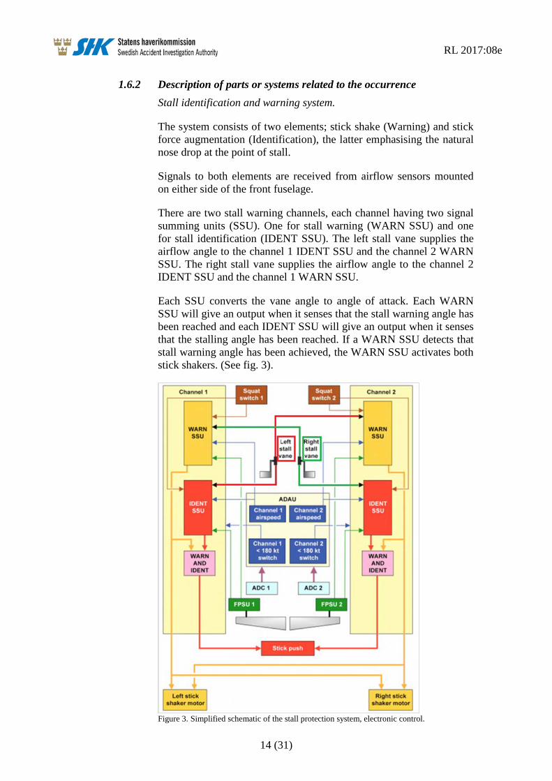
1.6.2 Description of parts or systems related to the occurrence Stall identification and warning system.
The system consists of two elements; stick shake (Warning) and stick force augmentation (Identification), the latter emphasising the natural nose drop at the point of stall.
Signals to both elements are received from airflow sensors mounted on either side of the front fuselage.
There are two stall warning channels, each channel having two signal summing units (SSU). One for stall warning (WARN SSU) and one for stall identification (IDENT SSU). The left stall vane supplies the airflow angle to the channel 1 IDENT SSU and the channel 2 WARN SSU. The right stall vane supplies the airflow angle to the channel 2 IDENT SSU and the channel 1 WARN SSU.
Each SSU converts the vane angle to angle of attack. Each WARN SSU will give an output when it senses that the stall warning angle has been reached and each IDENT SSU will give an output when it senses that the stalling angle has been reached. If a WARN SSU detects that stall warning angle has been achieved, the WARN SSU activates both stick shakers. (See fig. 3).
Figure 3. Simplified schematic of the stall protection system, electronic control.

RL 2017:08e
15 (31)
A channel will only give a stick push if its WARN SSU gives an out-put and its IDENT SSU gives an output. As the two SSU units in a channel take their angle of airflow from different airflow sensors, a failure in one airflow sensor will not result in a spurious push.
The ground condition is sensed from the squat switches installed on the main landing gears. The stall warning and identification are inhib-ited on the ground to prevent nuisance occurrences of stick shake and stick push.
The stall warning is armed as soon as the aircraft leaves the ground. The stick push is not armed until the aircraft has been airborne for about seven seconds.
The stall warning angle and the stalling angle depend on flap setting. When flap 18 degrees are set, as at the event, the stall vane trigger angles are 17 degrees for warning and 25 degrees for identification.
Each IDENT SSU gives an output at a lower vane angle when the rate of change of the vane angle is high.
The rate function incorporated in the Stall Identification SSU is linear and set to advance the AOA warning position by 1.3 degrees per degree/second above a 1.5 ± 0.5 degrees/second dead band.
The alfa-rate function has no limitations either for duration or reduc-tion of the trigger-value and is disabled above 180 ± 5 knots. Speed is supplied by the air data accessory unit (ADAU).
When the aircraft reaches an angle of attack at which stall warning is required the warning SSU’s will activate the stick shake motors. If the angle is allowed to increase, the IDENT SSU, via pneumatic stick force ram, will activate the stick push system and two indications on the instrument panel named STALL VLV A OPEN and STALL VLV B OPEN illuminate. The stick push will not release until both vane angles has been reduced to three degrees below the stick shaker onset angle.
1.6.3 Stall Identification Fault There is a stick push inhibit switch for each channel on the top inboard side of each instrument panel. The switches are used to inhibit a push in the event of failures in the stall identification system.
Each channel has two inhibit switches with amber annunciators and the text IDNT and INHIB. There is also an amber STALL IDNT caption on the central warning panel (CWP).
If a channel senses IDENT AOA without sensing WARN AOA both associated IDNT annunciators and the STALL IDENT caption on the central warning panel illuminates. The channel does not give a push, but will give a push if a stall warning is also detected at a later stage.

RL 2017:08e
16 (31)
To prevent a subsequent false push being given, the channel is inhib-ited by pressing either of the channel’s stick push inhibits switches (IDNT/INHIB) (see fig. 4). Both INHIB annunciators for the failed channel will illuminate and the channel remains inhibited for the rest of the flight. A reset can only be made on the ground. The other channel can still give a push if the stalling AOA is reached.
Figure 4. Stall system annunciators on the instrument panel.
If a false stick push is given, the pilot can overpower the pusher. If both the channel 1 and channel 2 switches are pushed simultaneously, the stall valves will be forced closed and the push will cease. All four INHIB annunciators and all four IDNT annunciators will illuminate. Stick push is lost for the remainder of the flight. (See fig. 5 and 6).

RL 2017:08e
17 (31)
Figure 5. Stall annunciators at different scenarios.
RL 2017:08e
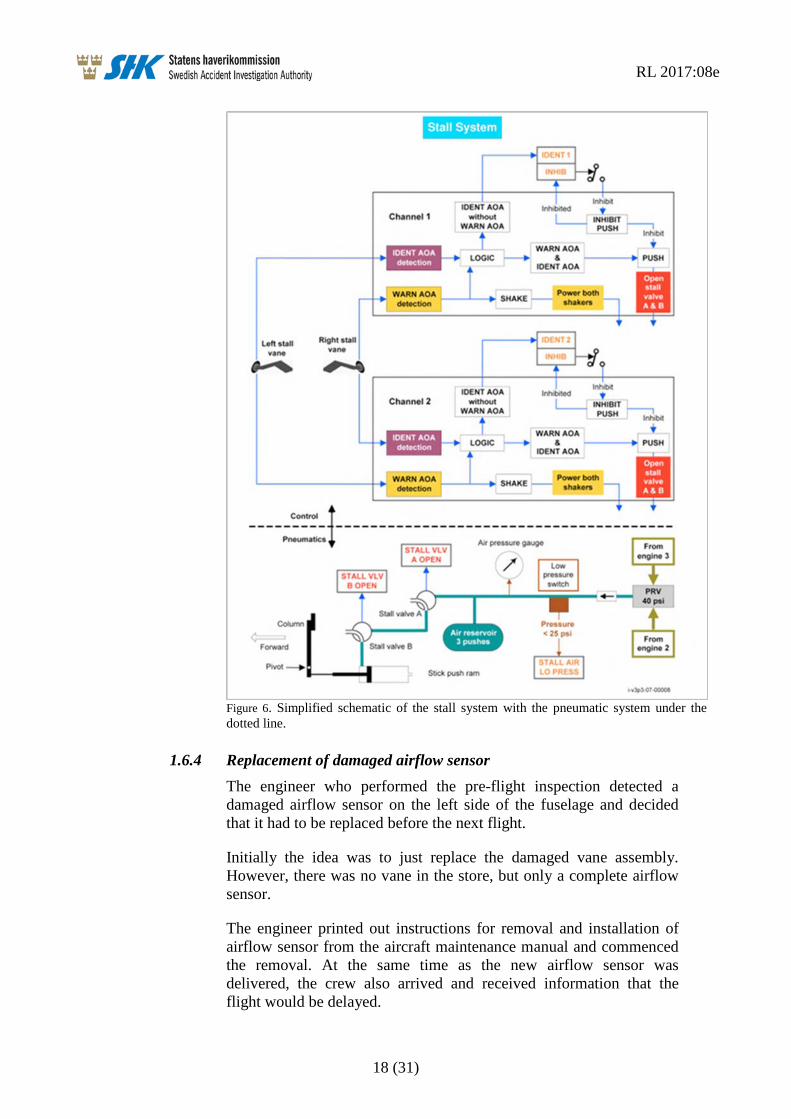
18 (31)
Figure 6. Simplified schematic of the stall system with the pneumatic system under the dotted line.
1.6.4 Replacement of damaged airflow sensor The engineer who performed the pre-flight inspection detected a damaged airflow sensor on the left side of the fuselage and decided that it had to be replaced before the next flight.
Initially the idea was to just replace the damaged vane assembly. However, there was no vane in the store, but only a complete airflow sensor.
The engineer printed out instructions for removal and installation of airflow sensor from the aircraft maintenance manual and commenced the removal. At the same time as the new airflow sensor was delivered, the crew also arrived and received information that the flight would be delayed.

RL 2017:08e
19 (31)
The airflow sensor certificates were reviewed and accepted, and the installation commenced. During the installation, the engineers were interrupted several times by different people who wondered when they should be ready. This was perceived as stressful by the engineers.
When the installation was completed, they browsed through to the last page of text in the manual, where the tests to be carried out after installation usually is written.
The engineers read the test instructions for the “vane assembly”, i.e. installation of the vane, and not for replacement of the airflow sensor. After installation of the vane, only one test of the heating should be performed, which was also done with approved results. However, the engineers thought that this test seemed insufficient, why they decided to also perform a return to service test (RTS) for the airflow sensor and a sensor screen test. Both of these additional tests were performed with approved results.
The tests that were relevant for the change of the airflow sensor, i.a. functional test of the airflow sensor, were not performed.
In the aircraft technical log it was documented that the installation was performed according to the reference AMM 27-33-37 401 which is the installation of the airflow sensor. That a sensor screen test was performed was not documented.
Neither double inspection, according to the maintenance manual, or re-inspection according to the company’s MOE12 was performed.
1.6.5 Aircrafts Maintenance Manual, AMM The maintenance manual describes the tasks of removal and installing the airflow sensor as well as replacing the vane in the same chapter.
The design of the chapter and its underlying tasks do not have clearly defined sections between the two different tasks.
Typically, assembled parts are described as an assembly, in this case the vane is referred to as an assembly.
Airflow sensor is described as a sensor although this component consists of two assembled parts.
12 MOE (Maintenance Organisation Exposition).

RL 2017:08e
20 (31)
1.6.6 Abnormal procedures check list The following checklists for abnormal procedures were relevant to the event. The framed text contains the procedures for which the pilots are supposed to be able to apply by heart, e.g. Memory Items. (See fig. 7–9).
Figure 7. Abnormal and emergency checklist, stall warning.
Figure 8. Abnormal and emergency checklist, stall identification failure.
Figure 9. Abnormal and emergency checklist, stall identification.

RL 2017:08e
21 (31)
1.7 Meteorological information According to SMHI’s analysis: Wind SW/15–20 knots, visibility 6–8 kilometres, cloud 6–8/8 with base 500–700 feet, temperature/dew point +16/+15 °C, QNH 1009 hPa.
The incident occurred during daylight.
1.8 Aids to navigation Not relevant.
1.9 Communications Communication was established with Malmö tower.
1.10 Aerodrome information The aerodrome had status according to AIP Sweden.
1.11 Flight recorders The aircraft was equipped with a DFDR, Digital Flight Data Recorder, and a Quick Access Recorder (QAR) Recorder, and a Cockpit Voice Recorder (CVR).
Data was downloaded from the QAR device as well as the DFDR and the CVR unit was removed from the aircraft. The FDR data and CVR unit was transported by the accident investigation authority staff to the UK Accident Investigation Board AAIB UK for readout. The CVR unit has then been returned to the operator.
1.11.1 Flight Recorders (FDR13, QAR14) DFDR was manufactured by Lockheed with article number 10077A500-803 and serial number 4646.
QAR was manufactured by L3 Communication with article number QAR201-02-00 and serial number 000283449. Flight data was down-loaded by the operator and forwarded to SHK.
The parameter that registers the left angle of attack sensor (AOA), shows that the AOA value have been forty five degrees or more throughout the flight, except for some single registrations during the approach for landing. The lowest registration during the flight was 42.1 degrees AOA.
13 FDR (Flight Data Recorder). 14 QAR (Quick Access Recorder).

RL 2017:08e
22 (31)
1.11.2 Cockpit Voice Recorder (CVR) CVR was manufactured by Fairchild with model number A100A and had article number 93A100-80 and serial number 62829.
The CVR Model A100A has the capacity to record audio on four channels for thirty minutes.
Four audio files with a length of thirty minutes were generated but no sound from the current flight could be analyzed as this had been overwritten.
1.12 Site of occurrence The incident occurred after take-off from runway 17 at Malmö Sturup Airport.
1.12.1 Aircraft after the incident The airflow sensor on the left side was removed.
1.13 Medical and pathological information Nothing has emerged to suggest that the mental or physical condition was impaired before or during the flight.
1.14 Fire There was no fire.
1.15 Survival aspects Not relevant.
1.15.1 Rescue operation Rescue was not relevant at the incident.
The ELT15 of the type KANNAD 406 AP was not activated during the incident.
1.16 Tests and research
1.16.1 Examination of the airflow sensor The left hand side airflow sensor was removed from the aircraft and taken to Exova Materials Technology AB where it was X-rayed under the supervision of SHK. No anomalies could be seen on the x-ray photos.
15 ELT (Emergency Locator Transmitter).

RL 2017:08e
23 (31)
The airflow sensor was sent to Safe Flight Instrument Corporation (SFIC) for test and troubleshooting under supervision by representa-tives of NTSB and FAA16.
The test included inspection of the sensor’s physical condition, functional test, insulation test, disassembly of sensor to isolate faulty components and review of the repair history with the manufacturer.
At the examination it was noted that the vane shaft gear clamp was tight but was not oriented per the drawing. In addition, the two poten-tiometer shaft gear clamps were tight but not oriented correctly. One of the potentiometer clamps was interfering with the spring that connects the two potentiometer gears when the vane was moved to the corresponding stop (See fig. 10 and 11). This resulted in the spring stretching, and returning the vane gear to a neutral position when the vane was let go. When the spring was removed, the vane shaft appeared to balance normally.
Figure 10. Airflow sensor at the examination, right potentiome-ter clamp interfering with the spring.
16 FAA ( Federal Aviation Administration, USA).

RL 2017:08e
24 (31)
Figure 11. Correct orientation of gears, clamps and spring according to the manufacturer manual.
At the examination the unit was found to be 45 to 50 degrees out of specification on all the angle readings.
The unit could operate normally after calibration.
1.16.2 Analysis of repair history of sensor model Analysis of returns since January 2014 shows 46 units came to Safe Flight Instrument Corporation (SFIC) repair station. No units with similar anomalies were found.
1.16.3 Routines at Safe Flight SFIC do not currently use tamper or warranty seals on units. However, the unit is stamped with the date of the latest functional test before delivery. It is not subject to RII17 and therefore no independent inspec-tions of the units are carried out.
1.16.4 BAE Systems prediction of angle of attack BAE Systems has used a design simulator model to process the FDR data in order to try and determine the aircraft’s angle of attack (AOA) at the time stick push started.
BAE systems analysis concluded that, at the time of stick push, the aircraft could have been at an AOA of 16 degrees. Though it was not possible to confirm that AOA and/or vane angle was sufficient to trigger the stall ident system.
17 (RII) Required Inspection Item.

RL 2017:08e
25 (31)
Data in FDR parameters: elevator angle; vertical G and (to an extent) IAS, have significant local variations, which supports the pilot’s report of turbulence which could momentarily increase the AOA over and above steady state values.
1.16.5 Test of the Stall identification and warning system SHK conducted a test in order to understand and clarify how a high rate of change affects the system. The test of the stall system was performed on two of the operator’s aircraft with the registrations SE-DSP and SE-DSY.
Test equipment was installed with annunciators for both stall warning channels stall warning (WARN SSU) and stall identification (IDENT SSU). When the respective annunciator illuminates, that part of the system is activated. To see the angle of the airflow sensors a protrac-tor on each sensor was installed.
The stall system was configured as at the event. Left airflow sensor was set to fully up position (+45 degrees), right sensor at an angle below warning.
This resulted in annunciators illuminated Ident 1 for channel 1 and channel 2 warning on the test equipment. On the instrument panel, the annunciators IDNT 1, STALL IDNT on CWP illuminated and stick shaker was activated, (see fig. 12). The IDNT 1 button was pressed and the INHIB part of the button lit.
Figure 12. Annunciators on the instrument panel and test equipment with left air-flow sensor in position 45 degrees and right in an angle around 0 degrees.
After that, the right vane was moved upwards from zero degrees with small movements, but at a high rate of change to simulate turbulence.

RL 2017:08e
26 (31)
The ident annunciator for channel 2 flashed and the stick push was activated while the “STALL VLV A and B OPEN” annunciators were lit on the instrument panel, figure 13.
Figure 13. Annunciations on the instrument panel and test equipment, at stick push.
Furthermore, the system was tested by positioning left and right vane above the stall identification angle (25 degrees), stick push was acti-vated. Right vane was moved to a position below the stall identifica-tion angle (17 degrees) the stick push was still activated. Left vane was now moved to a position below the angle for stall warning where-by the stick push was deactivated.
1.17 Organisational and management information Braathens Regional Aviation AB is an aviation company engaged in commercial air transport. The operator had a valid Swedish AOC permit No.SE.AOC.0010 issued by the Swedish Transport Agency. The operator uses, inter alia, eleven aircrafts of the model AVRO 146-RJ100, mainly for passenger flights.
1.18 Additional information
1.18.1 Operators maintenance procedures A replacement of an airflow sensor is within an engineer’s authoriza-tion. This means that the engineer may replace test and document the action. Because the replacement is a so-called “Critical Task”, the replacement must be re-inspected by another authorized engineer.

RL 2017:08e
27 (31)
1.18.2 History of Airflow sensor S/N 211 Airflow sensor was manufactured 16 March 1995. After that, the following maintenance actions have been carried out:
• Returned to repair station, 25 October 2004: Airflow sensor, vane rate out of limit. Checked without remark: 5 November 2004
• Returned 24 February 2014: Erroneous angle readings Findings: Found out of calibration and stops out of specifica-tions, plunger balls defective. Action: Replaced washer and plunger balls. Checked/Functional Test: 5 March 2014/12 June 2014. Certified: FAA FORM 8130-3 and EASA dated 13 June 2014.
• Shipped: From SFIC to BAE Systems 23 June 2014, from BAE Systems to BRA 10 February 2015.
• BRA Serviceable Label dated 12 February 2015. • BRA installed S/N 211 in SE-DSP 29 September 2016.
1.18.3 Actions taken The operator
• A Safety Bulletin has been issued specially focused on “Memory Actions” and the current event.
• “Memory Action Sheet” that will be available on board to help the pilot.
• Recurrent training has been introduced regarding the incident and affected systems.
• CVR routines is trained in the flight simulator at OPC18. • The MOE revised 3 October 2016 and updated in accordance
with Commission Regulation (EU) 2015/1536, ED 2016/011/R (AMC+GM), critical maintenance tasks and aircraft continuing airworthiness monitoring.
The type certificate holder
• An information leaflet has been issued to all operators specially focused on “Memory Actions” and the current event. Flight Operations Support Information Leaflet (FOSIL 17-005).
• Introducing changes of the AMM section 27-33-37. The name Vane Assembly has been changed to Vane.
1.19 Special methods of investigations None.
18 OPC (Operators Proficiency Check)

RL 2017:08e
28 (31)
2. ANALYSIS
2.1 The flight Shortly after take-off, when the main wheels were in the air, the stall warning system was activated. By immediately checking the speed and attitude of the aircraft, along with the awareness that an airflow sensor was replaced before the flight, the flight crew could immediate-ly identify the stall warnings as false.
Deactivation of stick shake is not a memory item, which can explain that circuit breakers E5 and E6 were not pulled immediately.
However, deactivation of the stick push is a memory item which in the checklist specifies that both buttons for IDNT 1 and 2 are to be pushed. This was done when the emergency checklists were read. The explanation for this is likely to be found in that the commander previ-ously inhibited IDNT 1 while IDNT 2 did not indicate a fault, which means that the correct action in the arising situation does not appears natural, to deactivate the system. In addition, malfunctions in the stall warning systems are not normally trained in the simulator.
2.2 Technical
2.2.1 Replacement airflow sensor When replacing the airflow sensor, wrong tests were used after instal-lation. Instead of the airflow sensor test, the vane assembly test was used. The term vane assembly leads to the fact that it covers several parts and not just the vane itself. This condition, as well as when the tasks lacks clear boundaries in the manual, can explain why wrong test instructions were used.
The repeated interruptions during the installation have also been a disturbance factor, which probably contributed to the incorrect execu-tion of the task and that the re-inspection was not performed.
The sensor screen test that was performed with approved result could have been approved because it was under stress and that the values were misinterpreted. The only thing that separates the values is a minus sign in front of the full-range value in the end positions.
2.2.2 Logic of the stall warning and identification system BAE Systems calculation of the aircrafts angle of attack AOA showed that at the time of the stick push it could have reached 16 degrees. This means that a 9 degree lowering of the trigger point was required to activate stick push, which corresponds to a rate of change of 8.5 degrees/second.

RL 2017:08e
29 (31)
A rate of change of 8.5 degrees/second can ia.be achieved by: 0.85 degrees motion in 0.1 second, 1.7 degrees motion in 0.2 seconds or 2.55 degrees motion in 0.3 seconds.
The test performed on two aircraft showed that the stick-push will be activated if an airflow sensor is in position above the stall angle (25 degrees) and the other sensor is moved upward from zero degree with small movements, although with high rate.
The pilot’s report and data from the FDR shows that there was turbu-lence. According to the Commission opinion, the most likely explana-tion for stick push activation is that the turbulence caused the change rate of the serviceable airflow sensor at some point to exceed 8.5 de-grees per second. It is not possible to completely rule out any other remaining faults in the system.
2.2.3 History of the faulty airflow sensor Testing and troubleshooting at the manufacturer showed that the clamps of the potentiometers and the clamp of the vane shaft were tight but not orientated according to the drawing. In addition, one of the potentiometer clamps was interfering with the spring that connects the two potentiometer gears when the vane was moved to the corresponding.
This indicates that the sensor at some point been incorrectly assemb-led or manipulated. In the absence of tampering or warranty seals, it is impossible to determine if the device has been delivered incorrectly or if someone has manipulated it at a later stage.
It is likely that the device had not been installed if a broken tampering or warranty seal had been found.
RL 2017:08e
30 (31)
3. CONCLUSIONS
3.1 Findings
a) The pilots were qualified to perform the flight. b) The engineers had authorization to perform the maintenance
action. c) The aircraft had a Certificate of Airworthiness and valid
ARC. d) The pilots immediately identified that the stall warnings as
false and prioritized to keep control of the flight before the troubleshooting began.
e) Memory action to inhibit stick push was not performed. f) Left airflow sensor indicated incorrect angle of attack
throughout the flight. g) Functional test of the airflow sensor was not performed after
the installation. h) The critical task procedure was not performed during the
installation of the airflow sensor. i) The interruptions during the change of the airflow sensor were
a stress factor. j) The tasks does not have clearly defined boundaries between
sections in the manual.
3.2 Causes/Contributing Factors The serious incident was caused by the mix up of test instructions for installation of “Vane assembly” and “Airflow sensor”, which led to a prescribed functional test was not performed and the fault in the air-flow sensor was not detected.
Contributing factors:
• The different component names Vane assembly and Airflow sensor enhance the risk of confusion between tasks.
• The interruptions during the change of the airflow sensor were a stress factor which increased the risk of mistakes.
• Re-inspection after replacement of airflow sensor was not performed.

RL 2017:08e
31 (31)
4. SAFETY RECOMMENDATIONS FAA is recommended to:
• Encourage that components that require specially approved maintenance facilities are sealed to detect unauthorized manipulation. (RL 2017:08 R1)
EASA is recommended to:
• Encourage that components that require specially approved maintenance facilities are sealed to detect unauthorized manipulation. (RL 2017:08 R2)
The Swedish Accident Investigation Authority respectfully requests to receive, by 8 December 2017 at the latest, information regarding measures taken in response to the safety recommendations included in this report.
On behalf of the Swedish Accident Investigation Authority,
Mikael Karanikas Tony Arvidsson


![FZl jbZevghfZ]gblgh -fZjd_jgZy^hkdZ - rl kl_eeZ`^eyihkh[bc - rl ©Nbabq_kdh_jZa\blb_ª fyqbj_abgh\u_ - rl kdZdZedb - rl h[jmqb - rl ^hjh`dZa^hjh\vy -1 rl gZ[hj©d_]ebª - rl dZjlhl_dbi](https://img.dokumen.tips/doc/110x75/5ece591ea59d69109e45e484/fzl-jbzevgh-fzgblgh-fzjdjgzyhkdz-rl-kleezeyihkhbc-rl-nbabqkdhjzablb.jpg)