Embed Size (px)
Citation preview

Final Report
Aluminum Manganese Molten Salt Plating WP 9903
Naval Air Systems Command
Materials Engineering Division Patuxent River, Maryland
June 2006

I ~ u b l k n k u m a ~ ~ r n r u t h l ~ n r d b . 1 1 ~ d ~ ~ ~ ~ ~ @ 1 6 ~ . Thm fnnn k h m d e d Ibr rrktss d un-lkd o n m l a d Wwkd IrrlhnMllm. Inrdudlm amtwd fw MAvAIR nubihWU. RMI fubm *mm
L
LYBT PROORUlCbllEg WHWE lUPIBCT N A m 18 m E b III THEB MATERIAL
NRqflrR INOe&hNIC COA.-TIH.IGS mPE2 Y.9.7,~ WFORYITION CA-Y Chwk CU mu qM: wTe&*iml Paper b TICMmI Mmn~mI El Prmnnbtbn A b h c t Rat. Mlde 0 Spsm
DVWidaa CD O~ubWeetlon FaeiShaet R B ~ h ~ P e m p h l e t Graphlea/Dlspley web (krcrhrde ~ s b aidmsj. &ww. cs +em. o r a
Conhct#: - -. Other (spec/@)):
PURPOSE Vbnue 4 -(a), W d d d n n , or plblaWan b Mkh 01Is mtmdel hm bea wd: '
. - ra mquM, plme pl- In !3m%bn 1. mr ̂"". I"
C L M E D FOR O ~ N PUBllCATlON 1 . . I
U V U R FORM m2W1 (WJ

TABLE OF CONTENTS
Page
1. INTRODUCTION ...............................................................................................................1 1.1 Background..............................................................................................................1 1.2 Objectives of the Demonstration .............................................................................2 1.3 Regulatory Drivers...................................................................................................3 1.4 Stakeholder/End-User Issues ...................................................................................4
2. TECHNOLOGY DESCRIPTION .......................................................................................5 2.1 Technology Development and Application .............................................................5 2.2 Previous Testing of the Technology ......................................................................18 2.3 Factors Affecting Cost and Technology Performance...........................................22 2.4 Advantages and Limitations of the Technology ....................................................22
3. DEMONSTRATION DESIGN .........................................................................................23 3.1 Performance Objectives .........................................................................................23 3.2 Selecting Facilities.................................................................................................27 3.3 Facility History/Characteristics .............................................................................27 3.4 Present Operations .................................................................................................31 3.5 Pre-Demonstration Testing and Analysis ..............................................................31 3.6 Testing and Evaluation Plan ..................................................................................31 3.6.1 Demonstration Set-Up and Start-Up.........................................................31 3.6.2 Period of Operation...................................................................................32 3.6.3 Amount/Treatment Rate of Material to be Treated ..................................32 3.6.4 Operating Parameters for the Technology ................................................32 3.6.5 Experimental Design.................................................................................32 3.6.6 Product Testing .........................................................................................34 3.6.7 Demobilization..........................................................................................34 3.6.8 Health and Safety Plan..............................................................................34 3.7 Selection of Analytical/Testing Methods ..............................................................34 3.8 Selection of Analytical/Testing Laboratory...........................................................34 3.9 Management and Staffing ......................................................................................34 3.10 Demonstration Schedule ........................................................................................34
4. PERFORMANCE ASSESSMENT ...................................................................................35 4.1 Performance Criteria..............................................................................................35 4.2 Performance Confirmation Methods......................................................................39 4.2.1 Data Collection .........................................................................................45 4.2.2 Experimental Controls ..............................................................................45 4.3 Data Analysis, Interpretation and Evaluation ........................................................45
5. IMPLEMENTATION ISSUES .........................................................................................46 5.1 Environmental Checklist........................................................................................46 5.2 Other Regulatory Issues.........................................................................................46
i

5.3 End-User/Original Equipment Manufacturer (OEM) Issues .................................46
6. REFERENCES ..................................................................................................................46
7. POINTS OF CONTACT....................................................................................................47
APPENDICES ...................................................................................................................48 Appendix A: Aluminum-Manganese Plating Draft Standard Operating Procedure..........48 Appendix B: Aluminum-Manganese Plating Local Process Specification .......................65 Appendix C: Aluminum-Manganese Plating Mock Startup Procedure.............................75 Appendix D: Analytical Methods Supporting the Experimental Design ..........................77
ii

LIST OF TABLES
Table 1-1. Permissible Exposure Limits.........................................................................................4 Table 3-1. Performance Objectives ..............................................................................................24 Table 3-2. Candidate Components for Aluminum-Manganese Plating at NADEP North Island 28 Table 3-3. Experimental Design Matrix Template for Component Plating Parameter
Optimization ..........................................................................................................................33 Table 4-1. Performance Criteria ...................................................................................................35 Table 4-2. Expected Performance and Performance Confirmation Methods ...............................40
LIST OF FIGURES
Figure 2-1. Proposed and Existing Electroplating Process Sequences...........................................7 Figure 2-2. Molten Salt Plating Equipment Configuration.............................................................8 Figure 2-3. Aluminum-Manganese Depot System .........................................................................9 Figure 2-4. Heating System Control Panel and Chemical Add Funnel ..........................................9 Figure 2-5. Plating Tank .................................................................................................................9 Figure 2-6. Plating Tank Ventilation Plenum...............................................................................10 Figure 2-7. Inside Surface of Ventilation Plenum ........................................................................10 Figure 2-8. Plating Tank with Heating and Insulation Installed...................................................10 Figure 2-9. Anode and Cathode Cable Hoist System ...................................................................11 Figure 2-10. Rectifier with Anode and Cathode Cables Attached ...............................................11 Figure 2-11. Water Rinse Tank.....................................................................................................12 Figure 2-12. Inside of Water Rinse Tank .....................................................................................12 Figure 2-13. Anode and Cathode Acid Etch Tank........................................................................13 Figure 2-14. Ventilation Smoke Test with Chemical Add Funnel Inserted in Ventilation Plenum13 Figure 2-15. Surface Structure of Al-Mn Plated Deposit for 15wt% Manganese.........................21 Figure 3-1. Map of San Diego and Vicinity .................................................................................29 Figure 3-2. Map of NADEP North Island and Location of Proposed Facility .............................30
iii

LIST OF ACRONYMS AA Atomic Absorption Spectroscopy APPTech Aviation Pollution Prevention Technology Program CFR Code of Federal Regulations DoD Department of Defense ESTCP Environmental Security Technology Certification Program ICP Inductively Coupled Plasma IVD Ion Vapor Deposited JTP Joint Test Protocol MSDS Material Safety Data Sheet NADEP Naval Aviation Depot NAVAIR Naval Air Systems Command NAWCAD Naval Air Warfare Center Aircraft Division NIST National Institute for Standards and Technology OEM Original Equipment Manufacturer OSHA Occupational Safety and Health Administration PEL Permissible Exposure Limit PNOR Particulates Not Otherwise Regulated RCRA Resource Conservation and Recovery Act SERDP Strategic Environmental Research and Development Program TWA Time Weighted Average USEPA United States Environmental Protection Agency
ACKNOWLEDGEMENTS
The following personnel significantly contributed to the execution of this demonstration project: Erin Beck, Naval Air Systems Command Patuxent River James Green, Naval Air Systems Command Patuxent River Steven Brown, Naval Air Systems Command Patuxent River Alcide Richards, Naval Air Depot North Island Edward Duffy, Naval Air Depot North Island Raymond Lucy, Naval Facilities Engineering Service Center Port Hueneme
iv

ABSTRACT
In 1999 an effort was begun to evaluate the efficacy of a production size aluminum-manganese molten salt plating system. The technology was previously demonstrated at a smaller scale through efforts overseen by Naval Air Warfare Center, Warminster and Naval Air Systems Command, Patuxent River. The effort begun in 1999 culminated in a 200-gallon demonstration system installed at Naval Air Depot North Island. In mid-September 2005 the aluminum-manganese plating system located at the depot was loaded with an initial batch of plating chemicals. However, after loading 25 gallons of chemicals into the tank the researchers were directed by the depot Environmental Office to stop due to visible stack emissions. Initially a scrubber was planned for the process that would remove alumina particulate and neutralize hydrogen chloride vapor generated by the plating system. However, the scrubber was not included in the final design. The San Diego Air Pollution Control District concluded that a scrubber was not needed based on estimated emissions the researchers submitted in the air permit application. Although the estimated content and amount of emissions was acceptable to the District they did not understand that the emissions would be visible. The District does not allow any visible emissions from any stack, a rule that the researchers were unaware of until personnel from the depot Environmental Office observed the emissions and directed the process to be stopped. Several mechanical methods and addition of fume suppressant to the bath were implemented in an effort to reduce emissions visibility. Emissions were significantly reduced but not enough to satisfy the District rule.
Fuming of the bath resulted in loss of bath chemicals, as well as crusting of ventilation and plating tank inner surfaces. The crust is a hard, non-brittle alumina coating that forms when volatile bath components condense on relatively cooler surfaces. Both issues hindered the ability to operate the process. Bath composition could not be kept constant, and crust formed rapidly such that the entry point for parts into the tank began closing up with crust. Thermal insulation was installed prior to operation to mitigate crust formation, but did not work due to the small thermal mass of the chemicals loaded into the process vessel. The melt never reached the hot zone level of the banded main heater or the mixer that would have allowed for more efficient heat transfer. If it is determined that this process is needed in the future an R&D effort is recommended to find a suitable bath chemistry that eliminates fuming.
v
Final Report
Aluminum Manganese Molten Salt Plating
Naval Aviation Systems Command Materials Engineering Division
Patuxent River, Maryland
June 2006
1. Introduction 1.1 Background Military aircraft are often exposed to environmental conditions that accelerate corrosion of metallic aircraft components. Cadmium coatings, which have been used for over 70 years, are a key technology used to reduce corrosion of steel aircraft components. Depositing cadmium by electroplating is a relatively inexpensive and simple process. However, strict environmental and occupational safety and health regulations drive the search for alternative coatings. Compliance with hazardous waste regulations requires strict handling, storage, and disposal procedures, and expensive disposal fees. Non-compliance with regulations may result in large fines or lawsuits. Several alternatives to cadmium plating currently exist. Cadmium alternatives can be classified into two basic categories: zinc-based alternatives and aluminum-based alternatives. Zinc-based alternatives, such as tin-zinc and zinc-nickel, are commercially viable but can lead to environmentally assisted cracking, or “in-service re-embrittlement”, of high strength steels. Low open circuit potentials and the generation of hydrogen cause cracking. As a result, zinc-based alternatives must be approached with caution during consideration for use in high strength steel system critical applications. Aluminum-based alternatives, such as Ion Vapor Deposited (IVD) aluminum, sputtered aluminum, solvent-based electroplated aluminum (AlumiPlate), and aluminum-manganese molten salt plating, generally alleviate the concerns of environmentally assisted cracking of high strength steels. IVD aluminum is a commercially available process, however capital equipment,
1

maintenance, and energy costs are relatively high. Sputtered aluminum is in the process of becoming commercially available and provides for coating the internal diameters of components that are IVD aluminum coated. The IVD and sputter processes, however, are limited in capability to coat small internal diameters and process bulk quantities of electrical connectors and fasteners. AlumiPlate is a commercially available process, but utilizes a toluene-based electrolyte that contains pyrophoric organometallic aluminides. Capital cost and environmental, safety, and health regulations of toluene and the electrolyte have thus far hindered large-scale implementation of the AlumiPlate process beyond the current sole source. Aluminum-manganese molten salt plating is not a commercially available process. DoD pursued electroplated aluminum-manganese as an alternative for cadmium based on positive results from laboratory-scale investigation. The project was supported by the Navy's Aviation Pollution Prevention Technology Program (APPTech) and the Environmental Security Technology Certification Program (ESTCP). The proposed aluminum-manganese electroplating process was relatively straightforward. Components would be cleaned and prepared similarly to components prepared for cadmium electroplating, dipped into an enclosed 190°C aluminum-manganese plating tank, and finally dipped into a water rinse tank to remove residual plating solution. The entire process must be more enclosed and requires a relatively robust ventilation system with a scrubber to contain hydrogen chloride and aluminum chloride fumes generated by the plating bath. The primary reason aluminum-manganese plating was pursued was that it was expected to retain the technical performance of cadmium and reduce some of the regulatory burden by removing plating, refurbishing and washdown rinse water from Resource Conservation and Recovery Act (RCRA) hazardous waste classification. It would also remove cadmium from more aircraft components than currently anticipated with zinc and other aluminum-based alternatives. 1.2 Objectives of the Demonstration The goals of this demonstration project were to demonstrate and validate that electroplating of aluminum-manganese from a molten salt bath is technically feasible and commercially viable for a production-scale process, and to transition aluminum-manganese coatings for use on high strength steel, flight critical components currently coated with cadmium. A 200-gallon production representative aluminum-manganese plating system was designed and installed at the Naval Aviation Depot (NADEP) North Island, CA. The system was targeted as a one-for-one replacement for the cadmium-cyanide plating tanks currently used at the depot. A Local Process Specification and Standard Operating Procedure were written for operation and maintenance of the aluminum-manganese plating system. The performance of aluminum-manganese plating was planned for evaluation as outlined in Section 3.1. First, low-strength steel test coupons would be evaluated in accordance with selected tests from the JTP BD-P-1-1 “Validation of Alternatives to Electrodeposited Cadmium for Corrosion Protection and Threaded Part Lubricity Applications.” Low risk components would then be recommended for field test. Next, high strength steel test coupons would be evaluated in accordance with the “High Strength Steel Joint Test Protocol for Validation of Alternatives to Low Hydrogen Embrittlement Cadmium for High Strength Steel Landing Gear and Component Applications.” Finally, high strength steel components would be recommended for field test.
2

The plating system was installed and charged with an initial increment of plating bath chemicals. However, the system was shut down before plating could be attempted due to visible plating bath fume generation and subsequent issues that could not be resolved without substantial time and funding. It was determined that the plating bath would require an inherent fume suppressant for the process to be feasible in a production size system. A scrubber would be sufficient to capture and treat the fumes, but would not address crust formation. Incorporation of fume suppressant would mitigate both issues. 1.3 Regulatory Drivers Environmental, health and safety regulations continue to drive the search for alternatives to cadmium plating. Cadmium plating results in numerous environmental burdens. Cadmium and cyanide waste products are generated during all stages of the cadmium plating lifecycle. The cadmium plating process generates spent plating bath and rinse water, both of which contain cadmium and cyanide; refurbishment of cadmium plated components involves grinding and cleaning, which results in cadmium-containing rinse water and shop cloths; washing of Defense systems generates rinse water contaminated with cadmium; and finally, components coated with cadmium must be disposed. Wastewater treatment sludge from electroplating operations is F006 hazardous waste per Title 40, Part 261, Section 31 of the CFR. Spent cyanide plating bath solutions from electroplating operations are F007 hazardous waste per Title 40, Part 261, Section 31 of the CFR. Electroplated aluminum-manganese was expected to reduce some of the environmental burden associated with the use of cadmium. Aluminum-manganese plating, refurbishing, and washing wastes are not RCRA hazardous waste, however, waste aluminum-manganese plating solution is RCRA hazardous waste. Waste plating solution may be treated with sodium hydroxide solution to form non-hazardous waste. A hazardous waste permit is required to perform treatment. In addition to requiring compliance with hazardous waste requirements, cadmium plating poses a serious health risk to workers. Workers are exposed to cadmium during the plating process, as well as during refurbishing and washing plated components. Workers may be exposed to cadmium through the inhalation route during initial bath makeup and refurbishment of cadmium plated components. Cadmium oxide in powder form is typically used to charge the plating tank, and may result in generation of cadmium dust at a concentration greater than the Occupational Safety and Health Administration (OSHA) Permissible Exposure Limit (PEL) of 5 µg/m3. The PEL is very stringent because cadmium is a known human carcinogen and heavy-metal poison. Compliance with this regulation is met by implementation of engineering controls, handling procedures, and personal protection equipment. Refurbishment of aircraft components includes grinding of the components as part of the preparation and cleaning process. Grinding results in generation of cadmium particulate. In addition to inhalation, workers may also be exposed to cadmium by ingestion. Cadmium may be easily transferred onto the surface of the skin when a worker touches a cadmium plated component or plating rack. If proper hygiene is not exercised then transfer of cadmium from hand to mouth is highly likely. In addition to reducing environmental regulatory burden, aluminum-manganese plating could potentially reduce health risk to workers compared to cadmium. The OSHA PELs for aluminum, manganese, and hydrogen chloride are three (3) orders of magnitude greater than the
3
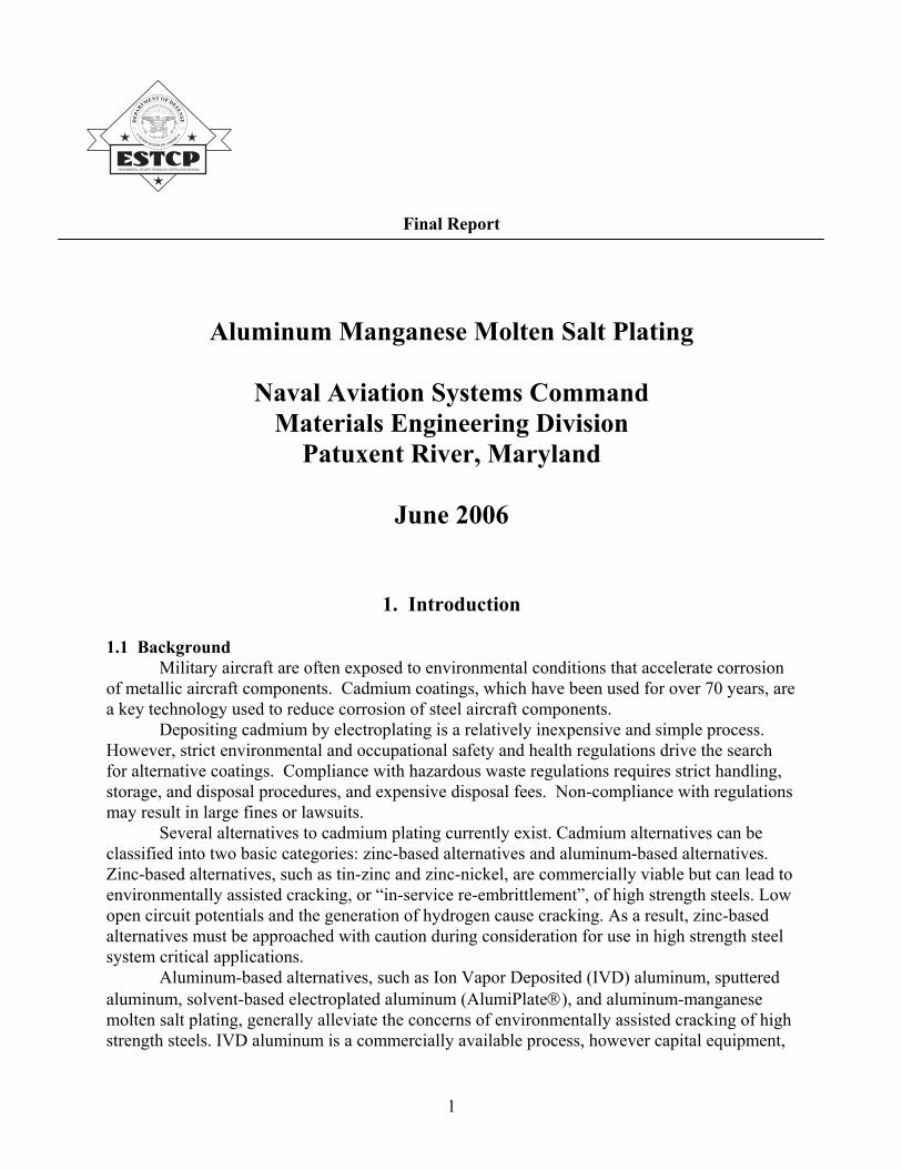
PEL for cadmium (see Table 1-1). Theoretically, less stringent engineering controls and personal protective equipment would be required. However, as stated previously the aluminum-manganese plating system that was designed required relatively expensive engineering controls. Implementation of a suitable fume suppressant may have mitigated the need for such controls.
Table 1-1. Permissible Exposure Limits Material 1Permissible Exposure Limit
(milligrams per cubic meter) Cadmium 0.005 Cyanides 5 Aluminum Total Dust 15 Aluminum Respirable Fraction 5 Manganese Compounds 5 (Ceiling Value) Manganese Fume 5 (Ceiling Value) Hydrogen Chloride 7 PNOR Total Dust 15 PNOR Respirable Fraction 5 1. 8-hr Time Weighted Average (TWA), except manganese
The PEL for cadmium is taken from 29 CFR Part 1910.1027. The PELs for all other materials are taken from 29 CFR Part 1910.1000 Table Z-1. The PELs for manganese are ceiling values, and all other PELs are based on an 8-hour time weighted average (TWA). The PEL for cadmium is listed as 5 micrograms per cubic meter and is converted to milligrams per cubic meter for inclusion in Table 1.
1.4 Stakeholder/End-User Issues The users of cadmium alternative technology could be any current user of cadmium plating technology, including Navy depots, Army, Air Force, NASA, and original equipment manufacturers (OEM) such as Boeing. Most air, land or sea components currently plated with cadmium could potentially be plated with aluminum-manganese. Potential military programs include: Joint – H-60, V-22, F-35; Air Force – ACM, AGM-86, B-1B, B-2, B-52H, E-3A, E-4B, E-8A, E-767, FO-E-3A, F-22, IUS, KC-135, Minuteman, Peacekeeper; Army – Avenger, CH-47; NASA – Shuttle Upper Stage; Navy – CH-46, E-6, F/A-18, S-3, F-14. Several stakeholder/end-user requirements generally include that the alternative technology be as close to a "drop-in" replacement as possible, that the alternative technology perform in the field as well as or better than cadmium, and that the alternative technology be easily maintainable (the process and the coating). In this case, the aluminum-manganese plating system installed at the depot was essentially not maintainable. Visible fuming of the bath resulted in loss of bath chemicals, as
4

well as crusting of ventilation and plating tank inner surfaces. The crust is a hard, non-brittle alumina coating that forms when volatile bath components condense on relatively cooler surfaces. Both issues hindered the ability to operate the process. Bath composition could not be kept constant, and crust formed so quickly that the entry point for parts into the tank was closing up with crust. Insulation was installed prior to operation to mitigate crust formation but did not work due to the small thermal mass of the chemicals loaded into the process vessel. The melt never reached the hot zone level of the banded main heater and the mixer that would have allowed for more efficient heat transfer. Another anticipated maintainability issue was moisture addition to the plating solution. Significant amounts of moisture introduced into the bath, either by moist air or wet components, may have adversely impacted the performance of the bath and require periodic removal of moisture induced precipitate. The depot system was designed to minimize introduction of moisture into the plating solution by installation of a robust gate valve over the opening into the plating tank.
2. Technology Description
2.1 Technology Development and Application Aluminum-manganese molten salt plating is conducted in a salt bath of nominal weight
percent composition of 79% aluminum chloride, 10% sodium chloride, 10% potassium chloride, and 1% manganese chloride. Application of direct current to 1100 aluminum alloy anodes causes an aluminum-manganese deposit to form on the steel component surface. The deposit provides anodic protection of the steel, good surface for paint adhesion due to hill-and-valley type surface, and lubricity similar to a cadmium plated surface.
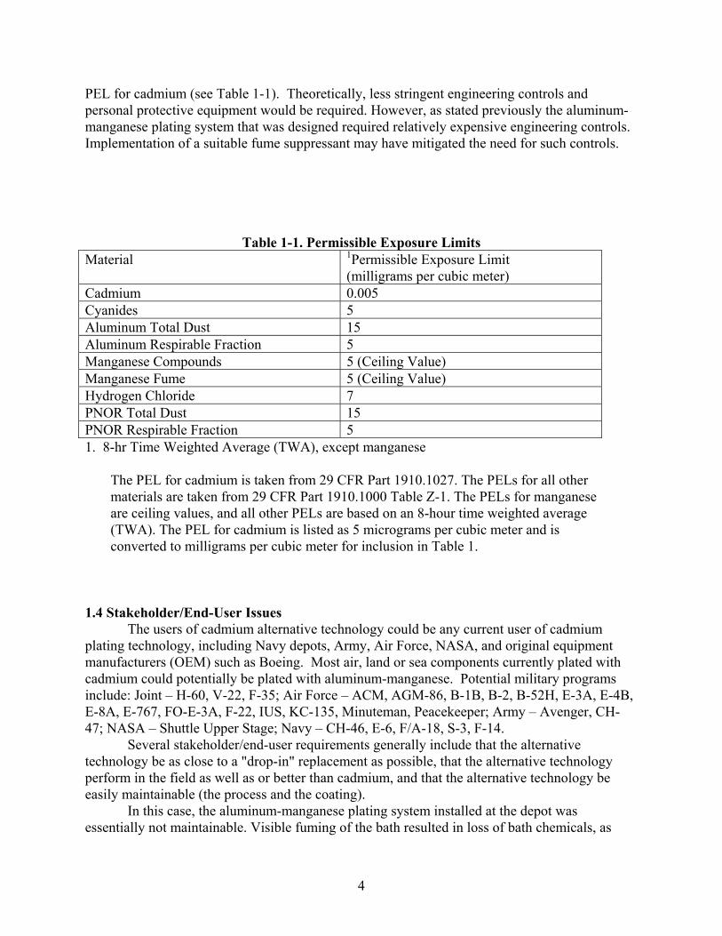
An overall schematic of the proposed aluminum-manganese plating process sequence is shown in Figure 2-1. Figure 2-2 exhibits the as built aluminum-manganese plating equipment configuration. Figures 2-3 and 2-4 show the as-built process, Figure 2-5 shows the plating tank prior to installation of the heaters and insulation, Figures 2-6 and 2-7 show the ventilation plenum that captured fumes from the plating tank, and Figure 2-8 shows the plating tank with insulation installed and heaters (underneath the insulation) hooked up to the controller (controller not shown in the figure). Figure 2-9 shows the hoist system used to hold the anode and cathode cables at working level, and Figure 2-10 shows the cables attached to the pulse reverse rectifier. Figures 2-11 and 2-12 are of the first rinse tank and show the pump and plumbing used for water recirculation. Figure 2-13 is of the nitric acid etch tank used to etch the anode and cathode fixtures. And, Figure 2-14 is of the test conducted to verify that sufficient ventilation was available to capture dust generation during chemical add operations with the funnel in place.
A brief explanation of the processing steps follows; see Standard Operating Procedure in Appendix A for detail. 1.) Clean and load anode fixture into plating bath, 2.) clean, grit blast, and mask component, 3.) attach component to cathode fixture and lower into plating bath as soon as possible to minimize iron oxide formation on the component surface, 4.) make electrical connections from rectifier to anode and cathode fixture, 5.) select a pre-programmed plating
5

6
sequence from the rectifier laptop computer and initiate plating sequence, 6.) plating is performed at approximately 180 amps/square feet and 190°C with forced convection, 7.) once plating is complete lift cathode fixture and component and dwell in upper plenum until fuming subsides (up to 5 minutes), 8.) lift component out of plenum and into ventilated, water rinse tank that is maintained at 8 to 8.5 pH, 9.) lift component out of the rinse tank and spray rinse component with water, 10.) unrack, post-plate bake for hydrogen embrittlement relief and conversion coat. Hydrogen is formed during the rinsing step (not the plating step, as in other aqueous plating methods) and therefore a post-plate bake is still required for hydrogen embrittlement relief.

Figure 2-1. P
P
ComMask
Component
CCom
Dean
E
Mask Component
roposed and Existing Electroplating Process Sequences
roposed Aluminum-Manganese Electroplating Process Sequence
Bake
Water Rinse
Water Rinse
Electroplate 80-90 F
10-15 min.
Clean Component
Rack ponent
Conversion Coat
Bake
Water Spray Rinse
Water Rinse, maintain pH 8 with NaOH)
Electroplate 190 C
15 min.
Rack Component
lean ponent
Conversion Coat
Acid Dip
Ambient Water Rinse
Hot Water Rinse
Electrolytic Clean
Vapor Degrease
Grit Blast
grease d Grit
Blast
Spent Bath RCRA
hazardous waste
Al2O3, Al(OH)3 in wastewater
xisting Cadmium-Cyanide Electroplating Process Sequence
OR
Spent Bath RCRA
hazardous waste
Rinse Water RCRA
hazardous waste
Rinse Water RCRA
hazardous waste
Water Rinse
7

8
Figure 2-2. Molten Salt Plating Equipment Configuration

9
Figure 2-5. Plating Tank Figure 2-4. Heating System Control Panel and Chemical Add Funnel
Figure 2-3. Aluminum-Manganese Depot System
Control Panel
Funnel
10
Figure 2-8. Plating Tank with Heating and Insulation Installed
Figure 2-7. Inside Surface of Ventilation Plenum
Figure 2-6. Plating Tank Ventilation Plenum

Figure 2-9. Anode and Cathode Cable Hoist System
Figure 2-10. Rectifier with Anode and Cathode Cables Attached
11

12
Figure 2-12. Inside of Water Rinse Tank
Figure 2-11. Water Rinse Tank
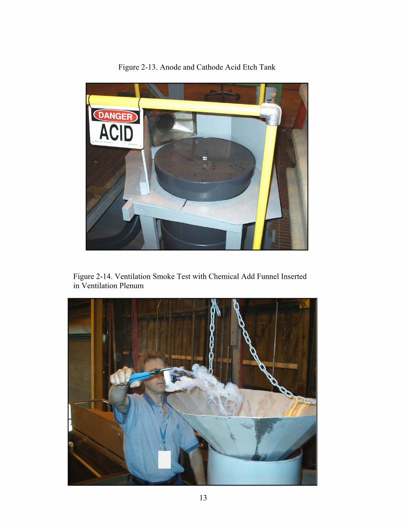
13
Figure 2-14. Ventilation Smoke Test with Chemical Add Funnel Inserted in Ventilation Plenum
Figure 2-13. Anode and Cathode Acid Etch Tank

Local Process Specification and Standard Operating Procedure documentation was
developed as part of the demonstration project and is included in the Appendices. Molten salt plating is a novel process that presents a number of safety concerns. These concerns were identified and addressed by conducting a Process Hazards Analysis. A Mock Startup exercise was developed and conducted prior to startup to allow dry runs and adjustment of the process prior to addition of plating chemicals to the system. The Mock Startup is included as Appendix B.
In mid-September 2005 an initial load of about 25 gallons of plating bath chemicals was prepared and loaded into the depot system. One- to two-gallon batches of plating bath were mixed and heated in large beakers on hot plates on site. The "fused" salt bath batches were cooled into solid forms of plating bath that were lowered into the plating tank. The fusing process generated a relatively large amount of opaque white fuming that was captured by the ventilation system on site. Although permitting requirements were previously accomplished through the depot Environmental Office, the visible emissions were not allowed and the fusing process was stopped. It was determined based on calculation that enough chemical volume had been added to the tank such that once the tank was heated and the chemical melted the bath level would barely reach the tank impeller. The balance of chemicals could then be added batch-wise in powder form and effectively incorporated into the bath. The plating tank was designed to minimize emissions and so it was decided to continue and apply heat to the plating tank. As heat was applied to the plating tank the amount of visible emissions coming from the tank was substantial despite numerous efforts to control the emissions, and the system was shut down.
Initially a scrubber was planned for the system but was not included. The San Diego Air Pollution Control District concluded that a scrubber was not needed based on estimated emissions the researchers submitted in the air permit application. Although the estimated content and amount of emissions were acceptable to the District they did not understand that the emissions would be visible. The District does not allow any visible emissions from any stack, a rule that the researchers were unaware of until personnel from the depot Environmental Office saw the emissions and directed the system be shut down.
The researchers implemented several mechanical methods plus addition of chemical fume suppressant to the bath in an effort to reduce emissions visibility. Emissions were significantly reduced but not enough to satisfy the District rule. The following methods to reduce visible emissions were considered: • Install scrubber – not implemented. Minimum 6-month lead time for equipment and permit
modification. Crust buildup and material losses would still be issues. • Redirect emissions into existing rinse tank to “scrub” emissions – not implemented. Did not
have sufficient blower capacity available. It would be risky to cut into the ventilation system with 25 gallons of bath in the plating tank. Crust buildup and material losses would still be major issues.
• Reduce ventilation draw from the plating tank hood until just enough flow to prevent fumes from escaping into the room – implemented. Emissions were reduced but still significantly visible.
• Partially close off plating tank opening, leaving just enough room to make chemical adds through the funnel – implemented. Emissions were reduced but still significantly visible.
• Add Krytox as fume suppressant – not implemented. In lab evaluation Krytox significantly reduced fuming, but also significantly hindered ability to plate and required considerable
14

clean up effort afterward. Krytox film remains on equipment surfaces and is difficult to remove.
• Add Fumetrol as fume suppressant – implemented. In lab evaluation fumes increased initially due to the water in Fumetrol reacting with the bath. After the initial reaction subsided fuming was greatly reduced and ability to plate was enhanced. One gallon of Fumetrol was added to the bath. Fuming increased initially, then decreased but was still considerably visible coming out of the stack. A second gallon of Fumetrol was added with the same result.
Fuming of the bath also resulted in loss of bath chemicals, as well as crusting of
ventilation and plating tank inner surfaces. The crust is a hard, non-brittle alumina coating that forms when volatile bath components condense on relatively cooler surfaces. Both issues hindered the ability to operate the process. Bath composition could not be kept constant, and crust formed so quickly that the entry point for parts into the tank was closing up with crust. Thermal insulation was installed prior to operation to mitigate crust formation but did not work due to the small thermal mass of the chemicals loaded into the process vessel. The melt never reached the hot zone level of the banded main heater and mixer that would have allowed for more efficient heat transfer. It is recommended that future pursuits of molten salt plating include an research and development effort to find a suitable bath chemistry that eliminates fuming.
Numerous processing issues and "lessons learned" that were encountered during the dry
runs and actual startup include: • Emissions: substantial hydrogen chloride and aluminum chloride fumes made visible by
inclusion of alumina particles. The visibility of the fumes was more substantial than anticipated. A scrubber would be required to remove particulates and neutralize acidity. Alternatively, or in conjunction, a suitable fume suppressant or inherently low vapor pressure bath chemistry could address fuming. Fumes also leaked out of equipment inside the process site and significantly contributed to the decision to shut the process down. Leakage occurred through the gate valve mechanism packing (used for positive closure of the plating vessel). Fumes that leaked into the room deposited an acidic film on all surrounding surfaces. All surfaces were neutralized with sodium bicarbonate and thoroughly washed with water. It is imperative that future efforts incorporate absolutely leak-proof equipment design or fume-free chemistry to prevent personnel exposure to acidic fumes and surfaces, and corrosion of surrounding surfaces and equipment.
• Significant buildup of acidic alumina crust on equipment inner surfaces was also related to bath volatility at temperature. The process equipment design included heaters and insulation to help mitigate crust buildup, as crust forms when bath fumes condense and solidify on relatively cool surfaces. The mitigations were not effective for a process that was not fully loaded though and significant crust build-up occurred around the inner circumference of the plenum collar section located between the gate valve and the plating tank entry/opening. Crust was also believed to have developed on the underside of the gate valve. Intrusion of acidic plating bath fumes penetrated beyond the valve's protective Halon-coated components. A more robust design was needed.
• Anode and cathode fixtures were too intricate and cumbersome to handle effectively. A much simpler design would be required for depot use.
• Obtaining a sample of the plating bath without exposing the worker to fumes is a key issue that had not been resolved. The current bath analysis procedure requires a non-hydrated
15

sample be obtained. The only known method to keep the bath moisture-free when extracting a sample is to take the sample from a hot (and thus fuming) bath, using a syringe and quickly transfer to sample container to which a known amount of nitric acid diluent is added after the specimen cooled somewhat. Developing an analysis procedure for a hydrated sample was recognized but not resolved.
• Chemical-addition procedures were more cumbersome than anticipated. During the dry run drills, it became apparent that the chemical addition equipment and handling procedures were labor intensive, cumbersome, and became chemical exposure risks. The method used was to insert a large funnel into the ventilation plenum above the plating tank entry point, and pour chemicals through the funnel into the open plating tank. It is imperative that sufficient ventilation be used to mitigate exposure of workers to plating bath fumes and dust generated during the process of pouring powder chemicals into the funnel, while avoiding excessive feed powders being carried away in the strong ventilation draft.
• The molten salt bath requires at least a 4-hour dwell time after chemical-adds are made to the plating tank. This presents a potential logistics issue and careful planning of sampling and chemical-adds processes are required to maintain bath composition.
• When a plated component is transferred out of the plating tank and into the rinse tank a large amount of hydrogen chloride fumes is generated. Sufficient ventilation is imperative to prevent worker exposure to fumes. Additionally, it is believed that rinsing in water drives hydrogen into the component and necessitates a post-plate bake for hydrogen embrittlement relief. A non-aqueous rinse process could mitigate both fume generation and hydrogen embrittlement.
• The plating tank draining procedure was cumbersome, labor intensive, and time consuming. The process involved placing 55-gallon drums, equipped with custom-made lids to accommodate ventilation, in the pit area below the plating tank. A significant amount of manhandling of the drums and tank outlet and ventilation lines was required and would be a worker exposure concern. A more automated system or different equipment configuration could potentially improve the process.
• Molten salt plating baths are composed of several salts and aluminum chloride. When mixed and heated, the raw materials form a near-eutectic to melt at a temperature well below that of any of the neat constituents. This "fusing" process was conducted for 25 gallons of plating bath in 1 to 2-gallon batches by hand mixing in beakers placed on hot plates. The pre-fused bath was allowed to cool and solidify into molds. The molded chunks were loaded into the plating tank and heat was gradually applied to melt the chunks. The premise was that some pre-fused plating bath must be initially loaded into the plating tank so its liquidus temperature was sufficiently low. Then the balance of chemicals needed to fill the tank could be added batch-wise in powder form and effectively incorporate with the initial pre-fused liquid charge. The process is labor intensive and cumbersome. In retrospect, a plating tank with a mixing system capable of mixing the powders and highly viscous "slush" that forms as the fusing process progresses would be more suitable.
• As heat was applied to the plating tank loaded with pre-fused chunks of bath, the temperature of the bath contents steadily rose and then plateaued around 100°C despite continued ramp up of heat input. Heat input was limited by the temperature differential across the glass lining. Monitoring of heater temperature confirmed that continued ramping was effectively generating more heat up to the glass lining differential limit. The insulation remained warm
16

but not hot to the touch and no substantial heat loss sources were discovered. The cause of the plateau was never determined. It is suspected that excessive fuming may have caused some of the more volatile components of the 25-gallons of bath to exit the tank, leaving only a residue at the bottom of the tank that may have insulated the temperature sensor situated there. Another potential cause is that the heat was being conducted from the middle heat band zone, through the vessel, to the bottom of the vessel where the fused chemicals were located. This resulted in much more surface area for heat losses to occur.
• The heat band system eventually installed on the plating tank was not ideal for the process. The initial design incorporated continuous heat application over the entire surface of the plating tank for even heat application and minimization of crust buildup as discussed above. When the heaters from the initial design were mounted on the tank the fit did not conform to the shape of the tank and an alternate, off-the-shelf product was chosen. The alternate product was a main heat band mounted around the midsection of the tank and several flexible heat strips mounted around the top of the tank. Insulation was installed on top of the heaters and completely covered and conformed well to the plating tank. Lack of direct heat to all plating tank surfaces may have contributed to crust buildup. Again, mitigation of fuming at the source (i.e. incorporation of fume suppressant in the bath) would resolve this issue.
Recommendations for improving the feasibility of molten salt plating revolve around mitigation of bath fuming. The researchers were able to conduct preliminary evaluations of the following techniques. The ideas were never fully developed or investigated and merit consideration for future efforts in molten salt plating. • The fuming generated the by the system is due in large part to the relatively high operating
temperature needed to achieve efficient and good quality coating deposit, and as well as the high vapor pressure of the predominant bath constituent aluminum chloride. The researchers recognized this issue and conducted very preliminary evaluations in the laboratory to reduce bath melting temperature and vapor pressure. Aluminum bromide and aluminum iodide were each substituted for 10% to 50% of the aluminum chloride in an otherwise standard bath recipe. 700-milliliter batches were mixed and heated in beakers, and vapor pressures were evaluated over 75°C to 400°C temperature range. Incorporation of aluminum iodide most significantly reduced bath vapor pressure. Additional work that was not conducted includes: plate in a bath containing aluminum iodide, substitute sodium and potassium bromide and iodide for various fractions of sodium and potassium chloride to further reduce bath vapor pressure, optimize and plate in a bath that incorporates aluminum bromide and/or iodide and bromide and iodide salts. The additional work was not conducted in this effort because the purpose of this effort was to demonstrate/validate the existing chloride based recipe. Funding and manpower constraints precluded the researchers from conducting the additional work in a parallel effort.
• Use of fume suppressants was also evaluated for the molten salt system. Two product types were tried, Fumetrol and Krytox. All trials used about a 50 milliliter sample of plating bath maintained at approximately 190°C. Fumetrol is an aqueous fume suppressant used in aqueous chrome plating tanks to reduce surface tension and mist generation. Fumetrol was added to the molten salt bath dropwise, and initially resulted in vigorous fuming due to the introduction of moisture into the bath. The bath was constantly stirred with a magnetic stir bar and fuming subsided with 10 minutes. Plating of a small steel panel was successfully
17

conducted during one of the trials. In another trial approximately 40 milliliters of Fumetrol was dehydrated and then added in small chunks to the molten salt bath. The bath turned from medium gray to dark brown, coffee color and fuming was reduced but not eliminated. A fluorinated lubricant, Krytox, was also tried as potential fume suppressant for the molten salt bath. The Krytox family of lubricants is made to withstand high temperature operation and is relatively inert, or non-reactive. Krytox was added dropwise to the molten salt bath, and when left unmixed quickly formed a film on top of the bath and eliminated the fuming. A small steel panel was immersed into the bath and plated. The coating did not form on areas where Krytox film had adhered to the panel, and was somewhat adherent on the balance of the panel. In another trial the bath was constantly mixed and the film was drawn into the bath, forming an emulsion. Fuming resumed at a lower rate, and was eliminated by addition of more Krytox. The emulsified bath left unmixed and allow to cool to room temperature. The bath became very viscous but did not harden as the molten salt alone would harden at room temperature.
2.2 Previous Testing of the Technology NAVAIR’s APPTech Program supported previous research and development efforts. A contract to scale up aluminum-manganese molten salt electroplating was awarded to BIRL, Northwestern University’s industrial research laboratory. Initial work was performed at BIRL, and the bulk of the experimental work was performed at Dover Industrial Chrome, Inc., subcontractor to BIRL. The program began with development of 1 to 2-liter test baths, then a 10-gallon system, and culminated with fabrication and operation of a 100-gallon system. Work was performed over the period 30 December 1994 to 30 June 1998. Two key performance criteria for the research and development were corrosion performance and operation of a 100-gallon plating tank. Aluminum-manganese plated steel specimens from the test baths exhibited good corrosion resistance in aerated 3 wt% sodium chloride solution. Corrosion rates from cathodic and anodic polarization scans were 9.2 mils per year (mpy) for unplated steel specimen, 0.075 and 0.112 mpy for two aluminum-manganese plated steel specimens, and 0.035 mpy for pure aluminum specimen. In addition, cyclic anodic potentiodynamic scans showed unplated steel to exhibit only active behavior, while aluminum-manganese plated steel and pure aluminum exhibited passive behavior. After cyclic anodic potentiodynamic scan the pure aluminum showed evidence of surface oxidation. However, the aluminum-manganese plated steel showed no evidence of corrosion, implying that aluminum-manganese plate may provide better corrosion protection than pure aluminum. Next, a 10-gallon plating tank was established at Dover, and test panels and small components were coated. The coating quality appeared good but did not provide adequate corrosion performance. The coating was analyzed and found to be too thin and to contain approximately 20% manganese. The optimum amount of manganese for sacrificial corrosion protection is 13% to 15%. Coatings with more than 15% manganese are not sacrificial and only provide barrier protection. A second contract for further research and development of aluminum-manganese alloy plating was awarded to Dover Industrial Chrome, Inc. for the period 30 September 1998 to 30 September 1999. Although fuming of aluminum-manganese plating solution proved to be an operational issue, a number of test panels and aircraft components were plated in a 100-gallon plating tank. The quality of the deposit appeared good, but, again, did not provide adequate
18

corrosion performance. Dover was unable to reproduce previously successful results, and their efforts were not pursued further. In-house capabilities were established at NAVAIR Patuxent River for a 1-gallon molten salt plating processes. The laboratory-scale process also initially demonstrated potential for transition to a production representative process. Specifically, longevity and durability of the plating solution, corrosion protection provided by the deposit, and the uniform, nodular structure of the deposit all indicated good potential of aluminum-manganese plating. A 1-gallon plating bath was operational for over six months, and continued to plate as well as when new even after introduction of moisture into the plating solution. The plating solution appeared to recover from moisture introduction by maintaining solution temperature around 190°C overnight. Steel alloy 4130 steel panels plated with aluminum-manganese alloy and post treated with chromate conversion coating performed well in ASTM B117 neutral salt fog. Scribed panels lasted greater than 2,100 hours, and unscribed panels lasted greater than 3,000 hours, both with no signs of visible red rust. Aluminum-manganese coating on 4130 alloy steel exhibited a uniform, nodular structure as shown in Figure 2-15. The in-house system established at Pax River did not always maintain its initial robust processing capability. Adherence of coating to substrate became degraded with the root cause never identified. The following technical issues were believed to be affecting the small-scale process but could be mitigated by a larger, production-scale system:
Heat distribution: It was postulated that temperature effects inherent to the small lab system were the primary reason for inconsistent plating performance, and would be inherently mitigated by the design of the larger system installed at the depot. Laboratory evaluations proved that as bath temperature decreased plating quality also decreased, specifically coating adherence. The laboratory system was heated by setting a 1-gallon beaker, the lab plating tank, onto a hot-plate. The surface area to which heat was applied to the beaker was approximately 15% of the beaker system surface area. The heating system employed on the depot system provided more coverage and contacted approximately 60% of the plating tank, primarily around the sides of the tank. More evenly applied heat would theoretically result in a smaller bath temperature gradient and a more consistent temperature at the center of the bath.
•
Temperature gradient: The temperature gradient within the bath was thought to be significantly affected by introduction of the relatively cooler anode and cathode fixtures into the bath for the lab system. The volume of metal introduced to the bath relative to the volume of bath for the lab system was approximately 3.3 times greater than that of the depot system. The calculation accounted for the respective anode and cathode fixtures for each system, and a 4"x6"x0.04" panel (component) for the lab system and a 14"x2" diameter x ½" thick pipe (component) for the depot system. The relatively larger capacity of the depot system would have provided a more effective heat sink and had minimal temperature gradient at the component during processing.
•
Mixing/stirring: Mixing quality was also thought to significantly impact coating quality. The lab system used a magnetic stir bar located at the bottom of the beaker. The stir bar became uncoupled at more than moderate speed, and so provided only minimal mixing of the bath. This was verified numerous times by lowering a stirring rod into the bath by hand and not feeling movement of the bath until the end of the rod was about half-way down into the beaker. In addition, it was not uncommon for the stir bar in the lab system to become uncoupled without notice because the couple was not necessarily checked before and after
•
19

each plating trial. The depot system was built with a single flight, two-blade impeller integral to the plating tank to provide more robust mixing. The minimal and often intermittent mixing achieved in the lab system was thought to significantly contribute to uneven temperature distribution within the bath and poor replenishment of bath at the part surface during plating. Both phenomena would cause poor and inconsistent coating adherence. The robust mixer of the depot system would have mitigated the mixing quality issue.
This was the rationale for proceeding with the depot system despite inconsistent performance of the lab system.
20

Figure 2-15. Surface Structure of Al-Mn Plated Deposit for 15wt% Manganese
21

2.3 Factors Affecting Cost and Technology Performance The primary factors that affect the cost and performance of aluminum-manganese molten
salt plating technology include: • Fume generation – The plating bath generates an acidic hydrogen chloride/aluminum
chloride vapor entrained with alumina particles. The result is loss of bath chemical and bath composition, formation of a tough crust on equipment surfaces through which the fumes flow, formation of an acidic film on surfaces exposed to the fumes, and emission of a visible constituent from ventilation stack. Implementation of a fume suppressant or inherently non-fuming bath chemistry could mitigate this factor.
• Bath acidity and process temperature – The acidic nature of the bath chemistry and the high operating temperature required to achieve good plating efficiency limit the number of compatible materials from which the plating tank can be constructed. Reduced operating temperature could increase the number of compatible tank materials from which to choose and reduce fuming and energy costs.
• Moisture sensitivity – The bath constituents are hygroscopic in nature. Literature review suggests plating efficiency decreases as moisture enters the bath. Keeping the bath temperature above the boiling point of water appears to mitigate this factor.
• Composition of the plated alloy deposit – The purpose of aluminum-manganese plating in this case is to provide sacrificial protection to steel. The optimum alloy composition found that provides sacrificial protection is 12 to 13% manganese and the balance aluminum. Another important characteristic of the manganese is the increased lubricity of the plated alloy compared to pure aluminum coating.
• Rinsing of plated component – Theoretically the plating process should not introduce hydrogen, and the subsequent phenomena termed hydrogen embrittlement, to the component. However, during the post-plate water rinse hydrogen is formed as the reaction of plating solution with water creates hydrogen chloride. Aluminum-manganese plated test coupons were shown to be hydrogen embrittled, and the water rinse step is believed to be the cause. Rinsing in pH-basic water or non-aqueous liquid may mitigate this factor.
2.4 Advantages and Limitations of the Technology
Advantages
• Improved coating performance compared to other cadmium alternatives: specifically sacrificial corrosion, in-service embrittlement, and lubricity.
• Bath constituents and coating deposit are environmentally preferable compared to cadmium.
Limitations • Hydrogen chloride/aluminum chloride fume generation. • Bath acidity and high operating temperature limit materials of construction. • Potential bath moisture sensitivity affecting plating efficiency.
22

23
3. Demonstration Design 3.1 Performance Objectives The functional performance of cadmium alternatives should be tested in accordance with JTP BD-P-1-1 “Validation of Alternatives to Electrodeposited Cadmium for Corrosion Protection and Threaded Part Lubricity Applications,” and “High Strength Steel Joint Test Protocol for Validation of Alternatives to Low Hydrogen Embrittlement Cadmium for High Strength Steel Landing Gear and Component Applications.” The functional performance objectives from JTP BD-P-1-1 are summarized in Table 3-1.

Table 3-1. Performance Objectives Type of Performance Objective
Primary Performance Criteria
Acceptance Criteria Expected Performance
Actual Performance Objective Met?
Quantitative Appearance Coating is continuous, smooth, adherent, uniform in appearance, free from blisters, pits, nodules, burning, contaminants, excessive powder, and other apparent defects which could reduce serviceability or protection. FED-STD-QQ-P-416.
Pass acceptance criteria
Quantitative Coating thicknessuniformity
Plating thickness remains within class when measured after plating. Composition of the coating must stay within the process range when measured using the X-ray Fluorescence Alloy Composition Uniformity Test. FED-STD-QQ-P-416.
Pass acceptance criteria
Quantitative Alloy compositionuniformity
Composition stays within the process specification requirements. ASTM B568, ASTM E1621.
Pass acceptance criteria
Quantitative Repairability Repair performance meets or exceeds performance of experimental control specimens. MIL-STD-865.
Pass acceptance criteria
Quantitative Unscribed salt spray corrosion resistance
Minimum of 3,000 hours exposure before appearance of red rust. ASTM B117.
Pass acceptance criteria
Quantitative Scribed salt spray corrosion resistance
Minimum of 1,000 hours exposure before appearance of red rust. ASTM B117.
Pass acceptance criteria
Quantitative Galvanic corrosionresistance
Alternative meets or exceeds cadmium in appearance and corrosion resistance. ASTM B117.
Pass acceptance criteria
Quantitative Fluid corrosion resistance No coating degradation greater than that of cadmium plated control specimens. MIL-PRF-5624, MIL-H-6083, MIL-H-53282.
Pass acceptance criteria
Quantitative Bend adhesion No separation (flaking, peeling, or Pass acceptance
24

blistering) from the basis metal or from any underplating at the rupture edge. Cracking is acceptable in the bend area if the coating cannot be peeled back with a sharp instrument. ASTM B571.
criteria
Quantitative Water boil adhesion No separation (flaking, peeling, or blistering) from the basis metal or from any underplating at the edge. ASTM B571.
Pass acceptance criteria
Quantitative Wet tape paint adhesion Adhesion not less than that of the cadmium coated control specimens when immersed for 24 hours at 23 degrees Celsius. ASTM D3359-95, FED-STD-141, MIL-PRF-85582.
Pass acceptance criteria
Quantitative Run-on and breakaway torque
During installation, the maximum locking torque shall not exceed 30 in-lb. During removal, the minimum breakaway torque shall not be less than 3.5 in-lb. After 15 cycles locking torque test, nut and bolt threads shall remain in serviceable condition; when examined at 10x magnification, thread peel, missing segments, cracks, galling, or splits are unacceptable. MIL-N-25027, MIL-STD-1312.
Pass acceptance criteria
Quantitative Torque tension Torque-tension for candidate material is within the range for cadmium plated fasteners. Fastener does not yield or fracture, threads do not strip. MIL-N-25027, MIL-STD-1312.
Pass acceptance criteria
Quantitative Sustained tensile load No test specimen fracture within the 200 hour exposure time. ASTM F519.
Pass acceptance criteria
Quantitative Rotating beam fatigue Fatigue values to be comparable to cadmium plated coupons. ASTM E468, ISO
Pass acceptance criteria
25

1143. Quantitative Temperature limitations Temperature limitation shall be suitable for
the intended application. Pass acceptance criteria
Quantitative Coating strippability Candidate coating should be removed in two hours or less using appropriate removal method, such that the surface meets requirements of MIL-S-5002. Reapplied coating meets the Acceptance Criteria of Bend Adhesion. ASTM B571.
Pass acceptance criteria
Quantitative Scribed SO2 salt spray corrosion resistance
No blistering or lifting of coating greater than control specimens. No substrate corrosion greater than control specimens. ASTM D1654.
Pass acceptance criteria
Quantitative Scribed carrier exposure corrosion resistance
No blistering or lifting of coating. No excessive substrate corrosion after one carrier deployment (6 to 12 months). ASTM D1654.
Pass acceptance criteria
Quantitative Tension–tension fatigue Fatigue values to be comparable to cadmium plated coupons. ASTM E4, ASTM E380, ASTM E467.
Pass acceptance criteria
Quantitative Reduce cadmium, cyanide use
80-100 % less cadmium is longterm goal.
26

In addition to testing the functional performance of components plated with aluminum-manganese, the goals of this demonstration were to prove that electroplating of aluminum-manganese from a molten salt bath is: Technically feasible
• Coating adhesion, thickness, and composition • Ability to coat components with complex geometries • Equipment design and materials of construction • Operation and maintenance procedures
Affordable
• Set-up costs: capital equipment, fabrication, installation, chemicals • Operational costs: operation and maintenance, chemicals • Environmental cost savings compared to cadmium plating
Reliable
• Dependable process with minimal down-time 3.2 Selecting Facilities Site surveys were conducted nationally to determine the interest in transitioning aluminum-manganese as a cadmium replacement, to determine the current cadmium usage, and to identify candidate components. NADEP North Island, CA was selected as the demonstration site for several reasons. NADEP North Island has a history of and is committed to transitioning environmentally acceptable technologies. The depot supports a variety of Naval Aviation Platforms, i.e., F/A-18 Hornet, E-2C Hawkeye, C-2 Greyhound, and S-3 Viking. All of the platforms use cadmium coatings on high strength steel components in system critical applications. Cadmium usage at NADEP North Island is approximately 200 pounds per year, or over 13,000 square feet of cadmium plating. NADEP North Island has the necessary platforms, facilities, and support required to successfully transition cadmium alternative technology. 3.3 Facility History/Characteristics The Naval Aviation Depot at North Island came into being as the Assembly and Repair Department of the Naval Air Station on July 15, 1919 with the appointment of its first Commanding Officer, Lt. F. J. Wilson. In the succeeding 70+ years of "Service to the Fleet" it has also been known as the Overhaul and Repair Department and the Naval Air Rework Facility, receiving its current name in 1987.
NADEP North Island provides a wide range of engineering, calibration, manufacturing, overhaul, and repair services performed on F/A-18, E-2, C-2, and S-3 aircraft. The depot's Primary Standards Laboratory provides primary calibration standards for the total Navy and other agencies of the Department of Defense throughout the United States and overseas. A 50,000 square foot, $6.7 million structure, built to meet the Navy's evolving aviation requirements, houses the Navy Primary Standards and Materials Engineering Laboratories. NADEP North Island currently plates a large number of aircraft components with
27

cadmium. Table 3-2 provides a list of selected components currently cadmium plated or coated with IVD aluminum at NADEP North Island that were identified as candidates for aluminum-manganese plating.
Table 3-2. Candidate Components for Aluminum-Manganese Plating at NADEP North Island Component Part Number Number Plated per Year 1S3 cylinder 1285408-105 600 1S3 L/H outer cylinder 2578718 1F/A-18 lever assy. 74A410506 1S3 piston NLG 2578516-001 1S3 Outer cylinder 2578516 1F/A-18 shank assy. (stinger) 74A480617-1001 200 1F/A-18 piston 74A450601-1007 1F/A-18 trunion 74A410511-1023 100 2F14 tension/compression fittings A55B94149-11/-12,
A55B92467-17/-18, A55B92163, A55B92415 and A55B94153
3F/A-18 wheel bolt, nut, washer MS14163-08028, MS14164-08, MS14177-8
600, 600, 1200
S3 shock absorber cylinder E2 engine control support fitting 123WM10049 1. Most of these parts are 300M Steel, 280-300 KSI strength level. 2. Made from D6AC steel @ 220 ksi (Rc 46 to 49, heat treated to 220/240 ksi tensile) per Grumman Spec. GM1013. . 3. Made from 220 ksi. H-11 steel.
Components listed in table 3-2 identified for this demonstration were: S3 cylinder (P/N 1285408-105), F14 tension/compression fittings, F/A-18 wheel bolt, nut and washer, S3 shock absorber cylinder, and E2 engine control support fitting. The plan was to coat approximately 3 to 5 each of the larger components, depending on availability of components; and approximately 20 to 30 each of the smaller components (fittings, bolts, nuts, washers). Many other facilities nationwide perform similar coating operations. There are at least three DoD depots, several Boeing facilities, and several Air Force subcontractors that perform cadmium plating operations. In addition, up to hundreds of facilities may cadmium plate electrical connectors and fasteners for aerospace applications.
A map of San Diego showing the location of NADEP North Island is given in Figure 3-1, and a map of NADEP North Island showing the location of the proposed test facility is given in Figure 3-2. The system was located in building 379 as found in the map in Figure 3-2. Building 379 also houses some of the NADEP’s heat treatment work, and is across the street from building 472 where more heat treatment and all component preparation (cleaning and blasting) and post-treatment (chromate) take place.
28

Figure 3-1. Map of San Diego and Vicinity
29

Figure 3-2. Map of NADEP North Island and Location of Demonstration Test Facility
30

3.4 Present Operations NADEP North Island uses over 200 pounds of cadmium per year to conduct repair operations on aircraft. The bulk of the work is for landing gear. Components are cadmium plated, chromate post-treated, and then painted. In re-work operations paint is removed from the component, then cadmium plating is stripped using an aqueous solution. Components are then repaired and plated with cadmium. The major cost associated with cadmium plating is disposal of cadmium and cyanide wastes. See Figure 2-1 for an overview of the cadmium plating process sequence. 3.5 Pre-Demonstration Testing and Analysis Almost all pre-demonstration testing and analysis performed were discussed in Section 2.2. Materials compatibility, optimum power supply parameters for bolts and 1"x4" test panels, and preliminary fume suppression technique tests were performed at Pax River. 3.6 Testing and Evaluation Plan 3.6.1 Demonstration Setup and Startup Installation and startup of a 200-gallon aluminum-manganese plating system was conducted at NADEP North Island. The system generally consisted of a Pfaudler Glasteel-lined 200-gallon plating tank with impeller, ventilation plenum and Halon-coated gate valve over the plating tank, robust ventilation system designed by NFESC, pH controlled immersion water rinse tank, spray rinse tank, Rapid Pulse Reverse Rectifier (1,000 amps forward, 3,000 amps reverse), 1100 aluminum alloy anode and cathode fixtures, and a nitric acid/ammonium bifluoride anode/cathode etch tank. The system was installed over an existing containment pit, and a platform and equipment structure was built over the pit. An existing overhead hoist was used to move heavy items such as the anode and cathode, and 55-gallon waste drums. Prior to loading bath chemicals into the plating tank several system "dry runs" were conducted. A "Mock Startup" plan was used to conduct the dry runs (see Appendix B). A final dry run of the system was conducted with personnel from the Safety Office, Environmental Office, Materials Engineering, and Plating Shop present, after which and initial charge of plating chemicals were prepared and loaded into the plating tank.
As described in Section 2.1 the aluminum-manganese plating tank located at NADEP North Island was partially loaded with chemicals and heated in September 2005. The effort was stopped shortly thereafter due to visible emissions coming out of the stack and leaking from the equipment inside the building. The researchers implemented several techniques in an attempt to reduce visible emissions but were not successful. The system was shut down and thoroughly rinsed. Due to the failure of the system to adequately contain process fumes the researchers determined that the existing system, including bath chemistry/properties and equipment configuration, was not workable for the large-scale system. It is recommended that future efforts implement fume suppression technology or fume mitigation techniques, such as inherently low vapor pressure bath chemistry, prior to operating a molten salt plating system. 3.6.2 Period of Operation
• Equipment design completed April 2004.
31

• Equipment installation completed April 2005. • Equipment startup September 2005. • Equipment shutdown September 2005.
3.6.3 Amount/Treatment Rate of Material to be Treated The estimated coating rate is limited by and based on the rectifier, and is 5.5 square feet of components per batch. Assuming a maximum turn around time of 1 hour and shift of 12 hours, then approximately 66 square feet per day of components may be plated. 3.6.4 Operating Parameters for the Technology The operating parameters that were to be monitored during depot system operation were the amperage and time for both the forward and reverse current pulses from the rectifier, degree of convection, and plating solution temperature and composition. Rectifier parameters are controlled and monitored through software interfaced with the unit. A temperature controller was used to monitor and control the bath temperature. 3.6.5 Experimental Design Several key operating parameters affect optimum plating performance. The primary operating parameters that determine optimum plating performance for each component are the amperage and time for both the forward and reverse current pulses from the rectifier, as well as the total plating time. Rectifier parameters are programmed directly into software interfaced with the rectifier. Another important operating parameter is amount of plating bath stirring, as applied by a variable speed impeller. Plating bath composition and temperature were optimized in the laboratory, and should apply as optimal values for a scaled-up system. Quantitative tests that should be performed to verify optimum operating parameters are deposit thickness and composition. Deposit thickness should be measured in several different locations of the component, including along edges and inner diameters to ensure thickness uniformity. Qualitative evaluation includes deposit color, adherence and surface morphology. Optimum operating parameters need to be determined separately for each component. An experimental design matrix template is presented below in Table 3-3. The plan was to develop best estimate parameter values for Trial 1. After results from Trial 1 are evaluated the new parameter values for Trial 2 would be developed, changing only one parameter at a time until an optimum set of parameters is determined. Optimum parameters are achieved when tests results are as follows:
Deposit color: light grey • • • • •
Deposit adherence: not powdery % Mn in deposit: 15 ±3 wt% Deposit surface morphology: Nodular Deposit thickness: 0.5-2 mils
32

Table 3-3. Experimental Design Matrix Template for Component Plating Parameter Optimization Component: Parameter Trial 1 Trial 2 Trial 3 Trial N Convection (rpm)
Peak amps forward
Peak amps reverse
Cycle form, length
Recipe length Anode configuration
Anode-to-component contact points
1Temperature: 190°C
1Elemental conc. of bath: 74.6wt% Cl, 16.2wt% Al, 5.2wt% K, 3.9wt% Na, 600ppm Mn
. . .
Results Trial 1 Trial 2 Trial 3 Trial N Deposit color Deposit powderiness
% Mn in deposit
Deposit surface morphology
Deposit thickness
. . .
1. These parameters have already been optimized and demonstration runs should achieve given target values.
The order of components to be plated was small, simple geometry, followed by larger, simple geometry, and finally complex geometry. The first planned component was 4”x6” steel panels as a baseline (same panels plated in Pax lab). The second planned component was larger
33

steel panels, approximately 10”x28”. The next planned components were standard steel pipes with dimensions similar to S3 cylinder (~6”OD x 25”length) and S3 shock absorber cylinder (~7”OD x 19”length), followed by scrap S3 cylinder and S3 shock absorber cylinder. Next, scrap F/A-18 bolts, nuts and washers, F14 tension/compression fittings, and E2 engine control support fittings were planned. Plated test components may be stripped and re-plated to reduce the number of test components required to determine optimum plating parameters.
3.6.6 Product Testing The functional performance of cadmium alternatives should be tested in accordance with JTP BD-P-1-1 “Validation of Alternatives to Electrodeposited Cadmium for Corrosion Protection and Threaded Part Lubricity Applications,” and “High Strength Steel Joint Test Protocol for Validation of Alternatives to Low Hydrogen Embrittlement Cadmium for High Strength Steel Landing Gear and Component Applications.” 3.6.7 Demobilization Demobilization of equipment is not expected at this time. At present the depot has elected to leave most of the system in place. The rectifier and associated controls were moved to the depot plating shop. 3.6.8 Health and Safety Plan Health and safety concerns for the process were addressed in the Standard Operating Procedure, which is in Appendix A. 3.7 Selection of Analytical/Testing Methods Aluminum-manganese plating performance may be determined by monitoring deposit thickness and composition. Deposit thickness may be determined using x-ray diffraction. Deposit composition may be determined by EDS or WDS microscope, Spark-OES or by dissolving the deposit in 100% nitric acid and analyzing metal content of the solution with atomic absorption spectroscopy (AA) or inductively coupled plasma (ICP). These are all standard analytical methods. Details of planned testing may be found in Section 3.1 Table 3-1. 3.8 Selection of Analytical/Testing Laboratory NADEP North Island's Analytical Laboratory is capable of providing required analytical capability. 3.9 Management and Staffing
The depot was planning to use existing plating shop artisans to staff the system. NAVAIR, Pax River provided personnel for installation and startup of the system. 3.10 Demonstration Schedule
• Equipment design completed April 2004. • Equipment installation completed April 2005. • Equipment startup September 2005. • Equipment shutdown September 2005.
34

4. Performance Assessment
4.1 Performance Criteria Table 4-1. Performance Criteria Performance Criteria
Description Primary or Secondary
Appearance Coating is continuous, smooth, adherent, uniform in appearance, free from blisters, pits, nodules, burning, contaminants, excessive powder, and other apparent defects that could reduce serviceability or protection. AMS-QQ-P-416.
Coating thickness uniformity
Plating thickness remains within class when measured after plating. Composition of the coating must stay within the process range when measured using the X-ray Fluorescence Alloy Composition Uniformity Test. AMS-QQ-P-416.
Alloy composition uniformity
Composition stays within the process specification requirements. ASTM B568, ASTM E1621.
Repairability Repair performance meets or exceeds performance of experimental control specimens. MIL-STD-865.
Unscribed salt spray corrosion resistance
Minimum of 3,000 hours exposure before appearance of red rust. ASTM B117.
Scribed salt spray corrosion resistance
Minimum of 1,000 hours exposure before appearance of red rust. ASTM B117.
Galvanic corrosion resistance
Alternative meets or exceeds cadmium in appearance and corrosion resistance. ASTM B117.
Product Testing
Fluid corrosion resistance
No coating degradation greater than that of cadmium plated control specimens. MIL-PRF-5624, MIL-H-6083, MIL-H-53282.
Primary
35

Bend adhesion
No separation (flaking, peeling, or blistering) from the basis metal or from any underplating at the rupture edge. Cracking is acceptable in the bend area if the coating cannot be peeled back with a sharp instrument. ASTM B571.
Water boil adhesion
No separation (flaking, peeling, or blistering) from the basis metal or from any underplating at the edge. ASTM B571.
Wet tape paint adhesion
Adhesion not less than that of the cadmium coated control specimens when immersed for 24 hours at 23 degrees Celsius. ASTM D3359, FED-STD-141, MIL-PRF-85582.
Run-on and breakaway torque
During installation, the maximum locking torque shall not exceed 30 in-lb. During removal, the minimum breakaway torque shall not be less than 3.5 in-lb. After 15 cycles locking torque test, nut and bolt threads shall remain in serviceable condition; when examined at 10x magnification, thread peel, missing segments, cracks, galling, or splits are unacceptable. MIL-N-25027, NASM-1312-31.
Torque tension
Torque-tension for candidate material is within the range for cadmium plated fasteners. Fastener does not yield or fracture, threads do not strip. MIL-N-25027, NASM-1312-15.
Sustained tensile load
No test specimen fracture within the 200 hour exposure time. ASTM F519.
Rotating beam fatigue
Fatigue values to be comparable to cadmium plated coupons. ASTM E468, ISO 1143.
Temperature limitations
Temperature limitation shall be suitable for the intended application.
Coating strippability
Candidate coating should be removed in two hours or less using appropriate removal method, such that the surface meets requirements of MIL-S-5002. Reapplied coating meets the Acceptance Criteria of Bend Adhesion. ASTM B571.
36

Scribed SO2 salt spray corrosion resistance
No blistering or lifting of coating greater than control specimens. No substrate corrosion greater than control specimens. ASTM D1654.
Scribed carrier exposure corrosion resistance
No blistering or lifting of coating. No excessive substrate corrosion after one carrier deployment (6 to 12 months). ASTM D1654.
Tension–tension fatigue
Fatigue values to be comparable to cadmium plated coupons. ASTM E4, ASTM E380, ASTM E467.
Reduce cadmium use
80-100 % less cadmium use is longterm goal. (ex. Pounds of cadmium purchased and disposed by NADEP North Island).
Reduce cyanide use
80-100 % less cyanide use is longterm goal. (ex. Pounds of cyanide purchased and disposed by NADEP North Island).
Hazardous Materials
Aluminum chloride, manganese chloride, sodium hydroxide
Hazardous materials introduced by aluminum-manganese plating. Aluminum chloride is corrosive and reactive with water. Caustic sodium hydroxide will be used to neutralize spent plating solution.
Primary
Aluminum-manganese plating solution
Corrosive, reactive with water. May require disposal as hazardous waste; or, may treat in process and dispose as solid waste. Estimate 1,000 gallons or less to dispose per year (for 1,000-gallon plating tank).
Process Waste
Rinse water Will contain aluminum and manganese oxides/hydroxides, sodium chloride, and potassium chloride in dilute hydrochloric acid solution. Will have low pH, and can be neutralized with sodium hydroxide solution. Estimate 10 gallons of rinse water to dispose per plating session.
Primary
Solution Temperature
Temperature must be maintained within 5 degrees Celsius.
Solution Composition
Composition must maintain approx. 1% manganese.
Solution Agitation
Solution must be agitated mildly throughout plating sessions.
Factors Affecting Technology Performance
Current Pulse Sequence
Proper pulse sequence required.
Primary
37

Reliability Mixer drive Potential to degrade with exposure to HCl fumes. Will minimize exposure with ventilation and orientation of drive away from fume emitting sources.
Secondary
Other equipment
All other equipment can be adequately protected from HCl fumes by coating with corrosion protective epoxy paint, sheathing with silicone rubber or fluoropolymer, or constructing with Plexiglas/polymeric material. Equipment can be protected from exposure to plating solution by coating with Glasteel 9115.
Manpower One artisan skilled in electroplating will be required to operate the process; several extra operators and engineers present for startup.
Skill The artisan will need training specifically related to molten salt plating, including MSDS, PPE, and process procedures. Use of analytical laboratory will be required.
Monitoring Process must be monitored continuously during demonstration – power supply pulses, and solution temperature, composition, and purity.
OSHA Training
OSHA health and safety training is recommended.
Ease of Use
Shift Aluminum-manganese may be operated either one shift per day or 24 hours per day.
Primary
Other applications
Equipment may be drained of aluminum-manganese plating solution and loaded with other plating solution easily.
Other locations
Equipment may be installed at any location where ceiling height adequate and overhead crane or other automated transfer equipment available.
Versatility
Cadmium Replacement
Aluminum-manganese plating has potential to be one-for-one replacement for cadmium plating, except for temperature sensitive substrates. At this time temperature sensitive substrates cannot be aluminum-manganese plated due to high operating temperature requirement.
Secondary
38
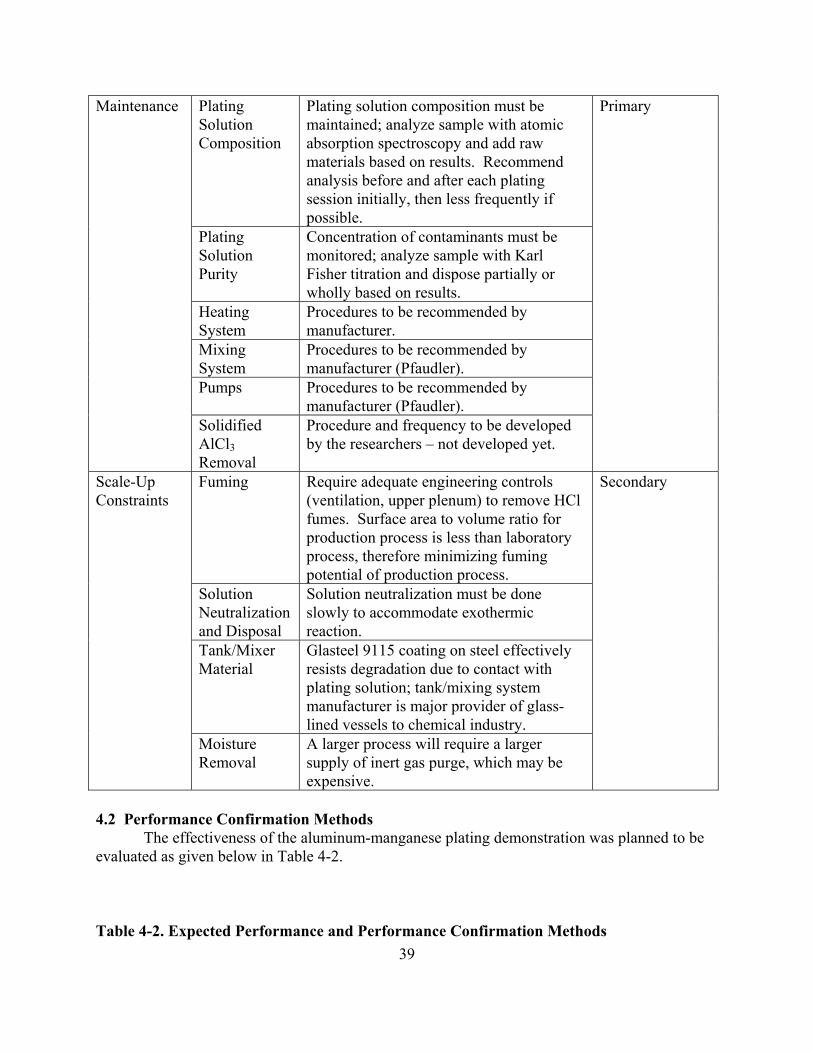
Plating Solution Composition
Plating solution composition must be maintained; analyze sample with atomic absorption spectroscopy and add raw materials based on results. Recommend analysis before and after each plating session initially, then less frequently if possible.
Plating Solution Purity
Concentration of contaminants must be monitored; analyze sample with Karl Fisher titration and dispose partially or wholly based on results.
Heating System
Procedures to be recommended by manufacturer.
Mixing System
Procedures to be recommended by manufacturer (Pfaudler).
Pumps Procedures to be recommended by manufacturer (Pfaudler).
Maintenance
Solidified AlCl3 Removal
Procedure and frequency to be developed by the researchers – not developed yet.
Primary
Fuming Require adequate engineering controls (ventilation, upper plenum) to remove HCl fumes. Surface area to volume ratio for production process is less than laboratory process, therefore minimizing fuming potential of production process.
Solution Neutralization and Disposal
Solution neutralization must be done slowly to accommodate exothermic reaction.
Tank/Mixer Material
Glasteel 9115 coating on steel effectively resists degradation due to contact with plating solution; tank/mixing system manufacturer is major provider of glass-lined vessels to chemical industry.
Scale-Up Constraints
Moisture Removal
A larger process will require a larger supply of inert gas purge, which may be expensive.
Secondary
4.2 Performance Confirmation Methods The effectiveness of the aluminum-manganese plating demonstration was planned to be evaluated as given below in Table 4-2. Table 4-2. Expected Performance and Performance Confirmation Methods
39

Performance Criteria
Expected Performance Metric (pre demo)
Performance Confirmation Method
Actual Performance (post demo)
PRIMARY CRITERIA (Performance Objectives) (Quantitative) Product Testing
Appearance Coating is continuous, smooth, adherent, uniform in appearance, free from blisters, pits, nodules, burning, contaminants, excessive powder, and other apparent defects that could reduce serviceability or protection.
AMS-QQ-P-416.
Coating thickness uniformity
Plating thickness remains within class when measured after plating. Composition of the coating must stay within the process range when measured using the X-ray Fluorescence Alloy Composition Uniformity Test.
AMS-QQ-P-416.
Alloy composition uniformity
Composition stays within the process specification requirements.
ASTM B568, ASTM E1621.
Repairability Repair performance meets or exceeds performance of experimental control specimens.
MIL-STD-865.
Unscribed salt spray corrosion resistance
Minimum of 3,000 hours exposure before appearance of red rust.
ASTM B117.
Scribed salt spray corrosion resistance
Minimum of 1,000 hours exposure before appearance of red rust.
ASTM B117.
Galvanic corrosion resistance
Alternative meets or exceeds cadmium in appearance and corrosion resistance.
ASTM B117.
Fluid corrosion resistance
No coating degradation greater than that of cadmium plated control specimens.
MIL-PRF-5624, MIL-H-6083, MIL-H-53282.
Bend adhesion No separation (flaking, peeling, or blistering) from the basis metal or from any underplating at the rupture edge. Cracking is acceptable in the bend area if the coating cannot be peeled back with a
ASTM B571.
40

sharp instrument. Water boil adhesion
No separation (flaking, peeling, or blistering) from the basis metal or from any underplating at the edge.
ASTM B571.
Wet tape paint adhesion
Adhesion not less than that of the cadmium coated control specimens when immersed for 24 hours at 23 degrees Celsius.
ASTM D3359, FED-STD-141, MIL-PRF-85582.
Run-on and breakaway torque
During installation, the maximum locking torque shall not exceed 30 in-lb. During removal, the minimum breakaway torque shall not be less than 3.5 in-lb. After 15 cycles locking torque test, nut and bolt threads shall remain in serviceable condition; when examined at 10x magnification, thread peel, missing segments, cracks, galling, or splits are unacceptable.
MIL-N-25027, NASM-1312-31.
Torque tension
Torque-tension for candidate material is within the range for cadmium plated fasteners. Fastener does not yield or fracture, threads do not strip.
MIL-N-25027, NASM-1312-15.
Sustained tensile load
No test specimen fracture within the 200 hour exposure time.
ASTM F519.
Rotating beam fatigue
Fatigue values to be comparable to cadmium plated coupons.
ASTM E468, ISO 1143.
Temperature limitations
Temperature limitation shall be suitable for the intended application.
Coating strippability
Candidate coating should be removed in two hours or less using appropriate removal method, such that the surface meets requirements of MIL-S-5002. Reapplied coating meets the Acceptance Criteria of Bend Adhesion. ASTM B571.
MIL-S-5002, ASTM B571.
Scribed SO2 salt spray corrosion resistance
No blistering or lifting of coating greater than control specimens. No substrate corrosion greater than control specimens.
ASTM D1654.
Scribed carrier exposure corrosion resistance
No blistering or lifting of coating. No excessive substrate corrosion after one carrier deployment (6 to 12 months).
ASTM D1654.
Tension–tension fatigue
Fatigue values to be comparable to cadmium plated coupons.
ASTM E4, ASTM E380, ASTM
41

E467. Hazardous Materials Reduce cadmium use
80-100 % less cadmium use is longterm goal.
Mass balance.
Reduce cyanide use
80-100 % less cyanide use is longterm goal.
Mass balance.
Aluminum chloride, manganese chloride, sodium hydroxide
Hazardous materials introduced by aluminum-manganese plating. Aluminum chloride is corrosive and reactive with water. Caustic sodium hydroxide will be used to neutralize spent plating solution.
Mass balance.
Process Waste Aluminum-manganese plating solution
Corrosive, reactive with water. May require disposal as hazardous waste; or, may treat in process and dispose as solid waste. Estimate 1,000 gallons or less to dispose per year (for 1,000-gallon plating tank).
Track waste disposal volume.
Rinse water Will contain aluminum and manganese oxides/hydroxides, sodium chloride, and potassium chloride in dilute hydrochloric acid solution. Will have low pH, and can be neutralized with sodium hydroxide solution. Estimate 10 gallons of rinse water to dispose per plating session.
Track waste disposal volume.
Factors Affecting Performance Solution Temperature
Temperature must be maintained within 5 degrees Celsius.
Temperature controller.
Solution Composition
Composition must maintain approx. 1% manganese.
Analyze sample with AA.
Solution Agitation
Solution must be agitated mildly throughout plating sessions.
Track mixer rpms.
Current Pulse Sequence
Proper pulse sequence required – to be determined individually for each component.
Pre-program power supply for each component.
PRIMARY CRITERIA (Performance Objectives) (Qualitative) Ease of Use Manpower One artisan skilled in electroplating will
be required to operate the process; several extra operators and engineers present for startup.
Operating experience.
Skill The artisan will need training specifically Operating
42

43
related to molten salt plating, including MSDS, PPE, and process procedures. Use of analytical laboratory will be required.
experience.
Monitoring Process must be monitored continuously during demonstration – power supply pulses, and solution temperature, composition and purity.
Operating experience, recordkeeping.
OSHA Training
OSHA health and safety training is recommended.
Recordkeeping.
Shift Aluminum-manganese may be operated either one shift per day or 24 hours per day.
Operating experience.
Maintenance Plating Solution Composition
Plating solution composition must be maintained; analyze sample with atomic absorption spectroscopy and add raw materials based on results. Recommend analysis before and after each plating session initially, then less frequently if possible.
Operating experience, recordkeeping.
Plating Solution Purity
Concentration of contaminants must be monitored; analyze sample with Karl Fisher titration and dispose partially or wholly based on results.
Operating experience, recordkeeping.
Heating System
Procedures to be recommended by manufacturer.
Operating experience.
Mixing System
Procedures to be recommended by manufacturer (Pfaudler).
Operating experience.
Pumps Procedures to be recommended by manufacturer (Pfaudler).
Operating experience.
Solidified AlCl3 Removal
Procedure and frequency to be developed by the researchers.
Operating experience.
SECONDARY PERFORMANCE CRITERIA (Qualitative) Reliability Mixer drive Potential to degrade with exposure to HCl
fumes. Will minimize exposure with ventilation and orientation of drive away from fume emitting sources.
Recordkeeping.
Other equipment
All other equipment can be adequately protected from HCl fumes by coating with corrosion protective epoxy paint, sheathing with silicone rubber or fluoropolymer, or constructing with
Recordkeeping.

Plexiglas/polymeric material. Equipment can be protected from exposure to plating solution by coating with Glasteel 9115.
Versatility Other applications
Equipment may be drained of aluminum-manganese plating solution and loaded with other plating solution easily.
Operating experience.
Other locations
Equipment may be installed at any location where ceiling height adequate and overhead crane or other automated transfer equipment available.
Operating experience.
Cadmium Replacement
Aluminum-manganese plating has potential to be one-for-one replacement for cadmium plating, except for temperature sensitive substrates. At this time temperature sensitive substrates cannot be aluminum-manganese plated due to high operating temperature requirement.
Operating experience.
Scale-Up Constraints Fuming Require adequate engineering controls
(ventilation, upper plenum) to remove HCl fumes. Surface area to volume ratio for production process is less than laboratory process, therefore minimizing fuming potential of production process.
Operating experience.
Solution Neutralization and Disposal
Solution neutralization must be done slowly to accommodate exothermic reaction.
Operating experience.
Tank/Mixer Material
Glasteel 9115 coating on steel effectively resists degradation due to contact with plating solution; tank/mixing system manufacturer is major provider of glass-lined vessels to chemical industry.
Operating experience.
Moisture Removal
A larger process will require a larger supply of inert gas purge, which may be expensive.
Operating experience.
4.2.1 Data Collection Initially, low strength steel test panels and scrap components were planned to be used for testing and evaluation. Test panels and components were planned to be evaluated by the depot Materials Lab in accordance with the tests outlined in JTP-BD-P-1-1. A detailed testing schedule was not developed prior to system shutdown.
4.2.2 Experimental Controls
44

Process log sheets were planned for the plating process and would have included analytical analysis of the salt bath, amp-minute energy consumption records, and coating characteristics, such as thickness and composition. Plating efficiency was planned to be tracked to observe process performance with time. 4.3 Data Analysis, Interpretation and Evaluation The functional performance of cadmium alternatives should be tested in accordance with JTP BD-P-1-1 “Validation of Alternatives to Electrodeposited Cadmium for Corrosion Protection and Threaded Part Lubricity Applications,” and “High Strength Steel Joint Test Protocol for Validation of Alternatives to Low Hydrogen Embrittlement Cadmium for High Strength Steel Landing Gear and Component Applications.” Both documents provide acceptance criteria for each performance area.
45

5. Implementation Issues
5.1 Environmental Permits Permit for air emissions - complete. •
•
•
Depot approval for release of rinse tank contents to on-site water treatment facility - complete. Depot approval for disposal of spent plating solution (hazardous waste) - complete.
5.2 Other Regulatory Issues Regulatory issues were addressed previously in this report. 5.3 End-User/Original Equipment Manufacturer (OEM) Issues Refer to Section 1.5 for discussion of end-user/OEM issues. End-users for this technology are found in the user (program managers), producer (depots & original equipment manufactures (OEM)), and approval authority (i.e., NAVAIR) communities. The primary end-user concern is demonstration that electroplating of aluminum-manganese is a commercially viable process, i.e., affordable, producible, and reliable. End-users require extensive testing and field evaluation before any technology is transitioned for use on aircraft components.
6. References 1. "Joint Test Protocol BD-P-1-1 for Validation of Alternatives to Electrodeposited Cadmium
for Corrosion Protection and Threaded Parts Lubricity Applications." Engineering and Technical Services for Joint Group on Pollution Prevention Projects, 30 June 1999.
2. “High Strength Steel Joint Test Protocol for Validation of Alternatives to Low Hydrogen Embrittlement Cadmium for High Strength Steel Landing Gear and Component Applications.” The Boeing Company Phantom Works and Concurrent Technologies Corporation, July 31, 2003.
46

7. Points of Contact
POINT OF CONTACT
Name
ORGANIZATION Name
Address
Phone/Fax/Email Role in Project
Erin Beck Naval Air Systems Command Research and Engineering Group 48066 Shaw Rd., Bldg. 2188 Patuxent River, MD 20670
Ph: 301-342-6183 Fax: 301-342-7566 Email: [email protected]
Project Manager, Principle Investigator
Jim Green Naval Air Systems Command Research and Engineering Group 48066 Shaw Rd., Bldg. 2188 Patuxent River, MD 20670
Ph: 301-757-2322 Fax: 301-342-7566 Email: [email protected]
Chemist, Plating Specialist
Steve Brown Naval Air Systems Command Research and Engineering Group 48066 Shaw Rd., Bldg. 2188 Patuxent River, MD 20670
Ph: 301-342-8101 Fax: 301-342-7566 Email: [email protected]
Materials Engineering
Cid Richards NAS North Island Code 61200, Bldg. 472 San Diego, CA 92135
Ph: 619-545-3171 Email: [email protected]
New Technologies Insertion, Industrial Engineering
Ed Duffy NAS North Island Code 43410, Bldg. 469 San Diego, CA 92135
Ph: 619-545-9760 Email: [email protected]
Materials Engineering
47

Appendix A
Appendix A Aluminum-Manganese Plating Standard Operating Procedure
________________________________________________________________________
DRAFT – SEPTEMBER 2005
Standard Operating Procedure (SOP) Aluminum-Manganese Molten Salt Plating
I. System Startup
1. COMPLETE “Daily Checklist while Running the Process”. 2. RINSE TANK #1
a. Remove and store tank covers. b. Ensure water level is at fill line. Add water if necessary. c. Turn on the tank circulation pump. Switch is mounted on north side of the tank.
3. RECTIFIER Facility Requirements:
a. 120 VAC @ 60 Hz with ground connection b. 440 VAC, 3 Phase, >45 amp, @60 Hz with ground connection c. Cooling water supply: tap water >40 PSI, >3 GPM, < 30oC d. IBM Compatible PC with “Starter” software, RS232/RS422 converter box and
cables
Operating Safety: a. Chemical Exposure – An eyewash/shower is provided at the work site in the event
of serious chemical exposure. b. Always use good electrical connections at the Rectifier and the work piece, as
high resistance connections may lead to overheating and fire. High amperage arcing can cause burns from molten/ionized metal explosions.
c. Never operate Rectifier without cooling water operational (valve open or pump energized) to prevent unit overheating.
d. When working at the top of the tank hood, ensure no loose items are allowed to fall into opening, including but not limited to items in shirt pockets, loose goggles/face shields, writing utensils, flashlights, etc.
e. All fixtures or others items to be lowered into the tank need to be inspected carefully for any loose or insufficient connections. Also, no hard or sharp surfaces should be exposed at the extremities such that they may damaged the Teflon lining of the hood/tank.
f. Do not immerse any components into the rinse tank (s) if ventilation system if malfunctioning.
g. Drips of nitric acid solution should be cleaned up with the spill neutralizer kit.
48

Appendix A
“Starter” Program Hints a. All entries are made using the mouse or pointing device b. All numbers are entered with the keypad on the screen and the mouse or pointing
device. c. All digits entered in a variable’s number range displace the previous digits to the
left as they are entered. Entering digits into a variable in which non-zero digits previously existed does not necessarily clear the number range. The old numbers are just moved to the left. Ensure that the number range contains only the desired digits prior to selecting Enter.
d. Once a variable is selected you must hit Enter or Cancel on the screen keypad to release control for another function to be selected.
e. Once a program screen is acceptable select Store to save the program.
Prior to Operating the Rectifier: a. Ensure the main breaker is ON for the 480V circuit powering the Rectifier.
Breaker box HT-1, CKT #1 on East wall and Disconnect box on East wall. b. Ensure that the Rectifier is plugged into 440 VAC power. c. Get laptop computer, power cord, and mouse from storage cabinet and take up to
rectifier. d. Ensure that the PC is plugged into 120 VAC power e. Ensure that the short cable connects the converter box (RS232 side) to the
computer (COM1) and the long one (RS422 side) to the rectifier. f. Plug in the rectifier cooling water pump submerged in the 55 gal drum to GFCI
receptacle (both lower level) and top off water level if required. g. Ensure the plating cables are tightly bolted onto the studs on the back of rectifier.
Operating the Rectifier
a. Turn on PC and start the “Starter” program (double-click on “Starter” icon on the desktop). NOTE: THE “STARTER” PROGRAM MUST BE RUNNING PRIOR TO ENERGIZING THE RECTIFIER IN ORDER FOR COMMUNICATIONS BETWEEN THE TWO TO BE ESTABLISHED.
b. At the opening screen of “Starter” click the Continue button. This opens the System Status Screen. The Fault indication will initially be RED until the rectifier is turned ON. The Fault indication will remain RED even after the rectifier is turned ON only if there is a problem (see Troubleshooting Tips).
c. Turn on the rectifier by flipping the circuit breaker up on the front of the rectifier (the front is to your left). When the breaker is turned ON the RED FAULT indicator should disappear.
d. If you know the Unit Recipe you want, click on the New Unit Program button. Proceed to step “f”.
e. If unsure of the Unit Recipe you want, click on the Return To Main Menu button and select Recipe List Status to browse available selections. Return to Main Menu and select Cycle Profile List Status to browse the selections used in a Unit Recipe. The cycle profile defined on the Cycle Profile screen can be viewed by selecting the Graph button. This opens the Cycle Profile Graph screen. Selecting
49

Appendix A
Amps on this screen display the graph of the Current Reference Cycle Profile (the Y-axis is scaled as a percentage of the current set value). Selecting Volts on this screen display the graph of the Voltage Reference Cycle Profile (the Y-axis is scaled as a percentage of the voltage set value). If a new Unit Recipe and/or Cycle Profile is required it can be programmed (see Programming the Rectifier).
f. At the New Unit Program screen select Unit Address and enter the two digit address (01, 02, 03, etc. + Enter). If the current stored Unit Recipe is not the desired one select Unit Recipe and enter the two digit Unit Recipe number to be run, select Enter, select Store and answer Yes to delete previous Unit Recipe. Select System Status Screen and verify that the new recipe was stored for the unit. Select Return to Main Menu.
g. At the Main Menu select Command Menu. At the Command Menu select Select Unit Address and enter the two digit address (01, 02, 03, etc. + Enter). The Start button should now be highlighted.
h. When ready to plate/anodize, select Start. Start button will “gray out” and the Stop and Pause buttons will be highlighted.
i. To verify unit operation select Return To Main Menu. At the Main Menu screen select System Status Screen. At the System Status Screen the DC ON indication will be filled in when the unit is running. For monitoring the rectifier during operation select the Unit Address button corresponding to the desired unit. This will bring up the Unit Status Screen for the desired unit. Note the button for Fault History on this screen.
j. Unit control (Stop, Start, Pause, and Continue) can only be accomplished from the Command Menu.
4. VENTILATION
a. Set valve positions as follows: i. Place round lid on top of plating tank hood.
ii. Duct #20 OPEN. (valve located on lower level near east side of plating tank)
iii. Duct #30 CLOSED. (valve located on lower level near east side of plating tank)
iv. Rinse Tank #1 blanking plate should be installed and set to “LOW” position (only part of bottom slot is left uncovered).
b. Ensure power to ventilation is ON. Breaker box HT-1 on East wall, CKT #7. c. Turn on ventilation by pressing green ON button. Box located on East wall.
CAUTION: If ventilation does not turn on or proper valve position cannot be achieved do NOT proceed with processing. Seek facilities or engineering assistance.
NOTE: If round lid on top of plating tank hood chatters then rotate it until chatter stops.
5. NITRIC ACID ETCH TANK a. Put on the following PPE: chemical resistant gloves, goggles, rubber apron.
50

Appendix A
b. Turn on the water to the spray wand at Rinse Tank #2 and set the spray nozzle to “mist”.
c. Connect the air gun hose to shop air. d. Remove lid from acid tank and rinse acid condensation off inside of lid with fresh
water mist over Rinse Tank #2. Set lid aside. e. Check that fluid level is at fill line. If fluid level below fill line then add water to
fill line. (Note: Fill line is 6” below the top of the tank.) f. Place lid back on tank.
II. Cathode Fixture Preparation (first run of the day only)
1. Hang fixture from overhead crane hook and locate fixture over the closed acid tank. 2. Ventilation
a. Set valve positions as follows (same as Section I.4.a.): i. Place round lid on top of plating tank hood.
ii. Duct #20 OPEN. (valve located on lower level near east side of plating tank)
iii. Duct #30 CLOSED. (valve located on lower level near east side of plating tank)
iv. Rinse Tank #1 blanking plate should be installed and set to “LOW” position (only part of bottom slot is left uncovered).
b. Ensure power to ventilation is ON. Breaker box HT-1 on East wall, CKT #7. c. Turn on ventilation by pressing green ON button. Box located on East wall.
CAUTION
If ventilation does not turn on or proper valve position cannot be achieved do NOT proceed with processing. Seek facilities or engineering assistance.
3. Put on the following PPE: chemical resistant gloves, goggles, rubber apron. 4. Turn on the water to the spray wand at Rinse Tank #2 and set the spray nozzle to “mist”. 5. Connect the air gun hose to shop air. 6. If the fixture is dirty/greasy then acetone wipe the fixture. 7. Remove lid from acid tank. Rinse acid condensation off inside of lid with fresh water
mist over Rinse Tank #2 if the lid has not been rinsed within the last 24 hours. Set lid aside.
8. Using overhead crane lower fixture into Nitric Acid Etch Tank until the acid level is a couple inches below the Teflon disc on the fixture. Press DOWN button fully to lower most quickly. Immerse for 60 to 90 seconds. ETCH RATE DETERMINATION: Observe the color change in aluminum – it should lighten - to determine effectiveness of etch. If the fixture is insufficiently etched (cleaned) of the dark film then re-immerse. If longer than 2 minutes is required then the solution should be analyzed and adjusted.
9. Lift fixture up out of Nitric Acid Etch Tank. Press UP button fully to raise most quickly. Allow most drips to subside.
51

Appendix A
10. Position the fixture over Rinse Tank #2 near to the North end of the tank. Move the fixture slowly to minimize fixture swing. Note: Drips of Acid solution during the transportation of the fixture to tank #2 should be treated with neutralizer from the spill cleanup kit.
11. Gently rinse the fixture with the water spray wand in “mist” mode, trying to capture runoff in Rinse Tank #2. Try not to get stairs wet with overspray.
12. Dry fixture thoroughly with the air gun. Be especially careful to dry water out of crevices. Note: water is a contaminant to the plating process and will trigger a dangerous reaction if introduced in large quantity into the plating tank.
13. Place lid back on acid etch tank. 14. Hang fixture on the Storage Hook until needed.
III. Anode Fixture Preparation
1. Inspect Teflon taped areas and repair if necessary. 2. Hang fixture from overhead crane hook and position the fixture over the closed acid tank.
(Will need to remove the top stainless steel rod, clasp the remaining rod with the crane hook, replace the rod that was removed by threading it through the crane hook, and finally lift the fixture off its storage hook. The cotter pin holes in the rods are off center and allow for easier on/off of pins on one side)
3. Ventilation a. Set valve positions as follows (same as Section I.4.a.):
i. Place round lid on top of plating tank hood. ii. Duct #20 OPEN. (valve located on lower level near east side of plating
tank) iii. Duct #30 CLOSED. (valve located on lower level near east side of plating
tank) iv. Rinse Tank #1 blanking plate should be installed and set to “LOW”
position (only part of bottom slot is left uncovered). b. Ensure power to ventilation is ON. Breaker box HT-1 on East wall, CKT #7. c. Turn on ventilation by pressing green ON button. Box located on East wall.
CAUTION If ventilation does not turn on or proper valve position cannot be achieved do NOT proceed with processing. Seek facilities or engineering assistance.
4. Put on the following PPE: chemical resistant gloves, goggles, rubber apron. 5. Turn on the water to the spray wand at Rinse Tank #2 and set the spray nozzle to “mist”. 6. Connect the air gun hose to shop air. 7. If the fixture is dirty/greasy then acetone wipe the fixture. 8. Remove lid from acid tank. Rinse acid condensation off inside of lid with fresh water
mist over Rinse Tank #2 if the lid has not been rinsed within the last 24 hours. Set lid aside.
9. Using overhead crane lower fixture into Nitric Acid Etch Tank until the acid level is about 2 feet below the beveled ring on the fixture. Press DOWN button fully to lower
52
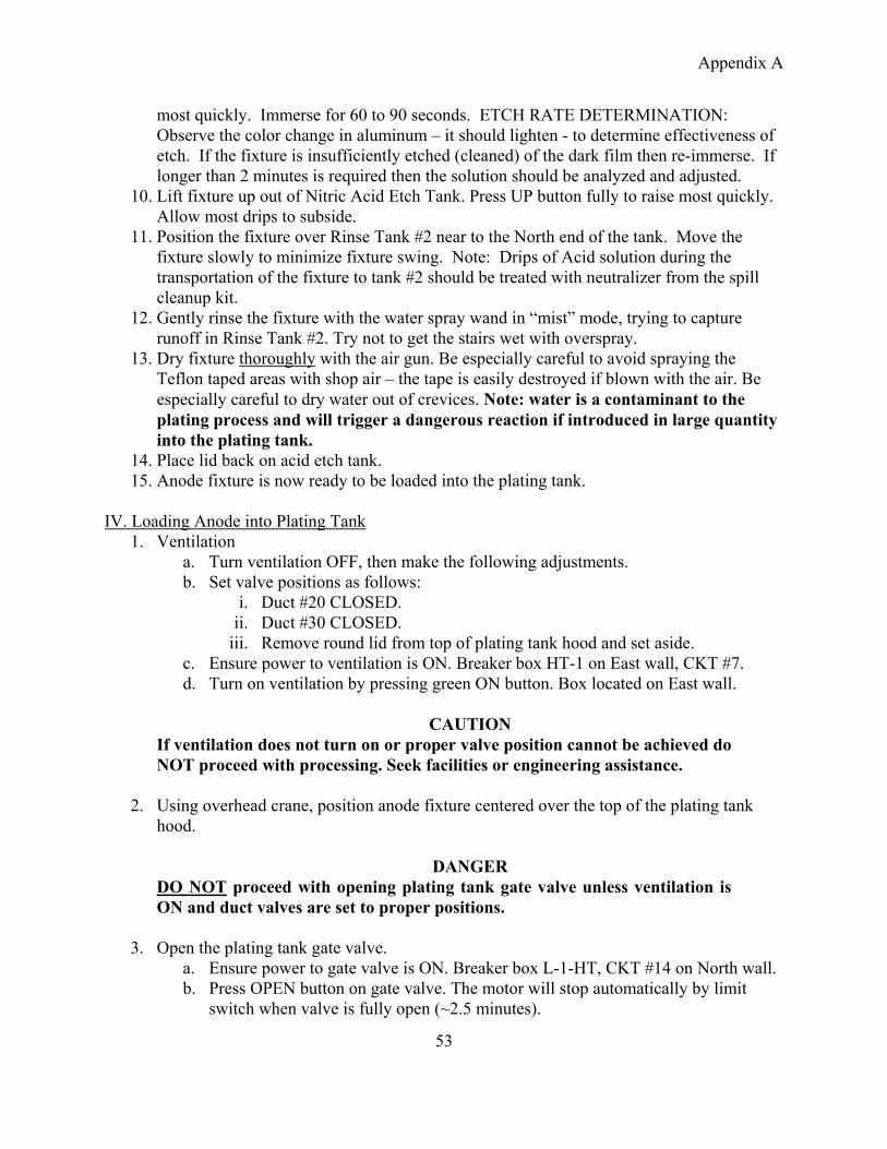
Appendix A
most quickly. Immerse for 60 to 90 seconds. ETCH RATE DETERMINATION: Observe the color change in aluminum – it should lighten - to determine effectiveness of etch. If the fixture is insufficiently etched (cleaned) of the dark film then re-immerse. If longer than 2 minutes is required then the solution should be analyzed and adjusted.
10. Lift fixture up out of Nitric Acid Etch Tank. Press UP button fully to raise most quickly. Allow most drips to subside.
11. Position the fixture over Rinse Tank #2 near to the North end of the tank. Move the fixture slowly to minimize fixture swing. Note: Drips of Acid solution during the transportation of the fixture to tank #2 should be treated with neutralizer from the spill cleanup kit.
12. Gently rinse the fixture with the water spray wand in “mist” mode, trying to capture runoff in Rinse Tank #2. Try not to get the stairs wet with overspray.
13. Dry fixture thoroughly with the air gun. Be especially careful to avoid spraying the Teflon taped areas with shop air – the tape is easily destroyed if blown with the air. Be especially careful to dry water out of crevices. Note: water is a contaminant to the plating process and will trigger a dangerous reaction if introduced in large quantity into the plating tank.
14. Place lid back on acid etch tank. 15. Anode fixture is now ready to be loaded into the plating tank.
IV. Loading Anode into Plating Tank
1. Ventilation a. Turn ventilation OFF, then make the following adjustments. b. Set valve positions as follows:
i. Duct #20 CLOSED. ii. Duct #30 CLOSED.
iii. Remove round lid from top of plating tank hood and set aside. c. Ensure power to ventilation is ON. Breaker box HT-1 on East wall, CKT #7. d. Turn on ventilation by pressing green ON button. Box located on East wall.
CAUTION If ventilation does not turn on or proper valve position cannot be achieved do NOT proceed with processing. Seek facilities or engineering assistance.
2. Using overhead crane, position anode fixture centered over the top of the plating tank hood.
DANGER
DO NOT proceed with opening plating tank gate valve unless ventilation is ON and duct valves are set to proper positions.
3. Open the plating tank gate valve.
a. Ensure power to gate valve is ON. Breaker box L-1-HT, CKT #14 on North wall. b. Press OPEN button on gate valve. The motor will stop automatically by limit
switch when valve is fully open (~2.5 minutes).
53

Appendix A
c. Listen for motor’s pitch to change for 3 to 5 seconds without stopping, then press STOP button if the motor does not stop by itself (in case of auto stop malfunction).
d. Verify gate valve is fully open by comparing location of shaft cylinder to marks on gear body.
DANGER
If fumes are emitted from plating tank hood quickly press STOP button, then the CLOSE button and leave the area immediately. Report situation to depot Engineering and Safety Offices immediately.
4. Put on the following PPE: chemical resistant gloves, safety glasses or goggles, rubber
apron. 5. Immediately after the gate valve is fully open slowly lower the anode fixture down into
the plating tank. 6. Unhook the anode fixture from the crane. 7. Lower the dummy lid by hand down through the plating tank hood so that it rests on and
blocks the opening in the anode fixture. The purpose of the dummy lid is to prevent excessive escape of plating bath fumes through the ventilation system.
8. Lightly clean anode and anode cable (red “+”) electrical contact surfaces with dry abrasive pads (ensure pads used on aluminum only) to achieve clean, bright surface. Green Scotchbrite pads work well.
9. Apply a light film of Oxyguard conductive lubricant (or similar antioxidant conductive compound) to contact surfaces.
10. Mate anode cable with bolt or clamp to anode fixture. 11. Wipe off excess Oxyguard lubricant.
V. Component/Part Preparation
1. Lift cathode fixture up from its Storage Hook until the bottom of the fixture is at eye level.
2. At the bottom of the fixture ensure the electrical contact surfaces are clean and oxide-free. Use dry abrasive pads to clean if necessary. High resistance connections may lead to overheating and arcing.
3. Degrease, grit blast, mechanically mask part to be plated as required per NADEP Work Instructions. Teflon tape is currently the only approved maskant for this plating process and takes precedence over NADEP Work Instructions.
Grit Blaster Operation a. Turn on ventilator b. OPEN shop air valve on wall behind blast cabinet. c. Verify pressure at 60 psig using regulator. d. Turn on light with switch on left side of cabinet. e. Add aluminum oxide media (60 grit) if required. Bottom hopper should be
MAXIMUM 1/3 full. f. If gun spits water during operation check water trap.
54

Appendix A
g. Blast part to uniform clean finish. Do not open side door until the air has cleared.
h. CLOSE shop air valve and turn off light when finished. 4. Attach part securely at bottom of fixture. 5. Put on the following PPE: chemical resistant gloves, safety glasses or goggles, rubber
apron. 6. Using overhead crane position cathode fixture centered over the top of the plating
tank hood. 7. Lift the dummy lid up out of the plating tank hood and allow the lid to idle in the
hood until fuming subsides (approx. 2-3 minutes). Lift the dummy lid completely out of the plating tank hood and submerge the lid in Rinse Tank #1. The lid should remain in the rinse tank until fuming has subsided and no visible residual plating solution remains on the lid. Once the lid is clean (all residue has dissolved off the lid) remove the lid from the rinse tank, wipe it dry and set the lid aside.
8. Immediately lower the cathode fixture into the plating tank hood, ensuring the fixture does not scratch the Teflon-coated surfaces of the hood. Continue lowering until the fixture seats and self-centers on beveled ring of the anode fixture.
9. Unhook the cathode fixture from the crane. 10. At the top of the fixture lightly clean cathode and cathode cable (black “-“ electrical
contact surfaces with dry abrasive pads (ensure pads used on aluminum only) to achieve clean, bright surface.
11. Apply a light film of Oxyguard conductive lubricant (or similar antioxidant conductive compound) to contact surfaces.
12. Mate cathode cable with bolt or clamp to cathode fixture. 13. Wipe off excess Oxyguard lubricant. 14. Immediately initiate plating process by clicking the Start icon on the Rectifier laptop.
VI. Plating and Rinsing
1. Initiate plating as soon as the part is situated in the plating tank by clicking the Start icon on the Rectifier laptop.
2. Refer to Section I, Paragraph 3 RECTIFIER for detailed instructions on using the plating computer program to process parts.
3. Put on the following PPE: chemical resistant gloves, safety glasses or goggles, rubber apron.
4. Immediately after plating cycle is completed remove cable from cathode, hook overhead crane to cathode fixture and lift cathode fixture up into the plating tank hood. Allow the cathode fixture to remain inside the Plating Tank Hood until plating solution drag-out stops fuming and forms a solid crust on the fixture (up to about 5 minutes). Once fuming has subsided lift cathode fixture up out of the hood.
5. Position the cathode fixture over Rinse Tank #1. CAUTION: Do not immerse components with residual plating bath into the rinse tank if ventilation is malfunctioning. Completely immerse the fixture into the rinse tank as quickly as possible. Allow the fixture to remain submerged in the rinse water until all visible solution drag-out is dissolved off of the fixture and part. Time TBD.
55

Appendix A
CAUTION Hydrochloric acid fumes will be generated during the rinse step. Personnel should stand clear of the fumes which will be captured by the rinse tank ventilation.
6. As soon as cathode fixture is in Rinse Tank #1 lower the DRY dummy lid down into
plating tank hood by hand so that the lid rests on top of the anode fixture and prevents excessive escape of plating bath fumes through the ventilation system.
7. Raise cathode fixture up, leaving the plated part submerged in the water but accessible. Remove maskant from the part while the part is submerged in water. Plating solution that is trapped in masking can liberate hydrochloric acid fumes.
8. Re-immerse as much of the fixture as necessary to remove residual plating solution. 9. Once no visible plating solution drag-out remains on the fixture or part lift the fixture up
out of Rinse Tank #1. 10. Using the overhead crane position the fixture over Rinse Tank #2 near the North end of
the tank. 11. Gently rinse the fixture and part with the water spray wand in “mist” mode, trying to
capture runoff in Rinse Tank #2. Try not to get the stairs wet with overspray. 12. Dry fixture thoroughly with the air gun. Be especially careful to dry water out of
crevices. 13. Carefully remove part from fixture. If residual plating solution is present at attachments
points then spray those points with water until the residual plating solution is removed. Use shop air to dry any remaining wetted areas (especially attachment points).
14. Transport part for standard post-plate bake (within 4 hours of plating) and conversion coating per NADEP Work Instructions.
15. Wrap plated test coupons in acid free paper and place in plastic Ziploc bags. 16. Place fixture on Storage Hook.
VII. System Shutdown Procedure
1. Put on the following PPE: chemical resistant gloves, safety glasses or goggles, rubber apron.
2. Anode fixture a. Lift the dummy lid up out of the plating tank hood and allow the lid to idle in the
hood until fuming subsides (approx. 2-3 minutes). Lift the dummy lid completely out of the plating tank hood and submerge the lid in Rinse Tank #1. The lid should remain in the rinse tank until fuming has subsided and no visible residual plating solution remains on the lid. Once the lid is clean (all residue has dissolved off the lid) remove the lid from the rinse tank, wipe it dry and set the lid aside.
b. Lift anode fixture up into the plating tank hood. Allow the fixture to remain inside the hood until plating solution drag-out stops fuming and forms a solid crust on the fixture (up to about 5 minutes). Once fuming has subsided lift the fixture up out of the hood.
56

Appendix A
c. Position the fixture over Rinse Tank #1. Completely immerse the fixture into the rinse tank as quickly as possible. Allow the fixture to remain submerged in the rinse water until all visible solution drag-out is dissolved off of the fixture. Time TBD.
CAUTION
Hydrochloric acid fumes will be generated during the rinse step. Personnel should stand clear of the fumes which will be captured by the rinse tank ventilation.
d. As soon as the fixture is in the rinse tank CLOSE the plating tank gate valve to
prevent excessive escape of plating bath fumes through the ventilation system. i. Press CLOSE button. After about 2.5 minutes ensure the valve has closed
fully. If the motor does not stop at the limit switch (motor pitch change) then press STOP manually.
e. Place round lid on top of plating tank hood. f. Once no visible plating solution drag-out remains on the fixture lift the fixture up out
of the rinse tank. g. Using the overhead crane gently position the fixture over Rinse Tank #2 near the
North end of the tank. h. Gently rinse the fixture with the water spray wand in “mist” mode, trying to capture
runoff in Rinse Tank #2. Try not to get the stairs wet with overspray. i. Dry fixture thoroughly with the air gun. Be especially careful to avoid spraying the
Teflon taped areas with shop air – the tape is easily destroyed if blown with the air. Be especially careful to dry water out of crevices.
j. Place fixture on Storage Hook. 3. Rinse Tank #1
a. Ensure pH is within target range. Turn controller off of RUN mode to avoid inadvertent chemical additions during downtime. If the controller is unplugged then unhook the BNC connector from the controller. The pH probe can become damaged if the BNC connector is connected to the controller while the controller is unpowered.
b. Top off water level if low. c. Turn OFF tank circulation pump using the rocker switch adjacent to the chemical
feed controller. d. Place cover on tank.
4. Plating Computer - Exit plating computer program. Shutdown and secure computer. 5. Plating Rectifier - Turn OFF breaker on front of rectifier. 6. Ensure plating tank hood gate valve is closed.
a. Turn breaker OFF. Breaker box L-1-HT, CKT #14 on North wall. 7. Leave plating tank impeller on and set at operating speed. 8. Plating tank heater
a. Decrease heater set point no lower than 220°F if desired for nights/weekends (Keep in mind that heat up time is approx. 1°F per 5 minutes)
9. Shut down blast cabinet a. CLOSE compressed air valve on wall. b. Periodically inspect air hoses, nozzle and suction tube for excessive wear.
57

Appendix A
10. Turn off water to spray wand and unhook shop air to air gun used at Rinse Tank #2. At the end of a week-long run (frequency TBD) measure plating bath level, get a plating bath sample and take to Materials lab – Day 1. The lab should be able to analyze sample and report results by mid Day 2. Based on lab results make necessary chemical adds to the plating bath Day 2. The plating bath should be ready to plate again early Day 3. VIII. Obtaining a sample of plating solution
1. Measure plating solution level using the aluminum “dipstick”. Restore level to Normal Operating Level before sampling to get an accurate volume baseline.
2. Lower the sampling cup into the plating solution using the aluminum extension rod provided. Raise the cup a use glass dropper to transfer some solution to a pre-weighed glass sample vial. Screw the top on the glass vial (must have a green Teflon lid).
3. Send for analysis; provide tare weight of container to chemist. IX. Making chemical adds to plating tank based on bath analysis
1. Using overhead crane center funnel over the top of the plating tank hood. 2. Lower the funnel into the hood until an approximately 6” gap remains between outer
surface of funnel and top of hood (do not rest funnel on top of hood). 3. Ramp the impeller speed up to the predetermined speed to be used when making
chemical additions, to ensure proper dispersion and avoid any potential “cold spots” on the glass surface.
4. Add aluminum chloride powders first. Use PPE: ________Carefully empty the container into the chemical addition chute.
5. Weigh and add granular salts next. Carefully pour the chemicals into the funnel. Ensure the manganese salt remains anhydrous (keep in oven at the lab if possible).
6. After all adds are made, verify that tank volume is up to the normal operating level using the pre-calibrated aluminum rod.
7. Allow at least 15 minutes for full chemical dissolution. 8. Increase the impeller speed slightly {TBD}for ~10 minutes to dissolve any waterline
crust that may have formed during the chemical addition process. 9. Update logsheet for chemicals added to the plating tank. 10. Ramp down the impeller speed to the overnight setting (______ rpm).
1. X. Plating Tank Draining Procedure Verify correct drain temperature if one has been established below normal process temperature.
2. Impeller – slowly ramp down speed to zero and turn off breaker to prevent accidental startup.
3. Check valve positions and configurations: a. #40 and #50 closed b. Place shoebox cover on top of plating tank hood c. #20 & #30 open (flexible ventilation hose). Move the flexible ventilation
piping from the acid tank (#20) to the drain station for supplemental ventilation during draining.
58

Appendix A
4. Plug in the Mettler-Toledo scale, and zero it out (tare) using the _0_ button on the front. Cover the scale with insulation pads to protect the sensors from the heat of the spent plating solution.
5. Prepare five (5) drums that will be used to contain the spent plating solution. Ensure the top covers are securely fastened. Position two 55gal drums on the scale in the pit manually or using the drum hoister.
a. Place the drum hoister onto a 55 gal. drum. Attach crane hook onto hoister mechanism. Raise crane to lift drum.
b. Leave/remove the drum hoister attached to the drum if possible c. Position the 4 inch diameter flexible vent hose over the smaller of the two
openings, make sure the valve to this leg of ventilation tubing is open and ventilation breaker is ON.
6. Bolt the flanged Teflon-coated drain hose to the vessel’s bottom drain valve a. Use a Teflon gasket between the drain hose and the bottom valve b. Position the drain hose into one of the drums. There should be a steel elbow
and reducer fitting at the end (reduces to 1” diameter opening) c. Make sure the drain hose can swing easily to the opening of the second drum;
adjust drum position if necessary 7. Conduct a Safety Briefing for all personnel involved with the drain, focusing on spill
handling procedures, personal protective equipment and special hazards associated with this solution.
8. Unlock the ball valve (on I-beam ____) used to pressurize the bottom drain lever-arm. The key to this valve shall be secured at all times, or a combination lock shall be used. CAUTION: If chemical adds or crust has entered the plating solution within the previous hour, it is best to allow 1 hour before attempting a drain due to possible obstruction of bottom valve, and potential loss of entire plating solution contents.
a. Verify the pressure is regulated to 80 psig (60-100 psig is operating range) on the regulator adjacent to the ball valve. Adjust if necessary.
9. Personnel shall wear appropriate PPE, i.e. goggles, face shields, aprons, and long gloves when draining the plating solution. Verify proper operation of the safety shower & eyewash.
10. Begin draining the vessel by slowly opening the air supply ball valve. CAUTION: DO NOT LEAVE THE DRAIN STATION while the bottom valve is open. Watch the drain valve lever-arm assembly as it shifts into the open position, then carefully watch the scale readout to determine weight of solution drained.
a. Stop draining when the 1st drum contains 45-50 liquid gallons (~ 700lbs), let the drain valve close and drain hose to completely empty. Better to be on the low side than risk a spill on the scale. Note: Quickly jog air valve if drain flow doesn’t stop entirely due to foreign matter preventing full closure of bottom valve.
b. Transfer the drain hose to the 2nd drum keeping it in an elevated position to prevent any spillage.
c. Transfer the ventilation piping to the 2nd drum. d. Fill the second drum
59

Appendix A
e. Cap both openings on each drum cover using the metal screw tops provided f. Remove the ventilation pipe from the drum
11. Hoist the drums of solution off the scale using the drum lifter and position them at the end of the pit where they can cool. (Later they will be placed in the yellow over packs for disposal).
12. Hoist two more drums on the scale, and drain the remaining solution as outlined in step 10.
13. When solution has cooled to ambient temperature (solidified), place waste drums in the yellow secondary containment drums and fasten the tops.
14. Clean the Teflon drain hose thoroughly by immersion in Rinse Tank #1, then spray clean over Rinse Tank #2.
XI. Empty Plating Bath Loading Procedures
1. Verify operation and condition of the vessel a. Heating function tested to 100 C (212 F) using water b. Use controlled heating rates such that excessive gradients are not experienced
by the tank wall (refer to all applicable Pfaudler manuals) c. Record all thermocouple temperatures during the heat up process, examples
shown below. Determine what heating profile will heat the tank as quickly as possible without exceeding design gradients.
Temperatures / Differentials Heater sheath (S) Bath contents
(B) Delta (S-B), Max=100
External TC
150 75 =150 - 75 100 d. Ensure tank is empty and dry before loading molten salt charge
2. Making “bricks” of Al-Mn plating bath salt a. Set fabricated hood on rinse tank #1 (rinse tank empty) b. Setup two hot plate stations with 4L Pyrex beakers, insulated c. Prepare aluminum mold bucket and charging bucket d. Prepare two batches of Al-Mn molten salt e. Pour the molten salt into the Al mold bucket f. Let the brick cool until it has just solidified g. Invert the bucket over a Teflon sheet; heat with propane torches to “release”
the brick h. Allow molten salt brick surfaces to solidify i. Place molten salt brick into the loading bucket
3. Loading Al-Mn bricks into vessel a. Attach chains from loading bucket onto the crane b. Hoist bucket over plenum c. Slowly lower into the tank d. When the bucket is very close to the tank floor, slowly tip the bucket using the
pull cord
XII. Plating Process Maintenance Procedures
60

Appendix A
1. The following items are important maintenance related concerns for glass lined vessels which are described more fully in the Pfaudler publication, “Installation and Maintenance of Glasteel Vessels, Instruction Manual IM81100-13” in the section and page number indicated. Table I below is provided below as a guideline for recommended frequency of preventative maintenance operations. Bolt torque procedures and sequences are discussed in Section 5.3 (pg. 36). Hand tightening followed by tightening in 20 ft-lb increments is recommended.
2. Inspect gasketed joints at regular intervals. 3. Gasket replacements may require shimming as described in Sec. 4 (pg. 33). 4. Inspection of glass lining.
a. Complete inspection recommended every 6 months. b. Glass integrity spark testing shall be conducted at periodic intervals c. Glass thickness tests can be performed to monitor service life of vessel.
5. Cleaning the vessel is covered in Sec. 3.3 (pg. 30) a. Protect the top of the vessel especially, and keep clean of corrosives so that
tank steel is not attacked. A shield or apron should be installed if the insulation does not provide full coverage.
6. Ventilation system maintenance – after any maintenance on the ventilation system, verify the directionality of air flow
Table. I. Recommended Maintenance Schedule for Al-Mn Process Daily Weekly Monthly 3 month 6 month 12 month
GLASS-LINED TANK
Inspect Tank for Acid drips X Inspect gasketed joints X Add / Change seal oil (Add) (TBD) Check bolt torques Initial
X
Inspect glass lining (Pfaudler) X Recalibrate / dead weight check scale
X
RINSE TANK #1
Check pH X Check caustic line and PVC circulation piping for leaks
X
Verify pH at laboratory X Measure conductivity X Replace rinse tank water (TBD) Replace caustic drum / empty (TBD) Eyewash check X
61

Appendix A
Add spill plan procedures
62

Appendix A
SOP APPENDIX: Rectifier Operation
Programming the Rectifier a. Rectifier programs are called Recipes. Recipe programs control the timing and
sequencing of sub-programs called Cycle Profiles. Cycle Profiles control direction, magnitude, and timing of the Rectifier’s electrical current and voltage.
b. Existing recipes can be reviewed by selecting Recipe List Status from the Main Menu screen. Existing cycle profiles can be reviewed by selecting Cycle Profile List Status. A cycle profile may be incorporated into many recipes and used more than once in a recipe.
REMEMBER the Rectifier ratings when programming cycle profiles:
• Pulsed & DC mode voltage: 12 VDC forward or reverse • DC mode amperage: 1,000 amps forward or reverse
• Pulsed mode amperage: 1,000 amps forward; 3,000 amps reverse NOTE: REVERSE TIME SHOULD BE SET TO LESS THAN 10% OF THE CYCLE TIME IF THE REVERSE AMPLITUDE IS SET TO OVER 1000A.
• Pulsed mode cycle profile segment time: 0.50 ms to 200.00 ms
Programming A New Cycle Profile a. To create a new cycle profile select New Cycle Profile Program from the Main
Menu screen. Select Cycle Profile Number and enter the desired number from the screen keypad + ENTER. An unused number may be selected for creating the new cycle profile or an existing cycle profile can be modified/overwritten.
b. The amps and volts in the segments on this screen are stored as percentages of the Set Amps and Set Volts values on the right side of the screen. Therefore, these values must be entered prior to programming the segments of the new cycle profile. If changed after segments have been programmed, all respective values will change in each segment previously programmed. Select Set Amps and enter the desired ceiling amps value for the cycle profile from the screen keypad + ENTER. Select Set Volts and enter the desired ceiling volts value for the cycle profile from the screen keypad + ENTER.
c. Pick the segment to program/modify. Selecting Forward will change it to Reverse. Selecting Reverse will change it to Forward.
d. Select Amps by clicking on the value box. Enter the desired amps on the screen keypad + ENTER.
e. Select Volts by clicking on the value box. Enter the desired volts on the screen keypad + ENTER.
f. Select Milliseconds by clicking on the value box. Enter the desired millisecond value on the screen keypad + ENTER. If only one segment is specified in the New Cycle Profile screen (any value from 0.50 ms to 200.00 ms can be entered in the Millisecond value box), the unit will operate in a DC mode (forward or reverse).
g. Repeat steps 3 through 6 until the desired cycle profile has been created.
63

Appendix A
h. Save the new cycle profile by selecting the Store button on the screen. If modifying/overwriting an existing program a warning screen will appear asking if you want to delete the old program. Answering Yes will save the new cycle profile.
Programming A New Recipe Program
a. To create a new recipe program select New Recipe Program from the Main Menu screen. Select Recipe Number and enter the desired number from the screen keypad + ENTER. An unused number may be selected for creating the new recipe or an existing recipe can be modified/overwritten.
b. Select the recipe period value box to program/modify and enter the desired value on the screen keypad + ENTER. Repeat for each recipe period needed.
c. Save the new recipe by selecting the Store button on the screen. If modifying/overwriting an existing program a warning screen will appear asking if you want to delete the old program. Answering Yes will save the new recipe.
Troubleshooting Tips
a. If communication between the “Starter” program and the Rectifier is lost during normal operation, the unit shuts off in 10 seconds.
b. If communication is interrupted, it might be necessary to re-cycle the power to the unit in order to restore the communication.
c. The loss of communication is indicated in the System Status Screen with a re fault light and the Off Line text in the Unit Status Screen. This is also recorded in the Fault History Screen.
d. If the “Starter” program locks up, restart the PC.
64

Appendix B
Appendix B Aluminum-Manganese Plating Mock Startup Procedure
DEPARTMENT OF THE NAVY RESEARCH AND ENGINEERING GROUP
NAVAL AIR DEPOT NORTH ISLAND PO BOX 357058
SAN DIEGO, CALIFORNIA 92135-7058
43410/ERD:tmh April 2005 Page 1 of 14
TITLE: Local Process Specification (LPS)
IDENTIFICATION: LPS NI MATL-0262 SUBJECT: MOLTEN SALT PLATING OF ALUMINUM-MANGANESE COATINGS ON STEEL
PARTS REFERENCE: (a) M. J. Kane et al., “Evaluation of Aluminum-Manganese as a Cadmium Replacement”,
NAWCAD (b) LPS NI MATL-0295, Baking for Hydrogen Embrittlement Relief for High Strength
Steel (160,000 psi and above) (c) LPS NI MATL-0253, Chemical Conversion Coating Aluminum and its Alloys
(d) Al-Mn Plating Bath Analysis Procedure, NAWCAD
(e) Rapid Pulse Reverse Switch Mode Power Supply Operation, NAWCAD
ENCLOSURE: (1) Aluminum Manganese Plating SetupDiagrams
65

Appendix B
1. PURPOSE: This specification is a summary of a new process that has been tested at NAWCAD Patuxent River and is now ready for demonstration/validation at the depot level. This draft has been produced to provide background information for health and safety recommendations at this command.
CANCELLATION: NA. 2.
BACKGROUND INFORMATION 3.
3.1 This coating is intended to replace cadmium on steel parts. Compliance with environmental, safety and health regulations and the potential legal liabilities for the continued in-service use, removal and disposal of cadmium coatings make the continued use of cadmium coatings expensive. Aluminum-manganese (Al-Mn) combines the advantages of Ion Vapor Deposition (IVD) aluminum and electroplating. Unlike IVD, molten salt plating of Al-Mn is not limited to line-of-sight, allowing coating of internal bores and threads. Compared to zinc-based coatings, which are also being considered as a replacement for cadmium, the electrochemical combination of an aluminum-based coating and iron in steel provides a greater resistance to environmentally assisted cracking (sometimes called stress corrosion cracking) of high strength steel. 3.2 Electroplating of aluminum-manganese is conducted in a molten salt bath with a nominal composition of 79% aluminum chloride, 10% sodium chloride, 10% potassium chloride and 1% manganese chloride. The bath is operated at 375-385°F. Fumes from the salt bath react with moisture in the air to produce hydrogen chloride gas. Inhalation of hydrogen chloride can attack respiratory membranes and cause coughing, choking, headache and dizziness. Every effort must be made to minimize inhalation of hydrogen chloride gas. It is imperative that water not be introduced into the plating bath. If water is introduced into the plating bath, or the plating bath and water come into contact in any situation, a highly exothermic (heat evolving) reaction will occur, causing the mixture to boil violently and quickly generate hydrogen chloride gas. If the plating bath and water come into contact in a closed vessel then the gas will build up to dangerously high pressures. The only known commercial use of this process is by Sumitomo in Japan for continuous plating of steel sheet. 4. APPLICATION: All steel parts that can tolerate exposure to 385°F. Carburized parts shall not be exposed to this bath temperature due to mechanical property degradation. 5. SPECIAL TOOLS AND TEST EQUIPMENT 5.1 MOLTEN SALT TANK. The process industry history of reliability and availability of glass-lined carbon steel tanks provides an economical and dependable choice of coating and tank material. A tank capacity of at least 1000 gallons would be needed to accommodate F/A-18 components now requiring cadmium plating. This assumes purchasing an "off-the-shelf" configuration glass-lined steel tank. A vertical design is preferred to minimize tank volume while allowing vertical placement of selected anodes into bores such as the F/A-18 shank assembly (P/N 74A480617-1001). 5.1.1 DEMONSTRATION TANK SIZE. Preliminary dem/val work will be performed in a glass-lined steel tank (Pfaudler) with a 200-gallon capacity and 100 psi ASME pressure vessel rating. The Al-Mn plating shop is housed in the southeast corner of Bldg. 379, as depicted on attachment 1. The top plenum shaft is offset from center to allow vertical placement of a motor driven impeller for solution circulation.
66

Appendix B
5.1.2 PLENUM SPACE. The upper plenum of the tank, cylindrical in shape, will allow dragout of excess molten salt to drip back into the plating tank before the part is transferred by crane to the primary water rinse tank. The top of the plenum tube will normally not be covered, as this opening is the source of makeup air for the ventilation. 5.1.3 TANK CLOSURE METHOD. The tank can be sealed tight by a 14-inch diameter motorized gate valve, located at the juncture of the plenum tube and the tank flange. The gate valve is operated by push button on the motor housing. 5.1.4 HEAT SOURCE. Heating of the tank is accomplished by means of flexible electric heater blankets that are wrapped around the outside of the plating tank, configured in 3 zones: Top, Sides, and Bottom. The side and bottom zones consist of 1 heater blanket each, while the top zone consists of 4 separate, smaller pads. Heater controls allow for ramping the surface temperature of the heaters such that the temperature difference, ∆T, between the plating bath and heaters is ∆T< 100 Celsius degrees. If the heaters surface temperatures differ from the plating bath temperature by more than 100°C, the glass tank lining could crack due to thermal expansion mismatch between the glass and the steel. A failure of the glass lining would allow the bath salts to aggressively corrode the tank steel and a breakout of molten salts may eventually occur. 5.1.5 DRAINING / REMOVAL OF PLATING SOLUTION. The tank is equipped with a bottom drain valve which is air actuated. Air supply to this valve will normally be disengaged / tagged out to prevent accidental solution loss necessitating a hazmat cleanup. A removable section of flexible Teflon hose (2 in. dia.), with a braided stainless steel exterior, with a mild steel nozzle will be attached to the bottom valve during draining operations to direct the flow to 55-gal waste drums—four (4) drums will be required for a full drain. The drums will be positioned two at a time on a 2500 lb. capacity scale, in order to determine when to stop draining to each drum (50 gal. Solution = 730 lb.). Full drums will be lifted by the crane off the scale and replaced by an empty drum. 5.2 EXHAUST EQUIPMENT. Ventilation piping attached directly to the sides of the plenum is designed to contain and remove any HCl vapors formed by the process and are exhausted to the top of the building. This ventilation configuration allows the overhead hoist to lower longer parts directly into the tank without an overhead vent hood. Based on NAWCAD experience (see reference (a)) an exhaust system with a capability of at least 80-100 cubic feet per minute per square foot of bath surface area provides adequate ventilation. The SDAPCD has determined that the process equipment designed for this demonstration sufficiently minimizes hydrogen chloride gas emission such that an exhaust scrubber is not required. Fume suppressant chemicals that may be added to the plating bath are currently being investigated for future use with this process. Fume suppressants could potentially reduce the ventilation requirements. 5.3 BATH CIRCULATION IMPELLER. To provide for molten salt electrolyte circulation into blind holes and cavities requiring plating, a variable speed 18-inch pitched glass-coated impeller will be employed for bath agitation. The impeller assembly consists of a variable speed motor/gearbox, rotation shaft with glass coated impeller, and oil lubricated shaft seal with a cooling recirculation loop. The seal lube will be maintained with ~15 psi dry nitrogen cap to provide sealing pressure per manufacturer recommendations. This will prevent HCl fumes from attacking the internal seal materials. Operating temperature of this oil reservoir needs to be monitored to ensure safe limits are maintained for the lubricant oil. Optimum rotation speeds for
67

Appendix B
the scaled-up process will be determined during startup operations. 5.4 ELECTROPLATING POWER SUPPLY. This process has been developed with a Rapid pulse-reverse power supply (rectifier). Currently, the largest off-the-shelf capacity of such a rectified power supply is 1000 amps forward pulse with 3000 amps reverse pulse capability. The applied voltage will be dependent on the output of the unit for each given product. The supply line power for the rectifier is rated at 12 Volts. Basic instructions for operating the plating rectifier may be found in reference (e). 5.5 DEDICATED FIXTURING. Based on part length and whether internal cavities or bores need to be coated, there is a need for customized fixtures which will place aluminum anodes (see Sec. 6.2) and glass or Teflon coated agitators where they are needed in relation to the part or parts being coated as well as being suspended from the same cover as the part itself. This fixture cover will temporarily seal the part entry/exit port and provide a measure of containment of the molten salt fumes during the plating procedure. 5.6 BLAST BOOTH. A small glove box for alumina grit (120 mesh) blasting of small parts to remove rust will be required. Parts need to be rust free but this process can tolerate some superficial rusting. The exhaust from the blast booth should be fitted with an appropriate dust collection apparatus. 5.7 RINSE TANKS – PRIMARY AND SECONDARY (SPRAY COLLECTION) 5.7.1 PRIMARY RINSE TANK. The plated part shall be held inside the plenum tube adjoined to the plating tank for up to 5 minutes, or until fuming of residual plating bath on the part has subsided. At this point the plated part shall be transferred into the immersion water rinse tank. Maskant should be removed only after an initial rinse to remove most of the plating salt crust. The part is immersed in the circulating rinse tank water where the aqueous hydrochloric acid solution generated will be neutralized by periodic injection of an alkaline solution. After the plating salts are completely dissolved, the part may be withdrawn from the rinse tank. At this point, maskants should be removed in the ventilated area and the part re-immersed to remove trapped salts, which will still form HCl gas at this point. Use gloves and goggles to remove masking materials. The maskant should be treated as hazmat until all salts have been rinsed off the material.
NOTE
The primary rinse tank pH level shall be monitored on the display readout of the chemical feed controller to assure 7.0 < pH < 8.0. Alkaline pH conditions will minimize free hydrogen pick-up in processed parts. A ~50-wt% solution of sodium hydroxide (OR ~10% solution of sodium carbonate) will be added to the water rinse tank as needed to adjust pH by an automated chemical feed apparatus.
5.7.2 SECONDARY (SPRAY) RINSE TANK. The plated part will then be moved by crane to the spray rinse tank. An air-pressurized rinse water wand shall be used to spray fresh water on each part as the final rinse. 5.8 HYDROGEN BAKOUT OVEN. As a precaution to reaction of high strength steel with acid created during the rinse operation, parts should be baked per reference (b) to ensure relief from hydrogen embrittlement. An oven capable of continuous temperatures of 400F is desired within close vicinity of the plating area for prompt, post-plating baking.
68

Appendix B
5.9 CONTAINMENT BERM. In the event of a catastrophic drain valve failure or tank failure the tank is situated over a concrete pit which will easily contain the entire volume of molten plating solution. In this event, the salt should be allowed to solidify completely, then mechanically removed by personnel wearing appropriate PPE. Ambient humidity may allow this material to produce small amounts of HCl vapors, so using the auxiliary ventilation installed on flexible ductwork is required.
NOTE Any leakage of molten salt must be isolated from any source of water, as water will react with the molten salt and generate HCl gas and possibly react violently due to steam formation.
SPECIAL MATERIALS 6.
6.1 BATH CHEMICALS. The approximate chemical make-up of a 200-gallon salt bath is listed in Table 1. Chemicals will be stored for the longer term at North Island’s storage facility, and brought to the site as needed.
Table 1. Salts Needed for a Plating Bath of 200 Gallons (double check)
Chemical Approx. Weight % Weight (pounds)
Aluminum chloride 79 1750
Sodium chloride 10 219
Potassium chloride 10 219
Manganese chloride 1 22 6.2 ANODE ASSEMBLY. In development, anode materials have been 1XXX commercially pure aluminum (such as 1060, 1100 or 1350 aluminum), however, the overall length of the anode designed for the dem/val tank led to a choice of 6061 and 1100 alloy aluminum. 6.3 CATHODE ASSEMBLY. The cathode assembly consists primarily of a tubular shaped aluminum pipe (Al 6061) which is designed to hang on the overhead crane hook. Since the plating potential will not tend to dissolve this member, there is much less concern over alloy selection. The part to be plated is bolted to this assembly using aluminum hardware. The assembly. 7. EFFECTIVE DATE: The end of calendar year 2004 is targeted for startup of this plating process, dependent on last minute facilities and other issues. 8. PROCESS INSTRUCTIONS 8.1 STANDARD OPERATING PROCEDURE. The process SOP is itemized step by step in this section. Refer to Table 2 for an overview of the processing sequence.
WARNING
This process operates at 375°F and exposure to water will also explosively generate
69

Appendix B
steam, which can entrain molten salt and hot hydrochloric acid. Extreme personnel and equipment hazard could occur in this event. Procedures should be followed so that water sprays are not allowed near tank openings. Consult the applicable Material Safety Data Sheet (MSDS) before beginning the process or contact the NAVAIRDEPOT NAVOSH Office for guidance.
NOTE
Only trained and certified personnel shall be permitted to work on this process.
8.2 CLEANING OF PARTS. To remove corrosion, heat scale or other gross contaminants, surfaces shall be abrasive blasted, vapor honed or chemically descaled per the applicable Local Process Specification (LPS NI 113) prior to the plating process. Ensure water and solvents are dried or removed from parts, including trapped water and solvents from blind holes and inner cavities, before plating. Parts should be plated soon after cleaning (exact maximum time TBD) such that parts surfaces do not oxidize excessively. 8.3 GRIT BLASTING. Parts shall be grit blasted using 120/150-mesh aluminum oxide to a matte surface finish. 8.4 MASKING. Parts shall be masked using blanking plates or PTFE (Teflon) tape to prevent plating on undesired areas. 8.5 IMMERSE PART INTO AL-MN PLATING BATH. Load FULLY DRY cathode assembly (Sec. 6.3) onto crane and attach part to be plated using aluminum bolting hardware. Ensure a tight bolt tension to avoid high-resistance junction in the plating circuit. Ensure the anode has been prepared and is installed into the solution (Sec. 8.12.2). Ensure proper connections to the power supply. 8.6 PLATING PROCESS & PARAMETERS 8.6.1 Plating Bath Temperature. Greatest plating efficiency (as determined by cathode weight gain) is achieved at the higher temperatures, limited by metallurgical considerations. Thus, the 190-195 C (374-383F) range is preferred. 8.6.2 Plating Bath Agitation. The plating tank’s impeller shall cause forced convection of the plating bath toward and around the surfaces to be plated. Enough flow to maintain a uniform solution temperature is a minimum requirement. Specific requirements will be determined during startup. Requirements may vary with part configuration. 8.6.3 Electroplating Parameters. Using the laptop computer which controls the pulse-reverse rectifier output, the following procedures shall be used. Further details are supplied in reference (e) and the rectifier instruction manual, online at the laptop computer. 8.6.3.1 For a current density of 180 amperes per square foot (at appropriate forward and reverse amplitudes and times), a deposit rate of approximately three mils per hour can be achieved. Thus, a half-mil coating will require about 10 minutes plating time. 8.6.3.2 An anode-to-cathode area ratio greater than one is required. The present anode design incorporates a lot of surface area, thus a wide variety of different sized parts may be plated.
70
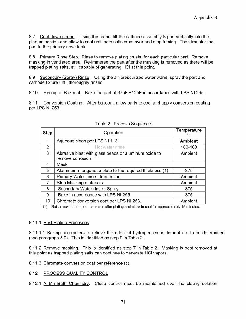
Appendix B
8.7 Cool-down period. Using the crane, lift the cathode assembly & part vertically into the plenum section and allow to cool until bath salts crust over and stop fuming. Then transfer the part to the primary rinse tank. 8.8 Primary Rinse Step. Rinse to remove plating crusts for each particular part. Remove masking in ventilated area. Re-immerse the part after the masking is removed as there will be trapped plating salts, still capable of generating HCl at this point. 8.9 Secondary (Spray) Rinse. Using the air-pressurized water wand, spray the part and cathode fixture until thoroughly rinsed. 8.10 Hydrogen Bakeout. Bake the part at 375F +/-25F in accordance with LPS NI 295. 8.11 Conversion Coating. After bakeout, allow parts to cool and apply conversion coating per LPS NI 253.
Table 2. Process Sequence
Step Operation Temperature °F
1 Aqueous clean per LPS NI 113 Ambient 2 Hot water rinse 160-180 3 Abrasive blast with glass beads or aluminum oxide to
remove corrosion Ambient
4 Mask 5 Aluminum-manganese plate to the required thickness (1) 375 6 Primary Water rinse - Immersion Ambient 7 Strip Masking materials Ambient 8 Secondary Water rinse - Spray 375 9 Bake in accordance with LPS NI 295 375
10 Chromate conversion coat per LPS NI 253. Ambient (1) = Raise rack to the upper chamber after plating and allow to cool for approximately 15 minutes.
8.11.1 Post Plating Processes 8.11.1.1 Baking parameters to relieve the effect of hydrogen embrittlement are to be determined (see paragraph 5.9). This is identified as step 9 in Table 2. 8.11.2 Remove masking. This is identified as step 7 in Table 2. Masking is best removed at this point as trapped plating salts can continue to generate HCl vapors. 8.11.3 Chromate conversion coat per reference (c). 8.12 PROCESS QUALITY CONTROL 8.12.1 Al-Mn Bath Chemistry. Close control must be maintained over the plating solution
71

Appendix B
constituents (aluminum, sodium, potassium, and manganese). Digestion of a small bath sample (0.7-1.5 grams) is accomplished in a 50% nitric acid solution and subsequently analyzed by atomic absorption (AA) in the laboratory (d). Bath samples are also used to determine if contaminant levels in the plating salt have increased to a point requiring replacement of the molten electrolyte. 8.12.1.1 Al-Mn Bath Additions. Chemical additions to the tank to maintain proper chemistry will be in the form of salt granules, round pellets or a powder depending on which chemical is being added. A metal tube will be utilized to direct the additions down through the plenum, bypassing ventilation drafts. This tube will be suspended from the overhead crane when needed. If aluminum-manganese becomes a viable long term plating process then a commercial vendor may be contracted to provide the chemicals in pre-reacted solid, room temperature chunks. Initial charging of an empty tank when fully empty will be accomplished by pre-melting of smaller portions of solution which will be solidified, then lowered into the tank and re-melted. When the level becomes sufficient to operate the tank impeller for positive mixing, subsequent additions can be made in raw material form as for normal additions, through the adder tube. WARNING
Additions of chemicals (primarily aluminum chloride (AlCl3) and manganese chloride (MnCl2)) to the salt bath can be dangerous. Wear appropriate personal protective equipment to prevent breathing fumes during additions. Wear goggles, gloves, apron, and face shield when adding chemicals. Positive ventilation will be provided by makeup air downdraft from the top of the plenum when pouring chemicals through the adder tube. See appropriate MSDS’s.
8.12.2 Anode Pre-Etch Solution. Anode assemblies should be immersion cleaned before each insertion into the plating solution. A tenacious black film forms on the aluminum anodes when electrolyzed in the solution. This film has been found to be copper rich in laboratory analyses of films on aluminum 1100 anodes. Cleaning will be accomplished using a 30-50% nitric acid solution with ~2 ounces per gallon of ammonium bifluoride (NH4F* HF). The anode assembly will be lowered into the etch solution by the overhead crane, soaked for about a minute, and subsequently water rinsed at the spray rinse station, taking precautions not to overspray out of the tank.
WARNING
Specific hazards associated with the anode etch solution are related to the strong acid content which endanger skin, eyes, nose and throat. Use proper ventilation, faceshield / goggles, acid gloves, and apron, when working with this solution, especially when making chemical additions (i.e., pouring concentrated nitric acid and/or adding solid forms of ammonium bifluoride). See appropriate MSDS’s.
8.12.3 Primary Rinse Tank Chemistry. Pressurized sodium carbonate solution (~10%) or sodium hydroxide solution (~50 wt%) will be injected into the Primary rinse tank for pH neutralization. Chemical injections are controlled by an automated chemical feed system based on rinse tank pH as measured by an electrode immersed in the rinse tank. A tube will run from the bottom of the caustic tank to a positive displacement chemical feed pump, sitting on top of the tank, which is then routed to the rinse tank. At the rinse tank, the chemical will be injected via appropriate fittings into to a PVC pipe loop which provides recirculation and mixing to the
72
Appendix B
tank. Tubing connections must be installed securely to avoid the possibility of pressurized caustic solution leaks / sprays during the addition cycles. Conductivity of the rinse water shall be monitored daily to determine when excessive levels of dissolved solids have accumulated. Base hazardous waste personnel shall be contacted to pump out the spent rinse solution. 8.12.4 Spray / Secondary Rinse Tank. Contents of the spray tank will be mainly diluted salts dragged out from the primary rinse tank. However, there will be small amounts of rinse water generated after anode etch, consisting mainly of dilute nitric acid and ammonium bifluoride.
WARNING
Specific hazards associated with the anode etch solution are related to the strong acid content which endanger skin, eyes, nose and throat. Use proper ventilation, faceshield / goggles, acid gloves, and apron, when working with this solution, especially when making chemical additions. See appropriate MSDS’s.
8.13 SAFETY CONSIDERATIONS 8.13.1 SAFETY SHOWER. A safety shower / eyewash station is to be installed within a short distance of where potential exposure areas are located, however, not too close to where contact with molten salt could conceivably occur (i.e., should not drain into the pit which is the secondary containment site for molten salt leaks). 8.13.2 HYDROGEN CHLORIDE GAS. The danger and consequences of hydrogen chloride gas are real and need to be re-emphasized. Every effort should be made to minimize the possibility of contact with water or moisture with the salt bath or the salt bath fumes. Placards reinforcing the “Use No Water” requirement should be used. 8.13.3 MOLTEN SALTS. Reasonable care should be exercised working around heated equipment and hot parts. Extra precautions should be taken during bath drain downs when the molten salt (at or below 375°F) is being drained into holding barrels from the bottom valve. 8.13.4 HOT SURFACES / THERMAL BURNS. Reasonable care should be exercised working around heated equipment and hot parts. 8.13.5 CHEMICAL ADDITIONS TO PROCESS SOLUTIONS. Observe the precautions and procedures discussed in Sec. 8 with regard to chemical adds to the process solutions. Be familiar with appropriate MSDS’s prior to working with chemicals. Personal protective equipment needs to be worn when making chemical additions such as faceshield / goggles, gloves, apron and observing that sufficient ventilation is present. 8.13.6 DISPOSAL OF CONTAMINATED PLATING SALT. At this time, no method of purifying contaminated plating salt has been developed. Contaminated salt will be stored in covered drums and disposed per environmental waste disposal guidelines. 8.13.7 CAUSTIC SOLUTION. Pressurized sodium carbonate solution (~10%) or sodium hydroxide solution (~50 wt%) will be injected into the Primary rinse tank for pH neutralization. Additions are controlled by an automated chemical feed system based on pH as measured by
73

Appendix B
an electrode immersed in the rinse tank. Tubing connections must be installed securely to avoid the possibility of pressurized caustic solution leaks / sprays during the addition cycles. 8.13.8 ANODE ETCH SOLUTION. The anode etch solution is a strong acid (30-50 vol% HNO3 (conc.) with ammonium bifluoride addition. Avoid contact with this solution. Use eyewash/ safety shower in the event of exposure to this solution. 8.13.9 NITROGEN GAS CYLINDER. A cylinder of high pressure nitrogen gas will be used to supply a ~15 psi N2 cap to the impeller shaft seal to prevent ingress of bath fumes and seal degradation. The cylinder will be chained to the wall per local guidelines. 8.13.10 EMERGENCY CONTACT INFORMATION. Contact information for emergency personnel should be clearly posted in the event of a mishap. PREPARED BY: APPROVED BY: E. R. Duffy T. R. Woods Materials Engineer 4.3.4 Depot Team Leader REVIEWED BY: E. Shiwanov Chemist
74

Appendix C
Appendix C Aluminum-Manganese Plating Mock Startup Procedure
AlMn Mock-Startup (performed as noted below week of 8/29/05) Plating Tank
• Fill tank to 200 gallon mark with water (using garden hose probably easiest). Complete • Turn on ventilation to plating tank. Adjust duct valves as needed. Complete. Make sure
lid is off plenum. • Turn on agitator. Determine (through visual observation of tank contents) and record
preferred rpm. Keep agitator on. Done. Set agitator to 16Hz. • Turn on heaters and slowly ramp up temperature such that tank contents reach 90C. Do
not exceed heater/tank surface temp of 232C (450F). Determine and record preferred ramp rate. Keep heater/tank – tank contents deltaT <100C at all times. This step could take a while. Keep a logsheet of temperature/time. Done. Heat up rate is generally 1 degree/5 minutes.
• With tank gate valve open, funnel and screen in place in plenum, and using hoist pick up and pour about 5 lb (record exact amount) of KCl into plating tank. Done. Use digital bathroom scale to weigh adds. Use aluminum stockpot and hoist to make adds if needed. Open gate valve before and close gate valve after chemical adds. Observe KCl sucked through plenum ventilation using sight glass in plenum – adjust funnel height over plenum as needed to minimize losses. Done previously.
Prep plating computer before next step. Cathode/Anode
• Adjust duct valves to ventilate nitric acid tank. Done. • Using hoist dip cathode fixture in nitric etch tank then rinse, dry and set on fixture hook.
Done. If dirty/greasy then acetone wipe prior to etch. • Using hoist dip anode fixture in nitric etch tank, then rinse, dry. Done. Removed top two
basket sections b/c difficult to thoroughly dry mated seams. • Adjust duct valves to ventilate plating tank. Done. • Connect anode cable to anode fixture then lower anode fixture into plating tank. Done.
Reversed order due to new cable attachment point outside of plenum. • Place dummy lid on anode in plating tank. Done. • Prepare the part to be plated by cleaning/grit blast. Done. • Attach the part and cathode cable to cathode fixture. Done. • Remove and rinse/dry dummy lid then lower cathode fixture into plating tank. Done. • Do NOT operate rectifier. Done – operated rectifier okay.
Rinsing
• Turn on pH control system and circulation pump for rinse tank #1, verify operating properly. Remove blanking plate if needed. Done. Performed smoke test with blanking
75

Appendix C
plate on, vent’l sufficiently captured fumes upto within 6-8” of edge of tank furthest from the vent’l.
• Lift cathode fixture out of plating tank and dwell in plenum for 5 minutes. Done. • Lift cathode fixture out of plenum and lower fixture into rinse tank #1. Done. • Place dummy lid into plenum on anode fixture. Done. • Remove cathode cable from fixture. Done. Do this prior to lifting cathode up into
plenum for dwell. • Lift cathode fixture out of rinse tank #1 and move it to rinse tank #2. Spray fixture and
part with water gun, then dry. Done. • Remove part from fixture and wrap in chem wipe. Done. Remove part at rinse tank 1
while submerged in water. • Remove and rinse/dry dummy lid. Done. • Remove and rinse/dry anode fixture. Done.
Sample plating bath
• Attach sampling cup to measure/sample tool. Done. • Using hoist lower tool into plating tank, then lift back up into plenum and dwell. Done. • Collect sample from cup while cup in/over plenum. Done. Note: objects over open
tank). • Place tool with cup still attached into rinse tank #1, then rinse tank #2 spray and dry.
Done. Need to tip the cup to empty water out of it. • Send sample to lab for analysis (in this case concentration of KCl).
Empty plating tank • Turn heat to plating tank off. • Place waste drum on scale under plating tank, place tank hose into lid opening and
ventilation hose into lid opening. Tare the scale. • Fill the drum with 320lbs of water (40 gallons). • Repeat until tank is empty (5 drums). • Leave gate valve open so residual water can evaporate through the plenum (should
happen quickly if ventilation is on). Recheck all torques after the plating tank has cooled down. “Brick” loading (load pre-fused, solid, room temp plating bath “bricks”)
• Fill bricking bucket ½ full of water. Using hoist lower bucket into plating tank and empty water into tank. Lift bucket up out of plating tank. Done.
Emergency Response System
• Initiate system using water feed. Observe inside of plating tank with system initiated. • Initiate system using Krytox feed. Direct the feed lines into buckets and capture the
Krytox rather than letting it feed pit and plating tank.
76

Appendix D
77
Appendix D Analytical Methods Supporting the Experimental Design
ASTM D 4691 “Standard Practice for Measuring Elements in Water by Flame Atomic Absorption Spectrophotometry” ASTM D 1976 “Standard Test Method for Elements in Water by Inductively-Coupled Argon Plasma Emission Spectroscopy” “Determination of Oxide Ions in Aluminum Chloride – Alkali Chloride Melts by Karl Fischer Titration,” Analytical Chemistry, 1993, Volume 65, Number 9, Pages 1210-1212. “Removal of Oxide Impurities from Alkali Haloaluminate Melts Using Carbon Tetrachloride,” J. Electrochem. Soc., Vol. 140, No. 6, June 1993. ASTM B 499 “Standard Test Method for Measurement of Coating Thickness by the Magnetic Method: Nonmagnetic Coatings on Magnetic Base Metals” ASTM E 1508 “Standard Guide for Quantitative Analysis by Energy-Dispersive Spectroscopy” ASTM E 1251 “Standard Test Method for Optical Emission Spectrometric Analysis of Aluminum and Aluminum Alloys by the Argon Atmosphere, Point-To-Plane, Unipolar Self-Initiating Capacitor Discharge R(1999)” ASTM F 519-97 “Standard Test Method for Mechanical Hydrogen Embrittlement Evaluation of Plating Processes and Service Environments.