Embed Size (px)
Citation preview
Filters and QoS for ERS 8600 R-Series Modules Technical Configuration Guide
Avaya Data Solutions Document Date: July 2010 Document Number: NN48500-541 Document Version: 1.4
Ethernet Routing Switch 8600 R-Series
Engineering
Filters and QoS for ERS 8600 R-Series Modules Technical Configuration Guide
2 July 2010
avaya.com
© 2010 Avaya Inc. All Rights Reserved.
Notices While reasonable efforts have been made to ensure that the information in this document is complete and accurate at the time of printing, Avaya assumes no liability for any errors. Avaya reserves the right to make changes and corrections to the information in this document without the obligation to notify any person or organization of such changes.
Documentation disclaimer Avaya shall not be responsible for any modifications, additions, or deletions to the original published version of this documentation unless such modifications, additions, or deletions were performed by Avaya. End User agree to indemnify and hold harmless Avaya, Avaya‘s agents, servants and employees against all claims, lawsuits, demands and judgments arising out of, or in connection with, subsequent modifications, additions or deletions to this documentation, to the extent made by End User.
Link disclaimer Avaya is not responsible for the contents or reliability of any linked Web sites referenced within this site or documentation(s) provided by Avaya. Avaya is not responsible for the accuracy of any information, statement or content provided on these sites and does not necessarily endorse the products, services, or information described or offered within them. Avaya does not guarantee that these links will work all the time and has no control over the availability of the linked pages.
Warranty Avaya provides a limited warranty on this product. Refer to your sales agreement to establish the terms of the limited warranty. In addition, Avaya‘s standard warranty language, as well as information regarding support for this product, while under warranty, is available to Avaya customers and other parties through the Avaya Support Web site: http://www.avaya.com/support Please note that if you acquired the product from an authorized reseller, the warranty is provided to you by said reseller and not by Avaya.
Licenses THE SOFTWARE LICENSE TERMS AVAILABLE ON THE AVAYA WEBSITE, HTTP://SUPPORT.AVAYA.COM/LICENSEINFO/ ARE APPLICABLE TO ANYONE WHO DOWNLOADS, USES AND/OR INSTALLS AVAYA SOFTWARE, PURCHASED FROM AVAYA INC., ANY AVAYA AFFILIATE, OR AN AUTHORIZED AVAYA RESELLER (AS APPLICABLE) UNDER A COMMERCIAL AGREEMENT WITH AVAYA OR AN AUTHORIZED AVAYA RESELLER. UNLESS OTHERWISE AGREED TO BY AVAYA IN WRITING, AVAYA DOES NOT EXTEND THIS LICENSE IF THE SOFTWARE WAS OBTAINED FROM ANYONE OTHER THAN AVAYA, AN AVAYA AFFILIATE OR AN AVAYA AUTHORIZED RESELLER, AND AVAYA RESERVES THE RIGHT TO TAKE LEGAL ACTION AGAINST YOU AND ANYONE ELSE USING OR SELLING THE SOFTWARE WITHOUT A LICENSE. BY INSTALLING, DOWNLOADING OR USING THE SOFTWARE, OR AUTHORIZING OTHERS TO DO SO, YOU, ON BEHALF OF YOURSELF AND THE ENTITY FOR WHOM YOU ARE INSTALLING, DOWNLOADING OR USING THE SOFTWARE (HEREINAFTER REFERRED TO INTERCHANGEABLY AS "YOU" AND "END USER"), AGREE TO THESE TERMS AND CONDITIONS AND CREATE A BINDING CONTRACT BETWEEN YOU AND AVAYA INC. OR THE APPLICABLE AVAYA AFFILIATE ("AVAYA").
Copyright Except where expressly stated otherwise, no use should be made of the Documentation(s) and Product(s) provided by Avaya. All content in this documentation(s) and the product(s) provided by Avaya including the selection, arrangement and design of the content is owned either by Avaya or its licensors and is protected by copyright and other intellectual property laws including the sui generis rights relating to the protection of databases. You may not modify, copy, reproduce, republish, upload, post, transmit or distribute in any way any content, in whole or in part, including any code and software. Unauthorized reproduction, transmission, dissemination, storage, and or use without the express written consent of Avaya can be a criminal, as well as a civil offense under the applicable law.
Third Party Components Certain software programs or portions thereof included in the Product may contain software distributed under third party agreements ("Third Party Components"), which may contain terms that expand or limit rights to use certain portions of the Product ("Third Party Terms"). Information regarding distributed Linux OS source code (for those Products that have distributed the Linux OS source code), and identifying the copyright holders of the Third Party Components and the Third Party Terms that apply to them is available on the Avaya Support Web site: http://support.avaya.com/Copyright.
Trademarks The trademarks, logos and service marks ("Marks") displayed in this site, the documentation(s) and product(s) provided by Avaya are the registered or unregistered Marks of Avaya, its affiliates, or other third parties. Users are not permitted to use such Marks without prior written consent from Avaya or such third party which may own the Mark. Nothing contained in this site, the documentation(s) and product(s) should be construed as granting, by implication, estoppel, or otherwise, any license or right in and to the Marks without the express written permission of Avaya or the applicable third party. Avaya is a registered trademark of Avaya Inc. All non-Avaya trademarks are the property of their respective owners.
Downloading documents For the most current versions of documentation, see the Avaya Support. Web site: http://www.avaya.com/support
Contact Avaya Support Avaya provides a telephone number for you to use to report problems or to ask questions about your product. The support telephone number is 1-800-242-2121 in the United States. For additional support telephone numbers, see the Avaya Web site: http://www.avaya.com/support

Filters and QoS for ERS 8600 R-Series Modules Technical Configuration Guide
3 July 2010
avaya.com
Revision Control
No Date Version Revised by Remarks
Filters and QoS for ERS 8600 R-Series Modules Technical Configuration Guide
4 July 2010
avaya.com
Table of Contents
Figures ......................................................................................................................................................... 6
Tables ........................................................................................................................................................... 7
Document Updates ..................................................................................................................................... 8
1. Overview: R-Module Filter Specifications ........................................................................................ 9
1.1 Access Control Templates (ACT).................................................................................................. 9
1.2 Access Control Entry (ACE) ........................................................................................................ 12
1.3 Access Control Lists (ACL) ......................................................................................................... 14
2. Configuring ACLs ............................................................................................................................. 15
2.1 ACT – Access Control Templates ............................................................................................... 15
2.2 ACL ............................................................................................................................................. 17
2.3 ACE – Access Control Entry ....................................................................................................... 20
3. R-Module Queuing ............................................................................................................................ 27
3.1 Overview ..................................................................................................................................... 27
3.2 Default Packet QoS to Egress Queue Mapping .......................................................................... 28
3.3 Default Ingress p-bit to Internal QoS Level and Egress Queue Mapping ................................... 29
3.4 Gigabit Ethernet Default Ingress DSCP to Egress Queue Mapping ........................................... 29
3.5 Egress Traffic Shaping ................................................................................................................ 30
3.6 Queue Set Configuration Commands ......................................................................................... 33
4. Ingress Traffic Policing .................................................................................................................... 39
4.1 Policing Configuration ................................................................................................................. 40
5. QoS Concepts.................................................................................................................................... 42
5.1 Changing the DiffServ Port Type ................................................................................................ 42
5.2 L2 and L3 Trusted and Untrusted Ports ...................................................................................... 42
5.3 QoS for R-Mode Modules ........................................................................................................... 52
5.4 Changing the Default Port or VLAN QoS Levels ........................................................................ 53
5.5 Adding a MAC QoS Level ........................................................................................................... 54
6. Configuration Examples ................................................................................................................... 55
6.1 Configuration Example 1: Marking and Dropping Traffic ............................................................ 55
6.2 Configuration Example 2: Filter Ranges and Policing ................................................................ 64
6.3 Configuration Example 3: Setting Egress Queue Weight and Shaping Rate ............................. 67
6.4 Configuration Example – Changing Egress Port Shaper ............................................................ 72
6.5 Configuration Example – Deny ARP/MAC Spoofing Attack in a Layer 2 Environment .............. 72
6.6 Configuration Example – DoS Attacks ........................................................................................ 76

Filters and QoS for ERS 8600 R-Series Modules Technical Configuration Guide
5 July 2010
avaya.com
6.7 Configuration Example – Port Mirror with ACL‘s ......................................................................... 84
7. Appendix A – Configuration Files ................................................................................................... 89
7.1 From Example 6.1 ....................................................................................................................... 89
7.2 From Example 6.2 ....................................................................................................................... 90
7.3 From Example 6.3 ....................................................................................................................... 91
7.4 From Example 6.4 ....................................................................................................................... 91
7.5 From Example 6.6 ....................................................................................................................... 92
8. Appendix B – Pre-Defined ACT List ................................................................................................ 94
9. Appendix C – QoS Details ................................................................................................................ 96
9.1 Ethernet 802.1Q Tag in Ethernet Header ................................................................................... 96
9.2 DiffServ: QoS at Layer 3 ............................................................................................................. 97
9.3 Ethernet Routing Switch (ERS) 8600 DSCP ToS/IP Mapping .................................................... 98
10. Appendix D – Hardware Overview ............................................................................................... 99
11. Software Baseline: ...................................................................................................................... 100
Reference Documentation: .................................................................................................................... 101
12. Customer service ........................................................................................................................ 102
12.1 Getting technical documentation ............................................................................................... 102
12.2 Getting product training ............................................................................................................. 102
12.3 Getting help from a distributor or reseller .................................................................................. 102
12.4 Getting technical support from the Avaya Web site .................................................................. 102
Filters and QoS for ERS 8600 R-Series Modules Technical Configuration Guide
6 July 2010
avaya.com
Figures
Figure 1: ACT, ACL, and ACE Relationship ................................................................................................. 9
Figure 2: Egress Traffic Shaping ................................................................................................................ 30
Figure 3: Ingress Policing (L2-L7) ............................................................................................................... 39
Figure 4: DiffServ Network Model ............................................................................................................... 42
Figure 5: Diffserv Access Mode – 802.1p Override .................................................................................... 45
Figure 6: DiffServ Core Mode – 802.1p Override Enabled ......................................................................... 46
Figure 7: DiffServ Core Ports – 802.1p Override Disable ........................................................................... 47
Figure 8: DiffServ Access Mode – 802.1p Override Disabled .................................................................... 48
Figure 9: DiffServ Disabled ......................................................................................................................... 49
Figure 10: Access Control Lists .................................................................................................................. 50
Figure 11: Access Control Lists Continued ................................................................................................. 51
Figure 12: Example 1 Diagram ................................................................................................................... 55
Figure 13: Filter Ranges and Policing ......................................................................................................... 64
Figure 14: Deny ARP/MAC Spoofing Attack ............................................................................................... 72
Figure 15: 802.1Q Ethernet Header ............................................................................................................ 96
Figure 16: DiffServ Code Point ................................................................................................................... 97
Filters and QoS for ERS 8600 R-Series Modules Technical Configuration Guide
7 July 2010
avaya.com
Tables
Table 1: ACT Attributes ............................................................................................................................... 10
Table 2: Global ACL Actions ....................................................................................................................... 13
Table 3: Ethernet Interface Type Default Internal QoS Mapping ................................................................ 28
Table 4: Default p-bit Interface Internal QoS Level and Egress Queue Mapping....................................... 29
Table 5: L2 and L3 Trusted Port Actions .................................................................................................... 43
Table 6: L2 and L3 Untrusted Port Actions ................................................................................................. 44
Table 7: L2 Trusted and L3 Untrusted Port Actions .................................................................................... 44
Table 8: L2 Untrusted and L3 Trusted Port Actions .................................................................................... 44
Table 9: QoS Features Supported .............................................................................................................. 52
Table 10: PP8600 DSCP ToS/IP Mapping ................................................................................................. 98

Filters and QoS for ERS 8600 R-Series Modules Technical Configuration Guide
8 July 2010
avaya.com
Document Updates
July 30, 2010
Filters and QoS for ERS 8600 R-Series Modules Technical Configuration Guide
9 July 2010
avaya.com
1. Overview: R-Module Filter Specifications
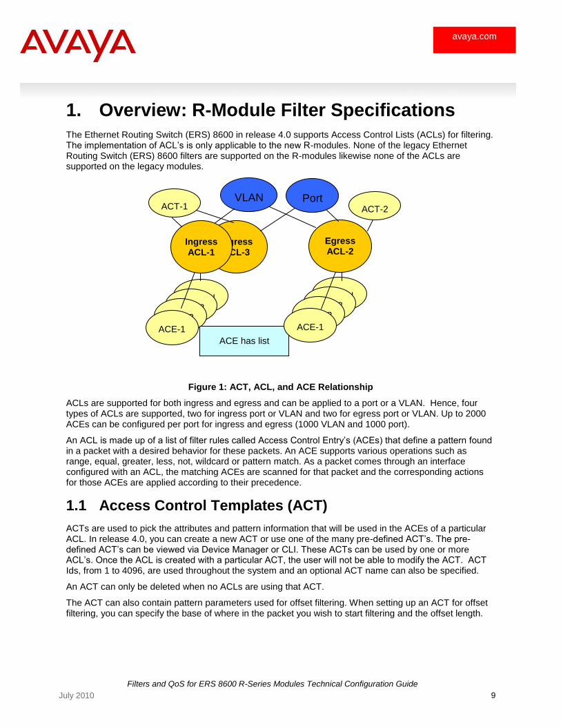
The Ethernet Routing Switch (ERS) 8600 in release 4.0 supports Access Control Lists (ACLs) for filtering. The implementation of ACL‘s is only applicable to the new R-modules. None of the legacy Ethernet Routing Switch (ERS) 8600 filters are supported on the R-modules likewise none of the ACLs are supported on the legacy modules.
Figure 1: ACT, ACL, and ACE Relationship
ACLs are supported for both ingress and egress and can be applied to a port or a VLAN. Hence, four types of ACLs are supported, two for ingress port or VLAN and two for egress port or VLAN. Up to 2000 ACEs can be configured per port for ingress and egress (1000 VLAN and 1000 port).
An ACL is made up of a list of filter rules called Access Control Entry‘s (ACEs) that define a pattern found in a packet with a desired behavior for these packets. An ACE supports various operations such as range, equal, greater, less, not, wildcard or pattern match. As a packet comes through an interface configured with an ACL, the matching ACEs are scanned for that packet and the corresponding actions for those ACEs are applied according to their precedence.
1.1 Access Control Templates (ACT)
ACTs are used to pick the attributes and pattern information that will be used in the ACEs of a particular ACL. In release 4.0, you can create a new ACT or use one of the many pre-defined ACT‘s. The pre-defined ACT‘s can be viewed via Device Manager or CLI. These ACTs can be used by one or more ACL‘s. Once the ACL is created with a particular ACT, the user will not be able to modify the ACT. ACT Ids, from 1 to 4096, are used throughout the system and an optional ACT name can also be specified.
An ACT can only be deleted when no ACLs are using that ACT.
The ACT can also contain pattern parameters used for offset filtering. When setting up an ACT for offset filtering, you can specify the base of where in the packet you wish to start filtering and the offset length.
VLAN
ACE-N ACE-3
ACE-2
ACE-1
ACE has list
of ports and MLTs
ACE-N ACE-3
ACE-2
ACE-1
ACT-1
Ingress ACL-3
Ingress ACL-1
Egress ACL-2
Port ACT-2
Filters and QoS for ERS 8600 R-Series Modules Technical Configuration Guide
10 July 2010
avaya.com
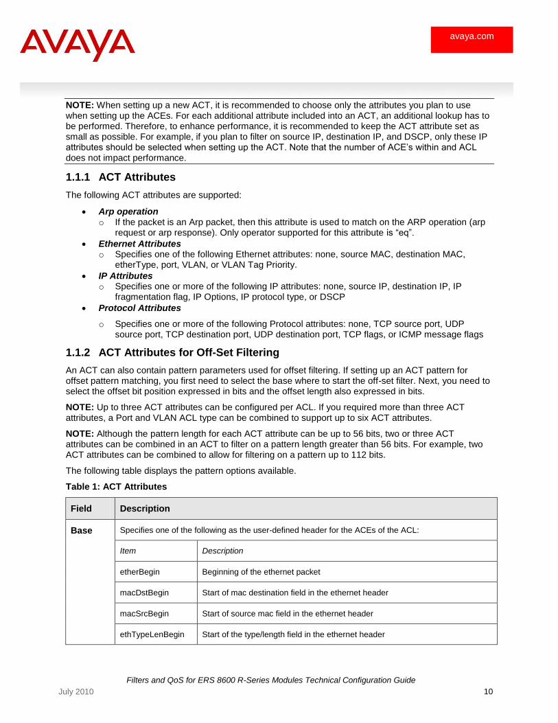
NOTE: When setting up a new ACT, it is recommended to choose only the attributes you plan to use when setting up the ACEs. For each additional attribute included into an ACT, an additional lookup has to be performed. Therefore, to enhance performance, it is recommended to keep the ACT attribute set as small as possible. For example, if you plan to filter on source IP, destination IP, and DSCP, only these IP attributes should be selected when setting up the ACT. Note that the number of ACE‘s within and ACL does not impact performance.
1.1.1 ACT Attributes
The following ACT attributes are supported:
Arp operation o If the packet is an Arp packet, then this attribute is used to match on the ARP operation (arp
request or arp response). Only operator supported for this attribute is ―eq‖.
Ethernet Attributes o Specifies one of the following Ethernet attributes: none, source MAC, destination MAC,
etherType, port, VLAN, or VLAN Tag Priority.
IP Attributes o Specifies one or more of the following IP attributes: none, source IP, destination IP, IP
fragmentation flag, IP Options, IP protocol type, or DSCP
Protocol Attributes
o Specifies one or more of the following Protocol attributes: none, TCP source port, UDP source port, TCP destination port, UDP destination port, TCP flags, or ICMP message flags
1.1.2 ACT Attributes for Off-Set Filtering
An ACT can also contain pattern parameters used for offset filtering. If setting up an ACT pattern for offset pattern matching, you first need to select the base where to start the off-set filter. Next, you need to select the offset bit position expressed in bits and the offset length also expressed in bits.
NOTE: Up to three ACT attributes can be configured per ACL. If you required more than three ACT attributes, a Port and VLAN ACL type can be combined to support up to six ACT attributes.
NOTE: Although the pattern length for each ACT attribute can be up to 56 bits, two or three ACT attributes can be combined in an ACT to filter on a pattern length greater than 56 bits. For example, two ACT attributes can be combined to allow for filtering on a pattern up to 112 bits.
The following table displays the pattern options available.
Table 1: ACT Attributes
Field Description
Base Specifies one of the following as the user-defined header for the ACEs of the ACL:
Item Description
etherBegin Beginning of the ethernet packet
macDstBegin Start of mac destination field in the ethernet header
macSrcBegin Start of source mac field in the ethernet header
ethTypeLenBegin Start of the type/length field in the ethernet header
Filters and QoS for ERS 8600 R-Series Modules Technical Configuration Guide
11 July 2010
avaya.com
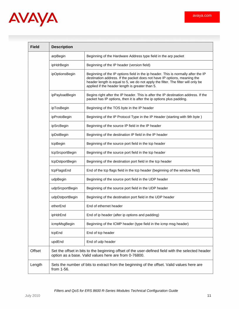
Field Description
arpBegin Beginning of the Hardware Address type field in the arp packet
ipHdrBegin Beginning of the IP header (version field)
ipOptionsBegin Beginning of the IP options field in the ip header. This is normally after the IP destination address. If the packet does not have IP options, meaning the header length is equal to 5, we do not apply the filter. The filter will only be applied if the header length is greater than 5.
ipPayloadBegin Begins right after the IP header. This is after the IP destination address. If the packet has IP options, then it is after the ip options plus padding.
ipTosBegin Beginning of the TOS byte in the IP header
ipProtoBegin Beginning of the IP Protocol Type in the IP Header (starting with 9th byte )
ipSrcBegin Beginning of the source IP field in the IP header
ipDstBegin Beginning of the destination IP field in the IP header
tcpBegin Beginning of the source port field in the tcp header
tcpSrcportBegin Beginning of the source port field in the tcp header
tcpDstportBegin Beginning of the destination port field in the tcp header
tcpFlagsEnd End of the tcp flags field in the tcp header (beginning of the window field)
udpBegin Beginning of the source port field in the UDP header
udpSrcportBegin Beginning of the source port field in the UDP header
udpDstportBegin Beginning of the destination port field in the UDP header
etherEnd End of ethernet header
ipHdrEnd End of ip header (after ip options and padding)
icmpMsgBegin Beginning of the ICMP header (type field in the icmp msg header)
tcpEnd End of tcp header
updEnd End of udp header
Offset Set the offset in bits to the beginning offset of the user-defined field with the selected header option as a base. Valid values here are from 0-76800.
Length Sets the number of bits to extract from the beginning of the offset. Valid values here are from 1-56.
Filters and QoS for ERS 8600 R-Series Modules Technical Configuration Guide
12 July 2010
avaya.com
1.2 Access Control Entry (ACE)
ACEs are configured with a set of values along with the actions to be taken if a packet matches a particular ACE. If an attribute specified in the ACT does not have a value specified in the ACE, then that attribute value will be treated as a wildcard.
The attributes that can be specified for an ACE are divided into several categories since they cannot be specified on the same command line. The categories are Ethernet, Arp, IP, Protocol and Advanced. The actions can be specified by the ―action‖ and ―debug‖ commands.
The values for the attributes can be specified using several operators like equal-to, not-equal-to, less-than-or-equal-to, greater-than-or-equal-to. If the equal-to and not-equal-to operators are used, the user can specify a list and/or a range of values. A single value has to be specified for the other 2 operators. There are some special operators that are used with specific attributes. They are match-any, match-all, prefix-list and any. These operators will be discussed later in this section.
Since an ACE configuration takes several command lines, the default state of the ACE when it is created is ―disabled‖. An explicit ―enable‖ command has to be issued to enable the ACE. The user will not be able to enable the ACE until at least the ―action‖ command has been entered. Note that multiple entries for the same ACE can be entered in one command line using a semicolon ―;‖ between entries.
After the ACE is enabled, the ACE cannot be modified except for the ―debug‖ actions. The ACE has to be disabled, modified and then re-enabled to make any modifications.
If L3 and L4 attributes are configured, ACEs are applied to the non-fragments and the initial fragment of an IP packet.
A maximum of 500 port ACEs and 500 VLAN ingress ACEs plus a total of 500 port and 500 VLAN egress ACEs can be configured per port for a total of 2000 ACEs per port. The total number of ACE‘s that can be configured is 10,000 ingress and 10,000 egress. Up to 1,000 ingress and 1,000 egress ACE‘s can have the count flag enabled.
1.2.1 ACE Actions
An ACL can contain multiple ACEs where each ACE can have a corresponding action of permit or deny. The default action of permit is applied when there are no ACE matches for a particular packet. An ACL can also have a global action which is applied to all ACEs applied to this ACL. The default global action is none. You can modify the default action and global action at any time.

Filters and QoS for ERS 8600 R-Series Modules Technical Configuration Guide
13 July 2010
avaya.com
Table 2: Global ACL Actions
Ingress (port, VLAN-based)
Match criteria
MAC, p-bits, VLAN tag,
ARP, IP, TOS, DSCP,
TCP, and UDP
Match pattern
Base, offset, and
length
Action
Permit, deny, redirect to next hop, redirect to MLT index, remark-dot1p/DSCP, police, send to egress queue, mirror count
Egress (port, VLAN-based)
Match criteria
MAC, p-bits, VLAN tag,
ARP, IP, TOS, DSCP,
TCP, and UDP
Match pattern
Base, offset, and
length
Action
Permit, deny, mirror
Priority
Based on ID (portACL before VlanACL)
If a packet matches multiple ACEs, the non-contradicting actions of all ACEs according to their precedence (ACE Id) will be taken. If a stop-on-match flag is specified for an ACE, filtering will stop and the specified action for this ACE will be taken.
1.2.2 Priority of ACEs
If a packet matches multiple ACEs in an ACL, the actions of the highest priority ACE will be applied. The actions of the remaining ACEs will be applied only if the mode is the same as the highest priority ACE, and the actions were non-overlapping with the highest priority ACE.
Here are a few examples:
Example 1 Example 2
ACE 1 - mode permit, actions - police
ACE 2 - mode deny, actions mirror
ACE 1 - mode deny, actions mirror
ACE 2 - mode permit, actions - police
We apply the actions of only ACE 1 We apply the actions of only ACE 1
Example 3 Example 4
ACE 1 - mode permit, actions - police
ACE 2 - mode deny, actions - mirror
ACE 3 - mode permit, actions - police, mirror
ACE 4 - mode permit, actions remark-dscp
ACE 1 - mode permit, actions - police
ACE 2 - mode deny, actions - mirror
ACE 3 - mode permit, actions - mirror, stop-on-match
ACE 4 - mode permit, actions remark-dscp
We apply the actions of ACE 1 and ACE 4 The actions of ACE1 and ACE3 are applied
Filters and QoS for ERS 8600 R-Series Modules Technical Configuration Guide
14 July 2010
avaya.com
1.3 Access Control Lists (ACL)
ACLs are used to group filter rules called ACEs. An ACL can be applied to a VLAN or a Port on the Ingress or Egress. A VLAN or a Port can only be associated with one Ingress ACL and one Egress ACL.
When an ACL is created, by default, it will come up in the enabled state. If an ACL is disabled, all ACEs within that ACL will be disabled. When the ACL is re-enabled again, the ACEs that were enabled previously will get enabled.
If an ACL is deleted, all ACEs within the ACL will also be deleted.
Since both port based and vlan based ACLs are supported, depending on the configuration, the actions of both ACLs to a particular packet may be applied. In this case, the port based ACL actions get preference, and will be applied first.
The default action is applied when there are no ACE matches for a particular packet. The global actions will be applied to all ACEs that match a particular packet. The default action value is ―permit‖, and the default global action is ―none‖. The default action and global action can be modified anytime.
1.3.1 Priority of ACLs
A user can configure both port based ACLs and vlan based ACLs. It is advisable to apply only one type of ACL to a packet, however, depending on the configuration, there may be cases where the actions of both port based ACLs and vlan based ACLs have to be applied to a packet. In this case, we apply the port based ACL actions first. We will apply vlan based ACL actions only if the mode is same as port based ACL and the vlan based ACL has ACEs with non-overlapping actions with the port based ACL actions.
Here are a few examples:
Example 1 Example 2
Port ACL - mode permit, some actions
Vlan ACL - mode deny, some actions
Port ACL:
o ACE 1: mode permit, action – police
Vlan ACL:
o ACE 1 : mode permit, action – police
o ACE 2 : mode permit, action remark-dscp
We apply the actions of Port ACL only We apply the actions of port ACL and actions of ACE 2 of VLAN ACL.
Example 3
Port ACL:
o ACE 1: mode permit, action – police
Vlan ACL:
o ACE 1 : mode permit, action - police, remark-dscp
The actions of port ACL are only applied.
Filters and QoS for ERS 8600 R-Series Modules Technical Configuration Guide
15 July 2010
avaya.com
2. Configuring ACLs
To configure an ACL, you need to configure the following items in the following order:
1. Create an ACT or use one of the pre-defined ACT‘s
2. Create an ACL using an ACT from Step 1 above.
3. Add the appropriate ACE‘s to the ACL created in Step 2 above.
2.1 ACT – Access Control Templates
As pointed out in section 1.1, there are several pre-defined ACT‘s available. You have the choice of using an existing ACT or if you wish, create a new one. To view the ACT list, enter the following command:
ERS-8610:5# show filter act
Please see Appendix B showing output from the show filter act command.
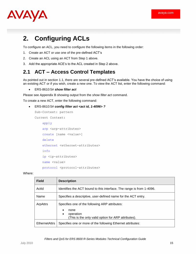
To create a new ACT, enter the following command:
ERS-8610:5# config filter act <act id, 1-4096> ?
Sub-Context: pattern
Current Context:
apply
arp <arp-attributes>
create [name <value>]
delete
ethernet <ethernet-attributes>
info
ip <ip-attributes>
name <value>
protocol <protocol-attributes>
Where:
Field Description
ActId Identifies the ACT bound to this interface. The range is from 1-4096.
Name Specifies a descriptive, user-defined name for the ACT entry.
ArpAttrs Specifies one of the following ARP attributes:
none
operation (This is the only valid option for ARP attributes).
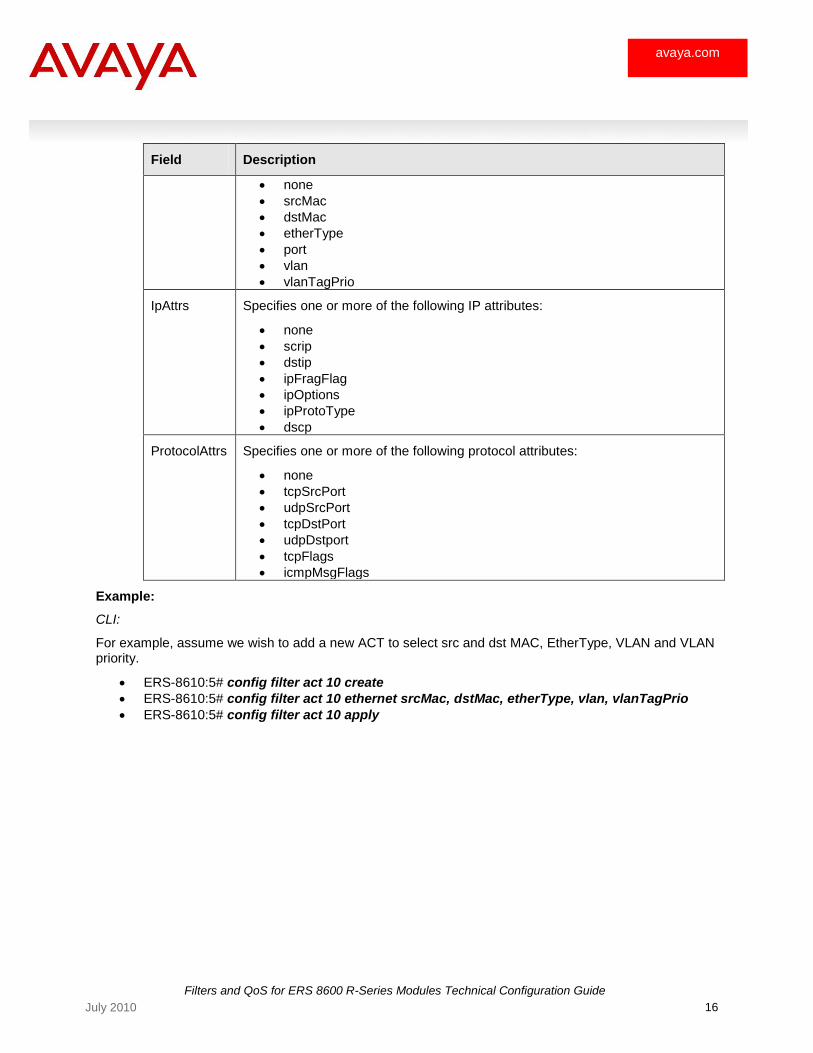
EthernetAttrs Specifies one or more of the following Ethernet attributes:
Filters and QoS for ERS 8600 R-Series Modules Technical Configuration Guide
16 July 2010
avaya.com
Field Description
none
srcMac
dstMac
etherType
port
vlan
vlanTagPrio
IpAttrs Specifies one or more of the following IP attributes:
none
scrip
dstip
ipFragFlag
ipOptions
ipProtoType
dscp
ProtocolAttrs Specifies one or more of the following protocol attributes:
none
tcpSrcPort
udpSrcPort
tcpDstPort
udpDstport
tcpFlags
icmpMsgFlags
Example:
CLI:
For example, assume we wish to add a new ACT to select src and dst MAC, EtherType, VLAN and VLAN priority.
ERS-8610:5# config filter act 10 create
ERS-8610:5# config filter act 10 ethernet srcMac, dstMac, etherType, vlan, vlanTagPrio
ERS-8610:5# config filter act 10 apply

Filters and QoS for ERS 8600 R-Series Modules Technical Configuration Guide
17 July 2010
avaya.com
Device Manager:
Via Security>Advanced L2-L7 Filter>ACL>ACT>Insert
2.2 ACL
The next step is to create an ACL. This can be accomplished by entering the following command:
CLI:
ERS-8610:5# config filter acl <acl-id 1-4096> ?
Sub-Context: ace port set vlan
Current Context:
create <type> act <value> [name <value>]
delete
disable
enable
info
name <value>
ERS-8610:5# config filter acl <acl-id 1-4096> create ?
create an access control list
Required parameters:
<type> = {inVlan|outVlan|inPort|outPort}
act <value> = access control template ID {1..4096}
Optional parameters:
name <value> = access control list descriptive name {string length 0..32}
Filters and QoS for ERS 8600 R-Series Modules Technical Configuration Guide
18 July 2010
avaya.com
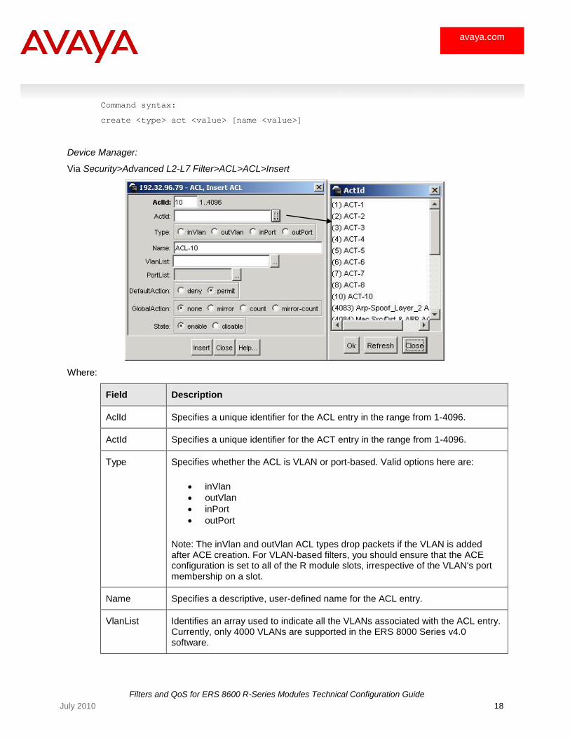
Command syntax:
create <type> act <value> [name <value>]
Device Manager:
Via Security>Advanced L2-L7 Filter>ACL>ACL>Insert
Where:
Field Description
AclId Specifies a unique identifier for the ACL entry in the range from 1-4096.
ActId Specifies a unique identifier for the ACT entry in the range from 1-4096.
Type Specifies whether the ACL is VLAN or port-based. Valid options here are:
inVlan
outVlan
inPort
outPort
Note: The inVlan and outVlan ACL types drop packets if the VLAN is added after ACE creation. For VLAN-based filters, you should ensure that the ACE configuration is set to all of the R module slots, irrespective of the VLAN's port membership on a slot.
Name Specifies a descriptive, user-defined name for the ACL entry.
VlanList Identifies an array used to indicate all the VLANs associated with the ACL entry. Currently, only 4000 VLANs are supported in the ERS 8000 Series v4.0 software.
Filters and QoS for ERS 8600 R-Series Modules Technical Configuration Guide
19 July 2010
avaya.com
PortList Specifies the ports to be added to the ACL entry.
DefaultAction Specifies the action to be taken when none of the ACEs in the ACL match. Valid options are deny and permit, with permit as the default.
GlobalAction Indicates action is applied to all ACEs that match in an ACL. Valid options here are:
none
mirror
count
mirror-count
State Enables or disables all of the ACEs in the ACL. The default value is enable
AceListSize Specifies the number of ACEs in a particular ACL.
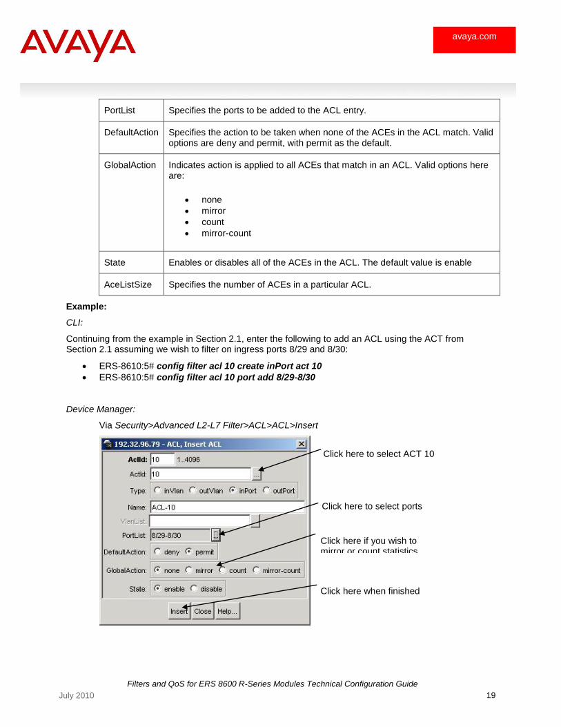
Example:
CLI:
Continuing from the example in Section 2.1, enter the following to add an ACL using the ACT from Section 2.1 assuming we wish to filter on ingress ports 8/29 and 8/30:
ERS-8610:5# config filter acl 10 create inPort act 10
ERS-8610:5# config filter acl 10 port add 8/29-8/30
Device Manager:
Via Security>Advanced L2-L7 Filter>ACL>ACL>Insert
Click here to select ACT 10
Click here to select ports
Click here when finished
Click here if you wish to mirror or count statistics
Filters and QoS for ERS 8600 R-Series Modules Technical Configuration Guide
20 July 2010
avaya.com
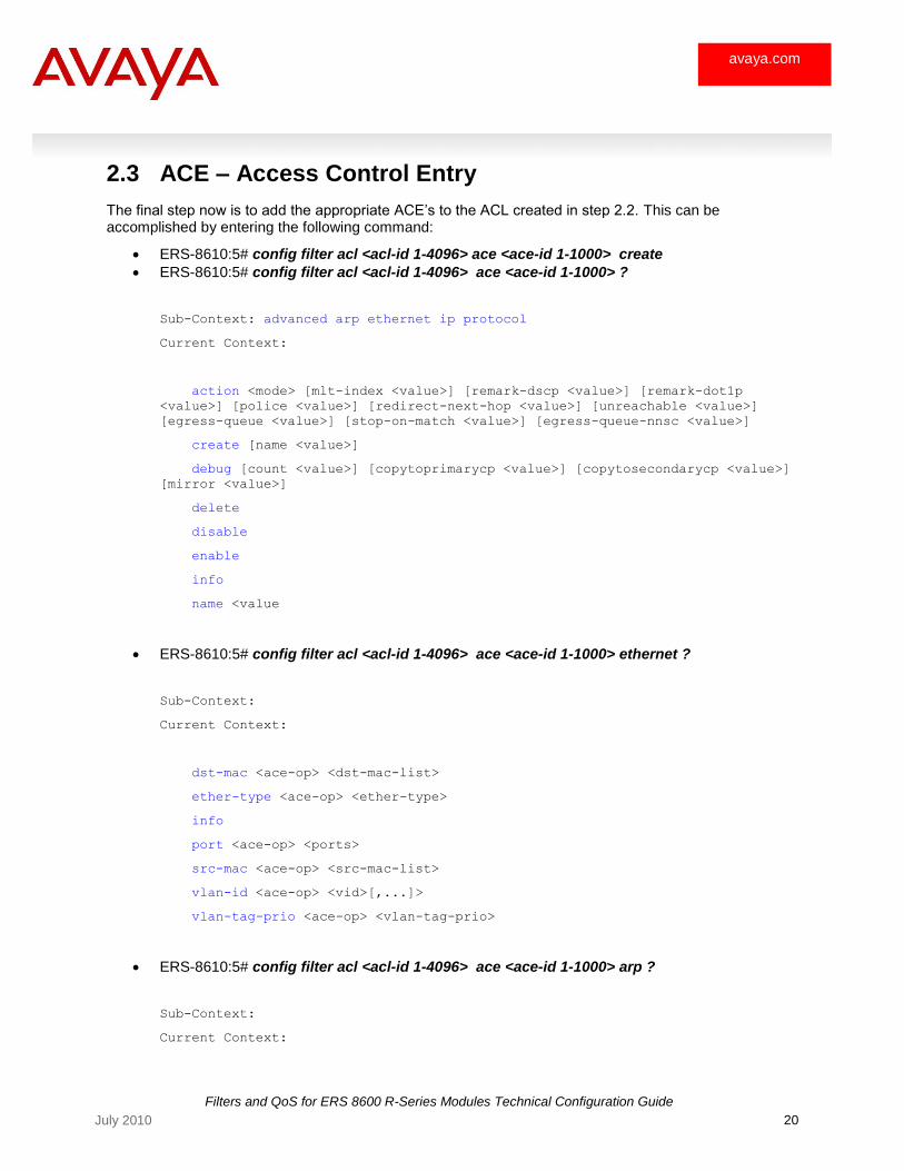
2.3 ACE – Access Control Entry
The final step now is to add the appropriate ACE‘s to the ACL created in step 2.2. This can be accomplished by entering the following command:
ERS-8610:5# config filter acl <acl-id 1-4096> ace <ace-id 1-1000> create
ERS-8610:5# config filter acl <acl-id 1-4096> ace <ace-id 1-1000> ?
Sub-Context: advanced arp ethernet ip protocol
Current Context:
action <mode> [mlt-index <value>] [remark-dscp <value>] [remark-dot1p
<value>] [police <value>] [redirect-next-hop <value>] [unreachable <value>]
[egress-queue <value>] [stop-on-match <value>] [egress-queue-nnsc <value>]
create [name <value>]
debug [count <value>] [copytoprimarycp <value>] [copytosecondarycp <value>]
[mirror <value>]
delete
disable
enable
info
name <value
ERS-8610:5# config filter acl <acl-id 1-4096> ace <ace-id 1-1000> ethernet ?
Sub-Context:
Current Context:
dst-mac <ace-op> <dst-mac-list>
ether-type <ace-op> <ether-type>
info
port <ace-op> <ports>
src-mac <ace-op> <src-mac-list>
vlan-id <ace-op> <vid>[,...]>
vlan-tag-prio <ace-op> <vlan-tag-prio>
ERS-8610:5# config filter acl <acl-id 1-4096> ace <ace-id 1-1000> arp ?
Sub-Context:
Current Context:
Filters and QoS for ERS 8600 R-Series Modules Technical Configuration Guide
21 July 2010
avaya.com
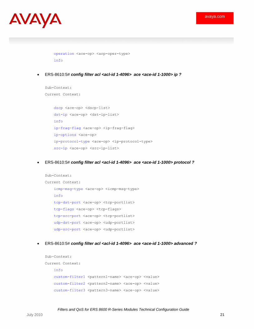
operation <ace-op> <arp-oper-type>
info
ERS-8610:5# config filter acl <acl-id 1-4096> ace <ace-id 1-1000> ip ?
Sub-Context:
Current Context:
dscp <ace-op> <dscp-list>
dst-ip <ace-op> <dst-ip-list>
info
ip-frag-flag <ace-op> <ip-frag-flag>
ip-options <ace-op>
ip-protocol-type <ace-op> <ip-protocol-type>
src-ip <ace-op> <src-ip-list>
ERS-8610:5# config filter acl <acl-id 1-4096> ace <ace-id 1-1000> protocol ?
Sub-Context:
Current Context:
icmp-msg-type <ace-op> <icmp-msg-type>
info
tcp-dst-port <ace-op> <tcp-portlist>
tcp-flags <ace-op> <tcp-flags>
tcp-src-port <ace-op> <tcp-portlist>
udp-dst-port <ace-op> <udp-portlist>
udp-src-port <ace-op> <udp-portlist>
ERS-8610:5# config filter acl <acl-id 1-4096> ace <ace-id 1-1000> advanced ?
Sub-Context:
Current Context:
info
custom-filter1 <pattern1-name> <ace-op> <value>
custom-filter2 <pattern2-name> <ace-op> <value>
custom-filter3 <pattern3-name> <ace-op> <value>
Filters and QoS for ERS 8600 R-Series Modules Technical Configuration Guide
22 July 2010
avaya.com
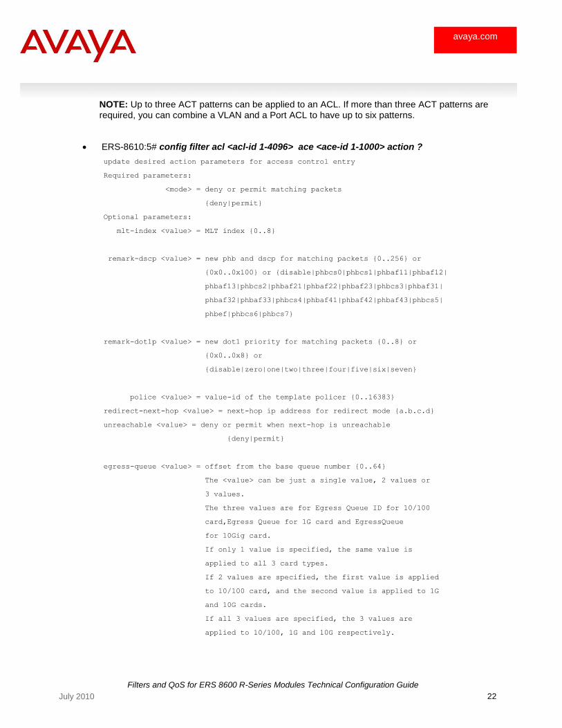
NOTE: Up to three ACT patterns can be applied to an ACL. If more than three ACT patterns are required, you can combine a VLAN and a Port ACL to have up to six patterns.
ERS-8610:5# config filter acl <acl-id 1-4096> ace <ace-id 1-1000> action ?
update desired action parameters for access control entry
Required parameters:
<mode> = deny or permit matching packets
{deny|permit}
Optional parameters:
mlt-index <value> = MLT index {0..8}
remark-dscp <value> = new phb and dscp for matching packets {0..256} or
{0x0..0x100} or {disable|phbcs0|phbcs1|phbaf11|phbaf12|
phbaf13|phbcs2|phbaf21|phbaf22|phbaf23|phbcs3|phbaf31|
phbaf32|phbaf33|phbcs4|phbaf41|phbaf42|phbaf43|phbcs5|
phbef|phbcs6|phbcs7}
remark-dot1p <value> = new dot1 priority for matching packets {0..8} or
{0x0..0x8} or
{disable|zero|one|two|three|four|five|six|seven}
police <value> = value-id of the template policer {0..16383}
redirect-next-hop <value> = next-hop ip address for redirect mode {a.b.c.d}
unreachable <value> = deny or permit when next-hop is unreachable
{deny|permit}
egress-queue <value> = offset from the base queue number {0..64}
The <value> can be just a single value, 2 values or
3 values.
The three values are for Egress Queue ID for 10/100
card,Egress Queue for 1G card and EgressQueue
for 10Gig card.
If only 1 value is specified, the same value is
applied to all 3 card types.
If 2 values are specified, the first value is applied
to 10/100 card, and the second value is applied to 1G
and 10G cards.
If all 3 values are specified, the 3 values are
applied to 10/100, 1G and 10G respectively.

Filters and QoS for ERS 8600 R-Series Modules Technical Configuration Guide
23 July 2010
avaya.com
stop-on-match <flag> = true/false for stop on match
egress-queue-nnsc <value> = Ace egress queue nnsc
{critical|custom|premium|platinum|gold|
silver|bronze|standard|disable}
Command syntax:
action <mode> [mlt-index <value>]
[remark-dscp <value>] [remark-dot1p <value>]
[police <value>] [redirect-next-hop <value>]
[unreachable <value>] [egress-queue <value>]
[stop-on-match <flag>] [egress-queue-nnsc <value>]
Where:
Field Description
AclId Specifies a unique identifier for the ACL entry in the range from 1-4096.
ActId Specifies a unique identifier for the ACT entry in the range from 1-4096.
ACE Advanced
Ace-op Specifies the operators for the ACE pattern used when an ACT pattern is configured. The custom-filter<1-3>-name selects the ACT pattern name configured.
<pattern1-name> = hex numeric string for user-defined field {string length 0..32}
Ace-op : operator for field match condition {eq|le|ge}
custom-filter1 <pattern1-name> <ace-op> <value>
ACE ARP, ACL
Operation Specifies the operator for ACE ARP operation. The eq value specifies an exact match.
Oper-type Specifies whether ACE ARP will be a request, arpRequest, or response, arpResponse.
ACE Ethernet, ACL
Dst-mac-list List of destination MAC addresses separated by a comma or a range of MAC
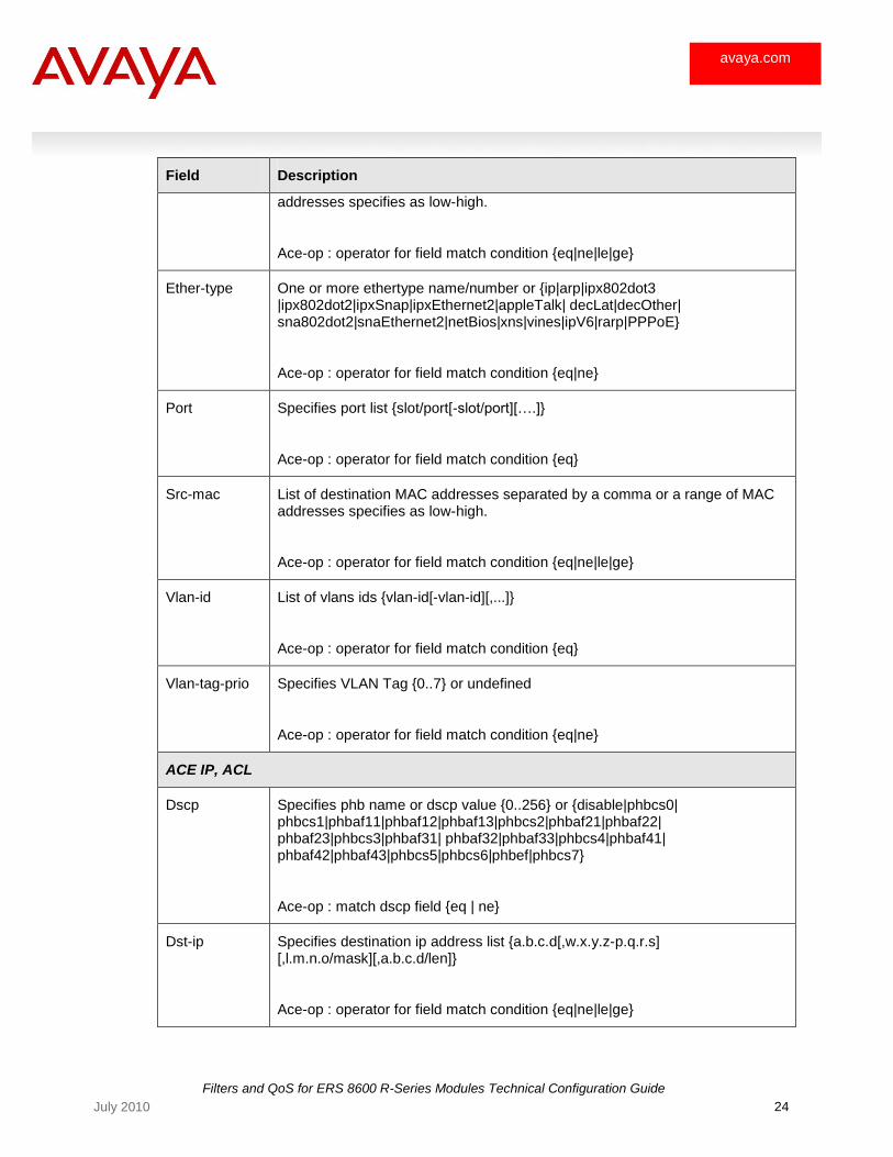
Filters and QoS for ERS 8600 R-Series Modules Technical Configuration Guide
24 July 2010
avaya.com
Field Description
addresses specifies as low-high.
Ace-op : operator for field match condition {eq|ne|le|ge}
Ether-type One or more ethertype name/number or {ip|arp|ipx802dot3 |ipx802dot2|ipxSnap|ipxEthernet2|appleTalk| decLat|decOther| sna802dot2|snaEthernet2|netBios|xns|vines|ipV6|rarp|PPPoE}
Ace-op : operator for field match condition {eq|ne}
Port Specifies port list {slot/port[-slot/port][….]}
Ace-op : operator for field match condition {eq}
Src-mac List of destination MAC addresses separated by a comma or a range of MAC addresses specifies as low-high.
Ace-op : operator for field match condition {eq|ne|le|ge}
Vlan-id List of vlans ids {vlan-id[-vlan-id][,...]}
Ace-op : operator for field match condition {eq}
Vlan-tag-prio Specifies VLAN Tag {0..7} or undefined
Ace-op : operator for field match condition {eq|ne}
ACE IP, ACL
Dscp Specifies phb name or dscp value {0..256} or {disable|phbcs0| phbcs1|phbaf11|phbaf12|phbaf13|phbcs2|phbaf21|phbaf22| phbaf23|phbcs3|phbaf31| phbaf32|phbaf33|phbcs4|phbaf41| phbaf42|phbaf43|phbcs5|phbcs6|phbef|phbcs7}
Ace-op : match dscp field {eq | ne}
Dst-ip Specifies destination ip address list {a.b.c.d[,w.x.y.z-p.q.r.s] [,l.m.n.o/mask][,a.b.c.d/len]}
Ace-op : operator for field match condition {eq|ne|le|ge}
Filters and QoS for ERS 8600 R-Series Modules Technical Configuration Guide
25 July 2010
avaya.com
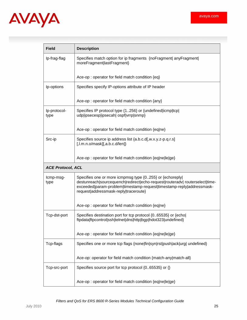
Field Description
Ip-frag-flag Specifies match option for ip fragments {noFragment| anyFragment| moreFragment|lastFragment}
Ace-op : operator for field match condition {eq}
Ip-options Specifies specify IP-options attribute of IP header
Ace-op : operator for field match condition {any}
Ip-protocol-type
Specifies IP protocol type {1..256} or {undefined|icmp|tcp| udp|ipsecesp|ipsecah| ospf|vrrp|snmp}
Ace-op : operator for field match condition {eq|ne}
Src-ip Specifies source ip address list {a.b.c.d[,w.x.y.z-p.q.r.s] [,l.m.n.o/mask][,a.b.c.d/len]}
Ace-op : operator for field match condition {eq|ne|le|ge}
ACE Protocol, ACL
Icmp-msg-type
Specifies one or more icmpmsg type {0..255} or {echoreply| destunreach|sourcequench|redirect|echo-request|routeradv| routerselect|time-exceeded|param-problem|timestamp-request|timestamp-reply|addressmask-request|addressmask-reply|traceroute}
Ace-op : operator for field match condition {eq|ne}
Tcp-dst-port Specifies destination port for tcp protocol {0..65535} or {echo| ftpdata|ftpcontrol|ssh|telnet|dns|http|bgp|hdot323|undefined}
Ace-op : operator for field match condition {eq|ne|le|ge}
Tcp-flags Specifies one or more tcp flags {none|fin|syn|rst|push|ack|urg| undefined}
Ace-op: operator for field match condition {match-any|match-all}
Tcp-src-port Specifies source port for tcp protocol {0..65535} or {}
Ace-op : operator for field match condition {eq|ne|le|ge}
Filters and QoS for ERS 8600 R-Series Modules Technical Configuration Guide
26 July 2010
avaya.com
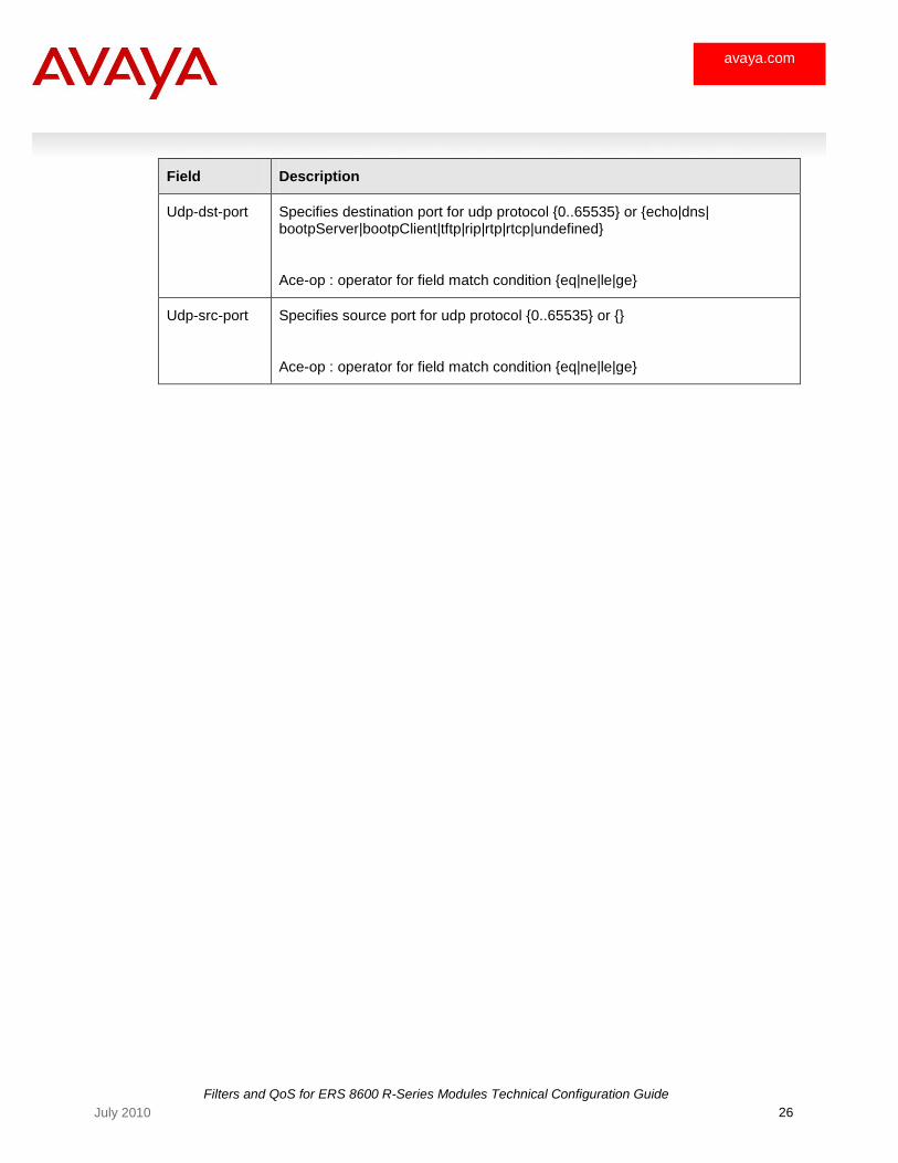
Field Description
Udp-dst-port Specifies destination port for udp protocol {0..65535} or {echo|dns| bootpServer|bootpClient|tftp|rip|rtp|rtcp|undefined}
Ace-op : operator for field match condition {eq|ne|le|ge}
Udp-src-port Specifies source port for udp protocol {0..65535} or {}
Ace-op : operator for field match condition {eq|ne|le|ge}
Filters and QoS for ERS 8600 R-Series Modules Technical Configuration Guide
27 July 2010
avaya.com
3. R-Module Queuing
3.1 Overview
R-modules, by default, have two reserved and pre-configured egress queue templates based on Ayaya Data Solutions Service Class (ADSSC) – please see http://www.nortelnetworks.com/products/02/bstk/switches/bps/collateral/56058.25_022403.pdf. In the 4.0 release, one template has 8 queues while the other has up to 64 queues. In addition to this, a user can add individual egress queue templates to any port. Overall, the following explains the queue options pertaining to the type of I/O module used:
I/O modules with 1 egress port per LANE can utilize all 640 elementary queues. In the 4.0 software release, 64 out 640 queues per 10GE port are used. This would apply to the 8683XLR (3-port 10GE) and 8683XZR (3-port 10GE).
I/O modules with more than 1 port, but no more than 10 ports per lane can utilize up to 64 elementary queues per port. This would apply to the 8630GBR (30-port GE) I/O module.
I/O modules with more than 10 ports per lane support 8 elementary queues per port. This would apply to the 8648GTR (48-port 10/100/1000) I/O module.
Each queue within the egress queue is further broken down to one of three queue styles.
High Priority Group
o Queues in this group have the highest precedence over other queues in other groups and are serviced first
o Strict priority is used o Queues belonging to this group are numbered from queue index 63 and decrements o Any packet in queue 63 will be serviced first followed by queue 62 in this order o On trusted ports, incoming packets with 802.1p = 6 or DSCP CS5/EF are placed in queue 62
by default o A maximum rate can be configured on a high priority queue to avoid bandwidth monopoly
Balanced Queuing Group (Weighted Round Robin)
o Balanced queues are serviced second after traffic from the high priority queues are serviced o Queues belonging to the balanced group are serviced by a weighted round robin scheduler o Each balanced queue has a minimum rate and maximum rate where the minimum rate
provide a guarantee bandwidth while the maximum rate provide a maximum rate if no data is serviced on other queues
o The sum of all minimum rates configured on all queues cannot exceed 100% - line rate of the port
o Minimum rates are not applicable to High Priority Groups or Low Priority Groups
Low Priority Group
o Queues belonging to the low priority group are serviced last as-is or best effort o There is no minimum rate associated with a low priority group
Please see section 3.2 showing the egress queue mappings.
Filters and QoS for ERS 8600 R-Series Modules Technical Configuration Guide
28 July 2010
avaya.com
Feedback Output Queueing (FOQ)
ERS 8600 Release 4.0 reports congestion for individual egress queues. Feedback output queueing (FOQ) notifies the ingress ports of congestion ahead so that the switch fabric doesn‘t waste resources forwarding packets or cells that will probably get dropped. FOQ avoids congestion and packet drops indiscriminate of QoS flows.
We recommend that you enable FOQ in a system with only R modules. You must enable R-mode to use FOQ. FOQ is not supported in a system with a mix of modules (R modules and pre-E, E- or M-modules). Please see section 5.3 regarding R-mode.
3.2 Default Packet QoS to Egress Queue Mapping
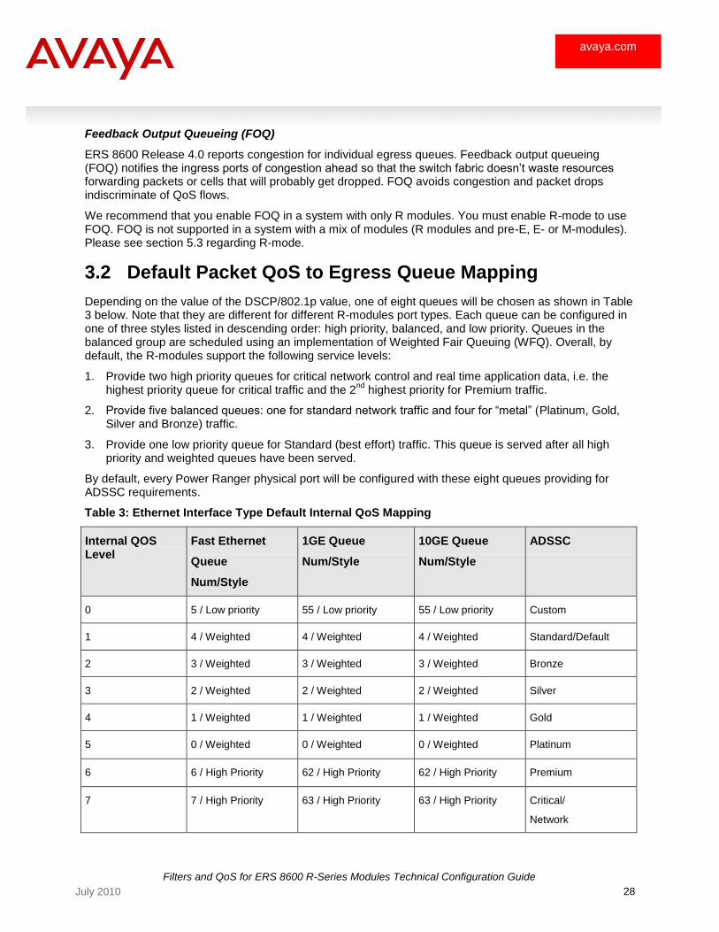
Depending on the value of the DSCP/802.1p value, one of eight queues will be chosen as shown in Table 3 below. Note that they are different for different R-modules port types. Each queue can be configured in one of three styles listed in descending order: high priority, balanced, and low priority. Queues in the balanced group are scheduled using an implementation of Weighted Fair Queuing (WFQ). Overall, by default, the R-modules support the following service levels:
1. Provide two high priority queues for critical network control and real time application data, i.e. the highest priority queue for critical traffic and the 2
nd highest priority for Premium traffic.
2. Provide five balanced queues: one for standard network traffic and four for ―metal‖ (Platinum, Gold, Silver and Bronze) traffic.
3. Provide one low priority queue for Standard (best effort) traffic. This queue is served after all high priority and weighted queues have been served.
By default, every Power Ranger physical port will be configured with these eight queues providing for ADSSC requirements.
Table 3: Ethernet Interface Type Default Internal QoS Mapping
Internal QOS Level
Fast Ethernet
Queue
Num/Style
1GE Queue
Num/Style
10GE Queue
Num/Style
ADSSC
0 5 / Low priority 55 / Low priority 55 / Low priority Custom
1 4 / Weighted 4 / Weighted 4 / Weighted Standard/Default
2 3 / Weighted 3 / Weighted 3 / Weighted Bronze
3 2 / Weighted 2 / Weighted 2 / Weighted Silver
4 1 / Weighted 1 / Weighted 1 / Weighted Gold
5 0 / Weighted 0 / Weighted 0 / Weighted Platinum
6 6 / High Priority 62 / High Priority 62 / High Priority Premium
7 7 / High Priority 63 / High Priority 63 / High Priority Critical/
Network
Filters and QoS for ERS 8600 R-Series Modules Technical Configuration Guide
29 July 2010
avaya.com
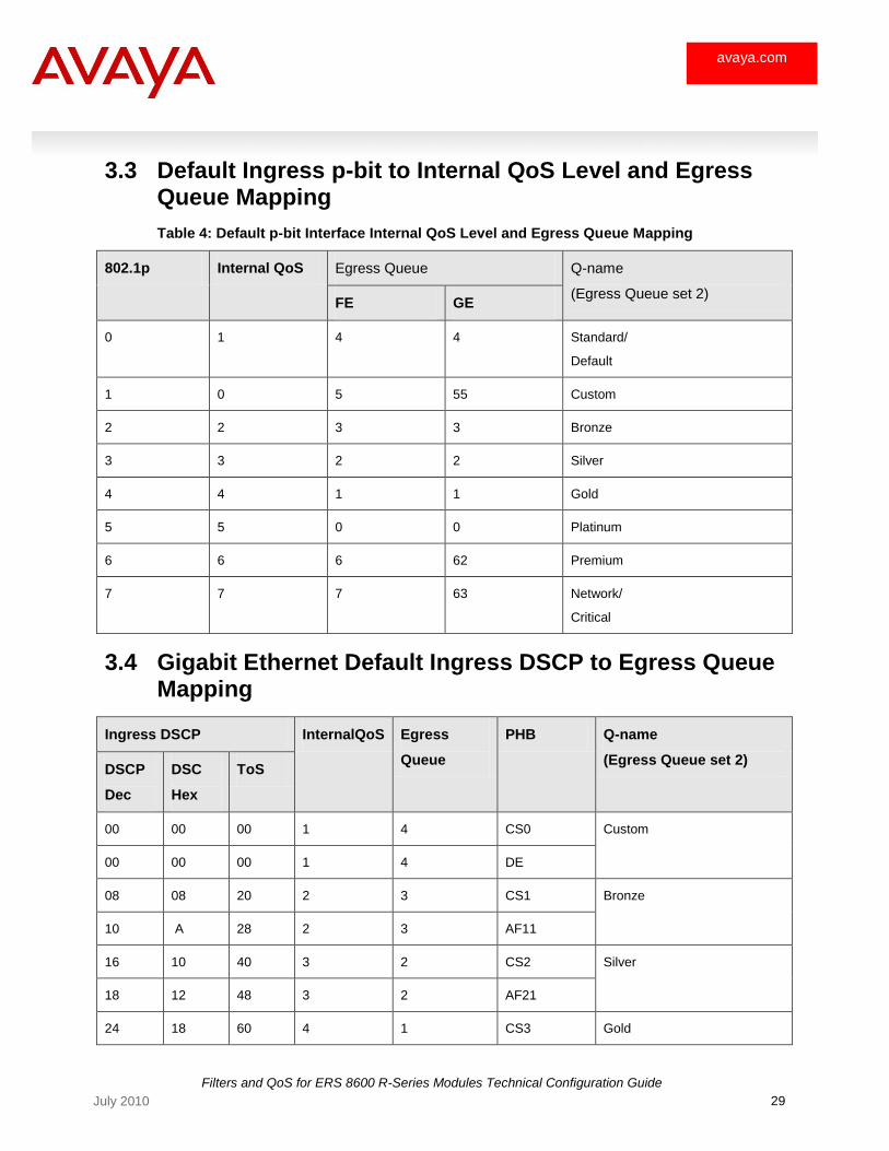
3.3 Default Ingress p-bit to Internal QoS Level and Egress Queue Mapping
Table 4: Default p-bit Interface Internal QoS Level and Egress Queue Mapping
802.1p Internal QoS Egress Queue Q-name
(Egress Queue set 2) FE GE
0 1 4 4 Standard/
Default
1 0 5 55 Custom
2 2 3 3 Bronze
3 3 2 2 Silver
4 4 1 1 Gold
5 5 0 0 Platinum
6 6 6 62 Premium
7 7 7 63 Network/
Critical
3.4 Gigabit Ethernet Default Ingress DSCP to Egress Queue Mapping
Ingress DSCP InternalQoS Egress
Queue
PHB Q-name
(Egress Queue set 2) DSCP
Dec
DSC
Hex
ToS
00 00 00 1 4 CS0 Custom
00 00 00 1 4 DE
08 08 20 2 3 CS1 Bronze
10 A 28 2 3 AF11
16 10 40 3 2 CS2 Silver
18 12 48 3 2 AF21
24 18 60 4 1 CS3 Gold
Filters and QoS for ERS 8600 R-Series Modules Technical Configuration Guide
30 July 2010
avaya.com
26 1A 68 4 1 AF31
32 20 80 5 0 CS4 Platinum
34 22 88 5 0 AF41
40 28 A0 6 62 CS5 Premium
46 2E B8 6 62 EF
48 30 C0 7 63 CS6 Network/
Critical 56 38 E0 7 63 CS7
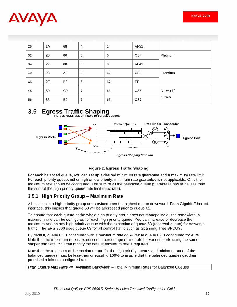
3.5 Egress Traffic Shaping
Figure 2: Egress Traffic Shaping
For each balanced queue, you can set up a desired minimum rate guarantee and a maximum rate limit. For each priority queue, either high or low priority, minimum rate guarantee is not applicable. Only the maximum rate should be configured. The sum of all the balanced queue guarantees has to be less than the sum of the high priority queue rate limit (max rate).
3.5.1 High Priority Group – Maximum Rate
All packets in a high priority group are serviced from the highest queue downward. For a Gigabit Ethernet interface, this implies that queue 63 will be addressed prior to queue 62.
To ensure that each queue or the whole high priority group does not monopolize all the bandwidth, a maximum rate can be configured for each high priority queue. You can increase or decrease the maximum rate on any high priority queue with the exception of queue 63 (reserved queue) for networks traffic. The ERS 8600 uses queue 63 for all control traffic such as Spanning Tree BPDU‘s.
By default, queue 63 is configured with a maximum rate of 5% while queue 62 is configured for 45%. Note that the maximum rate is expressed in percentage of line rate for various ports using the same shaper template. You can modify the default maximum rate if required.
Note that the total sum of the maximum rate for the high priority queues and minimum rated of the balanced queues must be less-than or equal to 100% to ensure that the balanced queues get their promised minimum configured rate.
High Queue Max Rate <= [Available Bandwidth – Total Minimum Rates for Balanced Queues
Ingress Ports Egress Port
Rate limiter Packet Queues
Egress Shaping function
Scheduler
Ingress ACLs assign flows to egress queues
Filters and QoS for ERS 8600 R-Series Modules Technical Configuration Guide
31 July 2010
avaya.com
3.5.2 Balanced Priority Group – Minimum and Maximum Rates
Queues belonging to the balanced group are serviced by a weighted round robin scheduler. Each queue in the balanced group is assigned a minimum rate and a maximum rate. The minimum rate is a guarantee to provide at least the percentage of bandwidth share configured for the queue. For example, on a Gigabit Ethernet link, if the queue is configured for 10% minimum rate, the queue will guarantee to get a 100MB from the total available bandwidth. The rate on a particular queue can go up the maximum rate configured providing there is no traffic to be serviced on the other queues.
3.5.3 Queue Size
Up to 32K memory pages are supported per LANE. Hence, up to 32K memory pages are supported per 10GE port or 10 x 1GE ports. Please see Table 4, Default QoS to Egress Queue Mapping, regarding the default queue size in pages per egress queue. The default setting can be changed by using the commands shown in section 3.5.2.
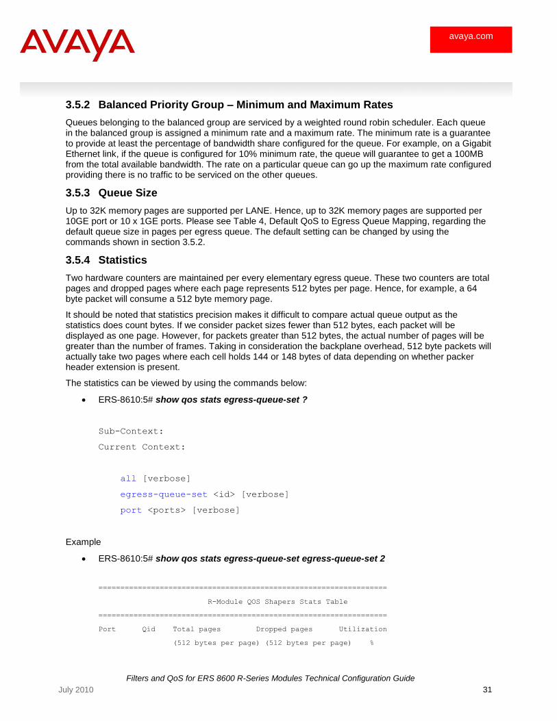
3.5.4 Statistics
Two hardware counters are maintained per every elementary egress queue. These two counters are total pages and dropped pages where each page represents 512 bytes per page. Hence, for example, a 64 byte packet will consume a 512 byte memory page.
It should be noted that statistics precision makes it difficult to compare actual queue output as the statistics does count bytes. If we consider packet sizes fewer than 512 bytes, each packet will be displayed as one page. However, for packets greater than 512 bytes, the actual number of pages will be greater than the number of frames. Taking in consideration the backplane overhead, 512 byte packets will actually take two pages where each cell holds 144 or 148 bytes of data depending on whether packer header extension is present.
The statistics can be viewed by using the commands below:
ERS-8610:5# show qos stats egress-queue-set ?
Sub-Context:
Current Context:
all [verbose]
egress-queue-set <id> [verbose]
port <ports> [verbose]
Example
ERS-8610:5# show qos stats egress-queue-set egress-queue-set 2
==================================================================
R-Module QOS Shapers Stats Table
==================================================================
Port Qid Total pages Dropped pages Utilization
(512 bytes per page) (512 bytes per page) %
Filters and QoS for ERS 8600 R-Series Modules Technical Configuration Guide
32 July 2010
avaya.com
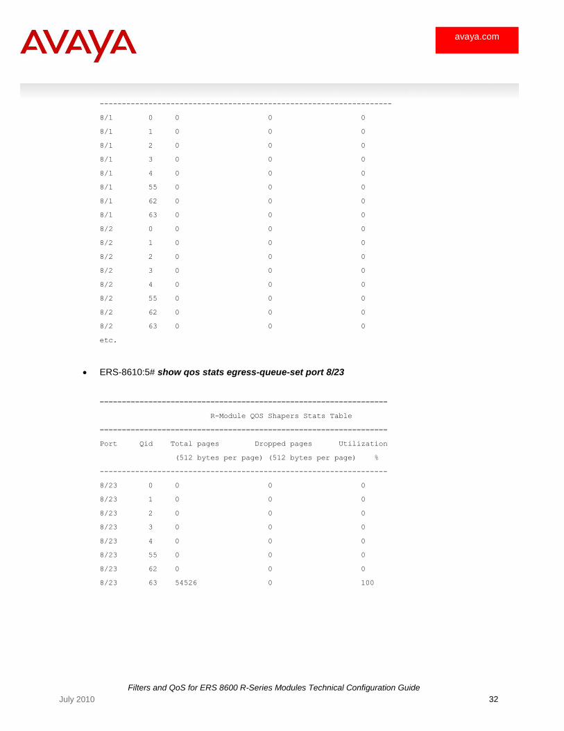
------------------------------------------------------------------
8/1 0 0 0 0
8/1 1 0 0 0
8/1 2 0 0 0
8/1 3 0 0 0
8/1 4 0 0 0
8/1 55 0 0 0
8/1 62 0 0 0
8/1 63 0 0 0
8/2 0 0 0 0
8/2 1 0 0 0
8/2 2 0 0 0
8/2 3 0 0 0
8/2 4 0 0 0
8/2 55 0 0 0
8/2 62 0 0 0
8/2 63 0 0 0
etc.
ERS-8610:5# show qos stats egress-queue-set port 8/23
=================================================================
R-Module QOS Shapers Stats Table
=================================================================
Port Qid Total pages Dropped pages Utilization
(512 bytes per page) (512 bytes per page) %
-----------------------------------------------------------------
8/23 0 0 0 0
8/23 1 0 0 0
8/23 2 0 0 0
8/23 3 0 0 0
8/23 4 0 0 0
8/23 55 0 0 0
8/23 62 0 0 0
8/23 63 54526 0 100
Filters and QoS for ERS 8600 R-Series Modules Technical Configuration Guide
33 July 2010
avaya.com
3.6 Queue Set Configuration Commands
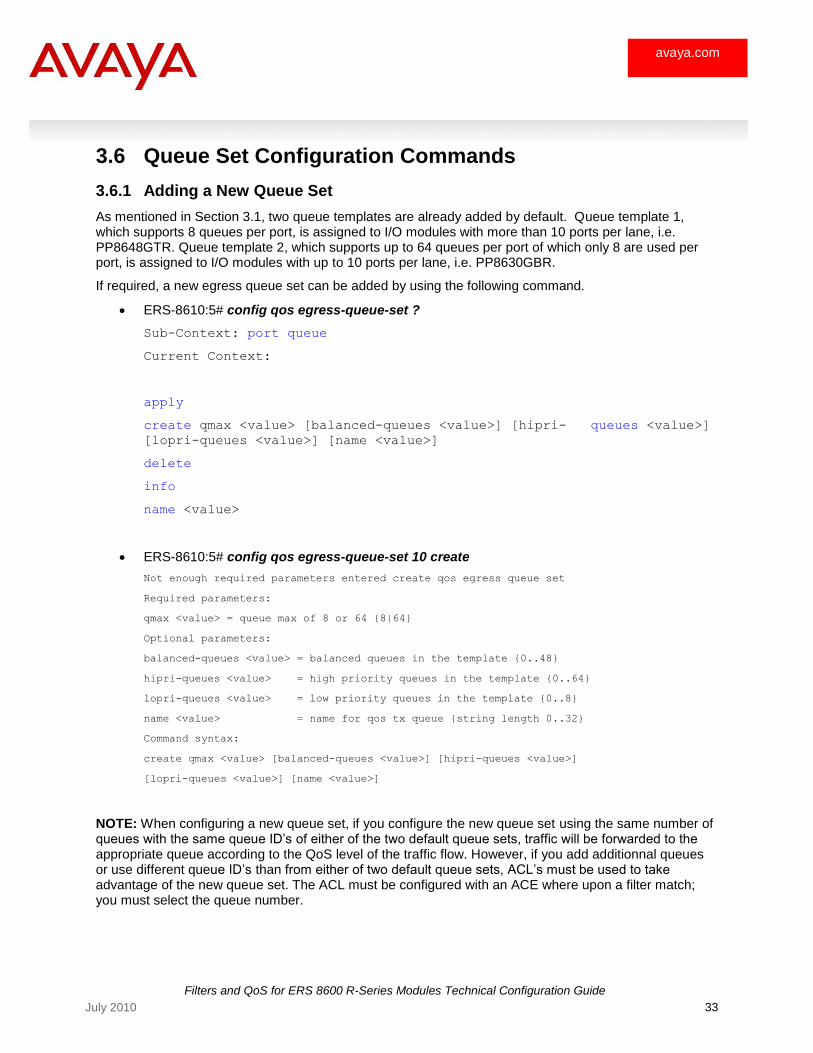
3.6.1 Adding a New Queue Set
As mentioned in Section 3.1, two queue templates are already added by default. Queue template 1, which supports 8 queues per port, is assigned to I/O modules with more than 10 ports per lane, i.e. PP8648GTR. Queue template 2, which supports up to 64 queues per port of which only 8 are used per port, is assigned to I/O modules with up to 10 ports per lane, i.e. PP8630GBR.
If required, a new egress queue set can be added by using the following command.
ERS-8610:5# config qos egress-queue-set ?
Sub-Context: port queue
Current Context:
apply
create qmax <value> [balanced-queues <value>] [hipri- queues <value>]
[lopri-queues <value>] [name <value>]
delete
info
name <value>
ERS-8610:5# config qos egress-queue-set 10 create
Not enough required parameters entered create qos egress queue set
Required parameters:
qmax <value> = queue max of 8 or 64 {8|64}
Optional parameters:
balanced-queues <value> = balanced queues in the template {0..48}
hipri-queues <value> = high priority queues in the template {0..64}
lopri-queues <value> = low priority queues in the template {0..8}
name <value> = name for qos tx queue {string length 0..32}
Command syntax:
create qmax <value> [balanced-queues <value>] [hipri-queues <value>]
[lopri-queues <value>] [name <value>]
NOTE: When configuring a new queue set, if you configure the new queue set using the same number of queues with the same queue ID‘s of either of the two default queue sets, traffic will be forwarded to the appropriate queue according to the QoS level of the traffic flow. However, if you add additionnal queues or use different queue ID‘s than from either of two default queue sets, ACL‘s must be used to take advantage of the new queue set. The ACL must be configured with an ACE where upon a filter match; you must select the queue number.
Filters and QoS for ERS 8600 R-Series Modules Technical Configuration Guide
34 July 2010
avaya.com
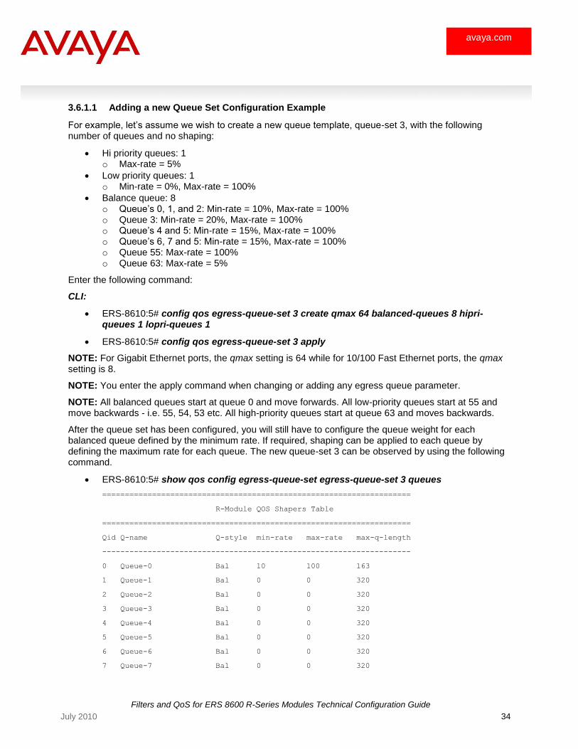
3.6.1.1 Adding a new Queue Set Configuration Example
For example, let‘s assume we wish to create a new queue template, queue-set 3, with the following number of queues and no shaping:
Hi priority queues: 1 o Max-rate = 5%
Low priority queues: 1 o Min-rate = 0%, Max-rate = 100%
Balance queue: 8 o Queue‘s 0, 1, and 2: Min-rate = 10%, Max-rate = 100% o Queue 3: Min-rate = 20%, Max-rate = 100% o Queue‘s 4 and 5: Min-rate = 15%, Max-rate = 100% o Queue‘s 6, 7 and 5: Min-rate = 15%, Max-rate = 100% o Queue 55: Max-rate = 100% o Queue 63: Max-rate = 5%
Enter the following command:
CLI:
ERS-8610:5# config qos egress-queue-set 3 create qmax 64 balanced-queues 8 hipri-queues 1 lopri-queues 1
ERS-8610:5# config qos egress-queue-set 3 apply
NOTE: For Gigabit Ethernet ports, the qmax setting is 64 while for 10/100 Fast Ethernet ports, the qmax setting is 8.
NOTE: You enter the apply command when changing or adding any egress queue parameter.
NOTE: All balanced queues start at queue 0 and move forwards. All low-priority queues start at 55 and move backwards - i.e. 55, 54, 53 etc. All high-priority queues start at queue 63 and moves backwards.
After the queue set has been configured, you will still have to configure the queue weight for each balanced queue defined by the minimum rate. If required, shaping can be applied to each queue by defining the maximum rate for each queue. The new queue-set 3 can be observed by using the following command.
ERS-8610:5# show qos config egress-queue-set egress-queue-set 3 queues
====================================================================
R-Module QOS Shapers Table
====================================================================
Qid Q-name Q-style min-rate max-rate max-q-length
--------------------------------------------------------------------
0 Queue-0 Bal 10 100 163
1 Queue-1 Bal 0 0 320
2 Queue-2 Bal 0 0 320
3 Queue-3 Bal 0 0 320
4 Queue-4 Bal 0 0 320
5 Queue-5 Bal 0 0 320
6 Queue-6 Bal 0 0 320
7 Queue-7 Bal 0 0 320
Filters and QoS for ERS 8600 R-Series Modules Technical Configuration Guide
35 July 2010
avaya.com
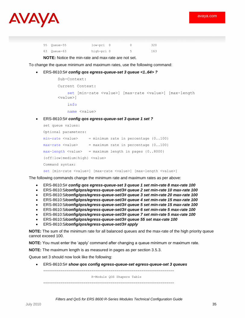
55 Queue-55 low-pri 0 0 320
63 Queue-63 high-pri 0 5 163
NOTE: Notice the min-rate and max-rate are not set.
To change the queue minimum and maximum rates, use the following command:
ERS-8610:5# config qos egress-queue-set 3 queue <1..64> ?
Sub-Context:
Current Context:
set [min-rate <value>] [max-rate <value>] [max-length
<value>]
info
name <value>
ERS-8610:5# config qos egress-queue-set 3 queue 1 set ?
set queue values:
Optional parameters:
min-rate <value> = minimum rate in percentage {0..100}
max-rate <value> = maximum rate in percentage {0..100}
max-length <value> = maximum length in pages {0..8000}
{off|low|medium|high} <value>
Command syntax:
set [min-rate <value>] [max-rate <value>] [max-length <value>]
The following commands change the minimum rate and maximum rates as per above:
ERS-8610:5# config qos egress-queue-set 3 queue 1 set min-rate 8 max-rate 100
ERS-8610:5/config/qos/egress-queue-set/3# queue 2 set min-rate 10 max-rate 100
ERS-8610:5/config/qos/egress-queue-set/3# queue 3 set min-rate 20 max-rate 100
ERS-8610:5/config/qos/egress-queue-set/3# queue 4 set min-rate 15 max-rate 100
ERS-8610:5/config/qos/egress-queue-set/3# queue 5 set min-rate 15 max-rate 100
ERS-8610:5/config/qos/egress-queue-set/3# queue 6 set min-rate 5 max-rate 100
ERS-8610:5/config/qos/egress-queue-set/3# queue 7 set min-rate 5 max-rate 100
ERS-8610:5/config/qos/egress-queue-set/3# queue 55 set max-rate 100
ERS-8610:5/config/qos/egress-queue-set/3# apply
NOTE: The sum of the minimum rate for all balanced queues and the max-rate of the high priority queue cannot exceed 100.
NOTE: You must enter the ‗apply‘ command after changing a queue minimum or maximum rate.
NOTE: The maximum length is as measured in pages as per section 3.5.3.
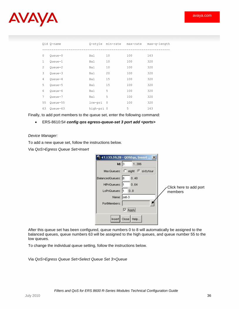
Queue set 3 should now look like the following:
ERS-8610:5# show qos config egress-queue-set egress-queue-set 3 queues
====================================================================
R-Module QOS Shapers Table
====================================================================
Filters and QoS for ERS 8600 R-Series Modules Technical Configuration Guide
36 July 2010
avaya.com
Qid Q-name Q-style min-rate max-rate max-q-length
--------------------------------------------------------------------
0 Queue-0 Bal 10 100 163
1 Queue-1 Bal 10 100 320
2 Queue-2 Bal 10 100 320
3 Queue-3 Bal 20 100 320
4 Queue-4 Bal 15 100 320
5 Queue-5 Bal 15 100 320
6 Queue-6 Bal 5 100 320
7 Queue-7 Bal 5 100 320
55 Queue-55 low-pri 0 100 320
63 Queue-63 high-pri 0 5 163
Finally, to add port members to the queue set, enter the following command:
ERS-8610:5# config qos egress-queue-set 3 port add <ports>
Device Manager:
To add a new queue set, follow the instructions below.
Via QoS>Egress Queue Set>Insert
After this queue set has been configured, queue numbers 0 to 8 will automatically be assigned to the balanced queues, queue numbers 63 will be assigned to the high queues, and queue number 55 to the low queues.
To change the individual queue setting, follow the instructions below.
Via QoS>Egress Queue Set>Select Queue Set 3>Queue
Click here to add port members
Filters and QoS for ERS 8600 R-Series Modules Technical Configuration Guide
37 July 2010
avaya.com
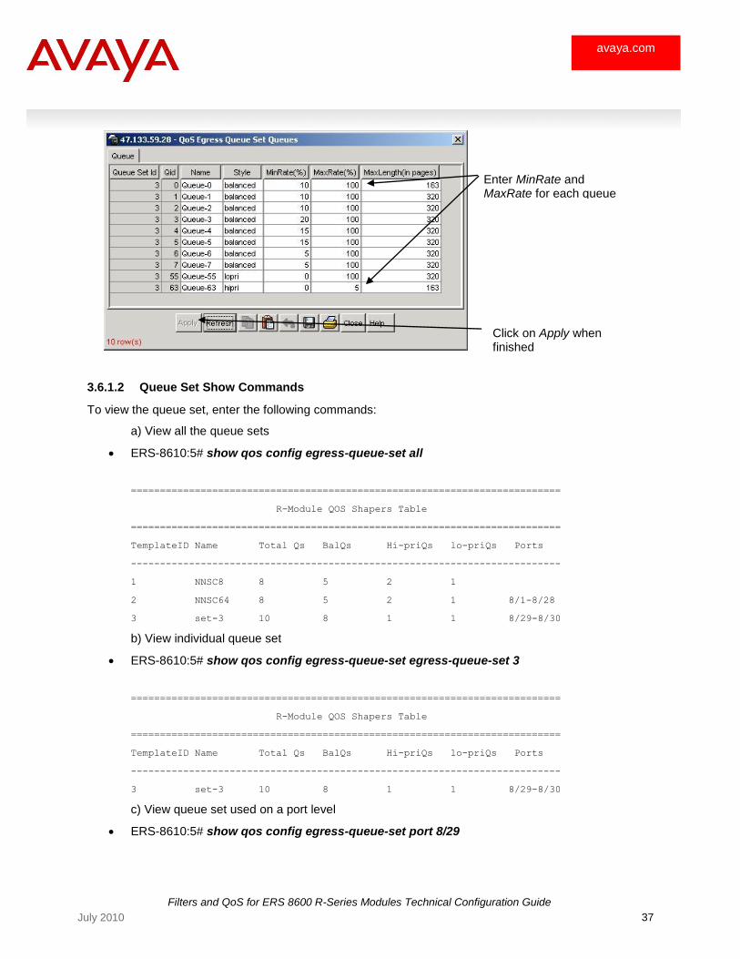
3.6.1.2 Queue Set Show Commands
To view the queue set, enter the following commands:
a) View all the queue sets
ERS-8610:5# show qos config egress-queue-set all
==========================================================================
R-Module QOS Shapers Table
==========================================================================
TemplateID Name Total Qs BalQs Hi-priQs lo-priQs Ports
--------------------------------------------------------------------------
1 NNSC8 8 5 2 1
2 NNSC64 8 5 2 1 8/1-8/28
3 set-3 10 8 1 1 8/29-8/30
b) View individual queue set
ERS-8610:5# show qos config egress-queue-set egress-queue-set 3
==========================================================================
R-Module QOS Shapers Table
==========================================================================
TemplateID Name Total Qs BalQs Hi-priQs lo-priQs Ports
--------------------------------------------------------------------------
3 set-3 10 8 1 1 8/29-8/30
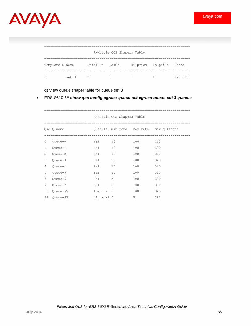
c) View queue set used on a port level
ERS-8610:5# show qos config egress-queue-set port 8/29
Enter MinRate and MaxRate for each queue
Click on Apply when finished
Filters and QoS for ERS 8600 R-Series Modules Technical Configuration Guide
38 July 2010
avaya.com
==========================================================================
R-Module QOS Shapers Table
==========================================================================
TemplateID Name Total Qs BalQs Hi-priQs lo-priQs Ports
--------------------------------------------------------------------------
3 set-3 10 8 1 1 8/29-8/30
d) View queue shaper table for queue set 3
ERS-8610:5# show qos config egress-queue-set egress-queue-set 3 queues
==========================================================================
R-Module QOS Shapers Table
==========================================================================
Qid Q-name Q-style min-rate max-rate max-q-length
--------------------------------------------------------------------------
0 Queue-0 Bal 10 100 163
1 Queue-1 Bal 10 100 320
2 Queue-2 Bal 10 100 320
3 Queue-3 Bal 20 100 320
4 Queue-4 Bal 15 100 320
5 Queue-5 Bal 15 100 320
6 Queue-6 Bal 5 100 320
7 Queue-7 Bal 5 100 320
55 Queue-55 low-pri 0 100 320
63 Queue-63 high-pri 0 5 163
Filters and QoS for ERS 8600 R-Series Modules Technical Configuration Guide
39 July 2010
avaya.com
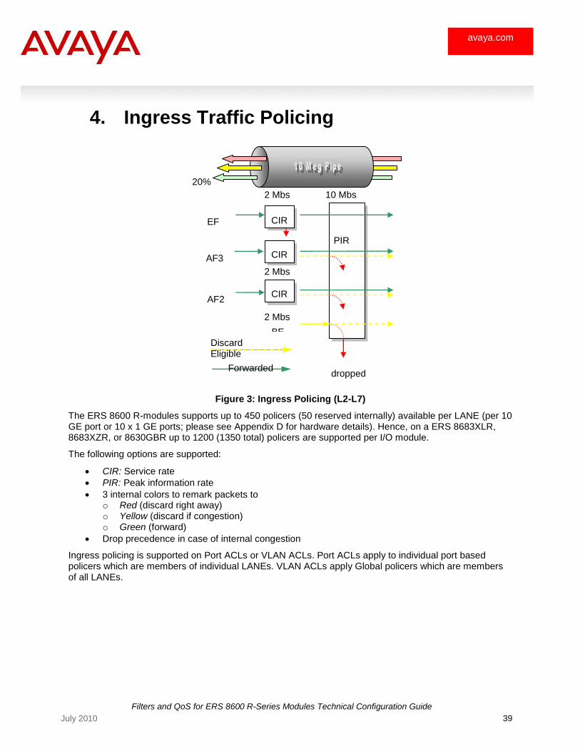
4. Ingress Traffic Policing
Figure 3: Ingress Policing (L2-L7)
The ERS 8600 R-modules supports up to 450 policers (50 reserved internally) available per LANE (per 10 GE port or 10 x 1 GE ports; please see Appendix D for hardware details). Hence, on a ERS 8683XLR, 8683XZR, or 8630GBR up to 1200 (1350 total) policers are supported per I/O module.
The following options are supported:
CIR: Service rate
PIR: Peak information rate
3 internal colors to remark packets to o Red (discard right away) o Yellow (discard if congestion) o Green (forward)
Drop precedence in case of internal congestion
Ingress policing is supported on Port ACLs or VLAN ACLs. Port ACLs apply to individual port based policers which are members of individual LANEs. VLAN ACLs apply Global policers which are members of all LANEs.
20%
EF
AF3
BE
AF2 CIR
PIR
2 Mbs 10 Mbs
2 Mbs
2 Mbs
Discard Eligible
Forwarded dropped
CIR
CIR
Filters and QoS for ERS 8600 R-Series Modules Technical Configuration Guide
40 July 2010
avaya.com
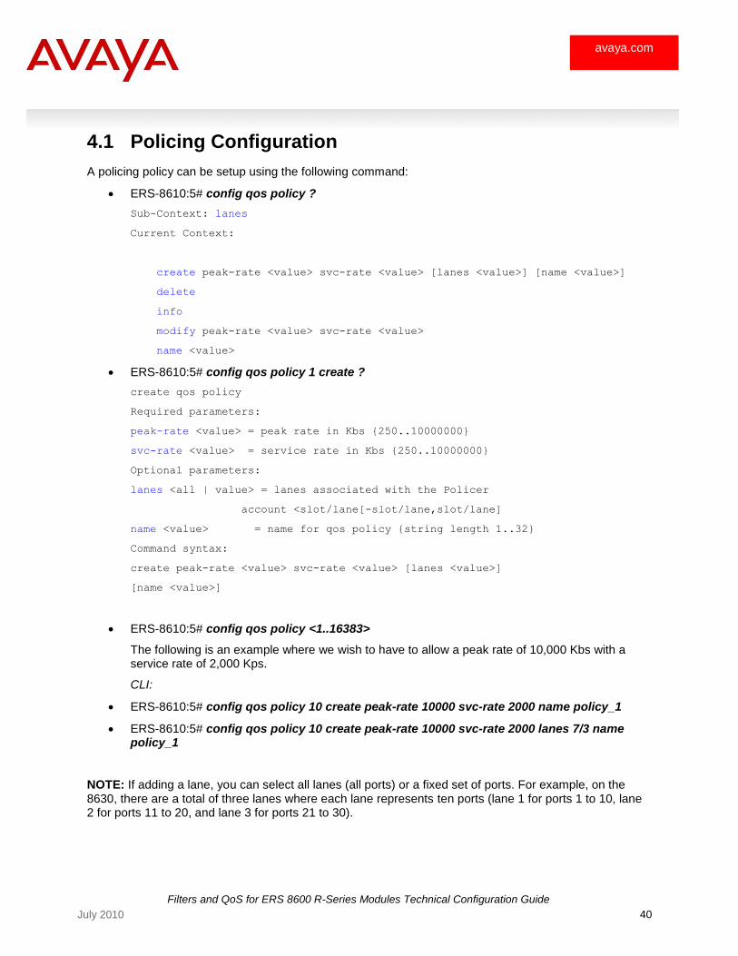
4.1 Policing Configuration
A policing policy can be setup using the following command:
ERS-8610:5# config qos policy ?
Sub-Context: lanes
Current Context:
create peak-rate <value> svc-rate <value> [lanes <value>] [name <value>]
delete
info
modify peak-rate <value> svc-rate <value>
name <value>
ERS-8610:5# config qos policy 1 create ?
create qos policy
Required parameters:
peak-rate <value> = peak rate in Kbs {250..10000000}
svc-rate <value> = service rate in Kbs {250..10000000}
Optional parameters:
lanes <all | value> = lanes associated with the Policer
account <slot/lane[-slot/lane,slot/lane]
name <value> = name for qos policy {string length 1..32}
Command syntax:
create peak-rate <value> svc-rate <value> [lanes <value>]
[name <value>]
ERS-8610:5# config qos policy <1..16383>
The following is an example where we wish to have to allow a peak rate of 10,000 Kbs with a service rate of 2,000 Kps.
CLI:
ERS-8610:5# config qos policy 10 create peak-rate 10000 svc-rate 2000 name policy_1
ERS-8610:5# config qos policy 10 create peak-rate 10000 svc-rate 2000 lanes 7/3 name policy_1
NOTE: If adding a lane, you can select all lanes (all ports) or a fixed set of ports. For example, on the 8630, there are a total of three lanes where each lane represents ten ports (lane 1 for ports 1 to 10, lane 2 for ports 11 to 20, and lane 3 for ports 21 to 30).

Filters and QoS for ERS 8600 R-Series Modules Technical Configuration Guide
41 July 2010
avaya.com
Device Manager:
Via QoS>Policy>Policy>Insert
Filters and QoS for ERS 8600 R-Series Modules Technical Configuration Guide
42 July 2010
avaya.com
5. QoS Concepts
5.1 Changing the DiffServ Port Type
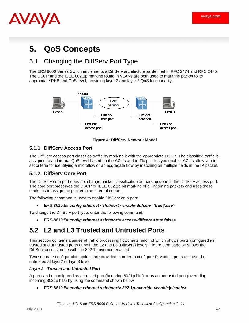
The ERS 8000 Series Switch implements a DiffServ architecture as defined in RFC 2474 and RFC 2475. The DSCP and the IEEE 802.1p marking found in VLANs are both used to mark the packet to its appropriate PHB and QoS level, providing layer 2 and layer 3 QoS functionality.
Figure 4: DiffServ Network Model
5.1.1 DiffServ Access Port
The DiffServ access port classifies traffic by marking it with the appropriate DSCP. The classified traffic is assigned to an internal QoS level based on the ACL‘s and traffic policies you enable. ACL‘s allow you to set criteria for identifying a microflow or an aggregate flow by matching on multiple fields in the IP packet.
5.1.2 DiffServ Core Port
The DiffServ core port does not change packet classification or marking done in the DiffServ access port. The core port preserves the DSCP or IEEE 802.1p bit marking of all incoming packets and uses these markings to assign the packet to an internal queue.
The following command is used to enable DiffServ on a port:
ERS-8610:5# config ethernet <slot/port> enable-diffserv <true|false>
To change the DiffServ port type, enter the following command:
ERS-8610:5# config ethernet <slot/port> access-diffserv <true|false>
5.2 L2 and L3 Trusted and Untrusted Ports
This section contains a series of traffic processing flowcharts, each of which shows ports configured as trusted and untrusted ports at both the L2 and L3 (DiffServ) levels. Figure 3 on page 36 shows the DiffServ access mode with the 802.1p override enabled.
Two separate configuration options are provided in order to configure R-Module ports as trusted or untrusted at layer2 or layer3 level.
Layer 2 - Trusted and Untrusted Port
A port can be configured as a trusted port (honoring 8021p bits) or as an untrusted port (overriding incoming 8021p bits) by using the command shown below.
ERS-8610:5# config ethernet <slot/port> 802.1p-override <enable|disable>
Filters and QoS for ERS 8600 R-Series Modules Technical Configuration Guide
43 July 2010
avaya.com
o 8021p-override enable ===== > Override incoming 8021p bits
o 8021p-override disable ===== > Honour and Service incoming 8021p bits
8021p-override is disabled in factory default config.
Layer 3 – Trusted and Untrusted Port
A port can be configured as a trusted (Core Port) and untrusted port (Access Port) at layer3. In order to configure a port as Core or Access port, DiffServ must be enabled.
ERS-8610:5# config ethernet <slot/port> enable-diffserv <false|true>
ERS-8610:5# config ethernet <slot/port> access-diffserv <false|true>
o access-diffserv = true (Access port) === > Override incoming DSCP bits
o access-diffserv = false(Core port) === > Honour and Service incoming
DSCP bits
DiffServ is disabled in factory default config.
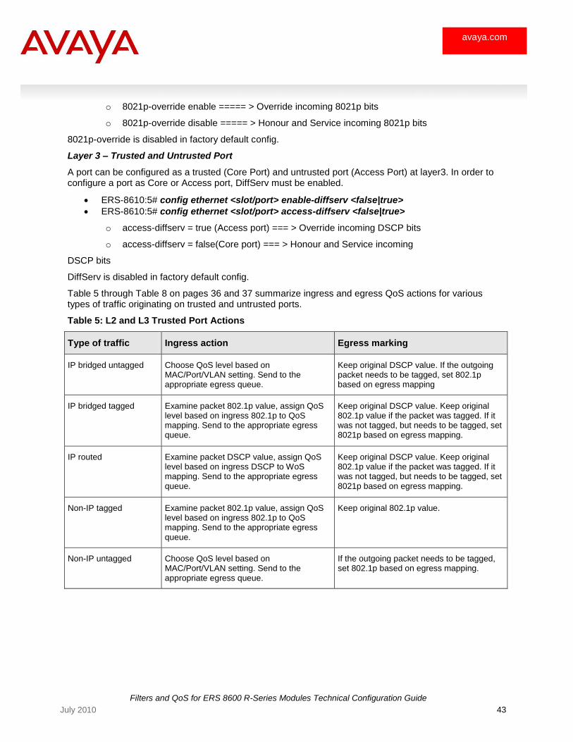
Table 5 through Table 8 on pages 36 and 37 summarize ingress and egress QoS actions for various types of traffic originating on trusted and untrusted ports.
Table 5: L2 and L3 Trusted Port Actions
Type of traffic Ingress action Egress marking
IP bridged untagged Choose QoS level based on MAC/Port/VLAN setting. Send to the appropriate egress queue.
Keep original DSCP value. If the outgoing packet needs to be tagged, set 802.1p based on egress mapping
IP bridged tagged Examine packet 802.1p value, assign QoS level based on ingress 802.1p to QoS mapping. Send to the appropriate egress queue.
Keep original DSCP value. Keep original 802.1p value if the packet was tagged. If it was not tagged, but needs to be tagged, set 8021p based on egress mapping.
IP routed Examine packet DSCP value, assign QoS level based on ingress DSCP to WoS mapping. Send to the appropriate egress queue.
Keep original DSCP value. Keep original 802.1p value if the packet was tagged. If it was not tagged, but needs to be tagged, set 8021p based on egress mapping.
Non-IP tagged Examine packet 802.1p value, assign QoS level based on ingress 802.1p to QoS mapping. Send to the appropriate egress queue.
Keep original 802.1p value.
Non-IP untagged Choose QoS level based on MAC/Port/VLAN setting. Send to the appropriate egress queue.
If the outgoing packet needs to be tagged, set 802.1p based on egress mapping.
Filters and QoS for ERS 8600 R-Series Modules Technical Configuration Guide
44 July 2010
avaya.com
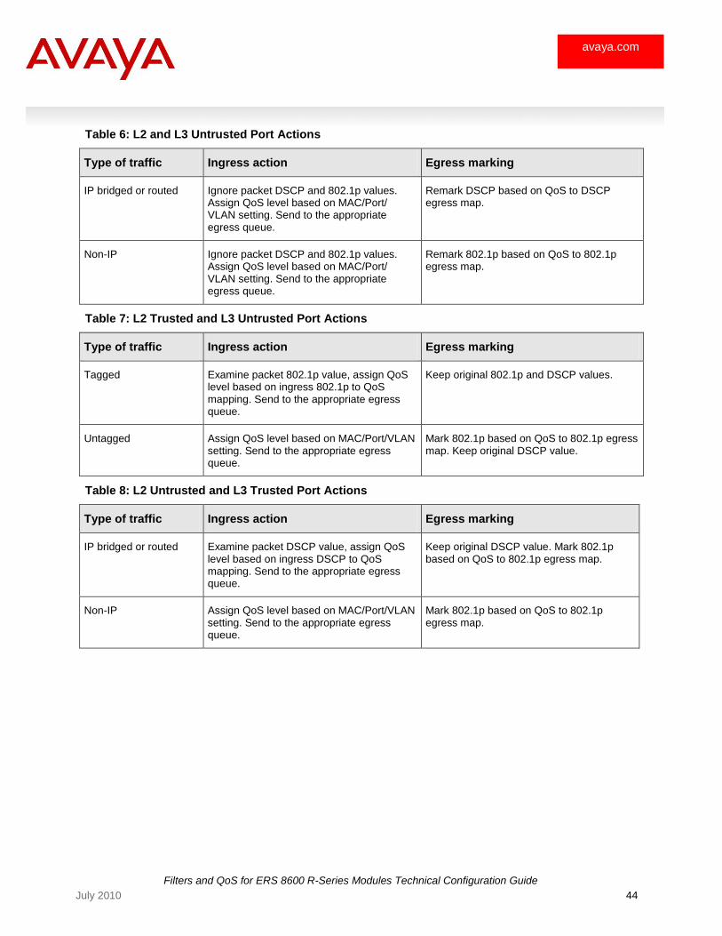
Table 6: L2 and L3 Untrusted Port Actions
Type of traffic Ingress action Egress marking
IP bridged or routed Ignore packet DSCP and 802.1p values. Assign QoS level based on MAC/Port/ VLAN setting. Send to the appropriate egress queue.
Remark DSCP based on QoS to DSCP egress map.
Non-IP Ignore packet DSCP and 802.1p values. Assign QoS level based on MAC/Port/ VLAN setting. Send to the appropriate egress queue.
Remark 802.1p based on QoS to 802.1p egress map.
Table 7: L2 Trusted and L3 Untrusted Port Actions
Type of traffic Ingress action Egress marking
Tagged Examine packet 802.1p value, assign QoS level based on ingress 802.1p to QoS mapping. Send to the appropriate egress queue.
Keep original 802.1p and DSCP values.
Untagged Assign QoS level based on MAC/Port/VLAN setting. Send to the appropriate egress queue.
Mark 802.1p based on QoS to 802.1p egress map. Keep original DSCP value.
Table 8: L2 Untrusted and L3 Trusted Port Actions
Type of traffic Ingress action Egress marking
IP bridged or routed Examine packet DSCP value, assign QoS level based on ingress DSCP to QoS mapping. Send to the appropriate egress queue.
Keep original DSCP value. Mark 802.1p based on QoS to 802.1p egress map.
Non-IP Assign QoS level based on MAC/Port/VLAN setting. Send to the appropriate egress queue.
Mark 802.1p based on QoS to 802.1p egress map.
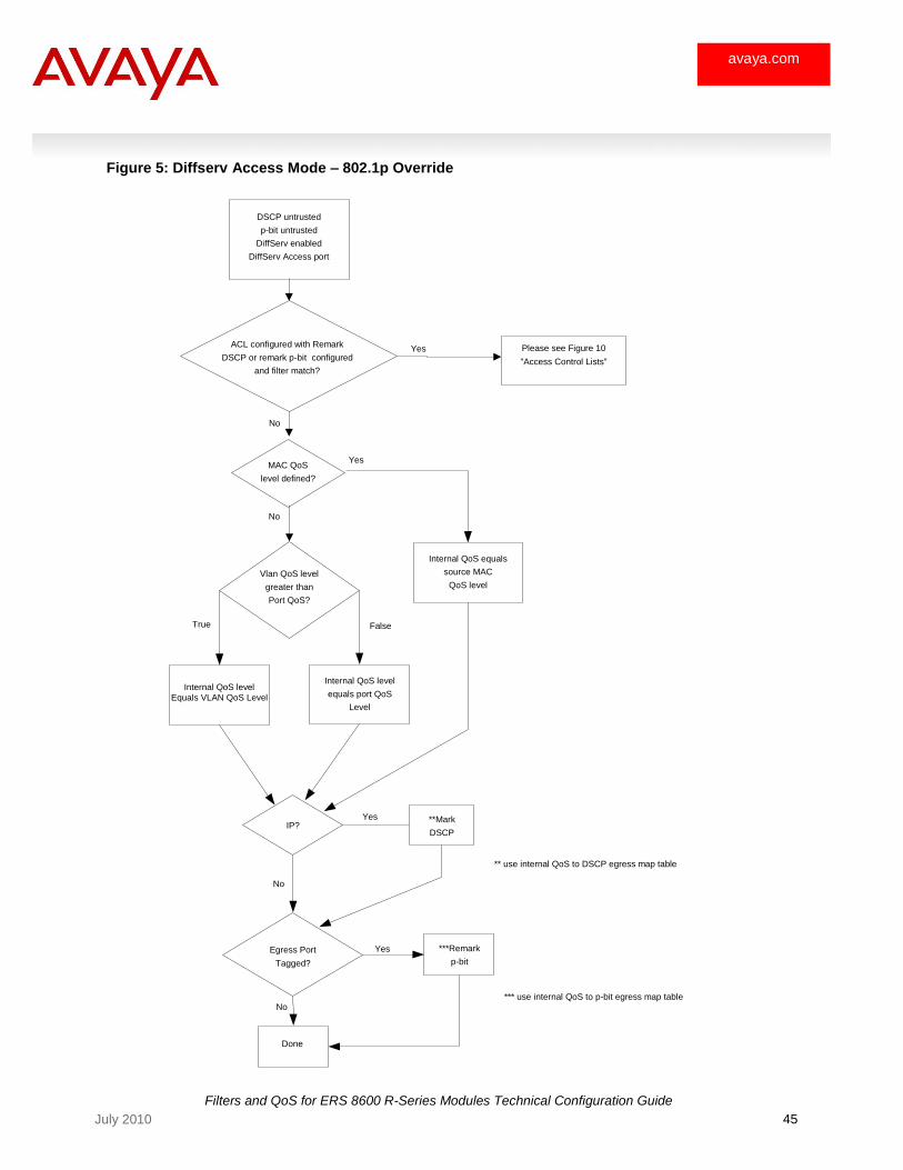
Filters and QoS for ERS 8600 R-Series Modules Technical Configuration Guide
45 July 2010
avaya.com
Figure 5: Diffserv Access Mode – 802.1p Override
DSCP untrusted
p-bit untrusted
DiffServ enabled
DiffServ Access port
ACL configured with Remark
DSCP or remark p-bit configured
and filter match?
MAC QoS
level defined?
Internal QoS level
equals port QoS
Level
Yes
No
Vlan QoS level
greater than
Port QoS?
Internal QoS level
Equals VLAN QoS Level
True False
Internal QoS equals
source MAC
QoS level
No
Yes
Egress Port Tagged?
Yes
No
**Mark
DSCP
IP?
No
Done
***Remark
p-bit
Yes
** use internal QoS to DSCP egress map table
*** use internal QoS to p-bit egress map table
Please see Figure 10
"Access Control Lists"

Filters and QoS for ERS 8600 R-Series Modules Technical Configuration Guide
46 July 2010
avaya.com
Figure 6: DiffServ Core Mode – 802.1p Override Enabled
p-bit untrusted
DSCP trusted
enable-diffserv = true
access-diffserv = false
802.1p-override enable
(DiffServ core port)
DSCP or remark p-bit configured
ACL configured with Remark
and filter match?
IP?
Yes
No
Mac QoS
level defined?
Internal QoS level
equals VLAN QoS
level
Yes No
No
Yes
Egress Port
Tagged?
No
**Mark
DSCP
Done
***Remark
p-bit
Yes
** use internal QoS to DSCP
egress map table
*** use internal QoS to p-bit egress map table
VLAN QoS level
greater than Port
QoS level?
Internal QoS level
equals port QoS
Level
True False
Use Ingressmap table to
assign QoS by honoring
incoming DSCP bits
(bridged and routed traffic
Internal QoS equals
source MAC
QoS level
Please see Figure 10
"Access Control Lists"
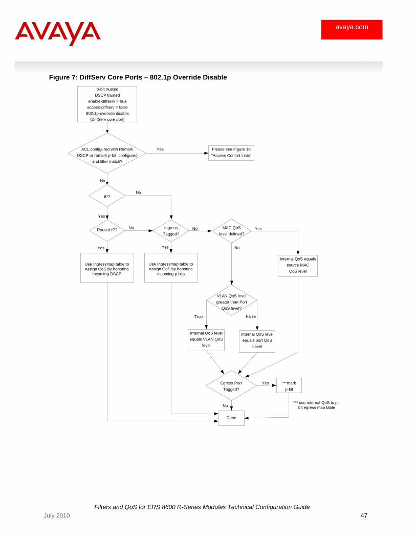
Filters and QoS for ERS 8600 R-Series Modules Technical Configuration Guide
47 July 2010
avaya.com
Figure 7: DiffServ Core Ports – 802.1p Override Disable
p-bit trusted
DSCP trusted
enable-diffserv = true
access-diffserv = false
802.1p-override disable
(DiffServ core port)
ACL configured with Remark
DSCP or remark p-bit configured
and filter match?
IP?
Yes
No
Internal QoS level
equals VLAN QoS
level
Yes
No
VLAN QoS level
greater than Port
QoS level?
Internal QoS level
equals port QoS
Level
True False
Routed IP? Ingress
Tagged?
No
Use Ingressmap table to
assign QoS by honoring
incoming DSCP
Use Ingressmap table to
assign QoS by honoring
incoming p-bits
No MAC QoS
level defined?
Yes
No
Egress Port
Tagged?
No
Done
***mark
p-bit
Yes
*** use internal QoS to p-
bit egress map table
Internal QoS equals
source MAC
QoS level
Please see Figure 10
"Access Control Lists"
Yes Yes

Filters and QoS for ERS 8600 R-Series Modules Technical Configuration Guide
48 July 2010
avaya.com
Figure 8: DiffServ Access Mode – 802.1p Override Disabled
p-bit trusted
DSCP untrusted
enable-diffserv = true
access-diffserv = true
802.1p-override disable
(DiffServ acess port
ACL configured with Remark
DSCP or remark p-bit configured
and filter match?
Ingress Packet
Tagged?
Yes
No
Internal QoS level
equals VLAN QoS
level
No
Yes
Egress Port
Tagged?
No
Done
***Remark
p-bit Yes
*** use internal QoS to p-bit egress map table
VLAN QoS level
greater than Port
QoS level?
Internal QoS level
equals port QoS
level
True False
Use Ingressmap table to
assign QoS by honoring
incoming p-bits
(bridged and routed traffic
Mac Qos level
defined? Yes
No
Internal QoS equals
source MAC
QoS level
Please see Figure 10
"Access Control Lists"
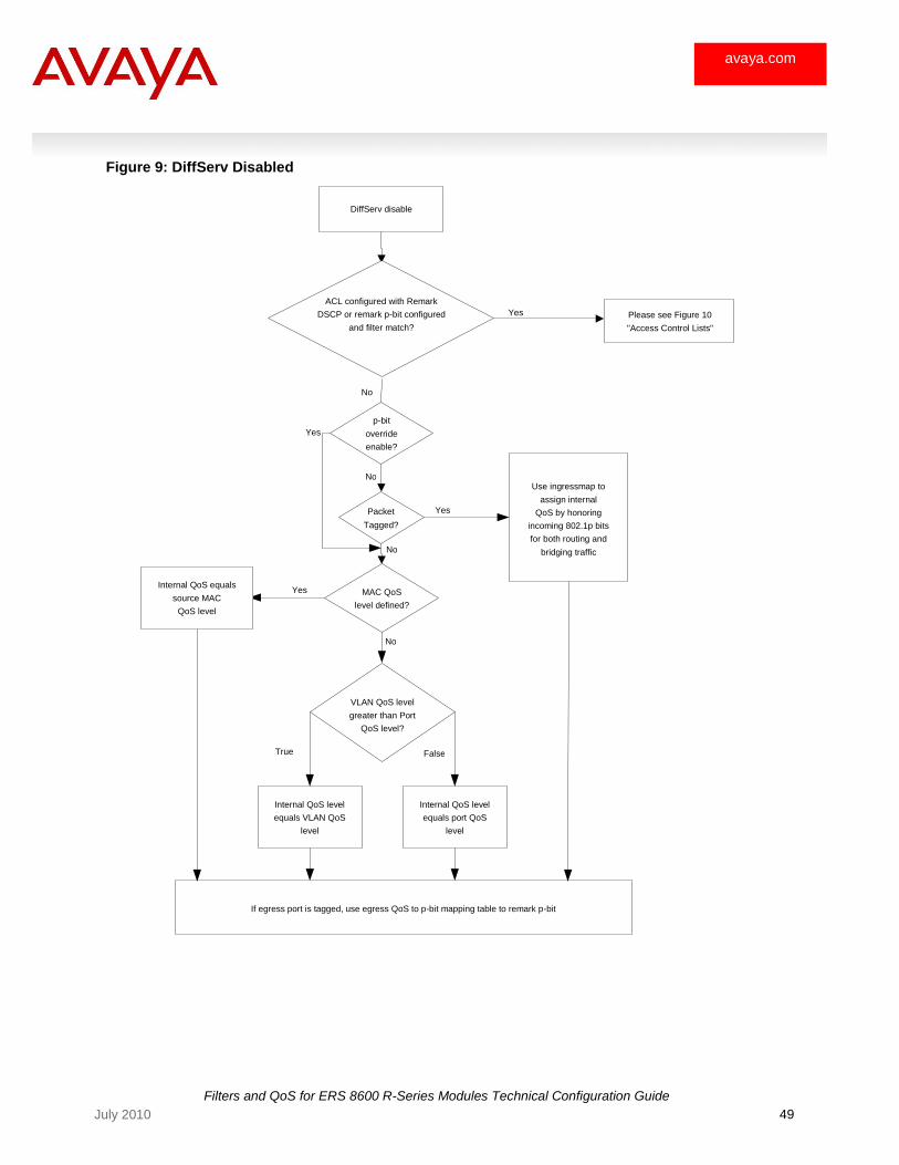
Filters and QoS for ERS 8600 R-Series Modules Technical Configuration Guide
49 July 2010
avaya.com
Figure 9: DiffServ Disabled
DiffServ disable
p-bit
override
enable?
Packet
Tagged?
Use ingressmap to
assign internal
QoS by honoring
incoming 802.1p bits
for both routing and
bridging traffic
No
Yes
ACL configured with Remark
DSCP or remark p-bit configured
and filter match?
Yes
No
No
Yes
MAC QoS
level defined?
No
Internal QoS level
equals VLAN QoS
level
VLAN QoS level
greater than Port
QoS level?
Internal QoS level
equals port QoS
level
True False
If egress port is tagged, use egress QoS to p-bit mapping table to remark p-bit
Internal QoS equals
source MAC
QoS level
Please see Figure 10
"Access Control Lists"
Yes
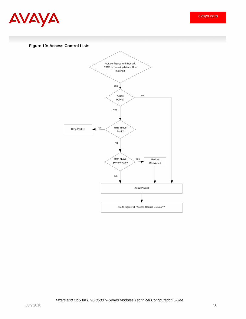
Filters and QoS for ERS 8600 R-Series Modules Technical Configuration Guide
50 July 2010
avaya.com
Figure 10: Access Control Lists
ACL configured with Remark
DSCP or remark p-bit and filter
matched
Action
Police?
Yes
Rate above
Peak?
Yes
No
Yes
No
Rate above
Service Rate?
Admit Packet
No
Yes
Drop Packet
Go to Figure 11 "Access Control Lists con't"
Packet
Re-colored
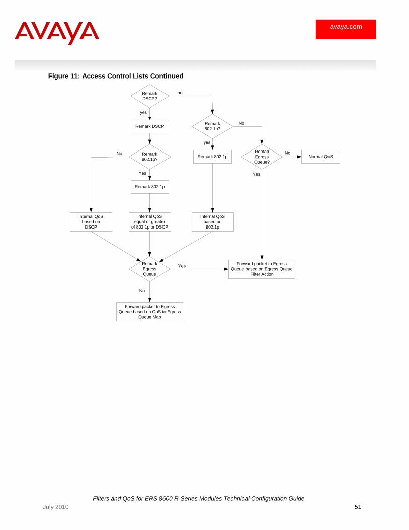
Filters and QoS for ERS 8600 R-Series Modules Technical Configuration Guide
51 July 2010
avaya.com
Figure 11: Access Control Lists Continued
Remark
DSCP?
No
yes
no
Remark
802.1p?
Internal QoS
equal or greater
of 802.1p or DSCP
Yes
Remark
802.1p?
yes
Remark DSCP
Remark 802.1p
Remark 802.1p
Internal QoS
based on
DSCP
Internal QoS
based on
802.1p
Remap
Egress
Queue?
Remark
Egress
Queue
Forward packet to Egress
Queue based on QoS to Egress
Queue Map
Normal QoS
No
Forward packet to Egress
Queue based on Egress Queue
Filter Action
Yes
Yes
No
No
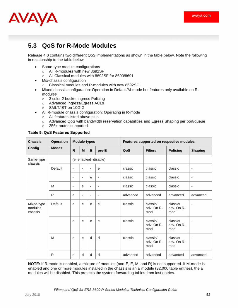
Filters and QoS for ERS 8600 R-Series Modules Technical Configuration Guide
52 July 2010
avaya.com
5.3 QoS for R-Mode Modules
Release 4.0 contains two different QoS implementations as shown in the table below. Note the following in relationship to the table below
Same-type module configurations o All R-modules with new 8692SF o All Classical modules with 8692SF for 8690/8691
Mix-chassis configuration o Classical modules and R-modules with new 8692SF
Mixed chassis configuration: Operation in Default/M-mode but features only available on R-modules o 3 color 2 bucket ingress Policing o Advanced Ingress/Egress ACLs o SMLT/IST on 10GIG
All R-module chassis configuration: Operating in R-mode o All features listed above plus o Advanced QoS with bandwidth reservation capabilities and Egress Shaping per port/queue o 256k routes supported
Table 9: QoS Features Supported
Chassis
Config
Operation
Modes
Module-types Features supported on respective modules
R M E pre-E QoS Filters Policing Shaping
Same-type chassis
(e=enable/d=disable)
Default - - - e classic classic classic -
- - e - classic classic classic -
M - e - - classic classic classic -
R e - - - advanced advanced advanced advanced
Mixed-type modules chassis
Default e e e e classic classic/ adv. On R-mod
classic/ adv. On R-mod
-
e e e e classic classic/ adv. On R-mod
classic/ adv. On R-mod
-
M e e d d classic classic/ adv. On R-mod
classic/ adv. On R-mod
-
R e d d d advanced advanced advanced advanced
NOTE: If R-mode is enabled, a mixture of modules (non-E, E, M, and R) is not supported. If M-mode is enabled and one or more modules installed in the chassis is an E module (32,000 table entries), the E modules will be disabled. This protects the system forwarding tables from lost entries.
Filters and QoS for ERS 8600 R-Series Modules Technical Configuration Guide
53 July 2010
avaya.com
5.3.1 Configuring R-mode
To configure the switch for R-mode, use the following commands. Note that after the switch has been set for R-mode, the configuration should be saved and the switch must be rebooted.
ERS-8610:5# config sys set flags ?
Sub-Context:
Current Context:
r-mode <true|false>
m-mode <true|false>
enhanced-operational-mode <true|false>
vlan-optimization-mode <true|false>
info
ERS-8610:5# config sys set flags r-mode true
ERS-8610:5# save config
ERS-8610:5# boot -y
5.4 Changing the Default Port or VLAN QoS Levels
The default port or VLAN QoS levels can be changed to assign a default QoS level for all traffic providing the packet is not matched by an ACL to remark the packet. By default, the port and VLAN QoS level is set to 1 (one).
To change to port QoS level, enter the command below:
ERS-8610:5# config ethernet <slot/port> qos-level ?
set Internal Qos Level for a port
Required parameters:
<0...7> = operation {0..7}
Command syntax:
qos-level <0...7>
To change the VLAN QoS level, enter the command below:
ERS-8610:5# config vlan <vlan #> qos-level ?
set Internal Qos Level for a vlan
Required parameters:
<0...7> = operation {0..7}
Command syntax:
qos-level <0...7>

Filters and QoS for ERS 8600 R-Series Modules Technical Configuration Guide
54 July 2010
avaya.com
5.5 Adding a MAC QoS Level
A QoS level can also be applied to a source MAC address again providing the packet is not matched by an ACL to remark the packet. The MAC QoS level can be modified to a learned MAC address to add to a static MAC enter.
To change the source MAC QoS level to a dynamic learned address, enter the command below:
ERS-8610:5# config vlan <vlan #> fdb-entry qos-level ?
set fdb Qos Level
Required parameters:
<mac> = mac address {0x00:0x00:0x00:0x00:0x00:0x00}
status <value> = fdb status {other|invalid|learned|self|mgmt}
<0...7> = set qos level 0..7 {0..7}
Command syntax:
qos-level <mac> status <value> <0...7>
To change the source MAC QoS level to a static address, enter the command below:
ERS-8610:5# config vlan <vlan #> fdb-static ?
Sub-Context:
Current Context:
add <mac> port <value> qos <value>
info
remove <mac>
For example, to change the source MAC QoS level to 2 for the MAC address 00:00:00:00:01:0a on VLAN 2 via port 7/26, enter the command below:
ERS-8610:5# config vlan 2 fdb-static add 00:00:00:00:01:0a port 7/26 qos 2
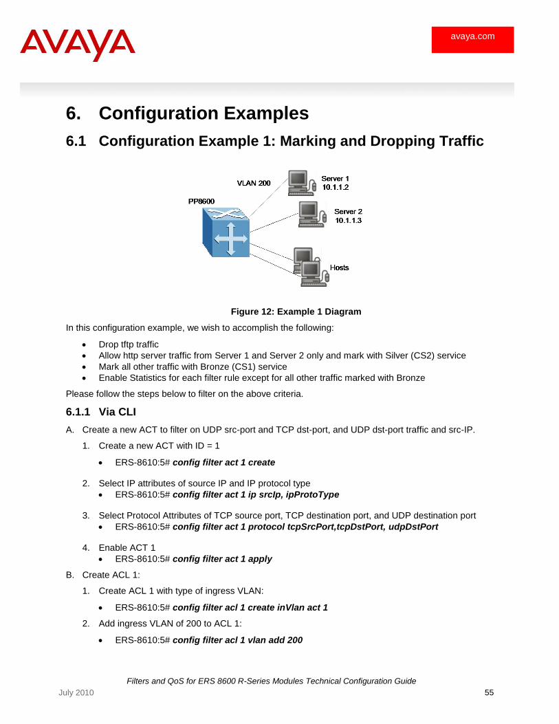
Filters and QoS for ERS 8600 R-Series Modules Technical Configuration Guide
55 July 2010
avaya.com
6. Configuration Examples
6.1 Configuration Example 1: Marking and Dropping Traffic
Figure 12: Example 1 Diagram
In this configuration example, we wish to accomplish the following:
Drop tftp traffic
Allow http server traffic from Server 1 and Server 2 only and mark with Silver (CS2) service
Mark all other traffic with Bronze (CS1) service
Enable Statistics for each filter rule except for all other traffic marked with Bronze
Please follow the steps below to filter on the above criteria.
6.1.1 Via CLI
A. Create a new ACT to filter on UDP src-port and TCP dst-port, and UDP dst-port traffic and src-IP.
1. Create a new ACT with ID = 1
ERS-8610:5# config filter act 1 create
2. Select IP attributes of source IP and IP protocol type
ERS-8610:5# config filter act 1 ip srcIp, ipProtoType
3. Select Protocol Attributes of TCP source port, TCP destination port, and UDP destination port
ERS-8610:5# config filter act 1 protocol tcpSrcPort,tcpDstPort, udpDstPort
4. Enable ACT 1
ERS-8610:5# config filter act 1 apply
B. Create ACL 1:
1. Create ACL 1 with type of ingress VLAN:
ERS-8610:5# config filter acl 1 create inVlan act 1
2. Add ingress VLAN of 200 to ACL 1:
ERS-8610:5# config filter acl 1 vlan add 200
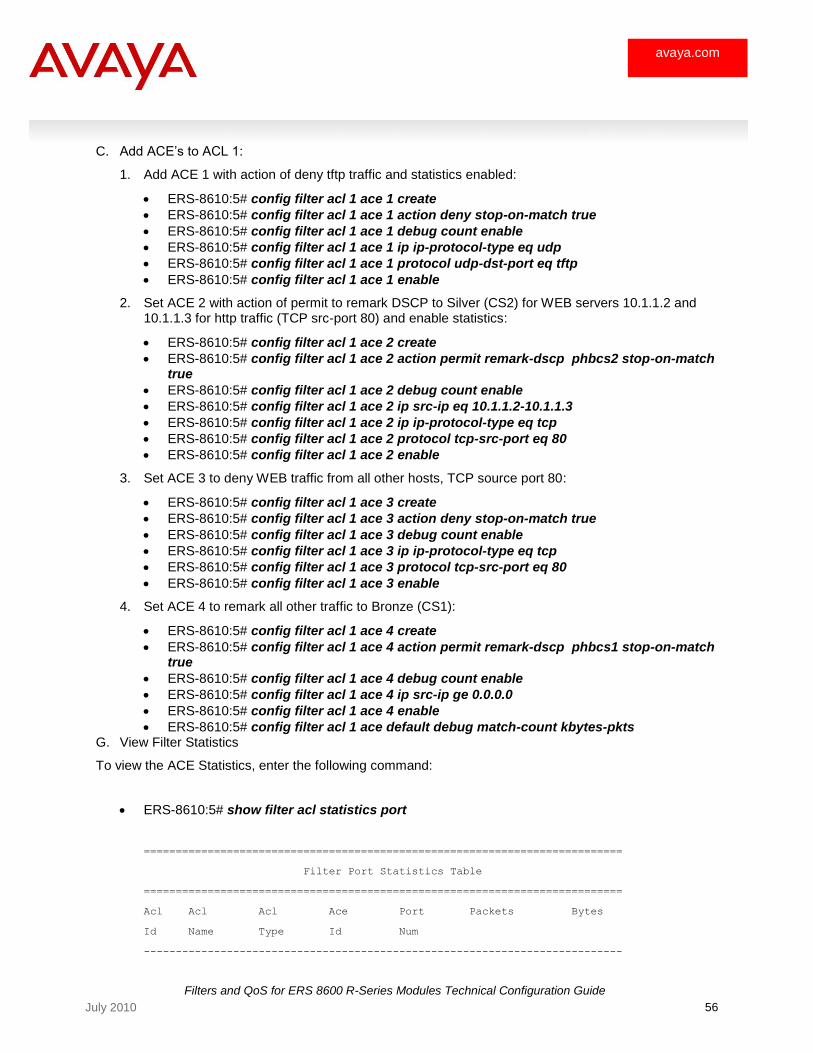
Filters and QoS for ERS 8600 R-Series Modules Technical Configuration Guide
56 July 2010
avaya.com
C. Add ACE‘s to ACL 1:
1. Add ACE 1 with action of deny tftp traffic and statistics enabled:
ERS-8610:5# config filter acl 1 ace 1 create
ERS-8610:5# config filter acl 1 ace 1 action deny stop-on-match true
ERS-8610:5# config filter acl 1 ace 1 debug count enable
ERS-8610:5# config filter acl 1 ace 1 ip ip-protocol-type eq udp
ERS-8610:5# config filter acl 1 ace 1 protocol udp-dst-port eq tftp
ERS-8610:5# config filter acl 1 ace 1 enable
2. Set ACE 2 with action of permit to remark DSCP to Silver (CS2) for WEB servers 10.1.1.2 and 10.1.1.3 for http traffic (TCP src-port 80) and enable statistics:
ERS-8610:5# config filter acl 1 ace 2 create
ERS-8610:5# config filter acl 1 ace 2 action permit remark-dscp phbcs2 stop-on-match true
ERS-8610:5# config filter acl 1 ace 2 debug count enable
ERS-8610:5# config filter acl 1 ace 2 ip src-ip eq 10.1.1.2-10.1.1.3
ERS-8610:5# config filter acl 1 ace 2 ip ip-protocol-type eq tcp
ERS-8610:5# config filter acl 1 ace 2 protocol tcp-src-port eq 80
ERS-8610:5# config filter acl 1 ace 2 enable
3. Set ACE 3 to deny WEB traffic from all other hosts, TCP source port 80:
ERS-8610:5# config filter acl 1 ace 3 create
ERS-8610:5# config filter acl 1 ace 3 action deny stop-on-match true
ERS-8610:5# config filter acl 1 ace 3 debug count enable
ERS-8610:5# config filter acl 1 ace 3 ip ip-protocol-type eq tcp
ERS-8610:5# config filter acl 1 ace 3 protocol tcp-src-port eq 80
ERS-8610:5# config filter acl 1 ace 3 enable
4. Set ACE 4 to remark all other traffic to Bronze (CS1):
ERS-8610:5# config filter acl 1 ace 4 create
ERS-8610:5# config filter acl 1 ace 4 action permit remark-dscp phbcs1 stop-on-match true
ERS-8610:5# config filter acl 1 ace 4 debug count enable
ERS-8610:5# config filter acl 1 ace 4 ip src-ip ge 0.0.0.0
ERS-8610:5# config filter acl 1 ace 4 enable
ERS-8610:5# config filter acl 1 ace default debug match-count kbytes-pkts G. View Filter Statistics
To view the ACE Statistics, enter the following command:
ERS-8610:5# show filter acl statistics port
===========================================================================
Filter Port Statistics Table
===========================================================================
Acl Acl Acl Ace Port Packets Bytes
Id Name Type Id Num
---------------------------------------------------------------------------
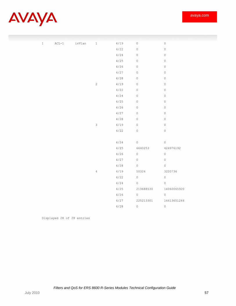
Filters and QoS for ERS 8600 R-Series Modules Technical Configuration Guide
57 July 2010
avaya.com
1 ACL-1 inVlan 1 4/19 0 0
4/22 0 0
4/24 0 0
4/25 0 0
4/26 0 0
4/27 0 0
4/28 0 0
2 4/19 0 0
4/22 0 0
4/24 0 0
4/25 0 0
4/26 0 0
4/27 0 0
4/28 0 0
3 4/19 0 0
4/22 0 0
4/24 0 0
4/25 6640253 424976192
4/26 0 0
4/27 0 0
4/28 0 0
4 4/19 50324 3220736
4/22 0 0
4/24 0 0
4/25 219688530 14060065920
4/26 0 0
4/27 225213301 14413651264
4/28 0 0
Displayed 28 of 28 entries
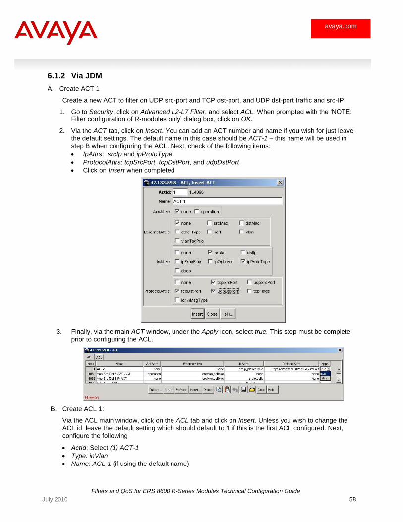
Filters and QoS for ERS 8600 R-Series Modules Technical Configuration Guide
58 July 2010
avaya.com
6.1.2 Via JDM
A. Create ACT 1
Create a new ACT to filter on UDP src-port and TCP dst-port, and UDP dst-port traffic and src-IP.
1. Go to Security, click on Advanced L2-L7 Filter, and select ACL. When prompted with the ‗NOTE: Filter configuration of R-modules only‘ dialog box, click on OK.
2. Via the ACT tab, click on Insert. You can add an ACT number and name if you wish for just leave the default settings. The default name in this case should be ACT-1 – this name will be used in step B when configuring the ACL. Next, check of the following items:
IpAttrs: srcIp and ipProtoType
ProtocolAttrs: tcpSrcPort, tcpDstPort, and udpDstPort
Click on Insert when completed
3. Finally, via the main ACT window, under the Apply icon, select true. This step must be complete prior to configuring the ACL.
B. Create ACL 1:
Via the ACL main window, click on the ACL tab and click on Insert. Unless you wish to change the ACL id, leave the default setting which should default to 1 if this is the first ACL configured. Next, configure the following
ActId: Select (1) ACT-1
Type: inVlan
Name: ACL-1 (if using the default name)
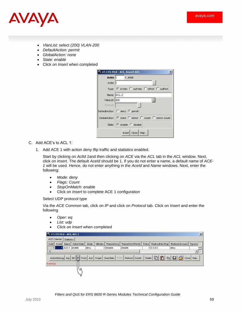
Filters and QoS for ERS 8600 R-Series Modules Technical Configuration Guide
59 July 2010
avaya.com
VlanList: select (200) VLAN-200
DefaultAction: permit
GlobalAction: none
State: enable
Click on Insert when completed
C. Add ACE‘s to ACL 1:
1. Add ACE 1 with action deny tftp traffic and statistics enabled.
Start by clicking on AclId 1and then clicking on ACE via the ACL tab in the ACL window. Next, click on Insert. The default AceId should be 1. If you do not enter a name, a default name of ACE-1 will be used. Hence, do not enter anything in the AceId and Name windows. Next, enter the following:
Mode: deny
Flags: Count
StopOnMatch: enable
Click on Insert to complete ACE 1 configuration
Select UDP protocol type
Via the ACE Common tab, click on IP and click on Protocol tab. Click on Insert and enter the following
Oper: eq
List: udp
Click on Insert when completed
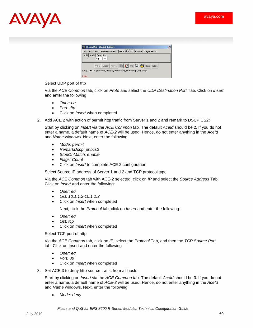
Filters and QoS for ERS 8600 R-Series Modules Technical Configuration Guide
60 July 2010
avaya.com
Select UDP port of tftp
Via the ACE Common tab, click on Proto and select the UDP Destination Port Tab. Click on Insert and enter the following
Oper: eq
Port: tftp
Click on Insert when completed
2. Add ACE 2 with action of permit http traffic from Server 1 and 2 and remark to DSCP CS2:
Start by clicking on Insert via the ACE Common tab. The default AceId should be 2. If you do not enter a name, a default name of ACE-2 will be used. Hence, do not enter anything in the AceId and Name windows. Next, enter the following:
Mode: permit
RemarkDscp: phbcs2
StopOnMatch: enable
Flags: Count
Click on Insert to complete ACE 2 configuration
Select Source IP address of Server 1 and 2 and TCP protocol type
Via the ACE Common tab with ACE-2 selected, click on IP and select the Source Address Tab. Click on Insert and enter the following:
Oper: eq
List: 10.1.1.2-10.1.1.3
Click on Insert when completed
Next, click the Protocol tab, click on Insert and enter the following:
Oper: eq
List: tcp
Click on Insert when completed
Select TCP port of http
Via the ACE Common tab, click on IP, select the Protocol Tab, and then the TCP Source Port tab. Click on Insert and enter the following
Oper: eq
Port: 80
Click on Insert when completed
3. Set ACE 3 to deny http source traffic from all hosts
Start by clicking on Insert via the ACE Common tab. The default AceId should be 3. If you do not enter a name, a default name of ACE-3 will be used. Hence, do not enter anything in the AceId and Name windows. Next, enter the following:
Mode: deny
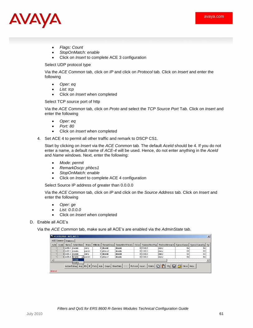
Filters and QoS for ERS 8600 R-Series Modules Technical Configuration Guide
61 July 2010
avaya.com
Flags: Count
StopOnMatch: enable
Click on Insert to complete ACE 3 configuration
Select UDP protocol type
Via the ACE Common tab, click on IP and click on Protocol tab. Click on Insert and enter the following
Oper: eq
List: tcp
Click on Insert when completed
Select TCP source port of http
Via the ACE Common tab, click on Proto and select the TCP Source Port Tab. Click on Insert and enter the following
Oper: eq
Port: 80
Click on Insert when completed
4. Set ACE 4 to permit all other traffic and remark to DSCP CS1.
Start by clicking on Insert via the ACE Common tab. The default AceId should be 4. If you do not enter a name, a default name of ACE-4 will be used. Hence, do not enter anything in the AceId and Name windows. Next, enter the following:
Mode: permit
RemarkDscp: phbcs1
StopOnMatch: enable
Click on Insert to complete ACE 4 configuration
Select Source IP address of greater than 0.0.0.0
Via the ACE Common tab, click on IP and click on the Source Address tab. Click on Insert and enter the following
Oper: ge
List: 0.0.0.0
Click on Insert when completed
D. Enable all ACE‘s
Via the ACE Common tab, make sure all ACE‘s are enabled via the AdminState tab.
Filters and QoS for ERS 8600 R-Series Modules Technical Configuration Guide
62 July 2010
avaya.com
6.1.3 Changing the Default Egress Queue
In the configuration above, we simply configured an ACL with two ACEs to remark the DSCP value upon a filter match. An ACE can also be configured to either select a ADSSC color or Egress Queue number to override the default ingress/egress queue mapping.
The following command is used to change the default ADSSC color:
ERS-8610:5# config filter acl <value> ace <value> action permit remark-dscp <value> egress-queue-nnsc <critical|custom|premium| platinum |gold|silver|bronze|standard|disable>
ERS-8610:5# config filter acl <value> ace <value> action permit remark-dot1p <value> egress-queue-nnsc <critical|custom|premium| platinum|gold|silver|bronze|standard|disable>
The following command is used to change the default ADSSC queue number:
ERS-8610:5# config filter acl <value> ace <value> action permit remark-dscp <value> egress-queue <0..64>
or
ERS-8610:5# config filter acl <value> ace <value> action permit remark-dscp <value> egress-queue <0..64>,<0..64>
or
ERS-8610:5# config filter acl <value> ace <value> action permit remark-dscp <value> egress-queue <0..64>,<0..64>,<0..64>
ERS-8610:5# config filter acl <value> ace <value> action permit remark-dot1p <value> egress-queue <0..64>
or
ERS-8610:5# config filter acl <value> ace <value> action permit remark- dot1p <value> egress-queue <0..64>,<0..64>
or
ERS-8610:5# config filter acl <value> ace <value> action permit remark- dot1p <value> egress-queue <0..64>,<0..64>,<0..64>
NOTE: The egress queue number can be a single value, 2 values or 3 values. The three values are for Egress Queue ID for 10/100 I/O module, Queue ID for 1GigE I/O module, and Queue ID for 10GigE I/O module. If only one value is specified, the same value is applied to all three I/O module types. If two values are specified, the first value is applied to 10/100 I/O modules, and the second value is applied to 1 GigE and 10 GigE I/O modules. If three values are specified, the three values are applied to 10/100, 1 GigE, and 10 GigE I/O modules respectively.
NOTE: If you are not using one of the default queue sets, i.e. queue set 1 or 2, you must use ACL‘s to remark and select the appropriate queue if the new queue set does not use the same queue ID‘s or uses additional queues than either of the two default queue sets. However, if the new queue set uses the same queue ID with the same number of queues as that of either of the two default queue set, then ACL‘s are not required to map traffic to the appropriate queue.
Filters and QoS for ERS 8600 R-Series Modules Technical Configuration Guide
63 July 2010
avaya.com
View Commands:
To view the default QoS Ingress mapping, use the following command:
ERS-8610:5# show qos ingressmap ?
Sub-Context:
Current Context:
1p [<ieee1p>]
ds [<dscp>]
To view the default QoS Egress mapping, use the following command:
ERS-8610:5# show qos egressmap ?
Sub-Context:
Current Context:
1p [<level>]
ds [<level>]
To view the default internal QoS to Egress Queue mapping, use the following command:
ERS-8610:5# show qos config eqmap <slot number>
To view the QoS level and shaper table, enter the following command:
ERS-8610:5# show qos config egress-queue-set egress-queue-set <1..386> queues
Where queue 1 is the default queue set for the 10/100/1000 I/O module and queue 2 is the default queue set for the GigE and 10 GigE I/O modules. For example, to view the GigE default queue set, enter the following command:
ERS-8610:5# show qos config egress-queue-set egress-queue-set 2 queues
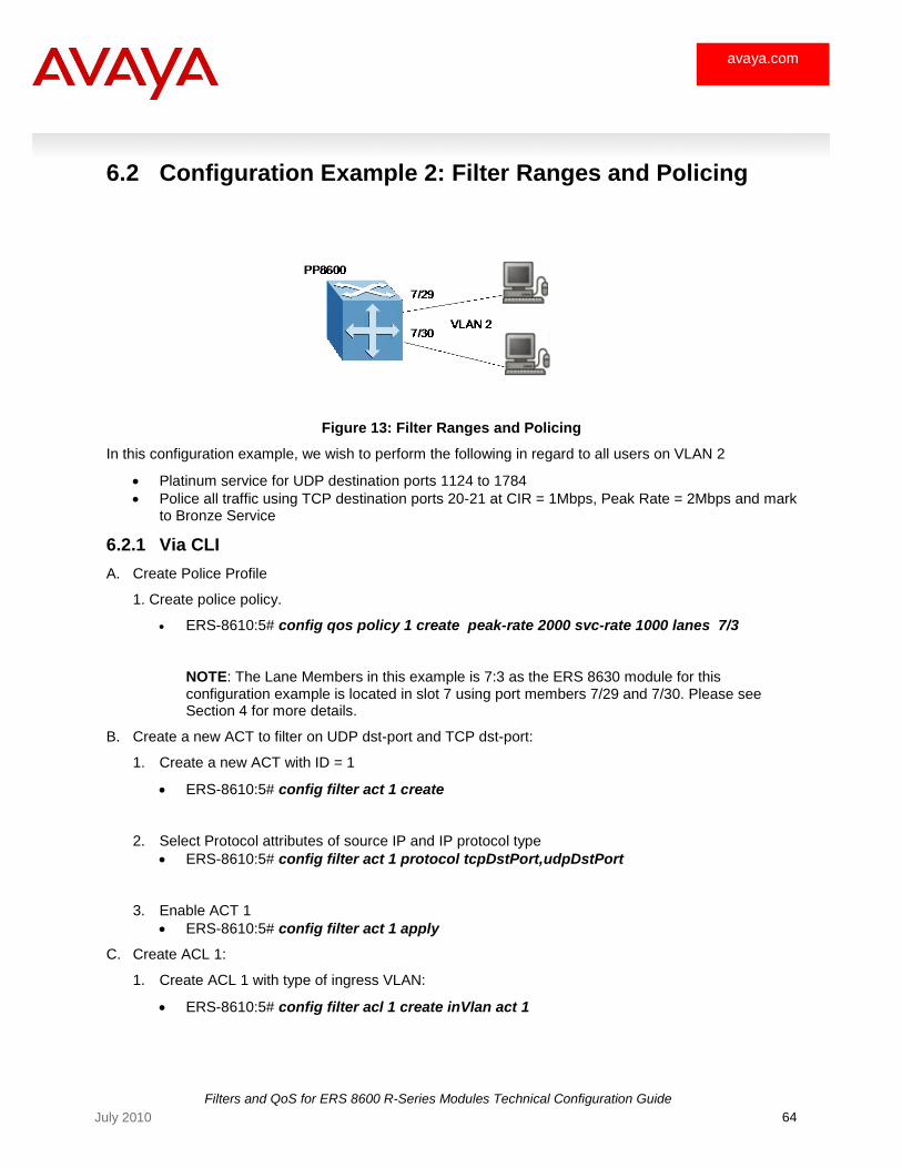
Filters and QoS for ERS 8600 R-Series Modules Technical Configuration Guide
64 July 2010
avaya.com
6.2 Configuration Example 2: Filter Ranges and Policing
Figure 13: Filter Ranges and Policing
In this configuration example, we wish to perform the following in regard to all users on VLAN 2
Platinum service for UDP destination ports 1124 to 1784
Police all traffic using TCP destination ports 20-21 at CIR = 1Mbps, Peak Rate = 2Mbps and mark to Bronze Service
6.2.1 Via CLI
A. Create Police Profile
1. Create police policy.
ERS-8610:5# config qos policy 1 create peak-rate 2000 svc-rate 1000 lanes 7/3
NOTE: The Lane Members in this example is 7:3 as the ERS 8630 module for this configuration example is located in slot 7 using port members 7/29 and 7/30. Please see Section 4 for more details.
B. Create a new ACT to filter on UDP dst-port and TCP dst-port:
1. Create a new ACT with ID = 1
ERS-8610:5# config filter act 1 create
2. Select Protocol attributes of source IP and IP protocol type
ERS-8610:5# config filter act 1 protocol tcpDstPort,udpDstPort
3. Enable ACT 1
ERS-8610:5# config filter act 1 apply
C. Create ACL 1:
1. Create ACL 1 with type of ingress VLAN:
ERS-8610:5# config filter acl 1 create inVlan act 1
Filters and QoS for ERS 8600 R-Series Modules Technical Configuration Guide
65 July 2010
avaya.com
2. Add ingress VLAN of 2 to ACL 1:
ERS-8610:5# config filter acl 1 vlan add 2
D. Create ACE‘s to ACL 1:
1. Add ACE 1 with action of permit to remark DSCP to AF41 for UDP port range 1124-1784 and statistics enabled:
ERS-8610:5# config filter acl 1 ace 1 create name UDP-Range
ERS-8610:5# config filter acl 1 ace 1 action permit remark-dscp phbaf41
ERS-8610:5# config filter acl 1 ace 1 debug count enable
ERS-8610:5# config filter acl 1 ace 1 protocol udp-dst-port eq 1124-1784
ERS-8610:5# config filter acl 1 ace 1 enable
2. Set ACE 2 with action of permit to remark DSCP to Bronze for TCP ports 20-21 and enable statistics:
ERS-8610:5# config filter acl 1 ace 2 create name Police_1
ERS-8610:5# config filter acl 1 ace 2 action permit remark-dscp phbaf11 police 1
ERS-8610:5# config filter acl 1 ace 2 debug count enable
ERS-8610:5# config filter acl 1 ace 2 protocol tcp-dst-port eq 20-21
ERS-8610:5# config filter acl 1 ace 2 enable
6.2.2 Via JDM
A. Create Police Policy
Create a new police policy with a sustained rate of 1M and a peak rate of 2M:
1. Go to QoS, select Policy and then click on Insert. Unless you wish to change the GrId and Policy Name, leave the default setting of 1 and POLICY-1 respectively.
2. Next enter the following:
PeakRate: 2000
SvcRate: 1000
LaneMembers: 7:3 (Port 7/21-30)
Click on Insert when completed
NOTE: The Lane Members in this example is 7:3 as the ERS 8630 module for this configuration example is located in slot 7 using port members 7/29 and 7/30. Please see Section 4 for more details.
B. Create ACT 1
Create a new ACT to filter on UDP src-port and TCP src-port.
1. Go to Security, click on Advanced L2-L7 Filter, and select ACL. When prompted with the ‗NOTE: Filter configuration of R-modules only‘ dialog box, click on OK.
2. Via the ACT tab, click on Insert. You can add an ACT number and name if you wish for just leave the default settings. The default name in this case should be ACT-1 – this name will be used in step B when configuring the ACL. Next, check of the following items:
ProtocolAttrs: tcpSrcPort and udpSrcPort
Click on Insert when completed

Filters and QoS for ERS 8600 R-Series Modules Technical Configuration Guide
66 July 2010
avaya.com
3. Finally, via the main ACT window, under the Apply icon, select true. This step must be complete prior to configuring the ACL.
C. Create ACL 1:
Via the ACL main window, click on the ACL tab and click on Insert. Unless you wish to change the ACL id, leave the default setting which should default to 1 if this is the first ACL configured. Next, configure the following:
ActId: Select (1) ACT-1
Type: inVlan
Name: ACL-1 (if using the default name)
VlanList: select (2) VLAN-2
DefaultAction: permit
GlobalAction: none
State: enable
Click on Insert when completed
D. Add ACE‘s to ACL 1:
1. Add ACE 1 with action of permit, remark DSCP to AF41 and statistics enabled for UDP port range 1124 to 1754.
Start by clicking on AclId 1and then clicking on ACE via the ACL tab in the ACL window. Next, click on Insert. The default AceId should be 1. If you do not enter a name, a default name of ACE-1 will be used. Hence, do not enter anything in the AceId and Name windows. Next, enter the following:
Mode: permit
RemarkDscp: phbaf41
Flags: Count
Click on Insert to complete ACE 1 configuration
Select UDP protocol type and range
Via the ACE Common tab, highlight AceId 1, click on Proto and click on UDPDestination Port tab. Click on Insert and enter the following:
Oper: eq
Port: 1124-1754
Click on Insert when completed
2. Add ACE 2 with action of permit, remark DSCP to AF11 and statistics enabled for TCP port range 20 to 20.
Start by clicking on Insert via the ACE Common tab. The default AceId should be 2. If you do not enter a name, a default name of ACE-2 will be used. Hence, do not enter anything in the AceId and Name windows. Next, enter the following:
Mode: permit
RemarkDscp: phbaf11
Police: 1
Flags: Count
Click on Insert to complete ACE 2 configuration
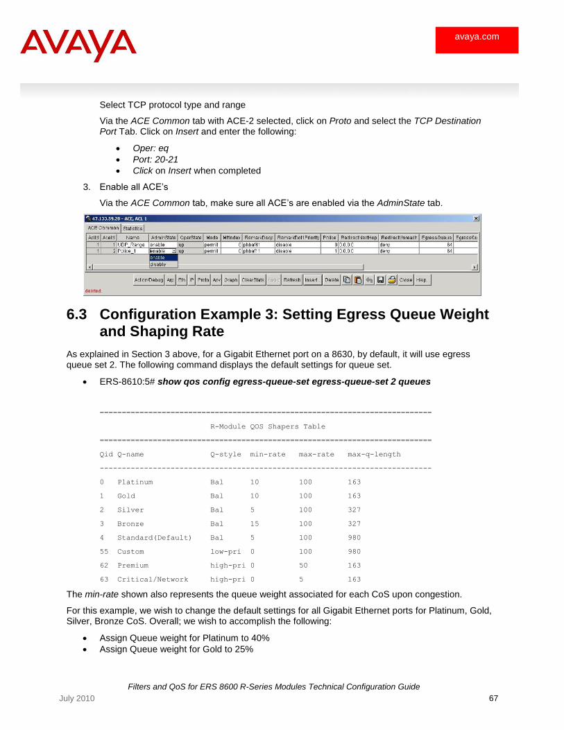
Filters and QoS for ERS 8600 R-Series Modules Technical Configuration Guide
67 July 2010
avaya.com
Select TCP protocol type and range
Via the ACE Common tab with ACE-2 selected, click on Proto and select the TCP Destination Port Tab. Click on Insert and enter the following:
Oper: eq
Port: 20-21
Click on Insert when completed
3. Enable all ACE‘s
Via the ACE Common tab, make sure all ACE‘s are enabled via the AdminState tab.
6.3 Configuration Example 3: Setting Egress Queue Weight and Shaping Rate
As explained in Section 3 above, for a Gigabit Ethernet port on a 8630, by default, it will use egress queue set 2. The following command displays the default settings for queue set.
ERS-8610:5# show qos config egress-queue-set egress-queue-set 2 queues
===========================================================================
R-Module QOS Shapers Table
===========================================================================
Qid Q-name Q-style min-rate max-rate max-q-length
---------------------------------------------------------------------------
0 Platinum Bal 10 100 163
1 Gold Bal 10 100 163
2 Silver Bal 5 100 327
3 Bronze Bal 15 100 327
4 Standard(Default) Bal 5 100 980
55 Custom low-pri 0 100 980
62 Premium high-pri 0 50 163
63 Critical/Network high-pri 0 5 163
The min-rate shown also represents the queue weight associated for each CoS upon congestion.
For this example, we wish to change the default settings for all Gigabit Ethernet ports for Platinum, Gold, Silver, Bronze CoS. Overall; we wish to accomplish the following:
Assign Queue weight for Platinum to 40%
Assign Queue weight for Gold to 25%
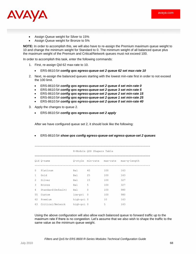
Filters and QoS for ERS 8600 R-Series Modules Technical Configuration Guide
68 July 2010
avaya.com
Assign Queue weight for Silver to 15%
Assign Queue weight for Bronze to 5%
NOTE: In order to accomplish this, we will also have to re-assign the Premium maximum queue weight to 10 and change the minimum weight for Standard to 0. The minimum weight of all balanced queue plus the maximum weight of the Premium and Critical/Network queues must not exceed 100.
In order to accomplish this task, enter the following commands:
1. First, re-assign Qid 62 max-rate to 10.
ERS-8610:5# config qos egress-queue-set 2 queue 62 set max-rate 10
2. Next, re-assign the balanced queues starting with the lowest min-rate first in order to not exceed the 100 limit.
ERS-8610:5# config qos egress-queue-set 2 queue 4 set min-rate 0
ERS-8610:5# config qos egress-queue-set 2 queue 3 set min-rate 5
ERS-8610:5# config qos egress-queue-set 2 queue 2 set min-rate 15
ERS-8610:5# config qos egress-queue-set 2 queue 1 set min-rate 25
ERS-8610:5# config qos egress-queue-set 2 queue 0 set min-rate 40
3. Apply the changes to queue 2.
ERS-8610:5# config qos egress-queue-set 2 apply
After we have configured queue set 2, it should look like the following:
ERS-8610:5# show qos config egress-queue-set egress-queue-set 2 queues
===========================================================================
R-Module QOS Shapers Table
===========================================================================
Qid Q-name Q-style min-rate max-rate max-q-length
---------------------------------------------------------------------------
0 Platinum Bal 40 100 163
1 Gold Bal 25 100 163
2 Silver Bal 15 100 327
3 Bronze Bal 5 100 327
4 Standard(Default) Bal 0 100 980
55 Custom low-pri 0 100 980
62 Premium high-pri 0 10 163
63 Critical/Network high-pri 0 5 163
Using the above configuration will also allow each balanced queue to forward traffic up to the maximum rate if there is no congestion. Let‘s assume that we also wish to shape the traffic to the same value as the minimum queue weight.
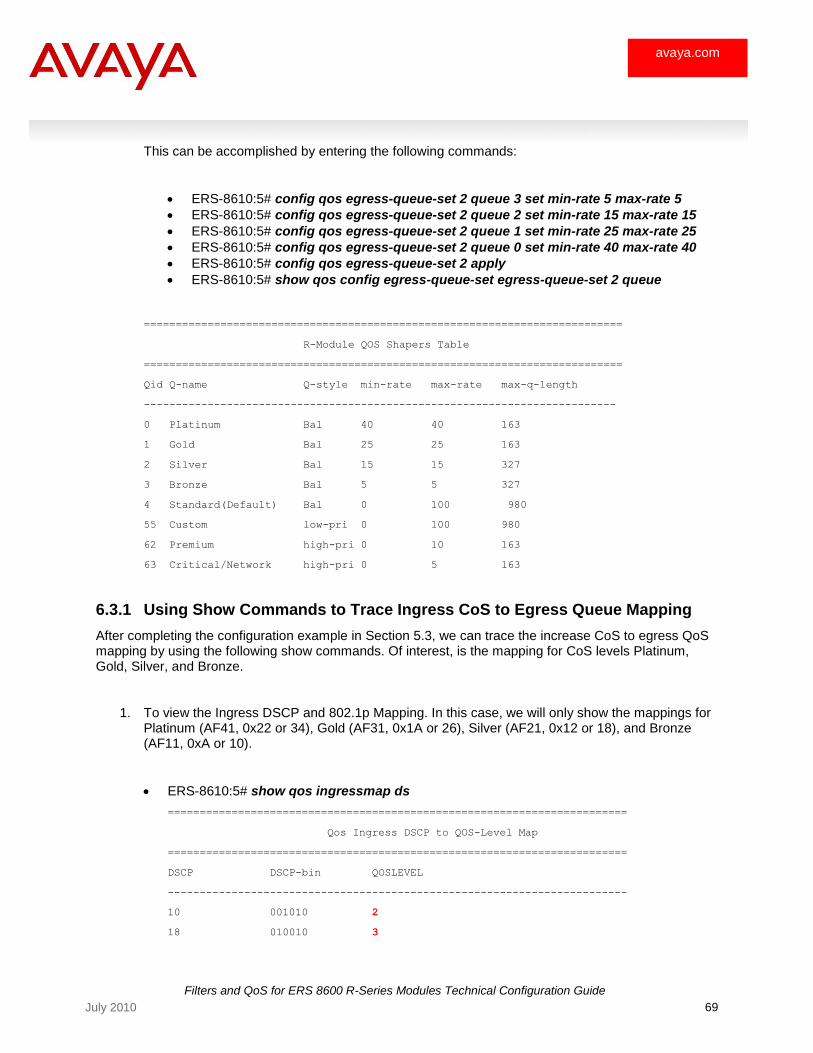
Filters and QoS for ERS 8600 R-Series Modules Technical Configuration Guide
69 July 2010
avaya.com
This can be accomplished by entering the following commands:
ERS-8610:5# config qos egress-queue-set 2 queue 3 set min-rate 5 max-rate 5
ERS-8610:5# config qos egress-queue-set 2 queue 2 set min-rate 15 max-rate 15
ERS-8610:5# config qos egress-queue-set 2 queue 1 set min-rate 25 max-rate 25
ERS-8610:5# config qos egress-queue-set 2 queue 0 set min-rate 40 max-rate 40
ERS-8610:5# config qos egress-queue-set 2 apply
ERS-8610:5# show qos config egress-queue-set egress-queue-set 2 queue
===========================================================================
R-Module QOS Shapers Table
===========================================================================
Qid Q-name Q-style min-rate max-rate max-q-length
--------------------------------------------------------------------------
0 Platinum Bal 40 40 163
1 Gold Bal 25 25 163
2 Silver Bal 15 15 327
3 Bronze Bal 5 5 327
4 Standard(Default) Bal 0 100 980
55 Custom low-pri 0 100 980
62 Premium high-pri 0 10 163
63 Critical/Network high-pri 0 5 163
6.3.1 Using Show Commands to Trace Ingress CoS to Egress Queue Mapping
After completing the configuration example in Section 5.3, we can trace the increase CoS to egress QoS mapping by using the following show commands. Of interest, is the mapping for CoS levels Platinum, Gold, Silver, and Bronze.
1. To view the Ingress DSCP and 802.1p Mapping. In this case, we will only show the mappings for Platinum (AF41, 0x22 or 34), Gold (AF31, 0x1A or 26), Silver (AF21, 0x12 or 18), and Bronze (AF11, 0xA or 10).
ERS-8610:5# show qos ingressmap ds
========================================================================
Qos Ingress DSCP to QOS-Level Map
========================================================================
DSCP DSCP-bin QOSLEVEL
------------------------------------------------------------------------
10 001010 2
18 010010 3
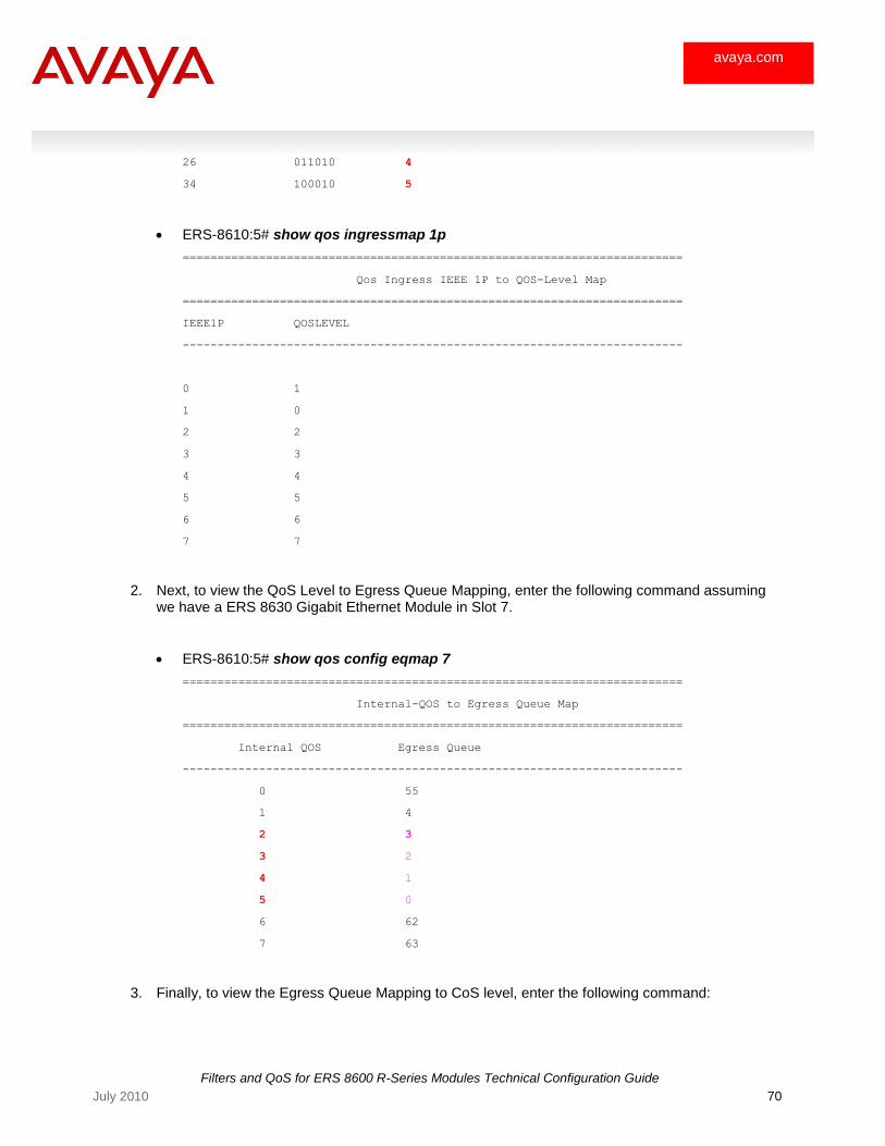
Filters and QoS for ERS 8600 R-Series Modules Technical Configuration Guide
70 July 2010
avaya.com
26 011010 4
34 100010 5
ERS-8610:5# show qos ingressmap 1p
========================================================================
Qos Ingress IEEE 1P to QOS-Level Map
========================================================================
IEEE1P QOSLEVEL
------------------------------------------------------------------------
0 1
1 0
2 2
3 3
4 4
5 5
6 6
7 7
2. Next, to view the QoS Level to Egress Queue Mapping, enter the following command assuming we have a ERS 8630 Gigabit Ethernet Module in Slot 7.
ERS-8610:5# show qos config eqmap 7
========================================================================
Internal-QOS to Egress Queue Map
========================================================================
Internal QOS Egress Queue
------------------------------------------------------------------------
0 55
1 4
2 3
3 2
4 1
5 0
6 62
7 63
3. Finally, to view the Egress Queue Mapping to CoS level, enter the following command:
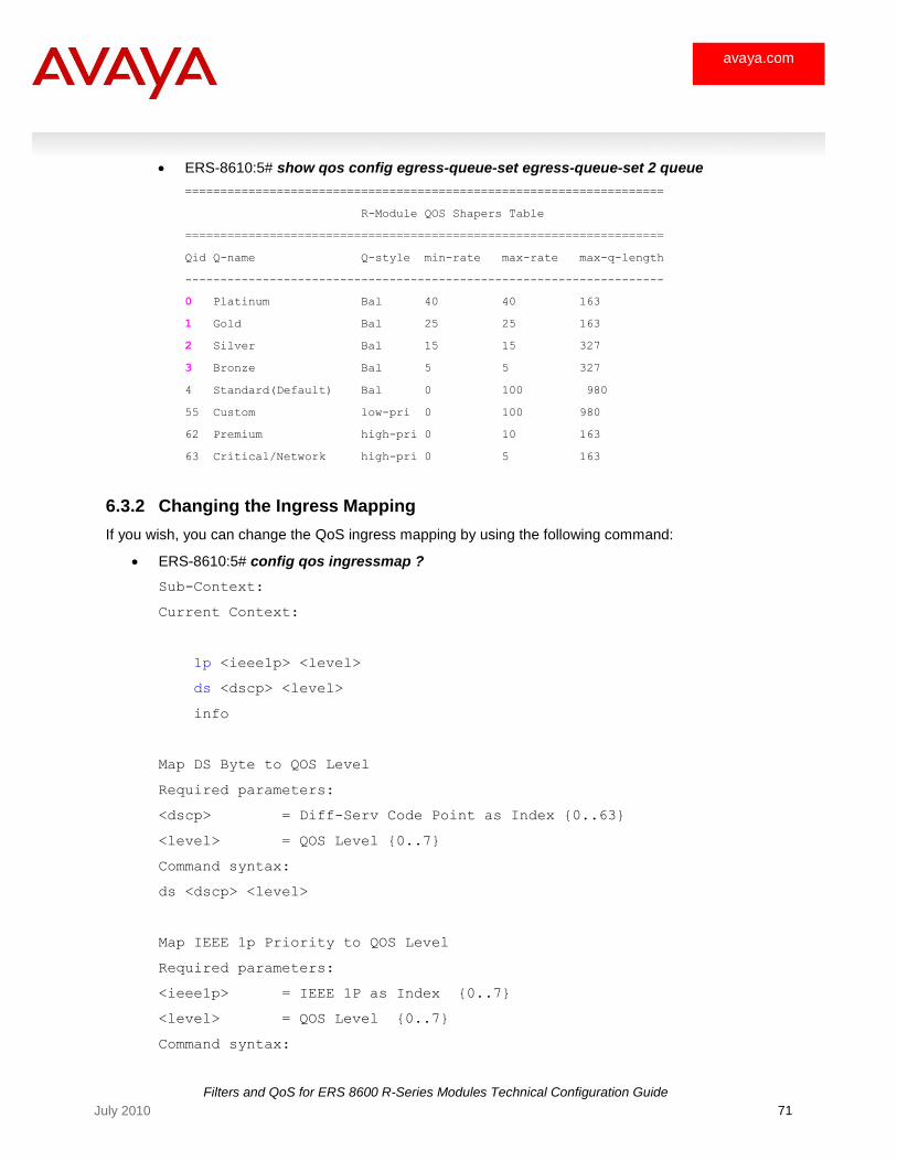
Filters and QoS for ERS 8600 R-Series Modules Technical Configuration Guide
71 July 2010
avaya.com
ERS-8610:5# show qos config egress-queue-set egress-queue-set 2 queue
====================================================================
R-Module QOS Shapers Table
====================================================================
Qid Q-name Q-style min-rate max-rate max-q-length
--------------------------------------------------------------------
0 Platinum Bal 40 40 163
1 Gold Bal 25 25 163
2 Silver Bal 15 15 327
3 Bronze Bal 5 5 327
4 Standard(Default) Bal 0 100 980
55 Custom low-pri 0 100 980
62 Premium high-pri 0 10 163
63 Critical/Network high-pri 0 5 163
6.3.2 Changing the Ingress Mapping
If you wish, you can change the QoS ingress mapping by using the following command:
ERS-8610:5# config qos ingressmap ?
Sub-Context:
Current Context:
1p <ieee1p> <level>
ds <dscp> <level>
info
Map DS Byte to QOS Level
Required parameters:
<dscp> = Diff-Serv Code Point as Index {0..63}
<level> = QOS Level {0..7}
Command syntax:
ds <dscp> <level>
Map IEEE 1p Priority to QOS Level
Required parameters:
<ieee1p> = IEEE 1P as Index {0..7}
<level> = QOS Level {0..7}
Command syntax:
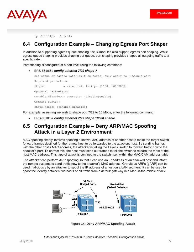
Filters and QoS for ERS 8600 R-Series Modules Technical Configuration Guide
72 July 2010
avaya.com
1p <ieee1p> <level>
6.4 Configuration Example – Changing Egress Port Shaper
In addition to supporting egress queue shaping, the R-modules also support egress port shaping. While egress queue shaping provides shaping per queue, port shaping provides shapes all outgoing traffic to a specific rate.
Port shaping is configured at a port level using the following command:
ERS-8610:5# config ethernet 7/29 shape ?
set shape or egress-rate-limit on ports, only apply to R-module port
Required parameters:
<kbps> = rate limit in kbps {1000..10000000}
Optional parameters:
<enable|disable> = operation {disable|enable}
Command syntax:
shape <kbps> [<enable|disable>]
For example, assuming we wish to shape port 7/29 to 10 Mbps, enter the following command:
ERS-8610:5# config ethernet 7/29 shape 10000 enable
6.5 Configuration Example – Deny ARP/MAC Spoofing Attack in a Layer 2 Environment
MAC spoofing simply involves spoofing a known MAC address of another host to make the target switch forward frames destined for the remote host to be forwarded to the attackers host. By sending frames with the other host‘s MAC address, the attacker is telling the Layer 2 switch to forward traffic now to the attacker‘s port. To correct this, the host must send out frames to tell the switch to relearn the most of the host MAC address. This type of attack is confined to the switch itself within the MAC/CAM address table
The attacker can perform ARP spoofing so that it can use an IP address of an attacked host and inform the remote systems to send traffic now to the attacker‘s MAC address. Gratuitous ARPs (gARP) can be used maliciously by an attacker to spoof the IP address of a host on a LAN segment. It can be used to spoof the identity between two hosts or all traffic from a default gateway in a Man-in-the-middle attack.
Figure 14: Deny ARP/MAC Spoofing Attack
Filters and QoS for ERS 8600 R-Series Modules Technical Configuration Guide
73 July 2010
avaya.com
In this configuration example:
PP8600A is configured with VLAN 2 with port members 7/26 to 7/30
We will add an ACL to access ports 7/26 to 7/29 to prevent ARP/MAC man-in-the-middle attack
Basically, an ACL has to be setup to perform the following on all access ports:
a. Allow ARP requests as long as the dst MAC is a broadcast address
b. Deny gARP with an ARP response using the default gateway address as either the src IP or dst IP in a ARP response packet. This prevents an Attacker from spoofing the victims IP address to the default gateway and default gateways address to a victim
c. Allow ARP response as the last ACL action
To add an ACL to prevent an ARP/MAC man-in-the-middle attack, perform the following steps. For this example, by default, a pre-defined ACT has already been setup for ARP/MAC spoofing using ACT 4083. This can be verified by using the ‗show filter act‘ or ‗show filter act 4083‘ commands. To view the ACT pattern, use the command ‗show filter act-pattern 4083‘.
Note that the ACT pattern p1 and p2 uses a base pattern of ether-begin. Ether-begin refer to the beginning of an Ethernet packet. Next, notice that p1 is configured with an offset of 224 bits and an offset length of 32 bits. This offset allows us to filter on the src IP in an ARP packet. Finally, notice that p2 is configured with an offset of 224 bits and an offset length of 32 bits. This offset pattern allows us to filter on the dst IP in and ARP packet.
6.5.1 Via CLI
A. Create ACL 1
1. Create ACL 1 with type of inPort using ACT id 4083
ERS-8610:5# config filter acl 1 create inPort act 4083
2. Add Access ports to ACL 1
ERS-8610:5# config filter acl 1 port add 7/26-7/29
B. Add ACE‘s to ACL 1
1. Add ACE 1 with action of permit to allow ARP request‘s with a broadcast address as the dst MAC
ERS-8610:5# config filter acl 1 ace 1 action permit
ERS-8610:5# config filter acl 1 ace 1 ethernet dst-mac eq ff:ff:ff:ff:ff:ff
ERS-8610:5# config filter acl 1 ace 1 arp operation eq arprequest
ERS-8610:5# config filter acl 1 ace 1 enable
2. Add ACE 2 with action of deny to drop any ARP requests and enable statistics
ERS-8610:5# config filter acl 1 ace 2 action deny
ERS-8610:5# config filter acl 1 ace 2 debug count enable
ERS-8610:5# config filter acl 1 ace 2 arp operation eq arprequest
ERS-8610:5# config filter acl 1 ace 2 enable
3. Add ACE 3 with action of deny to drop any ARP response with a source address of the default gateway. Note the name p1; this is the ACT pattern name as explained above and used for pattern 1. Also note that the IP address is entered in Hex.
ERS-8610:5# config filter acl 1 ace 3 action deny
ERS-8610:5# config filter acl 1 ace 3 debug count enable
ERS-8610:5# config filter acl 1 ace 3 advanced custom-filter1 p1 eq 0a011901
Filters and QoS for ERS 8600 R-Series Modules Technical Configuration Guide
74 July 2010
avaya.com
ERS-8610:5# config filter acl 1 ace 3 enable
4. Add ACE 4 with action of deny to drop any ARP response with a destination address of the default gateway. Note the name p2; this is the ACT pattern name as explained above and used for pattern 2. Also note that the IP address is entered in Hex.
ERS-8610:5# config filter acl 1 ace 4 action deny
ERS-8610:5# config filter acl 1 ace 4 debug count enable
ERS-8610:5# config filter acl 1 ace 4 advanced custom-filter2 p2 eq 0a011901
ERS-8610:5# config filter acl 1 ace 4 enable
5. Add ACE 5 with action of permit to allow all other ARP responses.
ERS-8610:5# config filter acl 1 ace 5 action permit
ERS-8610:5# config filter acl 1 ace 5 arp operation eq arpresponse
ERS-8610:5# config filter acl 1 ace 5 enable
6.5.2 Via JDM
A. Create ACL 1
Create a new ACL with type of inPort using ACT ID 1
1. Go to Security, select Advanced L2-L7 Filter and then click on ACL. Click on the OK button when prompted with the ‗NOTE: Filter configuration of R-modules only‘ icon. Unless you wish to change the GrId and Policy Name, leave the default setting of 1 and POLICY-1 respectively.
2. Via the ACL tab, click on Insert. Unless you wish to change the ACL id, leave the default setting which should default to 1 if this is the first ACL configured. Next enter the following:
ActId: 4083
Type: inPort
PortList: 7/26-7/29
Click on Insert when finished.
B. Add ACE‘s to ACL 1
1. Add ACE 1 with action of action of permit to allow ARP request‘s with a broadcast address as the dst MAC.
Start by clicking on AclId 1and then clicking on ACE via the ACL tab in the ACL window. Next, click on Insert. The default AceId should be 1. If you do not enter a name, a default name of ACE-1 will be used. Hence, do not enter anything in the AceId and Name windows. Next, enter the following:
Mode: permit
Click on Insert when completed
Setup Ethernet dst address
Via the ACE Common tab, highlight AceId 1, click on Eth and click on Destination Address tab. Click on Insert and enter the following:
Oper: eq
List: ff:ff:ff:ff:ff:ff
Click on Insert when completed
Setup ARP Request
Filters and QoS for ERS 8600 R-Series Modules Technical Configuration Guide
75 July 2010
avaya.com
Via the ACE Common tab, highlight AceId 1, click on Arp and click on Insert tab. Click on Insert and enter the following:
Type: operation
Oper: eq
Value: arpRequest
Click on Insert when completed
2. Add ACE 2 with action of deny to drop all other ARP request‘s and enable statistics
Start by clicking on Insert via the ACE Common tab. The default AceId should be 2. If you do not enter a name, a default name of ACE-2 will be used. Hence, do not enter anything in the AceId and Name windows. Next, enter the following:
Mode: deny
Flags: Count
Click on Insert to complete ACE 2 configuration
Select ARP Request
Via the ACE Common tab with ACE-2 selected, click on Arp. Click on Insert and enter the following:
Type: operation
Oper: eq
Value: arpRequest
Click on Insert when completed
3. Add ACE 3 with action of deny to drop any ARP response with a source address of the default gateway. Note the name p1; this is the ACT pattern name as explained above and used for pattern 1. Also note that the IP address is entered in Hex.
Start by clicking on Insert via the ACE Common tab. The default AceId should be 3. If you do not enter a name, a default name of ACE-3 will be used. Hence, do not enter anything in the AceId and Name windows. Next, enter the following:
Mode: deny
Flags: Count
Click on Insert to complete ACE 3 configuration
Select ACT data pattern p1
Via the ACE Common tab with ACE-3 selected, click on Adv. Click on Pattern 1 and then Insert and enter the following:
Name: p1
Oper: eq
Value: 0a011901
Click on Insert when completed
4. Add ACE 4 with action of deny to drop any ARP response with a source address of the default gateway. Note the name p2; this is the ACT pattern name as explained above and used for pattern 2. Also note that the IP address is entered in Hex.

Filters and QoS for ERS 8600 R-Series Modules Technical Configuration Guide
76 July 2010
avaya.com
Start by clicking on Insert via the ACE Common tab. The default AceId should be 4. If you do not enter a name, a default name of ACE-4 will be used. Hence, do not enter anything in the AceId and Name windows. Next, enter the following:
Mode: deny
Flags: Count
Click on Insert to complete ACE 4 configuration
Select ACT data pattern p2
Via the ACE Common tab with ACE-4 selected, click on Adv. Click on Pattern 2 and then Insert and enter the following:
Name: p2
Oper: eq
Value: 0a011901
Click on Insert when completed
5. Add ACE 5 with action of permit to allow all other ARP responses.
Start by clicking on Insert via the ACE Common tab. The default AceId should be 5. If you do not enter a name, a default name of ACE-5 will be used. Hence, do not enter anything in the AceId and Name windows. Next, enter the following:
Mode: permit
Click on Insert to complete ACE 2 configuration
Select ARP Response
Via the ACE Common tab with ACE-5 selected, click on Arp. Click on Insert and enter the following:
Type: operation
Oper: eq
Value: arpResponse
Click on Insert when completed
C. Enable all ACE‘s
Via the ACE Common tab, make sure all ACE‘s are enabled via the AdminState tab.
6.6 Configuration Example – DoS Attacks
In this configuration example, we will use both offset and normal filters to deny various DoS attacks. Although there are many DoS attacks, but for this example, we will concentrate on the following:
SQLslam o The worm targeting SQL Server computers is self-propagating malicious code that exploits
the vulnerability described in VU#484891 (CAN-2002-0649). This vulnerability allows for the execution of arbitrary code on the SQL Server computer due to a stack buffer overflow. Once the worm compromises a machine, it will try to propagate itself. The worm will craft packets of 376-bytes and send them to randomly chosen IP addresses on port 1434/udp. If the packet is sent to a vulnerable machine, this victim machine will become infected and will also begin to
Filters and QoS for ERS 8600 R-Series Modules Technical Configuration Guide
77 July 2010
avaya.com
propagate. Beyond the scanning activity for new hosts, the current variant of this worm has no other payload. Activity of this worm is readily identifiable on a network by the presence of 376-byte UDP packets. These packets will appear to be originating from seemingly random IP addresses and destined for port 1434/udp.
Nachia o The W32/Nachi variants W32/Nachi-A and W32/Nachi-B are worms that spread using the
RPC DCOM vulnerability in a similar fashion to the W32/Blaster-A worm. Both rely upon two vulnerabilities in Microsoft's software.
Xmas o This is a DoS attack that sends TCP packets with TCP Flags URG, PSH, and FIN set in the
same packet which is illegal.
TCP SynFinScan o This is a DoS attack that sends both a TCP SYN and FIN in the same packet which is illegal.
TCP FtpPort o These are TCP packets with a source port of 20 (FTP) and a destination port less than 1024
which is illegal. A legal FTP request would have been initiated with a TCP port greater than 1024.
TCP DnsPort o Similar to TCP FtpPort above but for DNS port 53. Note that this is for TCP DNS.
To configure the above, please follow the steps below. For this example, we will assume the following:
Use ACT 1 with two off-set patterns for SQLslam and Nachia
Use ACL 4
Apply the ACL 4 to VLAN 2.
6.6.1 Via CLI
A. Create a new ACT to filter on src-IP, dst-IP, IP Protocol Type, TCP src port, TCP dst port, UDP dst port, and TCP Flags. Also add off-set pattern location.
1. Create a new ACT with ID = 1
ERS-8610:5# config filter act 1 create
2. Select IP attributes of source IP, destination IP, and IP protocol type
ERS-8610:5# config filter act 1 ip srcIp,dstIp, ipProtoType
3. Select Protocol Attributes of TCP source port, TCP destination port, UDP destination port, and TCP flags
ERS-8610:5# config filter act 1 protocol tcpSrcPort,tcpDstPort, udpDstPort,tcpFlags
4. Add ACT pattern location for SQLslam. For this example, we will start at the beginning of the IP TOS field. The pattern we wish to filter on begins 216 bits (27 bytes, data field) from the beginning of the IP TOS field where the pattern length is 48 bits (6 bytes). We will name the pattern SQLslam. This name will be applied to an ACE with the actual pattern latter on.
ERS-8610:5# config filter act 1 pattern SQLslam add ip-tos-begin 216 48
5. Add ACT pattern location for Nachia. For this example, we will start at the beginning of the IP TOS field. The pattern we wish to filter on begins 224 bits (28 bytes) from the beginning of the IP
Filters and QoS for ERS 8600 R-Series Modules Technical Configuration Guide
78 July 2010
avaya.com
TOS field where the pattern length is 24 bits (3 bytes). This name will be applied to an ACE with the actual pattern latter on.
ERS-8610:5# config filter act 1 pattern Nachia add ip-tos-begin 224 24
6. Enable ACT 1
ERS-8610:5# config filter act 1 apply
B. Create ACL 4
1. Create ACL 4 with type of ingress VLAN:
ERS-8610:5# config filter acl 4 create inVlan act 1
2. Add VLAN 2 to ACL 1:
ERS-8610:5# config filter acl 4 add 2
C. Add ACE‘s to ACL 4
1. Add ACE 1 with action of deny stop-on-match for SQLslam and enable statistics. We will add the offset pattern of 040101010101 using ACT pattern named SQLslam configured in Step A, bullet 4 above. Note that we are adding the offset pattern to advanced custom filter 1. A maximum of up to three offset patterns are allowed per ACL.
ERS-8610:5# config filter acl 4 ace 1 create name "ACE-SQLslam"
ERS-8610:5# config filter acl 4 ace 1 action deny stop-on-match true
ERS-8610:5# config filter acl 4 ace 1 debug count enable
ERS-8610:5# config filter acl 4 ace 1 ip ip-protocol-type eq udp
ERS-8610:5# config filter acl 4 ace 1 protocol udp-dst-port eq 1434
ERS-8610:5# config filter acl 4 ace 1 advanced custom-filter1 SQLslam eq 040101010101
ERS-8610:5# config filter acl 4 ace 1 enable
2. Add ACE 2 with action of deny stop-on-match for Nachia and enable statistics. We will add the offset pattern of aaaaaa using ACT pattern named Nachia configured in Step A, bullet 5 above. Note that we are adding the offset pattern to advanced custom filter 2. A maximum of up to three offset patterns are allowed per ACL.
ERS-8610:5# config filter acl 4 ace 2 create name "ACE-Nachia"
ERS-8610:5# config filter acl 4 ace 2 action deny stop-on-match true
ERS-8610:5# config filter acl 4 ace 2 debug count enable
ERS-8610:5# config filter acl 4 ace 2 ip ip-protocol-type eq icmp
ERS-8610:5# config filter acl 4 ace 2 advanced custom-filter2 Nachia eq aaaaaa
ERS-8610:5# config filter acl 4 ace 2 enable
3. Add ACE 3 with action of deny stop-on-match for Xmas and enable statistics. We will filter of protocol type of TCP with TCP Flag set with Synchronize, Push, and Urgent.
ERS-8610:5# config filter acl 4 ace 3 create name "ACE-Xmas"
ERS-8610:5# config filter acl 4 ace 3 action deny stop-on-match true
ERS-8610:5# config filter acl 4 ace 3 debug count enable
ERS-8610:5# config filter acl 4 ace 3 ip ip-protocol-type eq tcp
ERS-8610:5# config filter acl 4 ace 3 protocol tcp-flags match-all fin,push,urg
ERS-8610:5# config filter acl 4 ace 3 enable
4. Add ACE 4 with action of deny stop-on-match for TCP SynFinScan and enable statistics. Here we will filter of protocol type of TCP with TCP Flag set with Synchronize and Finish.
Filters and QoS for ERS 8600 R-Series Modules Technical Configuration Guide
79 July 2010
avaya.com
ERS-8610:5# config filter acl 4 ace 4 create name "ACE-SynFinScan"
ERS-8610:5# config filter acl 4 ace 4 action deny stop-on-match true
ERS-8610:5# config filter acl 4 ace 4 debug count enable
ERS-8610:5# config filter acl 4 ace 4 ip ip-protocol-type eq tcp
ERS-8610:5# config filter acl 4 ace 4 protocol tcp-flags match-all fin,syn
ERS-8610:5# config filter acl 4 ace 4 enable
5. Add ACE 5 with action of deny stop-on-match for TCP FtpPort and enable statistics. Here we will filter of protocol type of TCP with TCP Flag set with Synchronize, TCP src port equals 20, and TCP dst port equal to or less than 1024.
ERS-8610:5# config filter acl 4 ace 5 create name "ACE-FtpPort"
ERS-8610:5# config filter acl 4 ace 5 action deny stop-on-match true
ERS-8610:5# config filter acl 4 ace 5 debug count enable
ERS-8610:5# config filter acl 4 ace 5 ip ip-protocol-type eq tcp
ERS-8610:5# config filter acl 4 ace 5 protocol tcp-src-port eq 20
ERS-8610:5# config filter acl 4 ace 5 protocol tcp-dst-port le 1024
ERS-8610:5# config filter acl 4 ace 5 protocol tcp-flags match-all syn
ERS-8610:5# config filter acl 4 ace 5 enable
6. Add ACE 6 with action of deny stop-on-match for TCP DnsPort and enable statistics. Here we will filter of protocol type of TCP with TCP Flag set with Synchronize, TCP src port equals 53, and TCP dst port equal to or less than 1024.
ERS-8610:5# config filter acl 4 ace 6 create name "ACE-DnsPort"
ERS-8610:5# config filter acl 4 ace 6 action deny stop-on-match true
ERS-8610:5# config filter acl 4 ace 6 debug count enable
ERS-8610:5# config filter acl 4 ace 6 ip ip-protocol-type eq tcp
ERS-8610:5# config filter acl 4 ace 6 protocol tcp-src-port eq 53
ERS-8610:5# config filter acl 4 ace 6 protocol tcp-dst-port le 1024
ERS-8610:5# config filter acl 4 ace 6 protocol tcp-flags match-all syn
ERS-8610:5# config filter acl 4 ace 6 enable
6.6.2 Via JDM
A. Create a new ACT to filter on src-IP, dst-IP, IP Protocol Type, TCP src port, TCP dst port, UDP dst port, and TCP Flags. Also add off-set pattern location.
Create a new ACL with type of inport using ACT ID 1
1. Go to Security, select Advanced L2-L7 Filter and then click on ACL. Click on the OK button when prompted with the ‗NOTE: Filter configuration of R-modules only‘ icon.
2. Via the ACT tab, click on Insert. Unless you wish to change the ACL id, leave the default setting which should default to 1 if this is the first ACL configured. Next enter the following:
IpAttrs: srcIp, dstIp, ipProtoType
ProtocolAttrs: tcpSrcPort, tcpDstPort, udpDstPort, tcpFlags
Click on Insert when finished
3. Via the ACT tab, select ACT-1 and click on Pattern. Via the Pattern window, click on Insert to add ACT pattern location for SQLslam. For this example, we will start at the beginning of the IP TOS field. The pattern we wish to filter on begins 216 bits (27 bytes, data field) from the beginning of the IP TOS field where the pattern length is 48 bits (6 bytes). We will name the pattern SQLslam. This name will be applied to an ACE with the actual pattern latter on. Enter the following:
Name: SQLslam
Filters and QoS for ERS 8600 R-Series Modules Technical Configuration Guide
80 July 2010
avaya.com
Base: ipTosBegin
Offset: 216
Length: 48
Click on Insert when finished
4. Via the Pattern window, click on Insert to add ACT pattern location for Nachia. For this example, we will start at the beginning of the IP TOS field. The pattern we wish to filter on begins 224 bits (28 bytes) from the beginning of the IP TOS field where the pattern length is 24 bits (3 bytes). This name will be applied to an ACE with the actual pattern latter on.
Name: Nachia
Base: ipTosBegin
Offset: 224
Length: 24
Click on Insert when finished
Via the Pattern window, click on Close to go back to the main ACT window
5. Enable ACT-1
Via the main ACT window, under the Apply tab for ACT-1, select true then click on Apply.
B. Create ACL 4
Create a new ACL using ACL ID 4 with type of inVlan using ACT ID 1
1. Go to Security, select Advanced L2-L7 Filter and then click on ACL.
2. Via the ACL tab, click on Insert. Next enter the following:
AclId: 4
ActId: 1
Type: inVlan
VlanList: 2
Click on Insert when finished.
C. Add ACE‘s to ACL 4
1. Add ACE 1 with action of deny stop-on-match for SQLslam and enable statistics. We will add the offset pattern of 040101010101 using ACT pattern named SQLslam configured in Step A, bullet 3 above. Note that we are adding the offset pattern to Pattern 1. A maximum of up to three offset patterns are allowed per ACL.
Start by clicking on AclId 4 and then clicking on ACE via the ACL tab in the ACL window. Next, click on Insert. The default AceId should be 1. Next, enter the following:
Name: ACE-SQLslam
Mode: deny
StopOnMatch: enable
Flags: count
Click on Insert when completed
Setup IP Protocol type of UDP
Via the ACE Common tab, highlight AceId 4, click on IP and Protocol tab. Click on Insert and enter the following:
Oper: eq
List: udp
Click on Insert when completed and then close

Filters and QoS for ERS 8600 R-Series Modules Technical Configuration Guide
81 July 2010
avaya.com
Setup UDP destination port equals 1434
Via the ACE Common tab, highlight AceId 4, click on Proto and UDP Destination Port tab. Click on Insert and enter the following:
Oper: eq
Port: 1434
Click on Insert and then close when completed
Setup offset pattern equals 040101010101
Via the ACE Common tab, highlight AceId 4, click on Adv, and select Pattern 1. Click on Insert and enter the following:
Name: SQLslam
Oper: eq
Value: 040101010101
Click on Insert and then close when completed
NOTE: The ACE name configured is the ACT pattern name configured above.
2. Add ACE 2 with action of deny stop-on-match for Nachia and enable statistics. We will add the offset pattern of aaaaaa using ACT pattern named Nachia configured in Step A, bullet 4 above. Note that we are adding the offset pattern to Pattern 2. A maximum of up to three offset patterns are allowed per ACL.
Via the ACE Common window, click on Insert. The default AceId should be 2. Next, enter the following:
Name: ACE-Nachia
Mode: deny
StopOnMatch: enable
Flags: count
Click on Insert when completed
Setup IP Protocol type of ICMP
Via the ACE Common tab, highlight AceId 4 AceId 2, click on IP and Protocol tab. Click on Insert and enter the following:
Oper: eq
List: icmp
Click on Insert when completed
Setup offset pattern 2 equals aaaaaa
Via the ACE Common tab, highlight AceId 4 AceId 2, click on Adv, and select Pattern 2. Click on Insert and enter the following:
Name: Nachia
Oper: eq
Value: aaaaaa
Click on Insert when completed
NOTE: The ACE name configured is the ACT pattern name configured above.
3. Add ACE 3 with action of deny stop-on-match for Xmas and enable statistics. We will filter on protocol type of TCP with TCP Flag set with Synchronize, Push, and Urgent.
Filters and QoS for ERS 8600 R-Series Modules Technical Configuration Guide
82 July 2010
avaya.com
Via the ACE Common window, click on Insert. The default AceId should be 3. Next, enter the following:
Name: ACE-Xmas
Mode: deny
StopOnMatch: enable
Flags: count
Click on Insert when completed
Setup IP Protocol type of TCP
Via the ACE Common tab, highlight AceId 4 AceId 3, click on IP and Protocol tab. Click on Insert and enter the following:
Oper: eq
List: tcp
Click on Insert when completed
Setup TCP Flags to select Push and URG
Via the ACE Common tab, highlight AceId 4 AceId 3, click on Proto, and select TCP Flags. Click on Insert and enter the following:
Oper: matchAll
List: push,urg
Click on Insert when completed
4. Add ACE 4 with action of deny stop-on-match for TCP SynFinScan and enable statistics. Here we will filter on protocol type of TCP with TCP Flag set with Synchronize and Finish.
Via the ACE Common window, click on Insert. The default AceId should be 4. Next, enter the following:
Name: ACE-SynFinScan
Mode: deny
StopOnMatch: enable
Flags: count
Click on Insert when completed
Setup IP Protocol type of TCP
Via the ACE Common tab, highlight AceId 4 AceId 4, click on IP and Protocol tab. Click on Insert and enter the following:
Oper: eq
List: tcp
Click on Insert when completed
Setup TCP Flags to select Push and URG
Via the ACE Common tab, highlight AceId 4 AceId 4, click on Proto, and select TCP Flags. Click on Insert and enter the following:
Oper: matchAll
List: fin,syn
Click on Insert when completed
5. Add ACE 5 with action of deny stop-on-match for TCP FtpPort and enable statistics. Here we will filter on protocol type of TCP with TCP Flag set with Synchronize, TCP src port equals 20, and TCP dst port equal to or less than 1024.
Filters and QoS for ERS 8600 R-Series Modules Technical Configuration Guide
83 July 2010
avaya.com
Via the ACE Common window, click on Insert. The default AceId should be 5. Next, enter the following:
Name: ACE-FtpPort
Mode: deny
StopOnMatch: enable
Flags: count
Click on Insert when completed
Setup IP Protocol type of TCP
Via the ACE Common tab, highlight AceId 4 AceId 5, click on IP and Protocol tab. Click on Insert and enter the following:
Oper: eq
List: tcp
Click on Insert when completed
Setup TCP source and destination ports
Via the ACE Common tab, highlight AceId 4 AceId 5, click on Proto, and select TCP Source Port. Click on Insert and enter the following:
Oper: eq
List: 20
Click on Insert when completed
Con‘t via the Proto tab, select TCP Destination Port. Click on Insert and enter the following:
Oper: eq
List: 1024
Click on Insert when completed
Setup TCP Flags to select SYN
Con‘t via the Proto tab, and select TCP Flags. Click on Insert and enter the following:
Oper: matchAll
List: syn
Click on Insert when completed
6. Add ACE 6 with action of deny stop-on-match for TCP DnsPort and enable statistics. Here we will filter on protocol type of TCP with TCP Flag set with Synchronize, TCP src port equals 53, and TCP dst port equal to or less than 1024.
Via the ACE Common window, click on Insert. The default AceId should be 6. Next, enter the following:
Name: ACE-DnsPort
Mode: deny
StopOnMatch: enable
Flags: count
Click on Insert when completed
Setup IP Protocol type of TCP
Via the ACE Common tab, highlight AceId 4 AceId 6, click on IP and Protocol tab. Click on Insert and enter the following:
Oper: eq
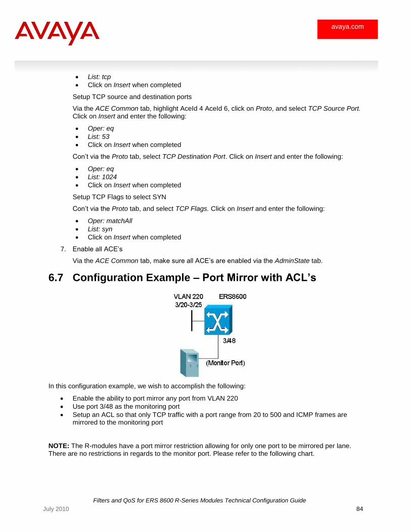
Filters and QoS for ERS 8600 R-Series Modules Technical Configuration Guide
84 July 2010
avaya.com
List: tcp
Click on Insert when completed
Setup TCP source and destination ports
Via the ACE Common tab, highlight AceId 4 AceId 6, click on Proto, and select TCP Source Port. Click on Insert and enter the following:
Oper: eq
List: 53
Click on Insert when completed
Con‘t via the Proto tab, select TCP Destination Port. Click on Insert and enter the following:
Oper: eq
List: 1024
Click on Insert when completed
Setup TCP Flags to select SYN
Con‘t via the Proto tab, and select TCP Flags. Click on Insert and enter the following:
Oper: matchAll
List: syn
Click on Insert when completed
7. Enable all ACE‘s
Via the ACE Common tab, make sure all ACE‘s are enabled via the AdminState tab.
6.7 Configuration Example – Port Mirror with ACL’s
In this configuration example, we wish to accomplish the following:
Enable the ability to port mirror any port from VLAN 220
Use port 3/48 as the monitoring port
Setup an ACL so that only TCP traffic with a port range from 20 to 500 and ICMP frames are mirrored to the monitoring port
NOTE: The R-modules have a port mirror restriction allowing for only one port to be mirrored per lane. There are no restrictions in regards to the monitor port. Please refer to the following chart.
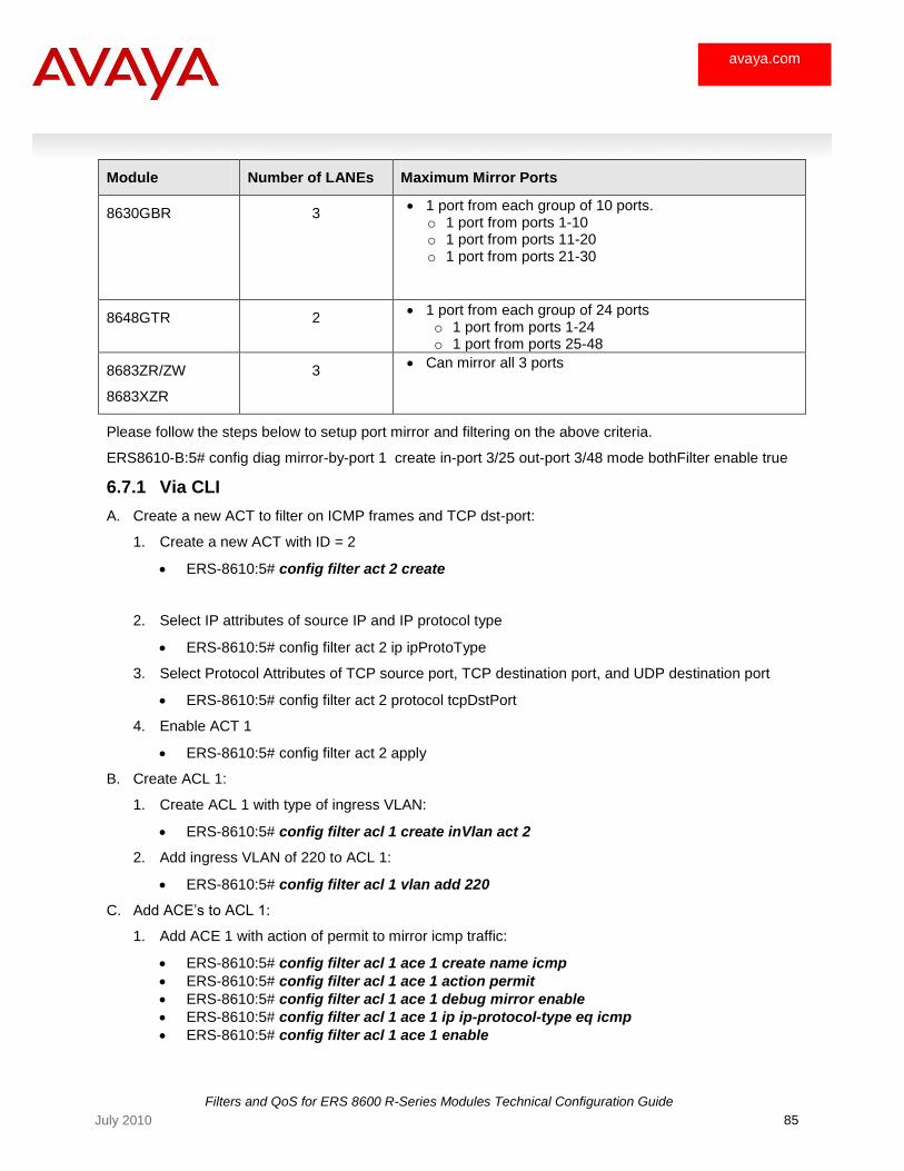
Filters and QoS for ERS 8600 R-Series Modules Technical Configuration Guide
85 July 2010
avaya.com
Module Number of LANEs Maximum Mirror Ports
8630GBR 3 1 port from each group of 10 ports.
o 1 port from ports 1-10 o 1 port from ports 11-20 o 1 port from ports 21-30
8648GTR 2 1 port from each group of 24 ports
o 1 port from ports 1-24 o 1 port from ports 25-48
8683ZR/ZW
8683XZR
3 Can mirror all 3 ports
Please follow the steps below to setup port mirror and filtering on the above criteria.
ERS8610-B:5# config diag mirror-by-port 1 create in-port 3/25 out-port 3/48 mode bothFilter enable true
6.7.1 Via CLI
A. Create a new ACT to filter on ICMP frames and TCP dst-port:
1. Create a new ACT with ID = 2
ERS-8610:5# config filter act 2 create
2. Select IP attributes of source IP and IP protocol type
ERS-8610:5# config filter act 2 ip ipProtoType
3. Select Protocol Attributes of TCP source port, TCP destination port, and UDP destination port
ERS-8610:5# config filter act 2 protocol tcpDstPort
4. Enable ACT 1
ERS-8610:5# config filter act 2 apply
B. Create ACL 1:
1. Create ACL 1 with type of ingress VLAN:
ERS-8610:5# config filter acl 1 create inVlan act 2
2. Add ingress VLAN of 220 to ACL 1:
ERS-8610:5# config filter acl 1 vlan add 220
C. Add ACE‘s to ACL 1:
1. Add ACE 1 with action of permit to mirror icmp traffic:
ERS-8610:5# config filter acl 1 ace 1 create name icmp
ERS-8610:5# config filter acl 1 ace 1 action permit
ERS-8610:5# config filter acl 1 ace 1 debug mirror enable
ERS-8610:5# config filter acl 1 ace 1 ip ip-protocol-type eq icmp
ERS-8610:5# config filter acl 1 ace 1 enable
Filters and QoS for ERS 8600 R-Series Modules Technical Configuration Guide
86 July 2010
avaya.com
2. Add ACE 2 with action of permit to mirror TCP traffic with a destination port range from 20 to 500
ERS-8610:5# config filter acl 1 ace 2 create name tcp_range
ERS-8610:5# config filter acl 1 ace 2 action permit
ERS-8610:5# config filter acl 1 ace 2 debug mirror enable
ERS-8610:5# config filter acl 1 ace 2 ip ip-protocol-type eq tcp
ERS-8610:5# config filter acl 1 ace 2 protocol tcp-dst-port eq 20-500
ERS-8610:5# config filter acl 1 ace 2 enable
D. Enable port mirror:
ERS-8610:5# config diag mirror-by-port 1 create in-port 3/25 out-port 3/48 mode bothFilter enable true
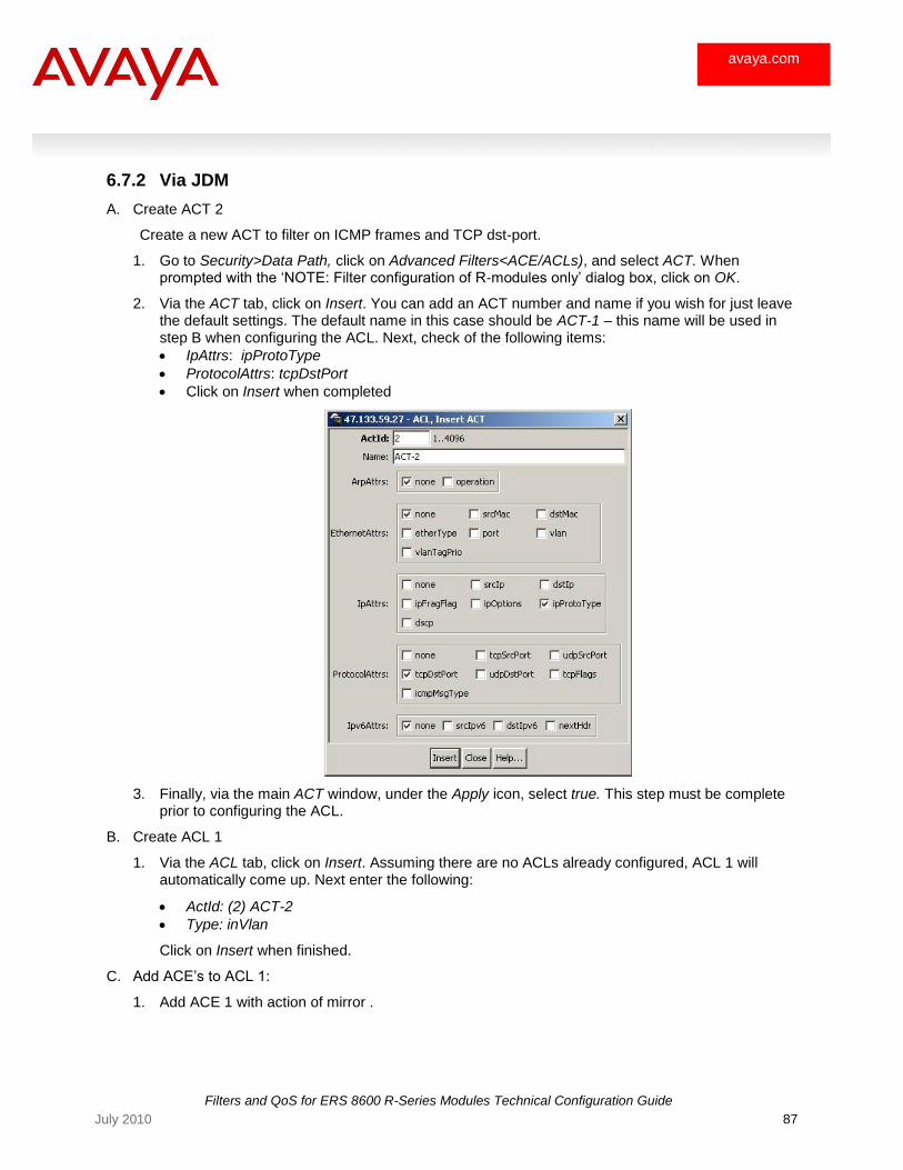
Filters and QoS for ERS 8600 R-Series Modules Technical Configuration Guide
87 July 2010
avaya.com
6.7.2 Via JDM
A. Create ACT 2
Create a new ACT to filter on ICMP frames and TCP dst-port.
1. Go to Security>Data Path, click on Advanced Filters<ACE/ACLs), and select ACT. When prompted with the ‗NOTE: Filter configuration of R-modules only‘ dialog box, click on OK.
2. Via the ACT tab, click on Insert. You can add an ACT number and name if you wish for just leave the default settings. The default name in this case should be ACT-1 – this name will be used in step B when configuring the ACL. Next, check of the following items:
IpAttrs: ipProtoType
ProtocolAttrs: tcpDstPort
Click on Insert when completed
3. Finally, via the main ACT window, under the Apply icon, select true. This step must be complete prior to configuring the ACL.
B. Create ACL 1
1. Via the ACL tab, click on Insert. Assuming there are no ACLs already configured, ACL 1 will automatically come up. Next enter the following:
ActId: (2) ACT-2
Type: inVlan
Click on Insert when finished.
C. Add ACE‘s to ACL 1:
1. Add ACE 1 with action of mirror .
Filters and QoS for ERS 8600 R-Series Modules Technical Configuration Guide
88 July 2010
avaya.com
Start by clicking on AclId 1and then clicking on ACE via the ACL tab in the ACL window. Next, click on Insert. The default AceId should be 1. If you do not enter a name, a default name of ACE-1 will be used. Next, enter the following:
AceId: 1
Name: icmp
Mode: permit
Flags: mirror
Click on Insert to complete ACE 1 configuration
Select protocol type icmp
Via the ACE Common tab, highlight AceId 1, click on IP and click on Protocol tab. Click on Insert and enter the following:
Oper: eq
List: icmp
Click on Insert when completed
2. Add ACE 2 with action of mirror.
Start by clicking on Insert via the ACE Common tab. The default AceId should be 2. Next, enter the following:
AceId: 2
Name: tcp_range
Mode: permit
Flags: mirror
Click on Insert to complete ACE 2 configuration
Select protocol type TCP
Via the ACE Common tab, highlight AceId 2, click on IP and click on Protocol tab. Click on Insert and enter the following:
Oper: eq
List: tcp
Click on Insert when completed
Add TCP port range
Via the ACE Common tab, highlight AceId 2, click on Proto and click on TCP Destination Port tab. Click on Insert and enter the following:
Oper: eq
Port: 20-500
Click on Insert when completed
Next, make sure you enable ACE 1 and ACE 2 by selecting enable under the AdminState window.
Filters and QoS for ERS 8600 R-Series Modules Technical Configuration Guide
89 July 2010
avaya.com
7. Appendix A – Configuration Files
7.1 From Example 6.1
#
# R-MODULE FILTER CONFIGURATION
#
filter act 1 create
filter act 1 ip srcIp,ipProtoType
filter act 1 protocol tcpSrcPort,tcpDstPort,udpDstPort
filter act 1 apply
filter acl 1 create inVlan act 1
filter acl 1 vlan add 200
filter acl 1 ace 1 action deny stop-on-match true
filter acl 1 ace 1 debug count enable
filter acl 1 ace 1 ip ip-protocol-type eq udp
filter acl 1 ace 1 protocol udp-dst-port eq tftp
filter acl 1 ace 1 enable
filter acl 1 ace 2 action permit remark-dscp phbcs2 stop-on-match true
filter acl 1 ace 2 debug count enable
filter acl 1 ace 2 ip src-ip eq 10.1.1.2-10.1.1.3
filter acl 1 ace 2 ip ip-protocol-type eq tcp
filter acl 1 ace 2 protocol tcp-src-port eq 80
filter acl 1 ace 2 enable
filter acl 1 ace 3 action deny stop-on-match true
filter acl 1 ace 3 debug count enable
filter acl 1 ace 3 ip ip-protocol-type eq tcp
filter acl 1 ace 3 protocol tcp-src-port eq 80
filter acl 1 ace 3 enable
filter acl 1 ace 4 action permit remark-dscp phbcs1 stop-on-match true
filter acl 1 ace 4 debug count enable
filter acl 1 ace 4 ip src-ip ge 0.0.0.0
filter acl 1 ace 4 enable
Filters and QoS for ERS 8600 R-Series Modules Technical Configuration Guide
90 July 2010
avaya.com
7.2 From Example 6.2
#
# QOS CONFIGURATION
#
qos policy 1 create peak-rate 2000 svc-rate 1000 lanes 7/3 name "POLICY-1"
#
# VLAN CONFIGURATION
#
vlan 1 ports remove 4/1-4/30,7/1-7/30 member portmember
vlan 2 create byport 1 color 1
vlan 2 ports remove 4/1-4/30,7/1-7/28 member portmember
vlan 2 ports add 7/29-7/30 member portmember
#
# R-MODULE FILTER CONFIGURATION
#
filter act 1 create
filter act 1 protocol tcpDstPort,udpDstPort
filter act 1 apply
filter acl 1 create inVlan act 1
filter acl 1 vlan add 2
filter acl 1 ace 1 create name "UDP_Range"
filter acl 1 ace 1 action permit remark-dscp phbaf41
filter acl 1 ace 1 debug count enable
filter acl 1 ace 1 protocol udp-dst-port eq 1124-1784
filter acl 1 ace 1 enable
filter acl 1 ace 2 create name "Police_1"
filter acl 1 ace 2 action permit remark-dscp phbaf11 police 1
filter acl 1 ace 2 debug count enable
filter acl 1 ace 2 protocol tcp-dst-port eq 20-21
filter acl 1 ace 2 enable
Filters and QoS for ERS 8600 R-Series Modules Technical Configuration Guide
91 July 2010
avaya.com
7.3 From Example 6.3
#
# QOS CONFIGURATION
#
qos egress-queue-set 2 queue 0 set min-rate 40
qos egress-queue-set 2 queue 1 set min-rate 25
qos egress-queue-set 2 queue 2 set min-rate 15
qos egress-queue-set 2 queue 3 set min-rate 5
qos egress-queue-set 2 queue 4 set min-rate 0
qos egress-queue-set 2 queue 62 set max-rate 10
qos egress-queue-set 2 apply
7.4 From Example 6.4
#
# R-MODULE FILTER CONFIGURATION
#
filter acl 1 create inPort act 4083
filter acl 1 port add 7/26-7/29
filter acl 1 ace 1 action permit
filter acl 1 ace 1 ethernet dst-mac eq ff:ff:ff:ff:ff:ff
filter acl 1 ace 1 arp operation eq arprequest
filter acl 1 ace 1 enable
filter acl 1 ace 2 action deny
filter acl 1 ace 2 debug count enable
filter acl 1 ace 2 arp operation eq arprequest
filter acl 1 ace 2 enable
filter acl 1 ace 3 action deny
filter acl 1 ace 3 debug count enable
filter acl 1 ace 3 advanced custom-filter1 p1 eq 0a011901
filter acl 1 ace 3 enable
filter acl 1 ace 4 action deny
filter acl 1 ace 4 debug count enable
filter acl 1 ace 4 advanced custom-filter2 p2 eq 0a011901
filter acl 1 ace 4 enable
filter acl 1 ace 5 action permit
filter acl 1 ace 5 arp operation eq arpresponse
filter acl 1 ace 5 enable
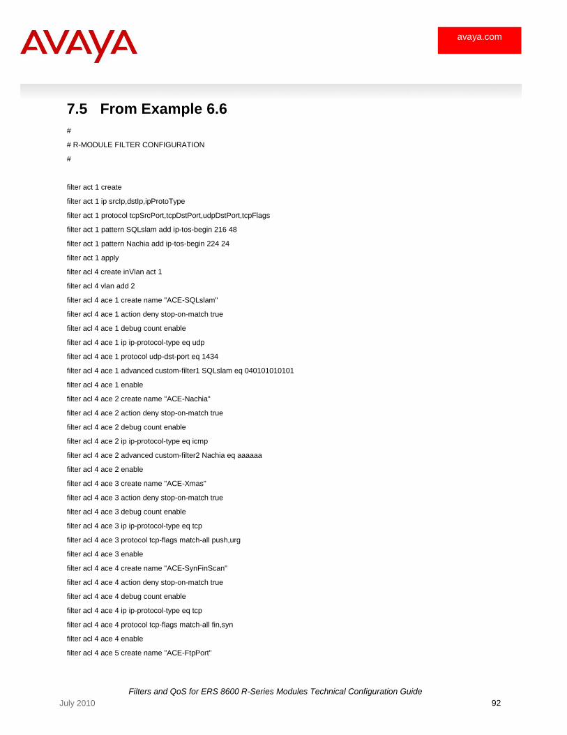
Filters and QoS for ERS 8600 R-Series Modules Technical Configuration Guide
92 July 2010
avaya.com
7.5 From Example 6.6
#
# R-MODULE FILTER CONFIGURATION
#
filter act 1 create
filter act 1 ip srcIp,dstIp,ipProtoType
filter act 1 protocol tcpSrcPort,tcpDstPort,udpDstPort,tcpFlags
filter act 1 pattern SQLslam add ip-tos-begin 216 48
filter act 1 pattern Nachia add ip-tos-begin 224 24
filter act 1 apply
filter acl 4 create inVlan act 1
filter acl 4 vlan add 2
filter acl 4 ace 1 create name "ACE-SQLslam"
filter acl 4 ace 1 action deny stop-on-match true
filter acl 4 ace 1 debug count enable
filter acl 4 ace 1 ip ip-protocol-type eq udp
filter acl 4 ace 1 protocol udp-dst-port eq 1434
filter acl 4 ace 1 advanced custom-filter1 SQLslam eq 040101010101
filter acl 4 ace 1 enable
filter acl 4 ace 2 create name "ACE-Nachia"
filter acl 4 ace 2 action deny stop-on-match true
filter acl 4 ace 2 debug count enable
filter acl 4 ace 2 ip ip-protocol-type eq icmp
filter acl 4 ace 2 advanced custom-filter2 Nachia eq aaaaaa
filter acl 4 ace 2 enable
filter acl 4 ace 3 create name "ACE-Xmas"
filter acl 4 ace 3 action deny stop-on-match true
filter acl 4 ace 3 debug count enable
filter acl 4 ace 3 ip ip-protocol-type eq tcp
filter acl 4 ace 3 protocol tcp-flags match-all push,urg
filter acl 4 ace 3 enable
filter acl 4 ace 4 create name "ACE-SynFinScan"
filter acl 4 ace 4 action deny stop-on-match true
filter acl 4 ace 4 debug count enable
filter acl 4 ace 4 ip ip-protocol-type eq tcp
filter acl 4 ace 4 protocol tcp-flags match-all fin,syn
filter acl 4 ace 4 enable
filter acl 4 ace 5 create name "ACE-FtpPort"
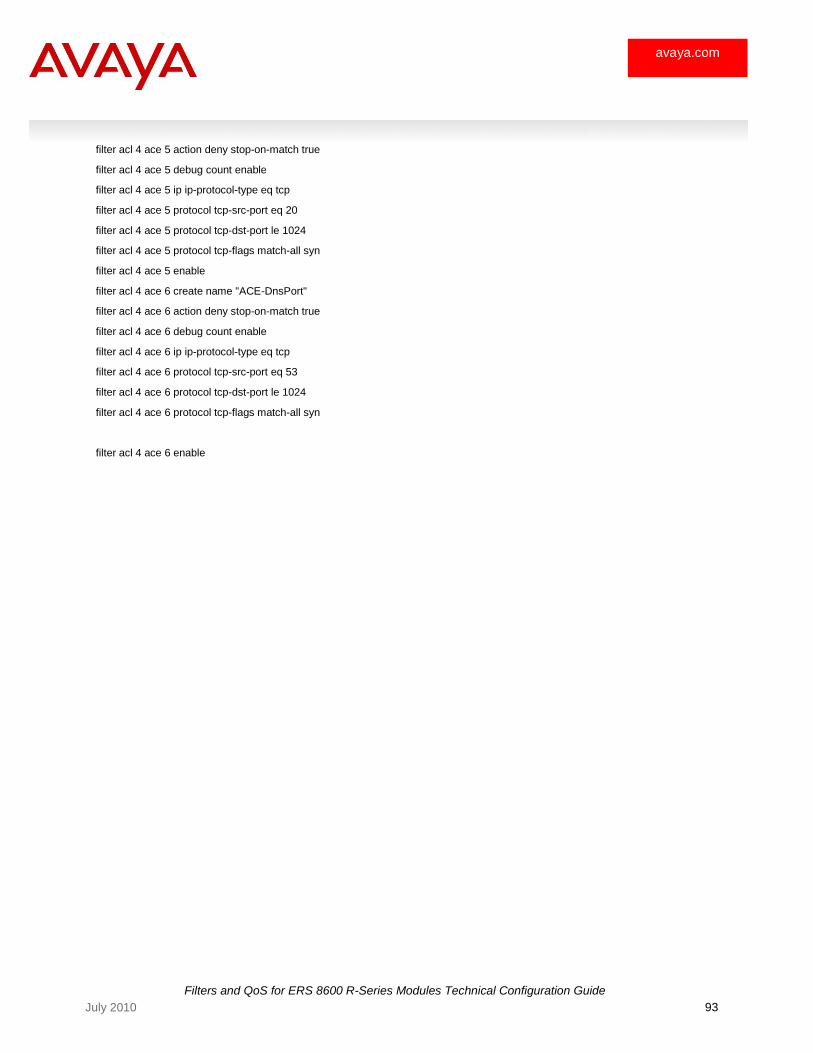
Filters and QoS for ERS 8600 R-Series Modules Technical Configuration Guide
93 July 2010
avaya.com
filter acl 4 ace 5 action deny stop-on-match true
filter acl 4 ace 5 debug count enable
filter acl 4 ace 5 ip ip-protocol-type eq tcp
filter acl 4 ace 5 protocol tcp-src-port eq 20
filter acl 4 ace 5 protocol tcp-dst-port le 1024
filter acl 4 ace 5 protocol tcp-flags match-all syn
filter acl 4 ace 5 enable
filter acl 4 ace 6 create name "ACE-DnsPort"
filter acl 4 ace 6 action deny stop-on-match true
filter acl 4 ace 6 debug count enable
filter acl 4 ace 6 ip ip-protocol-type eq tcp
filter acl 4 ace 6 protocol tcp-src-port eq 53
filter acl 4 ace 6 protocol tcp-dst-port le 1024
filter acl 4 ace 6 protocol tcp-flags match-all syn
filter acl 4 ace 6 enable
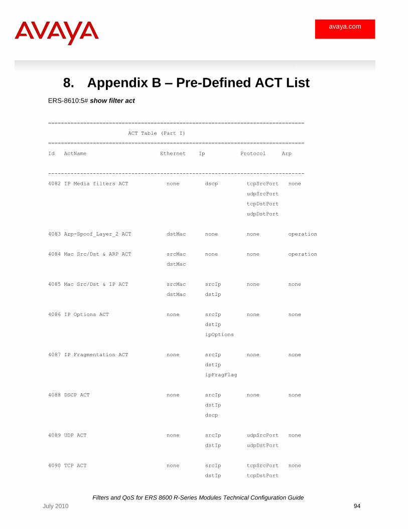
Filters and QoS for ERS 8600 R-Series Modules Technical Configuration Guide
94 July 2010
avaya.com
8. Appendix B – Pre-Defined ACT List
ERS-8610:5# show filter act
================================================================================
ACT Table (Part I)
================================================================================
Id ActName Ethernet Ip Protocol Arp
--------------------------------------------------------------------------------
4082 IP Media filters ACT none dscp tcpSrcPort none
udpSrcPort
tcpDstPort
udpDstPort
4083 Arp-Spoof_Layer_2 ACT dstMac none none operation
4084 Mac Src/Dst & ARP ACT srcMac none none operation
dstMac
4085 Mac Src/Dst & IP ACT srcMac srcIp none none
dstMac dstIp
4086 IP Options ACT none srcIp none none
dstIp
ipOptions
4087 IP Fragmentation ACT none srcIp none none
dstIp
ipFragFlag
4088 DSCP ACT none srcIp none none
dstIp
dscp
4089 UDP ACT none srcIp udpSrcPort none
dstIp udpDstPort
4090 TCP ACT none srcIp tcpSrcPort none
dstIp tcpDstPort

Filters and QoS for ERS 8600 R-Series Modules Technical Configuration Guide
95 July 2010
avaya.com
tcpFlags
4091 IP Sa/Da, Protocol ACT none srcIp none none
dstIp
ipProtoType
4092 IP Sa & Da ACT none srcIp none none
dstIp
4093 Arp ACT none none none operation
4094 Mac Src-Dst,Ether ACT srcMac none none none
dstMac
etherType
4095 Mac Src-Dst,Ether,Dot1p ACT srcMac none none none
dstMac
etherType
vlanTagPrio
4096 IP Ping-Snoop ACT none srcIp icmpMsgType none
dstIp

Filters and QoS for ERS 8600 R-Series Modules Technical Configuration Guide
96 July 2010
avaya.com
9. Appendix C – QoS Details
9.1 Ethernet 802.1Q Tag in Ethernet Header
Figure 15: 802.1Q Ethernet Header
• 802.1p User Priorities (8 traffic classes)
• Map 802.1p to queues
• DSCP mapped to/from 802.1p User Priorities
• VLAN ID used to group users with similar requirements
• Filter on VLAN ID
• Filter on MAC address range
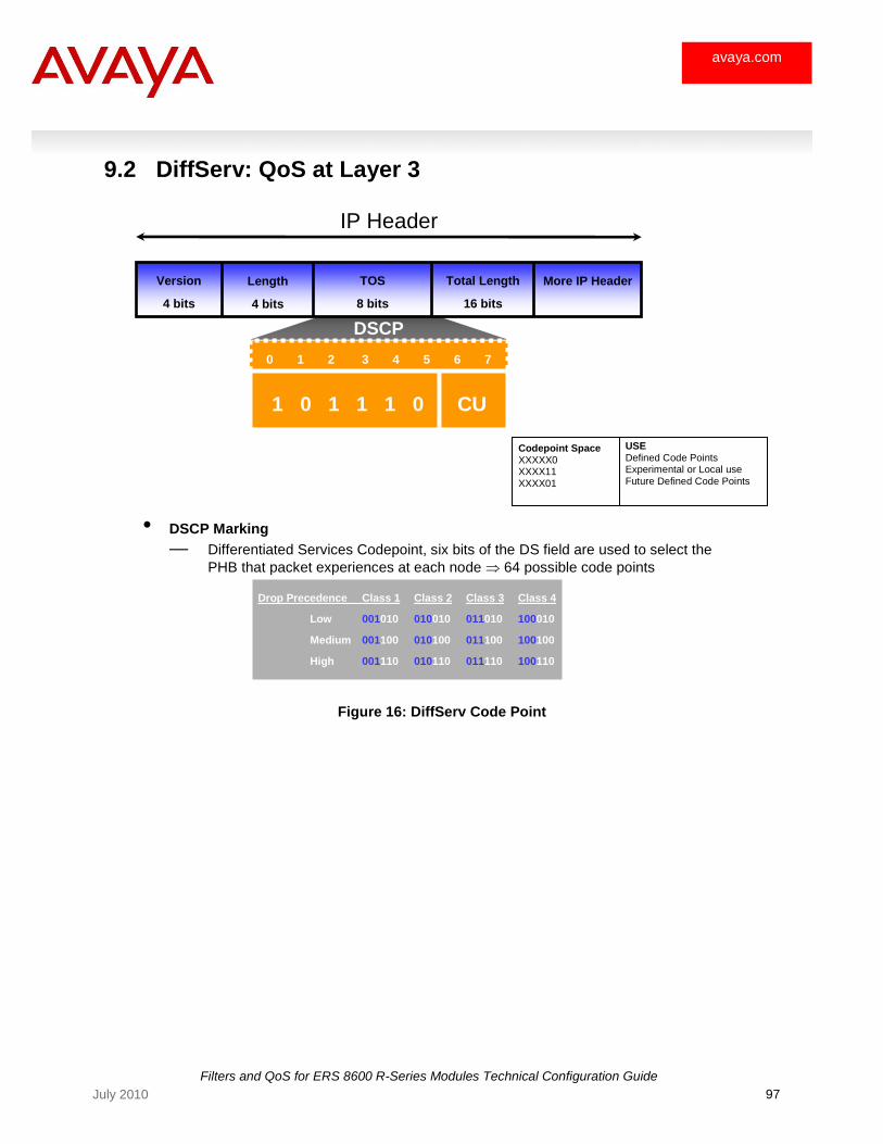
Filters and QoS for ERS 8600 R-Series Modules Technical Configuration Guide
97 July 2010
avaya.com
9.2 DiffServ: QoS at Layer 3
Figure 16: DiffServ Code Point
0 1 2 3 4 5 6 7
• DSCP Marking
— Differentiated Services Codepoint, six bits of the DS field are used to select the
PHB that packet experiences at each node 64 possible code points
Drop Precedence Class 1 Class 2 Class 3 Class 4
Low 001010 010010 011010 100010
Medium 001100 010100 011100 100100
High 001110 010110 011110 100110
1 0 1 1 1 0 CU
More IP Header
IP Header
Version
4 bits
Length
4 bits
TOS
8 bits
Total Length
16 bits
DSCP
Codepoint Space XXXXX0 XXXX11 XXXX01
USE Defined Code Points Experimental or Local use Future Defined Code Points
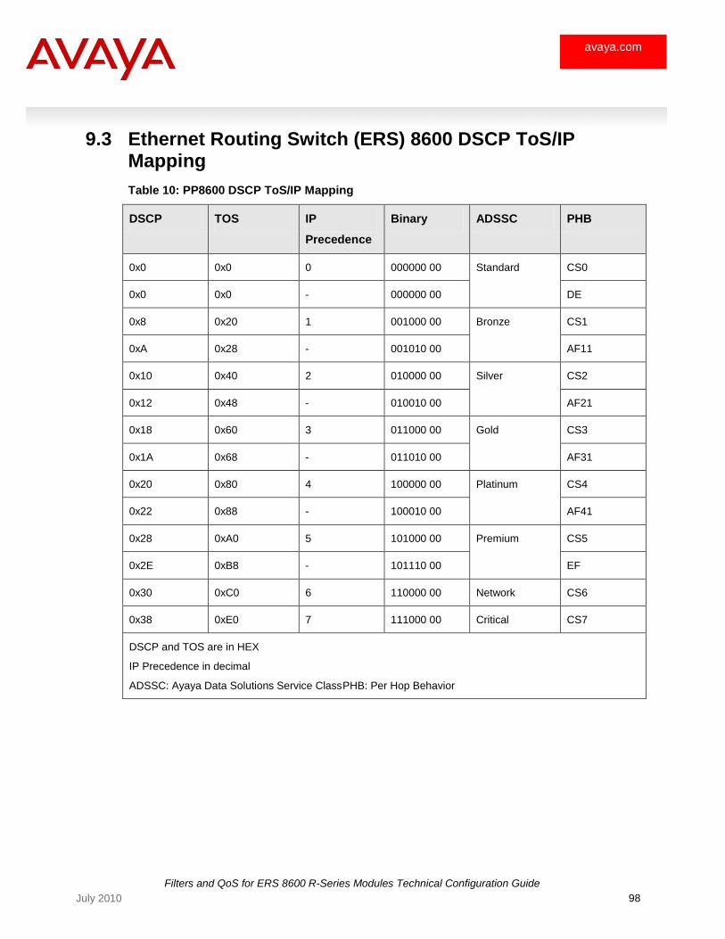
Filters and QoS for ERS 8600 R-Series Modules Technical Configuration Guide
98 July 2010
avaya.com
9.3 Ethernet Routing Switch (ERS) 8600 DSCP ToS/IP Mapping
Table 10: PP8600 DSCP ToS/IP Mapping
DSCP TOS IP
Precedence
Binary ADSSC PHB
0x0 0x0 0 000000 00 Standard CS0
0x0 0x0 - 000000 00 DE
0x8 0x20 1 001000 00 Bronze CS1
0xA 0x28 - 001010 00 AF11
0x10 0x40 2 010000 00 Silver CS2
0x12 0x48 - 010010 00 AF21
0x18 0x60 3 011000 00 Gold CS3
0x1A 0x68 - 011010 00 AF31
0x20 0x80 4 100000 00 Platinum CS4
0x22 0x88 - 100010 00 AF41
0x28 0xA0 5 101000 00 Premium CS5
0x2E 0xB8 - 101110 00 EF
0x30 0xC0 6 110000 00 Network CS6
0x38 0xE0 7 111000 00 Critical CS7
DSCP and TOS are in HEX
IP Precedence in decimal
ADSSC: Ayaya Data Solutions Service Class PHB: Per Hop Behavior

Filters and QoS for ERS 8600 R-Series Modules Technical Configuration Guide
99 July 2010
avaya.com
10. Appendix D – Hardware Overview
Redundant and load-sharing CPU/Switch Fabrics for up to 512 GIG of switching throughput (380Mpps)
Up to 3 CPUs per Control Plane
I/O blades with ingress and egress Route-Switch-Processors per 10GIG lane for line speed ingress/egress packet manipulation (filtering, bridging, routing, MPLS)
CLUE radix lookup table
FOQ for enhanced Queue management
Power PC 333 Mhz
256 Mb DRAM
System OPID
TAPMUX FSWIP
FFAD FFAD FFAD FFAD
Switch Fabric (SFF) Slot 5
Power PC 333 Mhz
SuperMezz Power PC 1GHz (optional)
256 Mb DRAM
256 Mb DRAM
Power PC 333 Mhz
256 Mb DRAM
System OPID
TAPMUX FSWIP
FFAD FFAD FFAD FFAD
Power PC 333 Mhz
256 Mb DRAM
256 Mb DRAM SuperMezz
Power PC 1GHz (optional)
Switch Fabric (SFF) Slot 6
FTAPMUX
INTERFACE PORT(S) 10x1GIG , 1x10GIG
I/0 Service Module
RSP
CLUE Lookup Table
RSP RS
P RSP RS
P RSP
INTERFACE PORT(S) 10x1GIG , 1x10GIG
INTERFACE
CO
Processor
FeedbackOutput Queuing
PIM IOM
10GIG 10GIG 10GIG
Full Duplex
10 GIG LANE
10GIG 10GIG
10GIG
RRSS
PP22..
55
RRSS
PP22..
55
RRSS
PP22..
55
RRSS
PP22..
55
RRSS
PP22..
55
RRSS
PP22..
55
F2E F2I F2E F2I F2E F2I
PORT(S) 10x1GIG , 1x10GIG
Filters and QoS for ERS 8600 R-Series Modules Technical Configuration Guide
100 July 2010
avaya.com
11. Software Baseline:
Software level of Ethernet Routing Switch (ERS) 8600 used for this document is based on release 4.0.
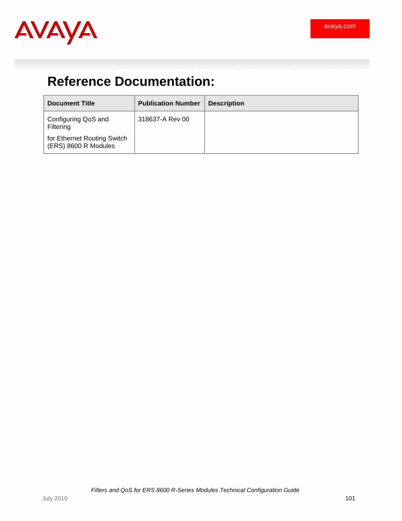
Filters and QoS for ERS 8600 R-Series Modules Technical Configuration Guide
101 July 2010
avaya.com
Reference Documentation:
Document Title Publication Number Description
Configuring QoS and Filtering
for Ethernet Routing Switch (ERS) 8600 R Modules
318637-A Rev 00
Filters and QoS for ERS 8600 R-Series Modules Technical Configuration Guide
102 July 2010
avaya.com
12. Customer service
Visit the Avaya Web site to access the complete range of services and support that Avaya provides. Go to www.avaya.com or go to one of the pages listed in the following sections.
12.1 Getting technical documentation
To download and print selected technical publications and release notes directly from the Internet, go to www.avaya.com/support.
12.2 Getting product training
Ongoing product training is available. For more information or to register, you can access the Web site at www.avaya.com/support. From this Web site, you can locate the Training contacts link on the left-hand navigation pane.
12.3 Getting help from a distributor or reseller
If you purchased a service contract for your Avaya product from a distributor or authorized reseller, contact the technical support staff for that distributor or reseller for assistance.
12.4 Getting technical support from the Avaya Web site
The easiest and most effective way to get technical support for Avaya products is from the Avaya Technical Support Web site at www.avaya.com/support.