Embed Size (px)
Citation preview

Film-TechThe information contained in this Adobe Acrobat pdffile is provided at your own risk and good judgment.
These manuals are designed to facilitate theexchange of information related to cinema
projection and film handling, with no warranties norobligations from the authors, for qualified field
service engineers.
If you are not a qualified technician, please make noadjustments to anything you may read about in these
Adobe manual downloads.
www.film-tech.com

TABLE OF CONTENTS
PREFACE 1
FIGURE 1 3
FIGURE 2 4
INSTALLATION
Unpacking 5
Mounting 5
Lamphouse Alignment 6
Lamphouse Light Shield 6
Picture Changeover 6
Lens Turret 6
Projection Lenses 7
START-UP PROCEDURES
Initial Oiling 8
Threading 9
Initial Operation 10
MAINTENANCE
Lubrication 11
Sprockets 11
Pad Rollers 11
Fastening Hardware 11
Film Gate 11
Film Trap 11
Lens Turret 12
Overall Appearance 12
FIGURE 3 13
FIGURE 4 14
FIGURE 5 15
FIGURE 6 16
i
TABLE OF CONTENTS (continued)
ADJUSTMENTS & REPLACEMENTS
Intermittent Shoe Replacement 17
Film Trap & Aperture Changer 17
Film Trap Lateral Rollers 17
Pressure Strap Replacement 18
Studio Guide Replacement 18
Aperture Plate Adjustment 18
Gear Compartment Cover 18
Intermittent Movement 18
Intermittent Sprocket 19
Oil Pump Feed Reversal 20
Framing Light 20
Film Sprocket Assemblies 20
Pad Roller Assemblies 20
Shutter Timing 21
Film Gate Replacement 21
Shutter Replacement 22
Automatic Lens Turret 22
SUPPLEMENTAL PARTS LISTS
Film Gate Assembly 24
Film Trap & Aperture Changer 26
Lens Turret 29
STRONG INTERNATIONALa division of Ballantyne of Omaha, Inc.
Engineering/SalesJune 1998
ii
PREFACE
THE SIMPLEX 35 PROJECTOR, Model PR2000, combining rugged construction with easeof operation, provides theatre owners with a superior mechanism, engineered to the high standards set for allStrong International products. The following design features illustrate why the Simplex 35 Projector isable to provide continuously excellent performance throughout its long operating life:
UNIT DESIGN
Unit method of design simplifies part replacement and maintenance. All units may be quicklyremoved and replaced. Components within a particular unit are just as easily handled.
SOUNDHEAD
Although the Simplex 35 Projector was designed for use with the Simplex 5 Star Soundhead, othersoundheads may be used without loss of quality.
MAIN DRIVE AND IDLER GEAR ASSEMBLIES
The main drive gear and idler assemblies are easily installed, insure proper driving from the soundhead,and are adjustable.
OPTICS
A conical shutter, positioned close to the picture aperture, provides very high light efficiency. Opticaldesign is compatible to modern xenon lamphouse systems.
LENS TURRET
The TU2020 Lens Turret is available in either Automatic (PR2000A) or Manual (PR2000M)configurations. The standard turret accommodates (1) each 2-25/32" Wide Screen (flat) and Anamorphic(CinemaScope) lens without use of a MagnaCom. A three-lens turret (TU2030) is available for the ModelPR2000. Individual focus controls permit concise focusing of each lens independently.
FILM COMPARTMENT
The roomy film compartment permits ease of threading and cleaning. The lens turret is hinged andswings open for added convenience.
GEAR COMPARTMENT
The gear compartment has a removable cover, rounded corners, and an enameled finish which simplifiescleaning.
1
MAIN FRAME
The main frame casting forms a single unit with the base, top, and front that is noteworthy for itssimplicity and strength.
FILM SPROCKETS
The upper feed and lower holdback sprockets, having twenty-four teeth each, reduce shaft speeds toprolong operating life, permit smoother wrap-around, and lessen the danger of splice breakage. Exclusive useof VKF® sprockets insures minimum film wear. The pad rollers are made of durable, lightweight nylon.
FILM TRAP
The film trap conforms to the curved film gate, and accommodates the multiple-aperture plate usedwith the TU2020 and TU2030. Film tension can be easily adjusted while the machine is running. The trapis readily removed and replaced for routine cleaning and maintenance.
FILM GATE
The curved gate, together with the film trap, controls the movement of the film past the aperture by fivedifferent tension settings. Gate curvature provides compensation for heat-induced warping of the film at theaperture, thus insuring a sharper image on the screen. Separate adjustment of the pivoting intermittent sprocketshoe pad minimizes picture �jump� with reduced gate tension for long print life. The film gate is easilyremoved, cleaned, and replaced.
INTERMITTENT MOVEMENT
The intermittent movement features a webbed starwheel for high strength, long life, and positiveregistration. The VKF® intermittent sprocket is adjustable, making absolute alignment possible.
LUBRICATION
A Spray-O-Matic Lubrication System, with a gear-driven oil pump, completely lubricates all movingcomponents. The moving parts inside the gear compartment are visible through the glass panel in the full-vision oil-sealed cover. The intermittent movement lubricates itself by pump action, and the Spray-O-Maticsystem. An oil level sight glass in the film compartment permits a visual check of the oil level.
COOLING
The Simplex 35 Projector includes a standard air-cooled trap, and a water-cooled trap is available as afactory option. Additional trap cooling, if required with high-wattage xenon lamphouses, may be implementedby means of the optional G-7903 Shutter Housing Blower Assembly.
VKF® is a registered trademark of LaVezzi Precision, Inc. Elmhurst, Illinois
2
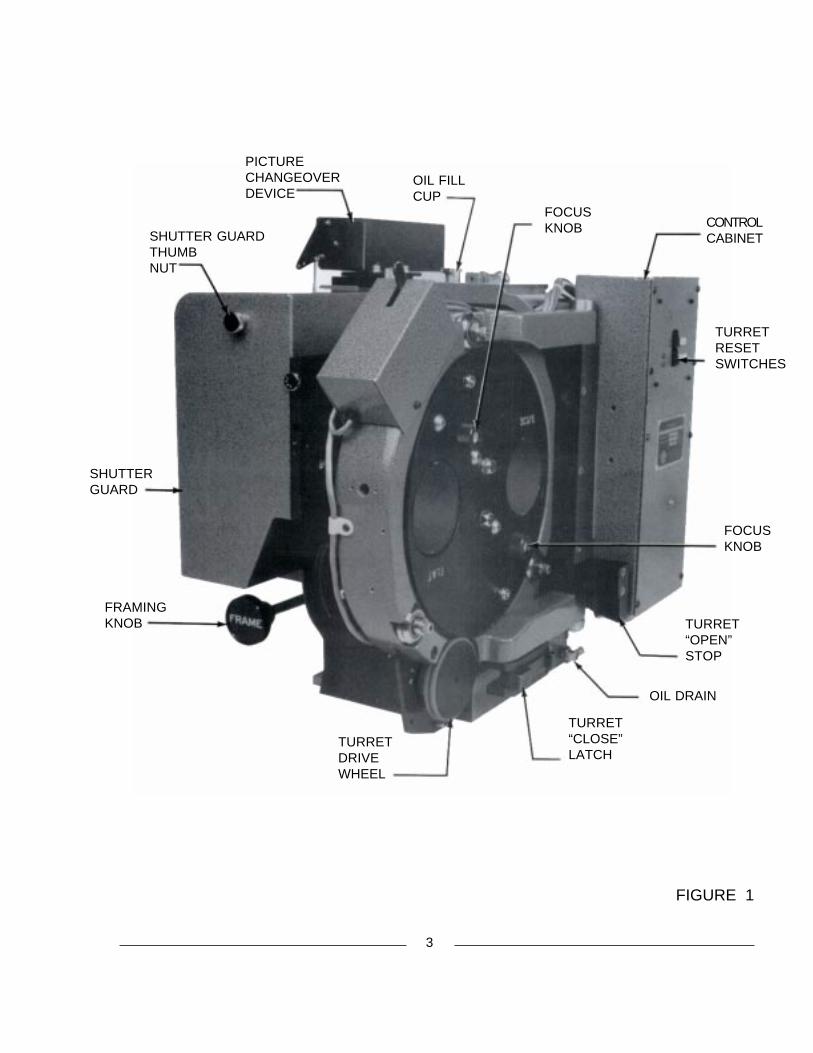
FIGURE 1
3
FOCUSKNOB
FOCUSKNOB
TURRET“OPEN”STOP
OIL DRAIN
TURRET“CLOSE”LATCH
TURRETDRIVEWHEEL
FRAMINGKNOB
SHUTTERGUARD
SHUTTER GUARDTHUMBNUT
PICTURECHANGEOVERDEVICE
OIL FILLCUP
CONTROLCABINET
TURRETRESETSWITCHES

FIGURE 2
4
SHUTTERADJUSTINGKNOB
UPPER FEEDSPROCKETASSEMBLY
APERTURE LOGICSENSOR SWITCH
RESET LEVER,INDEX STOPPIN
APERTURECUE
TURRET CATCH& DEADSTOP
HOLDBACKSPROCKETASSEMBLY
INTERMITTENTSPROCKET
FILM TENSIONADJUSTINGKNOB
GATERELEASEPIN
INSTALLATION
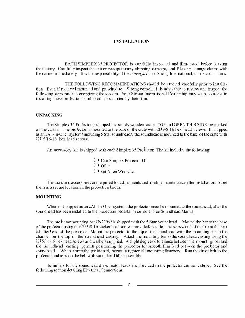
EACH SIMPLEX 35 PROJECTOR is carefully inspected and film-tested before leavingthe factory. Carefully inspect the unit on receipt for any shipping damage, and file any damage claims withthe carrier immediately. It is the responsibility of the consignee, not Strong International, to file such claims.
THE FOLLOWING RECOMMENDATIONS should be studied carefully prior to installa-tion. Even if received mounted and prewired to a Strong console, it is advisable to review and inspect thefollowing steps prior to energizing the system. Your Strong International Dealership may wish to assist ininstalling those projection booth products supplied by their firm.
UNPACKING
The Simplex 35 Projector is shipped in a sturdy wooden crate. TOP and OPEN THIS SIDE are markedon the carton. The projector is mounted to the base of the crate with (2) 3/8-16 hex head screws. If shippedas an �All-In-One� system (including 5 Star soundhead), the soundhead is mounted to the base of the crate with(2) 5/16-18 hex head screws.
An accessory kit is shipped with each Simplex 35 Projector. The kit includes the following:
(1) Can Simplex Projector Oil(1) Oiler(1) Set Allen Wrenches
The tools and accessories are required for adjustments and routine maintenance after installation. Storethem in a secure location in the projection booth.
MOUNTING
When not shipped as an �All-In-One� system, the projector must be mounted to the soundhead, after thesoundhead has been installed to the projection pedestal or console. See Soundhead Manual.
The projector mounting bar (P-2396) is shipped with the 5 Star Soundhead. Mount the bar to the baseof the projector using the (2) 3/8-16 socket head screws provided; position the slotted end of the bar at the rear(shutter) end of the projector. Mount the projector to the top of the soundhead with the mounting bar in thechannel on the top of the soundhead casting. Attach the mounting bar to the soundhead casting using the(2) 5/16-18 hex head screws and washers supplied. A slight degree of tolerance between the mounting bar andthe soundhead casting permits positioning the projector for smooth film feed between the projector andsoundhead. When correctly positioned, securely tighten all mounting fasteners. Run the drive belt to theprojector and tension the belt with soundhead idler assembly.
Terminals for the soundhead drive motor leads are provided in the projector control cabinet. See thefollowing section detailing Electrical Connections.
5
LAMPHOUSE OPTICAL ALIGNMENT
Carefully follow the lamphouse manufacturer�s instructions regarding correct optical alignmentbetween the lamphouse and projector. The lamphouse is generally aligned to the projector aperture, butsome consoles require positioning the projector and soundhead to the optical center of the lamphouse. DO NOTalter the film path between the projector and soundhead in the course of these adjustments. Never operatethe lamphouse with the douser open unless the projector is running.
LAMPHOUSE LIGHT SHIELD
Light shields, or nose cones, supplied by the lamphouse manufacturer, may be installed between theprojector shutter guard and the lamphouse snood. Make certain that the nose cone does not obstruct the rotationof the shutter. Trim or otherwise modify the nose cone as required.
ELECTRICAL CONNECTIONS
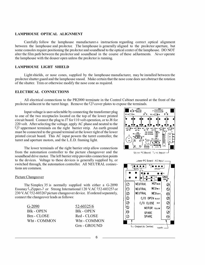
All electrical connections to the PR2000 terminate in the Control Cabinet mounted at the front of theprojector adjacent to the turret hinge. Remove the (2) cover plates to expose the terminals.
Input voltage is user-selectable by connecting the transformer plugto one of the two receptacles located on the top of the lower printedcircuit board. Connect the plug to J7 for 110 volt operation, or to J8 for220 volt. After selecting the voltage, apply AC phase and neutral to the(2) uppermost terminals on the right barrier strip. An earth groundmust be connected to the ground terminal at the lower right of the lowerprinted circuit board. This AC input powers the turret controller, theturret and aperture motors, and the L.E.D. framing light.
The lower terminals of the right barrier strip allow connectionsfrom the automation controller to the picture changeover and thesoundhead drive motor. The left barrier strip provides connection pointsto the devices. Voltage to these devices is generally supplied by, orswitched through, the automation controller. All NEUTRAL connec-tions are common.
Picture Changeover
The Simplex 35 is normally supplied with either a G-2090Essanay (�Zipper�) or Strong International 120 V.AC (52-60325) or230 V.AC (52-60326) picture changeover device. If ordered separately,connect the changeover leads as follows:
G-2090 52-60325/6Blk - OPEN Blk - OPENBrn - CLOSE Red - CLOSEWht - COMMON Wht - COMMON
Grn - GROUND
6
NOTE: These changeover devices require an AC pulse to operate. Connecting thechangeover device to a sustained AC circuit will destroy the electrical coil(s). Checkcarefully the instructions supplied with the automation controller and/or the (installer-supplied) switching circuit.
Lens Turret
The MANUAL lens turret requires no electrical connections. Installer connections to the AUTO-MATIC turret are made to the J4 terminals located on the upper printed circuit board in the control box adjacentto the turret on the front of the projector. The inputs (FEED, SPECIAL, FLAT, and SCOPE) are derivedfrom an automation controller and/or other installer-supplied circuitry. NOTE: “SPECIAL” input appliesonly to a third lens in a three-lens turret.
LENS INSTALLATION
The lens barrels are individually marked to designate their screen format. The barrels of the standardtwo-lens turret are marked SCOPE (CinemaScope, or anamorphic) and FLAT (�wide screen,� or non-anamorphic). Lens barrels on the three-lens turret are marked SC (CinemaScope), FL (Flat), and SP (Special).The lenses must be installed in their designated barrels for correct aperture logic. Magnacom lenses are notrequired in any configuration.
Rotate the turret to the SCOPE position. The automatic turret will index to this position after the SCOPEswitch is pressed; the manual turret must be indexed by hand. Make certain the SCOPE aperture plate is inposition. Center the focus adjustment screw, allowing equal travel forward and back. Insert the CinemaScopelens and anamorphic adapter into the SCOPE barrel. Start the projector, ignite the lamphouse, and projecta picture to the screen. Move the lens inside the barrel until a sharply focused picture is projected, and theanamorphic correction is on the correct horizontal plane. Securely tighten the lens locking knob on the top ofthe SCOPE barrel. Close the lamphouse douser.
Reset the turret to FLAT format, and make certain the FLAT aperture is in position. Center the focusadjustment screw, and insert the FLAT lens. Open the lamphouse douser and move the lens inside the barreluntil a sharply focused picture is projected. Tighten the lens locking knob above the FLAT barrel.
Repeat the above procedures as required for the �special� lens used in a three-lens turret. Onceinstalled, DO NOT remove the lenses for cleaning. The turret is hinged, and opens to permit cleaning the rearsurfaces of the lenses.
File the aperture plates to size the picture to the screen and/or masking. NOTE: When projecting awhite light while filing apertures, close the lamphouse douser frequently to allow the lens to cool.
DO NOT attempt to correct �keystoning� by shimming the turret or offsetting the position of the lenses.The lenses must be positioned on optical center to project a satisfactory image.
7
START-UP PROCEDURES
ALL SIMPLEX PROJECTORS are carefully �run-in� at the factory before shipping. No�run-in� period at the installation site is required. Some gear whine may be noticed initially, but shoulddisappear after a few hours of operation.
INITIAL OILING
One quart of Simplex Projector Oil is included in the accessory kit supplied with new equipment. USEONLY GENUINE SIMPLEX PROJECTOR OIL IN THE MECHANISM. Use of other lubricants mayinhibit oil pump operation and damage moving parts. Additional oil is available through authorized StrongInternational Dealers; order Simplex Part No. R-0059 for (1) quart quantities.
DO NOT, at any time, operate the projector without oil.
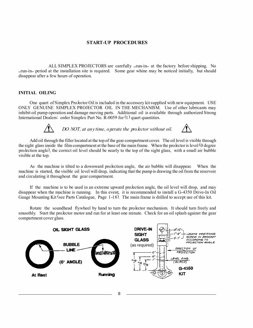
Add oil through the filler located at the top of the gear compartment cover. The oil level is visible throughthe sight glass inside the film compartment at the base of the main frame. When the projector is level (0 degreeprojection angle), the correct oil level should be nearly to the top of the sight glass, with a small air bubblevisible at the top.
As the machine is tilted to a downward projection angle, the air bubble will disappear. When themachine is started, the visible oil level will drop, indicating that the pump is drawing the oil from the reservoirand circulating it throughout the gear compartment.
If the machine is to be used in an extreme upward projection angle, the oil level will drop, and maydisappear when the machine is running. In this event, it is recommended to install a G-4350 Drive-In OilGauge Mounting Kit (see Parts Catalogue, Page 1-18). The main frame is drilled to accept use of this kit.
Rotate the soundhead flywheel by hand to turn the projector mechanism. It should turn freely andsmoothly. Start the projector motor and run for at least one minute. Check for an oil splash against the gearcompartment cover glass.
(as required)
8
THREADING
Threading the projector correctly is one of the operator�s most important duties. Careful attentionduring this operation pays off in improved performances and long print life.
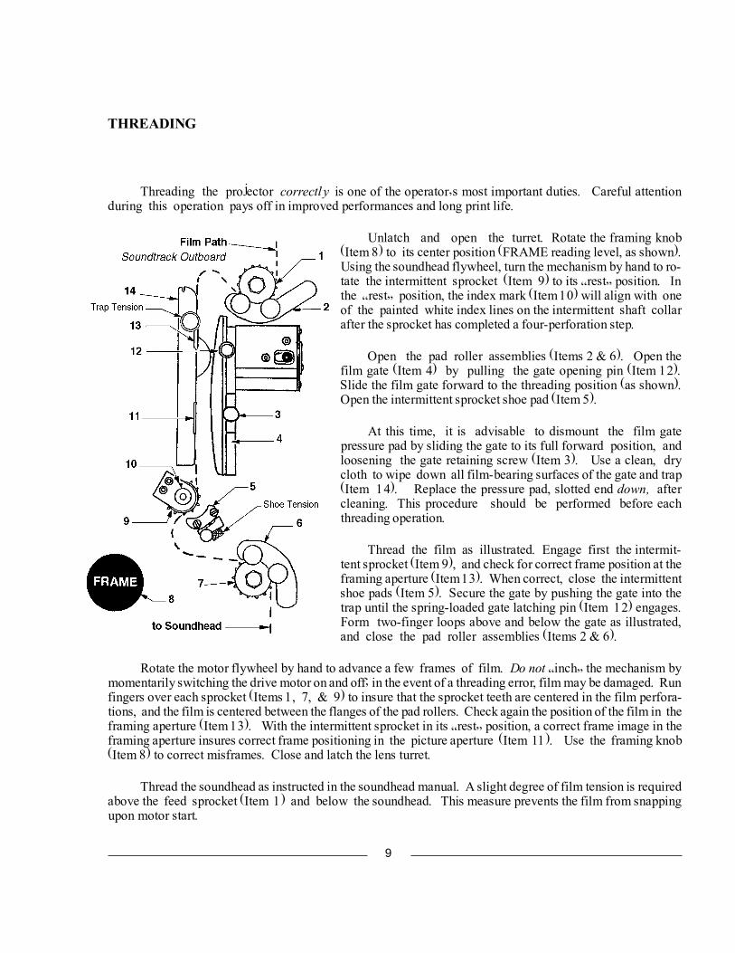
Unlatch and open the turret. Rotate the framing knob(Item 8) to its center position (FRAME reading level, as shown).Using the soundhead flywheel, turn the mechanism by hand to ro-tate the intermittent sprocket (Item 9) to its �rest� position. Inthe �rest� position, the index mark (Item 10) will align with oneof the painted white index lines on the intermittent shaft collarafter the sprocket has completed a four-perforation step.
Open the pad roller assemblies (Items 2 & 6). Open thefilm gate (Item 4) by pulling the gate opening pin (Item 12).Slide the film gate forward to the threading position (as shown).Open the intermittent sprocket shoe pad (Item 5).
At this time, it is advisable to dismount the film gatepressure pad by sliding the gate to its full forward position, andloosening the gate retaining screw (Item 3). Use a clean, drycloth to wipe down all film-bearing surfaces of the gate and trap(Item 14). Replace the pressure pad, slotted end down, aftercleaning. This procedure should be performed before eachthreading operation.
Thread the film as illustrated. Engage first the intermit-tent sprocket (Item 9), and check for correct frame position at theframing aperture (Item 13). When correct, close the intermittentshoe pads (Item 5). Secure the gate by pushing the gate into thetrap until the spring-loaded gate latching pin (Item 12) engages.Form two-finger loops above and below the gate as illustrated,and close the pad roller assemblies (Items 2 & 6).
Rotate the motor flywheel by hand to advance a few frames of film. Do not �inch� the mechanism bymomentarily switching the drive motor on and off; in the event of a threading error, film may be damaged. Runfingers over each sprocket (Items 1, 7, & 9) to insure that the sprocket teeth are centered in the film perfora-tions, and the film is centered between the flanges of the pad rollers. Check again the position of the film in theframing aperture (Item 13). With the intermittent sprocket in its �rest� position, a correct frame image in theframing aperture insures correct frame positioning in the picture aperture (Item 11). Use the framing knob(Item 8) to correct misframes. Close and latch the lens turret.
Thread the soundhead as instructed in the soundhead manual. A slight degree of film tension is requiredabove the feed sprocket (Item 1) and below the soundhead. This measure prevents the film from snappingupon motor start.
9
INITIAL OPERATION
CLEAN ALL FILM BEARING SURFACES BEFORE EACH THREADING OPERATION. Checkall sprocket teeth for hooks or burrs; replace if required. Keep all pad rollers clean and operating freely.Make certain the turret is set to the correct lens and aperture for the desired screen format. FLAT format isgenerally used for initial setup of the projection system.
The Film Trap Tension Knob is located at the top of the film trap, and is graduated in Steps 1 - 5. Rotatethis knob counterclockwise to its stop. This setting (�1�) indicates minimum trap tension. Thread film intothe projector, ignite the lamp, and project a picture to the screen. Use of RP-40 test film is highly desirable forthis stage of machine set-up. This test film may be purchased directly from the Society of Motion Pictureand Television Engineers:
SMPTE Test Film Department595 West Hartsdale AvenueWhite Plains, New York 10607
Order: 35 PA-50 (50 ft.) or 35 PA-200 (200 ft.)
Install the lenses and set focus as detailed in the preceding INSTALLATION section. File the aperturesto fit screen parameters.
If the projected picture is unsteady, rotate the film trap tension knob clockwise one step at a time, whilethe film is running. Tighten the knurled knob on the intermittent shoe assembly gradually to remove picture�jump.� Always adjust for the minimum tension required to project a steady picture. Excessive tension notonly increases wear on parts, but in extreme cases may cause torn perforations and film breakage.
Check the projected picture for travel ghost. �Travel Ghost� is the term commonly applied to verticalstreaking of lighter areas against a darker area, and is particularly noticeable during opening or closing titlesand credits. If ghosting is apparent, rotate the shutter adjustment knob on the top of the projector until theghosting disappears. If the ghost cannot be eliminated by means of this knob, see �Shutter Timing� in theADJUSTMENTS AND REPLACEMENTS section of this manual.
The rotation travel of the lens turret is limited by the indexing stop pin mounted to the outer ring of theturret. The automated turret on the PR2000 includes a solenoid which pulls the pin when the turret is inmotion. Two coil expansion springs seat the pin when the turret is at rest. When first energized, theautoturret will automatically index to FLAT mode, if not already in FLAT. The proximity switch on the turretring will sense the cueing magnet mounted to the index stop bracket and set the correct aperture (one magnetmounted inboard = FLAT, one magnet mounted outboard = SCOPE, two magnets = SPECIAL).
In the event of a turret motor failure, the automatic turret can be operated manually until a replacementmotor is obtained. It is advisable to de-energize the turret control until the replacement motor is installed. Thedual aperture plate can be pushed in or pulled out manually to set the correct format.
10
MAINTENANCE
THE PROJECTOR MECHANISM should periodically undergo a careful and thoroughinspection. A regular schedule of adjustments and replacement of wearing parts will insure long life andminimize downtime.
LUBRICATION
Drain and discard the projector oil at least annually. Clean the oil pump intake filter and the oil reservoir.Replace with genuine Simplex Projector Oil (Part No. R-0059).
SPROCKETS
Clean sprocket teeth daily with a typewriter brush or used toothbrush (with softened bristles). Examineeach sprocket carefully for wear, undercutting (�hooks�), and/or looseness. Replace as required. Assum-ing the projector is used for forward-running only, hooked sprockets can be re-used by reversing the sprocket onits shaft. Check the alignment of the intermittent sprocket.
PAD ROLLERS
Check pad rollers for grooves, flat spots, and/or looseness. Check rollers thoroughly to relieve binding;replace as required. Inspect alignment of pad rollers to sprockets; centered, flanges not rubbing, spaced (2) filmthicknesses above sprocket face.
FASTENING HARDWARE
Check all fasteners for tightness. Normal operating vibration over prolonged periods may cause fastenersto loosen. Tighten as required.
FILM GATE
Remove all foreign matter (dirt, wax) by cleaning thoroughly. Examine film runners and intermittentshoes for wear; replace if required. Check alignment of intermittent shoes to intermittent sprocket faces.Check gate opening and closing slide for smooth operation; clean linear bearing to relieve binding. The gatemount is adjustable by means of slotted mounting holes; check periodically to insure secure gate closure.
FILM TRAP
Examine lateral guide rollers for grooves and binding. Clean carefully, adjust, or replace. Remove allforeign material from tension straps. Inspect for wear; replace if required.
To remove the trap from the main frame, cycle the aperture plate to FLAT. Loosen the wing-head,quarter-turn screw and raise the hinged portion of the aperture plate drive. Lifting the hinged plate will exposethe slotted head of the trap mounting screw, and allow access for a flat-bladed screwdriver.
11
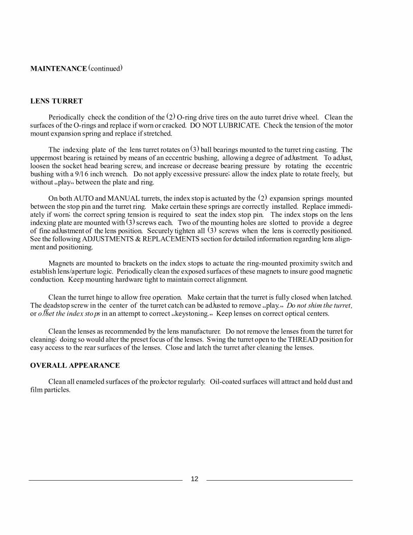
MAINTENANCE (continued)
LENS TURRET
Periodically check the condition of the (2) O-ring drive tires on the auto turret drive wheel. Clean thesurfaces of the O-rings and replace if worn or cracked. DO NOT LUBRICATE. Check the tension of the motormount expansion spring and replace if stretched.
The indexing plate of the lens turret rotates on (3) ball bearings mounted to the turret ring casting. Theuppermost bearing is retained by means of an eccentric bushing, allowing a degree of adjustment. To adjust,loosen the socket head bearing screw, and increase or decrease bearing pressure by rotating the eccentricbushing with a 9/16 inch wrench. Do not apply excessive pressure; allow the index plate to rotate freely, butwithout �play� between the plate and ring.
On both AUTO and MANUAL turrets, the index stop is actuated by the (2) expansion springs mountedbetween the stop pin and the turret ring. Make certain these springs are correctly installed. Replace immedi-ately if worn; the correct spring tension is required to seat the index stop pin. The index stops on the lensindexing plate are mounted with (3) screws each. Two of the mounting holes are slotted to provide a degreeof fine adjustment of the lens position. Securely tighten all (3) screws when the lens is correctly positioned.See the following ADJUSTMENTS & REPLACEMENTS section for detailed information regarding lens align-ment and positioning.
Magnets are mounted to brackets on the index stops to actuate the ring-mounted proximity switch andestablish lens/aperture logic. Periodically clean the exposed surfaces of these magnets to insure good magneticconduction. Keep mounting hardware tight to maintain correct alignment.
Clean the turret hinge to allow free operation. Make certain that the turret is fully closed when latched.The deadstop screw in the center of the turret catch can be adjusted to remove �play.� Do not shim the turret,or offset the index stops in an attempt to correct �keystoning.� Keep lenses on correct optical centers.
Clean the lenses as recommended by the lens manufacturer. Do not remove the lenses from the turret forcleaning; doing so would alter the preset focus of the lenses. Swing the turret open to the THREAD position foreasy access to the rear surfaces of the lenses. Close and latch the turret after cleaning the lenses.
OVERALL APPEARANCE
Clean all enameled surfaces of the projector regularly. Oil-coated surfaces will attract and hold dust andfilm particles.
12
13
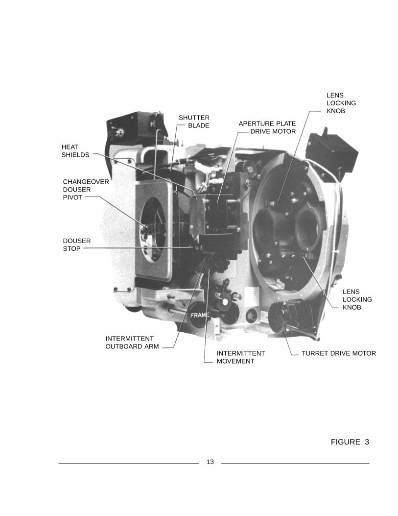
FIGURE 3
HEATSHIELDS
SHUTTER BLADE APERTURE PLATE
DRIVE MOTOR
LENSLOCKINGKNOB
LENSLOCKINGKNOB
TURRET DRIVE MOTORINTERMITTENTMOVEMENT
INTERMITTENTOUTBOARD ARM
DOUSERSTOP
CHANGEOVERDOUSERPIVOT
14
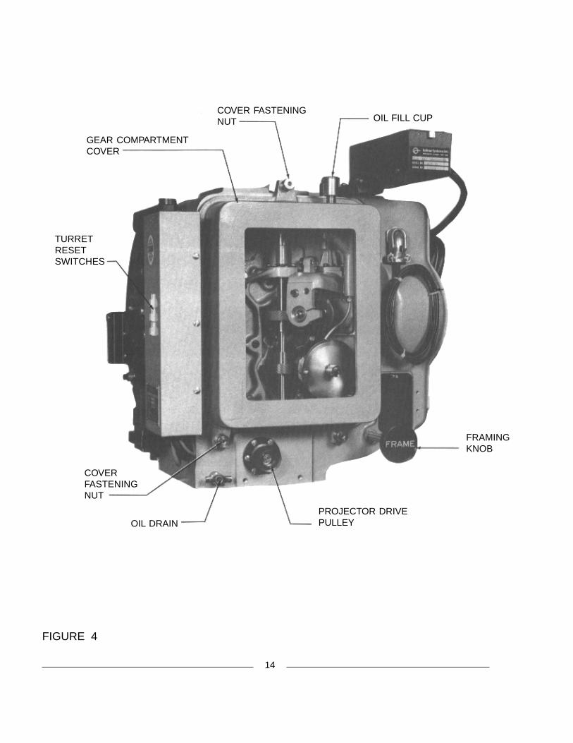
FIGURE 4
FRAMINGKNOB
PROJECTOR DRIVEPULLEYOIL DRAIN
COVERFASTENINGNUT
TURRETRESETSWITCHES
GEAR COMPARTMENTCOVER
COVER FASTENINGNUT OIL FILL CUP
15
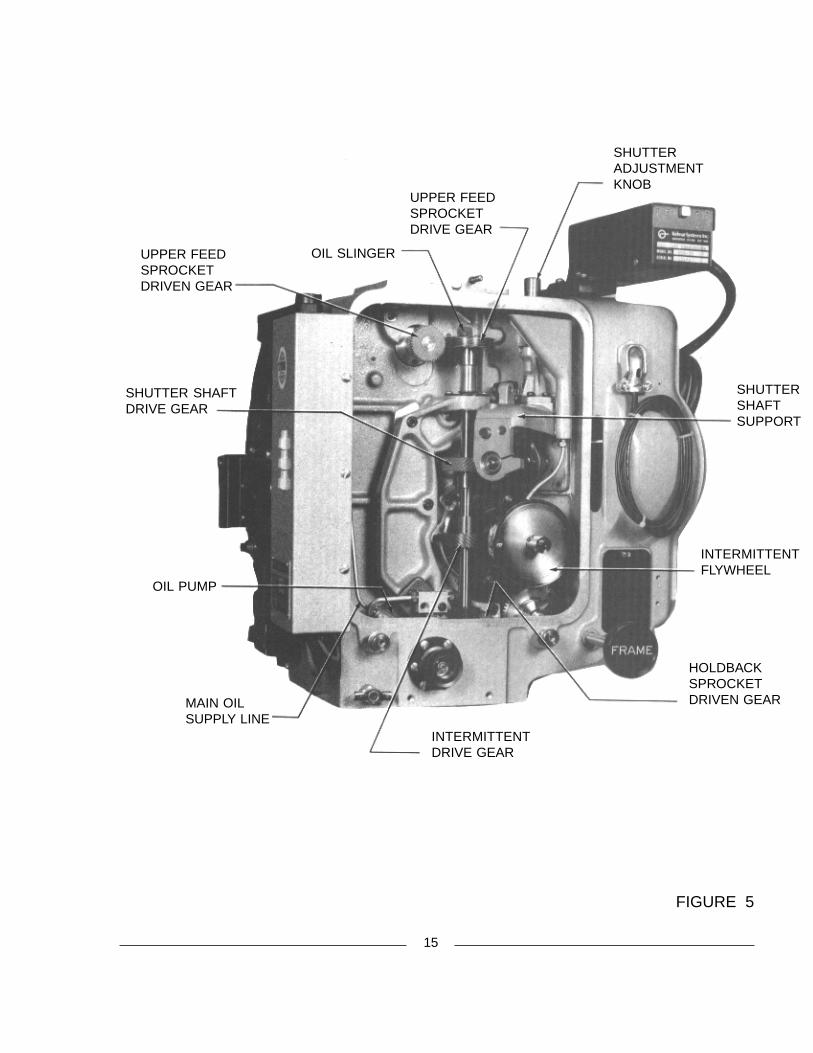
FIGURE 5
SHUTTER SHAFTDRIVE GEAR
UPPER FEEDSPROCKETDRIVEN GEAR
OIL SLINGER
UPPER FEEDSPROCKETDRIVE GEAR
SHUTTERADJUSTMENTKNOB
SHUTTERSHAFTSUPPORT
INTERMITTENTFLYWHEEL
HOLDBACKSPROCKETDRIVEN GEAR
INTERMITTENTDRIVE GEAR
MAIN OILSUPPLY LINE
OIL PUMP
16
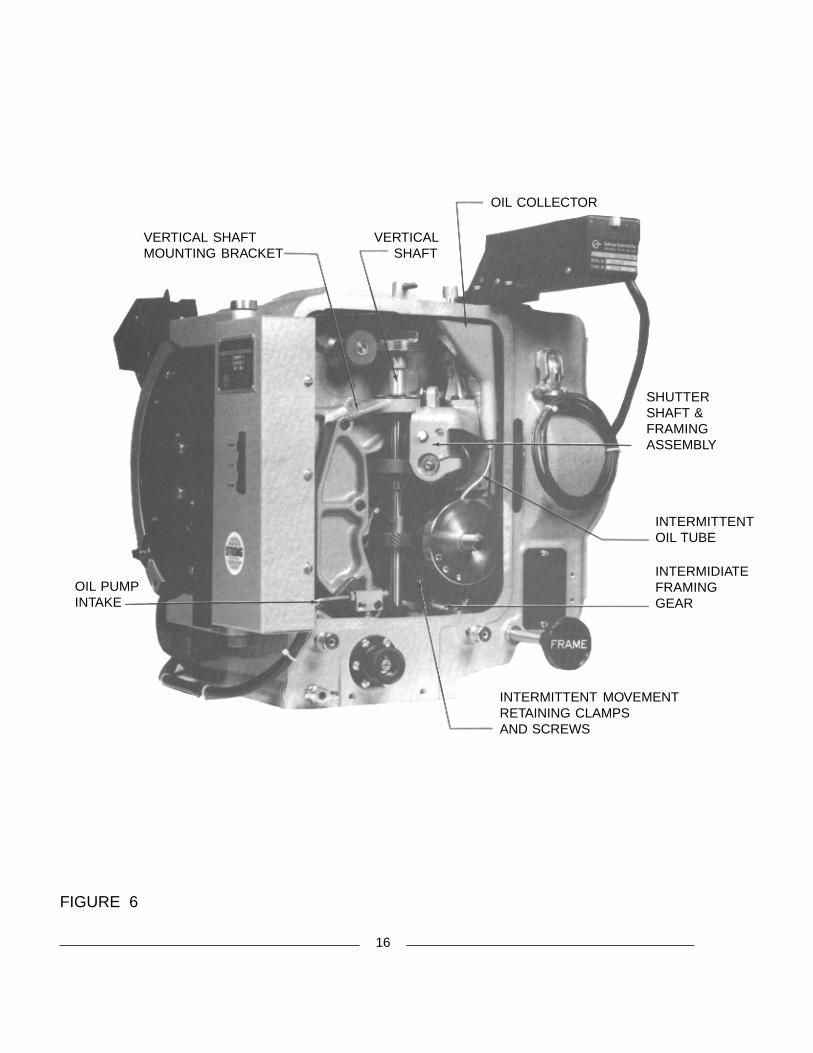
FIGURE 6
OIL COLLECTOR
VERTICAL SHAFT
VERTICAL SHAFTMOUNTING BRACKET
OIL PUMPINTAKE
INTERMITTENT MOVEMENTRETAINING CLAMPSAND SCREWS
INTERMIDIATEFRAMINGGEAR
SHUTTERSHAFT &FRAMINGASSEMBLY
INTERMITTENTOIL TUBE
ADJUSTMENTS AND REPLACEMENTS
REFER TO THIS SECTION in conjunction to performing the steps in the MAINTENANCEsection. Conscientious maintenance and service of the Simplex 35 Projector Mechanism will insure manyyears of excellent performance.
ADJUSTMENTS are quickly accomplished, and replacements performed, as all units andcomponents are readily removed. Adjustments and replacements described below may be performed byqualified projection booth personnel. Any elements of maintenance and service not detailed below should bereferred to an authorized Strong International Dealer.
INTERMITTENT SHOE REPLACEMENT
Open lens turret. Dismount the shoe pad assembly by removing the (2) keeper screws, stud, and coilspring. Replace worn components in matched pairs as required. Reassemble and remount.
FILM TRAP AND APERTURE CHANGER ASSEMBLY
Dismount the film gate and the shutter guard. To remove the trap from the main frame, cycle the apertureplate to FLAT. Loosen the wing-head, quarter-turn screw and raise the hinged portion of the aperture platedrive. Lifting the hinged plate will expose the slotted head of the trap mounting screw, and allow access for acommon flat-bladed screwdriver. Loosen the captive mounting screw, unplug the aperture motor and framinglight connectors, and remove the trap assembly from the film compartment.
To replace, make certain that the contacting surfaces on both the mounting plate and the trap casting areclean. Slide the film trap in so that it registers with the (2) dowel pins on the mounting plate. Securely tightenthe captive screw. Plug in the aperture change motor and framing light. Lower the hinged plate over theaperture plate and secure using the quarter-turn fastener.
Check the alignment of the intermittent sprocket to the film trap (see INTERMITTENT MOVEMENTsection following).
FILM TRAP LATERAL GUIDE ROLLERS
Dismount the film trap and associated components (see above). The (2) bearing blocks retaining thelateral guide rollers are slotted to permit adjusting the position of the rollers on the horizontal plane. Loosen the(2) socket head mounting screws and position the lateral guide rollers to center the film at the picture aperture.Allow adequate end play to permit free movement of the ball bearings. Check the bearings for proper rotation;lubricate as required using a minimum amount of sewing machine oil from an injection applicator. Wipe offexcess oil.
Once the lateral guide roller position is correctly set, the position may be fixed by setting the brass stopplate (see Item 62 on the FILM TRAP Parts Drawing in Supplemental Parts List) to rest against the outboardbearing bracket (Item 12). After setting the stop plate, the lateral guide rollers can be removed, cleaned, andreplaced, and the correctly centered position will be maintained.
17
PRESSURE STRAP REPLACEMENT
Dismount the film trap and associated components. Rotate the trap tension knob fully counterclockwiseto position �1.� Remove the (2) screws from each strap, and remove the straps. Replace with new straps andreassemble. NOTE: Project film to reset gate pressure (see START-UP PROCEDURES).
STUDIO GUIDE REPLACEMENT
Remove the film gate and open the turret assembly. Remove the (2) socket head screws and washers,and dismount the studio guide. Position and install the replacement studio guide; close the turret and replacethe film gate.
APERTURE PLATE ADJUSTMENT
Gear mesh between the drive motor spur gear and the rack gear on the aperture slide can be set byloosening the (2) 10-32 socket head screws and moving the motor, on its mounting plate, up or down. The motorplate mounting holes are slotted for this purpose.
Horizontal travel of the aperture plate is also adjustable. The inboard stop is set by loosening the sockethead screw inside the eccentric bushing adjacent to the aperture slide and rotating the bushing to the desired stoppoint. The outboard stop is fixed by positioning a set screw in the housing plate immediately below the aperturedrive slide rod.
GEAR COMPARTMENT COVER REMOVAL
Remove the gear compartment cover only when absolutely necessary, and only after the machine hasbeen at rest for at least (10) minutes to allow all oil to settle into the reservoir. Remove the (3) cover fasteningthumb nuts. Make certain no foreign material deposits in the gear compartment while the cover is removed.Before replacing the cover, wipe all oil from the cover gasket and the mating surface on the projector mainframe. Any oil remaining on these surfaces will provide an oil seepage path after the cover is replaced. Tightenall (3) thumb nuts equally and fingertight, just enough to form an oil-tight seal.
INTERMITTENT MOVEMENT REPLACEMENT
1. Open the film gate. Rotate the framing knob (on the gear side) fully counterclockwise.2. Set the shutter adjusting knob in mid-position. To locate mid-position, rotate the knob to its stop, and
reverse 1½ turns.3. Remove the gear compartment cover (see above).4. Rotate the vertical shaft until the intermittent drive gear mounting screw is visible. Remove the mounting
screw and slide the gear downward.5. Loosen the (2) intermittent retaining clamp screws on the framing cam and position the clamps to clear the
intermittent case.6. Withdraw the intermittent assembly from the gear compartment side, taking care not to strike the inter-
mittent oil feed tube positioned above the intermittent assembly.7. Slide the replacement intermittent movement into position. The keyway in the intermittent case is aligned
with the key in the framing cam.
18
INTERMITTENT MOVEMENT REPLACEMENT (continued)
8. Rotate the intermittent retaining clamps to retain the intermittent assembly and tighten the fasteningscrews securely.
9. Rotate the shutter counterclockwise (from the rear of projector) until its leading edge is exactly in linewith the upper edge of the picture aperture (aperture just completely blocked).
10. Rotate intermittent flywheel until the intermittent sprocket turns clockwise; (1) of the (4) index lines onthe outboard collar will align with the index line on the outboard bearing support arm.
11. Continue to rotate the flywheel in the same direction until the intermittent sprocket just begins to move.12. Reverse rotation of the flywheel until the sprocket stops. Then, rotate the flywheel counterclockwise
until the start of sprocket rotation is felt.13. Continue to rotate the flywheel until the precise point at which the sprocket is about to move is reached.
Retain that setting.14. Raise the intermittent drive gear and rotate it tooth by tooth until it meshes with the intermittent driven
gear. At this time, the mounting hole in the drive gear should align with the hole in the vertical shaft. Donot rotate the vertical shaft or driven gear. Replace the gear mounting screw.
15. Align the intermittent sprocket with the film trap (see below).
INTERMITTENT SPROCKET ALIGNMENT
Loosen the intermittent sprocket fastening screw and slide the sprocket, as required, until the outside faceof the sprocket is flush with a straight edge (i.e. machinist�s ruler) placed on the outside face of the lowerholdback sprocket. Securely tighten the intermittent sprocket fastening screw. Thread a length of scrap filmbetween the upper sprocket and the intermittent sprocket; set lateral guide rollers and studio guide as required.
INTERMITTENT SPROCKET REPLACEMENT
1. Remove film gate. Dismount shutter guard and film trap.2. Rotate the framing knob to its extreme clockwise position to expose the intermittent sprocket film stripper
mounting screw. Remove the screw and stripper.3. Turn the projector mechanism by hand so that one of the collar index lines aligns with the index mark on
the outboard arm, and the sprocket mounting screw is exposed.4. Remove the intermittent sprocket mounting screw and nut.5. Loosen the (2) intermittent outboard collar set screws and remove the collar.6. Remove the (2) outboard arm socket head mounting screws and dismount the outboard arm.7. Remove the worn intermittent sprocket. Slide the replacement sprocket onto shaft.8. Position the intermittent outboard bearing arm on intermittent sprocket and start the (2) socket head mounting
screws finger tight. Adjust the bearing arm, as required, so that the bearing is precisely centered withrespect to the intermittent shaft. Tighten the (2) mounting screws.
9. Fasten the replacement intermittent sprocket to the intermittent shaft using the screw and nut supplied.10. Slide the intermittent outboard collar on the intermittent shaft and align one of its index lines to the index
mark on the outboard bearing arm. Pull the intermittent sprocket OUT while pressing the outboard collarIN, so that shaft end play is just perceptible.
11. Securely tighten the (2) collar set screws. Check that the shaft end play is just perceptible.12. Replace intermittent sprocket film stripper.13. Align the intermittent sprocket (see above).14. Replace film trap and shutter guard. Install the film gate.
19
OIL PUMP FEED REVERSAL (Drive-In Theatre Operation; Upward Projection Angle)
See PARTS CATALOGUE, Page 1-20. Remove gear compartment cover. Remove compression nut,compression bushing, and oil line and filter from the left-hand side of the oil tube connector. Reconnect partsin sequence on the right-hand side, and tighten. Install the Drive-In Oil Gauge Assembly (G-4350) if desired(see PARTS CATALOGUE, Page 1-18).
FRAMING LIGHT REPLACEMENT
Remove shutter guard. Unplug and dismount L.E.D. Printed Circuit Board assembly from back offraming aperture; replace with new unit. Connect to wire harness; replace shutter guard.
FEED AND HOLDBACK SPROCKET ASSEMBLIES REMOVAL
From the film compartment side, remove the (4) socket head mounting screws retaining the sprocketassembly to the projector main frame. Withdraw the assembly from the film compartment. Make certain thatthe gasket is in the groove in the sprocket assembly casting.
When replacing, start the mounting screws finger tight. Position the assembly so that there is slightbacklash between the meshing gears. The (4) mounting holes in the casting are sufficiently oversize to permitthis adjustment. Tighten the mounting screws and check gear backlash. Adjust as required.
FILM SPROCKET REPLACEMENT
1. Remove (1) of the (2) film stripper mounting screws. Loosen the other mounting screw and rotate thestripper to clear the sprocket. NOTE: film stripper used on holdback sprocket only.
2. Open the pad rollers.3. Remove the hex head sprocket fastening screw from the outboard end of the sprocket shaft and slide the
sprocket from the shaft. Leave the spring washer and flat washer on the shaft.4. Slide the replacement sprocket (G-6611) onto the sprocket shaft, aligning the key in the sprocket with the
keyway in the shaft. Secure with the sprocket fastening screw.5. Replace the film stripper.
FILM SPROCKET DRIVEN GEAR REPLACEMENT
1. Remove film sprocket assembly as a unit (see above).2. Remove gear fastening screw and slide gear from shaft.3. Slide replacement gear onto shaft. Insert the fastening screw, position the gear to allow slight end play,
and securely tighten fastening screw.4. Replace sprocket assembly and adjust for backlash (see above).
PAD ROLLER ASSEMBLY REPLACEMENT
1. Remove film sprocket assembly as a unit (see above).2. Open pad rollers, compress actuating spring on the sprocket assembly so that the small hole in one arm of
the forked spring guide is accessible. Pass a pin or paper clip through this hole to relieve the springtension.
3. Remove pad roller assembly mounting screw and dismount pad roller arm.
20
PAD ROLLER ASSEMBLY REPLACEMENT (continued)
4. Replace worn components as required, reassemble, and remove the pin from the spring guide. Spacerwashers, if used, are retained in their original positions. Make certain that the pad rollers are centereddirectly over the film sprocket.
5. Position pad roller arm adjusting screw on the sprocket assembly casting so that, with (2) thicknesses offilm between the sprocket and pad rollers, both pad rollers just rotate. Ensure that the adjusting screwlocknut is then securely tightened.
6. Reinstall sprocket assembly and adjust for backlash (see above).
SHUTTER TIMING (See Inside Back Cover)
1. Place the shutter adjusting knob in its mid-position. To locate mid-position, rotate the knob to its stop,and reverse 1½ turns. Remove the shutter guard.
2. Turn the projector mechanism by hand so that the index mark on the intermittent outboard bearing armis centered between two of the collar index lines.
3. Loosen the (2) socket head shutter hub clamping screws. With the screws loosened, the shutter bladesshould rotate freely on its shaft.
4. Hold the motor flywheel to �freeze� the mechanism, so the shutter shaft remains stationary. Rotate theshutter to the fully closed position (one blade completely covering the film aperture).
5. Tighten the (2) hub clamping screws while the shutter shaft remains stationary.6. Replace the shutter guard. Project a picture and check the screen; a slight adjustment of the shutter fine
adjustment knob on the top of the projector may be required to eliminate travel ghost (see precedingSTART-UP PROCEDURES).
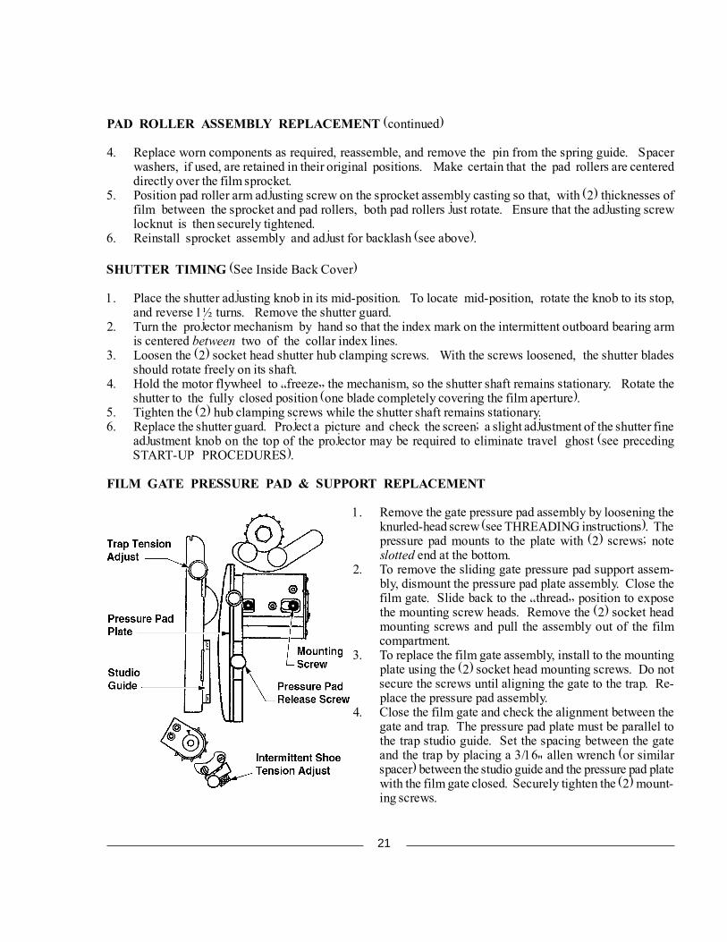
FILM GATE PRESSURE PAD & SUPPORT REPLACEMENT
1. Remove the gate pressure pad assembly by loosening theknurled-head screw (see THREADING instructions). Thepressure pad mounts to the plate with (2) screws; noteslotted end at the bottom.
2. To remove the sliding gate pressure pad support assem-bly, dismount the pressure pad plate assembly. Close thefilm gate. Slide back to the �thread� position to exposethe mounting screw heads. Remove the (2) socket headmounting screws and pull the assembly out of the filmcompartment.
3. To replace the film gate assembly, install to the mountingplate using the (2) socket head mounting screws. Do notsecure the screws until aligning the gate to the trap. Re-place the pressure pad assembly.
4. Close the film gate and check the alignment between thegate and trap. The pressure pad plate must be parallel tothe trap studio guide. Set the spacing between the gateand the trap by placing a 3/16" allen wrench (or similarspacer) between the studio guide and the pressure pad platewith the film gate closed. Securely tighten the (2) mount-ing screws.
21
SHUTTER REPLACEMENT
Remove the shutter guard. Disconnect the linkage to the changeover douser. Remove the (4) sockethead mounting screws from the rear cover casting, and dismount the cover. Loosen the (2) shutter hubclamping screws and dismount shutter. Install the replacement shutter and set shutter time as detailed in thepreceding section. Replace the rear cover, douser linkage, and shutter guard.
AUTOMATIC LENS TURRET
1. Check for correct contact between the turret drive tire and the driven indexing plate. Clean surfaces toprevent dust and dirt build-up; replace O-ring tire(s) if cracked or worn. Do not lubricate.
2. Clean the grooves in the (3) indexing plate ball bearings. The top bearing is mounted to an eccentricbushing to permit adjustment; take up any slack as required.
3. Check the (2) coil expansion springs on the index stop pin. Replace with new, matched pair if stretchedor worn. Check the expansion spring on the motor mount and replace if stretched.
4. A headless set screw in the center of the turret catch (mounted to the main frame) acts as a deadstop forturret closure. Tighten this screw as required to remove any play from the turret when closed, yet allowingthe turret to latch securely. Tighten the 1/4-20 hex nut to lock this adjustment.NOTE: Do not attempt to correct �keystoning� by setting this deadstop screw to offset the projectionlenses. Lenses must remain on optical center for correct focus.
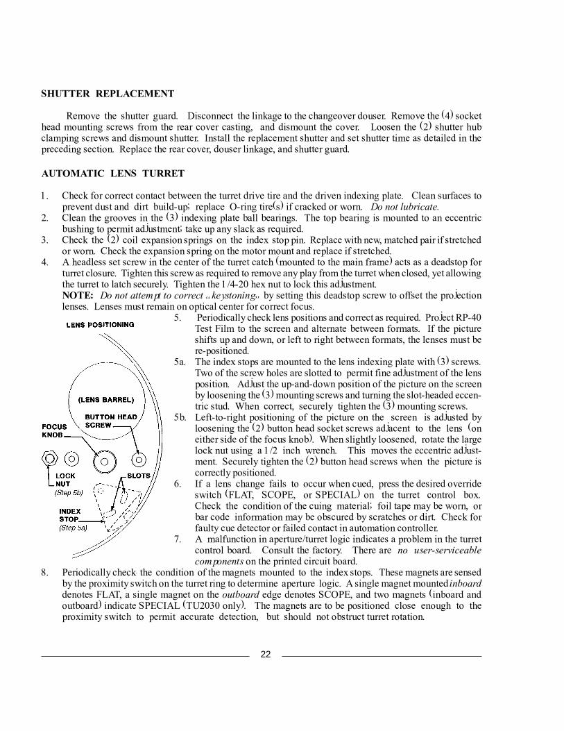
5. Periodically check lens positions and correct as required. Project RP-40Test Film to the screen and alternate between formats. If the pictureshifts up and down, or left to right between formats, the lenses must bere-positioned.
5a. The index stops are mounted to the lens indexing plate with (3) screws.Two of the screw holes are slotted to permit fine adjustment of the lensposition. Adjust the up-and-down position of the picture on the screenby loosening the (3) mounting screws and turning the slot-headed eccen-tric stud. When correct, securely tighten the (3) mounting screws.
5b. Left-to-right positioning of the picture on the screen is adjusted byloosening the (2) button head socket screws adjacent to the lens (oneither side of the focus knob). When slightly loosened, rotate the largelock nut using a 1/2 inch wrench. This moves the eccentric adjust-ment. Securely tighten the (2) button head screws when the picture iscorrectly positioned.
6. If a lens change fails to occur when cued, press the desired overrideswitch (FLAT, SCOPE, or SPECIAL) on the turret control box.Check the condition of the cuing material; foil tape may be worn, orbar code information may be obscured by scratches or dirt. Check forfaulty cue detector or failed contact in automation controller.
7. A malfunction in aperture/turret logic indicates a problem in the turretcontrol board. Consult the factory. There are no user-serviceablecomponents on the printed circuit board.
8. Periodically check the condition of the magnets mounted to the index stops. These magnets are sensedby the proximity switch on the turret ring to determine aperture logic. A single magnet mounted inboarddenotes FLAT, a single magnet on the outboard edge denotes SCOPE, and two magnets (inboard andoutboard) indicate SPECIAL (TU2030 only). The magnets are to be positioned close enough to theproximity switch to permit accurate detection, but should not obstruct turret rotation.
22
AUTOMATIC LENS TURRET (continued)
9. Two L.E.D. indicators on the control cabinet display operation of the aperture-sensing proximity switch.When the upper L.E.D. is illuminated, the proximity switch is sensing the inboard magnet, and setting theFLAT aperture. The lower L.E.D. glows when the proximity switch senses the outboard magnet, andactuates the SCOPE aperture. Both L.E.D.�s glowing simultaneously indicates that the proximity switchsenses two magnets, thereby setting the SPECIAL aperture (third lens, when used). Failure of the L.E.D.and/or failure of the aperture to cycle means that the magnets or the proximity switch are loose or out ofalignment; adjust as required. Periodically clean the surfaces of the magnets to allow good conduction.
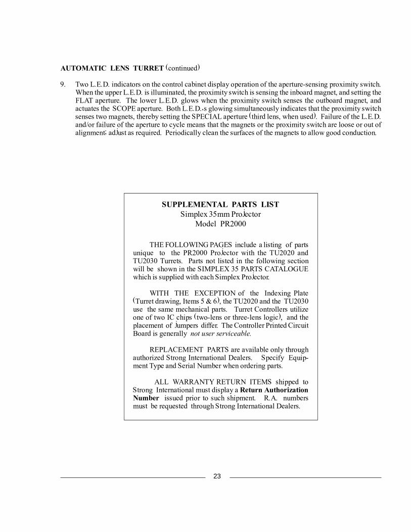
SUPPLEMENTAL PARTS LISTSimplex 35mm Projector
Model PR2000
THE FOLLOWING PAGES include a listing of partsunique to the PR2000 Projector with the TU2020 andTU2030 Turrets. Parts not listed in the following sectionwill be shown in the SIMPLEX 35 PARTS CATALOGUEwhich is supplied with each Simplex Projector.
WITH THE EXCEPTION of the Indexing Plate(Turret drawing, Items 5 & 6), the TU2020 and the TU2030use the same mechanical parts. Turret Controllers utilizeone of two IC chips (two-lens or three-lens logic), and theplacement of jumpers differ. The Controller Printed CircuitBoard is generally not user serviceable.
REPLACEMENT PARTS are available only throughauthorized Strong International Dealers. Specify Equip-ment Type and Serial Number when ordering parts.
ALL WARRANTY RETURN ITEMS shipped toStrong International must display a Return AuthorizationNumber issued prior to such shipment. R.A. numbersmust be requested through Strong International Dealers.
23
1
23
4
5
6
789
1011 12
13
1415
1617
18192021
22
23
201918
17
24
2526
2728
29
3130
32
33
34
35
3637
24
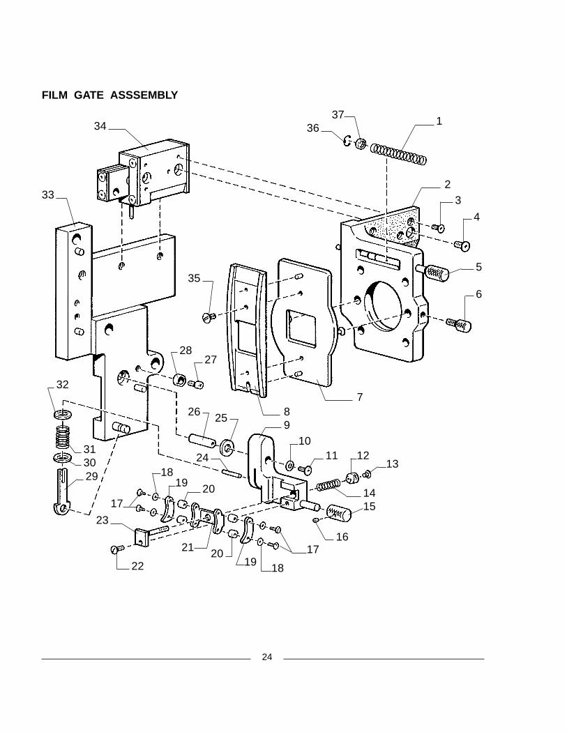
FILM GATE ASSSEMBLY
25
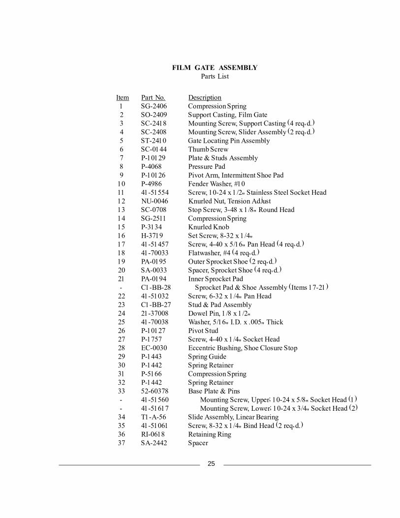
FILM GATE ASSEMBLYParts List
Item Part No. Description 1 SG-2406 Compression Spring 2 SO-2409 Support Casting, Film Gate 3 SC-2418 Mounting Screw, Support Casting (4 req�d.) 4 SC-2408 Mounting Screw, Slider Assembly (2 req�d.) 5 ST-2410 Gate Locating Pin Assembly 6 SC-0144 Thumb Screw 7 P-10129 Plate & Studs Assembly 8 P-4068 Pressure Pad 9 P-10126 Pivot Arm, Intermittent Shoe Pad 10 P-4986 Fender Washer, #10 11 41-51554 Screw, 10-24 x 1/2" Stainless Steel Socket Head 12 NU-0046 Knurled Nut, Tension Adjust 13 SC-0708 Stop Screw, 3-48 x 1/8" Round Head 14 SG-2511 Compression Spring 15 P-3134 Knurled Knob 16 H-3719 Set Screw, 8-32 x 1/4" 17 41-51457 Screw, 4-40 x 5/16" Pan Head (4 req�d.) 18 41-70033 Flatwasher, #4 (4 req�d.) 19 PA-0195 Outer Sprocket Shoe (2 req�d.) 20 SA-0033 Spacer, Sprocket Shoe (4 req�d.) 21 PA-0194 Inner Sprocket Pad - C1-BB-28 Sprocket Pad & Shoe Assembly (Items 17-21) 22 41-51032 Screw, 6-32 x 1/4" Pan Head 23 C1-BB-27 Stud & Pad Assembly 24 21-37008 Dowel Pin, 1/8 x 1/2" 25 41-70038 Washer, 5/16" I.D. x .005" Thick 26 P-10127 Pivot Stud 27 P-1757 Screw, 4-40 x 1/4" Socket Head 28 EC-0030 Eccentric Bushing, Shoe Closure Stop 29 P-1443 Spring Guide 30 P-1442 Spring Retainer 31 P-5166 Compression Spring 32 P-1442 Spring Retainer 33 52-60378 Base Plate & Pins - 41-51560 Mounting Screw, Upper; 10-24 x 5/8" Socket Head (1) - 41-51617 Mounting Screw, Lower; 10-24 x 3/4" Socket Head (2) 34 T1-A-56 Slide Assembly, Linear Bearing 35 41-51061 Screw, 8-32 x 1/4" Bind Head (2 req�d.) 36 RI-0618 Retaining Ring 37 SA-2442 Spacer
26
1
23
45
6
78
910
1112
1314
15 16
1718
12
19 2021
2223
24
25
1922
21
26
27
28 2930
31
2031
3233
34
3536
37
3839
1940
41
42
4344
45
46
474849
50
51
52
5354
55
5657
5859
6061 62 63
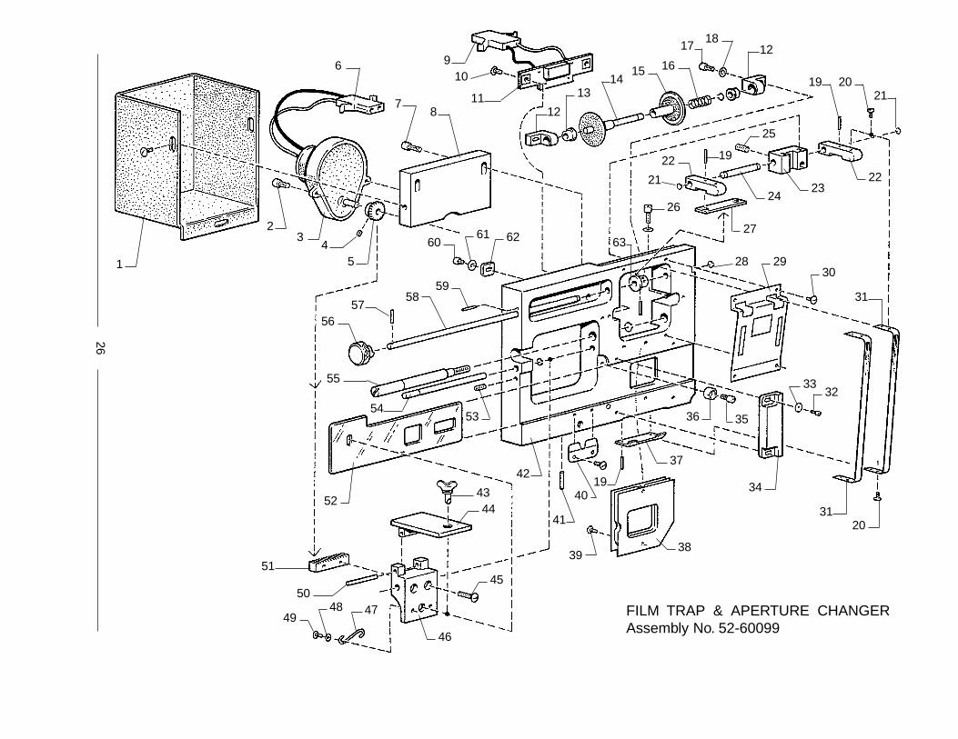
FILM TRAP & APERTURE CHANGERAssembly No. 52-60099
27
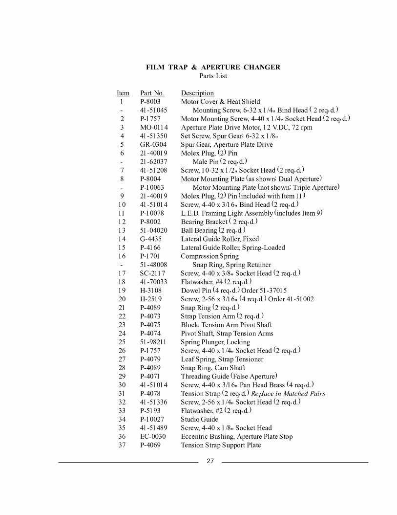
FILM TRAP & APERTURE CHANGERParts List
Item Part No. Description 1 P-8003 Motor Cover & Heat Shield - 41-51045 Mounting Screw, 6-32 x 1/4" Bind Head ( 2 req�d.) 2 P-1757 Motor Mounting Screw, 4-40 x 1/4� Socket Head (2 req�d.) 3 MO-0114 Aperture Plate Drive Motor, 12 V.DC, 72 rpm 4 41-51350 Set Screw, Spur Gear; 6-32 x 1/8" 5 GR-0304 Spur Gear, Aperture Plate Drive 6 21-40019 Molex Plug, (2) Pin - 21-62037 Male Pin (2 req�d.) 7 41-51208 Screw, 10-32 x 1/2" Socket Head (2 req�d.) 8 P-8004 Motor Mounting Plate (as shown; Dual Aperture) - P-10063 Motor Mounting Plate (not shown; Triple Aperture) 9 21-40019 Molex Plug, (2) Pin (included with Item 11) 10 41-51014 Screw, 4-40 x 3/16" Bind Head (2 req�d.) 11 P-10078 L.E.D. Framing Light Assembly (includes Item 9) 12 P-8002 Bearing Bracket ( 2 req�d.) 13 51-04020 Ball Bearing (2 req�d.) 14 G-4435 Lateral Guide Roller, Fixed 15 P-4166 Lateral Guide Roller, Spring-Loaded 16 P-1701 Compression Spring - 51-48008 Snap Ring, Spring Retainer 17 SC-2117 Screw, 4-40 x 3/8" Socket Head (2 req�d.) 18 41-70033 Flatwasher, #4 (2 req�d.) 19 H-3108 Dowel Pin (4 req�d.) Order 51-37015 20 H-2519 Screw, 2-56 x 3/16" (4 req�d.) Order 41-51002 21 P-4089 Snap Ring (2 req�d.) 22 P-4073 Strap Tension Arm (2 req�d.) 23 P-4075 Block, Tension Arm Pivot Shaft 24 P-4074 Pivot Shaft, Strap Tension Arms 25 51-98211 Spring Plunger, Locking 26 P-1757 Screw, 4-40 x 1/4" Socket Head (2 req�d.) 27 P-4079 Leaf Spring, Strap Tensioner 28 P-4089 Snap Ring, Cam Shaft 29 P-4071 Threading Guide (False Aperture) 30 41-51014 Screw, 4-40 x 3/16" Pan Head Brass (4 req�d.) 31 P-4078 Tension Strap (2 req�d.) Replace in Matched Pairs 32 41-51336 Screw, 2-56 x 1/4" Socket Head (2 req�d.) 33 P-5193 Flatwasher, #2 (2 req�d.) 34 P-10027 Studio Guide 35 41-51489 Screw, 4-40 x 1/8" Socket Head 36 EC-0030 Eccentric Bushing, Aperture Plate Stop 37 P-4069 Tension Strap Support Plate

28
Item Part No. Description 38 G-2614 Aperture Heat Shield, Air Cooled - G-4400 Aperture Heat Shield, Water Cooled (not shown) 39 41-51014 Screw, 4-40 x 3/16" Pan Head (2 req�d.) 40 51-10013 Aperture Plate Clamping Spring - 41-51615 Mounting Screw, 8-32 x 1/4" Bind Head (2 req�d.) 41 21-37004 Roll Pin, 1/8 x 1/2" 42 P-8000 Base Plate, Machined (as shown; Dual Aperture) - P-10044 Base Plate (not shown; Triple Aperture) - P-10045 Plate Extension (not shown; for P-10044) 43 ST-2474 Latching Stud, Wing Head (with Item 47) - BU-1366 Bushing - RI-0627 Stud Retaining Ring 44 CP-0921 Hinged Plate, Aperture Drive 45 41-51022 Mounting Screw (for Item 51), 4-40 x 5/8" Bind Head (2 req�d.) 46 BR-1371 Slider Bracket, Aperture Drive 47 SG-2475 Catch Spring (with Item 43) 48 WA-0379 Washer, #3 (2 req�d.) 49 41-51493 Screw, 3-48 x 3/16" Fillister Head (2 req�d.) 50 PN-1294 Hinge Pin 51 RK-0562 Rack Gear, Dual Aperture Drive - P-10060 Rack Gear, Triple Aperture Drive (not shown) 52 P-8005 Dual Aperture Plate - P-10043 Triple Aperture Plate (not shown) 53 41-51503 Set Screw, Aperture Plate Stop; 8-32 x 3/8" 54 RD-0626 Slide Rod, Dual Aperture Drive - P-10061 Slide Rod, Triple Aperture Drive (not shown) - RI-0828 Retaining Ring, Slide Rod 55 P-1981 Trap Mounting Screw, Captive - P-1556 Retaining Ring, Captive Screw 56 P-4077 Knurled Knob, Trap Tension Adjust 57 H-3107 Knob Retaining Pin, 3/64 x 5/16" 58 P-9831 Cam Shaft, Trap Tension 59 H-3108 Roll Pin, .052 x 5/16" 60 P-1757 Screw, 4-40 x 1/4" Socket Head 61 41-70033 Flatwasher, #4 62 P-8001 Fixed Roller Bracket Stop Plate, Brass 63 P-4092 Tensioning Cam - H-3107 Retaining Pin, Cam
TRIPLE APERTURE PLATE PARTS (NOT SHOWN)
P-10069 SolenoidP-10062 Aperture CamP-10068 Pivot RodSG-2405 Spring82-20076 Pivot Lock
FILM TRAP & APERTURE CHANGERParts List (continued)
29
1
2
34
5
6
7
8
9
101171213
14
15
16
17 18
1920
2122
23
2425
26272829
30
32
33
3134
35
36373839
40 4142
4344
45
4647
48
49
5051
52
53 54
52
55
5657
29 28 5826
3059
60
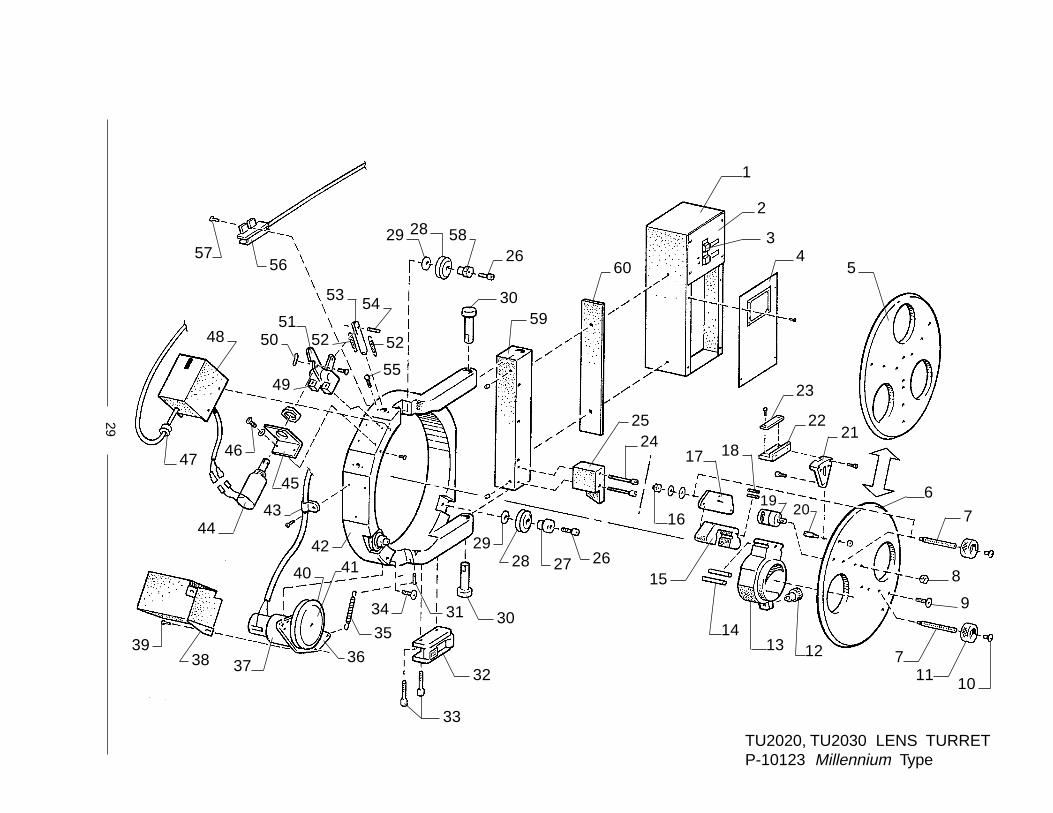
TU2020, TU2030 LENS TURRETP-10123 Millennium Type
30
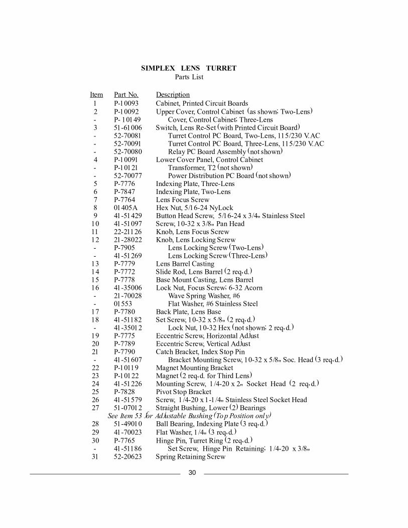
SIMPLEX LENS TURRETParts List
Item Part No. Description 1 P-10093 Cabinet, Printed Circuit Boards 2 P-10092 Upper Cover, Control Cabinet (as shown; Two-Lens) - P- 10149 Cover, Control Cabinet; Three-Lens 3 51-61006 Switch, Lens Re-Set (with Printed Circuit Board) - 52-70081 Turret Control PC Board, Two-Lens, 115/230 V.AC - 52-70091 Turret Control PC Board, Three-Lens, 115/230 V.AC - 52-70080 Relay PC Board Assembly (not shown) 4 P-10091 Lower Cover Panel, Control Cabinet - P-10121 Transformer, T2 (not shown) - 52-70077 Power Distribution PC Board (not shown) 5 P-7776 Indexing Plate, Three-Lens 6 P-7847 Indexing Plate, Two-Lens 7 P-7764 Lens Focus Screw 8 01405A Hex Nut, 5/16-24 NyLock 9 41-51429 Button Head Screw, 5/16-24 x 3/4" Stainless Steel 10 41-51097 Screw, 10-32 x 3/8" Pan Head 11 22-21126 Knob, Lens Focus Screw 12 21-28022 Knob, Lens Locking Screw - P-7905 Lens Locking Screw (Two-Lens) - 41-51269 Lens Locking Screw (Three-Lens) 13 P-7779 Lens Barrel Casting 14 P-7772 Slide Rod, Lens Barrel (2 req�d.) 15 P-7778 Base Mount Casting, Lens Barrel 16 41-35006 Lock Nut, Focus Screw; 6-32 Acorn - 21-70028 Wave Spring Washer, #6 - 01553 Flat Washer, #6 Stainless Steel 17 P-7780 Back Plate, Lens Base 18 41-51182 Set Screw, 10-32 x 5/8" (2 req�d.) - 41-35012 Lock Nut, 10-32 Hex (not shown; 2 req�d.) 19 P-7775 Eccentric Screw, Horizontal Adjust 20 P-7789 Eccentric Screw, Vertical Adjust 21 P-7790 Catch Bracket, Index Stop Pin - 41-51607 Bracket Mounting Screw, 10-32 x 5/8" Soc. Head (3 req�d.) 22 P-10119 Magnet Mounting Bracket 23 P-10122 Magnet (2 req�d. for Third Lens) 24 41-51226 Mounting Screw, 1/4-20 x 2" Socket Head (2 req�d.) 25 P-7828 Pivot Stop Bracket 26 41-51579 Screw, 1/4-20 x 1-1/4" Stainless Steel Socket Head 27 51-07012 Straight Bushing, Lower (2) Bearings
See Item 53 for Adjustable Bushing (Top Position only) 28 51-49010 Ball Bearing, Indexing Plate (3 req�d.) 29 41-70023 Flat Washer, 1/4" (3 req�d.) 30 P-7765 Hinge Pin, Turret Ring (2 req�d.) - 41-51186 Set Screw, Hinge Pin Retaining; 1/4-20 x 3/8" 31 52-20623 Spring Retaining Screw
31
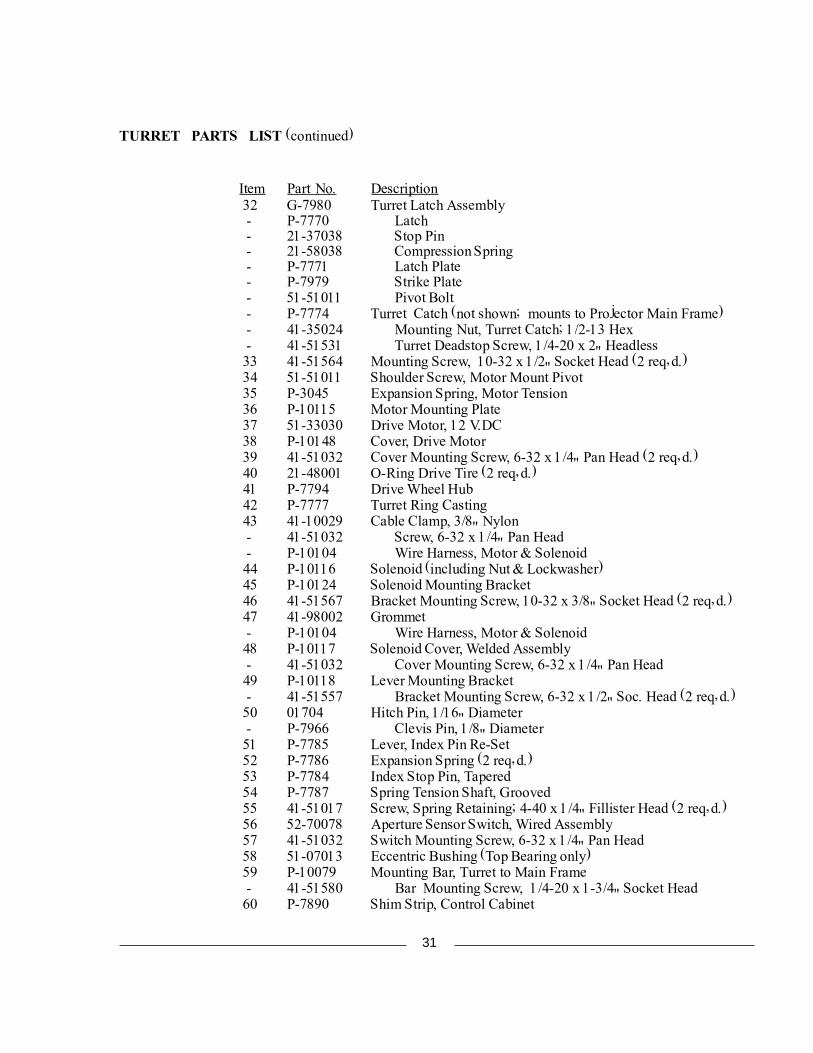
TURRET PARTS LIST (continued)
Item Part No. Description 32 G-7980 Turret Latch Assembly - P-7770 Latch - 21-37038 Stop Pin - 21-58038 Compression Spring - P-7771 Latch Plate - P-7979 Strike Plate - 51-51011 Pivot Bolt - P-7774 Turret Catch (not shown; mounts to Projector Main Frame) - 41-35024 Mounting Nut, Turret Catch; 1/2-13 Hex - 41-51531 Turret Deadstop Screw, 1/4-20 x 2" Headless 33 41-51564 Mounting Screw, 10-32 x 1/2" Socket Head (2 req�d.) 34 51-51011 Shoulder Screw, Motor Mount Pivot 35 P-3045 Expansion Spring, Motor Tension 36 P-10115 Motor Mounting Plate 37 51-33030 Drive Motor, 12 V.DC 38 P-10148 Cover, Drive Motor 39 41-51032 Cover Mounting Screw, 6-32 x 1/4" Pan Head (2 req�d.) 40 21-48001 O-Ring Drive Tire (2 req�d.) 41 P-7794 Drive Wheel Hub 42 P-7777 Turret Ring Casting 43 41-10029 Cable Clamp, 3/8" Nylon - 41-51032 Screw, 6-32 x 1/4" Pan Head - P-10104 Wire Harness, Motor & Solenoid 44 P-10116 Solenoid (including Nut & Lockwasher) 45 P-10124 Solenoid Mounting Bracket 46 41-51567 Bracket Mounting Screw, 10-32 x 3/8" Socket Head (2 req�d.) 47 41-98002 Grommet - P-10104 Wire Harness, Motor & Solenoid 48 P-10117 Solenoid Cover, Welded Assembly - 41-51032 Cover Mounting Screw, 6-32 x 1/4" Pan Head 49 P-10118 Lever Mounting Bracket - 41-51557 Bracket Mounting Screw, 6-32 x 1/2" Soc. Head (2 req�d.) 50 01704 Hitch Pin, 1/16" Diameter - P-7966 Clevis Pin, 1/8" Diameter 51 P-7785 Lever, Index Pin Re-Set 52 P-7786 Expansion Spring (2 req�d.) 53 P-7784 Index Stop Pin, Tapered 54 P-7787 Spring Tension Shaft, Grooved 55 41-51017 Screw, Spring Retaining; 4-40 x 1/4" Fillister Head (2 req�d.) 56 52-70078 Aperture Sensor Switch, Wired Assembly 57 41-51032 Switch Mounting Screw, 6-32 x 1/4" Pan Head 58 51-07013 Eccentric Bushing (Top Bearing only) 59 P-10079 Mounting Bar, Turret to Main Frame - 41-51580 Bar Mounting Screw, 1/4-20 x 1-3/4" Socket Head 60 P-7890 Shim Strip, Control Cabinet
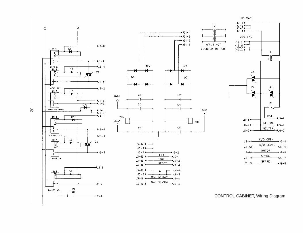
CONTROL CABINET, Wiring Diagram
32
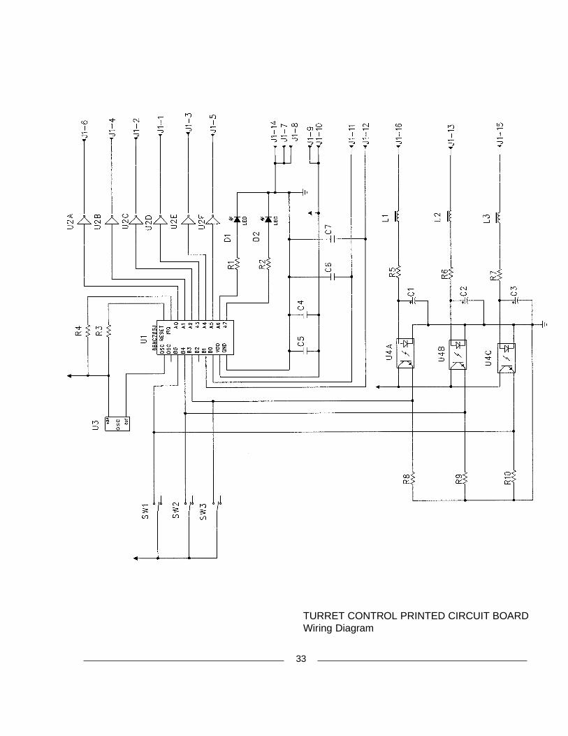
TURRET CONTROL PRINTED CIRCUIT BOARDWiring Diagram
33


STRONGINTERNATIONALa division of Ballantyne of Omaha, Inc.
4350 McKinley StreetOmaha, Nebraska 68112 USATel 402/453-4444 • Fax 402/453-7238
MODEL PR2000Millennium
with TU2020/2030 Turret