Embed Size (px)
Citation preview
F
M E T A L F A B R I C A T I N G M A C H I N E R Y
innovative technologies.
FIBERMAK Momentum Gen-2New Generation Fiber Laser
Innovative Technologies | www.ermaksan.com.tr | Laser Series
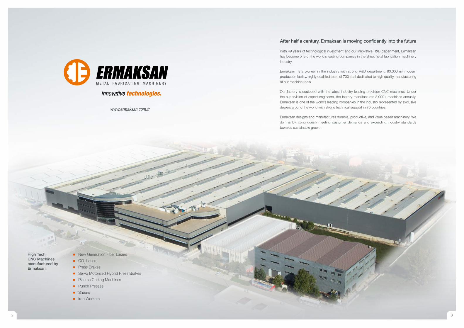
High Tech CNC Machines manufactured by Ermaksan;
� New Generation Fiber Lasers
� CO2 Lasers
� Press Brakes
� Servo Motorized Hybrid Press Brakes
� Plasma Cutting Machines
� Punch Presses
� Shears
� Iron Workers
www.ermaksan.com.tr
M E T A L F A B R I C A T I N G M A C H I N E R Y
innovative technologies.
After half a century, Ermaksan is moving confidently into the future
With 49 years of technological investment and our innovative R&D department, Ermaksan
has become one of the world’s leading companies in the sheetmetal fabrication machinery
industry.
Ermaksan is a pioneer in the industry with strong R&D department, 80.000 m2 modern
production facility, highly qualified team of 700 staff dedicated to high quality manufacturing
of our machine tools.
Our factory is equipped with the latest industry leading precision CNC machines. Under
the supervision of expert engineers, the factory manufactures 3,000+ machines annually.
Ermaksan is one of the world’s leading companies in the industry represented by exclusive
dealers around the world with strong technical support in 70 countries.
Ermaksan designs and manufactures durable, productive, and value based machinery. We
do this by, continuously meeting customer demands and exceeding industry standards
towards sustainable growth.
2 3
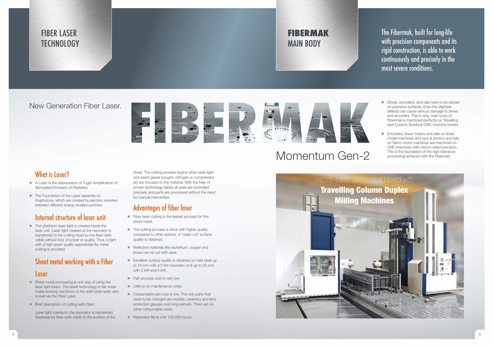
micron-rated precision achieved withTravelling Column Duplex
Milling Machines
FIBER LASER TECHNOLOGY
FIBERMAKMAIN BODY
Momentum Gen-2
New Generation Fiber Laser. � Drives, encoders, and rails have to be placed
on precision surfaces. Even the slightest defects can cause serious damage to drives and encoders. This is why, main body of Fibermak is machined perfectly on Travelling duel Column Soraluce CNC machine towers.
� Encoders, linear motors and rails on linear model machines and rack & pinions and rails on Servo motor machines are machined on CNC machines with micron-rated precision. This is the foundation of the high tolerance processing achieved with the Fibermak.
What is Laser? � A Laser is the abbreviation of “Light Amplification of
Stimulated Emission of Radiation
� The Foundation of the Laser depends on thephotons, which are created by electron transfers between different energy levelled particles.
Internal structure of laser unit � The ytterbium laser light is created inside the
laser unit. Laser light created at the resonator is transferred to the cutting head by the fiber-optic cable without loss of power or quality. Thus, a light with a high beam quality appropriate for metal cutting is provided.
Sheet metal working with a Fiber
Laser � Sheet metal processing is one way of using the
laser light beam. The latest technology in flat sheet metal working machinery is the solid state laser, also known as the Fiber Laser.
� Brief description of cutting with Fiber:
Laser light created in the resonator is transferred flawlessly by fiber-optic cable to the surface of the
sheet. The cutting process begins when laser light and assist gases (oxygen, nitrogen or compressed air) are focused on the material. With the help of proven technology tables all axes are controlled precisely and parts are processed without the need for manual intervention.
Advantages of fiber laser � Fiber laser cutting is the fastest process for thin
sheet metal.
� The cutting process is done with higher quality compared to other options. A “clean cut” surface quality is obtained.
� Reflective materials like aluminium, copper and brass can be cut with ease.
� Excellent surface quality is obtained on mild steel up to 15 mm with a 2 kW resonator and up to 20 mm with 3 kW and 4 kW.
� Part process cost is very low.
� Little to no maintenance costs.
� Consumable part cost is low. The only parts that need to be changed are nozzles, ceramics and lens protection glasses over long periods. There are no other consumable costs.
� Resonator life is over 100.000 hours.
The Fibermak, built for long-life with precision components and its rigid construction, is able to work continuously and precisely in the most severe conditions.
4 5
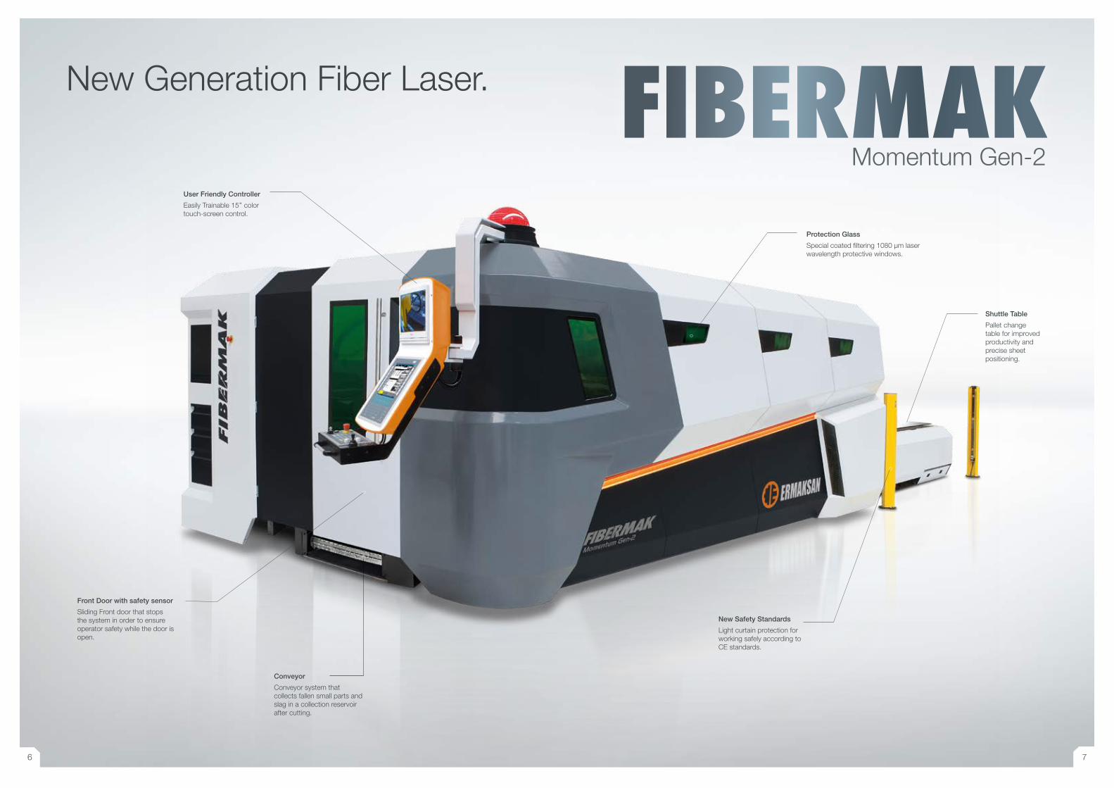
User Friendly Controller
Easily Trainable 15’’ color touch-screen control.
Front Door with safety sensor
Sliding Front door that stops the system in order to ensure operator safety while the door is open.
Conveyor
Conveyor system that collects fallen small parts and slag in a collection reservoir after cutting.
New Generation Fiber Laser.
Protection Glass
Special coated filtering 1080 μm laser wavelength protective windows.
New Safety Standards
Light curtain protection for working safely according to CE standards.
Shuttle Table
Pallet change table for improved productivity and precise sheet positioning.
FIBERMAKMomentum Gen-2
6 7
STANDARD EQUIPMENT
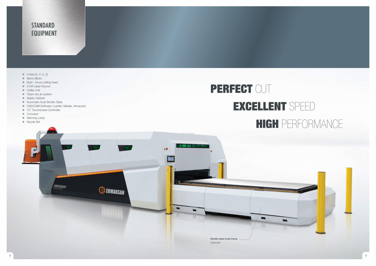
� 4 Axis (X, Y, U, Z) � Servo Motor � Auto - focus cutting head � 2 kW Laser Source � Chiller Unit � Clean-dry air system � Safety Cabinet � Automatic-Dual Shuttle Table � CAD/CAM Software ( Lantek, Metalix, Almacam) � 15’’ Touchscreen Controller � Conveyor � Warning Lamp � Nozzle Set
PERFECT CUT
EXCELLENT SPEED
HIGH PERFORMANCE
Shuttle table body frame
(Optional)
8 9
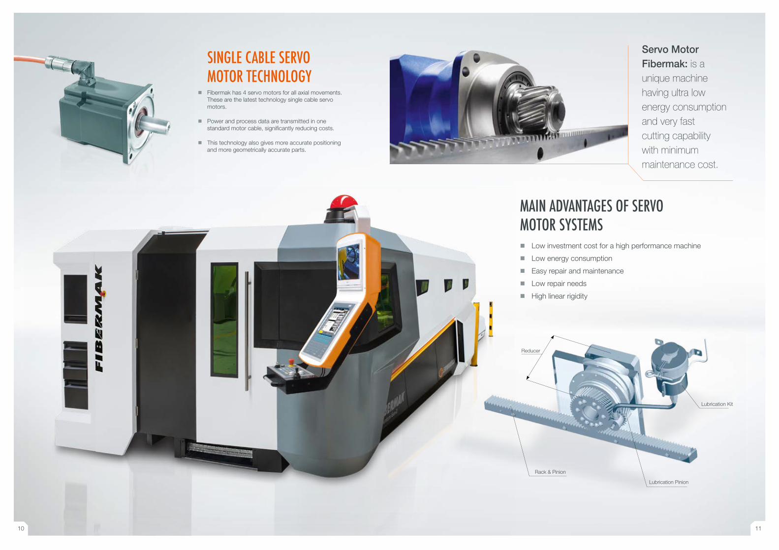
SINGLE CABLE SERVO MOTOR TECHNOLOGY
� Fibermak has 4 servo motors for all axial movements. These are the latest technology single cable servo motors.
� Power and process data are transmitted in one standard motor cable, significantly reducing costs.
� This technology also gives more accurate positioning and more geometrically accurate parts.
Servo Motor Fibermak: is a unique machine having ultra low energy consumption and very fast cutting capability with minimum maintenance cost.
MAIN ADVANTAGES OF SERVO MOTOR SYSTEMS
� Low investment cost for a high performance machine
� Low energy consumption
� Easy repair and maintenance
� Low repair needs
� High linear rigidity
Rack & Pinion
Lubrication Kit
Lubrication Pinion
Reducer
10 11
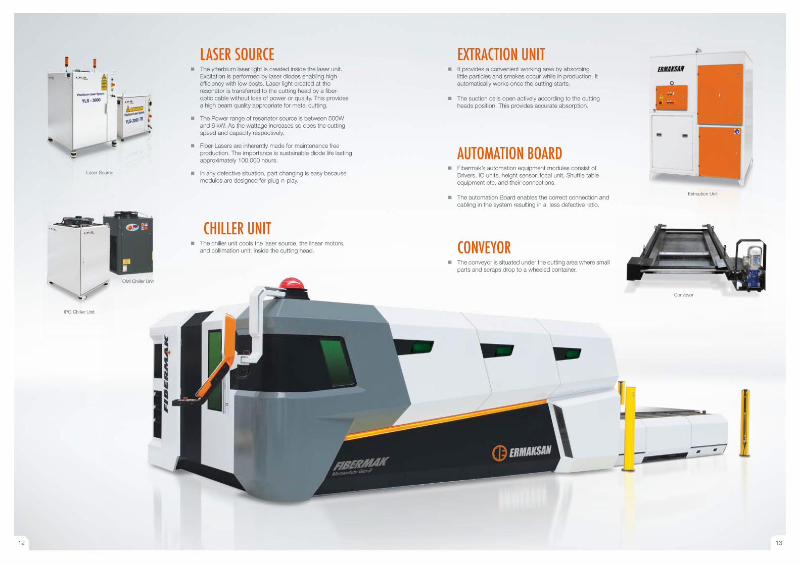
LASER SOURCE � The ytterbium laser light is created inside the laser unit.
Excitation is performed by laser diodes enabling high efficiency with low costs. Laser light created at the resonator is transferred to the cutting head by a fiber- optic cable without loss of power or quality. This provides a high beam quality appropriate for metal cutting.
� The Power range of resonator source is between 500W and 6 kW. As the wattage increases so does the cutting speed and capacity respectively.
� Fiber Lasers are inherently made for maintenance free production. The importance is sustainable diode life lasting approximately 100,000 hours.
� In any defective situation, part changing is easy because modules are designed for plug-n-play.
EXTRACTION UNIT � It provides a convenient working area by absorbing
little particles and smokes occur while in production. It automatically works once the cutting starts.
� The suction cells open actively according to the cutting heads position. This provides accurate absorption.
AUTOMATION BOARD � Fibermak’s automation equipment modules consist of
Drivers, IO units, height sensor, focal unit, Shuttle table equipment etc. and their connections.
� The automation Board enables the correct connection and cabling in the system resulting in a less defective ratio.
Laser Source
Extraction Unit
CHILLER UNIT � The chiller unit cools the laser source, the linear motors,
and collimation unit: inside the cutting head. CONVEYOR � The conveyor is situated under the cutting area where small
parts and scraps drop to a wheeled container.
IPG Chiller Unit
OMI Chiller Unit
Conveyor
12 13
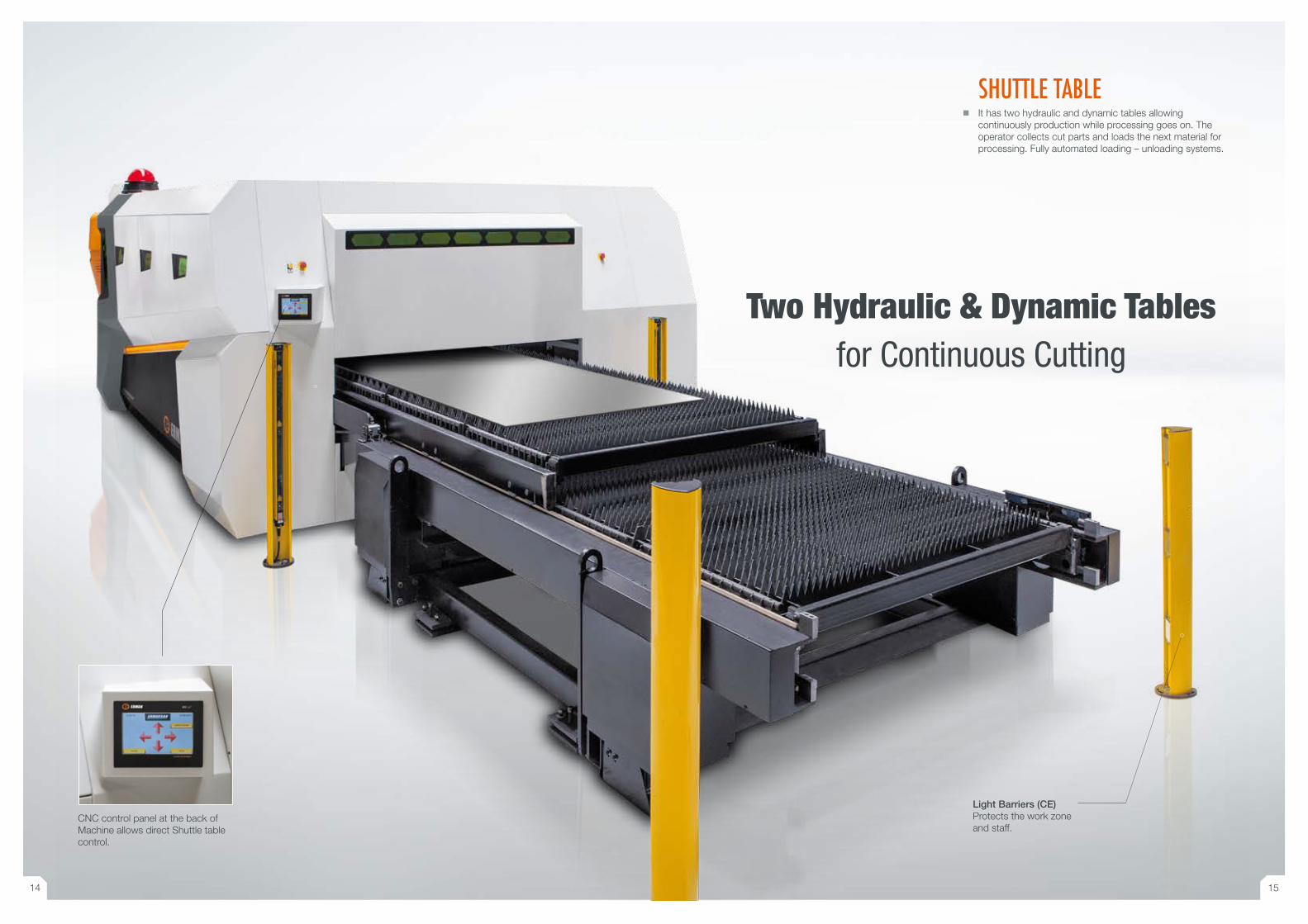
SHUTTLE TABLE � It has two hydraulic and dynamic tables allowing
continuously production while processing goes on. The operator collects cut parts and loads the next material for processing. Fully automated loading – unloading systems.
CNC control panel at the back of Machine allows direct Shuttle table control.
Two Hydraulic & Dynamic Tablesfor Continuous Cutting
Light Barriers (CE)Protects the work zone and staff.
14 15
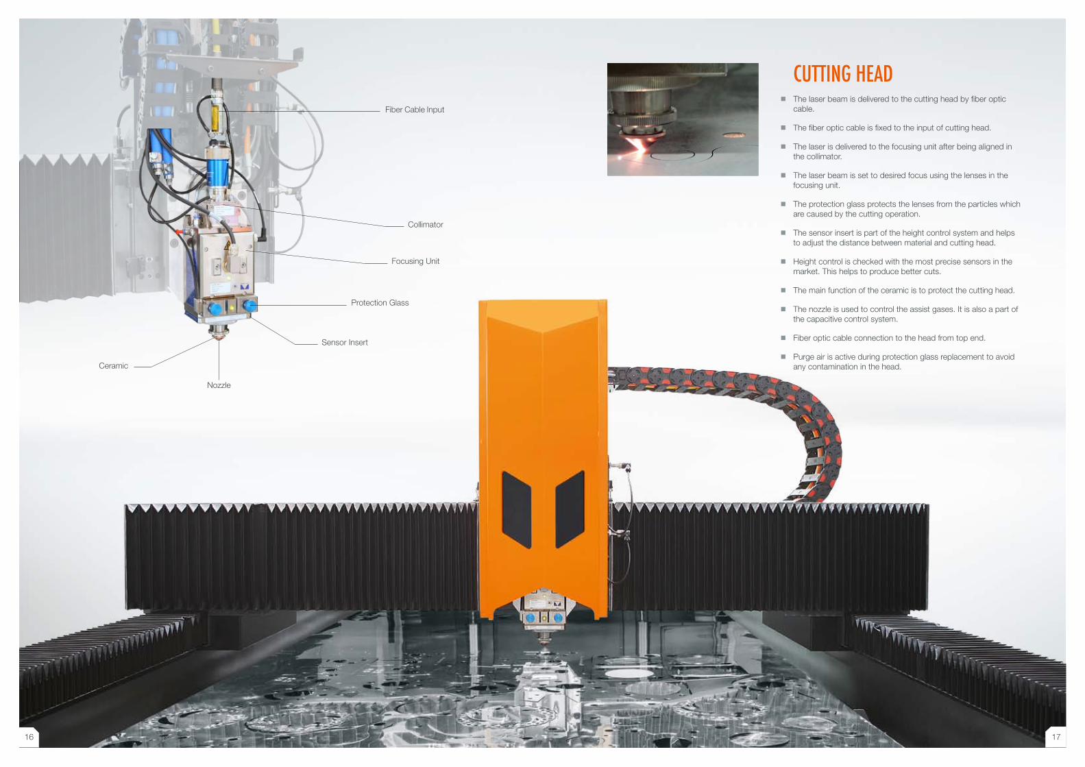
CUTTING HEAD � The laser beam is delivered to the cutting head by fiber optic
cable.
� The fiber optic cable is fixed to the input of cutting head.
� The laser is delivered to the focusing unit after being aligned in the collimator.
� The laser beam is set to desired focus using the lenses in the focusing unit.
� The protection glass protects the lenses from the particles which are caused by the cutting operation.
� The sensor insert is part of the height control system and helps to adjust the distance between material and cutting head.
� Height control is checked with the most precise sensors in the market. This helps to produce better cuts.
� The main function of the ceramic is to protect the cutting head.
� The nozzle is used to control the assist gases. It is also a part of the capacitive control system.
� Fiber optic cable connection to the head from top end.
� Purge air is active during protection glass replacement to avoid any contamination in the head.
Fiber Cable Input
Focusing Unit
Protection Glass
Collimator
Sensor Insert
Ceramic
Nozzle
16 17
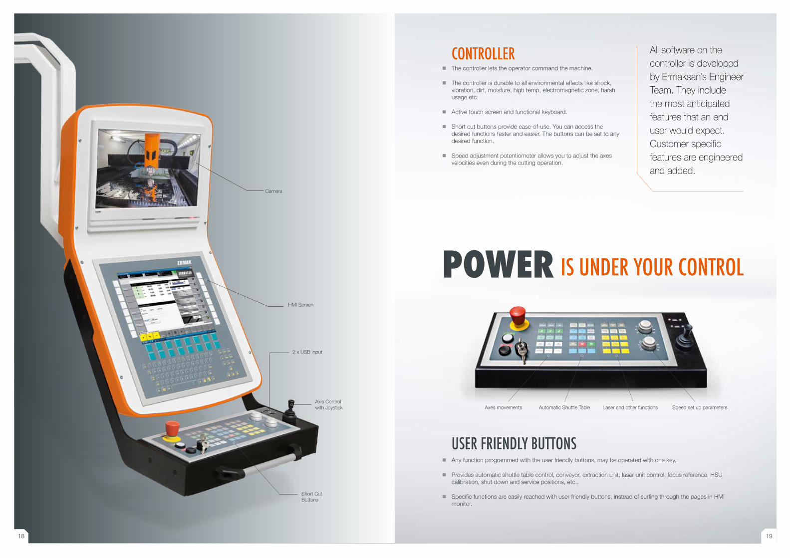
HMI Screen
Axis Control with Joystick
Short Cut Buttons
Camera
� Any function programmed with the user friendly buttons, may be operated with one key.
� Provides automatic shuttle table control, conveyor, extraction unit, laser unit control, focus reference, HSU calibration, shut down and service positions, etc..
� Specific functions are easily reached with user friendly buttons, instead of surfing through the pages in HMI monitor.
CONTROLLER � The controller lets the operator command the machine.
� The controller is durable to all environmental effects like shock, vibration, dirt, moisture, high temp, electromagnetic zone, harsh usage etc.
� Active touch screen and functional keyboard.
� Short cut buttons provide ease-of-use. You can access the desired functions faster and easier. The buttons can be set to any desired function.
� Speed adjustment potentiometer allows you to adjust the axes velocities even during the cutting operation.
USER FRIENDLY BUTTONS
All software on the controller is developed by Ermaksan’s Engineer Team. They include the most anticipated features that an end user would expect. Customer specific features are engineered and added.
Axes movements Automatic Shuttle Table Laser and other functions Speed set up parameters
POWER IS UNDER YOUR CONTROL
2 x USB input
18 19
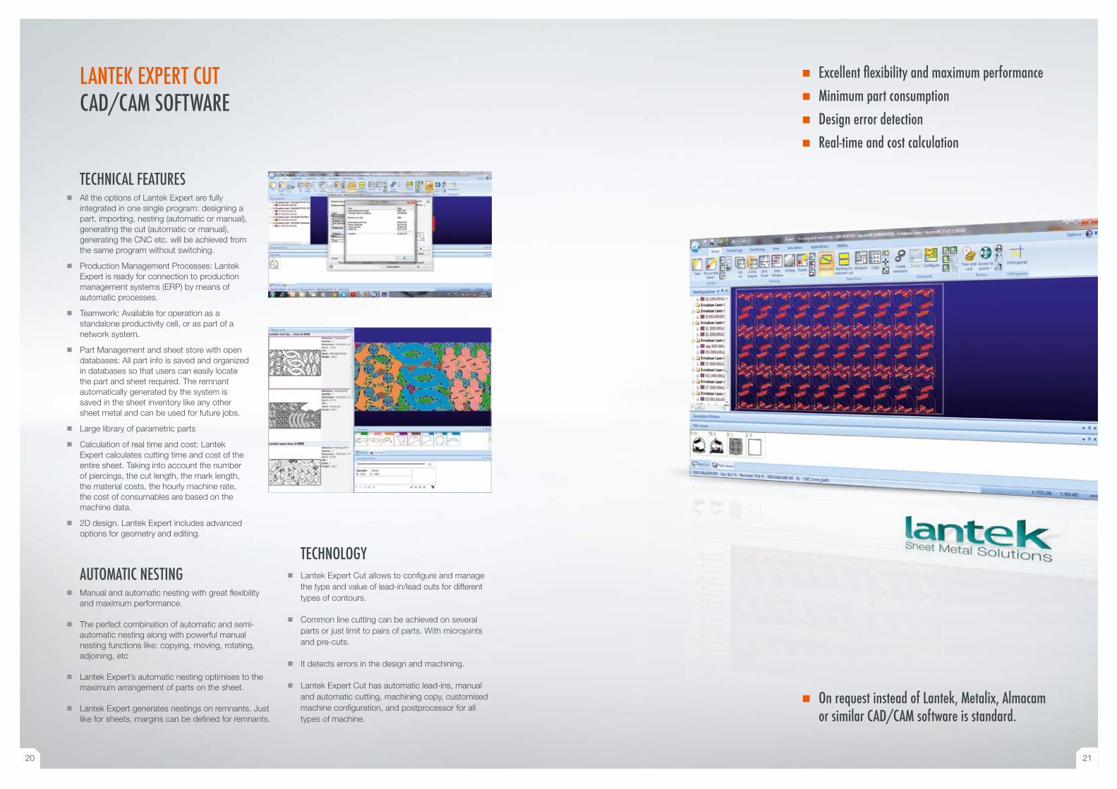
TECHNICAL FEATURES � All the options of Lantek Expert are fully
integrated in one single program: designing a part, importing, nesting (automatic or manual), generating the cut (automatic or manual), generating the CNC etc. will be achieved from the same program without switching.
� Production Management Processes: Lantek Expert is ready for connection to production management systems (ERP) by means of automatic processes.
� Teamwork: Available for operation as a standalone productivity cell, or as part of a network system.
� Part Management and sheet store with open databases: All part info is saved and organized in databases so that users can easily locate the part and sheet required. The remnant automatically generated by the system is saved in the sheet inventory like any other sheet metal and can be used for future jobs.
� Large library of parametric parts
� Calculation of real time and cost: Lantek Expert calculates cutting time and cost of the entire sheet. Taking into account the number of piercings, the cut length, the mark length, the material costs, the hourly machine rate, the cost of consumables are based on the machine data.
� 2D design. Lantek Expert includes advanced options for geometry and editing.
AUTOMATIC NESTING � Manual and automatic nesting with great flexibility
and maximum performance.
� The perfect combination of automatic and semi- automatic nesting along with powerful manual nesting functions like: copying, moving, rotating, adjoining, etc
� Lantek Expert’s automatic nesting optimises to the maximum arrangement of parts on the sheet.
� Lantek Expert generates nestings on remnants. Just like for sheets, margins can be defined for remnants.
TECHNOLOGY � Lantek Expert Cut allows to configure and manage
the type and value of lead-in/lead outs for different types of contours.
� Common line cutting can be achieved on several parts or just limit to pairs of parts. With microjoints and pre-cuts.
� It detects errors in the design and machining.
� Lantek Expert Cut has automatic lead-ins, manual and automatic cutting, machining copy, customised machine configuration, and postprocessor for all types of machine.
LANTEK EXPERT CUTCAD/CAM SOFTWARE
� Excellent flexibility and maximum performance � Minimum part consumption � Design error detection � Real-time and cost calculation
� On request instead of Lantek, Metalix, Almacam or similar CAD/CAM software is standard.
20 21
CUTTINGQUALITY High-Speed and
Excellent Quality Cuts
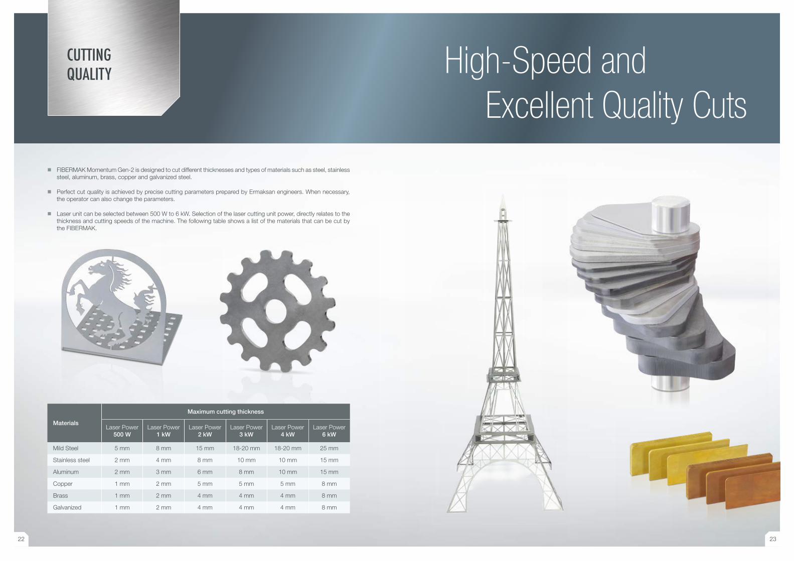
Materials
Maximum cutting thickness
Laser Power500 W
Laser Power1 kW
Laser Power2 kW
Laser Power3 kW
Laser Power4 kW
Laser Power6 kW
Mild Steel 5 mm 8 mm 15 mm 18-20 mm 18-20 mm 25 mm
Stainless steel 2 mm 4 mm 8 mm 10 mm 10 mm 15 mm
Aluminum 2 mm 3 mm 6 mm 8 mm 10 mm 15 mm
Copper 1 mm 2 mm 5 mm 5 mm 5 mm 8 mm
Brass 1 mm 2 mm 4 mm 4 mm 4 mm 8 mm
Galvanized 1 mm 2 mm 4 mm 4 mm 4 mm 8 mm
� FIBERMAK Momentum Gen-2 is designed to cut different thicknesses and types of materials such as steel, stainless steel, aluminum, brass, copper and galvanized steel.
� Perfect cut quality is achieved by precise cutting parameters prepared by Ermaksan engineers. When necessary, the operator can also change the parameters.
� Laser unit can be selected between 500 W to 6 kW. Selection of the laser cutting unit power, directly relates to the thickness and cutting speeds of the machine. The following table shows a list of the materials that can be cut by the FIBERMAK.
22 23
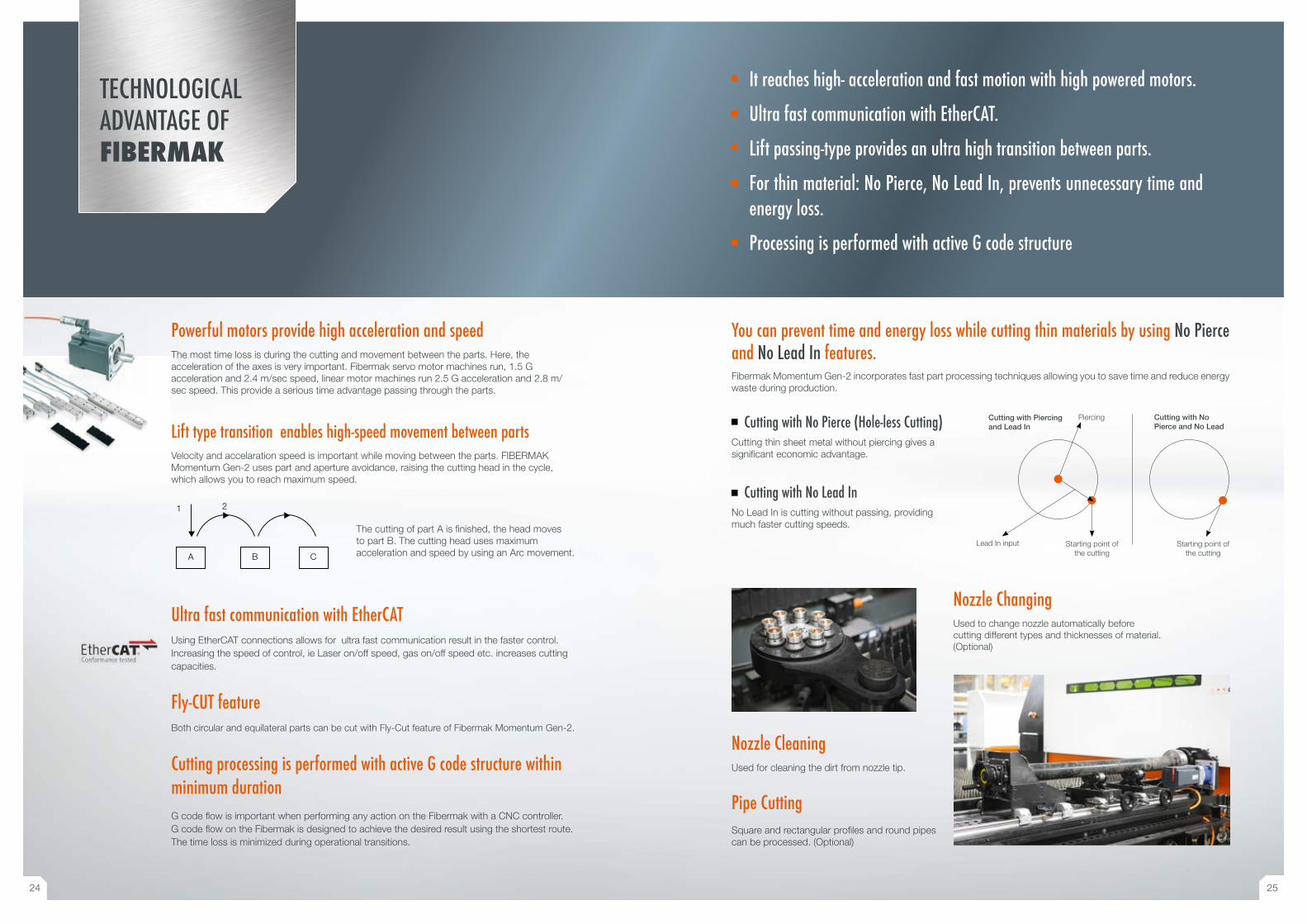
Powerful motors provide high acceleration and speedThe most time loss is during the cutting and movement between the parts. Here, the acceleration of the axes is very important. Fibermak servo motor machines run, 1.5 G acceleration and 2.4 m/sec speed, linear motor machines run 2.5 G acceleration and 2.8 m/sec speed. This provide a serious time advantage passing through the parts.
Lift type transition enables high-speed movement between partsVelocity and accelaration speed is important while moving between the parts. FIBERMAK Momentum Gen-2 uses part and aperture avoidance, raising the cutting head in the cycle, which allows you to reach maximum speed.
Ultra fast communication with EtherCATUsing EtherCAT connections allows for ultra fast communication result in the faster control. Increasing the speed of control, ie Laser on/off speed, gas on/off speed etc. increases cutting capacities.
Fly-CUT featureBoth circular and equilateral parts can be cut with Fly-Cut feature of Fibermak Momentum Gen-2.
Cutting processing is performed with active G code structure within minimum durationG code flow is important when performing any action on the Fibermak with a CNC controller. G code flow on the Fibermak is designed to achieve the desired result using the shortest route. The time loss is minimized during operational transitions.
The cutting of part A is finished, the head moves to part B. The cutting head uses maximum acceleration and speed by using an Arc movement.A B C
1 2
You can prevent time and energy loss while cutting thin materials by using No Pierce and No Lead In features.Fibermak Momentum Gen-2 incorporates fast part processing techniques allowing you to save time and reduce energy waste during production.
Cutting with No Pierce and No Lead
Starting point of the cutting
Cutting with Piercing and Lead In
Piercing
Lead In input Starting point of the cutting
It reaches high- acceleration and fast motion with high powered motors.
Ultra fast communication with EtherCAT.
Lift passing-type provides an ultra high transition between parts.
For thin material: No Pierce, No Lead In, prevents unnecessary time and energy loss.
Processing is performed with active G code structure
TECHNOLOGICALADVANTAGE OFFIBERMAK
Cutting with No Pierce (Hole-less Cutting)Cutting thin sheet metal without piercing gives a significant economic advantage.
Cutting with No Lead InNo Lead In is cutting without passing, providing much faster cutting speeds.
Nozzle CleaningUsed for cleaning the dirt from nozzle tip.
Pipe CuttingSquare and rectangular profiles and round pipes can be processed. (Optional)
Nozzle ChangingUsed to change nozzle automatically before cutting different types and thicknesses of material. (Optional)
24 25
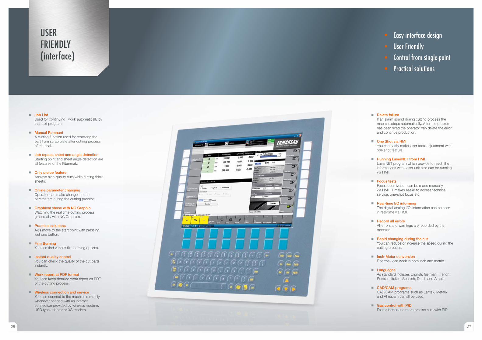
USER FRIENDLY (interface)
� Job List Used for continuing work automatically by the next program.
� Manual Remnant A cutting function used for removing the part from scrap plate after cutting process of material.
� Job repeat, sheet and angle detection Starting point and sheet angle detection are all features of the Fibermak.
� Only pierce featureAchieve high-quality cuts while cutting thick sheets.
� Online parameter changingOperator can make changes to the parameters during the cutting process.
� Graphical chase with NC Graphic Watching the real time cutting process graphically with NC Graphics.
� Practical solutionsAxis move to the start point with pressing just one button.
� Film BurningYou can find various film burning options.
� Instant quality controlYou can check the quality of the cut parts instantly.
� Work report at PDF formatYou can keep detailed work report as PDF of the cutting process.
� Wireless connection and serviceYou can connect to the machine remotely whenever needed with an Internet connection provided by wireless modem, USB type adapter or 3G modem.
Easy interface designUser FriendlyControl from single-pointPractical solutions
� Delete failureIf an alarm sound during cutting process the machine stops automatically. After the problem has been fixed the operator can delete the error and continue production.
� One Shot via HMI You can easily make laser focal adjustment with one shot feature.
� Running LaserNET from HMILaserNET program which provide to reach the informations with Laser unit also can be running via HMI.
� Focus testsFocus optimization can be made manually via HMI. IT makes easier to access technical service, one-shot focus etc.
� Real-time I/O informingThe digital-analog I/O information can be seen in real-time via HMI.
� Record all errorsAll errors and warnings are recorded by the machine.
� Rapid changing during the cutYou can reduce or increase the speed during the cutting process.
� Inch-Meter conversionFibermak can work in both inch and metric.
� LanguagesAs standard includes English, German, French, Russian, İtalian, Spanish, Dutch and Arabic.
� CAD/CAM programsCAD/CAM programs such as Lantek, Metalix and Almacam can all be used.
� Gas control with PIDFaster, better and more precise cuts with PID.
26 27
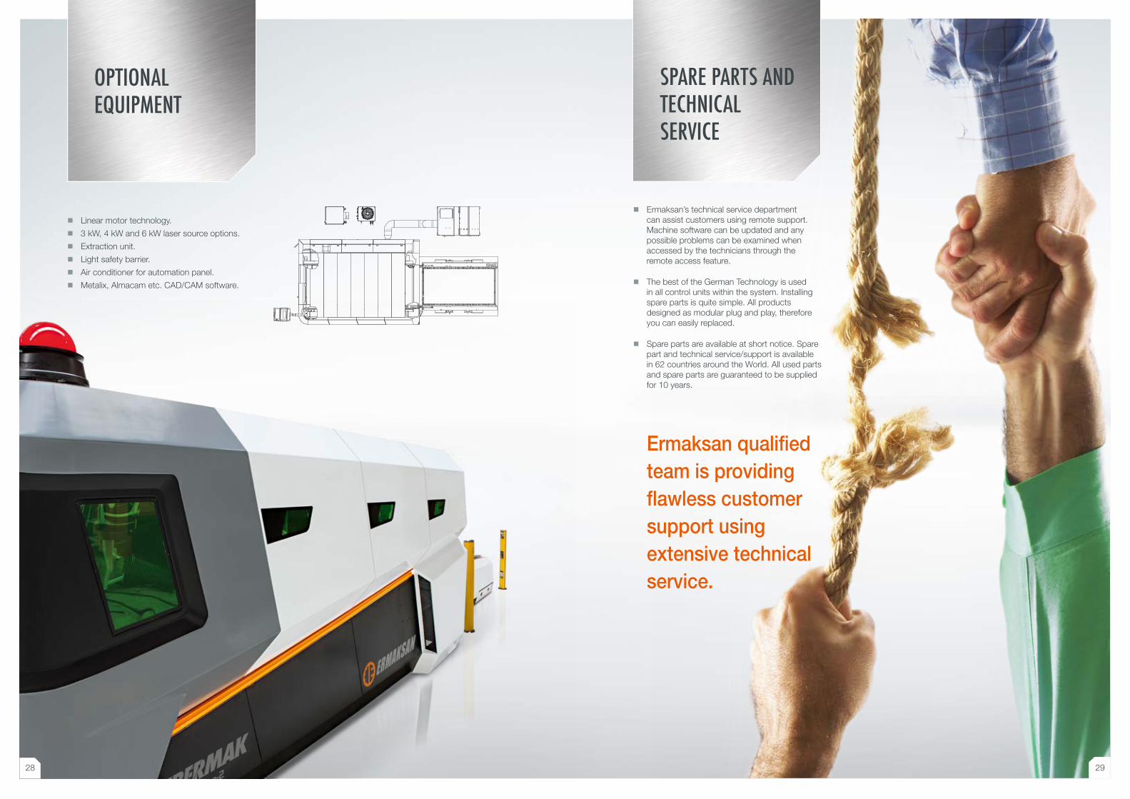
OPTIONAL EQUIPMENT
� Linear motor technology.
� 3 kW, 4 kW and 6 kW laser source options.
� Extraction unit.
� Light safety barrier.
� Air conditioner for automation panel.
� Metalix, Almacam etc. CAD/CAM software.
SPARE PARTS AND TECHNICAL SERVICE
� Ermaksan’s technical service department can assist customers using remote support. Machine software can be updated and any possible problems can be examined when accessed by the technicians through the remote access feature.
� The best of the German Technology is used in all control units within the system. Installing spare parts is quite simple. All products designed as modular plug and play, therefore you can easily replaced.
� Spare parts are available at short notice. Spare part and technical service/support is available in 62 countries around the World. All used parts and spare parts are guaranteed to be supplied for 10 years.
Ermaksan qualified team is providing flawless customer support using extensive technical service.
28 29
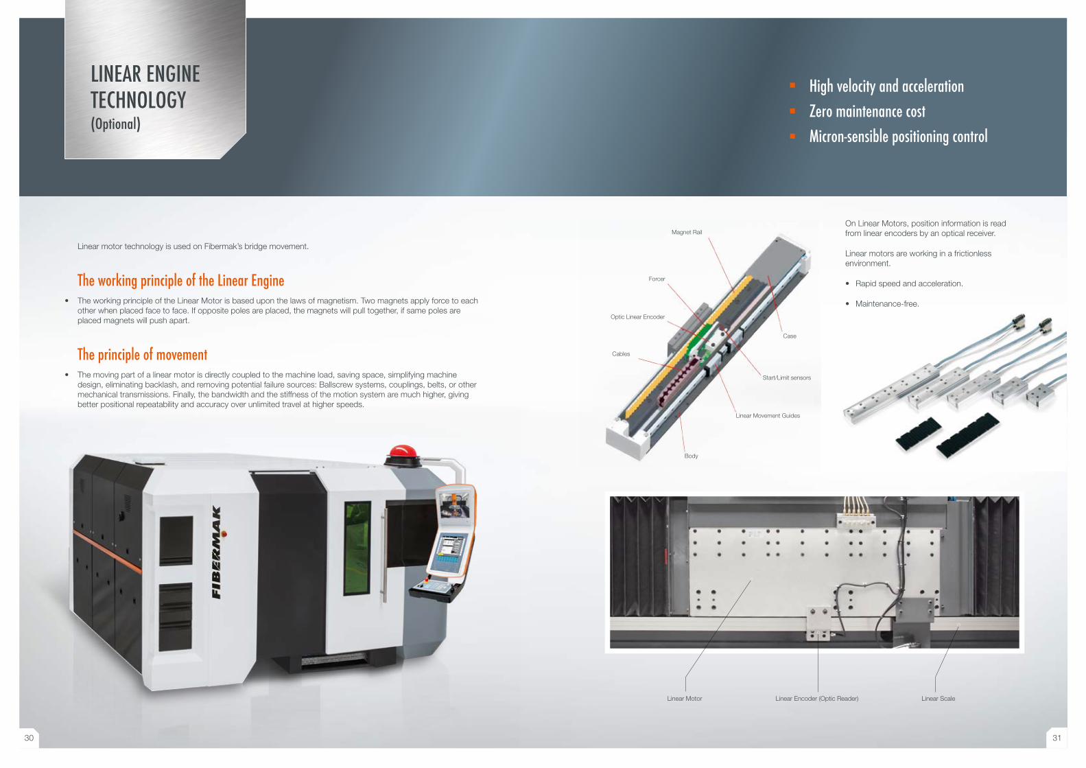
Linear motor technology is used on Fibermak’s bridge movement.
The working principle of the Linear Engine• The working principle of the Linear Motor is based upon the laws of magnetism. Two magnets apply force to each
other when placed face to face. If opposite poles are placed, the magnets will pull together, if same poles are placed magnets will push apart.
The principle of movement• The moving part of a linear motor is directly coupled to the machine load, saving space, simplifying machine
design, eliminating backlash, and removing potential failure sources: Ballscrew systems, couplings, belts, or other mechanical transmissions. Finally, the bandwidth and the stiffness of the motion system are much higher, giving better positional repeatability and accuracy over unlimited travel at higher speeds.
On Linear Motors, position information is read from linear encoders by an optical receiver.
Linear motors are working in a frictionless environment.
• Rapid speed and acceleration.
• Maintenance-free.
Magnet Rail
Forcer
Optic Linear Encoder
Cables
Body
Linear Movement Guides
Start/Limit sensors
Case
High velocity and accelerationZero maintenance costMicron-sensible positioning control
LINEAR ENGINE TECHNOLOGY (Optional)
Linear Motor Linear Encoder (Optic Reader) Linear Scale
30 31
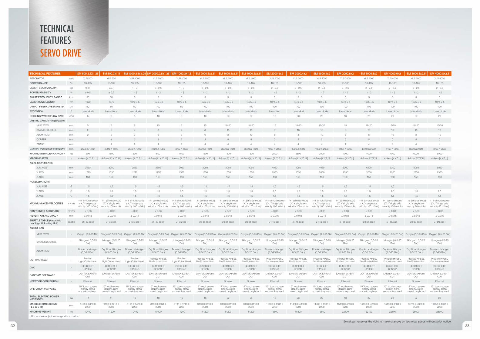
TECHNICAL FEATURES SM 500.2.5X1.25 SM 500.3x1.5 SM 1000.2.5x1.25 SM 2000.2.5x1.25 SM 1000.3x1.5 SM 2000.3x1.5 SM 3000.3x1.5 SM 4000.3x1.5 SM 2000.4x2 SM 3000.4x2 SM 4000.4x2 SM 2000.6x2 SM 3000.6x2 SM 4000.6x2 SM 3000.8x2,5 SM 4000.8x2,5
RESONATOR Watt YLR 500 YLR 500 YLR 1000 YLS 2000 YLR 1000 YLS 2000 YLS 3000 YLS 4000 YLS 2000 YLS 3000 YLS 4000 YLS 2000 YLS 3000 YLS 4000 YLS 3000 YLS 4000
POWER RANGE % 10-105 10-105 10-105 10-105 10-105 10-105 10-105 10-105 10-105 10-105 10-105 10-105 10-105 10-105 10-105 10-105
LASER BEAM QUALITY rad 0,37 0,37 1 - 2 2 - 2.5 1 - 2 2 - 2.5 2 - 2.5 2 - 2.5 2 - 2.5 2 - 2.5 2 - 2.5 2 - 2.5 2 - 2.5 2 - 2.5 2 - 2.5 2 - 2.5
POWER STABILITY % ± 0,5 ± 0,5 1 - 3 1 - 2 1 - 3 1 - 2 1 - 2 1 - 2 1 - 2 1 - 2 1 - 2 1 - 2 1 - 2 1 - 2 1 - 2 1 - 2
PULSE FREQUENCY RANGE kHz 50 50 5 5 5 5 5 5 5 5 5 5 5 5 5 5
LASER WAVE LENGTH nm 1070 1070 1070 ± 5 1075 ± 5 1070 ± 5 1075 ± 5 1075 ± 5 1075 ± 5 1075 ± 5 1075 ± 5 1075 ± 5 1075 ± 5 1075 ± 5 1075 ± 5 1075 ± 5 1075 ± 5
OUTPUT FIBER CORE DIAMETER μm 50 50 50 100 50 100 100 100 100 100 100 100 100 100 100 100
EXCITATION 0 Laser diode Laser diode Laser diode Laser diode Laser diode Laser diode Laser diode Laser diode Laser diod Laser diod Laser diode Laser diode Laser diode Laser diode Laser diode Laser diode
COOLING WATER FLOW RATE l/min 6 6 8 10 8 10 20 20 10 20 20 10 20 20 20 20
CUTTING CAPACITY (High Quality)
MILD STEEL mm 5 5 8 15 8 15 18-20 18-20 15 18-20 18-20 15 18-20 18-20 18-20 18-20
STAINLESS STEEL mm 2 2 4 8 4 8 10 10 8 10 10 8 10 10 10 10
ALUMINIUM mm 2 2 3 6 3 6 8 10 6 8 10 6 8 10 8 10
COPPER mm 1 1 2 5 2 5 5 5 5 5 5 5 5 5 5 5
BRASS mm 1 1 2 4 2 4 4 4 4 4 4 4 4 4 4 4
MAXIMUM WORKSHEET DIMENSIONS mm 2500 X 1250 3000 X 1500 2500 X 1250 2500 X 1250 3000 X 1500 3000 X 1500 3000 X 1500 3000 X 1500 4000 X 2000 4000 X 2000 4000 X 2000 6150 X 2000 6150 X 2000 6150 X 2000 8000 X 2500 8000 X 2500
MAXIMUM BURDEN CAPACITY kg 600 1500 600 600 1500 1500 1500 1500 2500 2500 2500 4000 4000 4000 6000 6000
MACHINE AXES - 4-Axes [X, Y, Z, U ] 4-Axes [X, Y, Z, U ] 4-Axes [X, Y, Z, U ] 4-Axes [X, Y, Z, U ] 4-Axes [X, Y, Z, U ] 4-Axes [X, Y, Z, U ] 4-Axes [X, Y, Z,U ] 4-Axes [X, Y, Z, U ] 4-Axes [X, Y, Z, U ] 4-Axes [X, Y, Z, U ] 4-Axes [X,Y,Z,U] 4-Axes [X,Y,Z,U] 4-Axes [X,Y,Z,U] 4-Axes [X,Y,Z,U] 4-Axes [X,Y,Z,U] 4-Axes [X,Y,Z,U]
AXIAL MOVEMENTS
X, U AXES mm 2550 3050 2550 2550 3050 3050 3050 3050 4050 4050 4050 6200 6200 6200 8050 8050
Y AXIS mm 1270 1550 1270 1270 1550 1550 1550 1550 2050 2050 2050 2050 2050 2050 2550 2550
Z AXIS mm 150 150 150 150 150 150 150 150 150 150 150 150 150 150 150 150
ACCELERATIONS
X, U AXES G 1,5 1,5 1,5 1,5 1,5 1,5 1,5 1,5 1,5 1,5 1,5 1,5 1,5 1,5 1 1
Y AXIS G 1,5 1,5 1,5 1,5 1,5 1,5 1,5 1,5 1,5 1,5 1,5 1,5 1,5 1,5 1,5 1,5
Z AXIS G 1,5 1,5 1,5 1,5 1,5 1,5 1,5 1,5 1,5 1,5 1,5 1,5 1,5 1,5 1,5 1,5
MAXIMUM AXES VELOCITIES m/min141 (simultaneous)
( X, Y single axis velocity 100 m/min)
141 (simultaneous) ( X, Y single axis
velocity 100 m/min)
141 (simultaneous) ( X, Y single axis
velocity 100 m/min)
141 (simultaneous) ( X, Y single axis
velocity 100 m/min)
141 (simultaneous) ( X, Y single axis
velocity 100 m/min)
141 (simultaneous) ( X, Y single axis
velocity 100 m/min)
141 (simultaneous) ( X, Y single axis
velocity 100m/min)
141 (simultaneous) ( X, Y single axis
velocity 100 m/min)
141 (simultaneous) ( X, Y single axis
velocity 100 m/min)
141 (simultaneous) ( X, Y single axis
velocity 100 m/min)
141 (simultaneous) ( X, Y single axis
velocity 100 m/min)
141 (simultaneous) ( X, Y single axis
velocity 100 m/min)
141 (simultaneous) ( X, Y single axis
velocity 100 m/min)
141 (simultaneous) ( X, Y single axis
velocity 100 m/min)
115 (simultaneous) ( X, Y single axis
velocity 80 m/min)
115 (simultaneous) ( X, Y single axis
velocity 80 m/min)
POSITIONING ACCURACY mm/m ± 0,03 ± 0,03 ± 0,03 ± 0,03 ± 0,03 ± 0,03 ± 0,03 ± 0,03 ± 0,03 ± 0,03 ± 0,03 ± 0,03 ± 0,03 ± 0,03 ± 0,03 ± 0,03
REPETITION ACCURACY mm ± 0,015 ± 0,015 ± 0,015 ± 0,015 ± 0,015 ± 0,015 ± 0,015 ± 0,015 ± 0,015 ± 0,015 ± 0,015 ± 0,015 ± 0,015 ± 0,015 ± 0,015 ± 0,015
SHUTTLE TABLE (Automatic Loading - Unloading Unit)
palette 2 ( 30 sec ) 2 ( 35 sec ) 2 ( 30 sec ) 2 ( 30 sec ) 2 ( 35 sec ) 2 ( 35 sec ) 2 ( 35 sec ) 2 ( 35 sec ) 2 ( 45 sec ) 2 ( 45 sec ) 2 ( 45 sec ) 2 ( 65 sec ) 2 ( 65 sec ) 2 ( 65 sec ) 2 ( 90 sec ) 2 ( 90 sec )
ASSIST GAS
MILD STEEL - Oxygen (0,5-25 Bar) Oxygen (0,5-25 Bar) Oxygen (0,5-25 Bar) Oxygen (0,5-25 Bar) Oxygen (0,5-25 Bar) Oxygen (0,5-25 Bar) Oxygen (0,5-25 Bar) Oxygen (0,5-25 Bar) Oxygen (0,5-25 Bar) Oxygen (0,5-25 Bar) Oxygen (0,5-25 Bar) Oxygen (0,5-25 Bar) Oxygen (0,5-25 Bar) Oxygen (0,5-25 Bar) Oxygen (0,5-25 Bar) Oxygen (0,5-25 Bar)
STAINLESS STEEL -Nitrogen ( 0,5-25
Bar)Nitrogen ( 0,5-25
Bar)Nitrogen ( 0,5-25
Bar)Nitrogen ( 0,5-25
Bar)Nitrogen ( 0,5-25
Bar)Nitrogen ( 0,5-25
Bar)Nitrogen ( 0,5-25
Bar)Nitrogen ( 0,5-25
Bar)Nitrogen ( 0,5-25
Bar)Nitrogen ( 0,5-25
Bar)Nitrogen ( 0,5-25
Bar)Nitrogen ( 0,5-25
Bar) Nitrogen ( 0,5-25
Bar) Nitrogen ( 0,5-25
Bar) Nitrogen ( 0,5-25
Bar)Nitrogen ( 0,5-25
Bar)
ALUMINIUM -Dry Air or Nitrogen
(0,5-25 Bar )Dry Air or Nitrogen
(0,5-25 Bar )Dry Air or Nitrogen
(0,5-25 Bar )Dry Air or Nitrogen
(0,5-25 Bar )Dry Air or Nitrogen
(0,5-25 Bar )Dry Air or Nitrogen
(0,5-25 Bar )Dry Air or Nitrogen
(0,5-25 Bar )Dry Air or Nitrogen
(0,5-25 Bar )Dry Air or Nitrogen
(0,5-25 Bar )Dry Air or Nitrogen
(0,5-25 Bar )Dry Air or Nitrogen
(0,5-25 Bar )Dry Air or Nitrogen
(0,5-25 Bar )Dry Air or Nitrogen
(0,5-25 Bar )Dry Air or Nitrogen
(0,5-25 Bar )Dry Air or Nitrogen
(0,5-25 Bar )Dry Air or Nitrogen
(0,5-25 Bar )
CUTTING HEAD -Precitec
Light Cutter HeadPrecitec
Light Cutter HeadPrecitec
Light Cutter HeadPrecitec HPSSL
Plus Motorised HeadPrecitec
Light Cutter HeadPrecitec HPSSL
Plus Motorised HeadPrecitec HPSSL
Plus Motorised HeadPrecitec HPSSL
Plus Motorised HeadPrecitec HPSSL
Plus Motorised HeadPrecitec HPSSL
Plus Motorised HeadPrecitec HPSSL
Plus Motorised HeadPrecitec HPSSL
Plus Motorised HeadPrecitec HPSSL
Plus Motorised HeadPrecitec HPSSL
Plus Motorised HeadPrecitec HPSSL
Plus Motorised HeadPrecitec HPSSL
Plus Motorised Head
CNC -BECKHOFF
CP6242BECKHOFF
CP6242BECKHOFF
CP6242BECKHOFF
CP6242BECKHOFF
CP6242BECKHOFF
CP6242BECKHOFF
CP6242BECKHOFF
CP6242BECKHOFF
CP6242BECKHOFF
CP6242BECKHOFF
CP6242BECKHOFF
CP6242 BECKHOFF
CP6242BECKHOFF
CP6242BECKHOFF
CP6242BECKHOFF
CP6242
CAD/CAM SOFTWARE -LANTEK EXPERT
CUTLANTEK EXPERT
CUTLANTEK EXPERT
CUTLANTEK EXPERT
CUTLANTEK EXPERT
CUTLANTEK EXPERT
CUTLANTEK EXPERT
CUTLANTEK EXPERT
CUTLANTEK EXPERT
CUTLANTEK EXPERT
CUTLANTEK EXPERT
CUTLANTEK EXPERT
CUT LANTEK EXPERT
CUT LANTEK EXPERT
CUT LANTEK EXPERT
CUTLANTEK EXPERT
CUT
NETWORK CONNECTION - Ethernet Ethernet Ethernet Ethernet Ethernet Ethernet Ethernet Ethernet Ethernet Ethernet Ethernet Ethernet Ethernet Ethernet Ethernet Ethernet
OPERATION VIA PANEL -15” touch screen
display, alphanumeric keyboard
15” touch screen display, alpha
numeric keyboard
15” touch screen display, alpha
numeric keyboard
15” touch screen display, alpha
numeric keyboard
15” touch screen display, alpha
numeric keyboard
15” touch screen display, alpha
numeric keyboard
15” touch screen display, alpha
numeric keyboard
15” touch screen display, alpha
numeric keyboard
15” touch screen display, alpha
numeric keyboard
15” touch screen display, alpha
numeric keyboard
15” touch screen display, alpha
numeric keyboard
15” touch screen display, alpha
numeric keyboard
15” touch screen display, alpha
numeric keyboard
15” touch screen display, alpha
numeric keyboard
15” touch screen display, alpha
numeric keyboard
15” touch screen display, alpha
numeric keyboard
TOTAL ELECTRIC POWER NECESSITY
kW 11 11 15 18 15 18 22 26 18 23 22 18 22 26 22 26
MACHINE DIMENSIONS ( L x W x H )
mm8190 X 3460 X
22009190 X 3710 X
22008190 X 3460 X
22008190 X 3460 X
22009190 X 3710 X
22009190 X 3710 X
22009190 X 3710 X
22009190 X 3710 X
220011400 X 4300 X
220011400 X 4300 X
220011400 X 4300 X
220015430 X 4300 X
220015430 X 4300 X
220015430 X 4300 X
2200 19730 X 4900 X
220019730 X 4900 X
2200
MACHINE WEIGHT kg 10400 11200 10400 10400 11200 11200 11200 11200 15800 15800 15800 22100 22100 22100 28500 28500
*All specs are subject to change without notice
TECHNICAL FEATURESSERVO DRIVE
Ermaksan reserves the right to make changes on technical specs without prior notice.
32 33
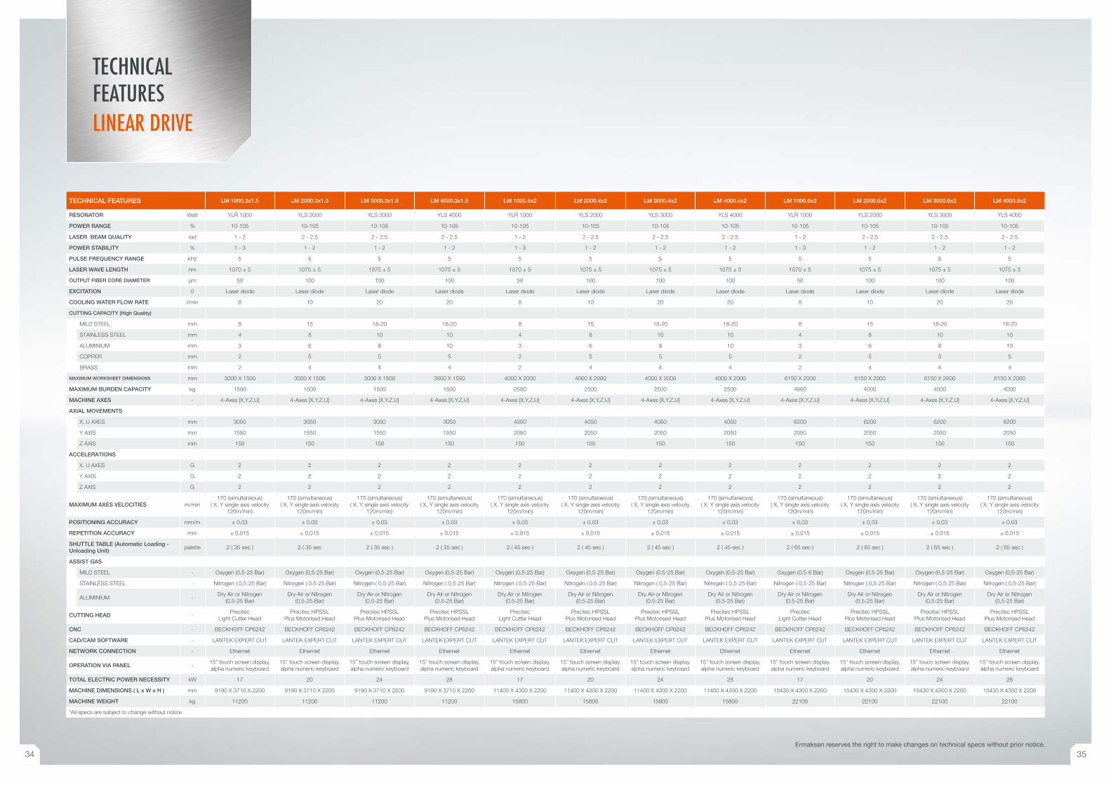
TECHNICAL FEATURES LM 1000.3x1.5 LM 2000.3x1.5 LM 3000.3x1.5 LM 4000.3x1.5 LM 1000.4x2 LM 2000.4x2 LM 3000.4x2 LM 4000.4x2 LM 1000.6x2 LM 2000.6x2 LM 3000.6x2 LM 4000.6x2
RESONATOR Watt YLR 1000 YLS 2000 YLS 3000 YLS 4000 YLR 1000 YLS 2000 YLS 3000 YLS 4000 YLR 1000 YLS 2000 YLS 3000 YLS 4000
POWER RANGE % 10-105 10-105 10-105 10-105 10-105 10-105 10-105 10-105 10-105 10-105 10-105 10-105
LASER BEAM QUALITY rad 1 - 2 2 - 2.5 2 - 2.5 2 - 2.5 1 - 2 2 - 2.5 2 - 2.5 2 - 2.5 1 - 2 2 - 2.5 2 - 2.5 2 - 2.5
POWER STABILITY % 1 - 3 1 - 2 1 - 2 1 - 2 1 - 3 1 - 2 1 - 2 1 - 2 1 - 3 1 - 2 1 - 2 1 - 2
PULSE FREQUENCY RANGE kHz 5 5 5 5 5 5 5 5 5 5 5 5
LASER WAVE LENGTH nm 1070 ± 5 1075 ± 5 1075 ± 5 1075 ± 5 1070 ± 5 1075 ± 5 1075 ± 5 1075 ± 5 1070 ± 5 1075 ± 5 1075 ± 5 1075 ± 5
OUTPUT FIBER CORE DIAMETER μm 50 100 100 100 50 100 100 100 50 100 100 100
EXCITATION 0 Laser diode Laser diode Laser diode Laser diode Laser diode Laser diode Laser diode Laser diode Laser diode Laser diode Laser diode Laser diode
COOLING WATER FLOW RATE l/min 8 10 20 20 8 10 20 20 8 10 20 20
CUTTING CAPACITY (High Quality)
MILD STEEL mm 8 15 18-20 18-20 8 15 18-20 18-20 8 15 18-20 18-20
STAINLESS STEEL mm 4 8 10 10 4 8 10 10 4 8 10 10
ALUMINIUM mm 3 6 8 10 3 6 8 10 3 6 8 10
COPPER mm 2 5 5 5 2 5 5 5 2 5 5 5
BRASS mm 2 4 4 4 2 4 4 4 2 4 4 4
MAXIMUM WORKSHEET DIMENSIONS mm 3000 X 1500 3000 X 1500 3000 X 1500 3000 X 1500 4000 X 2000 4000 X 2000 4000 X 2000 4000 X 2000 6150 X 2000 6150 X 2000 6150 X 2000 6150 X 2000
MAXIMUM BURDEN CAPACITY kg 1500 1500 1500 1500 2500 2500 2500 2500 4000 4000 4000 4000
MACHINE AXES - 4-Axes [X,Y,Z,U] 4-Axes [X,Y,Z,U] 4-Axes [X,Y,Z,U] 4-Axes [X,Y,Z,U] 4-Axes [X,Y,Z,U] 4-Axes [X,Y,Z,U] 4-Axes [X,Y,Z,U] 4-Axes [X,Y,Z,U] 4-Axes [X,Y,Z,U] 4-Axes [X,Y,Z,U] 4-Axes [X,Y,Z,U] 4-Axes [X,Y,Z,U]
AXIAL MOVEMENTS
X, U AXES mm 3050 3050 3050 3050 4050 4050 4050 4050 6200 6200 6200 6200
Y AXIS mm 1550 1550 1550 1550 2050 2050 2050 2050 2050 2050 2050 2050
Z AXIS mm 150 150 150 150 150 150 150 150 150 150 150 150
ACCELERATIONS
X, U AXES G 2 2 2 2 2 2 2 2 2 2 2 2
Y AXIS G 2 2 2 2 2 2 2 2 2 2 2 2
Z AXIS G 2 2 2 2 2 2 2 2 2 2 2 2
MAXIMUM AXES VELOCITIES m/min170 (simultaneous)
( X, Y single axis velocity 120m/min)
170 (simultaneous) ( X, Y single axis velocity
120m/min)
170 (simultaneous) ( X, Y single axis velocity
120m/min)
170 (simultaneous) ( X, Y single axis velocity
120m/min)
170 (simultaneous) ( X, Y single axis velocity
120m/min)
170 (simultaneous) ( X, Y single axis velocity
120m/min)
170 (simultaneous) ( X, Y single axis velocity
120m/min)
170 (simultaneous) ( X, Y single axis velocity
120m/min)
170 (simultaneous) ( X, Y single axis velocity
120m/min)
170 (simultaneous) ( X, Y single axis velocity
120m/min)
170 (simultaneous) ( X, Y single axis velocity
120m/min)
170 (simultaneous) ( X, Y single axis velocity
120m/min)
POSITIONING ACCURACY mm/m ± 0,03 ± 0,03 ± 0,03 ± 0,03 ± 0,03 ± 0,03 ± 0,03 ± 0,03 ± 0,03 ± 0,03 ± 0,03 ± 0,03
REPETITION ACCURACY mm ± 0,015 ± 0,015 ± 0,015 ± 0,015 ± 0,015 ± 0,015 ± 0,015 ± 0,015 ± 0,015 ± 0,015 ± 0,015 ± 0,015
SHUTTLE TABLE (Automatic Loading - Unloading Unit)
palette 2 ( 35 sec ) 2 ( 35 sec 2 ( 35 sec ) 2 ( 35 sec ) 2 ( 45 sec ) 2 ( 45 sec ) 2 ( 45 sec ) 2 ( 45 sec ) 2 ( 65 sec ) 2 ( 65 sec ) 2 ( 65 sec ) 2 ( 65 sec )
ASSIST GAS
MILD STEEL - Oxygen (0,5-25 Bar) Oxygen (0,5-25 Bar) Oxygen (0,5-25 Bar) Oxygen (0,5-25 Bar) Oxygen (0,5-25 Bar) Oxygen (0,5-25 Bar) Oxygen (0,5-25 Bar) Oxygen (0,5-25 Bar) Oxygen (0,5-6 Bar) Oxygen (0,5-25 Bar) Oxygen (0,5-25 Bar) Oxygen (0,5-25 Bar)
STAINLESS STEEL - Nitrogen ( 0,5-25 Bar) Nitrogen ( 0,5-25 Bar) Nitrogen ( 0,5-25 Bar) Nitrogen ( 0,5-25 Bar) Nitrogen ( 0,5-25 Bar) Nitrogen ( 0,5-25 Bar) Nitrogen ( 0,5-25 Bar) Nitrogen ( 0,5-25 Bar) Nitrogen ( 0,5-25 Bar) Nitrogen ( 0,5-25 Bar) Nitrogen ( 0,5-25 Bar) Nitrogen ( 0,5-25 Bar)
ALUMINIUM -Dry Air or Nitrogen
(0,5-25 Bar)Dry Air or Nitrogen
(0,5-25 Bar)Dry Air or Nitrogen
(0,5-25 Bar)Dry Air or Nitrogen
(0,5-25 Bar)Dry Air or Nitrogen
(0,5-25 Bar)Dry Air or Nitrogen
(0,5-25 Bar)Dry Air or Nitrogen
(0,5-25 Bar)Dry Air or Nitrogen
(0,5-25 Bar)Dry Air or Nitrogen
(0,5-25 Bar)Dry Air or Nitrogen
(0,5-25 Bar)Dry Air or Nitrogen
(0,5-25 Bar)Dry Air or Nitrogen
(0,5-25 Bar)
CUTTING HEAD -Precitec
Light Cutter HeadPrecitec HPSSL
Plus Motorised HeadPrecitec HPSSL
Plus Motorised HeadPrecitec HPSSL
Plus Motorised HeadPrecitec
Light Cutter HeadPrecitec HPSSL
Plus Motorised HeadPrecitec HPSSL
Plus Motorised HeadPrecitec HPSSL
Plus Motorised HeadPrecitec
Light Cutter HeadPrecitec HPSSL
Plus Motorised HeadPrecitec HPSSL
Plus Motorised HeadPrecitec HPSSL
Plus Motorised Head
CNC - BECKHOFF CP6242 BECKHOFF CP6242 BECKHOFF CP6242 BECKHOFF CP6242 BECKHOFF CP6242 BECKHOFF CP6242 BECKHOFF CP6242 BECKHOFF CP6242 BECKHOFF CP6242 BECKHOFF CP6242 BECKHOFF CP6242 BECKHOFF CP6242
CAD/CAM SOFTWARE - LANTEK EXPERT CUT LANTEK EXPERT CUT LANTEK EXPERT CUT LANTEK EXPERT CUT LANTEK EXPERT CUT LANTEK EXPERT CUT LANTEK EXPERT CUT LANTEK EXPERT CUT LANTEK EXPERT CUT LANTEK EXPERT CUT LANTEK EXPERT CUT LANTEK EXPERT CUT
NETWORK CONNECTION - Ethernet Ethernet Ethernet Ethernet Ethernet Ethernet Ethernet Ethernet Ethernet Ethernet Ethernet Ethernet
OPERATION VIA PANEL -15” touch screen display, alpha numeric keyboard
15” touch screen display, alpha numeric keyboard
15” touch screen display, alpha numeric keyboard
15” touch screen display, alpha numeric keyboard
15” touch screen display, alpha numeric keyboard
15” touch screen display, alpha numeric keyboard
15” touch screen display, alpha numeric keyboard
15” touch screen display, alpha numeric keyboard
15” touch screen display, alpha numeric keyboard
15” touch screen display, alpha numeric keyboard
15” touch screen display, alpha numeric keyboard
15” touch screen display, alpha numeric keyboard
TOTAL ELECTRIC POWER NECESSITY kW 17 20 24 28 17 20 24 28 17 20 24 28
MACHINE DIMENSIONS ( L x W x H ) mm 9190 X 3710 X 2200 9190 X 3710 X 2200 9190 X 3710 X 2200 9190 X 3710 X 2200 11400 X 4300 X 2200 11400 X 4300 X 2200 11400 X 4300 X 2200 11400 X 4300 X 2200 15430 X 4300 X 2200 15430 X 4300 X 2200 15430 X 4300 X 2200 15430 X 4300 X 2200
MACHINE WEIGHT kg 11200 11200 11200 11200 15800 15800 15800 15800 22100 22100 22100 22100
*All specs are subject to change without notice
TECHNICAL FEATURESLINEAR DRIVE
Ermaksan reserves the right to make changes on technical specs without prior notice.
34 35
Fibe
rmak
- E
NG
© A
ll rig
hts
rese
rved
. 07/
2014
/ermaksan.com.tr /ermaksanmachine /ErmaksanTV
Organize Sanayi Bölgesi, Lacivert Cad. No:6 Nilüfer, Bursa / TÜRKİYET: +90 224 294 75 00 (pbx) F: +90 224 294 75 44www.ermaksan.com.tr | [email protected]
M E T A L F A B R I C A T I N G M A C H I N E R Y
innovative technologies.
Innovative Technologies | www.ermaksan.com.tr | Laser Series