Embed Size (px)
Citation preview

FCI and VORTAB®:
Proven Partners
for Accurate
FCI AND V
ORTAB
®Gas Mass Flow
Measurement.
Fluid Components Intl and VORTAB® Corporation have formedan exclusive partnership to provide a lower cost, reliable, high per-formance solution for accurate mass flowmetering in gas applica-tions. The new FCI/VORTAB Flowmetering System combines FCI'sfield-proven thermal gas mass flowmeters with VORTAB's patentedlow pressure loss flow conditioners.
FCI Flowmeters Since 1964, FCI has provided highperformance thermal flow sensing for tough applications in theprocessing, nuclear and fossil fuel power, wastewater treatment andaerospace industries. All FCI Flowmeters feature FCI’s ThermalDispersion operating principle providing stable performance,high reliability and low flow sensitivity. FCI’s no-moving parts designensures dependable, virtually maintenance-free performance inharsh, dirty and explosive gas mass flowmetering applications.Microprocessor-based electronics add increased flexibility to FCI’sMass Flowmeters permitting user-friendly operations and mainte-nance, easy in-field adjustment of zero, span and display units, andbuilt-in testing and self-diagnostics.
VORTAB® Flow Conditioners VORTAB Flow Conditionersprovide a low pressure loss solution to flow profile irregularitiesproduced by elbows, valves, blowers, compressors, and otherdisruptions that commonly occur in pipe and duct runs. By elimi-nating flow profile irregularities and temperature or media strati-fication, they ensure accurate, repeatable gas flow measurementand are the efficient alternative to long lengths of straight pipingor ducting upstream from a flowmeter. VORTAB Flow Conditionersprovide the most thorough conditioning, in a shorter distance,with a fraction of the pressure loss of any other flow straighteneror conditioner available today.
Performance from Teamwork By teaming FCI’s provenThermal Dispersion Mass Flowmetering experience and productswith VORTAB Flow Conditioners, FCI now provides unequalled gasmass flowmetering performance in applications previously consid-ered too difficult or impractical to meter.
The VORTAB Flow Conditioner, located just three (3) diame-ters upstream of the FCI Flowmeter installation, virtually eliminatesgas flow swirl and velocity profile distortions as well as tempera-ture and media stratification produced by process equipment ob-structions and/or inadequate straight run of pipe and ducting. Thisresults in tremendous flowmetering accuracy and repeatabilityimprovements. The FCI/VORTAB team provides the ideal solution forindustry’s toughest, most critical gas mass flowmetering applications.
Proven Flow Conditioning Technology VORTAB FlowConditioners uniquely combine proven swirl removal technologywith the patented VORTAB mixing process to achieve the most thor-ough and efficient flow conditioning available. Each of the threeavailable flow conditioner configurations consists of a short sectionof swirl reduction tabs combined with three (3) arrays of VORTABprofile conditioning tabs. This design produces: � rapid cross-stream mixing � minimizes swirl and velocity profile distortions� produces flow profile repeatability across a broad flow range.
Equally important, VORTAB Flow Conditioners feature apatented low pressure loss design. Non-recoverable pressure losscan reduce maximum flow capability in process lines, creating processinefficiencies and requiring greater energy expenditures to moveprocess gases. Perforated plates, tube bundles, screens and other flowconditioning technologies produce a much greater pressure lossthan VORTAB Flow Conditioners and, unlike VORTAB Flow Condi-tioners, are subject to clogging or fouling in industrial applications.
The patented VORTAB® technology provides unmatchedperformance with little pressure loss and swirl-free, condi-tioned flow profile. It is the ideal partner for FCI’s low pres-sure loss, centerline mounted single-point and equal areamulti-point sensor technology.
Economic, Flexible Installation To meet industry’s de-mand for installation flexibility, ease and economy, the FCI/VORTAB
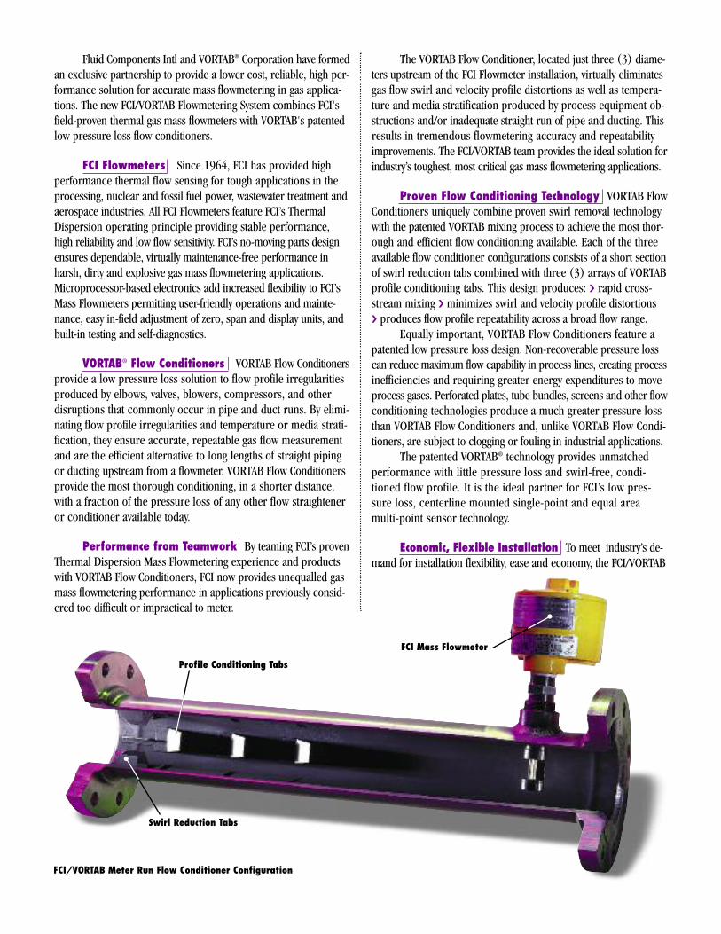
Profile Conditioning Tabs
Swirl Reduction Tabs
FCI/VORTAB Meter Run Flow Conditioner Configuration
FCI Mass Flowmeter
Flow Conditioning System is available in three configurations (seethe outline dimension drawings on the back page):
1.) Meter Run Configuration. The Meter Run Configur-ation (VMR) offers a complete, simple pipe section replacementfor new and existing piping systems. The VORTAB Flow Conditioneris precisely located three (3) diameters upstream of the FCI flow-meter port in a seven (7) (eight (8) with 2” pipe) diameters longbuilt-in pipe section: A variety of end connections and pipe sizesfrom 2 to 12 inches (51 to 305 mm) are available.
2.) Insertion Sleeve Configuration. The Insertion SleeveConfiguration (VIS) allows for direct mounting in existing or speciallysized pipe sections. The swirl and conditioning tabs are connectedto a mounting sleeve that slides into the process piping. Attachmentmethods include welded-in-place or captured flange designs.
3.) Field Kit Configuration. The Field Kit Configuration(VFK) is designed for use in very large ducts and piping, squareducts and irregular shaped installations. The kit comes completewith separate profile conditioning and swirl reduction tabs thathave been sized for the specific application. Complete instructionsare included to permit easy, permanent field installation.
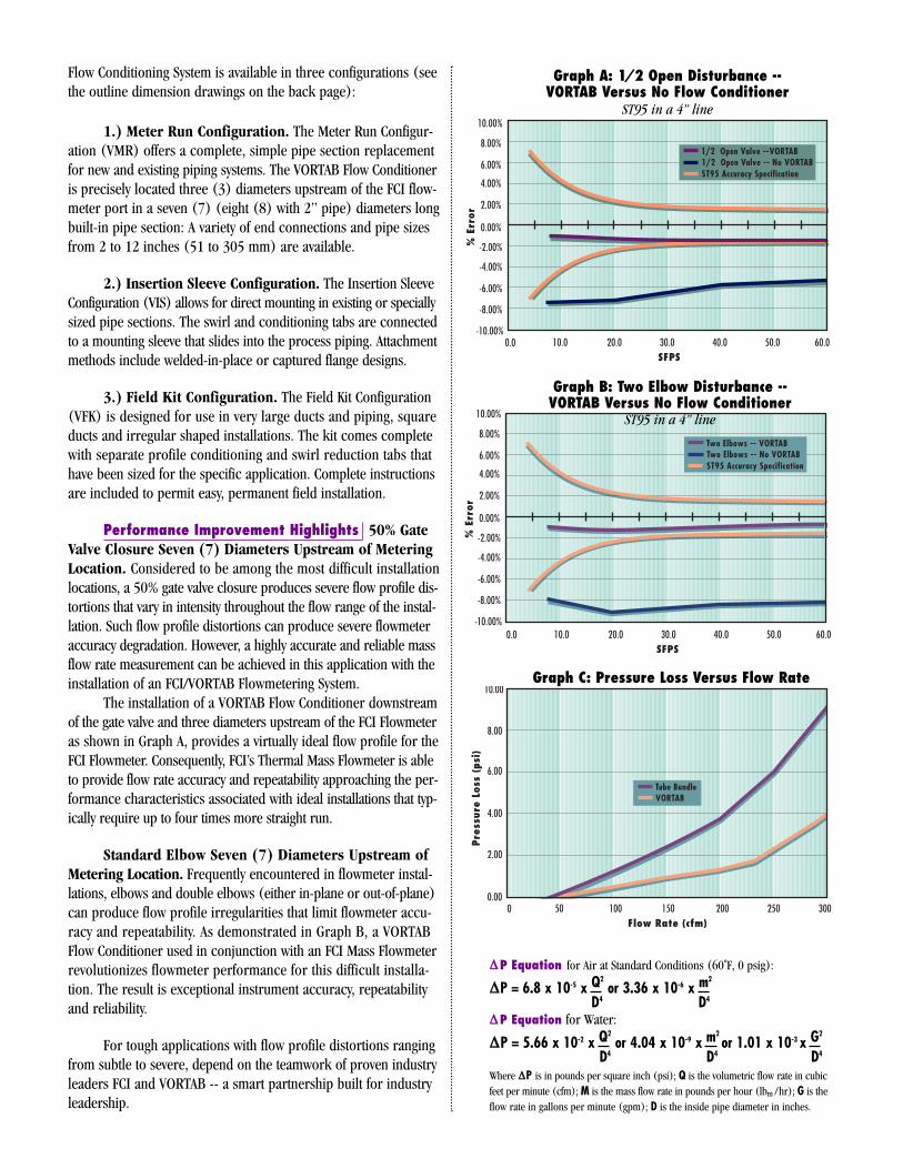
Performance Improvement Highlights 50% GateValve Closure Seven (7) Diameters Upstream of MeteringLocation. Considered to be among the most difficult installationlocations, a 50% gate valve closure produces severe flow profile dis-tortions that vary in intensity throughout the flow range of the instal-lation. Such flow profile distortions can produce severe flowmeteraccuracy degradation. However, a highly accurate and reliable massflow rate measurement can be achieved in this application with theinstallation of an FCI/VORTAB Flowmetering System.
The installation of a VORTAB Flow Conditioner downstreamof the gate valve and three diameters upstream of the FCI Flowmeteras shown in Graph A, provides a virtually ideal flow profile for theFCI Flowmeter. Consequently, FCI’s Thermal Mass Flowmeter is ableto provide flow rate accuracy and repeatability approaching the per-formance characteristics associated with ideal installations that typ-ically require up to four times more straight run.
Standard Elbow Seven (7) Diameters Upstream ofMetering Location. Frequently encountered in flowmeter instal-lations, elbows and double elbows (either in-plane or out-of-plane)can produce flow profile irregularities that limit flowmeter accu-racy and repeatability. As demonstrated in Graph B, a VORTABFlow Conditioner used in conjunction with an FCI Mass Flowmeterrevolutionizes flowmeter performance for this difficult installa-tion. The result is exceptional instrument accuracy, repeatabilityand reliability.
For tough applications with flow profile distortions rangingfrom subtle to severe, depend on the teamwork of proven industryleaders FCI and VORTAB -- a smart partnership built for industryleadership.
1/2 Open Valve --VORTAB
ST95 Accuracy Specification1/2 Open Valve -- No VORTAB
0.0 10.0 20.0 30.0 40.0 50.0 60.0-10.00%
-8.00%
-6.00%
-4.00%
-2.00%
0.00%
2.00%
4.00%
6.00%
8.00%
10.00%
%Er
ror
SFPS
Graph A: 1/2 Open Disturbance --VORTAB Versus No Flow Conditioner
ST95 in a 4” line
Graph B: Two Elbow Disturbance --VORTAB Versus No Flow Conditioner
ST95 in a 4” line
Graph C: Pressure Loss Versus Flow Rate
D4 D4
D4 D4 D4
∆∆P Equation for Air at Standard Conditions (60˚F, 0 psig):
∆∆P = 6.8 x 10⁻⁵ x Q2
or 3.36 x 10⁻⁶ x m2
∆∆P Equation for Water:
∆∆P = 5.66 x 10⁻² x Q2
or 4.04 x 10⁻⁹ x m2or 1.01 x 10⁻³ x G
2
Where ∆∆P is in pounds per square inch (psi); Q is the volumetric flow rate in cubicfeet per minute (cfm); M is the mass flow rate in pounds per hour (lbm /hr); G is theflow rate in gallons per minute (gpm); D is the inside pipe diameter in inches.
Guaranteed Performance. FCI guarantees performance ofits entire product line -- including the FCI/VORTAB FlowmeteringSystem, mass flowmeters, flow switch/monitors, and liquid level andinterface controllers -- in accepted applications or your money back.
1-Year Warranty. FCI warranties its products against faulty
materials or workmanship for one full year from the date of delivery tothe buyer. (Ask for a copy of our complete warranty.)
Customer Service. FCI commits itself to providing prompt,24 hour customer service including expedited field service and repairsupport, and toll-free factory service.
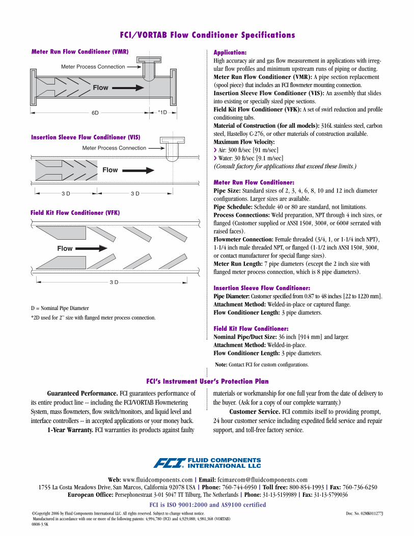
D = Nominal Pipe Diameter
*2D used for 2” size with flanged meter process connection.
FCI’s Instrument User’s Protection Plan
FCI/VORTAB Flow Conditioner Specifications
Application:High accuracy air and gas flow measurement in applications with irreg-ular flow profiles and minimum upstream runs of piping or ducting.Meter Run Flow Conditioner (VMR): A pipe section replacement(spool piece) that includes an FCI flowmeter mounting connection.Insertion Sleeve Flow Conditioner (VIS): An assembly that slidesinto existing or specially sized pipe sections.Field Kit Flow Conditioner (VFK): A set of swirl reduction and profileconditioning tabs.Material of Construction (for all models): 316L stainless steel, carbonsteel, Hastelloy C-276, or other materials of construction available.Maximum Flow Velocity: � Air: 300 ft/sec [91 m/sec]� Water: 30 ft/sec [9.1 m/sec](Consult factory for applications that exceed these limits.)
Meter Run Flow Conditioner:Pipe Size: Standard sizes of 2, 3, 4, 6, 8, 10 and 12 inch diameterconfigurations. Larger sizes are available.Pipe Schedule: Schedule 40 or 80 are standard, not limitations.Process Connections: Weld preparation, NPT through 4 inch sizes, orflanged (Customer supplied or ANSI 150#, 300#, or 600# serrated withraised faces).Flowmeter Connection: Female threaded (3/4, 1, or 1-1/4 inch NPT),1-1/4 inch male threaded NPT, or flanged (1-1/2 inch ANSI 150#, 300#,or contact manufacturer for special flange sizes).Meter Run Length: 7 pipe diameters (except the 2 inch size withflanged meter process connection, which is 8 pipe diameters).
Insertion Sleeve Flow Conditioner:Pipe Diameter: Customer specified from 0.87 to 48 inches [22 to 1220 mm].Attachment Method: Welded-in-place or captured flange.Flow Conditioner Length: 3 pipe diameters.
Field Kit Flow Conditioner:Nominal Pipe/Duct Size: 36 inch [914 mm] and larger.Attachment Method: Welded-in-place.Flow Conditioner Length: 3 pipe diameters.
©Copyright 2006 by Fluid Components International LLC. All rights reserved. Subject to change without notice. Doc. No. 02MK011277JManufactured in accordance with one or more of the following patents: 4,994,780 (FCI) and 4,929,088; 4,981,368 (VORTAB)0808-3.5K
Note: Contact FCI for custom configurations.
Meter Run Flow Conditioner (VMR)
Insertion Sleeve Flow Conditioner (VIS)
Field Kit Flow Conditioner (VFK)
Web: www.fluidcomponents.com | Email: [email protected] La Costa Meadows Drive, San Marcos, California 92078 USA | Phone: 760-744-6950 | Toll free: 800-854-1993 | Fax: 760-736-6250
European Office: Persephonestraat 3-01 5047 TT Tilburg, The Netherlands | Phone: 31-13-5159989 | Fax: 31-13-5799036FCI is ISO 9001:2000 and AS9100 certified

Vortab® Flow ConditionersTechnical Note
Transitional Flow Effects on Flow Meter Measuring Accuracy
Vortab Flow Conditioning Eliminates Transitional Flow EffectsVortab flow conditioners are widely recognized and applied in flow metering applications to correct the unpredictable effects of flow profile shifts caused by limited straight-run, upstream pipe geometry changes (e.g. damper positioning) and load changes. These unpredictable flow profile variations are neutralized as they pass through the Vortab flow conditioner to present a consistent, predictable outlet flow profile to the flow meter that results in accurate and repeatable flow measurements. Additionally, Vortab flow conditioners also efficiently neutralize transitional flow effects.
To appreciate the value of Vortab flow conditioning in applications with naturally occurring flow profile variations, it is first necessary to understand how flow profiles can change. Engineers specifying flow metering technologies are very aware that flow profile variations and unpredictability will directly result in measurement inaccuracy. Engineers further understand that flow profiles are a function of pipe geometry, Reynolds number (Re), internal pipe roughness and rate of change.
It is widely known that many diameters of uninterrupted straight pipe runs are necessary to produce the fully developed turbulent flow profiles preferred by many measuring technologies. However, in applications with low flow detection and wide turndown what is often overlooked is that the flow profile also “transitions” dramatically and without correction can result in tremendous flow metering inaccuracies over a portion of a critical measuring range. Consider the difference between laminar and turbulent flow conditions. Laminar flow occurs at low velocities where the Re number is below 2000. Turbulent flow typically occurs above Re of 4000. When flow occurs between the 2000-4000 Re region it is commonly referred to as being in the “transitional” flow range. However, depending on the direction, either increasing or decreasing flow, and the rate of change, transitional flow can continue up to 7000 Re.
As the Reynolds number and velocity increase from 2000 Re up to 4000 Re, the relationship between the average velocity V (avg)
and the centerline velocity V (max) dramatically increases from 50% up to nearly 80%. Accordingly, the velocity profile from the centerline to the pipe wall is also changing at a dramatic rate. Insertion type, point flow measuring instruments will be susceptible to profile changes during this transitional flow range to large varying degrees. Virtually all point insertion type flow sensors are susceptible, regardless of whether they are centerline positioned or have variable insertion depths. These types of profile effects are generally more acute in smaller line sizes.
Figure 1. Laminar vs. turbulent flow profiles
The laminar profile takes on a parabolic shape where the relationship between the average velocity and centerline velocity is quite dramatic when compared to the turbulent flow profile. Source: Richard Miller, Flow Measurement Engineering Handbook ; Vortab profile added by FCI

Relationship: Average V (avg) and Maximum V (max)In Figure 2, the centerline relationship between V (max) and V (avg) can transition from 50% to in excess of 80% as flow rates change from laminar to turbulent.
Vortab flow conditioners eliminate the unpredictability and unwanted effects as transitional flow profiles transition by producing a flattened, highly repeatable flow profile that remains essentially unaltered while velocities and associated Re numbers move from laminar through transitional to turbulent flow.
With a Vortab flow conditioner the relationship between V (avg) and V (max) is maintained and a nearly constant flow profile
is maintained downstream. When a Fluid Components International (FCI) flow meter is paired with a Vortab flow conditioner, a stable and consistent flow profile, independent of direction or rate of change, is produced upstream of the flow meter, resulting in highly accurate and repeatable meter performance. In all wide turndown applications, FCI can easily determine whether transitional flows will occur within a specified metering range. However, it is more difficult to predict whether transitional flow effects will be broad or narrow, or specifically where they will occur over a critical portion of the desired metering range. Figure 3 shows an uncorrected flow profile effect and a Vortab corrected flow profile.
FCI’s thermal dispersion type devices feature wide turndown capability and low flow sensitivity. As a result, it is very common for engineers to specify large turndown requirements that include laminar, transitional and turbulent profiles. Fortunately, it is relatively easy for FCI to calibrate for both laminar flow rates and turbulent flow rates during the same instrument calibration — these profile variations can be reproduced during laboratory calibration. However, whenever there are both laminar and turbulent profiles, there is always a transitional flow profile that contains tremendous variations. FCI flow meters are centerline mounted to consistently utilize the relationship between maximum velocity V (max), and average velocity V (avg) as centerline flows are the most predictable. When FCI flow meters are installed with Vortab flow conditioners, transitional errors are eliminated, which provides optimum accuracy through the entire metering range.
Figure 2. Ratio of average to maximum (centerline) velocity for smooth and rough pipe Source: Richard Miller, Flow Measurement Engineering Handbook
Figure 3. FCI ST Series Flow Meter in Argon
FCI Model ST75V (left, inset)
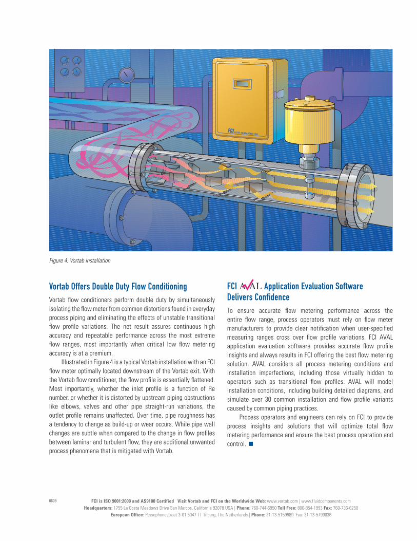
Vortab Offers Double Duty Flow ConditioningVortab flow conditioners perform double duty by simultaneously isolating the flow meter from common distortions found in everyday process piping and eliminating the effects of unstable transitional flow profile variations. The net result assures continuous high accuracy and repeatable performance across the most extreme flow ranges, most importantly when critical low flow metering accuracy is at a premium.
Illustrated in Figure 4 is a typical Vortab installation with an FCI flow meter optimally located downstream of the Vortab exit. With the Vortab flow conditioner, the flow profile is essentially flattened. Most importantly, whether the inlet profile is a function of Re number, or whether it is distorted by upstream piping obstructions like elbows, valves and other pipe straight-run variations, the outlet profile remains unaffected. Over time, pipe roughness has a tendency to change as build-up or wear occurs. While pipe wall changes are subtle when compared to the change in flow profiles between laminar and turbulent flow, they are additional unwanted process phenomena that is mitigated with Vortab.
FCI Application Evaluation Software Delivers Confidence To ensure accurate flow metering performance across the entire flow range, process operators must rely on flow meter manufacturers to provide clear notification when user-specified measuring ranges cross over flow profile variations. FCI AVAL application evaluation software provides accurate flow profile insights and always results in FCI offering the best flow metering solution. AVAL considers all process metering conditions and installation imperfections, including those virtually hidden to operators such as transitional flow profiles. AVAL will model installation conditions, including building detailed diagrams, and simulate over 30 common installation and flow profile variants caused by common piping practices.
Process operators and engineers can rely on FCI to provide process insights and solutions that will optimize total flow metering performance and ensure the best process operation and control. g
FCI is ISO 9001:2000 and AS9100 Certified Visit Vortab and FCI on the Worldwide Web: www.vortab.com | www.fluidcomponents.com Headquarters: 1755 La Costa Meadows Drive San Marcos, California 92078 USA | Phone: 760-744-6950 Toll Free: 800-854-1993 Fax: 760-736-6250
European Office: Persephonestraat 3-01 5047 TT Tilburg, The Netherlands | Phone: 31-13-5159989 Fax: 31-13-5799036
0809
Figure 4. Vortab installation