Embed Size (px)
Citation preview

FCC Caution
FCC Part 15.19 Caution:
• This device complies with Part 15 of the FCC Rules. Operation is subject to
the following two conditions:
◦ this device may not cause harmful interference and
◦ this device must accept any interference received, including interference
that may cause undesired operation
• This device and its antenna(s) must not be co-located or operating in
conjunction with any other antenna or transmitter.
• Changes or modifications to this unit not expressly approved by the party
responsible for compliance could void the user authority to operate the
equipment.
IMPORTANT NOTE:
FCC Radiation Exposure Statement:
This equipment complies with FCC radiation exposure limits set forth for an
uncontrolled environment. This equipment should be installed and operated with
minimum distance 20cm between the radiator & your body.
This transmitter must not be co-located or operating in conjunction with any other
antenna or transmitter.
The antennas used for this transmitter must be installed to provide a separation
distance of at least 20 cm from all persons and must not be co-located or operating
in conjunction with any other antenna or transmitter.
FCC Statement in User’s Manual (for calss B)
FCC Section 15.105
“Federal Communications Commission (FCC) Statement”
This equipment has been tested and found to comply with the limits for a lass B
digital device, pursuant to Part 15 of the FCC Rules. These limits are designed to
provide reasonable protection against harmful interference in a residential
installation. This equipment generates uses and can radiate radio frequency energy
and, if not installed and used in accordance with the instructions, may cause harmful
interference to radio communications. However, there is no guarantee that
interference will not occur in a particular installation. If this equipment does cause
harmful interference to radio or television reception, which can be determined by
turning the equipment off and on, the user is encouraged to try to correct the
interference by one or more of the following measures:
• Reorient or relocate the receiving antenna.
• Increase the separation between the equipment and receiver.
• Connect the equipment into an outlet on a circuit different from that to which
the receiver is connected.
• Consult the dealer or an experienced radio/TV technician for help.
CE Statement of Conformity
Our product has been tested in typical configuration by Ecom Sertech Corp and was
found to comply with the essential requirement of “Council Directive on the
Approximation of the Laws of the Member States relating to Electromagnetic
Compatibility” (89/336/EEC; 92/31/EEC; 93/68/EEC)
1 Introduction Product Appearance
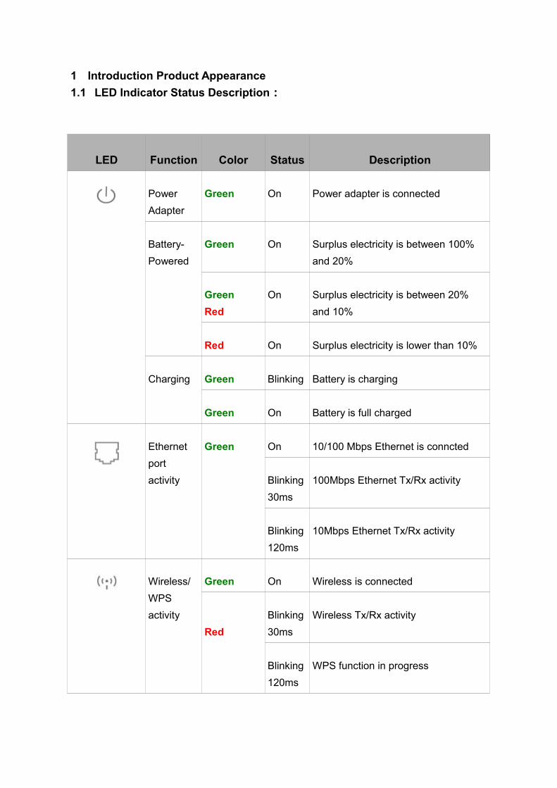
1.1 LED Indicator Status Description:
LED Function Color Status Description
Power
Adapter
Green On Power adapter is connected
Battery-
Powered
Green On Surplus electricity is between 100%
and 20%
Green
Red
On Surplus electricity is between 20%
and 10%
Red On Surplus electricity is lower than 10%
Charging Green Blinking Battery is charging
Green On Battery is full charged
Ethernet
port
activity
Green On 10/100 Mbps Ethernet is conncted
Blinking
30ms
100Mbps Ethernet Tx/Rx activity
Blinking
120ms
10Mbps Ethernet Tx/Rx activity
Wireless/
WPS
activity
Green On Wireless is connected
Red
Blinking
30ms
Wireless Tx/Rx activity
Blinking
120ms
WPS function in progress
2 System and Network Setup
The BRB73n is a built-in 3.5G mobile router,it allows user to share the wireless
network on a moving vehicle and be an alternative or backup to fixed broadband as
well.
To begin with BRB73n , you must have the following minimum system requirements.
If your system can’t correspond to the following requirements, you might get some
unknown troubles on your system.
• Internet Account for XDSL/Cable Modem/3.5G
• One Ethernet (10/100mbps) network interface card or wireless dongle
• TCP/IP and at least one web browser software installed (E.g.: Internet
Explorer、Firefox、Safari、Chrome latest version )• 802.11b、g、n wireless adapter for wireless mobile cliens
• Recommended OS: WinXP, Visata or Win7 / Linux
2.1 Build Network Connection
Administrator can manage the settings for WAN, LAN, Wireless Network, NTP,
password, VPN, Firewall, etc.
Please confirm the network environment or the purpose before setting this product.
2.2 Connecting BRB73n
• Prepare the followings before the connection:
• PC or Notebook for setup
• Wireless connection (Ethernet port default is for internet)• Make sure you are under “Router Mode”.
• Turn on your Computer.
• Connect BRB73n to xDSL/ Cable modem with the Ethernet cable, or put in
3.5G SIM card
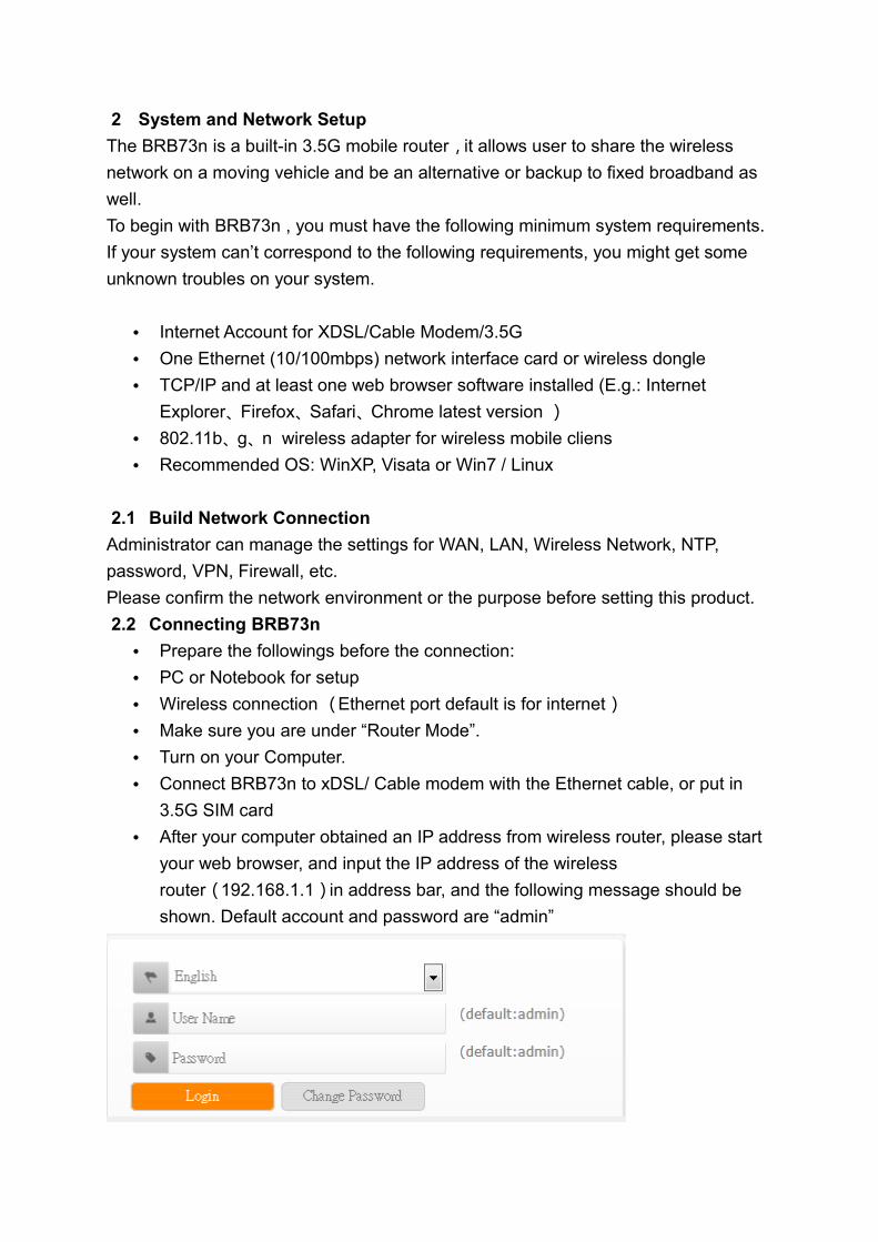
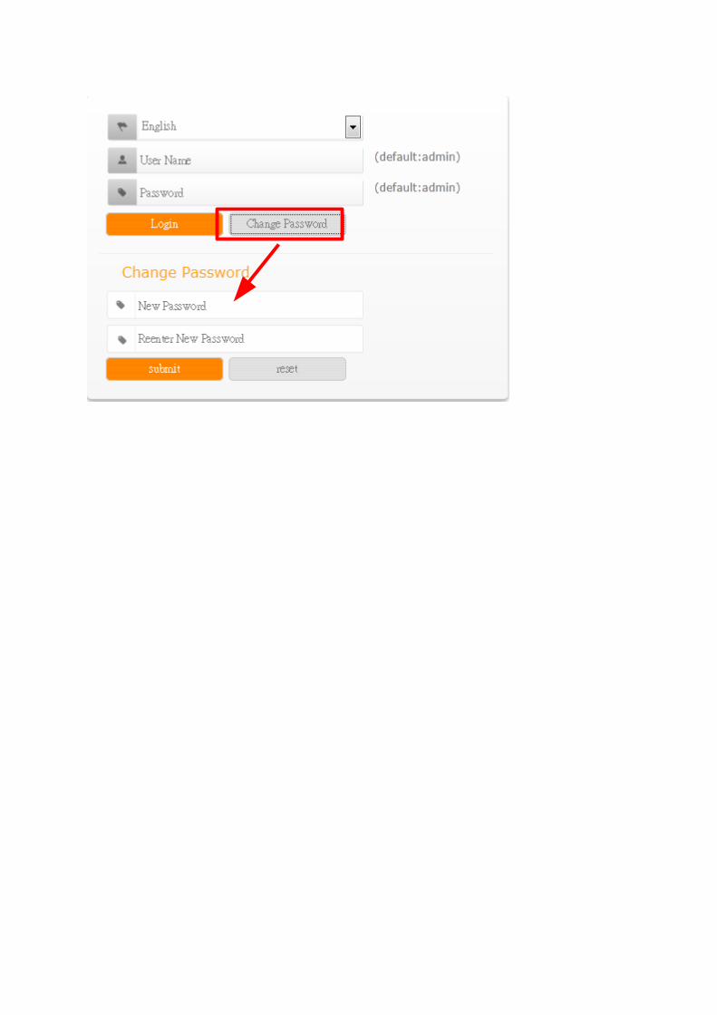
• After your computer obtained an IP address from wireless router, please start
your web browser, and input the IP address of the wireless
router(192.168.1.1)in address bar, and the following message should be
shown. Default account and password are “admin”

• Users can set or change user name and password used for accessing the
web management interface in this section.
• Input User Name and New Password, then input Confirm Password again.
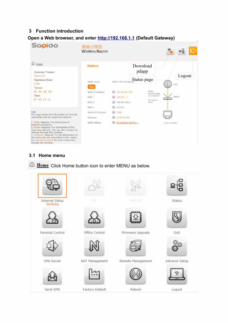
3 Function introduction
Open a Web browser, and enter http://192.168.1.1 (Default Gateway)
3.1 Home menu
Click Home button icon to enter MENU as below.
Status pageLogout
Download pdapp
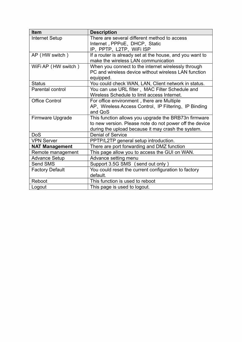
Item DescriptionInternet Setup There are several different method to access
Internet,PPPoE、DHCP、Static IP、PPTP、L2TP、WiFi ISP
AP(HW switch) If a router is already set at the house, and you want to make the wireless LAN communication
WiFi AP(HW switch) When you connect to the internet wirelessly through PC and wireless device without wireless LAN function equipped.
Status You could check WAN, LAN, Client network in status.Parental control You can use URL filter 、MAC Filter Schedule and
Wireless Schedule to limit access Internet.Office Control For office environment,there are Multiple
AP、Wireless Access Control、IP Filtering、IP Binding and QoS
Firmware Upgrade This function allows you upgrade the BRB73n firmware to new version. Please note do not power off the device during the upload because it may crash the system.
DoS Denial of ServiceVPN Server PPTP/L2TP general setup introduction.NAT Management There are port forwarding and DMZ functionRemote management This page allow you to access the GUI on WAN.Advance Setup Advance setting menuSend SMS Support 3.5G SMS (send out only)Factory Default You could reset the current configuration to factory
default.Reboot This function is used to rebootLogout This page is used to logout.
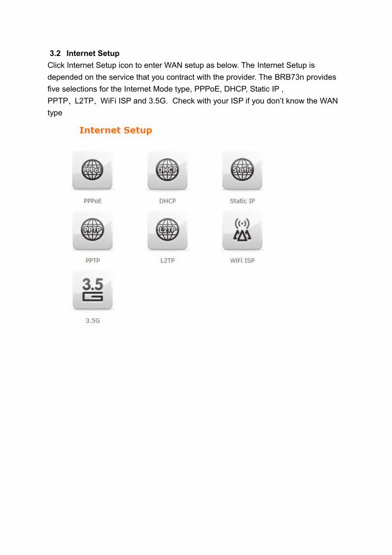
3.2 Internet Setup
Click Internet Setup icon to enter WAN setup as below. The Internet Setup is
depended on the service that you contract with the provider. The BRB73n provides
five selections for the Internet Mode type, PPPoE, DHCP, Static IP ,
PPTP、L2TP、WiFi ISP and 3.5G. Check with your ISP if you don’t know the WAN
type
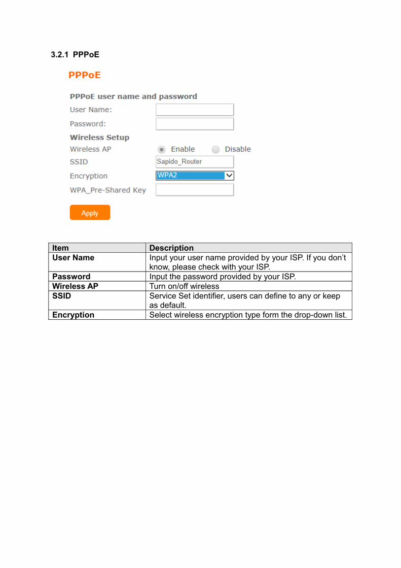
3.2.1 PPPoE
Item DescriptionUser Name Input your user name provided by your ISP. If you don’t
know, please check with your ISP. Password Input the password provided by your ISP.Wireless AP Turn on/off wirelessSSID Service Set identifier, users can define to any or keep
as default.Encryption Select wireless encryption type form the drop-down list.
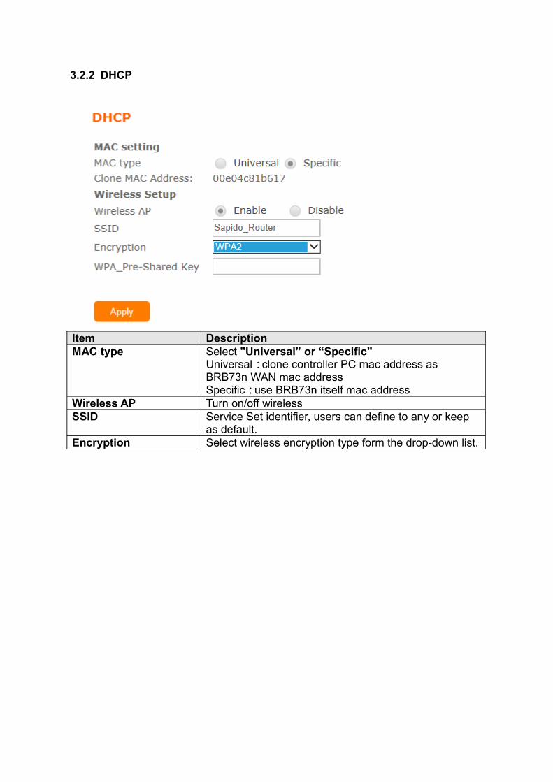
3.2.2 DHCP
Item DescriptionMAC type Select "Universal” or “Specific"
Universal:clone controller PC mac address as BRB73n WAN mac addressSpecific:use BRB73n itself mac address
Wireless AP Turn on/off wirelessSSID Service Set identifier, users can define to any or keep
as default.Encryption Select wireless encryption type form the drop-down list.
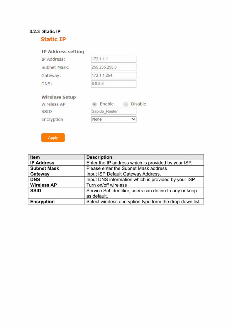
3.2.3 Static IP
Item DescriptionIP Address Enter the IP address which is provided by your ISP. Subnet Mask Please enter the Subnet Mask addressGateway Input ISP Default Gateway Address.DNS Input DNS information which is provided by your ISPWireless AP Turn on/off wirelessSSID Service Set identifier, users can define to any or keep
as default.Encryption Select wireless encryption type form the drop-down list.
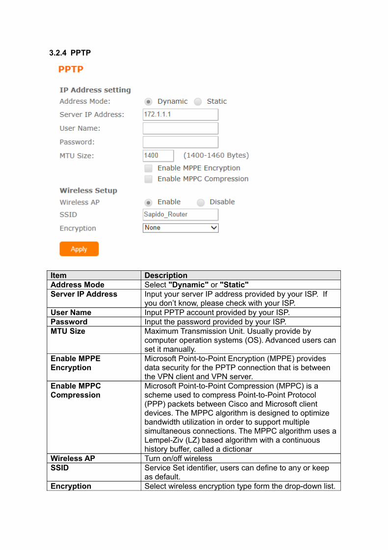
3.2.4 PPTP
Item DescriptionAddress Mode Select "Dynamic" or "Static"Server IP Address Input your server IP address provided by your ISP. If
you don’t know, please check with your ISP.User Name Input PPTP account provided by your ISP. Password Input the password provided by your ISP.MTU Size Maximum Transmission Unit. Usually provide by
computer operation systems (OS). Advanced users can set it manually.
Enable MPPE Encryption
Microsoft Point-to-Point Encryption (MPPE) provides data security for the PPTP connection that is between the VPN client and VPN server.
Enable MPPC Compression
Microsoft Point-to-Point Compression (MPPC) is a scheme used to compress Point-to-Point Protocol (PPP) packets between Cisco and Microsoft client devices. The MPPC algorithm is designed to optimize bandwidth utilization in order to support multiple simultaneous connections. The MPPC algorithm uses a Lempel-Ziv (LZ) based algorithm with a continuous history buffer, called a dictionar
Wireless AP Turn on/off wirelessSSID Service Set identifier, users can define to any or keep
as default.Encryption Select wireless encryption type form the drop-down list.
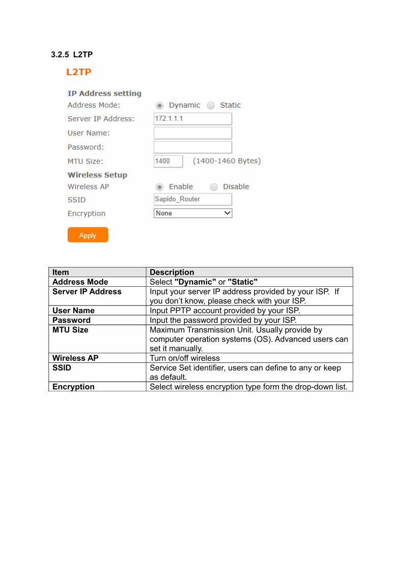
3.2.5 L2TP
Item DescriptionAddress Mode Select "Dynamic" or "Static"Server IP Address Input your server IP address provided by your ISP. If
you don’t know, please check with your ISP.User Name Input PPTP account provided by your ISP. Password Input the password provided by your ISP.MTU Size Maximum Transmission Unit. Usually provide by
computer operation systems (OS). Advanced users can set it manually.
Wireless AP Turn on/off wirelessSSID Service Set identifier, users can define to any or keep
as default.Encryption Select wireless encryption type form the drop-down list.
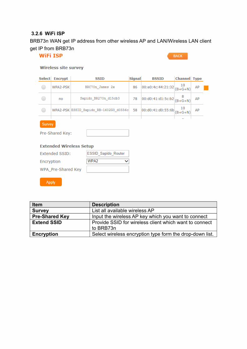
3.2.6 WiFi ISP
BRB73n WAN get IP address from other wireless AP and LAN/Wireless LAN client
get IP from BRB73n
Item DescriptionSurvey List all available wireless APPre-Shared Key Input the wireless AP key which you want to connectExtend SSID Provide SSID for wireless client which want to connect
to BRB73nEncryption Select wireless encryption type form the drop-down list.
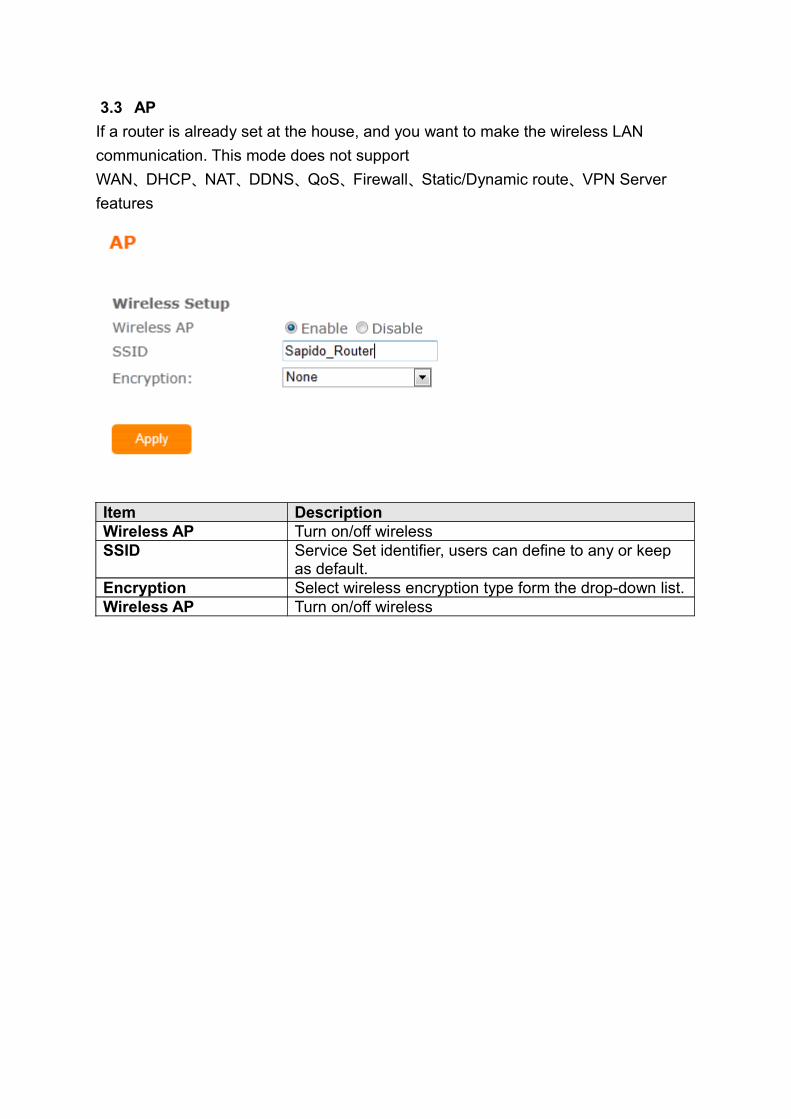
3.3 AP
If a router is already set at the house, and you want to make the wireless LAN
communication. This mode does not support
WAN、DHCP、NAT、DDNS、QoS、Firewall、Static/Dynamic route、VPN Server
features
Item DescriptionWireless AP Turn on/off wirelessSSID Service Set identifier, users can define to any or keep
as default.Encryption Select wireless encryption type form the drop-down list.Wireless AP Turn on/off wireless
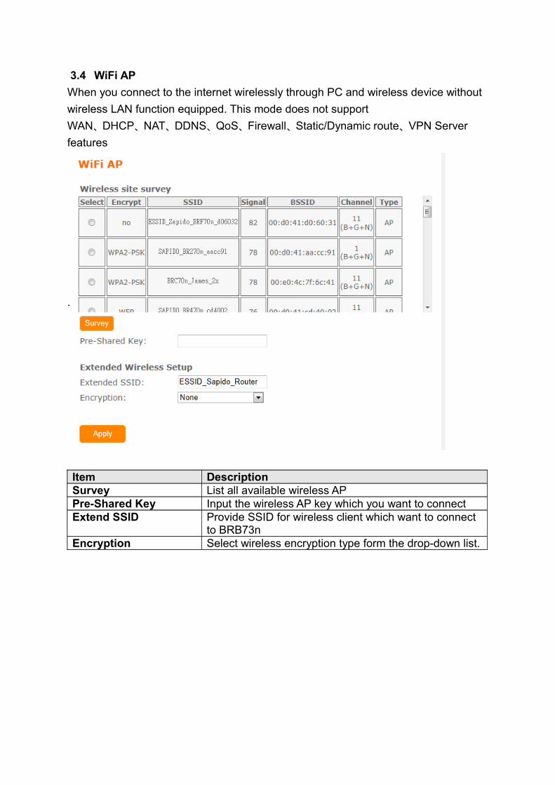
3.4 WiFi AP
When you connect to the internet wirelessly through PC and wireless device without
wireless LAN function equipped. This mode does not support
WAN、DHCP、NAT、DDNS、QoS、Firewall、Static/Dynamic route、VPN Server
features
.
Item DescriptionSurvey List all available wireless APPre-Shared Key Input the wireless AP key which you want to connectExtend SSID Provide SSID for wireless client which want to connect
to BRB73nEncryption Select wireless encryption type form the drop-down list.
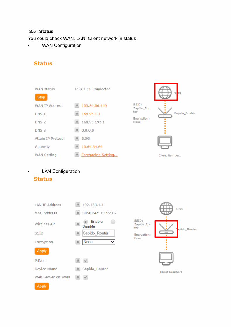
3.5 Status
You could check WAN, LAN, Client network in status
• WAN Configuration
• LAN Configuration
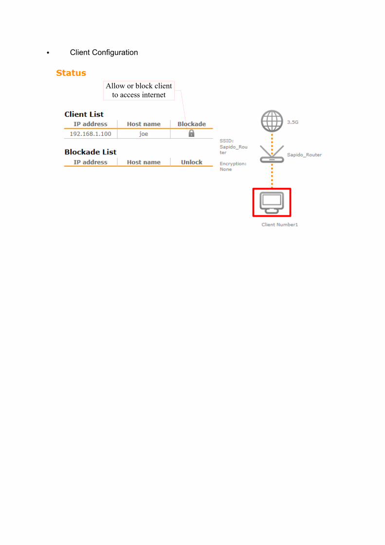
• Client Configuration
Allow or block client to access internet
3.6 Parental Control
Parental Control provide URL Filtering and MAC Filter Schedule for setup
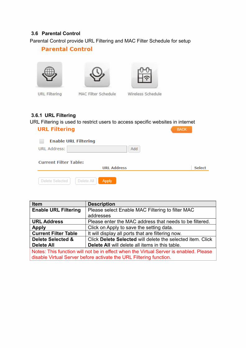
3.6.1 URL FilteringURL Filtering is used to restrict users to access specific websites in internet
Item DescriptionEnable URL Filtering Please select Enable MAC Filtering to filter MAC
addressesURL Address Please enter the MAC address that needs to be filtered.Apply Click on Apply to save the setting data. Current Filter Table It will display all ports that are filtering now.Delete Selected & Delete All
Click Delete Selected will delete the selected item. Click Delete All will delete all items in this table.
Notes: This function will not be in effect when the Virtual Server is enabled. Please disable Virtual Server before activate the URL Filtering function.
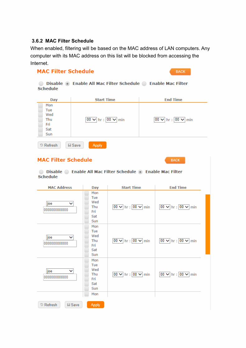
3.6.2 MAC Filter Schedule
When enabled, filtering will be based on the MAC address of LAN computers. Any
computer with its MAC address on this list will be blocked from accessing the
Internet.
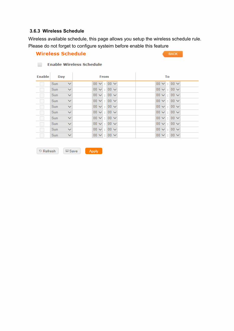
3.6.3 Wireless Schedule
Wireless available schedule, this page allows you setup the wireless schedule rule.
Please do not forget to configure systeim before enable this feature
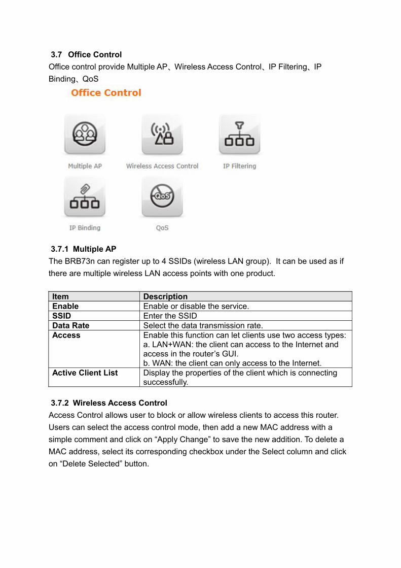
3.7 Office Control
Office control provide Multiple AP、Wireless Access Control、IP Filtering、IP
Binding、QoS
3.7.1 Multiple AP
The BRB73n can register up to 4 SSIDs (wireless LAN group). It can be used as if
there are multiple wireless LAN access points with one product.
Item DescriptionEnable Enable or disable the service.SSID Enter the SSIDData Rate Select the data transmission rate.Access Enable this function can let clients use two access types:
a. LAN+WAN: the client can access to the Internet and access in the router’s GUI. b. WAN: the client can only access to the Internet.
Active Client List Display the properties of the client which is connecting successfully.
3.7.2 Wireless Access Control
Access Control allows user to block or allow wireless clients to access this router.
Users can select the access control mode, then add a new MAC address with a
simple comment and click on “Apply Change” to save the new addition. To delete a
MAC address, select its corresponding checkbox under the Select column and click
on “Delete Selected” button.
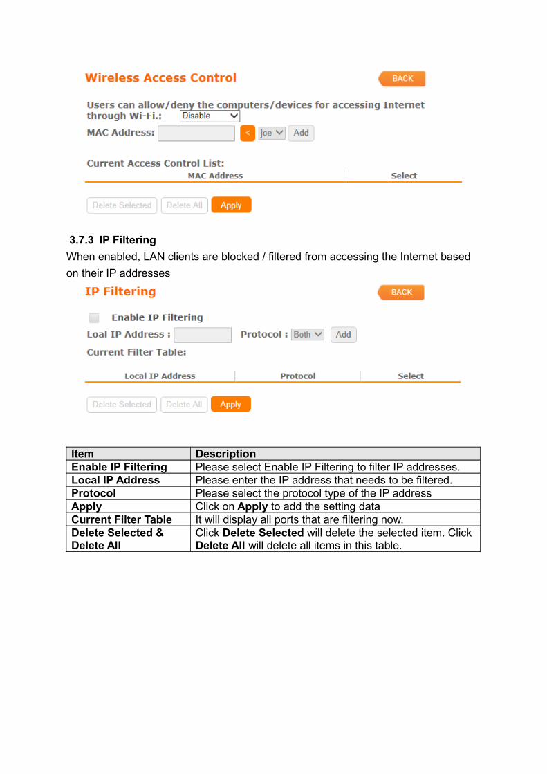
3.7.3 IP Filtering
When enabled, LAN clients are blocked / filtered from accessing the Internet based
on their IP addresses
Item DescriptionEnable IP Filtering Please select Enable IP Filtering to filter IP addresses.Local IP Address Please enter the IP address that needs to be filtered.Protocol Please select the protocol type of the IP addressApply Click on Apply to add the setting dataCurrent Filter Table It will display all ports that are filtering now.Delete Selected & Delete All
Click Delete Selected will delete the selected item. Click Delete All will delete all items in this table.
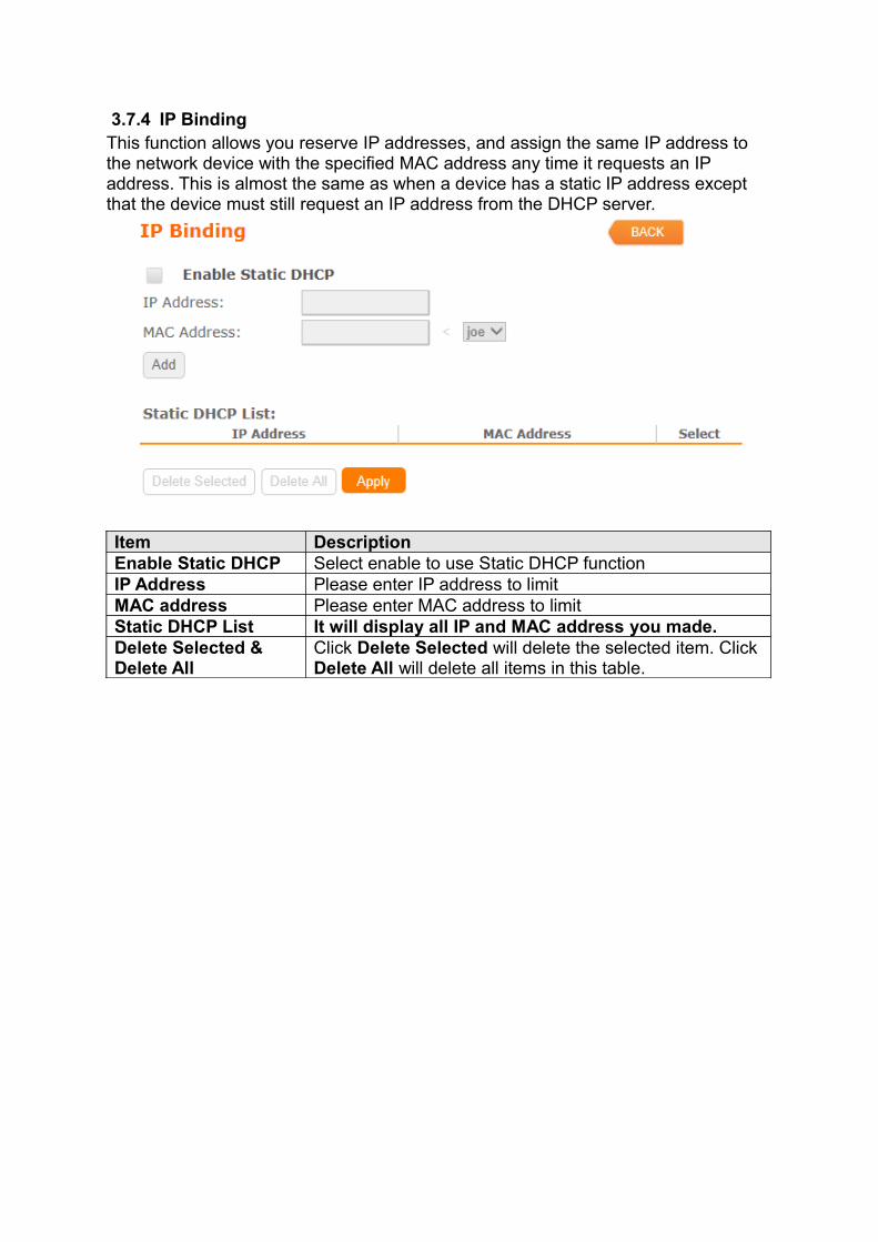
3.7.4 IP BindingThis function allows you reserve IP addresses, and assign the same IP address to the network device with the specified MAC address any time it requests an IP address. This is almost the same as when a device has a static IP address except that the device must still request an IP address from the DHCP server.
Item DescriptionEnable Static DHCP Select enable to use Static DHCP functionIP Address Please enter IP address to limitMAC address Please enter MAC address to limitStatic DHCP List It will display all IP and MAC address you made.Delete Selected & Delete All
Click Delete Selected will delete the selected item. Click Delete All will delete all items in this table.
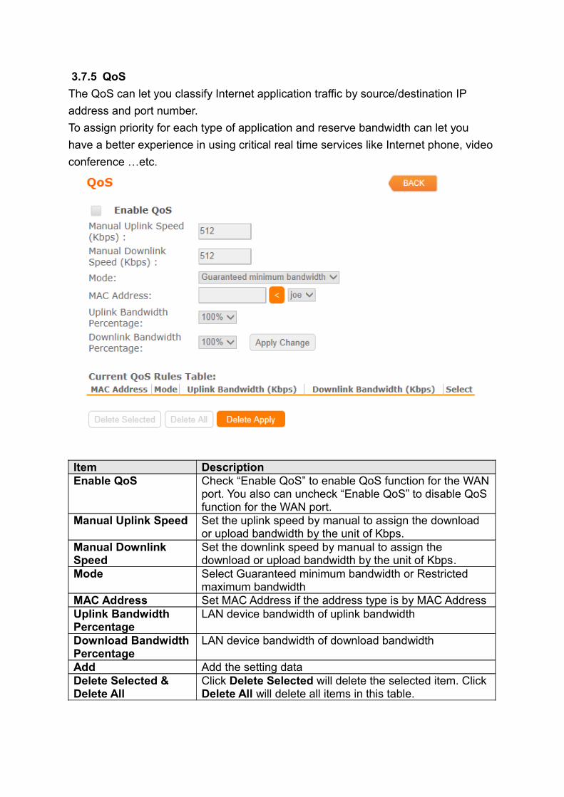
3.7.5 QoS
The QoS can let you classify Internet application traffic by source/destination IP
address and port number.
To assign priority for each type of application and reserve bandwidth can let you
have a better experience in using critical real time services like Internet phone, video
conference …etc.
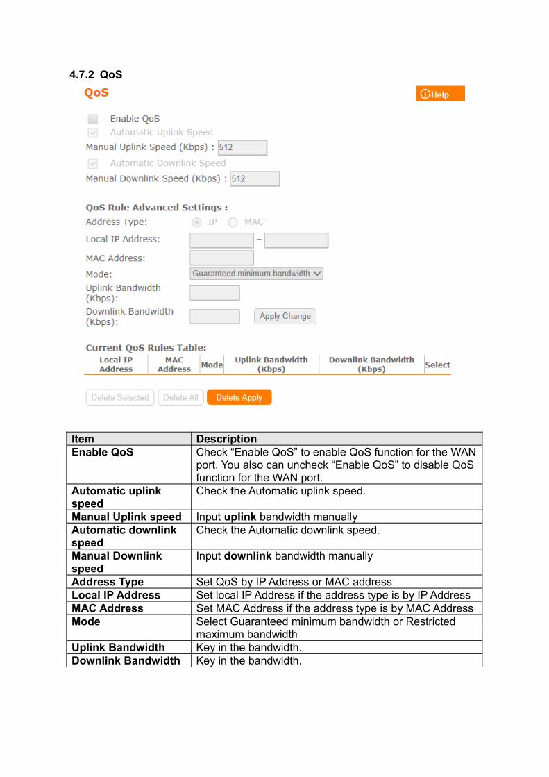
Item DescriptionEnable QoS Check “Enable QoS” to enable QoS function for the WAN
port. You also can uncheck “Enable QoS” to disable QoS function for the WAN port.
Manual Uplink Speed Set the uplink speed by manual to assign the download or upload bandwidth by the unit of Kbps.
Manual Downlink Speed
Set the downlink speed by manual to assign the download or upload bandwidth by the unit of Kbps.
Mode Select Guaranteed minimum bandwidth or Restricted maximum bandwidth
MAC Address Set MAC Address if the address type is by MAC AddressUplink Bandwidth Percentage
LAN device bandwidth of uplink bandwidth
Download Bandwidth Percentage
LAN device bandwidth of download bandwidth
Add Add the setting dataDelete Selected & Delete All
Click Delete Selected will delete the selected item. Click Delete All will delete all items in this table.
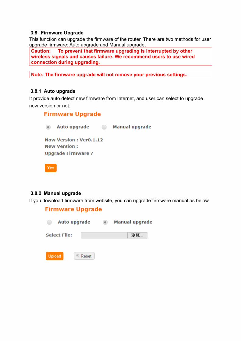
3.8 Firmware UpgradeThis function can upgrade the firmware of the router. There are two methods for user upgrade firmware: Auto upgrade and Manual upgrade.Caution: To prevent that firmware upgrading is interrupted by other wireless signals and causes failure. We recommend users to use wired connection during upgrading.
Note: The firmware upgrade will not remove your previous settings.
3.8.1 Auto upgrade
It provide auto detect new firmware from Internet, and user can select to upgrade
new version or not.
3.8.2 Manual upgrade
If you download firmware from website, you can upgrade firmware manual as below.
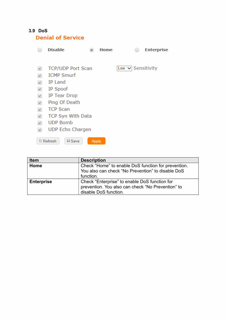
3.9 DoS
Item DescriptionHome Check “Home” to enable DoS function for prevention.
You also can check “No Prevention” to disable DoS function.
Enterprise Check “Enterprise” to enable DoS function for prevention. You also can check “No Prevention” to disable DoS function.
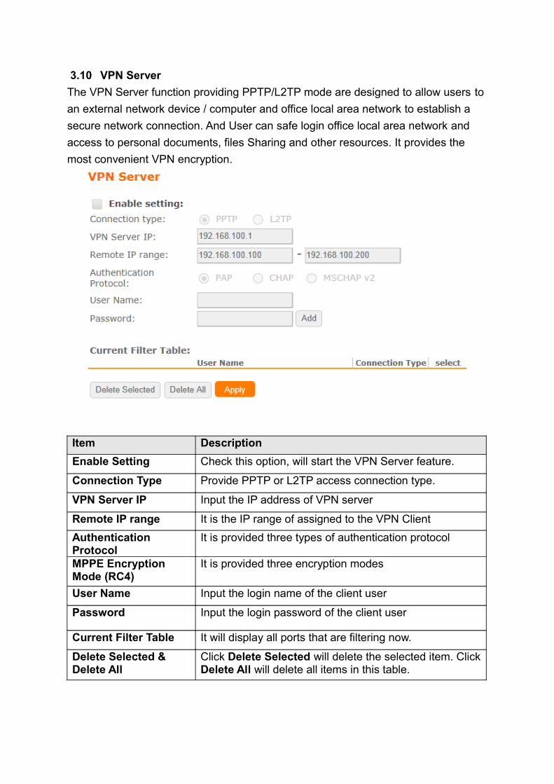
3.10 VPN Server
The VPN Server function providing PPTP/L2TP mode are designed to allow users to
an external network device / computer and office local area network to establish a
secure network connection. And User can safe login office local area network and
access to personal documents, files Sharing and other resources. It provides the
most convenient VPN encryption.
Item Description
Enable Setting Check this option, will start the VPN Server feature.
Connection Type Provide PPTP or L2TP access connection type.
VPN Server IP Input the IP address of VPN server
Remote IP range It is the IP range of assigned to the VPN Client
Authentication Protocol
It is provided three types of authentication protocol
MPPE Encryption Mode (RC4)
It is provided three encryption modes
User Name Input the login name of the client user
Password Input the login password of the client user
Current Filter Table It will display all ports that are filtering now.
Delete Selected & Delete All
Click Delete Selected will delete the selected item. Click Delete All will delete all items in this table.
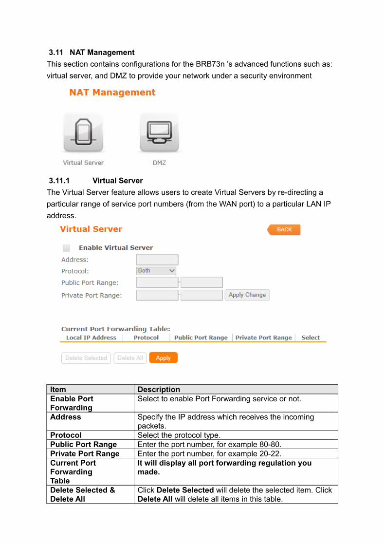
3.11 NAT Management
This section contains configurations for the BRB73n ’s advanced functions such as:
virtual server, and DMZ to provide your network under a security environment
3.11.1 Virtual Server
The Virtual Server feature allows users to create Virtual Servers by re-directing a
particular range of service port numbers (from the WAN port) to a particular LAN IP
address.
Item DescriptionEnable Port Forwarding
Select to enable Port Forwarding service or not.
Address Specify the IP address which receives the incoming packets.
Protocol Select the protocol type.Public Port Range Enter the port number, for example 80-80.Private Port Range Enter the port number, for example 20-22.Current Port Forwarding Table
It will display all port forwarding regulation you made.
Delete Selected & Delete All
Click Delete Selected will delete the selected item. Click Delete All will delete all items in this table.
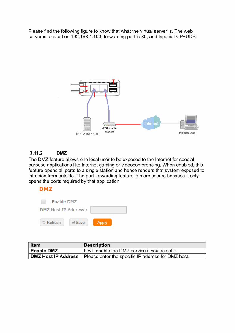
Please find the following figure to know that what the virtual server is. The web server is located on 192.168.1.100, forwarding port is 80, and type is TCP+UDP.
3.11.2 DMZThe DMZ feature allows one local user to be exposed to the Internet for special-purpose applications like Internet gaming or videoconferencing. When enabled, this feature opens all ports to a single station and hence renders that system exposed to intrusion from outside. The port forwarding feature is more secure because it only opens the ports required by that application.
Item DescriptionEnable DMZ It will enable the DMZ service if you select it.DMZ Host IP Address Please enter the specific IP address for DMZ host.

3.12 Send SMS
BRB73n allow user to send text message by 3.5G network
Item DescriptionPhone Number Phone number which user want to send text message to.
3.13 Factory Default
You could reset the current configuration to factory default.
3.14 Reboot
This function is used to reboot
3.15 Logout
This page is used to logout
4 Advance Setup
4.1 Internet Mode
4.1.1 Internet Setup
Please refer Internet Setup
4.1.2 AP(switch to AP mode )Please refer AP mode
4.1.3 WiFi AP(switch to WiFi AP mode)Please refer WiFi AP mode
4.1.4 WiFi ISP
Please refer WiFi ISP mode
4.2 IP Config
4.2.1 WAN
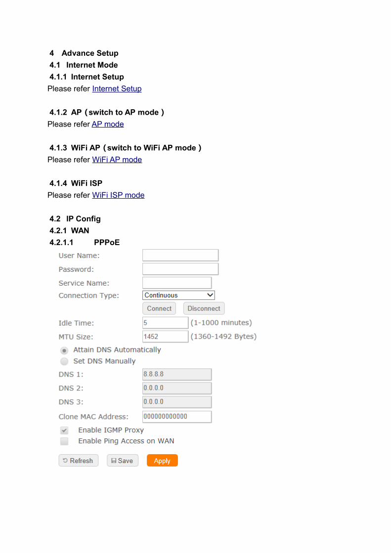
4.2.1.1 PPPoE
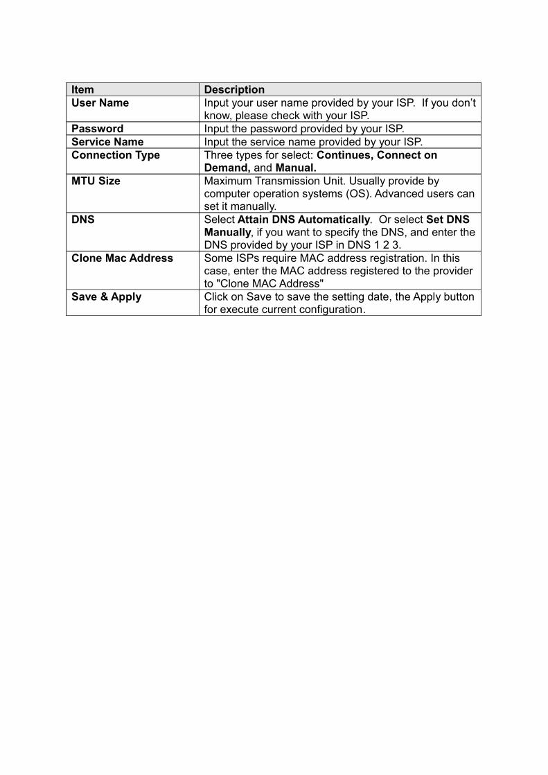
Item DescriptionUser Name Input your user name provided by your ISP. If you don’t
know, please check with your ISP. Password Input the password provided by your ISP.Service Name Input the service name provided by your ISP.Connection Type Three types for select: Continues, Connect on
Demand, and Manual.MTU Size Maximum Transmission Unit. Usually provide by
computer operation systems (OS). Advanced users can set it manually.
DNS Select Attain DNS Automatically. Or select Set DNS Manually, if you want to specify the DNS, and enter the DNS provided by your ISP in DNS 1 2 3.
Clone Mac Address Some ISPs require MAC address registration. In this case, enter the MAC address registered to the provider to "Clone MAC Address"
Save & Apply Click on Save to save the setting date, the Apply button for execute current configuration.
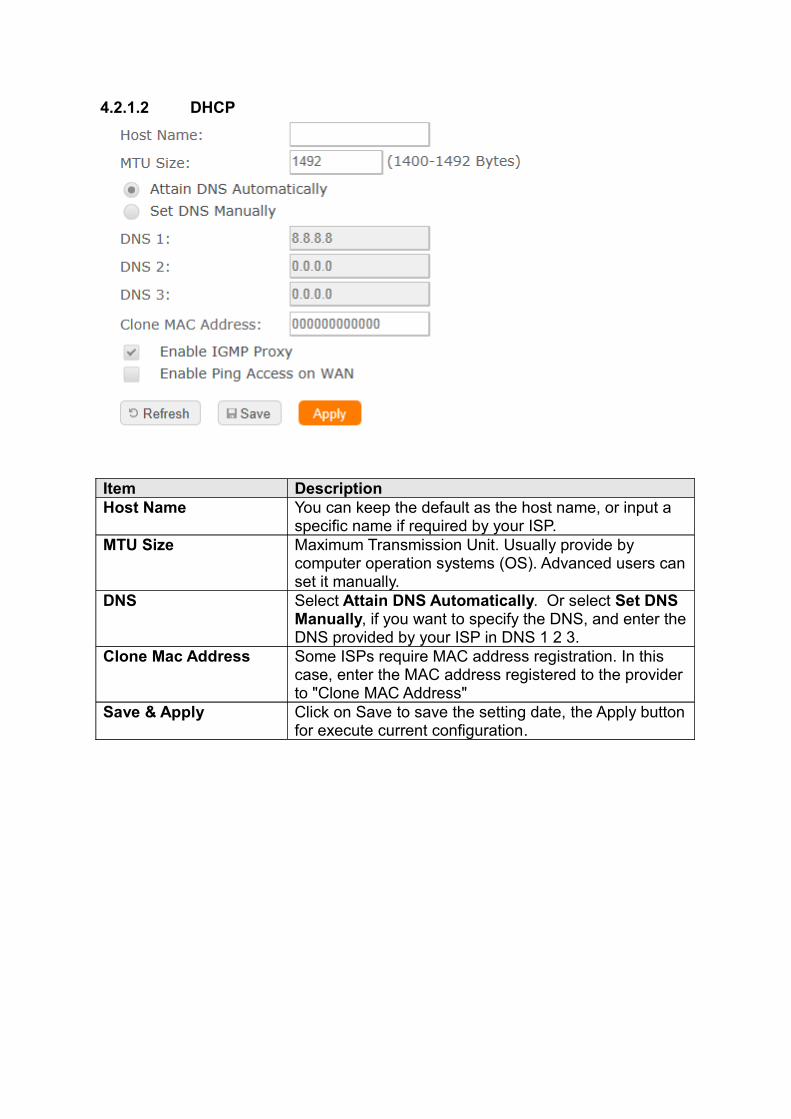
4.2.1.2 DHCP
Item DescriptionHost Name You can keep the default as the host name, or input a
specific name if required by your ISP. MTU Size Maximum Transmission Unit. Usually provide by
computer operation systems (OS). Advanced users can set it manually.
DNS Select Attain DNS Automatically. Or select Set DNS Manually, if you want to specify the DNS, and enter the DNS provided by your ISP in DNS 1 2 3.
Clone Mac Address Some ISPs require MAC address registration. In this case, enter the MAC address registered to the provider to "Clone MAC Address"
Save & Apply Click on Save to save the setting date, the Apply button for execute current configuration.
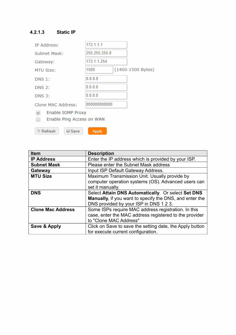
4.2.1.3 Static IP
Item DescriptionIP Address Enter the IP address which is provided by your ISP. Subnet Mask Please enter the Subnet Mask addressGateway Input ISP Default Gateway Address.MTU Size Maximum Transmission Unit. Usually provide by
computer operation systems (OS). Advanced users can set it manually.
DNS Select Attain DNS Automatically. Or select Set DNS Manually, if you want to specify the DNS, and enter the DNS provided by your ISP in DNS 1 2 3.
Clone Mac Address Some ISPs require MAC address registration. In this case, enter the MAC address registered to the provider to "Clone MAC Address"
Save & Apply Click on Save to save the setting date, the Apply button for execute current configuration.
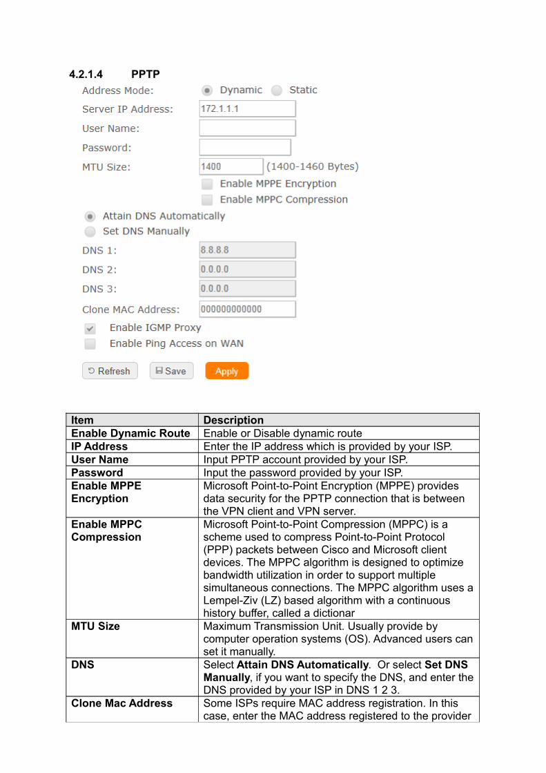
4.2.1.4 PPTP
Item DescriptionEnable Dynamic Route Enable or Disable dynamic routeIP Address Enter the IP address which is provided by your ISP. User Name Input PPTP account provided by your ISP. Password Input the password provided by your ISP.Enable MPPE Encryption
Microsoft Point-to-Point Encryption (MPPE) provides data security for the PPTP connection that is between the VPN client and VPN server.
Enable MPPC Compression
Microsoft Point-to-Point Compression (MPPC) is a scheme used to compress Point-to-Point Protocol (PPP) packets between Cisco and Microsoft client devices. The MPPC algorithm is designed to optimize bandwidth utilization in order to support multiple simultaneous connections. The MPPC algorithm uses a Lempel-Ziv (LZ) based algorithm with a continuous history buffer, called a dictionar
MTU Size Maximum Transmission Unit. Usually provide by computer operation systems (OS). Advanced users can set it manually.
DNS Select Attain DNS Automatically. Or select Set DNS Manually, if you want to specify the DNS, and enter the DNS provided by your ISP in DNS 1 2 3.
Clone Mac Address Some ISPs require MAC address registration. In this case, enter the MAC address registered to the provider
to "Clone MAC Address"Save & Apply Click on Save to save the setting date, the Apply button
for execute current configuration.
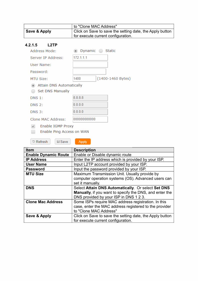
4.2.1.5 L2TP
Item DescriptionEnable Dynamic Route Enable or Disable dynamic routeIP Address Enter the IP address which is provided by your ISP. User Name Input L2TP account provided by your ISP. Password Input the password provided by your ISP.MTU Size Maximum Transmission Unit. Usually provide by
computer operation systems (OS). Advanced users can set it manually.
DNS Select Attain DNS Automatically. Or select Set DNS Manually, if you want to specify the DNS, and enter the DNS provided by your ISP in DNS 1 2 3.
Clone Mac Address Some ISPs require MAC address registration. In this case, enter the MAC address registered to the provider to "Clone MAC Address"
Save & Apply Click on Save to save the setting date, the Apply button for execute current configuration.
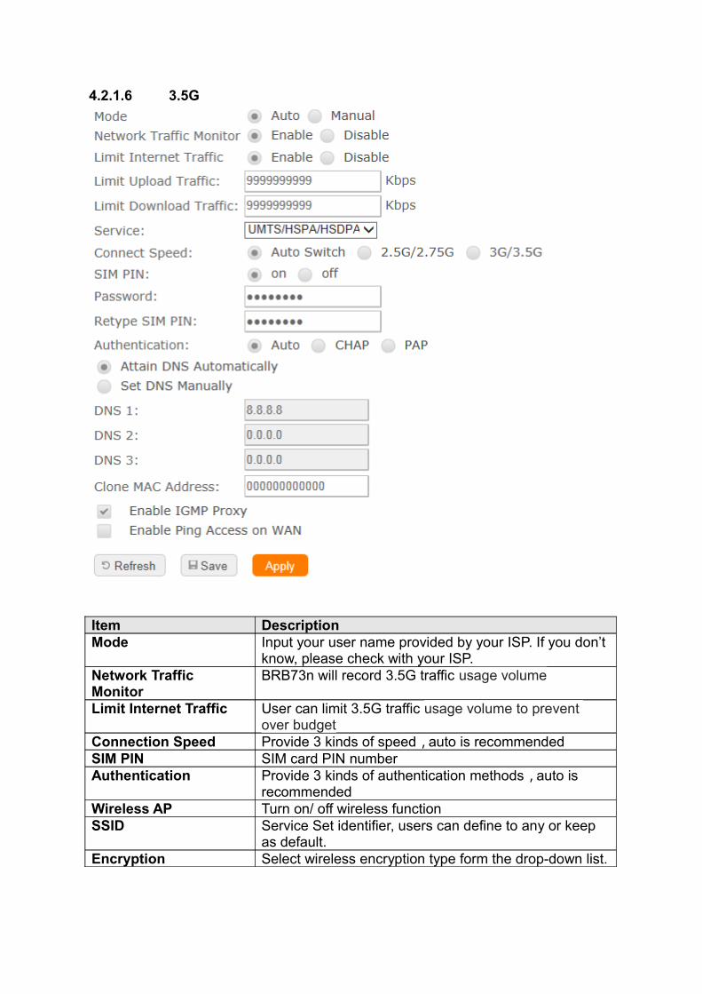
4.2.1.6 3.5G
Item DescriptionMode Input your user name provided by your ISP. If you don’t
know, please check with your ISP. Network Traffic Monitor
BRB73n will record 3.5G traffic usage volume
Limit Internet Traffic User can limit 3.5G traffic usage volume to prevent over budget
Connection Speed Provide 3 kinds of speed,auto is recommendedSIM PIN SIM card PIN numberAuthentication Provide 3 kinds of authentication methods,auto is
recommendedWireless AP Turn on/ off wireless functionSSID Service Set identifier, users can define to any or keep
as default.Encryption Select wireless encryption type form the drop-down list.
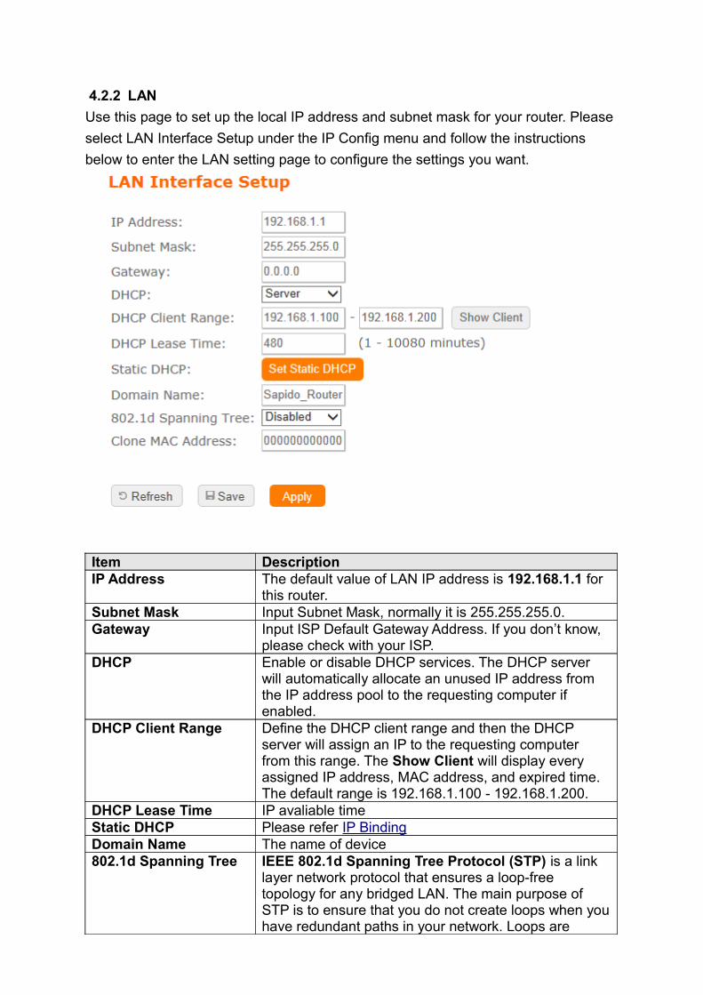
4.2.2 LAN
Use this page to set up the local IP address and subnet mask for your router. Please
select LAN Interface Setup under the IP Config menu and follow the instructions
below to enter the LAN setting page to configure the settings you want.
Item DescriptionIP Address The default value of LAN IP address is 192.168.1.1 for
this router.Subnet Mask Input Subnet Mask, normally it is 255.255.255.0.Gateway Input ISP Default Gateway Address. If you don’t know,
please check with your ISP.DHCP Enable or disable DHCP services. The DHCP server
will automatically allocate an unused IP address from the IP address pool to the requesting computer if enabled.
DHCP Client Range Define the DHCP client range and then the DHCP server will assign an IP to the requesting computer from this range. The Show Client will display every assigned IP address, MAC address, and expired time. The default range is 192.168.1.100 - 192.168.1.200.
DHCP Lease Time IP avaliable timeStatic DHCP Please refer IP BindingDomain Name The name of device802.1d Spanning Tree IEEE 802.1d Spanning Tree Protocol (STP) is a link
layer network protocol that ensures a loop-free topology for any bridged LAN. The main purpose of STP is to ensure that you do not create loops when you have redundant paths in your network. Loops are
deadly to a network.Clone MAC Address Copy the MAC address from the device you had
registered to your ISP if your ISP asks for the specific MAC Address.
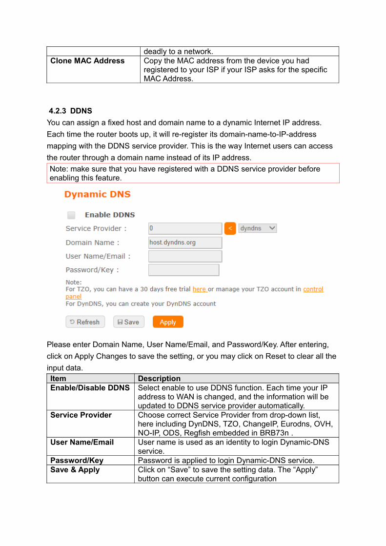
4.2.3 DDNS
You can assign a fixed host and domain name to a dynamic Internet IP address.
Each time the router boots up, it will re-register its domain-name-to-IP-address
mapping with the DDNS service provider. This is the way Internet users can access
the router through a domain name instead of its IP address.
Note: make sure that you have registered with a DDNS service provider before enabling this feature.
Please enter Domain Name, User Name/Email, and Password/Key. After entering,
click on Apply Changes to save the setting, or you may click on Reset to clear all the
input data. Item DescriptionEnable/Disable DDNS Select enable to use DDNS function. Each time your IP
address to WAN is changed, and the information will be updated to DDNS service provider automatically.
Service Provider Choose correct Service Provider from drop-down list, here including DynDNS, TZO, ChangeIP, Eurodns, OVH, NO-IP, ODS, Regfish embedded in BRB73n .
User Name/Email User name is used as an identity to login Dynamic-DNS service.
Password/Key Password is applied to login Dynamic-DNS service.Save & Apply Click on “Save” to save the setting data. The “Apply”
button can execute current configuration
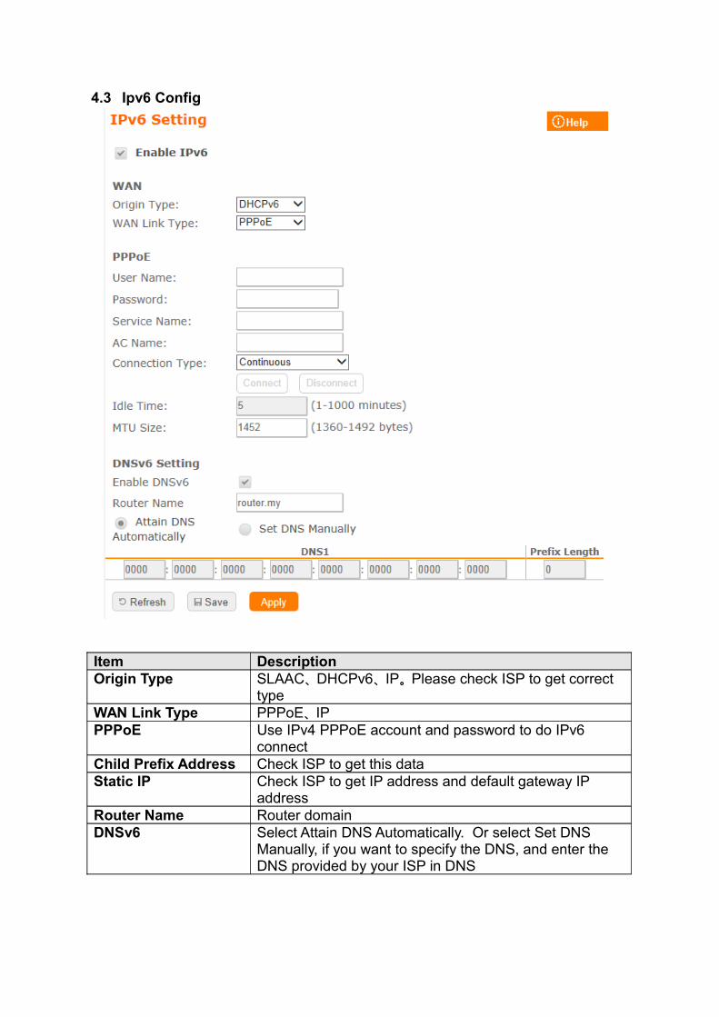
4.3 Ipv6 Config
Item DescriptionOrigin Type SLAAC、DHCPv6、IP。Please check ISP to get correct
typeWAN Link Type PPPoE、IPPPPoE Use IPv4 PPPoE account and password to do IPv6
connectChild Prefix Address Check ISP to get this dataStatic IP Check ISP to get IP address and default gateway IP
addressRouter Name Router domainDNSv6 Select Attain DNS Automatically. Or select Set DNS
Manually, if you want to specify the DNS, and enter the DNS provided by your ISP in DNS
4.4 Wireless
4.4.1 Wireless Basic Settings
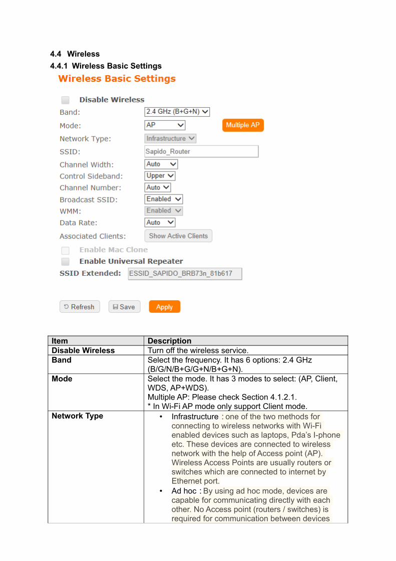
Item DescriptionDisable Wireless Turn off the wireless service.Band Select the frequency. It has 6 options: 2.4 GHz
(B/G/N/B+G/G+N/B+G+N).Mode Select the mode. It has 3 modes to select: (AP, Client,
WDS, AP+WDS).Multiple AP: Please check Section 4.1.2.1.* In Wi-Fi AP mode only support Client mode.
Network Type • Infrastructure:one of the two methods for connecting to wireless networks with Wi-Fi enabled devices such as laptops, Pda’s I-phone etc. These devices are connected to wireless network with the help of Access point (AP). Wireless Access Points are usually routers or switches which are connected to internet by Ethernet port.
• Ad hoc:By using ad hoc mode, devices are capable for communicating directly with each other. No Access point (routers / switches) is required for communication between devices
and all devices in the range connect in peer to peer communication mode.
SSID Service Set identifier, users can define to any or keep as default.
Channel Width Please select the channel width, it has 3 options: 20MHz / 40MHz / Auto
Control Sideband Enable this function will control your router use lower or upper channel.
Channel Number Please select the channel; it has Auto, 1, 2~11 or 13 options.
Broadband SSID User may choose to enable Broadcast SSID or not.WMM Enable / Disable Wi-Fi MultimediaData Rate Please select the data transmission rate.Associate Clients Check the AP connectors and the Wireless connecting
status.Enable MAC Clone (Single Ethernet Client)
Clone the MAC address for ISP to identify.
Enable Universal Repeater Mode (Acting as AP and Client simultaneously)
Allow to equip with the wireless way conjunction upper level, provide the bottom layer user link in wireless and wired way in the meantime. (The IP that bottom layer obtains is from upper level.) Please also check Section 4.1.2.2
SSID of Extended Interface
While linking the upper level device in wireless way, you can set SSID to give the bottom layer user search.
Multiple AP BRB73n can register up to 4 SSIDs (wireless LAN group). It can be used as if there are multiple wireless LAN access points with one product. Each SSID could be set with different data rate, WMM and access type
Save & Apply Click on “Save” to save the setting data. The “Apply” button can execute current configuration
4.4.2 Advanced Settings
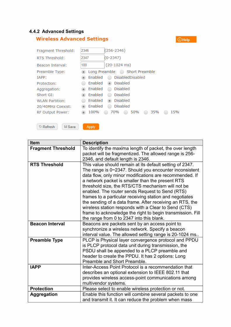
Item DescriptionFragment Threshold To identify the maxima length of packet, the over length
packet will be fragmentized. The allowed range is 256-2346, and default length is 2346.
RTS Threshold This value should remain at its default setting of 2347. The range is 0~2347. Should you encounter inconsistent data flow, only minor modifications are recommended. If a network packet is smaller than the present RTS threshold size, the RTS/CTS mechanism will not be enabled. The router sends Request to Send (RTS) frames to a particular receiving station and negotiates the sending of a data frame. After receiving an RTS, the wireless station responds with a Clear to Send (CTS) frame to acknowledge the right to begin transmission. Fill the range from 0 to 2347 into this blank.
Beacon Interval Beacons are packets sent by an access point to synchronize a wireless network. Specify a beacon interval value. The allowed setting range is 20-1024 ms..
Preamble Type PLCP is Physical layer convergence protocol and PPDU is PLCP protocol data unit during transmission, the PSDU shall be appended to a PLCP preamble and header to create the PPDU. It has 2 options: Long Preamble and Short Preamble.
IAPP Inter-Access Point Protocol is a recommendation that describes an optional extension to IEEE 802.11 that provides wireless access-point communications among multivendor systems.
Protection Please select to enable wireless protection or not.Aggregation Enable this function will combine several packets to one
and transmit it. It can reduce the problem when mass
packets are transmitting.Short GI Users can get better wireless transmission efficiency
when they enable this function.WLAN Partition Shut down the communication between the
connected wireless LAN devices.If you set up as "Enabled", devices connected with the router, such as a printer, will not be able to use. Default Setting: "Disabled"
20/40MHz Coexist Configure 20/40MHz coexisting scheme.If you set up as "Enabled", "20MHz" and "40MHz" will coexist.Normally use as "Disabled".Default Setting: "Disabled"
RF Output Power Users can adjust RF output power to get the best wireless network environment. Users can choose from 100%, 70%, 50%, 35%, and 15%.
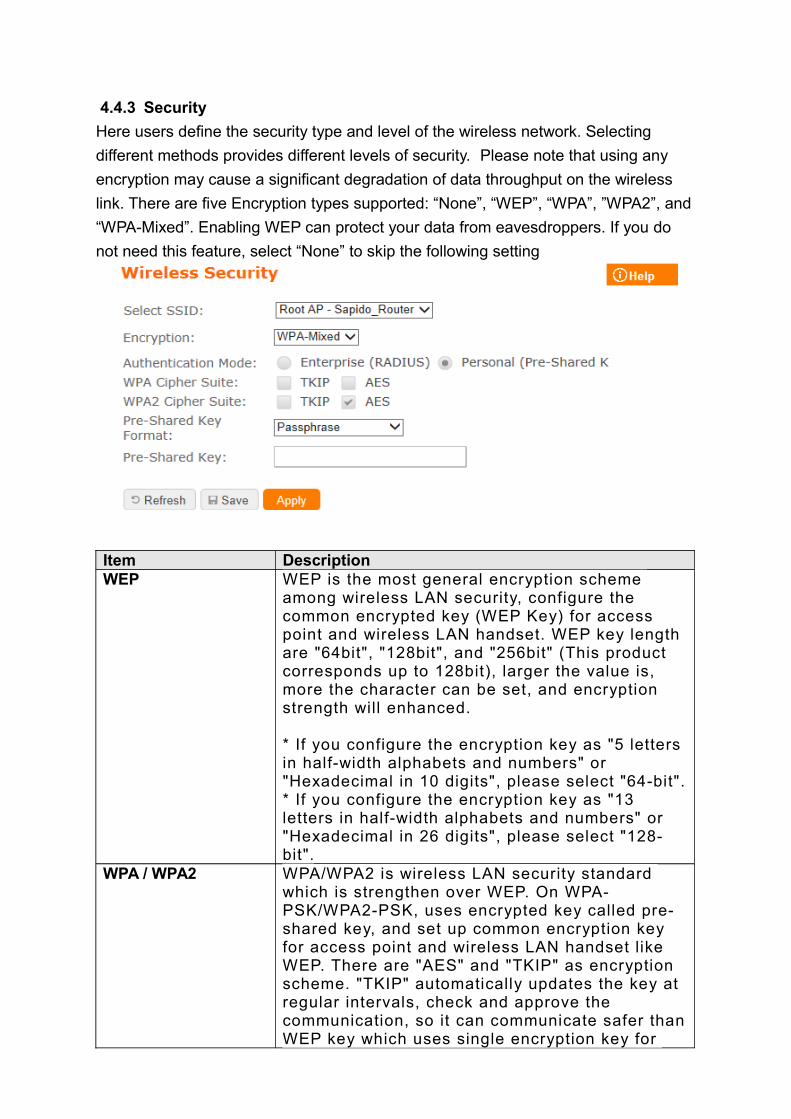
4.4.3 Security
Here users define the security type and level of the wireless network. Selecting
different methods provides different levels of security. Please note that using any
encryption may cause a significant degradation of data throughput on the wireless
link. There are five Encryption types supported: “None”, “WEP”, “WPA”, ”WPA2”, and
“WPA-Mixed”. Enabling WEP can protect your data from eavesdroppers. If you do
not need this feature, select “None” to skip the following setting
Item DescriptionWEP WEP is the most general encryption scheme
among wireless LAN security, configure the common encrypted key (WEP Key) for access point and wireless LAN handset. WEP key length are "64bit", "128bit", and "256bit" (This product corresponds up to 128bit), larger the value is, more the character can be set, and encryption strength will enhanced.
* If you configure the encryption key as "5 letters in half-width alphabets and numbers" or "Hexadecimal in 10 digits", please select "64-bit".* If you configure the encryption key as "13 letters in half-width alphabets and numbers" or "Hexadecimal in 26 digits", please select "128-bit".
WPA / WPA2 WPA/WPA2 is wireless LAN security standard which is strengthen over WEP. On WPA-PSK/WPA2-PSK, uses encrypted key called pre-shared key, and set up common encryption key for access point and wireless LAN handset like WEP. There are "AES" and "TKIP" as encryption scheme. "TKIP" automatically updates the key at regular intervals, check and approve the communication, so it can communicate safer than WEP key which uses single encryption key for
long time. "AES" is harder to decode comparing to "TKIP", so it can say tougher encryption scheme than "TKIP"
WPA-Mixed Support WPA and WPA2 at the same time802.1x AuthenticationRadius
For radius server authentication
Personal (Pre-Shared Key)
* If you configure Pre-Shared Key as "Hexadecimal in 64 digits", please select "Hex (64 characters) ".* If you configure encryption key in "8 to 63 letters in half-width alphabets and numbers", please select "Passphrase
4.4.4 Access Control
Please refer Wireless Access Control
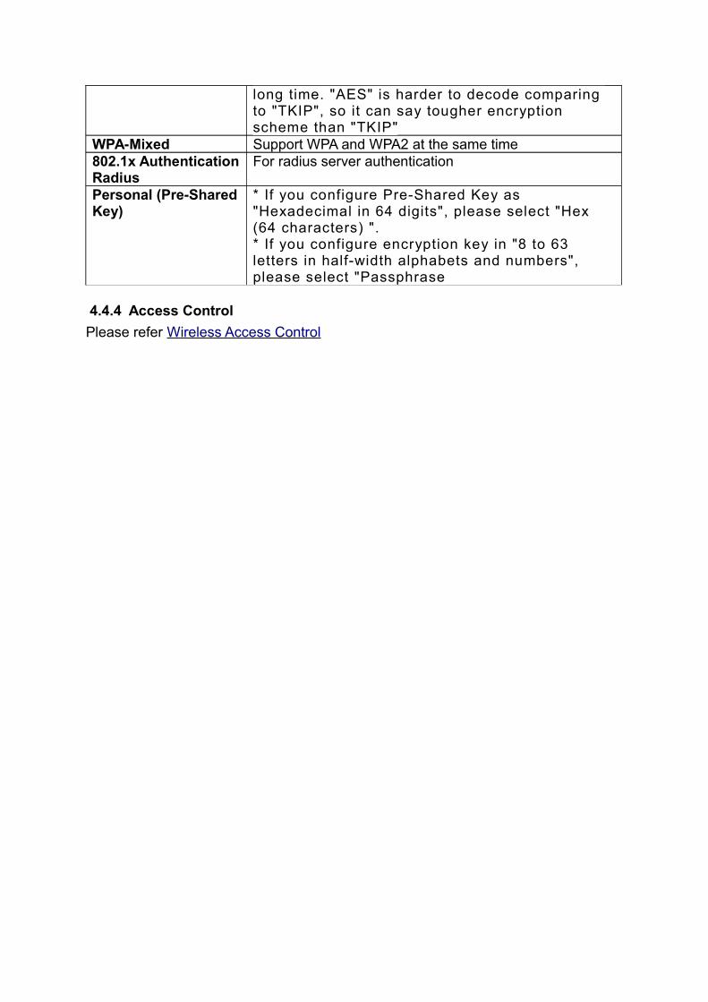
4.4.5 WPSThis page allows user to change the setting for WPS (Wi-Fi Protected Setup). Using this feature could let your wireless client atomically synchronize it’s setting and connect to the Access Point in a minute without any hassle. SAPIDO BRB73n could support both Self-PIN or PBC modes, or use the WPS button (at real panel) to easy enable the WPS function. PIN model, in which a PIN has to be taken either from a sticker label or from the web interface of the WPS device. This PIN will then be entered in the AP or client WPS device to connect. PBC model, in which the user simply has to push a button, either an actual or a virtual one, on both WPS devices to connect.
BRB73n WPS only support no encryption and WPA2
Please follow instructions below to enable the WPS function. • Setup Wireless LAN with WPS PIN :
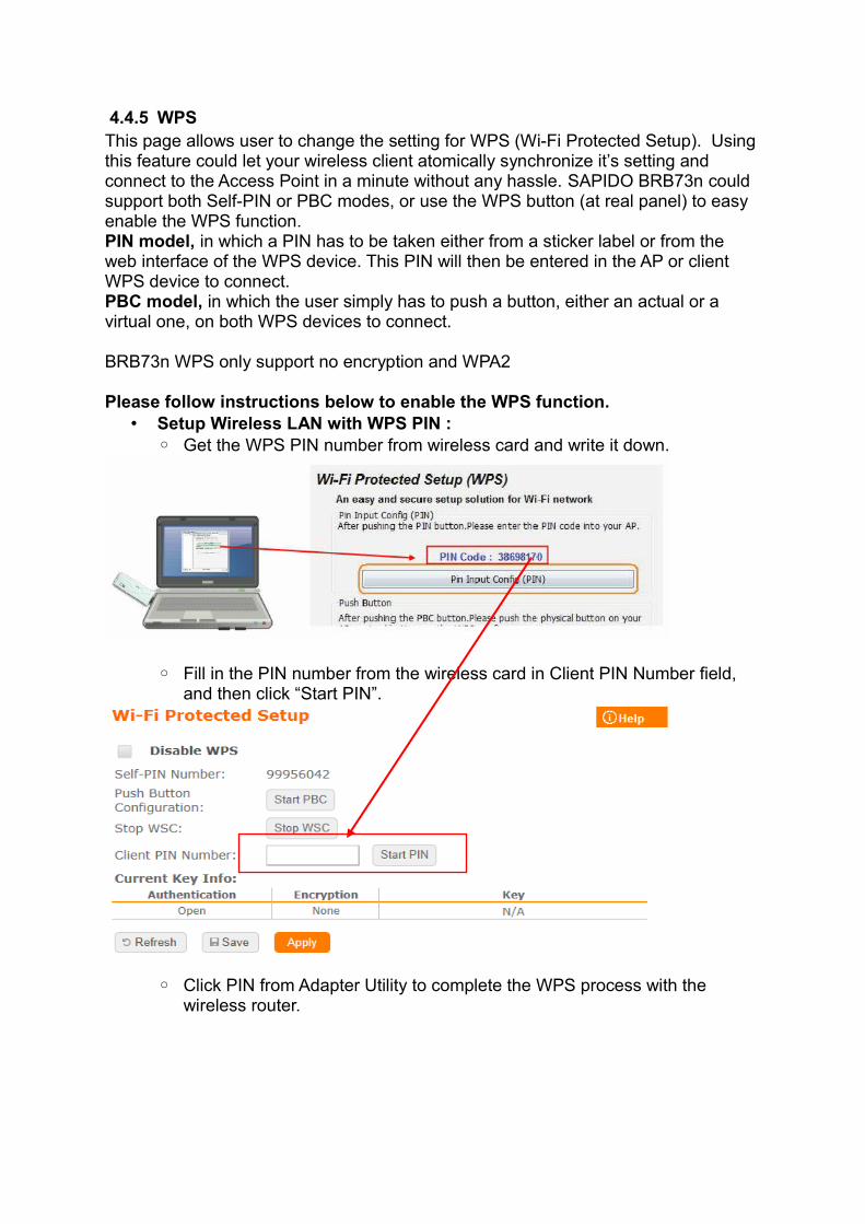
◦ Get the WPS PIN number from wireless card and write it down.
◦ Fill in the PIN number from the wireless card in Client PIN Number field, and then click “Start PIN”.
◦ Click PIN from Adapter Utility to complete the WPS process with the wireless router.
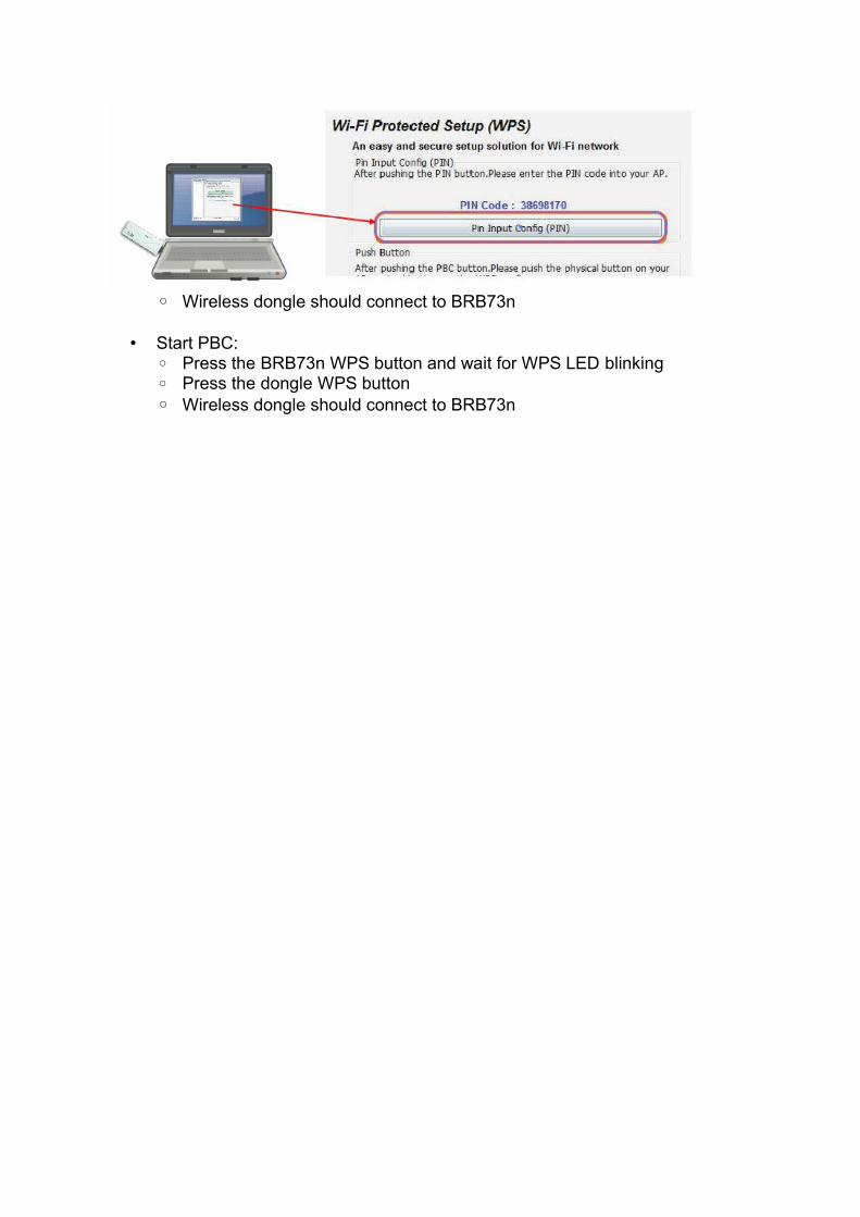
◦ Wireless dongle should connect to BRB73n
• Start PBC:◦ Press the BRB73n WPS button and wait for WPS LED blinking◦ Press the dongle WPS button◦ Wireless dongle should connect to BRB73n
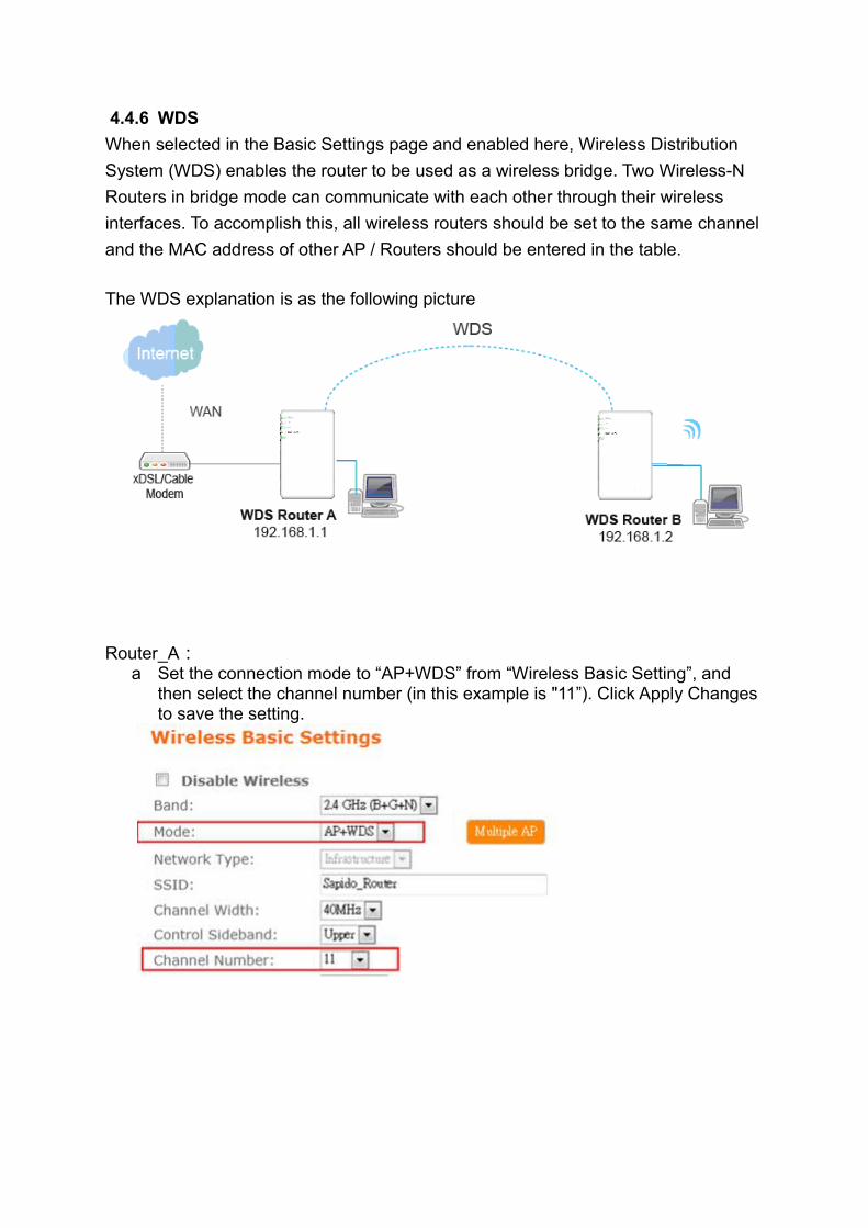
4.4.6 WDS
When selected in the Basic Settings page and enabled here, Wireless Distribution
System (WDS) enables the router to be used as a wireless bridge. Two Wireless-N
Routers in bridge mode can communicate with each other through their wireless
interfaces. To accomplish this, all wireless routers should be set to the same channel
and the MAC address of other AP / Routers should be entered in the table.
The WDS explanation is as the following picture
Router_A:a Set the connection mode to “AP+WDS” from “Wireless Basic Setting”, and
then select the channel number (in this example is "11”). Click Apply Changes to save the setting.
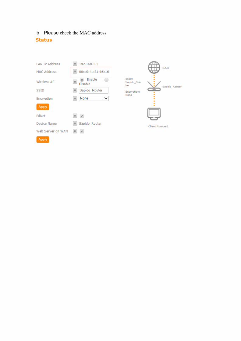
b Please check the MAC address

c Enable WDS function from the page – “WDS Setting”, and then fill in the MAC
address of Router_B. Click Apply Changes to save the setting data
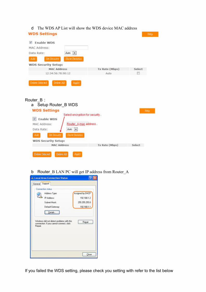
d The WDS AP List will show the WDS device MAC address
Router_B:a Setup Router_B WDS
b Router_B LAN PC will get IP address from Router_A
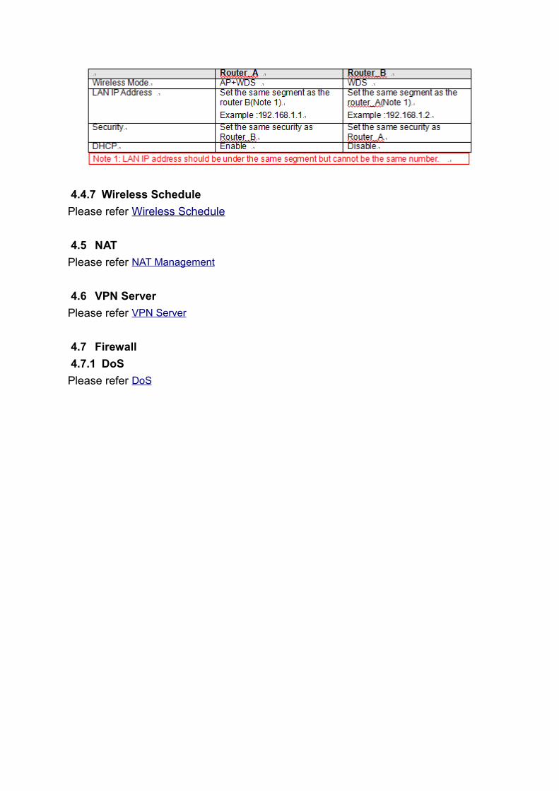
If you failed the WDS setting, please check you setting with refer to the list below
4.4.7 Wireless Schedule
Please refer Wireless Schedule
4.5 NAT
Please refer NAT Management
4.6 VPN Server
Please refer VPN Server
4.7 Firewall
4.7.1 DoS
Please refer DoS
4.7.2 QoS
Item DescriptionEnable QoS Check “Enable QoS” to enable QoS function for the WAN
port. You also can uncheck “Enable QoS” to disable QoS function for the WAN port.
Automatic uplink speed
Check the Automatic uplink speed.
Manual Uplink speed Input uplink bandwidth manuallyAutomatic downlink speed
Check the Automatic downlink speed.
Manual Downlink speed
Input downlink bandwidth manually
Address Type Set QoS by IP Address or MAC addressLocal IP Address Set local IP Address if the address type is by IP AddressMAC Address Set MAC Address if the address type is by MAC AddressMode Select Guaranteed minimum bandwidth or Restricted
maximum bandwidthUplink Bandwidth Key in the bandwidth.Downlink Bandwidth Key in the bandwidth.
4.7.3 Port Filtering
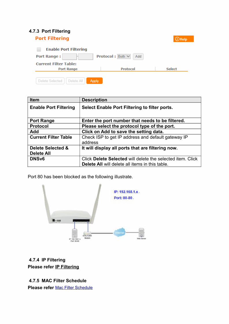
Item Description
Enable Port Filtering Select Enable Port Filtering to filter ports.
Port Range Enter the port number that needs to be filtered.Protocol Please select the protocol type of the port.Add Click on Add to save the setting data. Current Filter Table Check ISP to get IP address and default gateway IP
addressDelete Selected & Delete All
It will display all ports that are filtering now.
DNSv6 Click Delete Selected will delete the selected item. Click Delete All will delete all items in this table.
Port 80 has been blocked as the following illustrate.
4.7.4 IP Filtering
Please refer IP Filtering
4.7.5 MAC Filter Schedule
Please refer Mac Filter Schedule
4.7.6 URL Filtering
Please refer URL Filtering
4.7.7 IP Binding
Please refer IP Binding
4.7.8 VLAN
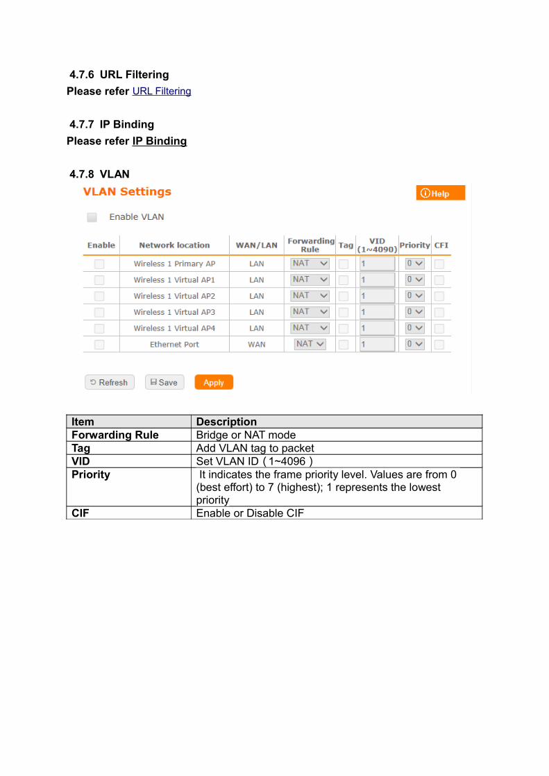
Item DescriptionForwarding Rule Bridge or NAT modeTag Add VLAN tag to packetVID Set VLAN ID(1~4096 )Priority It indicates the frame priority level. Values are from 0
(best effort) to 7 (highest); 1 represents the lowest priority
CIF Enable or Disable CIF
4.8 System Management
This section including Wake on LAN, Change Username/Password, Upgrade
Firmware, Profiles Save, Remote Management, Time Zone, UPnP, Route Setup,
VPN Passthrough, and Wan Type Auto Detection. It is easy and helpful for users
making more detailed settings
.
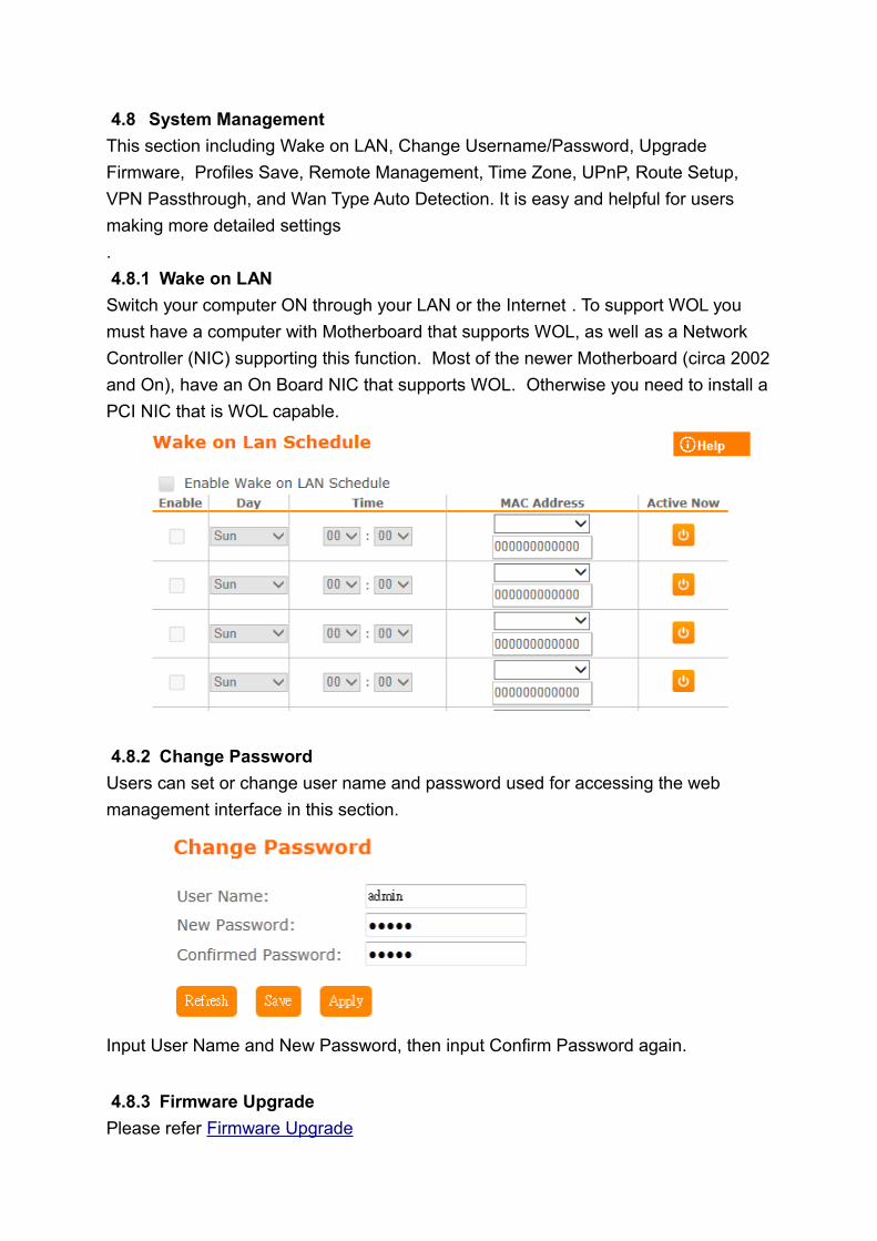
4.8.1 Wake on LAN
Switch your computer ON through your LAN or the Internet . To support WOL you
must have a computer with Motherboard that supports WOL, as well as a Network
Controller (NIC) supporting this function. Most of the newer Motherboard (circa 2002
and On), have an On Board NIC that supports WOL. Otherwise you need to install a
PCI NIC that is WOL capable.
4.8.2 Change Password
Users can set or change user name and password used for accessing the web
management interface in this section.
Input User Name and New Password, then input Confirm Password again.
4.8.3 Firmware Upgrade
Please refer Firmware Upgrade
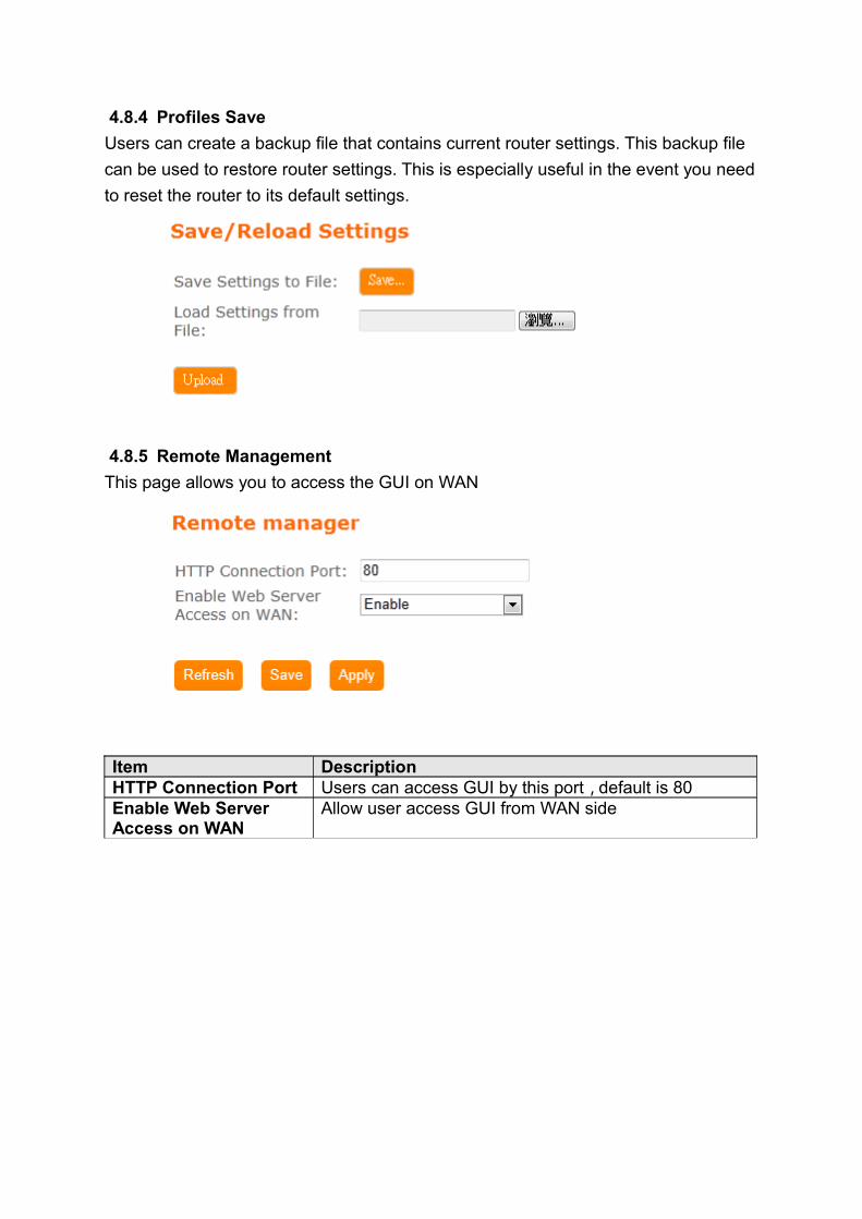
4.8.4 Profiles Save
Users can create a backup file that contains current router settings. This backup file
can be used to restore router settings. This is especially useful in the event you need
to reset the router to its default settings.
4.8.5 Remote Management
This page allows you to access the GUI on WAN
Item DescriptionHTTP Connection Port Users can access GUI by this port,default is 80Enable Web Server Access on WAN
Allow user access GUI from WAN side
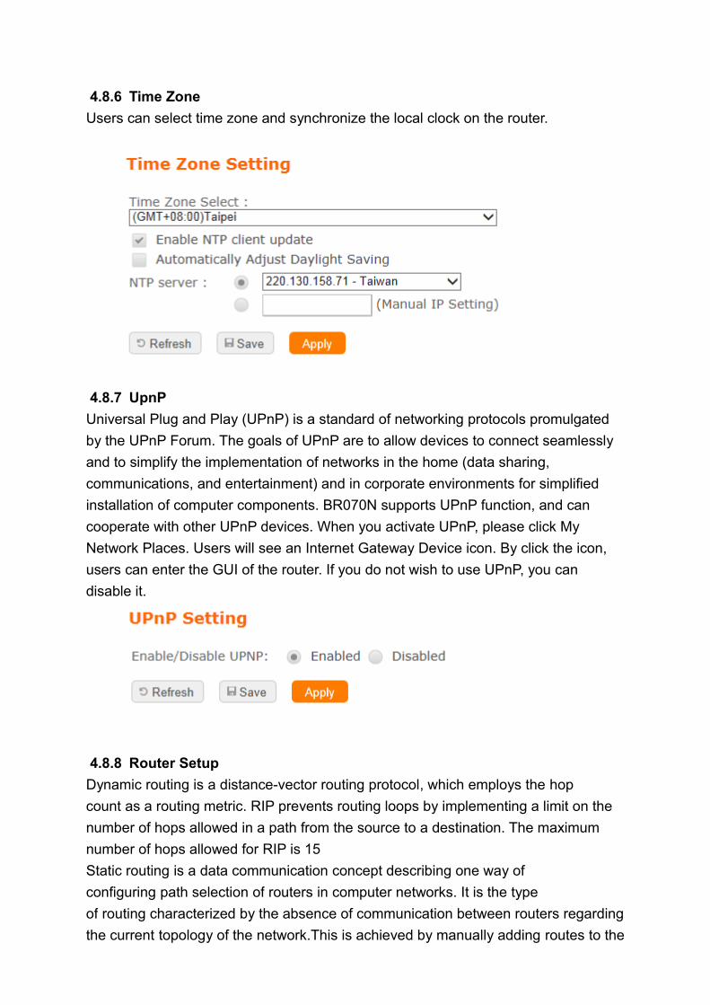
4.8.6 Time Zone
Users can select time zone and synchronize the local clock on the router.
4.8.7 UpnP
Universal Plug and Play (UPnP) is a standard of networking protocols promulgated
by the UPnP Forum. The goals of UPnP are to allow devices to connect seamlessly
and to simplify the implementation of networks in the home (data sharing,
communications, and entertainment) and in corporate environments for simplified
installation of computer components. BR070N supports UPnP function, and can
cooperate with other UPnP devices. When you activate UPnP, please click My
Network Places. Users will see an Internet Gateway Device icon. By click the icon,
users can enter the GUI of the router. If you do not wish to use UPnP, you can
disable it.
4.8.8 Router Setup
Dynamic routing is a distance-vector routing protocol, which employs the hop
count as a routing metric. RIP prevents routing loops by implementing a limit on the
number of hops allowed in a path from the source to a destination. The maximum
number of hops allowed for RIP is 15
Static routing is a data communication concept describing one way of
configuring path selection of routers in computer networks. It is the type
of routing characterized by the absence of communication between routers regarding
the current topology of the network.This is achieved by manually adding routes to the
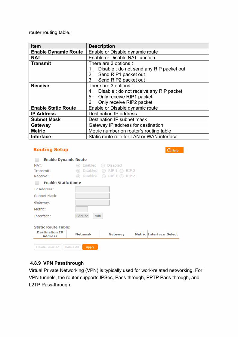
router routing table.
Item DescriptionEnable Dynamic Route Enable or Disable dynamic routeNAT Enable or Disable NAT functionTransmit There are 3 options:
1. Disable:do not send any RIP packet out2. Send RIP1 packet out3. Send RIP2 packet out
Receive There are 3 options:4. Disable:do not receive any RIP packet5. Only receive RIP1 packet6. Only receive RIP2 packet
Enable Static Route Enable or Disable dynamic routeIP Address Destination IP addressSubnet Mask Destination IP subnet maskGateway Gateway IP address for destinationMetric Metric number on router’s routing tableInterface Static route rule for LAN or WAN interface
4.8.9 VPN Passthrough
Virtual Private Networking (VPN) is typically used for work-related networking. For
VPN tunnels, the router supports IPSec, Pass-through, PPTP Pass-through, and
L2TP Pass-through.
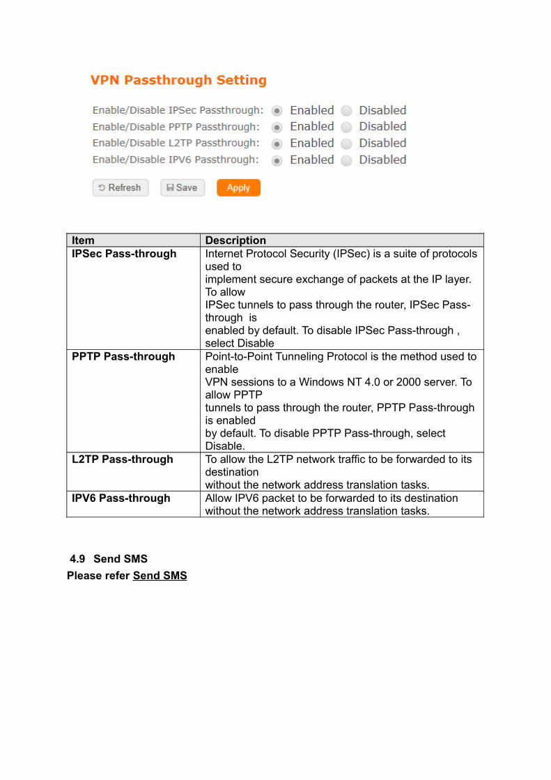
Item DescriptionIPSec Pass-through Internet Protocol Security (IPSec) is a suite of protocols
used to implement secure exchange of packets at the IP layer. To allow IPSec tunnels to pass through the router, IPSec Pass-through is enabled by default. To disable IPSec Pass-through , select Disable
PPTP Pass-through Point-to-Point Tunneling Protocol is the method used to enable VPN sessions to a Windows NT 4.0 or 2000 server. To allow PPTP tunnels to pass through the router, PPTP Pass-through is enabled by default. To disable PPTP Pass-through, select Disable.
L2TP Pass-through To allow the L2TP network traffic to be forwarded to its destination without the network address translation tasks.
IPV6 Pass-through Allow IPV6 packet to be forwarded to its destination without the network address translation tasks.
4.9 Send SMS
Please refer Send SMS
5 Q & A
5.1 Installation
• Where is the XDSL Router installed on the network?A:In a typical environment, the Router is installed between the XDSL line and the LAN. Plug the XDSL Router into the XDSL line on the wall and Ethernet port on the Hub (switch or computer).
• Why does the throughput seem slow?A:To achieve maximum throughput, verify that your cable doesn’t exceed 100 meter. If you have to do so, we advise you to purchase a bridge to place it in the middle of the route in order to keep the quality of transmitting signal. Out of this condition you would better test something else.
◦ Verify network traffic does not exceed 37% of bandwidth.◦ Check to see that the network does not exceed 10 broadcast messages
per second. ◦ Verify network topology and configuration.
5.2 LED
• Why doesn’t BRB73n power up?A:Check if the output voltage is suitable, or check if the power supply is out of order.
• The Internet browser still cannot find or connect to BRB73n after verifying the IP address and LAN cable, the changes cannot be made, or password is lost.A:In case BRB73n is inaccessible; you can try to restore its factory default settings. Please press the “Reset” button and keep it pressed for over 7 seconds and the light of STATUS will vanish. The LEDs will flash again when reset is successful.
• Why does BRB73n shut down unexpectedly?A:Re-plug your power adapter. Then, check the STATUS indicator; if it is off, the internal flash memory is damaged. For more help, please contact with your provider.
5.3 Installation
• What is the default IP address of the router for LAN port?A:The default IP address is 192.168.1.1 with subnet mask 255.255.255.0
• I don't know my WAN IP.A:There are two ways to know.Way 1:Check with your Internet Service Provider. Way 2:Check the setting screen of BRB73n . Click on Status & Log item to
select Network Configuration on the Main Menu. WAN IP is shown on the WAN interface.
• How can I check whether I have static WAN IP Address?A:Consult your ISP to confirm the information, or check Network Configuration in BRB73n ’s Main Menu.
• Will the Router allow me to use my own public IPs and Domain, or do I have
to use the IPs provided by the Router?A:Yes, the Router mode allows for customization of your public IPs and Domain.
5.4 OS Setting
• Why can’t my computer work online after connecting to BRB73n ?A: It’s possible that your Internet protocol (TCP/IP) was set to use the following IP address. Please do as the following steps. (Windows 2000 & XP) Start>Settings>Network and Dial-up Connections>double click on Internet Protocol(TCP/IP)>select obtain IP address automatically >Click on OK button. Then, open Internet browser for testing. If you still can’t go online, please test something else below.
◦ Verify network configuration by ensuring that there are no duplicate IP addresses.
◦ Power down the device in question and ping the assigned IP address of the device. Ensure no other device responds to that address.
◦ Check that the cables and connectors or use another LAN cable.
• Why can't I connect to the router's configuration utility?A:Possible Solution 1: Make sure that your Ethernet connect properly and securely. Make sure that you've plugged in the power cord. Possible Solution 2: Make sure that your PC is using an IP address within the range of 192.168.1.2 to 192.168.1.254. Make sure that the address of the subnet mask is 255.255.255.0. If necessary, the Default Gateway data should be at 192.168.1.1. To verify these settings, perform the following steps:
Windows 2000, or XP Users:◦ Click on Windows Start > click on Run > input cmd > click on OK
button.◦ At the DOS prompt, type ipconfig/all.◦ Check the IP Address, Subnet Mask, Default Gateway data. Is this
data correct? If the data isn't correct. Please input ipconfig/release > press Enter > input ipconfig/renew > press Enter.
Possible Solution 3: Verify the connection setting of your Web browser and verify that the HTTP Proxy feature of your Web browser is disabled. Make these verifications so that your Web browser can read configuration pages inside your router. Launch your Web browser.
Internet Explorer Users:◦ Click on Tools > Internet Options > Connections tab.◦ Select never dial a connection, click on Apply button, and then click on
OK button.◦ Click on Tools and then click on Internet Options.◦ Click on Connections and then click on LAN Settings.◦ Make sure none of the check boxes are selected and click on OK
button.◦ Click on OK button.
Netscape Navigator Users:◦ Click on Edit > Preferences > double-click Advanced in the Category
window.◦ Click on Proxies > select Direct connection to the Internet > click on OK
button.◦ Click on Edit again and then click on Preferences.◦ Under category, double-click on Advanced and then click on Proxies.◦ Select Direct connection to the Internet and click on OK button.◦ Click on OK button.
• Web page hangs, corrupt downloads, or nothing but junk characters is being displayed on the screen. What do I need to do?A:Force your NIC to 10Mbps or half duplex mode, and turn off the "Auto-negotiate" feature of your NIC as a temporary measure. (Please look at the Network Control Panel, in your Ethernet Adapter's Advanced Properties tab.)
• Why can't I connect to the Web Configuration?A:you can remove the proxy server settings in your web browser.
5.5 BRB73n Setup
• Why does BRB73n ’s setup page shut down unexpectedly?A:If one of the pages appears incompletely in BRB73n ’s setup pages, please click on Logout item on the Main Menu before shutting it down. Don’t keep it working. Then, close Internet browser and open it again for going back to the previous page.
• I don’t know how to configure DHCP.A:DHCP is commonly used in the large local network. It allows you to manage and distribute IP addresses from 2 to 254 throughout your local network via BRB73n . Without DHCP, you would have to configure each computer separately. It’s very troublesome. Please Open Internet browser > Input 192.168.1.1 in the website blank field > Select DHCP Server under the IP Config Menu. For more information, please refer to Router Mode or AP Mode).
• How do I upgrade the firmware of BRB73n ?A:Periodically, a new Flash Code is available for BRB73n on your product supplier’s website. Ideally, you should update BRB73n ’s Flash Code using Firmware Upgrade on the System Management menu of BRB73n Settings.
• Why is that I can ping to outside hosts, but cannot access Internet websites?A:Check the DNS server settings on your PC. You should get the DNS servers settings from your ISP. If your PC is running a DHCP client, remove any DNS IP address setting. As the router assign the DNS settings to the DHCP-client-enabled PC.
• BRB73n couldn’t save the setting after click on Apply button?A:BRB73n will start to run after the setting finished applying, but the setting isn’t written into memory. Here we suggest if you want to make sure the setting would be written into memory, please reboot the device via Reboot under System Management directory.
5.6 Wireless LAN
• Why couldn’t my wireless notebook work on-line after checking? A:Generally, Wireless networks can sometimes be very complicated to set up, particularly if you're dealing with encryption and products from different vendors. Any number of variables can keep your workstations from talking to each other. Let's go over some of more common ones. For starters, verify that your router and your workstation are using the same SSID descriptions. SSID acts as a password when a mobile device tries to connect to the wireless network. The SSID also differentiates one WLAN from another, so all access points and all devices attempting to connect to a specific WLAN must use the same SSID. A workstation will not be permitted to connect to the network unless it can provide this unique identifier. This is similar to the function of your network's Workgroup or Domain name. When you're experiencing conductivity problems, it is always best to keep things simple. So next you are going to do is that, please disable any WEP encryption you might have configured. Successful implementation of encryption also includes the use of a shared key. A HEX key is the most common, but other formats are also used. This key identifies the workstation to the router as a trusted member of this network. Different manufacturers can implement this key technology in ways that might prevent them from working correctly with another vendor's products. So pay attention to detail is going to be the key to a successful installation. Next make sure the router and the NIC are configured to use the same communications channel. There are normally 11 of them, and the default channel can also vary from vendor to vendor. You might also want to confirm that the router has DHCP services enabled and an address pool configured. If not, the NIC won't be able to pick up an IP address. I have run across a few access points that offer DHCP services but do not assign all of the needed IP information to the NIC. As a result, I was able to connect to the network, but could not browse the web. The point is, don't assume anything. Verify for yourself that all of the required settings are being received by the workstation. Finally, you might want to keep the system you're trying to configure in the same room as the router, at least during the initial configuration, in order to minimize potential interference from concrete walls or steel beams.
• My PC can’t locate the Wireless Access Point.A:Check the following:
◦ Your PC is set to Infrastructure Mode. (Access Points are always in Infrastructure Mode.)
◦ The SSID on your PC and the Wireless Access Point are the same. Remember that the SSID is case-sensitive. So, for example “Workgroup” does NOT match “workgroup”.
◦ Both your PC and the Wireless Access Point must have the same setting for WEP. The default setting for the Wireless Router is disabled, so your wireless station should also have WEP disabled.
◦ If WEP is enabled on the Wireless Router, your PC must have WEP enabled, and the key must match.
◦ If the Wireless Router’s Wireless screen is set to Allow LAN access to selected Wireless Stations only, then each of your Wireless stations must have been selected, or access will be blocked.
◦ To see if radio interference is causing a problem, see if connection is possible when close to the Wireless Access Point. Remember that the connection range can be as little as 100 feet in poor environments.
• Wireless connection speed is very slow.A: The wireless system will connect at highest possible speed, depending on the distance and the environment. To obtain the highest possible connection speed, you can experiment with following:
◦ Access Point location: Try adjusting the location and orientation of the Access Point.
◦ Wireless Channel: If interference is the problem, changing to another channel may show a marked improvement.
◦ Radio Interference: Other devices may be causing interference. You can experiment by switching other devices off, and see if this helps. Any “noisy” devices should be shielded or relocated.
◦ RF Shielding: Your environment may tend to block transmission between the wireless stations. This will mean high access speed is only possible when close to the Access Point.
• Some applications do not run properly when using the Wireless Router.A:The Wireless Router processes the data passing through it, so it is not transparent. Use the Special Application feature to allow the use of Internet applications which do not function correctly. If this does solve the problem, you can use the DMZ function. This should work with almost every application, but:
◦ It is a security risk, since the firewall is disabled.◦ Only one (1) PC can use this feature.
• I can’t connect to the Wireless Router to configure it.A:Check the following:
◦ The Wireless Router is properly installed, LAN connections are OK, and it is powered ON.
◦ Make sure that your PC and the Wireless Router are on the same network segment.
◦ If your PC is set to “Obtain an IP Address automatically” (DHCP client), restart it.
◦ If your PC uses a Fixed (Static) IP address, make sure that it is using an IP Address within the range 192.168.1.129 to 192.168.1.253 and thus compatible with the Wireless Router’s default IP Address of 192.168.1.254. Also, the Network Mask should be set to 255.255.255.0 to match the Wireless Router. In Windows, you can check these settings by using Control Panel ~ Network to check the Properties for the TCP/IP protocol.
• The WinXP wireless interface couldn’t communicate the WEP with SAPIDO BRB73n’s wireless interface.
A:The default WEP of WinXP is Authentication Open System - WEP, but the WEP of SAPIDO BRB73n is only for Shared Key - WEP, it caused both sides couldn’t communicate. Please select the WEP of WinXP from Authentication Open System to Pre-shared Key - WEP, and then the WEP wireless interface between WinXP and SAPIDO BRB73n would be communicated.
5.1 Support• What is the maximum number of IP addresses that the XDSL Router will
support?A:The Router will support to 253 IP addresses with NAT mode.
• Is the Router cross-platform compatible?A:Any platform that supports Ethernet and TCP/IP is compatible with the Router.
5.2 Others• Why does the router dial out for PPPoE mode very often?
A:Normally some of game, music or anti-virus program will send out packets that trigger the router to dial out, you can close these programs. Or you can set the idle time to 0, then control to dial out manually.
• What can I do if there is already a DHCP server in LAN?A:If there are two DHCP servers existing on the same network, it may cause conflict and generate trouble. In this situation, we suggest to disable DHCP server in router and configure your PC manually.
6 Appendices6.1 Operating Systems
• Microsoft:Windows 2000, XP, Vista, Windows 7. • Apple:Mac OS X 10.4.7, Leopard and the following related versions.• Linux:Redhat 9, Fedora 6 & 7, Ubuntu 7.04 and the following related
versions.
6.2 Browsers• Internet Explorer ver. 6 and 7 and the following related versions.• FireFox ver. 2.0.0.11 and the following related versions.3. • Safari ver. 3.04 and the following related versions.
6.3 Communications Regulation Information
Should any consumers need to learn more information, services and supports, please
contact the supplier of your product directly.