Embed Size (px)
Citation preview

FATIGUE STRENGTH ENHANCEMENT BY MEANS OF WELD DESIGN CHANGE AND THE APPLICATION OF
ULTRASONIC IMPACT TREATMENT
BY
John W Fisher ATLSS Engineering Research Center, Lehigh University
Efim Statnikov
Applied Ultrasonics, Birmingham AL
Lionel Tehini Applied Ultrasonics, Birmingham AL
ABSTRACT
Over the past four years extensive research has been done in the area of fatigue enhancement of fracture critical details on bridges. This includes the aspect of evaluating different weld designs and post weld treatment approaches. With the development of high strength steels and their use within the bridge industry further emphasis has been placed on this research. Fatigue tests have been conducted on samples manufactured from high strength steel supplied from two different international steel manufacturers, Swedish Steel and Nippon Steel Corporation. During this time full size girders manufactured using HPS-70W and full size rolled-web girders using HPS-60W, with welded A588 steel attachments (stiffeners and cover plates), have been tested at Lehigh University. This presentation serves to report the results to date of these studies and provide some insight into the conclusions drawn in consideration of fatigue fracture details on bridge girders. Specific emphasis will be focused on weld design options and the benefits achieved by ultrasonic impact treatment. The study covered areas of new welded structures as well as repair procedures and fatigue improvement techniques. The presentation addresses recommended procedures to be considered in the design and manufacture of new bridge members, as well as specific field applications for retrofit treatment conducted on bridges currently in use. This system wide approach to fatigue enhancement and consideration of weld design during bridge manufacturing covers areas of significant concern to design engineers and bridge maintenance engineers. With this paper we hope to prove that the combination of new weld design and ultrasonic impact treatment eliminates fatigue as a concern in design.

INTRODUCTION
The fatigue strength of components with various as-welded details has been studied for decades [1, 2, 3]. Design S-N curves exist in most structural codes wherein the fatigue resistance of welded joints has been defined as a function of detail type and stress range. In this classification system, welded attachments can limit the serviceability limit state. To avoid unacceptable limits on the design capacity it is desirable to enhance the fatigue resistance of common attachment details such as transverse stiffeners, cover plates, gusset plates and other welded details that experience crack growth from a weld toe and have their resistance defined by AASHTO Categories C, D, E or E's. Enhancement of fatigue resistance of welded joints by plastic deformation of the surface and by improvement of weld toe characteristics is well established. It is known that the conventional improvement techniques such as grinding, shot peening, air hammer peening, gas tungsten arc (TIG) re-melting and welding consumables with improved weld toe characteristics can improve fatigue resistance of welded details [4]. However, these procedures are manpower intensive, not always efficient and less environmentally friendly. The relatively new technique of ultrasonic impact treatment of the weld toe offers an alternative means to rationally deal with these issues. Ultrasonic Impact Treatment (UIT) was originally invented by Dr Efim Statnikov in the Soviet Union for use on naval ships to reduce welding stresses and deformations and introduce compressive stresses [5, 6]. Other peening techniques, e.g. hammer and needle peening, operate at relatively low frequencies, typically in the range 50 to 100 Hz, causing the tool to move in an unsteady manner, necessitating considerable effort to keep the tool aligned on the weld toe line. The high levels of vibration and noise make the peening methods uncomfortable, and prolonged use may pose health risks to the operator, similar to other tools with high vibration levels. In contrast the UIT method operates at a very high frequency, approximately 27 kHz, and the noise and vibration is much lower. The ease of use of the UIT method may result in considerable benefits in terms of quality of the treatment compared with conventional peening methods. The objective of the treatment is to introduce beneficial compressive residual stresses at the treated weld toe zones and to reduce stress concentration by improving the weld toe profile. The UIT equipment is shown in Fig. 1. The equipment comprises a handheld tool and an electronic control box. The tool is easy to handle during application compared with conventional air hammer peening equipment, and its use is easily taught. The frequency of the head movement is indicated to be close to 27,000 Hz. The noise is negligible compared to that of other peening devices. Several kinds of heads and tips are available and can be chosen on the basis of the surface condition of the weld details to be treated.
Figure 1
BACKGROUND
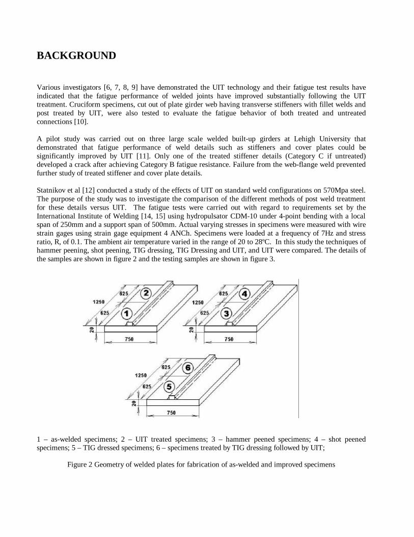
Various investigators [6, 7, 8, 9] have demonstrated the UIT technology and their fatigue test results have indicated that the fatigue performance of welded joints have improved substantially following the UIT treatment. Cruciform specimens, cut out of plate girder web having transverse stiffeners with fillet welds and post treated by UIT, were also tested to evaluate the fatigue behavior of both treated and untreated connections [10]. A pilot study was carried out on three large scale welded built-up girders at Lehigh University that demonstrated that fatigue performance of weld details such as stiffeners and cover plates could be significantly improved by UIT [11]. Only one of the treated stiffener details (Category C if untreated) developed a crack after achieving Category B fatigue resistance. Failure from the web-flange weld prevented further study of treated stiffener and cover plate details. Statnikov et al [12] conducted a study of the effects of UIT on standard weld configurations on 570Mpa steel. The purpose of the study was to investigate the comparison of the different methods of post weld treatment for these details versus UIT. The fatigue tests were carried out with regard to requirements set by the International Institute of Welding [14, 15] using hydropulsator CDM-10 under 4-point bending with a local span of 250mm and a support span of 500mm. Actual varying stresses in specimens were measured with wire strain gages using strain gage equipment 4 ANCh. Specimens were loaded at a frequency of 7Hz and stress ratio, R, of 0.1. The ambient air temperature varied in the range of 20 to 28ºC. In this study the techniques of hammer peening, shot peening, TIG dressing, TIG Dressing and UIT, and UIT were compared. The details of the samples are shown in figure 2 and the testing samples are shown in figure 3.
1 – as-welded specimens; 2 – UIT treated specimens; 3 – hammer peened specimens; 4 – shot peened specimens; 5 – TIG dressed specimens; 6 – specimens treated by TIG dressing followed by UIT;
Figure 2 Geometry of welded plates for fabrication of as-welded and improved specimens
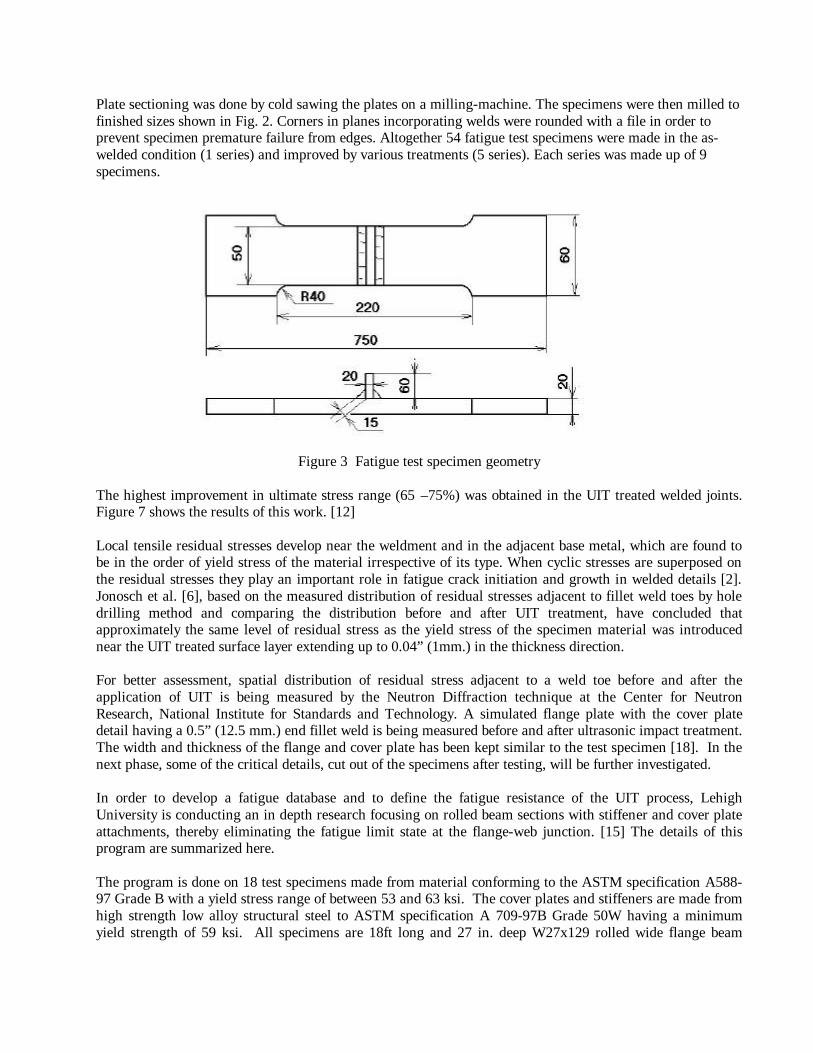
Plate sectioning was done by cold sawing the plates on a milling-machine. The specimens were then milled to finished sizes shown in Fig. 2. Corners in planes incorporating welds were rounded with a file in order to prevent specimen premature failure from edges. Altogether 54 fatigue test specimens were made in the as-welded condition (1 series) and improved by various treatments (5 series). Each series was made up of 9 specimens.
Figure 3 Fatigue test specimen geometry The highest improvement in ultimate stress range (65 –75%) was obtained in the UIT treated welded joints. Figure 7 shows the results of this work. [12] Local tensile residual stresses develop near the weldment and in the adjacent base metal, which are found to be in the order of yield stress of the material irrespective of its type. When cyclic stresses are superposed on the residual stresses they play an important role in fatigue crack initiation and growth in welded details [2]. Jonosch et al. [6], based on the measured distribution of residual stresses adjacent to fillet weld toes by hole drilling method and comparing the distribution before and after UIT treatment, have concluded that approximately the same level of residual stress as the yield stress of the specimen material was introduced near the UIT treated surface layer extending up to 0.04” (1mm.) in the thickness direction. For better assessment, spatial distribution of residual stress adjacent to a weld toe before and after the application of UIT is being measured by the Neutron Diffraction technique at the Center for Neutron Research, National Institute for Standards and Technology. A simulated flange plate with the cover plate detail having a 0.5” (12.5 mm.) end fillet weld is being measured before and after ultrasonic impact treatment. The width and thickness of the flange and cover plate has been kept similar to the test specimen [18]. In the next phase, some of the critical details, cut out of the specimens after testing, will be further investigated. In order to develop a fatigue database and to define the fatigue resistance of the UIT process, Lehigh University is conducting an in depth research focusing on rolled beam sections with stiffener and cover plate attachments, thereby eliminating the fatigue limit state at the flange-web junction. [15] The details of this program are summarized here. The program is done on 18 test specimens made from material conforming to the ASTM specification A588-97 Grade B with a yield stress range of between 53 and 63 ksi. The cover plates and stiffeners are made from high strength low alloy structural steel to ASTM specification A 709-97B Grade 50W having a minimum yield strength of 59 ksi. All specimens are 18ft long and 27 in. deep W27x129 rolled wide flange beam

sections. The thickness of the flanges and the cover plates are 1.1” and 1” respectively, whereas the web and transverse stiffeners are 0.61” and 0.5” thick. The specimens were fabricated by a local bridge fabricator according to the AWS specification. Transverse stiffeners over the full depth of the girder were provided symmetrically about the centerline on either side. The stiffeners were welded at the top and bottom flange and the web. The welded area considered critical for this study was the welded details at the junction of the transverse stiffener and the bottom flange and at the lower potion of the junction between the stiffener and the web. According to the AASHTO specification this detail is classified as Category C. Cover plates were provided on either ends of the girder for a length of 4.67 ft. One of the cover plates was welded all around to the flange with a 0.5” fillet weld (on seven of the specimens.) In two of the specimens the second cover plate does not have any end weld. Both cover plates on the remaining twelve specimens has approximately 1” fillet end welds. Smooth transitions between the two weld sizes were used to reduce any stress concentration. All end welds of the cover plate are considered critical and are classified as Category E’ according to the AASHTO standards. The critical details were all treated by the UIT tool according to the manufacturers procedure document for these details [16]. The treatment was carried out using multiple passes and 3mm diameter pins. On average 3 passes were done at each weld to ensure a smooth transition between the weld toe and the base material. All the tests are conducted at constant amplitude fatigue loading. The test beams were inspected and the stress range monitored and recorded periodically. Inspection for fatigue cracks is made visually with the aid of a magnifying glass. In the case of web cracks, the test is temporarily stopped and a hole is drilled at the crack tip to arrest the crack growth. The test is then continued further. The aim is to have at least one fatigue crack in each of the critical details in each specimen. The girders tested so far have only failed by cracking and fracture of the tension flange at the end of cover plates with 0.5”. (12.5 mm.) end welds. These cracks have initiated either at the weld toe or at the root of the smaller size end weld. The test results demonstrate that one treated cover plate detail achieved Category D resistance, whereas the other two details exceeded the category B resistance curve (see Fig’s. 8 & 9) None of the critical stiffener details has developed detectable cracks in the test program to date. The stiffener test data exceeded the Category A resistance curve (Fig. 10). To date, only one UIT treated stiffener detail has developed a crack. [11]. This detail exceeded the category B fatigue resistance as illustrated in Fig. 10. The test data for the details treated by UIT are plotted in Figs. 8, 9 and 10 along with the results of previous research [17]. Data from all the UIT details have indicated a significantly longer life compared to untreated details. To obtain fatigue data from the stiffeners and cover plates with large end welds on the test girders subjected to 6.5 to 7.8 million cycles, an innovative scheme has been envisaged. Since the test specimens have failed only from cracks that initiated at the smaller end weld of the cover plate, a test specimen was fabricated by splicing cut pieces from the two specimens that have been tested under the same stress range and have undergone comparable number of stress cycles. The modified specimen will have approximately 1”. (25mm.) end welds at the ends of the two cover plates. It is expected that the test of the specimen will provide additional fatigue data for the stiffeners and the cover plated details that have not failed in the normal course of testing.

BRIDGE FIELD APPLICATION
Introduction Fatigue cracking was being experienced on four bridges on Interstate 66. All four bridges were built in 1979. The fatigue cracks occurred at the end of the fillet welds (connection plate weld to the web) at the top of the connection plates where the connection plate is not positively connected to the flange. Also, the connection plates for the diaphragms are cut short of the bottom flange a distance of 4tw to 6tw. Some of the particulars concerning each bridge are:
Structure No. A B C D Year Built 1979 1979 1979 1979 Br. Length 288' 288' 286' 312' Max Span 105' 105' 118' 118' No. Spans 3 3 3 3 Skew-degree 58 53 35 36 No. Diaphragms 68 63 47 52 No. Con. Pl. 136 126 94 104 No. Cracks 35 23 8 21
Structures C and D have one end span that has rolled beams with cover plates instead of plate girders. Due to the fatigue cracking at the top of the connection plates, it was decided to retrofit the top of the connection plates. In doing so concern was raised about the effect at the bottom of the connection plate due to the change in design. For this reason it was decided to also retrofit the bottom of the connection plates before fatigue cracking initiated at the end of the welds of the connection plates to the webs. At the same time it was decided to retrofit the cover plates while they had a contractor doing work on the connector plates. The Solution Two alternatives were investigated – the conventional retrofit and ultrasonic impact treatment (UIT). Some of the considerations for using a conventional retrofit technique were as follows:
1. The conventional retrofit of the connector plate would require bolting an angle or tee to the bottom tension flange and connector plate to make a positive connection. This required field drilling two 7/8" diameter holes in the flange and possibly two in the connector plate if existing holes could not be used.
2. Since the connection plates were a tight fit to the top compression flanges, the district engineers looked at welding the connection plates to the compression flanges.
3. For the cover plate retrofit, a splice plate detail that required field drilling of 12 to 16 - 7/8" diameter holes was considered.
4. The time required to complete conventional retrofit details can vary from 1.5 hours per connection plate with angle retrofit to 4 or 5 hours per cover plate for the cover plate retrofit.
5. The complexity and time required for doing the work made this alternative very expensive.

In comparison ultrasonic impact treatment offered the following benefits:
1. UIT introduces compressive stress across the surface to which it is being applied and creates a uniform residual stress profile across the weld heat affected zone.
2. The ultrasonic impact treatment could be applied in minutes (figure 4) and did not require the traffic across the bridge to be altered other than for access purposes.
3. These benefits offered substantial timesavings and reduced traffic disruptions. 4. The cost of doing the above treatments per stiffener detail (figure 6) and cover plate (figure 5)
was considerably less than the costs for doing the conventional retrofit. . Due to the above considerations the decision was made to weld the connection plates to the compression flanges and use UIT to treat the weld details at the bottom of the diaphragm connection plates and ends of the cover plates. Weld details were UIT treated for 3" plus on each side of the connector plates and around the end of the connector plates at the bottom of the diaphragm. The end of the cover plate were UIT treated for a 6" length on each side of cover plate and across the entire end of the cover plate. All weld details were treated at the weld toe as depicted in figures 5 and 6 below.
Figure 4 Figure 5 Figure 6
CONCLUSION
1. The data shows that UIT technique is a superior alternative to conventional post weld treatment techniques such as air hammer peening or gas tungsten arc re-melting.
2. The results of the studies done to date show that the UIT technique successfully enhanced the fatigue
strength of all welded details tested.
3. The results on the girder test program demonstrated that the through the use of UIT the Category E’ cover plate weld details can achieve Category C or better fatigue strength. The Category C transverse stiffener details on the tension flange and web can achieve Category B fatigue resistance or better.
4. UIT is an effective means of improving the fatigue life of bridges not only in new manufacture but in
maintenance and repair procedures.
5. UIT is an economically viable solution for use in the retrofit and maintenance of bridges.

Linear regression :
Series 1 – as welded (m = -5.6867); Series 2 – UIT treated (m = -17.5413), 5 and 3mm pin diameter; Series 3 – hammer peened (m = -8.3701); Series 4 – shot peened (m = -8.1321); Series 5 – TIG dressed (m = -6.5539); Series 6 – TIG dressed and UIT treated (m = -6.2090); Series 7 – UIT treated (m = -9.7799), additional series, 3mm pin diameter.
Series No. Results of approximation ? ? ?
?N=2000000 cycles), MPa After treatment increase of ? ? ,
% 1 lgN=19.3650-5.6867*lg? ? 198 - 2 lgN=50.4231-17.5413*lg? ? 328 65 3 lgN=26.7702-8.3701*lg? ? 279 41 4 lgN=26.2096-8.1321*lg? ? 281 42 5 lgN=22.4068-6.5539*lg? ? 287 44 6 lgN=19.3650-6.2090*lg? ? 293 51 7 lgN=31.0829-9.7799*lg? ? 342 73
Figure. 7 Fatigue curves for welded joints in the as-welded and improved conditions [12]
N, cycles1e+4 1e+5 1e+6
? ? , MPa
200
250
300
350
400
450
1
3
4
6
2
5 7

Figure. 8 UIT enhanced details compared with as-welded details at end of cover plates
0.5” end welds
12.5 mm end weld (0.5tcp);

Figure. 9 UIT enhanced details compared with as-welded details at end of cover plates
1” end welds
Approximately 25.4 mm end weld (1.0tcp)

Figure 10. UIT enhanced details compared with as-welded details at stiffeners.
Two pairs of back-to-back stiffeners

? ? W27x129 rolled section ASTM A 709 GR 50W ? ? Yield stress 365 to 435 MPa ? ? 5.486 m long and 686 mm deep; effective span 5.181 m ? ? Transverse stiffeners symmetrically at 457 mm ? ? Cover plates extending 1.423 m from ends
Figure 11 Full Size Girder Specimens

REFERENCES 1. Fisher, JW, Frank, KH, Hirt, MA, and McNamee, BM (1970). “Effect of the Fatigue Strength of Steel
Beams”, NCRP Report 102, Highway Research Board, Washington DC.
2. Fisher, JW, Albrecht, PA, Yen, BT, Klingerman, DJ and McNamee, BM (1974). Fatigue Strength of Steel Beams with Transverse Stiffeners and Attachments”, NCHRP Report 147, Highway Research Board, Washington DC.
3. Gurney, TR, and Maddox, SJ (1971). “A Re-analysis of Fatigue Data for Welded Joints in Steel”, The
Welding Institute Report R/RB/E44/7 1, Abington Hall, Abington, Cambridge, UK.
4. Fisher, JW, Hausammann, H, Sullivan, MD, and Pense, AW (1979). “Detection and Repair of Fatigue Damage in Welded Highway Bridges”, NCHRP Report 206, Transportation Research Board, Washington DC.
5. Lopez-Martinez M, et al., Fatigue behaviour of steels with strength levels beteen 350 and 900 MPa. -
Influence of post-weld treatments under spectrum loading. Paper D in Fatigue Behaviour of Welded High-Strength Steels, Report No. 97-30, Royal Institute of Technology, Stockholm, Oct. 1997.
6. Janosch, JJ, Koneczny, H, Debiez, S, Statnikov, EC, Troufiakov, VJ, and Mikee, PP (1995).
“Improvement of Fatigue Strength in Welded Joint (in HSS and in Aluminum Alloy) by Applied Ultrasonic Hammer Peening”, IIW, Doc XIII-1594-95.
7. Haagensen, PJ, et al. (1998). “Introductory Fatigue Tests on Welded Joint in High Strength Steel and
aluminum Improved by Various Methods Including Ultrasonic Impact Treatment (UIT)”, IIW, Doc. XIII-1748-98.
8. Statnikov, Esh (1997). “Applications of Operational Ultrasonic Impact Treatment (UIT) Technologies in Production of Welded Joints”, IIW/IIS, Doc.XII-1667-97.
9. Statnikov, Esh (1997). “Comparison of Post Weld Deformation Methods for increase in Fatigue
Strength of Welded Joints”, IIW/IIS, Doc.XIII-1668-97.
10. Wright, W (1996). “Post-Weld Treatment of A Welded Bridge Girder by Ultrasonic Hammer Peening”, FHWA, Turner-Fairbanks test report, 9/29/96.
11. Takamori, H, and Fisher, JW (2000). “Tests of Large Girders Treated to Enhance Fatigue
Strength”, Transportation Research Record 1696, Transportation Research Board
12. Statnikov, E, Muktepavel, V, Trufyakov, V, Mikheev, P, Kuzmenko, A and Blomqvist, A (2000). “Efficiency Evaluation of Ultrasonic Impact Treatment (UIT) of Welded Joints in Weldox 420 Steel in accordance with the IIW Program”, IIW/IIS Doc XIII – 1817 – 00.
13. Lieurade H.P., “Fatigue testing of Welded Components,” IIW Doc. XIII-1516, revision 2, May 1995
14. . Haagensen P.J., “IIW Collaborative Test Program on Improvement Methods,” IIW Doc. XIII-WG2-
30, August 1994.

15. (Replace this with the ISOPE paper. Then cite the June Progress report which will include the three Figures that we will send youRoy, S., Fisher, J., and Yen, B. “Fatigue Resistance of Welded Detail Enhancement by Ultrasonic Impact Treatment.” Progress report for FHWA April 2001.
16. Applied Ultrasonics (2000). “Technical Procedure Document”, Esonix Ultrasonic Impact Treatment,
Applied Ultrasonics, Birmingham, AL, USA
17. Keating, P, and Fisher JW (1986). “Evaluation of Fatigue Tests and Design Criteria on Welded Details”, NCHRP Report 286, Transportation Research Board, Washington DC.
18. Prask, H.J., Gnaupel-Herold,T., Fisher, J.W., Cheng,X., “Residual Stress Modification by means of
Ultrasonic Impact Treatment”, Proceedings, Society for Experimental Mechanics, Portland, Or, June 2001