Embed Size (px)
Citation preview

Accepted Manuscript
Fatigue behaviour of AA6082-T6 MIG welded butt joints improved by friction
stir processing
J. da Silva, J.M. Costa, A. Loureiro, J.M. Ferreira
PII: S0261-3069(13)00341-5
DOI: http://dx.doi.org/10.1016/j.matdes.2013.04.026
Reference: JMAD 5362
To appear in: Materials and Design
Received Date: 6 November 2012
Accepted Date: 7 April 2013
Please cite this article as: da Silva, J., Costa, J.M., Loureiro, A., Ferreira, J.M., Fatigue behaviour of AA6082-T6
MIG welded butt joints improved by friction stir processing, Materials and Design (2013), doi: http://dx.doi.org/
10.1016/j.matdes.2013.04.026
This is a PDF file of an unedited manuscript that has been accepted for publication. As a service to our customers
we are providing this early version of the manuscript. The manuscript will undergo copyediting, typesetting, and
review of the resulting proof before it is published in its final form. Please note that during the production process
errors may be discovered which could affect the content, and all legal disclaimers that apply to the journal pertain.
1
FATIGUE BEHAVIOUR OF AA6082-T6 MIG WELDED BUTT JOINTS IMPROVED BY FRICTION
STIR PROCESSING
J. da Silva1, J.M. Costa1*, A. Loureiro1, J. M. Ferreira1
1 CEMUC, Mechanical Engineering Department,
University of Coimbra, Rua Luís Reis Santos, Pinhal de Marrocos, 3030-788, Coimbra, Portugal.
1Corresponding author. Tel.: +351239790754; Fax +351 239790701
E-mail address: [email protected] (J.M. Costa)
Abstract
Friction Stir Processing (FSP) was based on the principles of Friction Stir Welding (FSW), a solid-state
joining process originally developed for aluminium alloys. It is an emerging metalworking technique
which can provide localized modification and control of microstructures in near-surface layers of
processed metallic components. In this research, FSP appears as an alternative to traditional methods for
fatigue strength improvement of weld joints, such as re-melting, hammering and blasting,. This technique
was applied on Metal Inert Gas (MIG) butt welds with and without reinforcement, performed on AA
6082-T6 alloy plates. The potential benefits of post-processing MIG welds by FSP were studied using
microstructure analysis, hardness measurement, tensile strength, residual stress measurement, and fatigue
testing. Fatigue tests were carried out under constant amplitude loading with the stress ratio R set to 0.
Friction stir processing of MIG welds does not change the hardness and mechanical strength of the weld
substantially, but the fatigue strength was increased, due to the geometry modification in the weld toe,
reduction of weld defects and grain refinement of the microstructure.
Keywords: Fatigue strength, Friction stir processing, Metal inert gas welding, Aluminium alloy.
2
1. Introduction
The MIG welding process is largely used in joining metals, though it presents several drawbacks related
to porosity, hot cracking, strength reduction, distortion and residual stresses, particularly in welding
aluminium alloys. Porosity is a consequence of the hydrogen that is trapped during the process of
solidification. The lack of wetting can also occur in the toes of welds, due to insufficient heat input,
mishandling of the torch or inadequate cleaning of the oxides. Although the weld toes are critical zones in
terms of fatigue strength, due to stress concentration, the lack of wetting may not be particularly
detrimental if parallel to loading direction. Instead, porosity in this zone can be very detrimental if located
near the surface [1-2].
Friction stir welding (FSW) is a solid-state joining technique invented at the Welding Institute (TWI)
(Cambridge, United Kingdom), in 1991 [3], for welding soft materials such as aluminium alloys. From
the principles of the FSW technique, another process called Friction Stir Processing (FSP) was developed
(Mishra et al. [4]) for microstructure modification. This technology involves plunging a rapidly rotating
non-consumable tool, comprising a profiled pin and a larger diameter shoulder, into the surface and then
traversing the tool across the surface. FS processing provides microstructure refinement, densification and
homogeneity of welds in only one step. The final goal is the enhancement of specific properties through
the modification of localized microstructures. Moreover, the microstructure and mechanical properties of
the processed zone can be controlled by optimizing the tool design, FSP parameters and active
cooling/heating [5,6].
The mechanical properties and fatigue strength of AA6082 friction stir welds was analysed by some of
the present authors in a previous study [7]. The average hardness of thermo-mechanically affected zone of
welds, as well as their fatigue strength, was found to be lower than that of the base material. A
comparison with the data collected from the literature shows that FSW specimens present higher fatigue
strength than specimens welded by MIG or TIG processes, although they have significantly shorter lives
than the base material [8-9]. Furthermore, the characteristic curve obtained for Friction stir welds is
higher than the International Institute of Welding (IIW) fatigue class for fusion welds with full-
penetration two-sided butt joints. Another study performed by the same authors [10] analysed the validity
of Miners´s and Manson-Halford´s damage rules applied to FSW welded specimens under constant and
variable amplitude loadings with stress ratios R of 0 and -1. As expected, a significant mean stress
influence was observed. The comparison of experimental fatigue lives with predictions calculated using
both Miners´s and Manson-Halford´s Damage Rules revealed a good correlation for R=0. Under R=-1
both damage prediction methods were generally unconservative.
The aim of this research is to apply the FSP technique for grain refinement of the microstructure, the
removal of defects (such as porosity and lack of wetting), and possibly residual stress relaxation at the toe
3
of MIG butt welds, in order to improve their fatigue strength. Moreover, other properties intrinsically tied
to fatigue strength, such as hardness, yield stress and tensile strength are also analysed.
2. Experimental details
2.1. Base material
Aluminium alloy AA6082-T6 laminated plates 6 mm thick were used in this research. , The alloy was
solution heat treated at 530-550 ºC and then quenched to room temperature; the T6 condition was
obtained through artificial ageing at a temperature in the range of 170-200 ºC. The nominal chemical
composition of the alloy is given in Table 1[11] and the mechanical properties of the plates, evaluated in a
previous study [7], are shown in Table 2.
The microstructure of the aluminium alloy consists of “pancake type” grains with an average grain size of
135-150 µm and 80-90 µm on rolling and thickness directions, respectively, both measured according to
the HEYN linear intercept procedure [12].
2.2. MIG welding and specimens preparation
MIG butt welds were performed using a SAFMIG TRI 480 welding machine, with the weld torch
mounted on an automatic tracking car running on a table where the coupon plates were fixed. The filler
metal used was AWS A5.10-80:ER 5356, 1.2 mm in diameter, and pure argon was used to shield the
welds.
Both the joint preparation and welding parameters are illustrated in Fig. 1 and Table 3, respectively. The
MIG welds were produced perpendicularly to the rolling direction, joining two plates of 333x80x6 mm,
with 80 mm width on each side, as shown in Figure 1. One layer was deposited on each side of the welds
and an argon purge was used in the root of the first layer. Before performing the second weld, the root of
the first weld was removed using a grinding disc 3 mm thick. Full penetration depth was carried out in all
welds.
Welded specimens were tested under two conditions: as welded MIG butt welds with reinforcement
(MIG_R series) and welds without reinforcement, where reinforcement was removed by machining
(MIG_NR series).
2.3. Specimens post-processed by FSP
In order to friction stir process the MIG welds a Cincinnati milling machine was used, which enables the
control of both the rotation speed of the tool and table feed rate, but does not control of the shoulder load.
The plates were fixed to a steel table as illustrated in Fig. 2
4
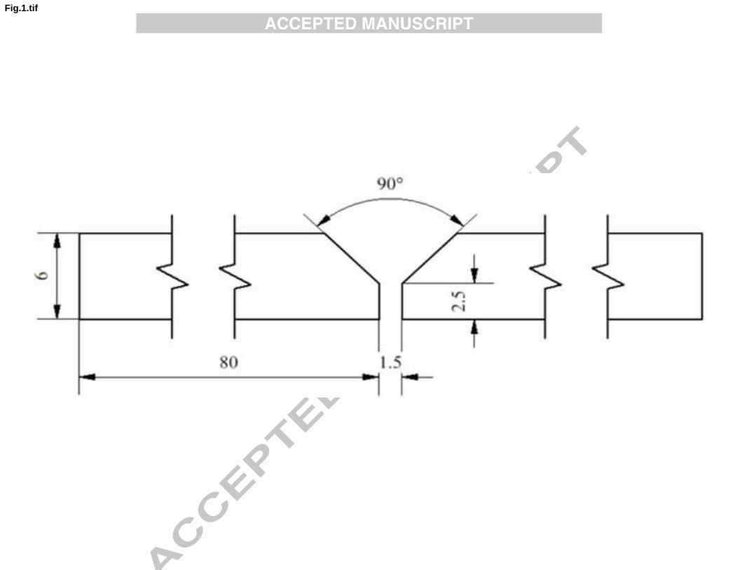
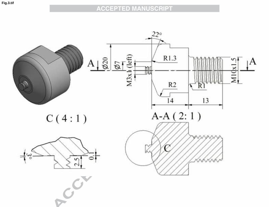
Different non-consumable tools were used for each specimen type. Figures 3 and 4 show the geometries
of the tools used for post-processing MIG welded plates, with and without reinforcement, respectively.
The nomenclature MIG_R+FSP applies to the MIG welds with Reinforcement and post-processed by
FSP, while the nomenclature MIG_NR+FSP applies to the MIG welds without reinforcement (Non-
Reinforced) and post-processed by FSP.
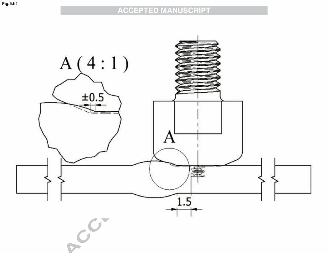
In the case of MIG_R+FSP plates, the tool was aligned with the weld, with the pin moved away from the
weld toe so that the truncated cone with an angle equal to 22° keeps interfering with adjacent weld in
about 0.5 mm (Figure 5). Due to the finite stiffness of the Cincinnati milling machine, the apparent depth
of pin penetration was set to 2.9 mm in order to obtain an actual depth of 2.5 mm. This apparent depth of
pin penetration was empirically determined in order to achieve an adequate pressure on the shoulder,
which is essential to avoid the formation of defects on the processed material. Post-processing was
performed in all four weld toes, one pass for each weld toe, matching the advancing side of the tool to the
weld toe.
Both the pin and the shoulder of the tool used in MIG_R+FSP have a smaller diameter than that used in
MIG_NR+FSP, allowing greater proximity to the weld toe and thereby producing a thicker refined layer
in this zone.
MIG_NR+FSP specimens were FS processed by performing four passes with the tool geometry presented
in Figure 4 and using an apparent depth of pin penetration of 3.4 mm which corresponds to an actual
depth of 3 mm . In order to avoid many passes for processing the entire MIG fusion zone, the overlap
ratio (OR), as defined by equation 1 [13], was set to 0 with a pin of 4 mm diameter, larger than the tool
diameter used for the MIG-R+FSP series.
pdlOR −=1 (1)
Where dp is the pin diameter and l is the distance between the pin axis in two successive passes.
In this case, the centre line of the MIG weld zone overlaps with both retreating sides of the two nearest
passes, resulting in a mirrored arrangement. The retreating side of the outer passes overlaps with the
advancing side of the passes closer to the centre line. The same procedure and parameters were used for
post-processing both MIG_R+FSP and MIG_NR+FSP series, and were chosen based on previous FSW
experiments [7, 10]. The FSP parameters were: tool rotation speed of 1500 rpm, travelling speed of 240
mm/min, and a tilt angle of 2.5º. Processing was carried out in order to produce welds with good surface
appearance, microstructure refinement, as well as to remove typical MIG defects (such as porosity and
lack of wetting) at the weld toe, but without creating FS defects, such as tunnel defects.
5
2.4. Metallography, hardness and residual stress testing
Cross-sectioning of the welds in planes perpendicular to the welding direction was performed for
metallographic analysis in order to identify the different weld zones, as well as the presence of MIG
welding defects, such as porosity and lack of wetting, and FSP defects such as tunnels. The samples were
prepared according to standard metallographic practice ASTM E3-11, and etched with modified Poulton´s
reagent. Detailed images of MIG weld microstructures were obtained in the base material, the heat
affected zone, the melted zone, the fusion line and the weld toe, while in FS post-processed welds the
images were captured at the weld toe, in the thermo-mechanically-affected and heat-affected zones, on
advancing and retreating sides, and in the nugget zone.
Vickers hardness testing was performed according to ASTM E384–11e1 using a Struers Duramin 1
microhardness tester with a 0.2 kg load and 0.5 mm between indentations, measured along a line 0.5 mm
from the plate surface.
Surface residual stress determination was performed by X-ray diffraction using the sin2ψ method with
PROTOiXRD equipment, working on Ω mounting. Measurements were performed at the toe of both the
MIG reinforced weld and the post-processed MIG reinforced weld on irradiated areas of 1.2x5 mm2. The
value of 5 mm for the irradiated area was in the weld longitudinal direction, whereas the value of 1.2 mm
was set in the weld transverse direction.
2.5. Tensile and fatigue testing
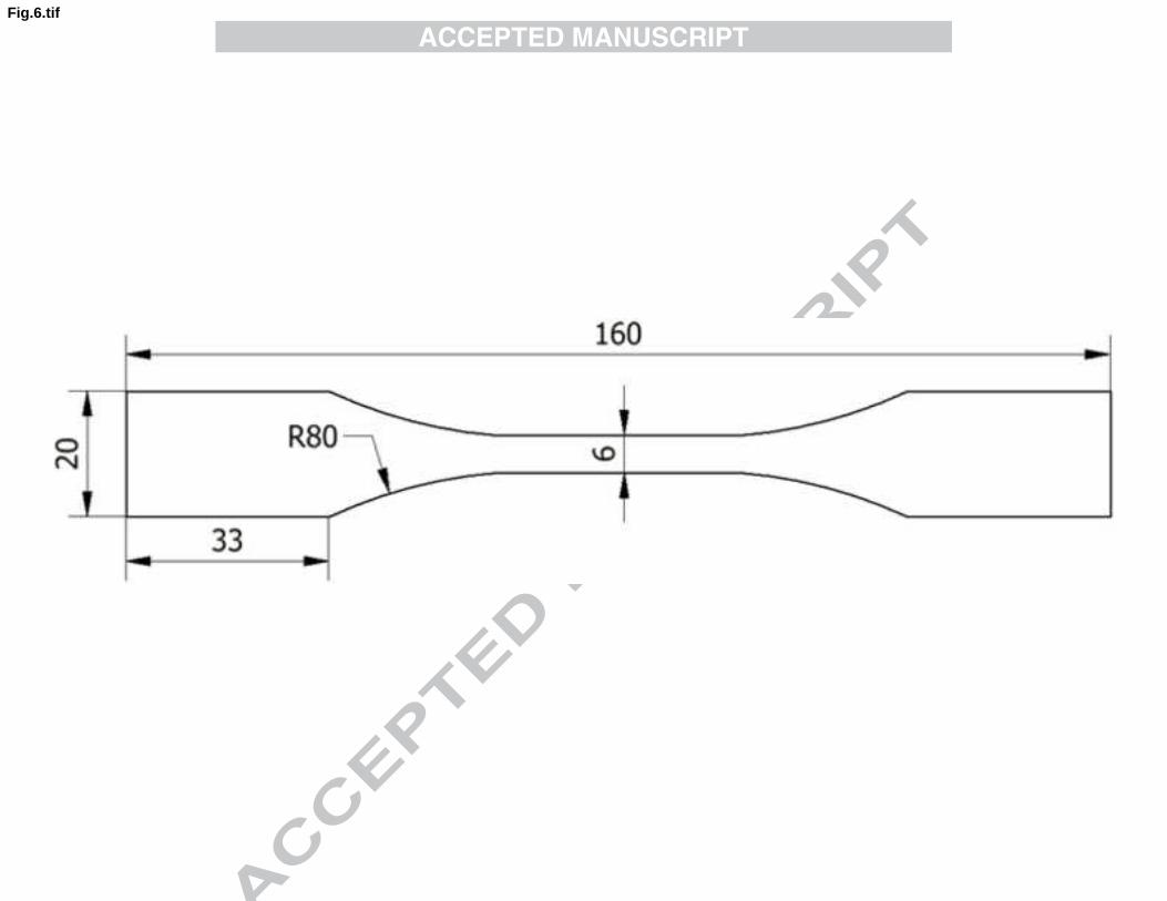
After welding and post-processing, small slices of 20x160 mm were removed from the welded plates
transversely to the welding direction for tensile and fatigue testing. Tensile specimens were also removed
from parent plates and machined according to the geometry shown in Fig. 6.
Tensile tests were carried out at room temperature in an Instron mechanical tensile/compression testing
machine, model 4206, using a testing speed of 2 mm/min. Fatigue tests were carried out in an Instron
hydraulic machine, applying a sinusoidal load wave to the specimens perpendicular to the weld seam (i.e.
in the material rolling direction), using a frequency of 20-30 Hz, depending upon the stress level, a stress
ratio set to R=0, and stress ranges between 75 and 180 MPa. The load amplitude and mean load, required
as input data for fatigue tests, were calculated taking into account the values of stress range Δσ, thickness
B in the welding zone, the width W of the specimen, and stress ratio R. Fatigue results were plotted as S-N
curves, presenting the stress range against the number of cycles to fracture. Life was defined as the
number of cycles to failure, and a total of 50 specimens were tested.
6
3. Results and discussion
3.1. Morphological analysis
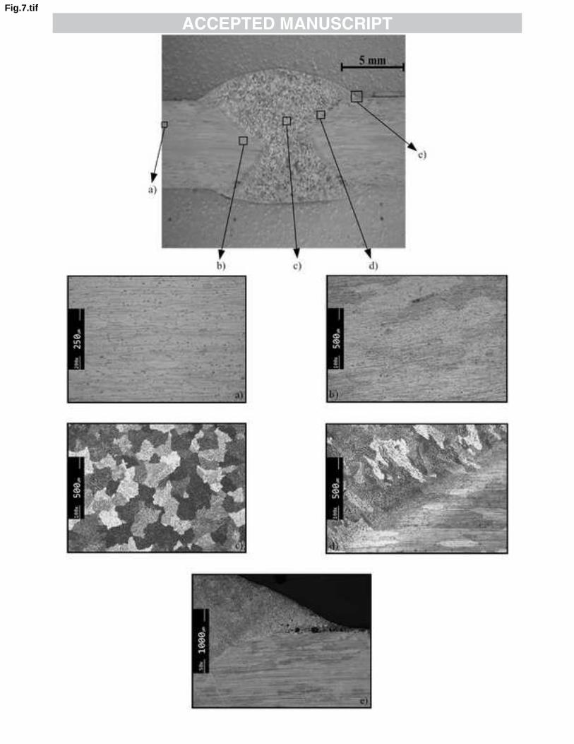
Fig. 7 illustrates the microstructures observed in a MIG weld before any post-processing. The base
material consists of grains elongated in the rolling direction, as shown in Fig. 7 a). This microstructure
was partially destroyed in the zone affected by the heat, as is illustrated in Fig. 7 b) and d).
The melted zone is formed by approximately equiaxed grains of 100-120 µm in the centre of the layers,
see Fig. 7 c), and grains elongated following the direction of the heat flow close the fusion line, see Fig. 7
d), except in the region affected by the second weld pass, where grain refinement was observed. Defects
such as porosity and lack of wetting are present in the weld toe, as illustrated in Fig. 7 e).
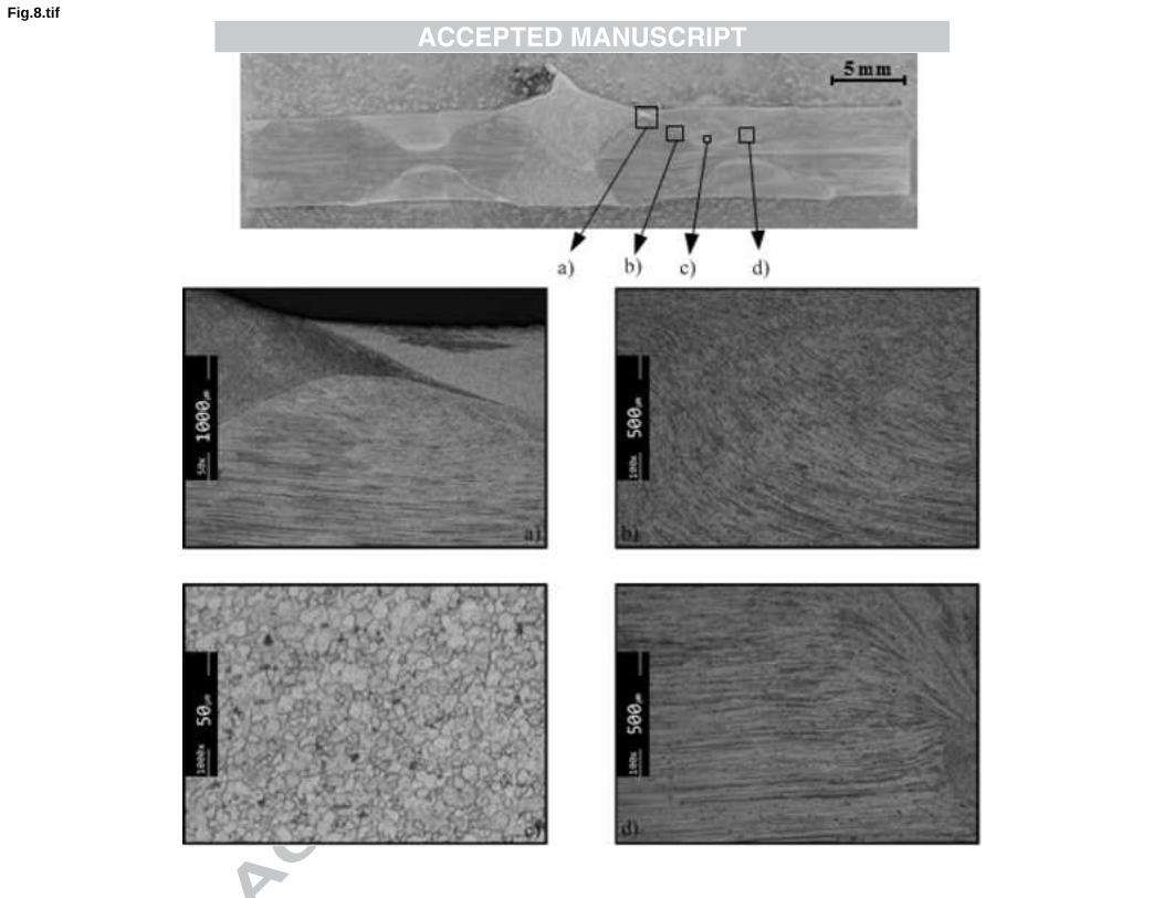
The effect of FS post-processing of MIG welds with reinforcement is clearly shown in Figure 8, where
four post-processing passes are visible. Fig. 8 a) shows the interaction between an FS processing pass and
the weld metal deposited by the MIG process in a higher magnification. Figures 8 b) and d) illustrate the
transition between the thermo-mechanically-affected zone and the heat-affected zone, in the advancing
and retreating sides respectively, where the grain was plastically deformed but not recrystallized, and the
direction of the material flow is clearly visible. The Fig. 8 c) shows the nugget zone where the refined
grains, with an average diameter 3.5 -6.5 µm, are not visible at that magnification, whereas the material
flow lines are clearly visible. When compared with the base material, with a pancake grain length of 135-
150µm, a large grain refinement was produced by the FSP.
Another important effect of FSP, besides grain refinement, is the removal of defects like porosity and lack
of wetting in the toe region, as shown by comparing Fig. 7 e), the toe of weld (TW), and Fig. 8 a), the toe
of post-processed weld (TPW).
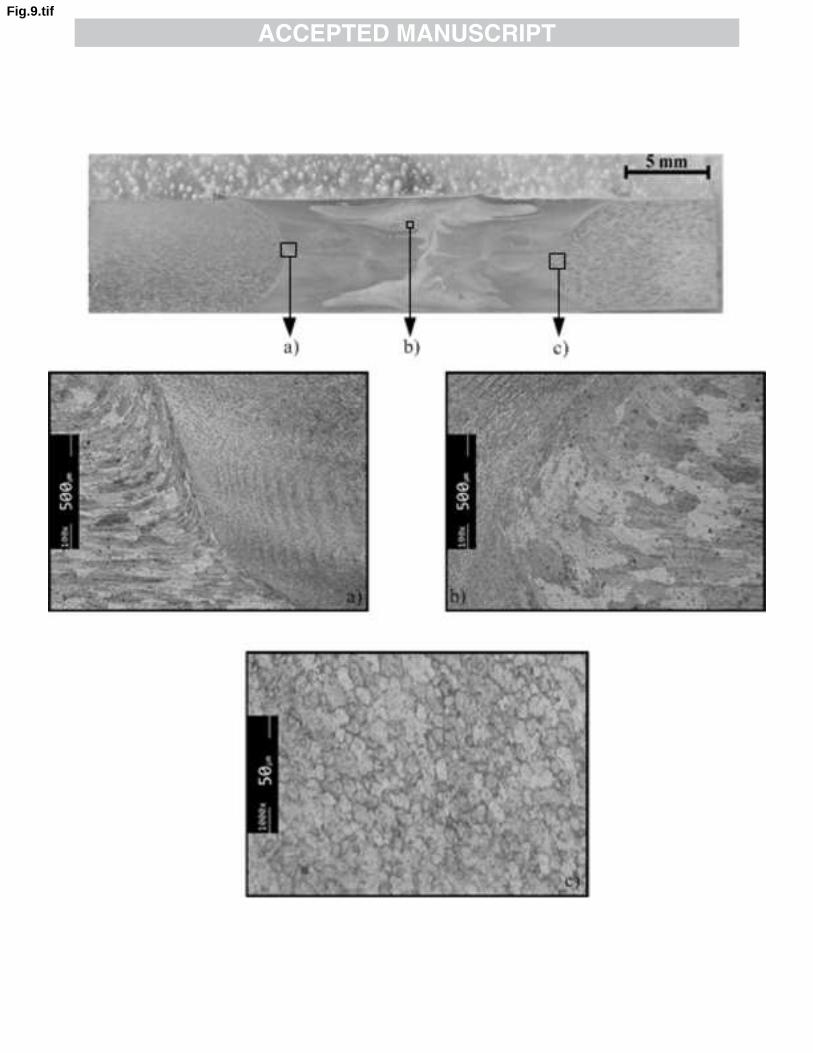
The metallographic analysis of the cross section of a post processed MIG_NR weld is shown in Fig. 9,
where the four passes for each side can be seen. Figs. 9 a) and c) illustrate the thermo-mechanically-
affected zone/heat-affected zone transition in the advancing side. Fig. 9 b) shows the refined melted
material after being processed in the nugget, close to the retreating side, where complex material flow
paths can be observed. MIG welds in that zone displayed an average grain size of approximately 100 m,
while the grain size after processing was only 5-8 µm.
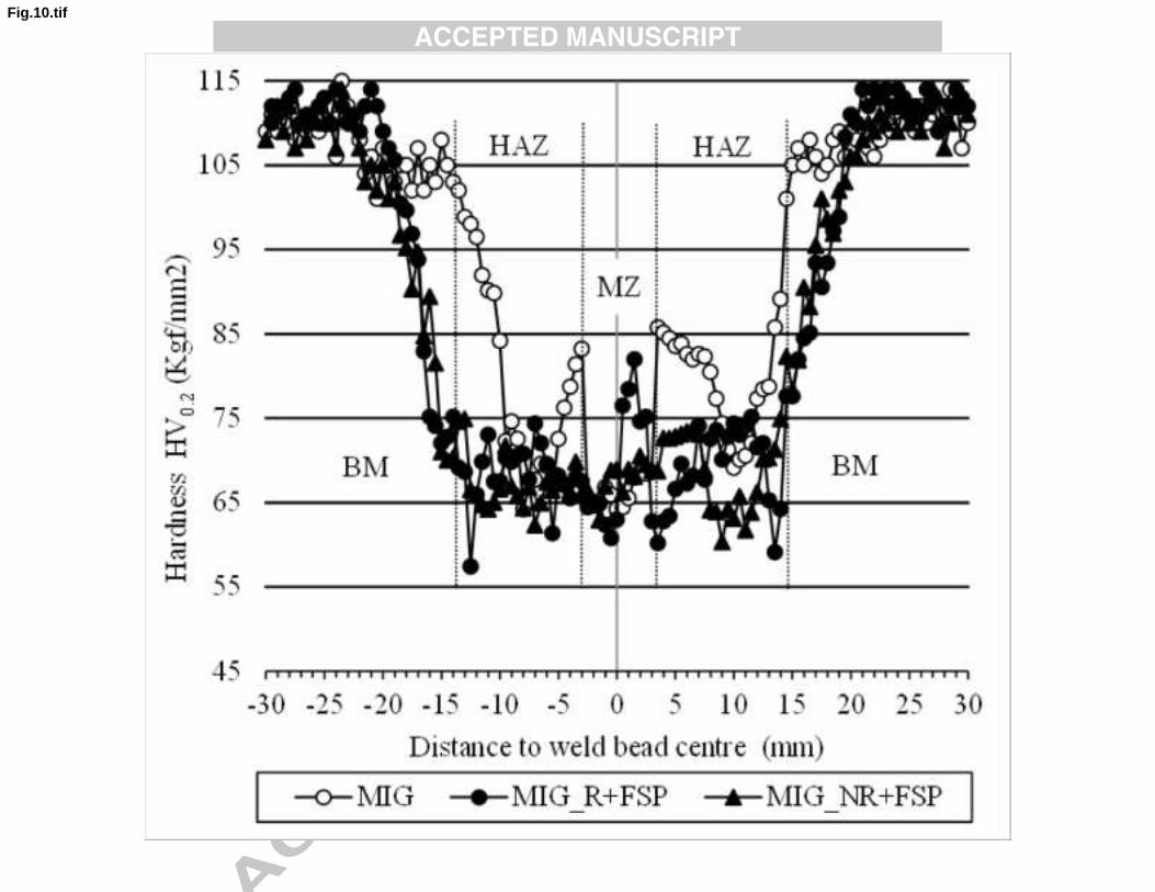
3.2. Hardness
Hardness profiles of the welds before and after processing, measured in the cross section, are shown in
Fig. 10. This image shows that all the welds, unprocessed and processed, display a significant decrease in
hardness in the TMAZ and HAZ. This decrease is due to the dissolution of strengthening precipitates in
7
the thermo-mechanically- affected zone and also coarsening of precipitates in the heat -affected zone as
mentioned elsewhere [14,15]. The hardness peaks observed in the melted region of MIG welds are due to
some reprecipitation which occurs during weld cooling.
The completion of post-processing does not alter the hardness of MIG welds significantly, because the
main mechanism of hardening for this aluminium alloy is not grain refinement or plastic deformation, but
the presence of hardening precipitates, already dissolved by MIG welding. However, the aforementioned
hardness peaks were removed due to the dilution of reprecipitation during friction stir processing. The
regions with loss of hardness are wider in FS post-processed welds than in MIG welds because post-
processing was performed in the MIG weld leg of either side, as shown in Fig. 10, producing dissolution
and coarsening of precipitates in a wider band.
3.3. Tensile strength-testing
The results of tensile tests of unprocessed and processed welds are shown in Table 4. In both a
significant reduction in tensile strength, consistent with the reduction of hardness shown in Fig. 10, was
observed.
The values in the table 4 represent the average of at least three specimens. The weld efficiency of
unprocessed and processed specimens is also shown. Weld efficiency is defined as the relationship
between the tensile strengths of the welds and the base material. All the specimens presented a weld
efficiency lower than the unit, which means they were in the undermatch condition. This reduction in
mechanical strength in fusion welds or friction stir welds in heat-treatable aluminium alloys is common
and has been reported in the literature [14-16].
Table 4 also shows that all welded specimens suffered a drastic reduction of elongation at maximum load.
This is due to the local reduction of mechanical strength, which leads to the concentration of plastic
deformation in the weakest zones, (TMAZ and HAZ), leading to an overall reduction in the elongation of
the welded specimens when compared with those taken from the base metal.
Post processing has little favourable effect on elongation, as illustrated in Table 4, mainly due to the
increased width of the weakest zone, as shown by the hardness fields illustrated in Figure 10. MIG
welded specimens failed in the HAZ, while the post-processed specimens failed in the retreating side
(MIG_R) and advancing side (MIG_NR) of the FSP, precisely in the zones where the lowest hardness
values coincide with the MIG HAZ (see Figure 10).
3.4. Fatigue strength
Fig. 11 presents the fatigue results for the four welded specimen series and base material, plotting the
nominal stress range against the number of cycles to failure. The MIG_NR series is plotted above the
8
MIG_R series. Therefore, an increase in the fatigue strength was obtained for the MIG_NR series
compared with the MIG_R series, due to the removal of reinforcement in the MIG_NR specimens.
The S-N curve of the MIG_NR+FSP series is clearly above the S-N curve of the MIG_NR series. With
regards to the MIG_R+FSP series it also presents superior behaviour when compared with that of the
MIG_R series. Therefore, both cases show the favourable effect of FS post-processing on fatigue
strength. However, even the MIG_NR+FSP series is clearly below the base material S-N curve. This
relative decrease in fatigue strength of 30% for a fatigue life of 105 cycles can be explained by the
decrease in mechanical strength of the welded series. Figure 10 shows that the welded specimen series
hardness decreased to 65 HV0.2 when compared with the base material (115 HV0.2). This loss of hardness
was caused by the microstructural changes produced by both MIG and FS processes (see above).
The increase in fatigue strength produced by FS processing can be explained by the following: i) change
of geometry, especially due to the increase of curvature radius; ii) microstructure modification or porosity
elimination; iii) an possible decrease of residual stress. In order to evaluate the influence of the geometry
on the fatigue strength, the Lawrence equation (eq. 2) for butt welds [18] and the Peterson equation (eq.
3) [19] were used to calculate kt and kf factors, respectively:
2/14/1)(tan27,01 ⎟⎟⎠
⎞⎜⎜⎝
⎛⋅⋅+=
ρθ tkt (2)
ρa
kk tf
+
−+=1
11 (3)
where is the weld angle and is the weld toe radius of curvature, t the thickness and kt and kf the
theoretical and fatigue stress concentration factors of the reinforced specimens, respectively. The material
constant a is 0.51 mm for aluminium alloys [19].
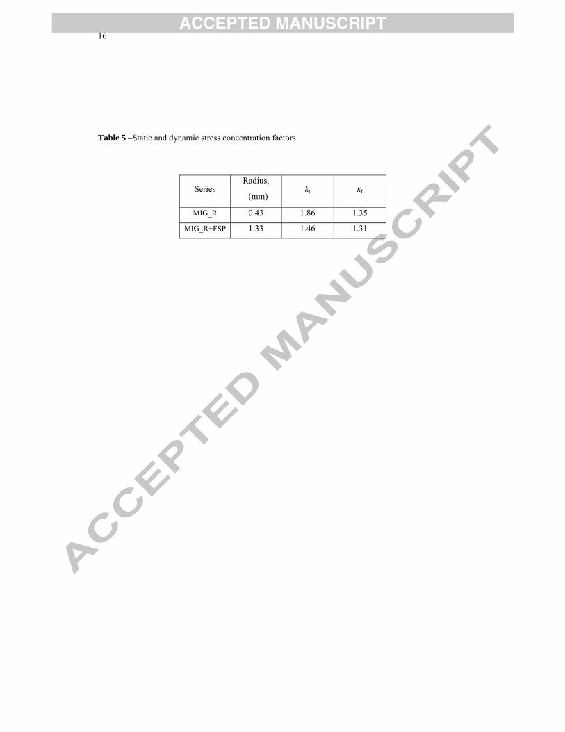
In order to calculate these parameters, the geometry of the welds of the MIG_R and MIG_R+FSP series
was analysed statistically, using a Gauss distribution. An average angle of 22.7º and an average curvature
radius of 0.43 mm were obtained, both measured in the MIG_NR welds toe. For the post-processed
MIG_R+FSP series, an average curvature radius of 1.33 mm was obtained. Table 5 summarizes the
values obtained for kt and kf factors for MIG_R and MIG_R+FSP series.
The local stress range at the weld toe Δσloc was calculated from the nominal stress range Δσnom using
equation 4:
fnomloc k⋅Δ=Δ σσ (4)
9
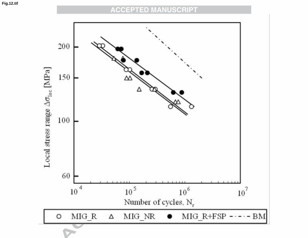
Figure 12 presents the fatigue results for the MIG_R, MIG_NR and MIG_R+FSP series plotting the local
stress range against the number of cycles to failure. It should be pointed out that the geometric factor is
absent from these curves as they are plotted in terms of local stresses. The MIG_R and MIG_NR series
are nearly superimposed, which indicates that the use of equation 4 with the values of kf calculated by
empirical equation of Peterson [19] is adequate.
The MIG_R+FSP series curve is clearly above those of MIG_NR and MIG_R . Therefore, it can be
concluded that the increase of about 25% observed in fatigue strength was largely due to the improvement
of microstructure, the reduction or removal of MIG welding defects, and a possible decrease in the
residual stress field.
3.5. Residual stresses
The fatigue behaviour of MIG welds and FS post-processed welds is largely affected by residual stresses
in the transversal direction because they are applied in the same direction as fatigue loading. However,
the residual stresses measured at the toes of both MIG reinforced welds (MIG_R) and MIG reinforced
welds submitted to FS processing (MIG_R + FSP) were approximately zero (σt = 0), which means they
have no influence on the improvement in fatigue behaviour obtained in this study. The weld toe was the
zone of interest for the residual stress measurements since fatigue cracks tend to initiate from this area.
The choice of an irradiated area of 5x1.2 mm took the following factors into consideration. It is widely
acknowledged that residual stress fields present no significant variation in the longitudinal direction of the
weld. Therefore, by choosing a high value of 5 mm for the irradiated area in the longitudinal direction, the
resolution of residual stress measurement in the weld toe was increased. Moreover, the value of 1.2 mm
used for the irradiated area in the transverse direction was the lowest value that enables reliable
measurement of residual stresses, close the weld toe, where a typically large stress gradient exists in the
transverse direction of the weld. It should be emphasized that residual stress measurement by X-ray
diffraction in welds of aluminium alloys is a difficult task, particularly when performed at the weld toe.
James et al [20, 21] found similar residual stress results for MIG and FSW welds on both 5083-H321 and
5383-H321 aluminium alloys 8 mm thick, using synchrotron diffraction strain scanning of the toe at a
depth of 1 mm.
10
4. Conclusions
This study analysed the use of friction stir processing to improve fatigue behaviour in AA6082-T6
aluminium alloy MIG butt welds. Four weld series were analysed: MIG welds (with and without
reinforcement) and FS post-processed welds (with and without reinforcement). The following conclusions
were drawn:
Friction stir processing does not alter the hardness and mechanical strength of MIG welds significantly,
but improves their ductility slightly.
Friction stir processing does not greatly affect transverse residual stress in the toe of MIG welds.
Non-reinforced MIG welds showed substantially longer fatigue lives than reinforced welds.
Friction stir processing improves fatigue life of reinforced and non-reinforced MIG welds significantly.
This improvement was caused by geometric modification, grain refinement and the removal of previous
defects, such as porosity and lack of wetting, in the weld toe.
11
Acknowledgements
The authors gratefully acknowledge the Portuguese Foundation for Science and Technology for funding
the work reported, Project nº PTDC/EME-PME/114605/2009 co-financed by FEDER, through the
Operational Factors for Competitiveness Programme of the QREN with reference COMPETE: FCOMP-
01-0124-FEDER- 015165.
This research is sponsored by FEDER funds through the program COMPETE – Programa Operacional
Factores de Competitividade – and by national funds through FCT – Fundação para a Ciência e a
Tecnologia –, under the project PEst-C/EME/UI0285/2011.
The authors also thank Thyssen Portugal - Steels and Services Ltd., Marinha Grande, for providing heat
treatments of friction stir processing tools, and Centro de Estudos de Materiais por Difração de Raios-X
(CEMDRX), Coimbra, for the measurement of the residual stresses in welds.
12
References
[1] Holliday DB, Westinghouse Electric Corporation. Gas-Metal Arc Welding, In: ASM International Handbook Committee, editors, Welding, Brazing, and Soldering, United States of America: ASM International; 2004, p. 569-581.
[2] ESAB MIG Welding Handbook; 2005,p.111-124.
[3] Thomas WM, Nicholas ED, Needham JC, Murch MG and Dawes CJ. G.B. Patent Application No.9125978.8, Dec. 1991.
[4] Mishra RS, Ma ZY. Friction stir welding and processing. Mater. Sci. Eng2005; R50:1–78.
[5] Weifeng Xu, Jinhe Liu, Hongqiang Zhu, Li Fu, Influence of welding parameters and tool pin profile on microstructure and mechanical properties along the thickness in a friction stir welded aluminum alloy, Materials and Design 47 (2013) 599–606.
[6] Basil Darras, Emad Kishta, Submerged friction stir processing of AZ31 Magnesium alloy, Materials and Design 47 (2013) 133–137.
[7] Costa JD, Ferreira JAM, Borrego LP, Abreu LP. Fatigue behaviour of AA6082 friction stir welds under variable loadings. IntJStrucInte2011;2:122-134.
[8] Moreira PMGP, de Figueiredo MAV, de Castro PMST. Fatigue behaviour of FSW and MIG weldments for two aluminium alloys. Theor Appl Fract Mec2007;48:169–177.
[9] Ericsson M, Sandström R. Influence of welding speed on the fatigue of friction stir welds, and comparison with MIG and TIG. Int J Fatigue 2003;25:1379–1387
[10] Costa JD, Ferreira JAM, Borrego LP, Abreu LP. Fatigue behaviour of AA6082 friction stir welds under variable loadings. Int J Fatigue, 2012;37:8-16.
[11]Elwin LR, Aluminum Company of America. Introduction to Aluminum and Aluminum Alloys, In: ASM International Handbook Committee, editors. Properties and Selection: Nonferrous Alloys and Special-Purpose Materials, United States of America: ASM International; 2004, p. 16-39.
[12] ASTM - American Society for Testing and Materials. Standard Test Methods for Determining Average Grain Size 2003; Designation: E 112 – 96e2.
[13] Nascimento N, Santos T, Vilaça P, Miranda RM, Quintino L. Microstructural modification and ductility enhancement of surfaces modified by FSP in aluminium alloys. Mater Sci Eng A2009;506:16-22.
[14] Leal RM, Loureiro A. Microstructure and mechanical properties of friction stir welds in aluminium alloys 2024-T3, 5083-O and 6063-T6. Mater Sci Forum2006;514-516:697-701.
[15]Svensson LE, Karlsson L, Larsson H, Karlsson B, Fazzini M, Karlsson J. Microstructure and mechanical properties of friction stir welded aluminium alloys with special reference to AA 5083 and AA6082. Sci Technol Weld Joining 2000;5:285-297.
[16] Jata KV, Sankaran KK, Ruschau JJ. Friction-stir welding effects on microstructure and fatigue of aluminum alloy 7050-T7451. Metall Mater Trans A2000;31:2181-2192
[17] Mroczka K, Pietras A. FSW characterization of 6082 aluminium alloys sheets. Archives of Mater Sci Eng A 2009;40:104-109.
[18] Yung JY, Lawrence FV. Analytical and Graphical aids for the fatigue design of weldments. Fatigue Fract Eng Mater Struct1985;8-3:223-241.
[19] Peterson, RE. Analytical Approach to Stress Concentration Effect in Aircraft Materials, U.S. Air Force-WADC Symposium on Fatigue of Metals, Technical Report 59-507, Dayton, Ohio, 1959,p. 273.

13
[20] James MN, Hughes DJ, Hattingh DG, Mills G, Webster PJ. Residual stress and strain in MIG butt welds in 5083-H321 aluminium: As-welded and fatigue cycled. Inter J Fatigue 2009;31:28-40
[21] James MN, Hughes DJ, Hattingh DG, Bradley GR, Mills G, Webster PJ. Synchrotron diffraction measurement of residual stresses in friction stir welded 5381-H321. Fatigue Fract Eng Mater Struct 2004;27:187-202
14
Figure captions
Fig.1 –Joint preparation (dimensions in mm).
Fig.2 – Friction stir post-processing of a MIG_R plate.
Fig. 3 –Geometry of the tool used for post-processing MIG_R+FSP specimens (dimensions in mm).
Fig. 4 –Geometry of the tool used for post-processing MIG_NR+FSP specimens (dimensions in mm).
Fig. 5 – Schematic representation of plate/tool position (dimensions in mm).
Fig. 6 – Geometry of base material tensile specimens 6 mm thick (dimensions in mm).
Fig. 7 –Metallographic analysis of MIG welds, a) base material, (BM) b) heat affected zone, (HAZ) c) melted zone, (FZ) d) fusion line (FL) and e) toe of weld (TW).
Fig. 8 – Metallographic analysis of the cross section of a post processed MIG_R weld: a) toe of a post-processed weld (TPW); b) thermo-mechanically-affected zone/heat-affected zone advancing side (TMAZA). c) Nugget (NT) d) thermo-mechanically-affected zone/heat-affected zone retreating side (TMAZR).
Fig. 9 – Metallographic analysis of the cross section of a post processed MIG_NR weld: a) thermo-mechanically affected zone/nugget zone at advancing side (TMAZA); b) refined melted material at retreating side; c) nugget/thermo-mechanically affected zone/ at the advancing side (TMAZA).
Fig. 10 – Hardness profiles of unprocessed and processed welds: BM – Base material; HAZ – Heat affected zone; MZ – Melted zone.
Fig. 11 –Results of fatigue tests: nominal stress range versus number of cycles to failure.
Fig. 12 –Results of fatigue tests: local stress range versus number of cycles to failure.
15
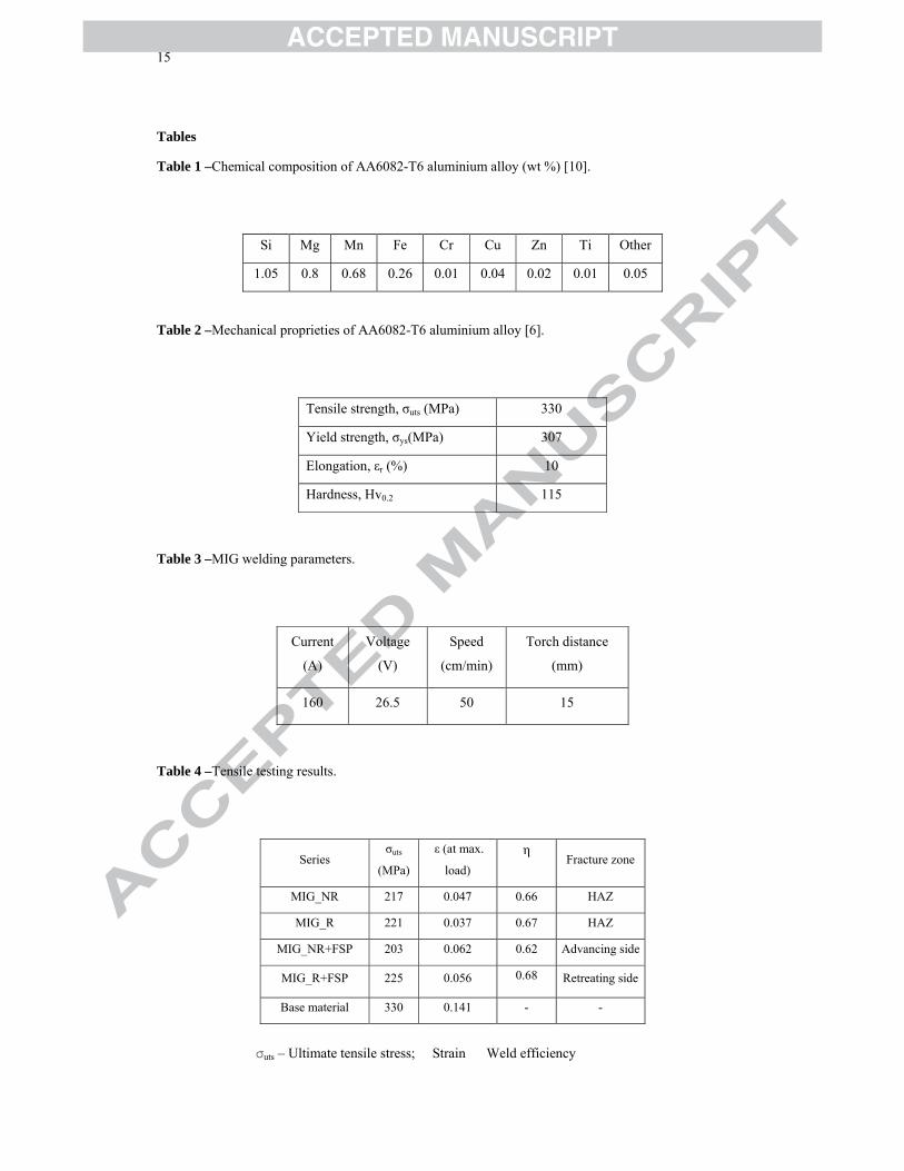
Tables
Table 1 –Chemical composition of AA6082-T6 aluminium alloy (wt %) [10].
Si Mg Mn Fe Cr Cu Zn Ti Other
1.05 0.8 0.68 0.26 0.01 0.04 0.02 0.01 0.05
Table 2 –Mechanical proprieties of AA6082-T6 aluminium alloy [6].
Tensile strength, σuts (MPa) 330
Yield strength, σys(MPa) 307
Elongation, εr (%) 10
Hardness, Hv0.2 115
Table 3 –MIG welding parameters.
Current
(A)
Voltage
(V)
Speed
(cm/min)
Torch distance
(mm)
160 26.5 50 15
Table 4 –Tensile testing results.
σuts – Ultimate tensile stress; Strain Weld efficiency
Series σuts
(MPa)
ε (at max.
load) η
Fracture zone
MIG_NR 217 0.047 0.66 HAZ
MIG_R 221 0.037 0.67 HAZ
MIG_NR+FSP 203 0.062 0.62 Advancing side
MIG_R+FSP 225 0.056 0.68 Retreating side
Base material 330 0.141 - -
16
Table 5 –Static and dynamic stress concentration factors.
Series Radius,
(mm) kt kf
MIG_R 0.43 1.86 1.35
MIG_R+FSP 1.33 1.46 1.31
17
HIGHLIGHTS
Friction stir processing does not alter hardness and mechanical strength of MIG welds.
Friction stir processing improves fatigue life of reinforced and non-reinforced MIG welds.
Friction stir processing removes previous defects, such as porosity and lack of wetting.