Embed Size (px)
Citation preview

Fast sampling for Picosecond timing
Jean-François Genat
EFI Chicago, Dec 17-18th 2007

Outline
• Time picking strategies
• Timing using MCPs
• Fast Sampling chip
• Technologies
• Conclusions
Jean-Francois Genat, EFI, Dec 17-18th 2007, Chicago

Time picking techniques
Jean-Francois Genat, EFI, Dec 17-18th 2007, Chicago
Discriminators can be:
- Single Threshold- Derivative’s Zero-crossing- Multiple Thresholds- CFDs (many flavours)
All make assumptions on the signal waveformdepending upon detector + front end processing
Fast sampling and digitization
Extract most of the pulse information if sampling is fast enough to resolve the signal rise-time
Digital processing allows any kind of time (and amplitude) extractionTime accuracy depends on the sampling rate and amplitude ranges

10-100 GHz sampling
Fast sampling:
High rate sampling and pulse reconstruction knowing the waveform allows to get accurately:
- Amplitude- Time
using for instance least squares algorithms (Cleland & Stern)
On-chip digital oscilloscopes, integrated in multi-channel analog memory chips: Labrador (Hawaii), SAM (Saclay)Digital signal processing can also be integrated
Jean-Francois Genat, EFI, Dec 17-18th 2007, Chicago

Outline
• Time picking strategies
• Timing using MCPs
• Fast Sampling chip
• Technologies
• Conclusions
Jean-Francois Genat, EFI, Dec 17-18th 2007, Chicago

MCPs timing performance
Jean-Francois Genat, EFI, Dec 17-18th 2007, Chicago

Fast signals
-0,45
-0,4
-0,35
-0,3
-0,25
-0,2
-0,15
-0,1
-0,05
0
0,05
0,1
1
50
9
10
17
15
25
20
33
25
41
30
49
35
57
40
65
45
73
50
81
55
89
60
97
66
05
71
13
76
21
0 1 2 3 4 5 ns
Jean-Francois Genat, EFI, Dec 17-18th 2007, Chicago

Fast Sampling with Si detectorsInput signal 30ns peaking time(detector + noise)S/N = 30
Noise spectrumSerial, 1/f
Amplitude and time spreadssigma(a) =2%, sigma(t)= 1.2 ns
Peaking time = 50ns
Jean-Francois Genat, EFI, Dec 17-18th 2007, Chicago
A few nanoseconds measured (M. Friedl, M. Pernicka, Vienna)

Fast sampling simulations
Jean-Francois Genat, EFI, Dec 17-18th 2007, Chicago
Peaking time = 200ps256 samplesS/N=50
Sigma(time) = 6ps
Peaking time = 160ps128 samplesS/N=60
Sigma(time) = 8.3ps
Residual (no noise) : 3ps
Simulated waveforms: White noise added to randomly delayed pulses
2ns 1ns
No sensitivity to amplitude distributionInfinite dynamic range assumed

Outline
• Time picking strategies
• Timing using MCPs
• Fast Sampling chip
• Technologies
• Conclusions
Jean-Francois Genat, EFI, Dec 17-18th 2007, Chicago

10-100 GHz sampling
Output
Counter and picosecond Vernier timer
ReadCntrl
Triggeringdiscriminators
Analog storage
Inputs
Figure 1 Fast sampler block diagram
Write and Read control
WilkinsonAD
Timestamps
500 MHz Clock
Jean-Francois Genat, EFI, Dec 17-18th 2007, Chicago

Blocks
Jean-Francois Genat, EFI, Dec 17-18th 2007, Chicago
Capacitor bank (SCA):- number of channels- depth- dynamic range- droop, crosstalk
Timing generator - time step- clock frequency- use Vernier to increase sampling
frequency
Triggering Discriminators - threshold- speed - delay
ADC (Wilkinson) - number of channels- number of bits- clock speed
Control and processing
Overall:- input to SCA bandwidth - temperature sensitivity- calibration - power
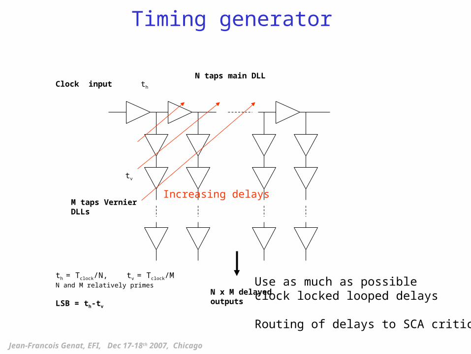
Timing generator
Jean-Francois Genat, EFI, Dec 17-18th 2007, Chicago
N taps main DLLClock input
th = Tclock/N, tv = Tclock/MN and M relatively primes LSB = th-tv
M taps Vernier DLLs
N x M delayed outputs
th
tv
Increasing delays
Use as much as possibleclock locked looped delays
Routing of delays to SCA critical

Digital Delay Lines: DLL
Clock feeds the digital delay line Phase arbiter locks delays on clock period
Delay locked loop:Interpolate delays within a clock period
N delay elements Delays control
Time arbiter
Clock
M. Bazes IBM, Proc. IEEE JSSC 1985 p 75
Jean-Francois Genat, EFI, Dec 17-18th 2007, Chicago
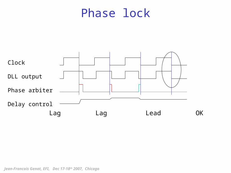
Phase lock
Lag Lag Lead OK
Clock
DLL output
Phase arbiter
Delay control
Jean-Francois Genat, EFI, Dec 17-18th 2007, Chicago

Delay elements
Active RC element: R resistance of a switched on transistor C total capacitance at the connecting node
Typically RC = 1-100 using current IC technologies
N delay elements
NN is technology dependent: the fastest, the best !
Within a chip ~ 1 % a wafer ~ 5-10% a lot ~ 10-20%
[Mantyniemi et al. IEEE JSSC 28-8 pp 887-894]
Jean-Francois Genat, EFI, Dec 17-18th 2007, Chicago

Time controlled delay
CMOS Technology 90nm: ~ 20-40 ps 65nm in production today
Propagation delay ~ 10-100 ps
Delay controlsthru gatesvoltages
PMOS
NMOS
B=A
100ps TDC 0.6m CMOS (1992)
Spread=12 ps
Jean-Francois Genat, EFI, Dec 17-18th 2007, Chicago
PMOS
NMOS
Delay control thru Vdd
Vdd

Switched Capacitors Array
write read
reset
Jean-Francois Genat, EFI, Dec 17-18th 2007, Chicago
Flavours:
- Sampling Cap switched in the loop of an opamp - Differential implementation

Discriminators
Jean-Francois Genat, EFI, Dec 17-18th 2007, Chicago
Do not need the ps accuracy (reference is the main clock)Stops the sampling after a (programmable) delay

ADC
Jean-Francois Genat, EFI, Dec 17-18th 2007, Chicago
Wilkinson preferred in terms of power and Silicon areasince heavily parallel
See Eric Delagnes slide:
Fast Wilkinson:
Clock interpolated using a DLL 100 ps counter 10 times faster Same 12 bit accuracy

ILC 130nm Silicon strips chip
Waveforms
CMOS 130nm
Counter
Single ramp10 bits ADC
Can be used for fast decision
Ch #
Analog samplers
iVi > th (includes auto-zero)SparsifierChannel n+1
Channel n-1
Time tag
Preamp +Shapers
Strip
reset
Clock 3-96 MHz
reset
Jean-Francois Genat, EFI, Dec 17-18th 2007, Chicago
ADC

Outline
• Time picking strategies
• Timing using MCPs
• Fast Sampling chip
• Technologies
• Conclusions
Jean-Francois Genat, EFI, Dec 17-18th 2007, Chicago

Technologies
Jean-Francois Genat, EFI, Dec 17-18th 2007, Chicago
SiGe - Not many benefits compared to Deep Sub-Micron CMOS - In addition CMOS from BiCMOS not as fast as pure DSM CMOS
2006

CMOS
Jean-Francois Genat, EFI, Dec 17-18th 2007, Chicago
Present designs in CMOS:
CERN HPTDC IBM .25 m 25ps timing generator
development .13 m 6ps timing generator
Hawaii BLAB 1 TSMC .25 m 6 GHz 10b sampling dev 2 TSMC .25 m 10 GHz
Saclay SAM AMS .35 m 2 GHz 12b sampling
90nm CMOS available from MOSIS, Europractice
Drawbacks- Reduced voltage supply- Leaks

Outline
• Time picking strategies
• Timing using MCPs
• Fast Sampling chip
• Technologies
• Conclusions
Jean-Francois Genat, EFI, Dec 17-18th 2007, Chicago

Backup
J-F Genat, RP220/420 Paris Workshop, Sept 12th 2007
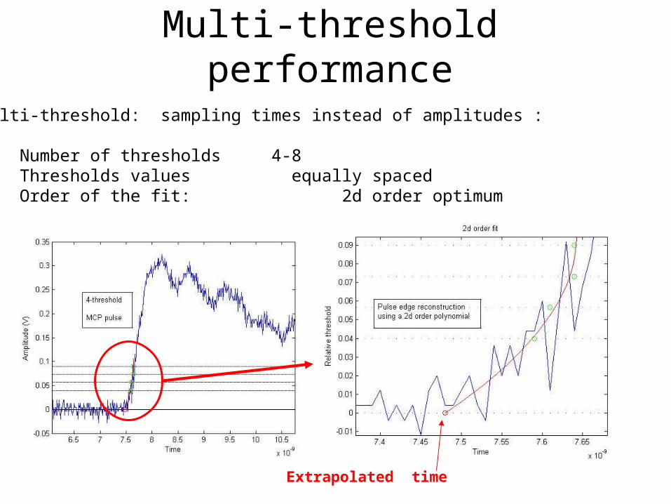
Multi-threshold performance
Multi-threshold: sampling times instead of amplitudes :
- Number of thresholds 4-8- Thresholds values equally spaced- Order of the fit: 2d order optimum
Extrapolated time

MCP PMT single photon signals
Actual MCPs signalsK. InamiUniv. NagoyaTr = 500pstts= 30ps
N photo-electrons improves as N
MCPs segmented anode signals simulation20 photoelectrons tts = 860 fsH. Frisch, Univ. Chicago + Argonne
Jean-Francois Genat, EFI, Dec 17-18th 2007, Chicago
BUT


![The Story of Picosecond Ultrasonicsperso.univ-lemans.fr/~pruello/Picosecond ultrasonics from lab to... · The Story of Picosecond Ultrasonics 1 Christopher Morath, ... [ps] 0.00 0.05](https://img.dokumen.tips/doc/110x75/5a8820a97f8b9aa5408e58d4/the-story-of-picosecond-pruellopicosecond-ultrasonics-from-lab-tothe-story-of.jpg)