Embed Size (px)
Citation preview
2250
1 Graduate Student, Institute of Engineering Mechanics, University of Tsukuba, Japan, [email protected] Associate Professor, Institute of Engineering Mechanics, University of Tsukuba, Japan, [email protected]
FAILURE MODE CLASSIFICATION OF REINFORCED CONCRETE COLUMNSBY THE ANALYSIS OF THE STRAIN DISTRIBUTION IN THE MAIN
REINFORCEMENT
Primo Allan T ALCANTARA1 And Hiroshi IMAI2
SUMMARY
A new approach in the classification of the resulting failure mode, whether shear, bond splitting orflexure, for reinforced concrete columns is presented. Particular emphasis is placed on theanalysis of the strain distribution in the main reinforcement based on the truss and arch modeltheory. The proposed alternative method is compared with results from several series of columnexperiments. The proposed method is shown to provide a high precision in classifying failuremodes with consideration of the presence of inner rows of main bars and axial loading.
INTRODUCTION
Failure of a reinforced concrete member, such as columns, are classified into three major types: shear, bondsplitting and flexural modes. Although it is common practice to rely on the observed crack patterns and theyielding of the steel reinforcement to determine the resulting failure mode, problems arose for specimensexhibiting features of more than one type of failure mode. Hence, there is difficulty in the evaluation of theultimate strength of the columns, especially whether it be for shear or for bond splitting.
An alternative approach in the classification of failure modes for reinforced concrete columns [Alcantara 1999]is presented. Aside from failure mode classification by the use of crack patterns, bar strains and ultimatestrengths, an analysis of the strain distribution in the main reinforcement is considered. Using the proposedmethod gives a different perspective wherein focus is given from within the interior of the column showing theactual behavior of the main reinforcement under loading. Test results on reinforced concrete columns showingthe strain distribution in the main reinforcement were used and compared, both qualitatively and quantitatively,with the theoretical strain distribution using the truss and arch model.
TRUSS AND ARCH MODEL THEORY
Predicting resulting failure modes is very essential in the design of columns to assure safety and adequateresistance to earthquake forces. Although there are existing equation regarding the shear, bond splitting andflexural capacities of columns, results showed some inconsistencies with regard to the theoretical andexperimental values as well as the observed crack patterns and reinforcing bar strains. The truss and archmechanisms were used in the calculations involving the shear and bond splitting capacities of columns while theultimate strength concept was applied for the flexural capacities. Moreover, a comparison of the theoreticalstrain distribution to the experimental strain distribution in the main reinforcement based on each of the failuremodes was done. The truss and arch model was also used in the calculations of the theoretical strains for theshear and bond splitting types while the equilibrium and strain compatibility assumptions were used for theflexural type. Finally, failure mode classification was performed using the data gathered.
Column Capacity
Failure of a column depends on its overall strength. Since the column could fail in either shear, bond splitting orflexure, the lateral force capacities according to the various failure modes were determined. The shear capacity
22502
of columns was calculated by the strength equation given in the design code of the Architectural Institute ofJapan [AIJ 1994] which is as shown in Eq. (1).
Qsu = Qsut + Qsua = bjtpwσwycotφ + tanθ(1-β)bDνσB/2 (1)
The bond splitting capacity of columns is mainly dependent on the bond strength of the main reinforcement.Among the proposed equations given for the bond strength of bars are those given by Fujii-Morita [Fujii 1983]and Kaku [Kaku 1994]. In the derivation of the bond splitting capacity, the truss and arch model was also madeas the basis of the shear resisting mechanism. The calculated bond strength using the proposed equations wasused as the controlling parameter in the derivation of the bond splitting capacity. Accordingly, the bond splittingcapacity is given by Eq. (2).
Qbu = Qbut + Qbua = τbu(Σψh)jt + tanθ(1-β)bDνσB/2 (2)
The calculation of the flexural capacity was based on the ultimate strength concept wherein the shape of theconcrete compression zone is represented by the stress-strain curve based on the e-function model [Muto 1964]and the stress-strain relationship for the main reinforcement is based on a bilinear elastic-perfectly plastic model.Considering the stress-strain conditions along the column cross section, an iterative procedure was done whereinat increasing values of the strain at the extreme compression fiber, locations of the neutral axis were determinedand the corresponding values of the lateral load can be calculated by moment equilibrium. The flexural capacity,Qmu, of the column corresponds to the maximum calculated value obtained from the above procedure.
Effect of Axial Loading
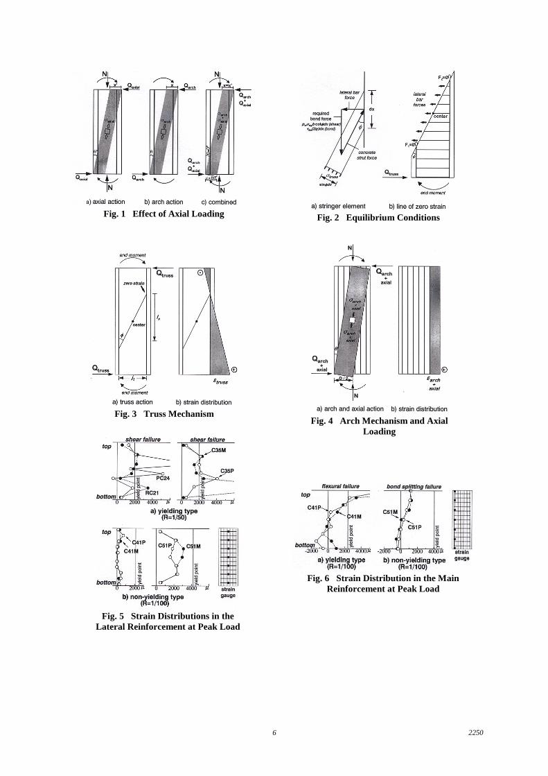
In the aforementioned discussion of the column capacity based on the truss and arch model, the loadingcondition on a regular beam, where axial loading is not applied, is considered. However, for columns, the levelof axial loading is relatively high and has a considerable effect on its overall behavior. Figure 1 (a) shows aschematic diagram of the behavior of the column having an axial load, N, when subjected to lateral seismicforces. It is shown that a concrete arch will be formed along the diagonal of the column [Nigel Priestley 1994]that would partly resist the axial load applied and the remaining of which would be carried by the mainreinforcement. Moreover, from equilibrium, it was derived that the lateral force due to the applied axial load,Qaxial, is resisted solely by the concrete arch and is given by Eq. (3).
Qaxial = σaxialbx’cosθ’sinθ’ (3)
Such analogy is very similar to the diagram representing the column behavior due to the arch mechanism asshown in Fig. 1 (b) except for the presence of axial loading. For this case, the lateral force, Qarch, is also resistedsolely by the concrete arch as shown in Eq. (4).
Qarch = σarchbxcosθsinθ (4)
In order to maximize the lateral force contribution due to the arch mechanism and the axial load, both diagramsare combined as shown in Fig. 1 (c) wherein the stress in the concrete arch is given by σarch+σaxial and theresulting lateral force is Qarch+Qaxial. From the figure, the depth and angle of the concrete arch for both the axialand arch actions are assumed to be identical. By a similar procedure as in the arch mechanism, the lateral forcedue to both actions is shown by Eq. (5).
Qarch+Qaxial = (σarch+σaxial)bDtanθ/2 (5)
However, the stress in the concrete arch can be equated to the remaining concrete capacity after considering thestress carried by the truss mechanism (σarch+σaxial = νσB-σtruss). Therefore,
Qarch+Qaxial = (νσB-σtruss)bDtanθ/2 (6)
Equation (6) shows that the total lateral force due to the arch mechanism and the axial load is equivalent to thelateral force contribution due to pure arch action given in Eqs. (1) and (2) for shear and bond splitting types,respectively. It is implied that even though the axial load provides an additional contribution to the lateral forcecapacity, it actually causes a corresponding decrease in the pure arch action contribution. Thus, it is concluded
22503
that the presence of axial loading has no apparent effect on the previously calculated lateral force contributiondue to the arch mechanism, but it has a strong influence on the straining of the main bars.
Strain Distribution in the Main Reinforcement
The application of the truss and arch model in the determination of the strain distribution in the mainreinforcement is considered. For this section, only the distribution for the shear and bond splitting failure modesare dealt with. In this two cases, the level of straining in the main bars remains on the elastic range that, eventhough the bars are stressed under repeated cyclic loading, their behavior seems to be similar to that subjected tomonotonic loading.
In the truss mechanism, the value of the strain is determined using the calculated force on the main bar based onthe equilibrium of the infinitesimal stringer elements. Since the column is loaded under double bending, it isconsidered as point symmetric at the center of the column. Hence, from the free body diagram shown in Fig. 2,since there is no vertical load for the truss mechanism (F1+F2=0) and that the stress condition at both points inthe main reinforcement lying on a plane inclined as an angle φ passing through the center of the column is thesame (F1=F2), it can be shown that the strain is zero (F1=F2=0) at those same points in the main reinforcement.Since the force on the main bar is associated with stresses due to bond, it is directly dependent on the distancefrom the point of zero strain. Therefore, the resulting bond forces on the main bars for both the shear and bondsplitting failure modes are represented by Eqs. (7).
bond force = pwσwybcotφlx (shear type) or τbuΣψhlx (bond splitting type) (7)
By converting the force to strain, the strain distribution due to the truss action in terms of the calculated capacity,Qtruss, is given by Eq. (8).
εtruss = Qtrusslx/[jt(ag/2)E] where Qtruss = Qsut (shear type) or Qbut (bond splitting type) (8)
A diagram showing the strain distribution due to the truss mechanism is provided in Fig. 3.
Next, the effect of axial loading will be incorporated into the derivation of the strain distribution in the mainreinforcement due to the arch mechanism. From Fig. 4 and by simple equilibrium of forces, the axial load isresisted by both the concrete arch and the main reinforcement. Using the remaining compressive stress of theconcrete for the arch mechanism with axial action, σarch+axial, the compressive force in the concrete arch is givenby Eq. (9).
compressive force = σarch+axialbD/2cosθ (9)
By equilibrium, the resultant of the forces on all of the main bars is given by Eq. (10).
bar force = σarch+axialbD/2 – N (10)
Therefore, the strain due to the arch action with proper consideration of axial loading in terms of the calculatedcapacity, Qarch+axial, is given by Eq. (11).
εarch+axial = (Qarch+axial/tanθ - N)/agE where Qarch+axial = Qsua (shear type) or Qbua (bond splitting type) (11)
A diagram showing the strain distributiondue to the arch mechanism and the effect of axial loading is providedin Fig. 4.
To summarize, the strain distribution on the extreme main bars is determined by Eq. (12).
ε = εtruss + εarch+axial (12)
22504
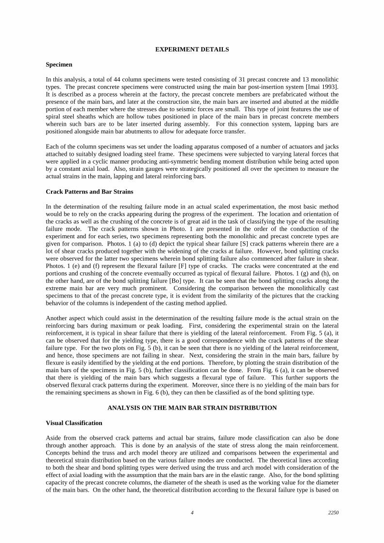
EXPERIMENT DETAILS
Specimen
In this analysis, a total of 44 column specimens were tested consisting of 31 precast concrete and 13 monolithictypes. The precast concrete specimens were constructed using the main bar post-insertion system [Imai 1993].It is described as a process wherein at the factory, the precast concrete members are prefabricated without thepresence of the main bars, and later at the construction site, the main bars are inserted and abutted at the middleportion of each member where the stresses due to seismic forces are small. This type of joint features the use ofspiral steel sheaths which are hollow tubes positioned in place of the main bars in precast concrete memberswherein such bars are to be later inserted during assembly. For this connection system, lapping bars arepositioned alongside main bar abutments to allow for adequate force transfer.
Each of the column specimens was set under the loading apparatus composed of a number of actuators and jacksattached to suitably designed loading steel frame. These specimens were subjected to varying lateral forces thatwere applied in a cyclic manner producing anti-symmetric bending moment distribution while being acted uponby a constant axial load. Also, strain gauges were strategically positioned all over the specimen to measure theactual strains in the main, lapping and lateral reinforcing bars.
Crack Patterns and Bar Strains
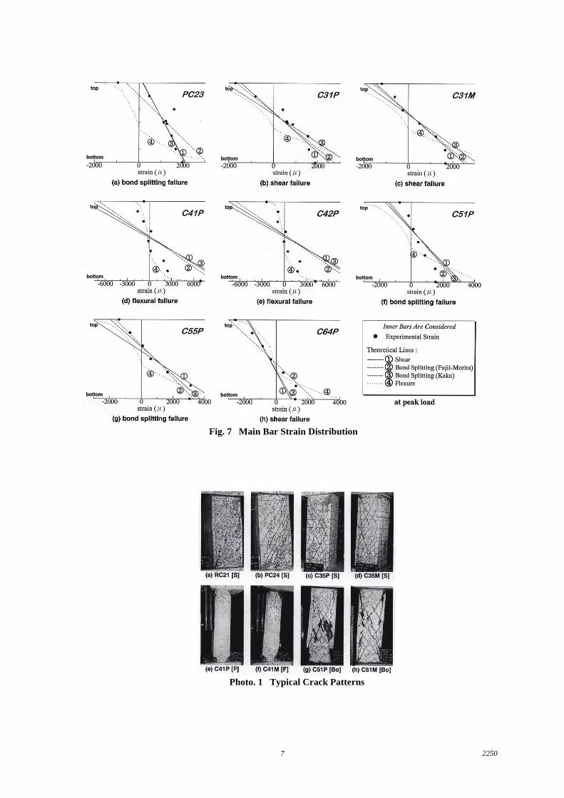
In the determination of the resulting failure mode in an actual scaled experimentation, the most basic methodwould be to rely on the cracks appearing during the progress of the experiment. The location and orientation ofthe cracks as well as the crushing of the concrete is of great aid in the task of classifying the type of the resultingfailure mode. The crack patterns shown in Photo. 1 are presented in the order of the conduction of theexperiment and for each series, two specimens representing both the monolithic and precast concrete types aregiven for comparison. Photos. 1 (a) to (d) depict the typical shear failure [S] crack patterns wherein there are alot of shear cracks produced together with the widening of the cracks at failure. However, bond splitting crackswere observed for the latter two specimens wherein bond splitting failure also commenced after failure in shear.Photos. 1 (e) and (f) represent the flexural failure [F] type of cracks. The cracks were concentrated at the endportions and crushing of the concrete eventually occurred as typical of flexural failure. Photos. 1 (g) and (h), onthe other hand, are of the bond splitting failure [Bo] type. It can be seen that the bond splitting cracks along theextreme main bar are very much prominent. Considering the comparison between the monolithically castspecimens to that of the precast concrete type, it is evident from the similarity of the pictures that the crackingbehavior of the columns is independent of the casting method applied.
Another aspect which could assist in the determination of the resulting failure mode is the actual strain on thereinforcing bars during maximum or peak loading. First, considering the experimental strain on the lateralreinforcement, it is typical in shear failure that there is yielding of the lateral reinforcement. From Fig. 5 (a), itcan be observed that for the yielding type, there is a good correspondence with the crack patterns of the shearfailure type. For the two plots on Fig. 5 (b), it can be seen that there is no yielding of the lateral reinforcement,and hence, those specimens are not failing in shear. Next, considering the strain in the main bars, failure byflexure is easily identified by the yielding at the end portions. Therefore, by plotting the strain distribution of themain bars of the specimens in Fig. 5 (b), further classification can be done. From Fig. 6 (a), it can be observedthat there is yielding of the main bars which suggests a flexural type of failure. This further supports theobserved flexural crack patterns during the experiment. Moreover, since there is no yielding of the main bars forthe remaining specimens as shown in Fig. 6 (b), they can then be classified as of the bond splitting type.
ANALYSIS ON THE MAIN BAR STRAIN DISTRIBUTION
Visual Classification
Aside from the observed crack patterns and actual bar strains, failure mode classification can also be donethrough another approach. This is done by an analysis of the state of stress along the main reinforcement.Concepts behind the truss and arch model theory are utilized and comparisons between the experimental andtheoretical strain distribution based on the various failure modes are conducted. The theoretical lines accordingto both the shear and bond splitting types were derived using the truss and arch model with consideration of theeffect of axial loading with the assumption that the main bars are in the elastic range. Also, for the bond splittingcapacity of the precast concrete columns, the diameter of the sheath is used as the working value for the diameterof the main bars. On the other hand, the theoretical distribution according to the flexural failure type is based on
22505
simple equilibrium and strain compatibility assumptions on the column cross section to include straining beyondthe elastic range. Representative plots according to the resulting failure modes are shown in Fig. 7.
A generally good correspondence is observed with regard to the predicted and actual resulting failure modebased on the actual plots of the main bar strain distributions especially for Figs. 7 (a) to (e) and (g). However,for C51P and C64P in Figs. 7 (f) and (h), there is a little inaccuracy with the observed results. As for specimenC51P, although the experimental main bar strain distribution is closer to the predicted failure line, there is greatoffset observed. The figure shows that the main bar can be stresses a little further before failure. However,failure occurred at a lower strain level which proves an overestimation on the calculated bond splitting capacity.It is inferred that the calculated value using the given bond splitting capacity equation is generally overestimatedfor specimens having a combination of the use of high strength lateral reinforcement and a low lateralreinforcement ratio. Moreover, for specimen C64P, instead of an overestimation, an underestimation on both thecalculated shear and bond splitting capacities were observed. This general behavior is typical of high strengthconcrete specimens wherein there is a low estimate of the calculated strengths especially for the shear failuremode. Therefore, additional studies are necessary with regard to these aspects.
Error Analysis
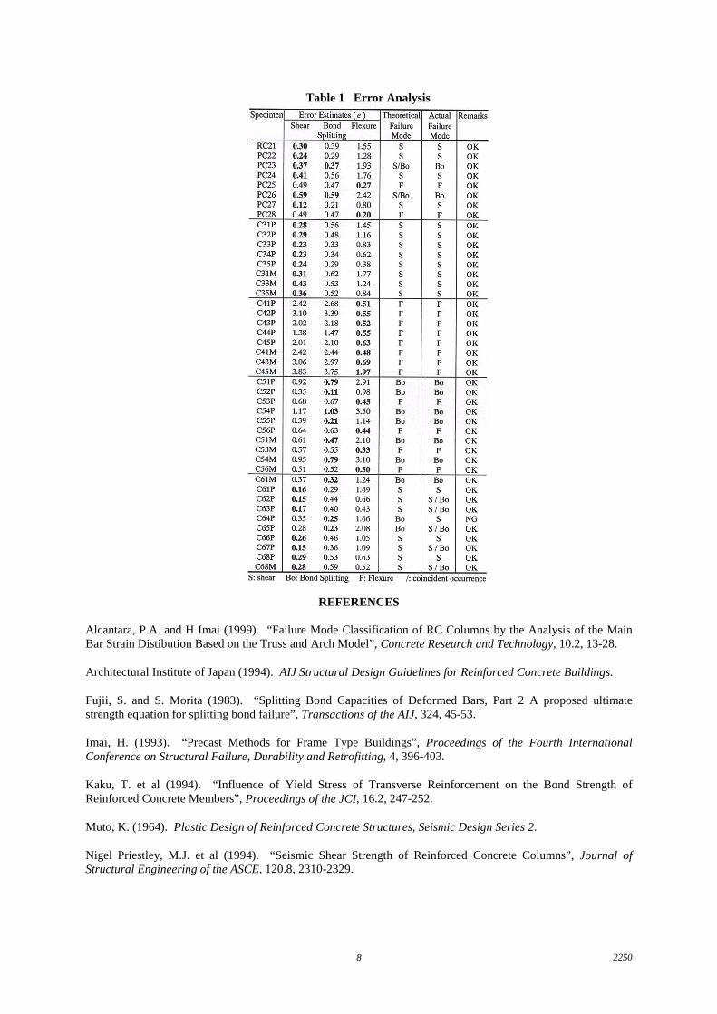
Aside from the visual determination of classifying failure modes, a quantitative approach is also possible. Amore systematic procedure is presented wherein error estimates between the experimental and theoretical plotsare determined and the one showing the least error gives the resulting failure mode. This is more reliable incases where there is closeness between the theoretical failure lines especially for the shear and bond splittingtypes. The statistical criteria used is termed the “sum of squares of the errors” or SSE. In this procedure, theerror is determined by the difference between the experimental strain at a point and the theoretical strain on thefailure line at that same point in the main reinforcement. This is done for all points where the actual strains weremeasured experimentally. These values are then squared to eliminate negative errors. Finally, these values areadded to give the SSE. Furthermore, this value can be normalized to an expression showing a percentage errorbetween the experimental and theoretical values by taking the square root of the SSE over the sum of the squaresof the experimental strains. The normalized values of the errors, e, for all the theoretical failure lines aredetermined and compared, wherein the least value would show the resulting failure mode. Table 1 gives thecalculations made for the specimens considered. For the bond splitting type, only the error estimates for thebond splitting failure line using the Kaku equation are shown, since when considering the specimens featuring aclear bond splitting failure from experimentally observed crack patterns and bar strains, much lesser values ofthe error are given by the Kaku equation, which shows better precision than the Fujii-Morita equation.
From Table 1, by considering the least among the error estimates from the different failure modes, a generalagreement between the observed or actual failure mode and the theoretical failure mode is observed. Of the 44specimens considered, good correspondence between the actual and theoretical failure modes is observed for the43 specimens. This shows a high level of precision of the proposed alternative approach in classifying failuremodes. An error estimate of around 0.5 gives a very good correspondence with the actual failure mode. On thecontrary, greater error estimates show an actual main bar strain distribution which is rather distant from thecalculated failure line. This implies either an underestimation or overestimation on the theoretical ultimatestrength of the column as shown by specimens C51P, C54P and C54M. Hence, such observations made on theerror analysis acts as an aid in the improvement of the column design equations especially on the bond splittingaspect. As for the NG remark on specimen C64P, the main reason lies in the underestimation of the calculatedshear and bond splitting capacities, thereby giving a wrong classification on the resulting failure mode.
CONCLUSIONS
This study is focused on the determination of the resulting failure mode based on the truss and arch modeltheory. Using the experimental strains in the main reinforcement and with proper consideration of the presenceof inner main bars and axial loading, it can be concluded that the classification of the resulting failure mode isgenerally accurate for both the qualitative and quantitative aspects. In the case of shear and flexural failure,results show that the use of the main bar strain distribution is fairly good. On the other hand, for the bondsplitting type, an improvement in the calculation of the reinforced concrete column capacity with properconsideration of the inner rows of main reinforcement is deemed necessary.
22506
Fig. 1 Effect of Axial Loading Fig. 2 Equilibrium Conditions
Fig. 3 Truss MechanismFig. 4 Arch Mechanism and Axial
Loading
Fig. 6 Strain Distribution in the MainReinforcement at Peak Load
Fig. 5 Strain Distributions in theLateral Reinforcement at Peak Load
22507
Photo. 1 Typical Crack Patterns
Fig. 7 Main Bar Strain Distribution
22508
REFERENCES
Alcantara, P.A. and H Imai (1999). “Failure Mode Classification of RC Columns by the Analysis of the MainBar Strain Distibution Based on the Truss and Arch Model”, Concrete Research and Technology, 10.2, 13-28.
Architectural Institute of Japan (1994). AIJ Structural Design Guidelines for Reinforced Concrete Buildings.
Fujii, S. and S. Morita (1983). “Splitting Bond Capacities of Deformed Bars, Part 2 A proposed ultimatestrength equation for splitting bond failure”, Transactions of the AIJ, 324, 45-53.
Imai, H. (1993). “Precast Methods for Frame Type Buildings”, Proceedings of the Fourth InternationalConference on Structural Failure, Durability and Retrofitting, 4, 396-403.
Kaku, T. et al (1994). “Influence of Yield Stress of Transverse Reinforcement on the Bond Strength ofReinforced Concrete Members”, Proceedings of the JCI, 16.2, 247-252.
Muto, K. (1964). Plastic Design of Reinforced Concrete Structures, Seismic Design Series 2.
Nigel Priestley, M.J. et al (1994). “Seismic Shear Strength of Reinforced Concrete Columns”, Journal ofStructural Engineering of the ASCE, 120.8, 2310-2329.
Table 1 Error Analysis