Embed Size (px)
Citation preview

Research Bulletin, Vol. 1 (March 2008) 1
AdministrationDeanProfessor Dr. Mohd Marzuki Mustafa
Deputy Dean (Postgraduate, Student Affairs & Alumni)Professor Dr. Azah MohamedDeputy Dean (Undergraduate, Development &Internationalization)Professor Ir. Dr. Riza Atiq Abdullah OK Rahmat(until 24th February 2008)Deputy Dean (Research)Professor Ir. Dr. Abdul Wahab MohammadHead, Quality ManagementAssoc. Professor Dr. Norhamidi MuhamadHead, Department of Civil and Structural EngineeringAssoc. Professor Ir. Dr. Zamri ChikHead, Department of Electric, Electronic and SystemsEngineeringProf. Dr. Aini HussainHead, Department of Chemical and Process EngineeringAssoc. Professor Dr. Mohd Sobri TakriffHead, Department of Mechanical and Materials EngineeringProfessor Dr. Ahmad Kamal Ariffin Mohd IhsanHead, Department of ArchitectureProfessor Dr. Muhammad Fauzi Mohd ZainHead, Unit of Fundamental Engineering StudiesAssoc. Professor Dr. Azami ZaharimSenior Assistant RegistrarMs. Rosafizah Mohamed IdrusAssistant RegistrarMs. Zaharah Zainal
Board of EditorialChief EditorProfessor Ir. Dr. Abdul Wahab MohammadEditorsProfessor Dr. Mohd Raihan TahaProfessor Dr. Muhammad Fauzi Mohd ZainAssoc. Professor Dr. Siti Masrinda TasirinDr. Taib Iskandar MohamadDr. Mohd Syuhaimi Ab. RahmanMr. Abdul Halim Bin IsmailArrangementMs.Roslena Binti Md ZainiDesignerMr. Mazlan Mohd TahirSecretaryMs. Sukmawati Binti Mohd Said
The Research Bulletin is published twice a year by the Advanced EngineeringCenter, Faculty of Engineering, UKM. We are pleased to invite Faculty membersto contribute their articles to our bulletin. Articles can be submitted to:
Advanced Engineering CenterFaculty of EngineeringUniversiti Kebangsaan Malaysia43600 UKM Bangi, Selangor Darul Ehsan, MALAYSIATel: 603-8921 6454/6451Fax: 603-8925 2546Email: [email protected]/[email protected]
Editorial Note
From The DeanFaculty of Engineering
An electronic version of the Research Bulletin and guidelines to authors can bearchived at www.pkukmweb.ukm.my/~pkt
I would like to congratulate theeditorial team for this inauguralissue “INNOVATE”, the researchbulletin for the Faculty ofEngineering UKM. In this era ofUKM as a research university(RU), research activities shouldbe a priority for all academic staff.Towards this end, the Faculty members have been working hard toobtain research grants from various sources and to produce researchoutputs that would be of high standards. Last year alone, the Facultymembers managed to secure grants worth more than RM 30 millionfrom various sources.
INNOVATE is meant to report these achievements twice a year sothat the outside communities will have the opportunity to read anddiscover the research that are on-going in the faculty. I would like toinvite other interested parties from the industry, research institutionand academia to collaborate with us on this exciting journey.
Thank you.
INNOVATE is intended to play an active role to communicate researchfindings from The Faculty of Engineering UKM to other interestedparties within UKM as well as the public. It will be published twiceyearly starting from March 2008 and will report the research activitiesof the past six preceding months. Apart from reporting the activities,INNOVATE will also contain extended abstract of research reports/articles, abstract of PhD thesis, and general articles. I would like toinvite all researchers from The Faculty of Engineering UKM to contributearticles to make INNOVATE a dynamic means of communicatingresearch outputs. The editorial committee reserves the right to selectarticles on information submitted for publication.
Under the Research University status, the Faculty has identified 24research groups within the Faculty that will spearhead the researchactivities. Faculty members also participate within research groupsin various institutes in UKM such as SERI, IMEN, ANGKASA and SelFuel. With the abundance of research money from various sources,the quality of research within the Faculty should increase and theeditorial team of INNOVATE will make sure that the achievements bereported and disseminated to the interested parties immediately.
We are looking forward to an exciting year ahead!.
Chief Editor
Assalamualaikum Wbt
2 Research Bulletin, Vol. 1 (March 2008)
CONTENT
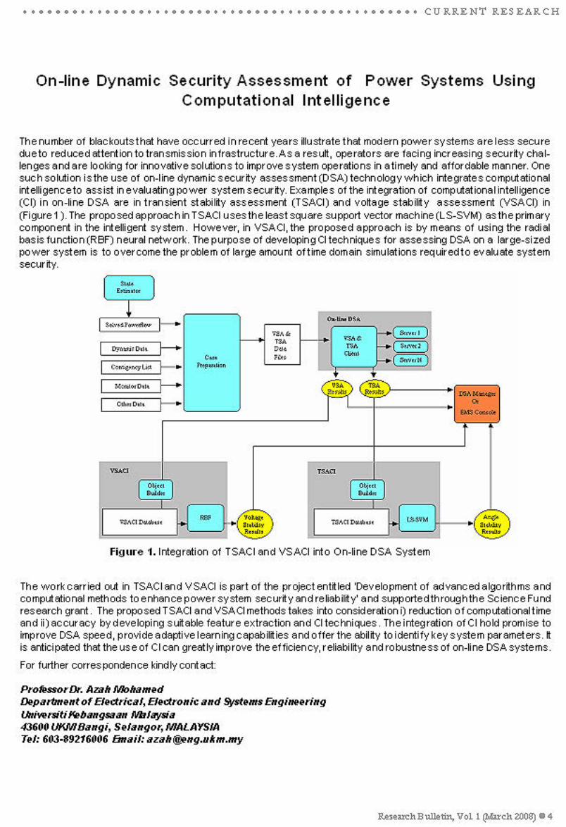
On-line Dynamic Security Assessment of Power Systems Using Computational Intelligence
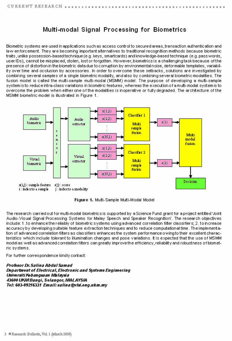
Multi-modal Signal Processing for Biometrics
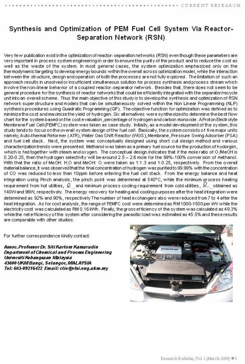
Synthesis and Optimization of PEM Fuel Cell System Via Reactor-Separation Network (RSN)
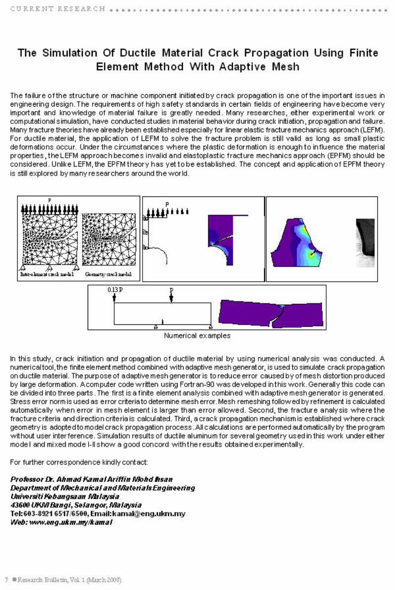
The Simulation Of Ductile Material Crack Propagation Using Finite Element Method WithAdaptive Mesh
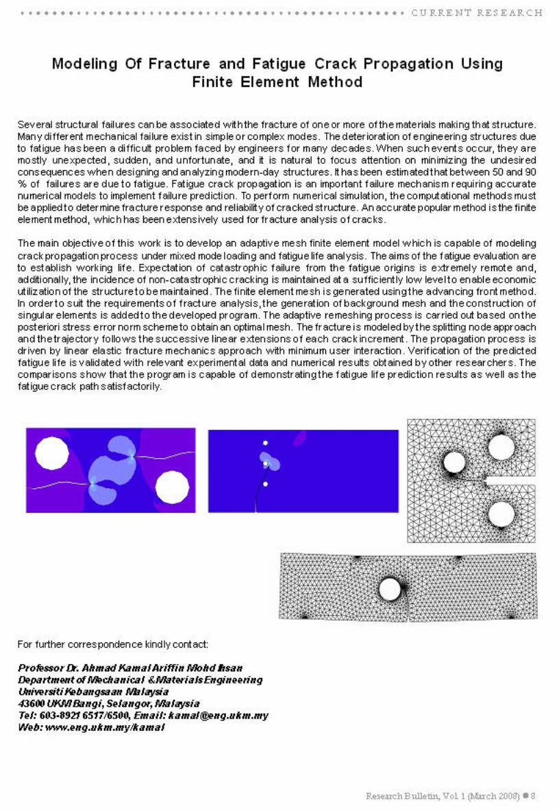
Modeling Of Fracture and Fatigue Crack Propogation Using Finite Element Method
Applications of Nanomaterials in Civil Engineering and Infrastructure Engineeering
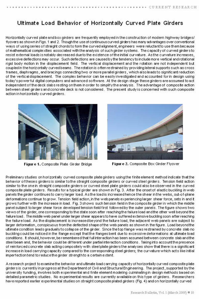
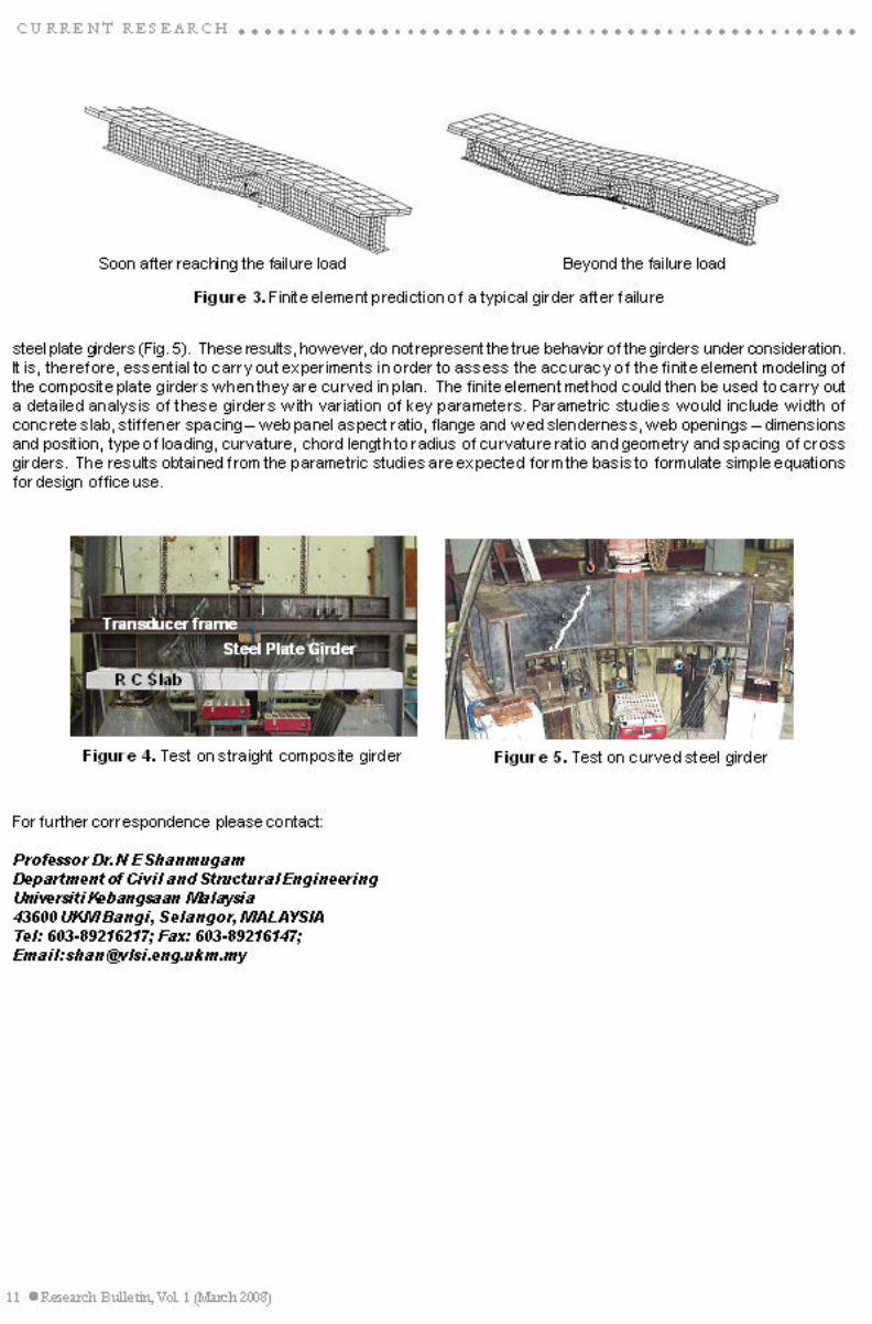
Ultimate Load Behavior of Horizontally Curved Plate Girders
Formulating and Detecting Additive and Innovational Outliers in BL(1,0,1,1) Model for Environ-mental Data
Boundary Layer Flows and Heat Transfer in Thermally Stratified Fluids and Porous Medium
CURRENT RESEARCH
TECHNICAL ABSTRACT
Palm Oil Mill Effluent (POME) Treatment and Bioresources Recovery Using UltrafiltrationMembrane: Effect of Pressure One Membrane Fouling
Intelligent Sorting (I-Sort) System for Plastic Recycling
An Intelligent Power Quality Monitoring Equipment for Automated Recognition of Disturbances
A UMACE Filter-based Biometric Speaker Authentication System Using the Multi-sampleMulti-source Approach
Wavelet Analysis Applied To Seismic Surface Waves For In Situ Attenuation Of Layered SoilMedium
Urban Renewal and Design for Backlanes of Commercial Buildings in City Centres
Extension of Time According To Standard Form of Building Contract
The Development of a Sustainably Responsive Ultra Low Energy Terrace HousingArchitecture for the Tropics Incorporating the Raised Floor Innovation
How Representation of Surface Constructibility Affects CAD Usage in Architecturel Practices
○ ○ ○ ○ ○ ○ ○ ○ ○ ○ ○ ○ ○ ○ ○ ○ ○ ○ ○ ○ ○ ○ ○ ○ ○ ○ ○ ○ ○ ○ ○ ○ ○ ○ ○ ○ ○ ○ ○ ○ ○ ○I N S I D E R E S E A R C H B U L L E T I N
RESEARCH GROUP ACTIVITIES
Advanced Semiconductor Packaging (ASPAC) Research Group
Fuel Injector for CNGDI Engine
CNGDI Engine for Light Duty Vehicles
New Traffic Management System
4
5
6
7
8
9
10-11
12-13
14
15-16
17
18
19
20-22
23-24
25-26
27-28
29-30
31-32
33-34
35-37
38-40
Research Bulletin, Vol. 1 (March 2008) 3
ABSTRACT OF PhD THESIS 2007
Analysis and Prediction of The Ionospheric Disturbances During Solar Eclipse andGeomagnetic Eclipse and Geomagnetics Storms Over The Polar Regions
Real-Time Control of Hydraulic Actuator Using Robust Zero Phase Error Digital TrackingControl
Prototype Development of an Integrated Intelligent Safety System for Vehicle Application
Optical Cross Add and Drop Multiplexer
Development of a Silicon and InGaAS Planar P-I-N Photodiode with HN
and HP Electrodes
Development of New Techniques for Locating Source of Disturbances for Enhancing PowerQuality Diagnosis
Smart Antenna System Testbed and Optimal Beamforming Algorithm for 3G Aplications
Development of an Intelligent Distributed Control System for Urban Traffic
Solar Assisted Dehumidification System for Medicinal Herbs
Finite Element Based Durability Assessment for a New Free Piston Linear Engine
Purification of Hydrogen Gas Using Compact Pressure Swing Adsorption System for Fuel Cell
Fabrication of Electrode Assembly for Fuel Cell Using Spraying Method
AWARDS 2007 53 - 56
RESEARCH PROJECTS 2007 57 - 68
○ ○ ○ ○ ○ ○ ○ ○ ○ ○ ○ ○ ○ ○ ○ ○ ○ ○ ○ ○ ○ ○ ○ ○ ○ ○ ○ ○ ○ ○ ○ ○ ○ ○ ○ ○ ○ ○ ○ ○ ○ ○ I N S I D E R E S E A R C H B U L L E T I N
41
42
43
44
45
46
47
48
49
50
51
52


Research Bulletin, Vol. 1 (March 2008) 15
R E S E A R C H G R O U P A C T I V I T I E S
Advanced Semiconductor Packaging (ASPAC) Research Group
The history for advanced semiconductor packaging research group began in 2003. The team was lead by Assoc. Prof.Ibrahim Ahmad by doing a research on Under Bump Metallurgy (UBM). This research project was the first collaborationwithin UKM and On Semiconductor Sdn. Bhd. It was funded by MOSTI based on EA grant in which totaled more thanRM 200K. By the end 2004, the research group for semiconductor packaging in Malaysia has received an enermousresearch grant under RM-8 which totaled more than RM 26 million. There are several government institutions involvedin this research group: Universiti Malaya, SIRIM Berhad and Universiti Kebangsaan Malaysia as the lead institution.RM 13 million of the total research grant was under UKM’s responsibility. This includes advanced equipment purchase,salary for contract staff and graduate researchers and also consultation fees for industrial experts. For now, allresearchers from UKM are trying to centralize the research activities by building up extra laboratory space, programmonitoring and graduate research assistant logistics. More than RM 7 million has been spent in purchasing equipmentand simulation software. All equipment and simulation software are centralized under a laboratory. In early 2007, thisgroup was formalized as Advanced Semiconductor Packaging (ASPAC) Research Group by the Faculty of Engineering,UKM. This group has already received more than RM30K research grant under the research university budget forcontinued research and development in advanced semiconductor packaging in UKM.
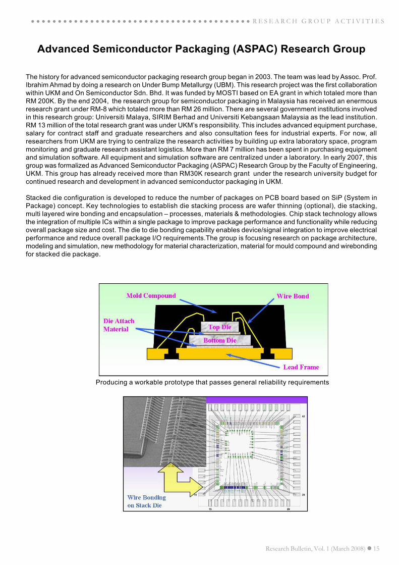
Stacked die configuration is developed to reduce the number of packages on PCB board based on SiP (System inPackage) concept. Key technologies to establish die stacking process are wafer thinning (optional), die stacking,multi layered wire bonding and encapsulation – processes, materials & methodologies. Chip stack technology allowsthe integration of multiple ICs within a single package to improve package performance and functionality while reducingoverall package size and cost. The die to die bonding capability enables device/signal integration to improve electricalperformance and reduce overall package I/O requirements.The group is focusing research on package architecture,modeling and simulation, new methodology for material characterization, material for mould compound and wirebondingfor stacked die package.
Producing a workable prototype that passes general reliability requirements

16 Research Bulletin, Vol. 1 (March 2008)
R E S E A R C H G R O U P A C T I V I T I E S ○ ○ ○ ○ ○ ○ ○ ○ ○ ○ ○ ○ ○ ○ ○ ○ ○ ○ ○ ○ ○ ○ ○ ○ ○ ○ ○ ○ ○ ○ ○ ○ ○ ○ ○ ○ ○ ○ ○ ○
Currently, this group is active in doing research collobaration with industrial partners such as AIC Semiconductor,Freescale, Infineon Technologies, On Semiconductor, Silterra and Shin Etsu. From the collaboration that has beendone, benefits in terms of technologies sharing, ideas and expertise in producing high commercialized product areobtained. With the capability of advanced equipment that has been purchased under IRPA grant has allowed theindustry to solve problems faced by them. This group expects by early 2008, a group of graduate students which areexperts in semiconductor packaging will be produced.
For further correspondence kindly contact:
Assoc. Professor Dr. Ibrahim AhmadDepartment of Electrical, Electronic and Systems EngineeringUniversiti Kebangsaan Malaysia43600 UKM Bangi, Selangor, MALAYSIATel: 603-89216309 Email: [email protected]
The objectives of this research are:
• To develop advance 3-D package particularly stack die QFN package for space saving & system performanceenhancement (faster clock speed)
• To establish new processes, materials and methodologies for wafer thinning (optional), die stacking, multilayered wire bonding and encapsulation
• To produce a workable prototype that passes general reliability requirements
Research Bulletin, Vol. 1 (March 2008) 17
R E S E A R C H G R O U P A C T I V I T I E S
Fuel Injector for CNGDI Engine
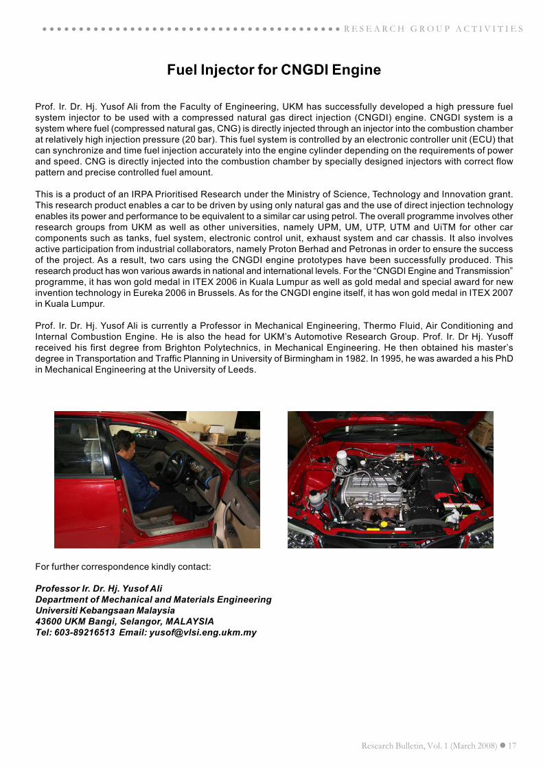
Prof. Ir. Dr. Hj. Yusof Ali from the Faculty of Engineering, UKM has successfully developed a high pressure fuelsystem injector to be used with a compressed natural gas direct injection (CNGDI) engine. CNGDI system is asystem where fuel (compressed natural gas, CNG) is directly injected through an injector into the combustion chamberat relatively high injection pressure (20 bar). This fuel system is controlled by an electronic controller unit (ECU) thatcan synchronize and time fuel injection accurately into the engine cylinder depending on the requirements of powerand speed. CNG is directly injected into the combustion chamber by specially designed injectors with correct flowpattern and precise controlled fuel amount.
This is a product of an IRPA Prioritised Research under the Ministry of Science, Technology and Innovation grant.This research product enables a car to be driven by using only natural gas and the use of direct injection technologyenables its power and performance to be equivalent to a similar car using petrol. The overall programme involves otherresearch groups from UKM as well as other universities, namely UPM, UM, UTP, UTM and UiTM for other carcomponents such as tanks, fuel system, electronic control unit, exhaust system and car chassis. It also involvesactive participation from industrial collaborators, namely Proton Berhad and Petronas in order to ensure the successof the project. As a result, two cars using the CNGDI engine prototypes have been successfully produced. Thisresearch product has won various awards in national and international levels. For the “CNGDI Engine and Transmission”programme, it has won gold medal in ITEX 2006 in Kuala Lumpur as well as gold medal and special award for newinvention technology in Eureka 2006 in Brussels. As for the CNGDI engine itself, it has won gold medal in ITEX 2007in Kuala Lumpur.
Prof. Ir. Dr. Hj. Yusof Ali is currently a Professor in Mechanical Engineering, Thermo Fluid, Air Conditioning andInternal Combustion Engine. He is also the head for UKM’s Automotive Research Group. Prof. Ir. Dr Hj. Yusoffreceived his first degree from Brighton Polytechnics, in Mechanical Engineering. He then obtained his master’sdegree in Transportation and Traffic Planning in University of Birmingham in 1982. In 1995, he was awarded a his PhDin Mechanical Engineering at the University of Leeds.
For further correspondence kindly contact:
Professor Ir. Dr. Hj. Yusof AliDepartment of Mechanical and Materials EngineeringUniversiti Kebangsaan Malaysia43600 UKM Bangi, Selangor, MALAYSIATel: 603-89216513 Email: [email protected]
18 Research Bulletin, Vol. 1 (March 2008)
R E S E A R C H G R O U P A C T I V I T I E S
CNGDI Engine for Light Duty Vehicles
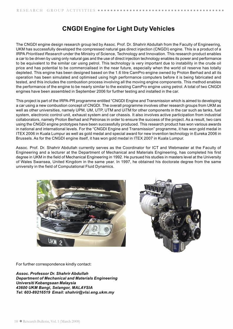
The CNGDI engine design research group led by Assoc. Prof. Dr. Shahrir Abdullah from the Faculty of Engineering,UKM has successfully developed the compressed natural gas direct injection (CNGDI) engine. This is a product of aIRPA Prioritised Research under the Ministry of Science, Technology and Innovation. This research product enablesa car to be driven by using only natural gas and the use of direct injection technology enables its power and performanceto be equivalent to the similar car using petrol. This technology is very important due to instability in the crude oilprice and has potential to be commercialised in the near future, especially when the world oil reserve has totallydepleted. This engine has been designed based on the 1.6 litre CamPro engine owned by Proton Berhad and all itsoperation has been simulated and optimised using high performance computers before it is being fabricated andtested, and this includes the combustion process involving all the moving engine components. This method enablesthe performance of the engine to be nearly similar to the existing CamPro engine using petrol. A total of two CNGDIengines have been assembled in September 2006 for further testing and installed in the car.
This project is part of the IRPA-PR programme entitled “CNGDI Engine and Transmission which is aimed to developinga car using a new combustion concept of CNGDI. The overall programme involves other research groups from UKM aswell as other universities, namely UPM, UM, UTP, UTM and UiTM for other components in the car such as tanks, fuelsystem, electronic control unit, exhaust system and car chassis. It also involves active participation from industrialcollaborators, namely Proton Berhad and Petronas in order to ensure the success of the project. As a result, two carsusing the CNGDI engine prototypes have been successfully produced. This research product has won various awardsin national and international levels. For the “CNGDI Engine and Transmission” programme, it has won gold medal inITEX 2006 in Kuala Lumpur as well as gold medal and special award for new invention technology in Eureka 2006 inBrussels. As for the CNGDI engine itself, it has won gold medal in ITEX 2007 in Kuala Lumpur.
Assoc. Prof. Dr. Shahrir Abdullah currently serves as the Coordinator for ICT and Webmaster at the Faculty ofEngineering and a lecturer at the Department of Mechanical and Materials Engineering, has completed his firstdegree in UKM in the field of Mechanical Engineering in 1992. He pursued his studies in masters level at the Universityof Wales Swansea, United Kingdom in the same year. In 1997, he obtained his doctorate degree from the sameuniversity in the field of Computational Fluid Dynamics.
For further correspondence kindly contact:
Assoc. Professor Dr. Shahrir AbdullahDepartment of Mechanical and Materials EngineeringUniversiti Kebangsaan Malaysia43600 UKM Bangi, Selangor, MALAYSIATel: 603-89216519 Email: [email protected]
Research Bulletin, Vol. 1 (March 2008) 19
R E S E A R C H G R O U P A C T I V I T I E S
New Traffic Management System
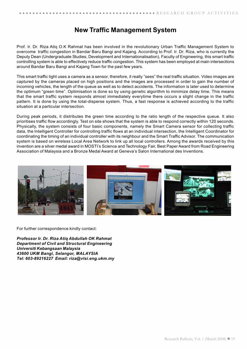
Prof. Ir. Dr. Riza Atiq O.K Rahmat has been involved in the revolutionary Urban Traffic Management System toovercome traffic congestion in Bandar Baru Bangi and Kajang. According to Prof. Ir. Dr. Riza, who is currently theDeputy Dean (Undergraduate Studies, Development and Internationalisation), Faculty of Engineering, this smart trafficcontrolling system is able to effectively reduce traffic congestion. This system has been employed at main intersectionsaround Bandar Baru Bangi and Kajang Town for the past few years.
This smart traffic light uses a camera as a sensor, therefore, it really ”sees” the real traffic situation. Video images arecaptured by the cameras placed on high positions and the images are processed in order to gain the number ofincoming vehicles, the length of the queue as well as to detect accidents. The information is later used to determinethe optimum “green time”. Optimisation is done so by using genetic algorithm to minimize delay time. This meansthat the smart traffic system responds almost immediately everytime there occurs a slight change in the trafficpattern. It is done by using the total-disperse system. Thus, a fast response is achieved according to the trafficsituation at a particular intersection.
During peak periods, it distributes the green time according to the ratio length of the respective queue. It alsoprioritises traffic flow accordingly. Test on site shows that the system is able to respond correctly within 120 seconds.Physically, the system consists of four basic components, namely the Smart Camera sensor for collecting trafficdata, the Intelligent Controller for controlling traffic flows at an individual intersection, the Intelligent Coordinator forcoordinating the timing of an individual controller with its neighbour and the Smart Traffic Advisor. The communicationsystem is based on wireless Local Area Network to link up all local controllers. Among the awards received by thisinvention are a silver medal award in MOSTI’s Science and Technology Fair, Best Paper Award from Road EngineeringAssociation of Malaysia and a Bronze Medal Award at Geneva’s Salon International des Inventions.
For further correspondence kindly contact:
Professor Ir. Dr. Riza Atiq Abdullah OK RahmatDepartment of Civil and Structural EngineeringUniversiti Kebangsaan Malaysia43600 UKM Bangi, Selangor, MALAYSIATel: 603-89216227 Email: [email protected]

Research Bulletin, Vol. 1 (March 2008) 20
○ ○ ○ ○ ○ ○ ○ ○ ○ ○ ○ ○ ○ ○ ○ ○ ○ ○ ○ ○ ○ ○ ○ ○ ○ ○ ○ ○ ○ ○ ○ ○ ○ ○ ○ ○ ○ ○ ○ ○ ○ ○ ○ ○ ○ ○ ○ ○ T E C H N I C A L A B S T R A C T
Palm Oil Mill Effluent (POME) Treatment and BioresourcesRecovery Using Ultrafiltration Membrane:
Effect of Pressure One Membrane Fouling
Abdul Wahab Mohammad, Wu Ta Yeong, Jamaliah Md. Jahim and Nurina AnuarDepartment of Chemical and Process Engineerig
Universiti Kebangsaan Malaysia43600 UKM Bangi, Selangor, MALAYSIATel: 603-8921 6102; Fax: 603-8925 2546
Email: [email protected]
ABSTRACT
Ponding system is the most usual treatment system used by more than 85% of palm oil mills in Malaysia for treatingpalm oil mill effluent (POME). The current treatment system, which is based mainly on biological treatment ofanaerobic and aerobic systems, is quite inefficient and this unfortunately leads to environmental pollution issues. Adetailed cost calculation for Indonesia also shows that the conventional system of POME treatment, such as theponding system, is not only the system with the highest pollution of the environment, the lowest utilization of renewableresources and also the system with the lowest profit. This paper suggests the use of ultrafiltration (UF) membrane inbetter management of POME either in the aspect of treatment or recovery of bioresources, namely protein andcarbohydrate from POME. This paper also examines the effect of applied pressure on membrane fouling that mightinfluence the potential use of UF. POME was first subjected to physical pretreatment processes, consisting of depthand surface filtration in order to remove the total suspended solids (TSS). Then, polysulphone UF membrane of 20kDa was used in the UF membrane study. This study indicated that the applied pressure imposed a direct effect onfouling, permeate flux, protein and carbohydrate recovery as well as wastewater treatment. In total, the permeate fluxdecreased with filtration time until it reached steady-state values. The highest applied pressure (0.8 MPa) encouragedthe formation of fouling up to 85.8% but at the same time enabled the recovery of protein and carbohydrate up to61.4% and 76.4%, respectively. The highest reduction of TSS, turbidity, total dissolved solids (TDS) and chemicaloxygen demand (COD) also occurred at 0.8 MPa up to 97.7%, 88.5%, 6.5% and 57.0%. This study revealed that it ispossible to have appropriate control of applied pressure in order to favor fouling that would, in turn, lead to betterrejection of other solutes present in the feed.
Keywords: hybrid organic-inorganic membrane, PMMA/TEOS, sol-gel, structure
INTRODUCTION
Raw palm oil mill effluent (POME) is a colloidalsuspension containing 95-96% water, 0.6-0.7% oil and4-5% total solids including 2-4% suspended solidsthat are mainly consisted of debris from palm fruitmesocarp generated from three main sources, namelys ter i l i ze r condensate , separa tor s ludge andhydrocyclone wastewater (Ma, 2000). If the effluent isd ischarged un t rea ted , i t can cer ta in ly causeconsiderable environmental problems (Davis and Reilly,1980) due to its high biochemical oxygen demand(25,000 mg/l), chemical oxygen demand (53,630 mg/l), oil and grease (8,370 mg/l), total solids (43,635mg/l) as well as suspended solids (19,020 mg/l) (Ma,1995). Therefore, the palm oil mill industry in Malaysiais identified as the one that produces the largestpollution load into the rivers throughout the country(Hwang, et al. 1978). On the other hand, the notion ofnurturing POME and its derivatives as valuableresources should not be dismissed. This is becausePOME contains high concentrat ions of protein,carbohydrate, nitrogenous compounds, lipids and
minerals (Habib, et al. 1997) that may be convertedinto useful materials using microbial processes(Agamuthu and Tan, 1985).
In the last decade, ultrafi ltration (UF) has beensuccessfully developed from a useful laboratory toolto an industrial process, including production of purewater, fractionation or concentration steps in the food,pharmaceutical and biotechnological industries as wellas treatment of wastewater. However, membranefou l ing , wh ich is de f ined as depos i t ion andaccumulation of constituents in the feed stream onthe membrane, may occur during the separationprocess using UF membrane. This fouling resistancemay be due to several mechanisms including gel layerformation, adsorption and pore plugging, which are difficultto differentiate although adsorption-related pore pluggingis important in larger pore membranes (Clark, et al.1991). The membrane fouling causes an increase in themembrane cleaning cost, process down time and alsomembrane damage due to the frequency and harshnessof cleaning condition (Maartens, et al. 2002). On thecontrary, membrane fouling may be used advantageously
21 Research Bulletin, Vol. 1 (March 2008)
○ ○ ○ ○ ○ ○ ○ ○ ○ ○ ○ ○ ○ ○ ○ ○ ○ ○ ○ ○ ○ ○ ○ ○ ○ ○ ○ ○ ○ ○ ○ ○ ○ ○ ○ ○ ○ ○ ○ ○ ○ ○ ○ ○ ○ ○ ○ ○T E C H N I C A L A B S T R A C T
RESULTS AND DISCUSSION
Effect of applied pressure on permeate flux andfouling
The performance of polysulphone membrane with MWCOof 20,000 was tested at different applied pressure. Ingeneral, the results illustrate that the increase in appliedpressure led to an increase in both the initial and finalflux values. These data are in agreement with the find-ings of Mohammadi et al. (2003) and Ahmad et al. (2005).Based on Darcy’s law, the increasing pressure gradientincreases permeate flux.
However, an increase in applied pressure could also at-tribute to membrane fouling (Cheryan, 1998). The per-meate flux reduced drastically with time of operation,which was rapid in the initial time period followed by amore gradual decline as indicated. This is the trend gen-erally observed during the fouling of sorptive membranesuch as polysulphone membrane in the sample (pre-treated POME contains 7.05 g/l protein) that containedconsiderable amount of protein (Nakatsuka and Michaels,1992). For the polysulphone membrane, it is apparentthat rapid flux decline is a consequence of both perme-ability reduction due to adsorption of protein on the purewalls and formation of a low-hydraulic-permeability layerof retained protein on the membrane surface (Nakatsukaand Michaels, 1992).
In order to study the fouling behavior during UF ofpretreated POME at different applied pressure, simplefouling experiments were done. As expected, the greatestfouling occurred at the highest applied pressure(Nakatsuka and Michaels, 1992) of 0.8 MPa with foulingup to 85.8%, followed by applied pressure of 0.6, 0.4,and 0.2 MPa with fouling up to 83.7, 81.9 and 75.1%,respectively. The adsorption of available protein (inpretreated POME in this study) to membrane surfacescan lead to the formation of a fouling layer, whichdrastically reduces permeate flux and represents a seriousimpediment to efficient UF operations (Clark, et al. 1991).
Effect of applied pressure on quality of permeateand fouling
In general, more than 95% of total suspended solids orTSS could be reduced by UF regardless of applied pres-sure, though the highest reduction of TSS (up to 97.7%)happened at the highest applied pressure of 0.8 MPa.Similar result was also observed in the study carried outby Ahmad et al. (2005), who claimed that UF membranewas able to reject TSS exceeding 96% in the pretreatedPOME.
The turbidity of pretreated POME after undergoing UFwas further reduced, with up to 88.5% turbidity reductioncould be observed at the highest pressure of 0.8 MPabut lowest turbidity reduction (78.3%) at 0.2 MPa. Thepercentage reduction of total dissolved solids or TDS wasproven to be low and insignificant in the range of appliedpressure, with the maximum reduction of TDS (6.5%) at0.8 MPa. This is because UF membrane was suitable forextensively removing TSS content, but it had difficulty inremoving dissolved organics (Oe, et al. 1996; Ahmad, etal. 2005).
Effect of applied pressure on protein andcarbohydrate recovery and fouling
From the results obtained, the protein and carbohydraterecovery increased in line with the increasing of appliedpressure, with the highest recovery of protein (61.4%)and carbohydrate (76.4%) happened at 0.8 MPa. Theseresults indicated that solute rejection was greater at thehigher filtration pressure, in qualitative agreement withthe classical (Spiegler-Kedem) convection/diffusion modelfor solute transport, which predicts that solute rejectionby a partially retentive membrane should increase withtransmembrane solvent flux (Nakatsuka and Michaels,1992).
According to Nakatsuka and Michaels (1992), thesecondary deposited protein layer formed at low pressurewas quite fragile but the layer formed at the higherpressure was stable to disruption. Therefore, UF at lowpressure might prevent protein deposition and lower thecompression of the protein deposit, resulting in smallerrecovery or rejection of solutes (van Oers, et al. 1995).This explains the reason why the recovery of both protein(45.0%) and carbohydrate (66.0%) were the lowest atthe applied pressure of 0.2 MPa.
in the simultaneous concentration and purification of adeposit-forming solute (Wu, et al. 2007).
STUDY OBJECTIVE
The main objective of the present study was to investigatethe effect of applied pressure (0.2-0.8 MPa) on membranefouling in relationship to the potential use of polysulphoneUF membrane of 20,000 MWCO in treating and recoveringboth protein and carbohydrate in the POME, in whichcase the recovered bioresources were proven to be ausable fermentation substrate (Wu, et al. 2006).
MATERIALS AND METHODS
Detailed methodology for this study has been reportedelsewhere (Wu et al, 2007)
CONCLUSIONS AND FINDINGS
One of the critical issues for the successful applicationof UF in protein and carbohydrate recovery as well aswastewater treatment is membrane fouling due to theprotein and other dissolved organic matter, whichnegatively affects productivity, product quality and processcosts. However, results obtained in this study found thatthe fouling occurred not only enhanced the recovery ofprotein and carbohydrate but also improved the treatment
Research Bulletin, Vol. 1 (March 2008) 22
○ ○ ○ ○ ○ ○ ○ ○ ○ ○ ○ ○ ○ ○ ○ ○ ○ ○ ○ ○ ○ ○ ○ ○ ○ ○ ○ ○ ○ ○ ○ ○ ○ ○ ○ ○ ○ ○ ○ ○ ○ ○ ○ ○ ○ ○ ○ ○ T E C H N I C A L A B S T R A C T
of pretreated POME.
This study also indicated that the applied pressureimposed direct and significant effects on fouling, permeateflux, protein and carbohydrate recovery as well aswastewater treatment. The fouling could be observed fromthe decline in permeate flux with filtration time. Thegreatest fouling, up to 85.8%, occurred at the highestapplied pressure of 0.8 MPa in UF operation, allowingthe highest recovery of protein and carbohydrate up to61.4% and 76.4%, respectively. In general, the highestreduction of TSS, turbidity, TDS and COD also occurredat 0.8 MPa up to 97.7%, 88.5%, 6.5% and 57.0%,respectively, although the reduction of TSS and TDS didnot vary significantly among the other pressure. If it isthe objective to retain the lower molecular solutes in theretentate and for better wastewater treatment, thecompression of the protein layer and/or pore plugging athigher pressure can be used in a positive sense toincrease the recovery of the solutes, thereby reducingthe environmental risks from the effluent.
REFERENCES
Agamuthu P. dan Tan E.L. 1985. Digestion of dried palm oilmill effluent by Cellulomonas sp. Microbiol. Lett. 30: 109-113.
Ahmad A.L., Ismail S. dan Bhatia S. 2005. Ultrafiltrationbehavior in the treatment of agro-industry effluent: Pilot scalestudies. Chem. Eng. Sci. 60: 5385-5394.
Clark W.M., Bansal A., Sontakke M. dan Ma Y.H. 1991. Proteinadsorption and fouling in ceramic ultrafiltration membranes.J. Membr. Sci. 55: 21-38.
Cheryan M. 1998. Ultrafiltration and Microfiltration Handbook.Technomic Publishing Co, Lancaster PA, USA.
Davis J.B. dan Reilly P.J.A. 1980. Palm oil mill effluent – asummary of treatment methods. Oleagineux. 35: 323-330.
Dubois M., Gilles K.A., Hamilton J.K., Rebers P.A. dan SmithF. 1956. Colorimetric method for determination of sugarsand related substances. Anal. Chem. 28: 350-356.
Habib M.A.B., Yusoff F.M., Phang S.M., Ang K.J. dan MohamedS. 1997. Nutritional values of chironomid larvae grown inpalm oil mill effluent and algal culture. Aquaculture. 158:95-105.
Hwang T.K., Ong S.M., Seow C.C. dan Tan H.K. 1978.Chemical composition of palm oil mill effluents. Planter. 54:749–756.
Kerkhof P.J.A.M. dan Schoutens G.H. 1988. Membraneprocessing of industrial enzymes, in: Bruin S. (Ed.),Preconcentration and Drying of Food Materials. Elsevier: 87.Amsterdam.
Lowry O.H., Rosebrough N.J., Farr A.L. dan Randall R.J.1951. Protein measurement with the folin phenol reagent.J. Biol. Chem. 193: 265-275.
Ma A.N. 1995. A novel treatment for palm oil mill effluent.Palm Oil Research Institude of Malaysia (PORIM). 29: 201-212.Ma A.N. 2000. Environmental management for the palm oilindustry. Palm Oil Developments. 30 : 1-10.
Maartens A., Jacobs E.P. dan Swart P. 2002. Ultrafiltration ofpulp and paper effluent: membrane fouling – prevention andcleaning, J. Membr. Sci. 209: 81-92.
Mohammad A.W., Abdul Rahman R. dan Wu T.Y. 2002.Potential use of nanofiltration membranes for cleanerproduction. Second Seminar on Water Management, JSPSProgramme. Kyoto University.
Mohammadi T., Moghadam M.K. dan Madaeni S.S. 2003.Hydrodynamic factors affecting flux and fouling duringreverse osmosis of seawater. Desalination 151: 239-245.
Nakatsuka S. dan Michaels A.S. 1993. Transport andseparation of proteins by ultrafiltration through sorptive andnon-sorptive membranes. J. Membr. Sci. 69: 189-211.
Oe T., Koide H., Hirokawa H. dan Okukawa K. 1996.Performance of membrane filtration system used for watertreatment. Desalination. 106: 107-113.
Wu T.Y., Mohammad A.W., Md. Jahim J. dan Anuar N. 2006.Investigations on protease production by a wild-typeAspergillus terreus strain using diluted retentate of pre-filtered palm oil mill effluent (POME) as substrate. EnzymeMicrob. Technol. 39: 1223-1229.
Detailed results of this study has been reported in:
Wu T.Y., Mohammad A.W., Md. Jahim J. dan Anuar N. 2007.Palm oil mill effluent (POME) treatment and bioresourcesrecovery using ultrafiltration membrane: Effect of pressureon membrane fouling. Biochem. Eng. J. 35: 309-317.
23 Research Bulletin, Vol. 1 (March 2008)
○ ○ ○ ○ ○ ○ ○ ○ ○ ○ ○ ○ ○ ○ ○ ○ ○ ○ ○ ○ ○ ○ ○ ○ ○ ○ ○ ○ ○ ○ ○ ○ ○ ○ ○ ○ ○ ○ ○ ○ ○ ○ ○ ○ ○ ○ ○ ○T E C H N I C A L A B S T R A C T
Intelligent Sorting (I-Sort) System for Plastic Recycling
Dzuraidah Abd. Wahab, Edgar Scavino, Hassan Basri, Mohd Marzuki Mustafaand Aini Hussain
Smart Engineering System Research LaboratoryFaculty of Engineering
Universiti Kebangsaan Malaysia43600 UKM Bangi, Selangor, MALAYSIA
Tel: 603-89216322; Fax: 603-89216146Email: [email protected]
ABSTRACT
The manual sorting process deployed in many plastic recycling facilities poses several setbacks to the efficiency ofrecycling industry. Apart from the unhygienic working environment and inconsistencies in detection results and hazardousdetection methods, the manual sorting process has been plagued by high operator turnover. This technical paperpresents the development of an automated sorting prototype system at the Faculty of Engineering, UniversityKebangsaan Malaysia. The developed system is capable of providing an efficient yet cost effective method to sortdomestic recyclables.
Keywords: plastic recycling, automated sorting, image processing
INTRODUCTION
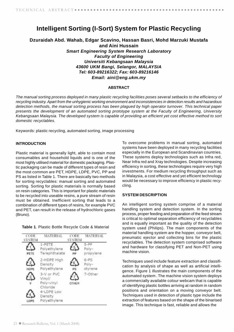
Plastic material is generally light, able to contain mostconsumables and household liquids and is one of themost highly utilised material for domestic packaging. Plas-tic packaging can be made of different types of resin andthe most common are PET, HDPE, LDPE, PVC, PP andPS as listed in Table 1. There are basically two methodsfor sorting recyclables: manual sorting and automatedsorting. Sorting for plastic materials is normally basedon resin categories. This is important for plastic materialsto be recycled into useable resins, a pure stream of resinmust be obtained. Inefficient sorting that leads to acombination of different types of resins, for example PVCand PET, can result in the release of hydrochloric gases(Bruno).
Table 1. Plastic Bottle Recycle Code & Material
To overcome problems in manual sorting, automatedsystems have been deployed in many recycling facilitiesespecially in the European and Scandinavian countries.These systems deploy technologies such as Infra red,Near Infra red and Xray technologies. Despite increasingefficiency in sorting, these technologies require very highinvestments. For medium recycling throughput such asin Malaysia, a cost effective and yet efficient technologywould be necessary to improve efficiency in plastic recy-cling.
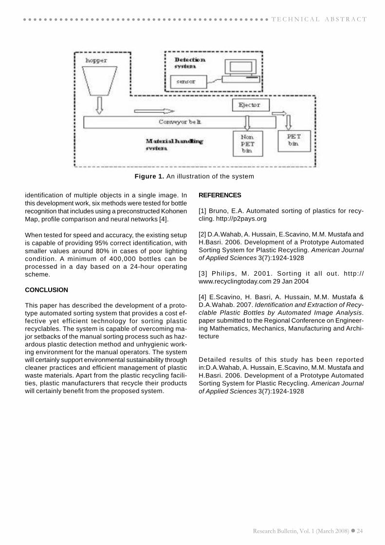
SYSTEM DESCRIPTION
An intelligent sorting system comprise of a materialhandling system and detection system. In the sortingprocess, proper feeding and preparation of the feed streamis critical to optimal separation efficiency of recyclablesand is equally important as the quality of the detectionsystem used (Philips). The main components of thematerial handling system are the hopper, conveyor belt,pneumatic ejector and collecting bins for the plasticrecyclables. The detection system comprised softwareand hardware for classifying PET and Non-PET usingmachine vision.
Techniques used include feature extraction and classifi-cation by analysis of shape as well as artificial intelli-gence. Figure 1 illustrates the main components of theautomated system.The machine vision system deploysa commercially available colour webcam that is capableof identifying plastic bottles arriving at random in randompositions and orientation on a moving conveyor belt.Techniques used in detection of plastic type include theextraction of features based on the shape of the binarisedimage. This technique is fast, reliable and allows the
Research Bulletin, Vol. 1 (March 2008) 24
○ ○ ○ ○ ○ ○ ○ ○ ○ ○ ○ ○ ○ ○ ○ ○ ○ ○ ○ ○ ○ ○ ○ ○ ○ ○ ○ ○ ○ ○ ○ ○ ○ ○ ○ ○ ○ ○ ○ ○ ○ ○ ○ ○ ○ ○ ○ ○ T E C H N I C A L A B S T R A C T
Figure 1. An illustration of the system
identification of multiple objects in a single image. Inthis development work, six methods were tested for bottlerecognition that includes using a preconstructed KohonenMap, profile comparison and neural networks [4].
When tested for speed and accuracy, the existing setupis capable of providing 95% correct identification, withsmaller values around 80% in cases of poor lightingcondition. A minimum of 400,000 bottles can beprocessed in a day based on a 24-hour operatingscheme.
CONCLUSION
This paper has described the development of a proto-type automated sorting system that provides a cost ef-fective yet efficient technology for sorting plasticrecyclables. The system is capable of overcoming ma-jor setbacks of the manual sorting process such as haz-ardous plastic detection method and unhygienic work-ing environment for the manual operators. The systemwill certainly support environmental sustainability throughcleaner practices and efficient management of plasticwaste materials. Apart from the plastic recycling facili-ties, plastic manufacturers that recycle their productswill certainly benefit from the proposed system.
REFERENCES
[1] Bruno, E.A. Automated sorting of plastics for recy-cling. http://p2pays.org
[2] D.A.Wahab, A. Hussain, E.Scavino, M.M. Mustafa andH.Basri. 2006. Development of a Prototype AutomatedSorting System for Plastic Recycling. American Journalof Applied Sciences 3(7):1924-1928
[3] Phi l ips, M. 2001. Sort ing i t al l out. ht tp: / /www.recyclingtoday.com 29 Jan 2004
[4] E.Scavino, H. Basri, A. Hussain, M.M. Mustafa &D.A.Wahab. 2007. Identification and Extraction of Recy-clable Plastic Bottles by Automated Image Analysis.paper submitted to the Regional Conference on Engineer-ing Mathematics, Mechanics, Manufacturing and Archi-tecture
Detailed results of this study has been reportedin:D.A.Wahab, A. Hussain, E.Scavino, M.M. Mustafa andH.Basri. 2006. Development of a Prototype AutomatedSorting System for Plastic Recycling. American Journalof Applied Sciences 3(7):1924-1928
25 Research Bulletin, Vol. 1 (March 2008)
○ ○ ○ ○ ○ ○ ○ ○ ○ ○ ○ ○ ○ ○ ○ ○ ○ ○ ○ ○ ○ ○ ○ ○ ○ ○ ○ ○ ○ ○ ○ ○ ○ ○ ○ ○ ○ ○ ○ ○ ○ ○ ○ ○ ○ ○ ○ ○T E C H N I C A L A B S T R A C T
An Intelligent Power Quality Monitoring Equipment forAutomated Recognition of Disturbances
Mohammed E Salem, Azah Mohamed and Salina Abdul SamadDepartment of Electrical, Electronic and Systems Engineering
Universiti Kebangsaan Malaysia43600 UKM Bangi, Selangor, MALAYSIA
Tel: 603-89216006; Email: [email protected]
ABSTRACT
To achieve real-time detection and classification of power quality (PQ) disturbances, an intelligent PQ monitoringequipment with capability of identifying the disturbance type based on the voltage waveform pattern is proposed. Thispaper presents the development of a DSP-based hardware PQ monitoring equipment for real-time disturbance detectionand classification using the S-transform and the rule based expert system, respectively. The S-transform which isprogrammed in DSP is used to detect the various types of disturbances such as voltage sag, swell, transient,notching, interruption and harmonic while the rule based expert system is used to classify the disturbance type. Testresults proved that this intelligent monitoring equipment can meet the requirement of the modern PQ monitoringsystem.
Keywords: power quality, monitoring instrument, DSP, S-transform, expert system
INTRODUCTION
The increasing importance of electric power quality (PQ)has led to the development of various types of PQmonitoring instruments. However, there is a need for aPQ monitoring instrument that can be used to performfast and accurate detection of power disturbances.Accurate measurement of power disturbances in real timecircumstances is important for PQ monitoring, mitigationand control in power systems (Lin & Domijan, 2006). Areal time PQ monitor should be able to acquire voltageand current waveforms, identify the disturbances from theabnormalities detected and thereby understand thecauses of the disturbances. To perform all these functionsin real time, there has to be special hardware with massivecomputing power, sophisticated software to analyze thedata using advanced signal processing and artificialintelligent techniques.
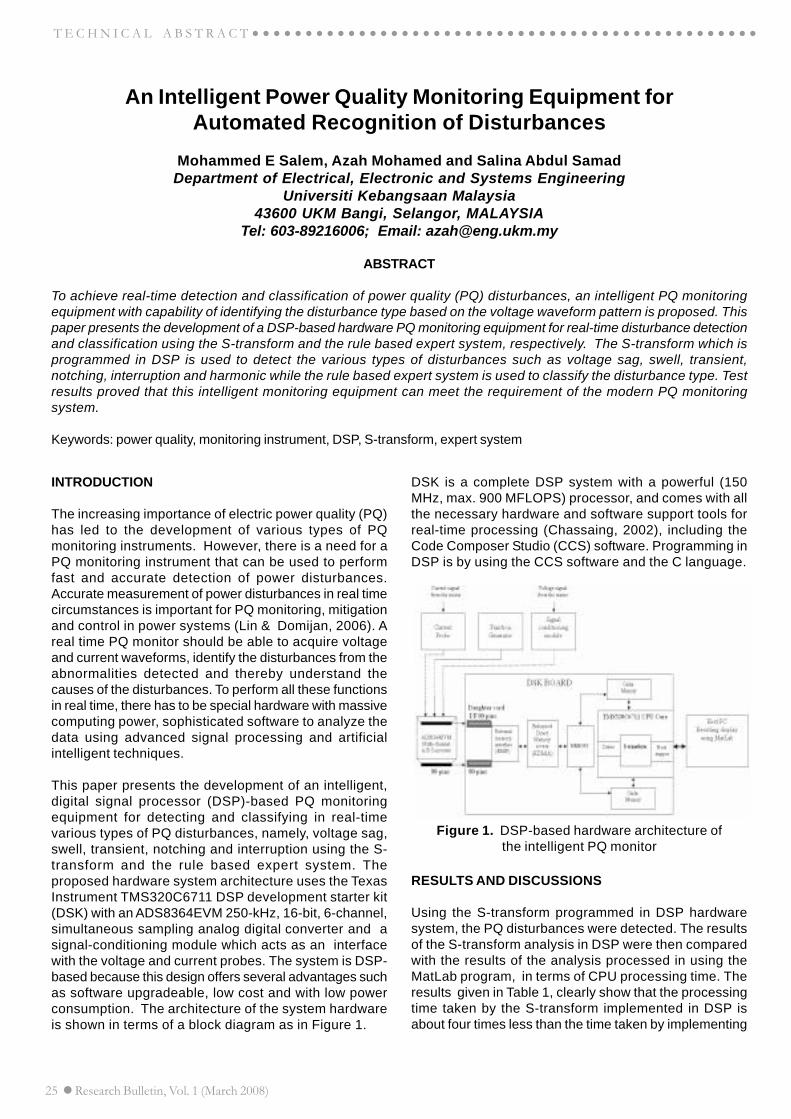
This paper presents the development of an intelligent,digital signal processor (DSP)-based PQ monitoringequipment for detecting and classifying in real-timevarious types of PQ disturbances, namely, voltage sag,swell, transient, notching and interruption using the S-transform and the rule based expert system. Theproposed hardware system architecture uses the TexasInstrument TMS320C6711 DSP development starter kit(DSK) with an ADS8364EVM 250-kHz, 16-bit, 6-channel,simultaneous sampling analog digital converter and asignal-conditioning module which acts as an interfacewith the voltage and current probes. The system is DSP-based because this design offers several advantages suchas software upgradeable, low cost and with low powerconsumption. The architecture of the system hardwareis shown in terms of a block diagram as in Figure 1.
RESULTS AND DISCUSSIONS
Using the S-transform programmed in DSP hardwaresystem, the PQ disturbances were detected. The resultsof the S-transform analysis in DSP were then comparedwith the results of the analysis processed in using theMatLab program, in terms of CPU processing time. Theresults given in Table 1, clearly show that the processingtime taken by the S-transform implemented in DSP isabout four times less than the time taken by implementing
Figure 1. DSP-based hardware architecture ofthe intelligent PQ monitor
DSK is a complete DSP system with a powerful (150MHz, max. 900 MFLOPS) processor, and comes with allthe necessary hardware and software support tools forreal-time processing (Chassaing, 2002), including theCode Composer Studio (CCS) software. Programming inDSP is by using the CCS software and the C language.
Research Bulletin, Vol. 1 (March 2008) 26
T E C H N I C A L A B S T R A C T
Power Quality Disturbance
DSP CPU Execution time (s)
PC CPU Execution time (s)
Clean signal 0.0451 0.2180
Voltage sag 0.0451 0.2030
Voltage swell 0.0458 0.2340
Interruption 0.0451 0.1720
Voltage notching 0.0451 0.2030
Impulsive transient 0.0451 0.2190
CONCLUSION
An intelligent power quality monitor is developed for thepurpose of automated PQ disturbance detection andclassif icat ion. Real-t ime implementat ion of PQdisturbance detection on the DSP hardware using the S-transform proves that accurate and fast detection of PQdisturbances can be achieved.
REFERENCES
[1] Lin T., Domijan A., “Real time Measurement of PowerDisturbances Part 1. Survey and a Novel ComplexFi l ter Approach”, Electr ic Power SystemsResearch, Elsevier, Science Direct, 2006.
[2] Chilukuri M. V., Dash P. K., “Multiresolution S-Transform-Based Fuzzy Recognition System forPower Quality Events”, IEEE Transactions onPower Delivery, 2004.
[3] Chassaing R., “DSP Application Uses C and theTMS320C6X DSK,” New York: Jone Wiley & Sons.Inc, 2002.
Detailed results of this study has been reported in:Mohammed E Salem, Azah Mohamed, Salina AbdulSamad, 2007. Fast detection and Classification of PowerQuality Disturbance Based on DSP Implementation,International Review of Electrical Engineering, Vol.2, N.2,163 – 170.
using MatLab in PC. Hence, the reduction in processingtime allows fast detection of PQ disturbances.
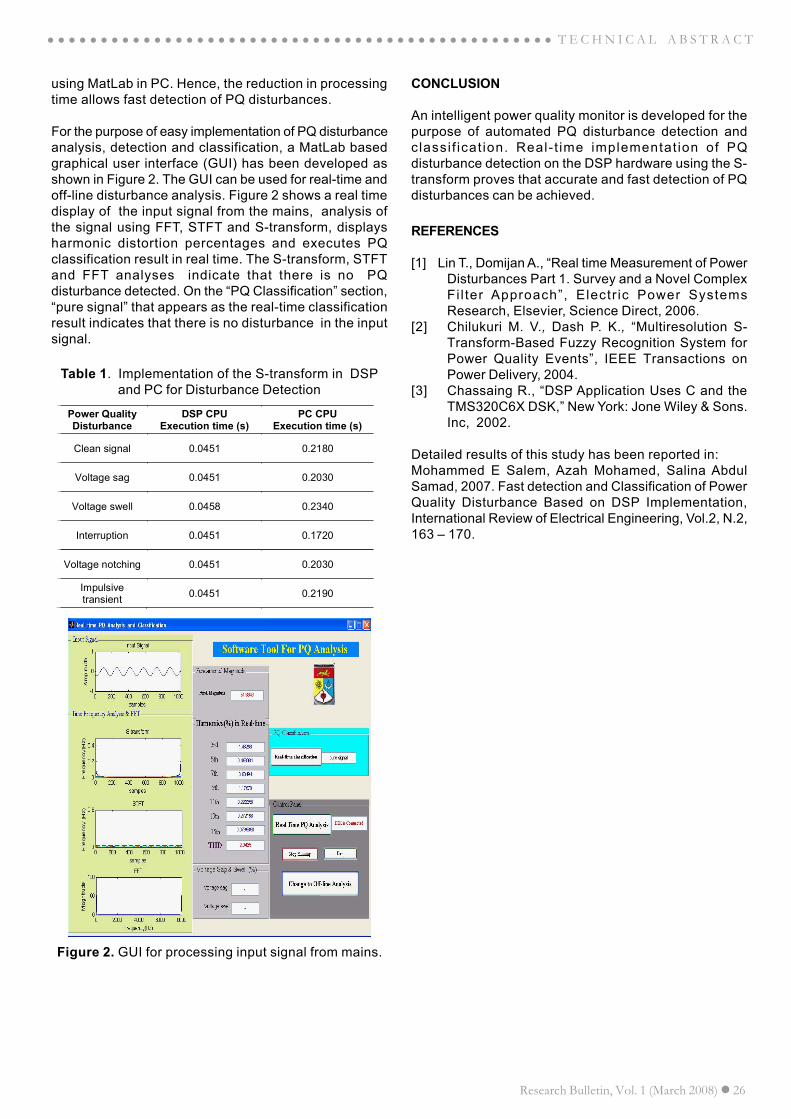
For the purpose of easy implementation of PQ disturbanceanalysis, detection and classification, a MatLab basedgraphical user interface (GUI) has been developed asshown in Figure 2. The GUI can be used for real-time andoff-line disturbance analysis. Figure 2 shows a real timedisplay of the input signal from the mains, analysis ofthe signal using FFT, STFT and S-transform, displaysharmonic distortion percentages and executes PQclassification result in real time. The S-transform, STFTand FFT analyses indicate that there is no PQdisturbance detected. On the “PQ Classification” section,“pure signal” that appears as the real-time classificationresult indicates that there is no disturbance in the inputsignal.
Table 1. Implementation of the S-transform in DSPand PC for Disturbance Detection
Figure 2. GUI for processing input signal from mains.
Research Bulletin, Vol. 1 (March 2008) 28
○ ○ ○ ○ ○ ○ ○ ○ ○ ○ ○ ○ ○ ○ ○ ○ ○ ○ ○ ○ ○ ○ ○ ○ ○ ○ ○ ○ ○ ○ ○ ○ ○ ○ ○ ○ ○ ○ ○ ○ ○ ○ ○ ○ ○ ○ ○ ○ T E C H N I C A L A B S T R A C T
CONCLUSION
This study has shown that the spectrographic featurescan be used successfully in a speaker authenticationsystem using the UMACE filter as the classifier.Experimental results have shown that UMACE filters isa viable technique for biometric authentication and theperformance of the multi-modal system in noisyconditions is shown to be more robust than a purelyspeech-based system.
REFERENCES
Kuncheva L.I., 2002. A Theoretical Study on Six ClassifierFusion Strategies, IEEE Transaction On Pattern Analysisand Machine Intelligence, vol.24(2), 348-353.
Reynolds D.A., 2002. An Overview of Automatic SpeakerRecognition Technology, Proceeding of IEEE onAcoustics, Speech and Signal Processing, 4072-4075.
Teoh A., Samad S.A., Hussain A., 2004. NearestNeighbourhood Classifiers in Bimodal BiometricVerification System Fusion Decision Scheme, Journalof Research and Practice in Information Technology,vol.36(1), 47-62.
Venkataramani K., Vi jaya Kumar B.V.K., 2004.Performance of Composite Correlation Filters, OpticalEngineering, vol.43(8), 1820-1827.
Detailed results of this study have been reported in:
Salina Abdul Samad, Dzati Athiar Ramli, Aini Hussain2007. Person Identification using Lip Motion sequence,Lecture Notes on Computer Science (AI Series) Springer-Verlag, Berlin Heidelberg: 839-846.
Salina Abdul Samad, Dzati Athiar Ramli, Aini Hussain2007. A Multi-Sample Single-Source Model UsingSpectrographic Features for Biometric Authentication.IEEE Int. Conf. on Information, Communications andSignal Processing (ICICS 2007), Singapore. In press.
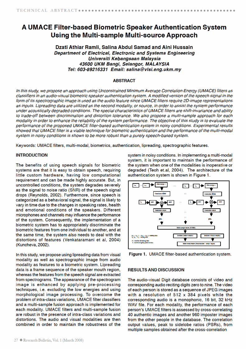
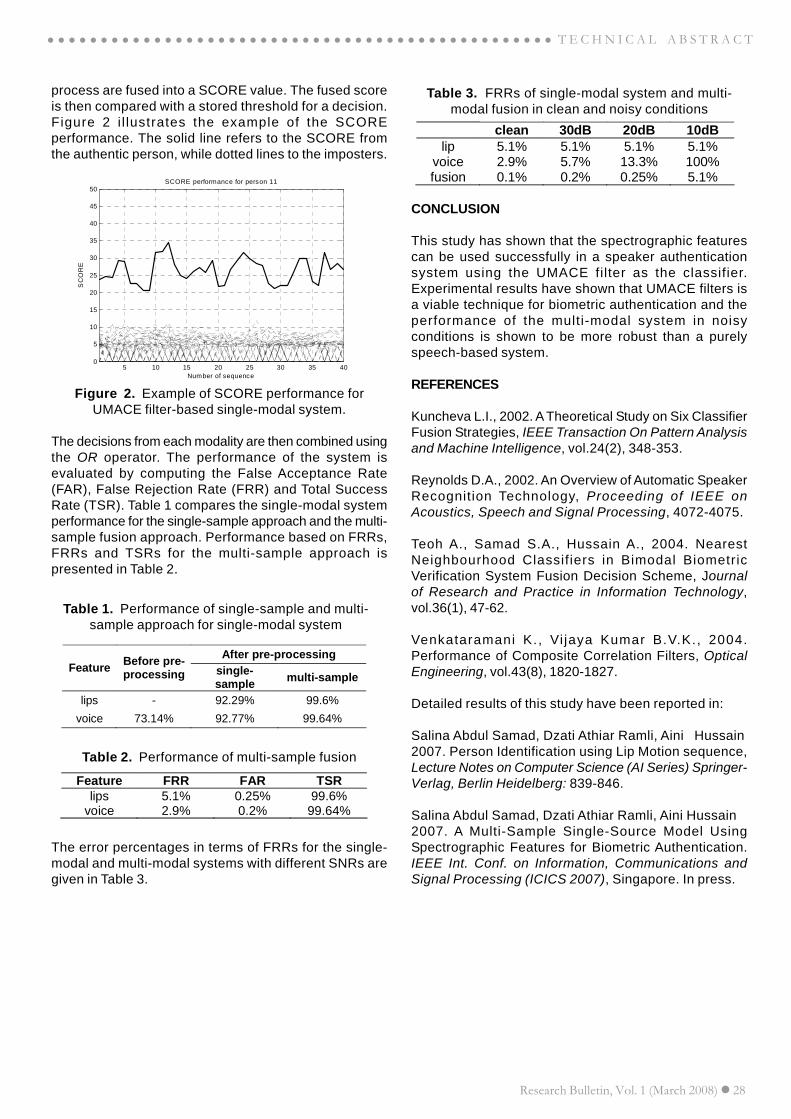
process are fused into a SCORE value. The fused scoreis then compared with a stored threshold for a decision.Figure 2 i l lustrates the example of the SCOREperformance. The solid line refers to the SCORE fromthe authentic person, while dotted lines to the imposters.
The decisions from each modality are then combined usingthe OR operator. The performance of the system isevaluated by computing the False Acceptance Rate(FAR), False Rejection Rate (FRR) and Total SuccessRate (TSR). Table 1 compares the single-modal systemperformance for the single-sample approach and the multi-sample fusion approach. Performance based on FRRs,FRRs and TSRs for the multi-sample approach ispresented in Table 2.
Figure 2. Example of SCORE performance forUMACE filter-based single-modal system.
Table 1. Performance of single-sample and multi-sample approach for single-modal system
Table 2. Performance of multi-sample fusion
The error percentages in terms of FRRs for the single-modal and multi-modal systems with different SNRs aregiven in Table 3.
Table 3. FRRs of single-modal system and multi-modal fusion in clean and noisy conditions
5 10 15 20 25 30 35 400
5
10
15
20
25
30
35
40
45
50SCORE performance for person 11
Number of sequence
SC
OR
E
After pre-processing Feature Before pre-
processing single-sample multi-sample
lips - 92.29% 99.6%
voice 73.14% 92.77% 99.64%
Feature FRR FAR TSR lips 5.1% 0.25% 99.6%
voice 2.9% 0.2% 99.64%
clean 30dB 20dB 10dB lip 5.1% 5.1% 5.1% 5.1%
voice 2.9% 5.7% 13.3% 100% fusion 0.1% 0.2% 0.25% 5.1%
29 Research Bulletin, Vol. 1 (March 2008)
T E C H N I C A L A B S T R A C T
Wavelet Analysis Applied To Seismic Surface Waves For In SituAttenuation Of Layered Soil Medium
Mohd Raihan Taha, Sri Atmaja P. Rosyidi and Zamri ChikDepartment of Civil and Structural Engineering
Universiti Kebangsaan Malaysia43600 UKM Bangi, Selangor, MALAYSIA
Tel: 603-89216212; Fax: 603-89216147Email:[email protected], or [email protected]
ABSTRACT
Noises from nature and other human-made sources disturb generated surface wave and data. The propagation ofsurface waves also has non-stationary pattern where the harmonic solution of transformation is not adequate toanalyse all information for response spectrum. In this research, a continuous wavelet transform (CWT) based onmother wavelet of Gaussian Derivative was used to analyze seismic waves in different frequency and time. Time-frequency wavelet (TFW) spectrum was employed to localize the interest seismic response spectrum of surfacewaves. Research results showed that wavelet analysis is able to determine and identify reliable surface wave spectrumof layered soil. This technique is a valuable method that may be applied to problems related to non-stationaryresponse spectrum of seismic surface wave. A frequency-independent attenuation empirical coefficient was alsoobtained from the wavelet spectrum.
Keywords: wavelet, Gaussian Derivative, surface waves, attenuation, soil medium
INTRODUCTION
Many surface wave studies have been conducted to obtainthe damping and stiffness properties of layered soilmedium. In surface wave methods, the geotechnicalproperties are analyzed from humongous amount of nonstationary seismic data. In previous surface wave method,data analysis in both time and frequency domain hasbeen carried out using fast Fourier transforms for varioussystem responses in different frequency from several inputmotions with time. However, Fourier transform works byexpressing any arbitrary periodic function of time withperiod as sum a set of sinusoidal. Thus some informationof non-stationary seismic data in the analysis maybe lost.The motivation of this research is to provide an advancedanalysis of seismic surface wave data using waveletanalysis to obtain the attenuation properties of layeredsoil medium.
Attenuation in soil dynamics is a phenomenon related tointeraction of several mechanisms that contribute toenergy dissipation of the seismic wave during dynamicexcitation. The decrease in energy density of the verticalcomponent of the surface waves with distance due onlyto geometric configuration is also called as the radiationdamping or geometric spreading which is expressed by:
where á = the attenuation coefficient of the material (1/m) and w1, w2 = the amplitude of seismic response atdistance r1 and r2 from the source, respectively. Theamplitude of seismic response is constructed by
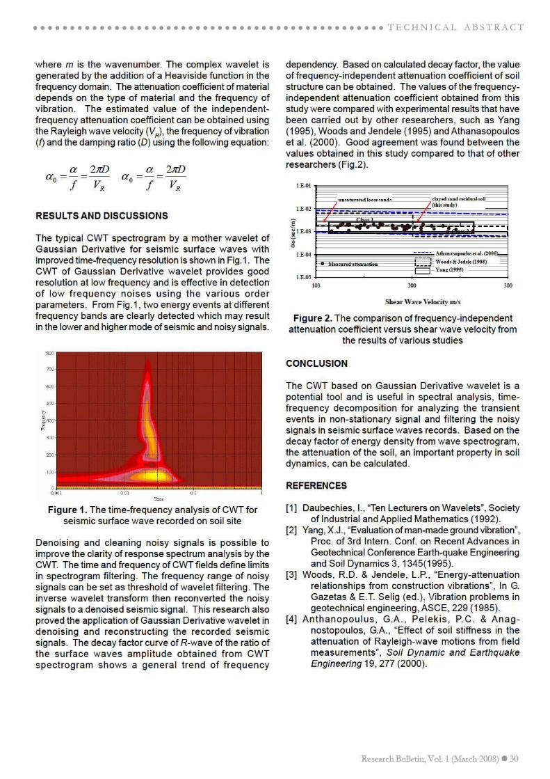
continuous wavelet transform (CWT) based on motherwavelet of Gaussian Derivative. The continuous wavelettransform (CWT) technique is becoming a common toolfor analyzing localized energy density of the seismic signalprocessing particularly in non-stationary problems. The
where is the complex conjugate of ψ, FW(,τ) is thetime-scale map. In order to reconstruct the function f(t)from the wavelet transform, Calderon’s identify(Daubechies 1992) can be used and is obtained as:
In this research, the mother wavelet of the GaussianDerivative was used. The real component of GaussianDerivative wavelet in the time and frequency domains isdefined as follows:
ψ
RVD
fπαα 2
0 == RVD
fπαα 2
0 ==
( ) ( )
στ
σσ
στψτσ
ψ
ddtFC
tf W 2,1
−
= ∫ ∫∞
∞−
∞
∞−
( ) ( ) ( )2
2
21
1 1
0te
dd
mt m
mm−
+Γ
−=
+
ηψ
( ) ( ) ( )
+Γ
−=−
22
21
ˆ 0
ω
ωωψs
esm
is mm
)(
2
112
21 rrn
errww −−
= α
31 Research Bulletin, Vol. 1 (March 2008)
T E C H N I C A L A B S T R A C T
Urban Renewal and Design for Backlanes of CommercialBuildings in City Centres
Ismar M.S.Usman, Abdul Halim Ismail, M. F. Irfan Mohd Nor, Azimin ShamsulMohd Tazilan and Noraziah Mohammad
Department of ArchitectureUniversiti Kebangsaan Malaysia
43600 UKM Bangi, Selangor, MALAYSIATel: 603-89216942/ 6299; Email: [email protected]
ABSTRACT
Urban renewal and design are closely linked to both architecture and planning. The main concerns of urban designare design, structuring and restructuring of public space in urban regions. Backlanes are a neglected area ofplanning and urban design in Malaysia especially in commercial areas in city centers. Based on case studies thathave been done at the Brickfields area and Jalan Haji Taib, Kuala Lumpur, some major issues are identified. Someof the issues raised on backlanes are security, diversity in activity and management, unutilized backlane space,negative space, discontinuity and conflict of functions. This technical report focuses on some of the strengths,weaknesseses, opportunities and constraints of backlanes on establishing guidelines for backlane revitilization.
Keywords: Backlanes, Urban design, Urban theories
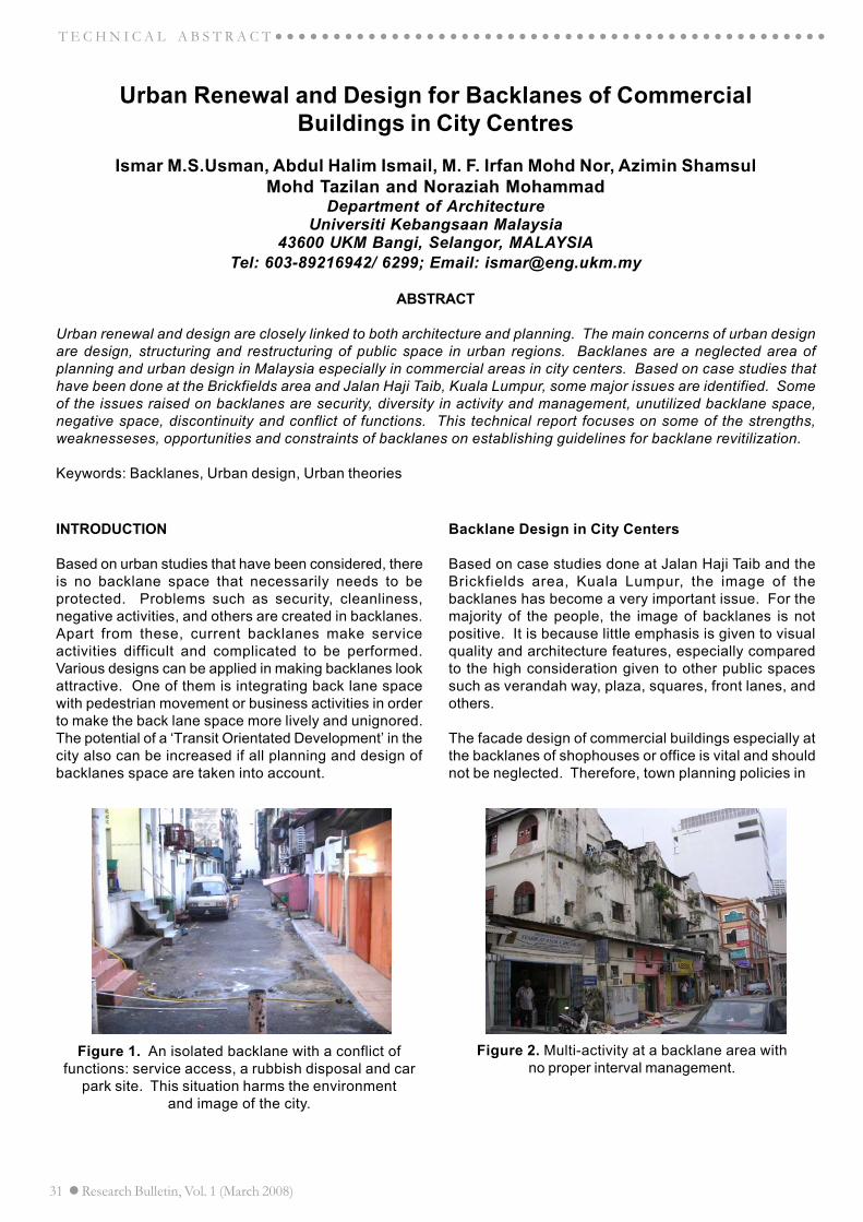
Figure 1. An isolated backlane with a conflict offunctions: service access, a rubbish disposal and car
park site. This situation harms the environmentand image of the city.
Figure 2. Multi-activity at a backlane area withno proper interval management.
INTRODUCTION
Based on urban studies that have been considered, thereis no backlane space that necessarily needs to beprotected. Problems such as security, cleanliness,negative activities, and others are created in backlanes.Apart from these, current backlanes make serviceactivities difficult and complicated to be performed.Various designs can be applied in making backlanes lookattractive. One of them is integrating back lane spacewith pedestrian movement or business activities in orderto make the back lane space more lively and unignored.The potential of a ‘Transit Orientated Development’ in thecity also can be increased if all planning and design ofbacklanes space are taken into account.
Backlane Design in City Centers
Based on case studies done at Jalan Haji Taib and theBrickfields area, Kuala Lumpur, the image of thebacklanes has become a very important issue. For themajority of the people, the image of backlanes is notpositive. It is because little emphasis is given to visualquality and architecture features, especially comparedto the high consideration given to other public spacessuch as verandah way, plaza, squares, front lanes, andothers.
The facade design of commercial buildings especially atthe backlanes of shophouses or office is vital and shouldnot be neglected. Therefore, town planning policies in
Research Bulletin, Vol. 1 (March 2008) 32
T E C H N I C A L A B S T R A C T
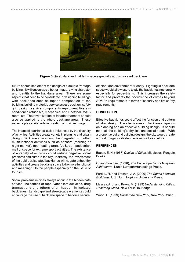
Figure 3 Quiet, dark and hidden space especially at this isolated backlane
future should implement the design of a double frontagebuilding. It will encourage a better image, giving characterand identity to the backlane area. There are someaspects that need to be considered in designing buildingswith backlanes such as façade composition of thebuilding, building material, service access position, safetygrill design, service components equipment like air-conditioner, refuse bin, mechanical and electrical (M&E)room, etc. The revitalization of facade treatment shouldalso be applied to the whole backlane area. Theseaspects play a vital role in creating a positive image.
The image of backlanes is also influenced by the diversityof activities. Activities create variety in planning and urbandesign. Backlane space could be integrated with othermultifunctional activities such as bazaars (morning ornight market), open eating area, Art Street, pedestrianmall or space for extreme sport activities. The existenceof a variety of activities could reduce negative socialproblems and crime in the city. Indirectly, the involvementof the public at isolated backlanes will negate unhealthyactivities and create backlane space to be more functionaland meaningful to the people especially on the issue oftourism.
Social problems in cities always occur in the hidden pathservice. Incidences of rape, vandalism activities, drugtransactions and others often happen in isolatedbacklanes. Landscape and streetscape elements couldencourage the use of backlane space to become secure,
efficient and environment-friendly. Lighting in backlanespace would allow users to ply the backlanes nocturnallyespecially for pedestrians. This increases the safetyfactor and prevents the occurrence of crimes beyondBOMBA requirements in terms of security and fire safetyrequirements.
CONCLUSION
Effective backlanes could affect the function and patternof urban design. The effectiveness of backlanes dependson planning and an effective building design. It shouldmeet all the building’s physical and social needs. Witha proper layout and building design, the city would createa good image for its denizens as well as visitors.
REFERENCES
Bacon, E. N. (1967) Design of Cities, Middlesex: PenguinBooks.
Chan Voon Fee. (1998), The Encyclopedia of MalaysianAchitecture, Kuala Lumpur:Archipelago Press.
Ford, L. R. and Trachte, J. A. (2000) The Space betweenBuildings. U.S: John Hopkins University Press.
Massey, A. J. and Pryke, M. (1999) Understanding Cities,Unsetting Cities. New York: Routledge.
Wood, L. (1999) Borderline New York, New York: Wien.

33 Research Bulletin, Vol. 1 (March 2008)
T E C H N I C A L A B S T R A C T
Extension of Time According To Standard Formof Building Contract
Ar. Noraziah Mohammad, Ar. Ismar M.S Usman, Muhammad Farihan Irfan Mohd Nor,Abdul Halim Ismail and Ir. Mohammed Alias Yusof
Department of ArchitectureUniversiti Kebangsaan Malaysia
43600 UKM Bangi, Selangor, MALAYSIATel:603-89216963; Email:noraziah@ vlsi.eng.ukm.my
ABSTRACT
This paper explain the provision related to the extension of time (EOT) claims as stated in the PAM 1998 and PWD203 standard form of building contracts. This is followed by the relevant event related to extension of time clausesand also the procedures to claim extension of time as stated in the standard form of building contracts.
Keywords: Standard form of building contract, PAM 1998, PWD 203, Extension of time.
INTRODUCTION
Building contracts are by their very nature complex as itcomprise of different trades and professionals. Thedifficulties of completing a project on time due to relevantevents have threatened the smooth running of the project.Therefore most building contracts have made provisionfor extending the contract under the extension of timeclauses of the contract to deal with the relevant eventthat is likely to effect the completion date of the project.
This provision is important for the employer whose abilityto claim liquidated damages if the delay is not due to therelevant event as stated in the contract. As for thecontractor, we benefits by having an extension of timeand lower the risk of an imposition of liquidated damagesunder the provision of contract. Generally in Malaysiathere are two types of standard form of building contractswhich address this subject in one way or the other.
These standard forms of building contracts are (1)Persatuan Akitek Malaysia 1998 standard form of buildingcontract and (2) Public Work Department / PWD 203Standard form of building contract. Figure 1 illustrates
Figure 1. Standard form of building contract
the standard type of building contract in Malaysia.
EXTENSION OF TIME CLAUSES IN BUILDING CON-TRACT
The extensions of time clauses in the standard of buildingcontract are express under the following clauses:
The grounds that allow the architect to grant extensionof time are acknowledged as relevant events. In generalthese relevant events are the same for both standard formcontracts except there is an additional provision providedin the PWD 203A form of contract for delays due todisputes with a neighboring owner and also delays ingiving site possession which does not appear in PAM1998.
The relevant events clauses that entitle the contractorfor claiming of extension of time in the PAM 1998 andPWD condition of contracts are tabulated in the Table 1.
Table 1. Relevant event clauses of the standard form ofbuilding contract
Relevant event for extension of time can be divided intotwo groups:
Standard form of building contract
Government Sector
Private Sector
PWD 203A PAM 98/ PAM NSC 98
PAM 1998 Form PWD Form Clause 23.7 clause 43 Paragraphs (i) to (xii) Paragraph (i) to (xi)
1. Persatuan Akitek Malaysia (PAM) 1998 condition of contract - clause 23.
2. Public Work Department (PWD) 203A condition of contract - clause 43.

Research Bulletin, Vol. 1 (March 2008) 34
○ ○ ○ ○ ○ ○ ○ ○ ○ ○ ○ ○ ○ ○ ○ ○ ○ ○ ○ ○ ○ ○ ○ ○ ○ ○ ○ ○ ○ ○ ○ ○ ○ ○ ○ ○ ○ ○ ○ ○ ○ ○ ○ ○ ○ ○ ○ ○ T E C H N I C A L A B S T R A C T
1. Neutral Event
These are events, which are beyond the employers andcontrol provides the contractor for extension of time andrelieves him from liability of liquidated damages. Theexamples of the neutral events are force majuere, fire,storm and exceptionally inclement weather and also workby statutory undertakers.
2. Employer Delays
This covers a variety of delays caused by an employer,such as failure to give possession and access to site,delay due to the employer or his nominated contractor.Employer’s delays also can rise from variation orders,discrepancies between contract drawing and also theissue of late information, details and also instructionsthat the contractor has requested in writing.
PROCEDURE OF CLAIMING OF EXTENSION OF TIME
Whenever it become reasonably apparent the progressof the work will be delayed beyond the date of completionthe contractor is required to give written notice, which is
known as notice of delays to the architect which mustinclude the following:
a. The material circumstances;b. Any event in the opinion of the contractor is a relevantevent.;c. Details of the expected effect of the relevant eventwhich he anticipates. In the event of the contractor’s failureto submit the application of extension in time and thehanding in of necessary documents required, then thearchitect shall fix a new completion date within areasonable time.
REFERENCES
Standard form of building contract by Persatuan AkitekMalaysia, clause 23.
Standard form of condition of contract (JKR 203A) byPublic Work Department of Malaysia, clause 43.
Sundra Rajoo (2000) the standard form of buildingcontract (PAM 1998) 2nd. Edition.
35 Research Bulletin, Vol. 1 (March 2008)
○ ○ ○ ○ ○ ○ ○ ○ ○ ○ ○ ○ ○ ○ ○ ○ ○ ○ ○ ○ ○ ○ ○ ○ ○ ○ ○ ○ ○ ○ ○ ○ ○ ○ ○ ○ ○ ○ ○ ○ ○ ○ ○ ○ ○ ○ ○ ○T E C H N I C A L A B S T R A C T
The Development of a Sustainably Responsive Ultra Low EnergyTerrace Housing Architecture for the Tropics Incorporating the
Raised Floor Innovation
Mazlan Mohd Tahir, Nur Akmal Goh Abdullah, Mastor Surat, Zabidi Hamzah,Zuhairuse Md Darus, Ismar M.S. Usman, Noraziah Mohamad
Department of Architecture, Faculty of EngineeringUniversiti Kebangsaan Malaysia
43600 UKM Bangi, Selangor, MALAYSIATel:603-89216680; Email:[email protected]
ABSTRACT
The ubiquitous terrace house is undeniably the most popular and affordable housing type in Malaysia. It has longbeen considered as one of the densest forms of property development and has become the common typology ofaccommodating the masses for this country. However, its design has been plague with various issues for decades.We are currently living separate and individual lives in the sea of congested modern housing and we will be foreverplagued by the mercy of crime, climate, cultural tensions and threats from accidents. Terrace housing has beenassociated among others with poor design, thermal comfort problems, safety issues, unsightly renovations, socialdisunity and cultural misgiving. In contrary to the sustainable tropical architecture with sun shading devices, ventilation,openings and the use of local material such as timber, terrace houses have been designed as masonry and reinforcedconcrete boxes fitted with air conditioner. The modern day terrace house has perhaps overlooked one of the mostimportant elements of a tropical house that is the raised floor. The traditional raised floor design incorporates manyissues such as ventilation, lighting, thermal comfort, safety and security as well as social considerations. Therefore,this research intends to explore the sustainable aspects of our traditional architecture in creating a uniquely newdesign for in-house habitation as well as providing for an aesthetically pleasing look. It suggests a possible andpromising way of increasing the livability of terrace housing with a sustainable approach and with the incorporation ofthe raised floor innovation.
Keywords: raised floor, ventilation, lighting, thermal comfort, social aspects.
INTRODUCTION
The terrace house’s posit ion as the undisputedaccommodation for the masses is likely to persist givenits priority in the current Ninth Malaysia’s Plan. Approvalof such houses is also among the highest of all propertytypes and demand is expected to increase. However, littlehas changed in terms of its design innovation for the last25 years. New designs are devoid of design principlesand are usually aesthetically offensive. Buildings are builtfast with minimum professional effort. The livability indexfor terrace housing in Malaysia, with respect, has neverbeen analysed. Uninteresting design, inflexibility of space,inappropriate renovations, poor ventilation, lighting andthermal comfort resulted in unacceptable housing livingculture in urban and sub urban community area inMalaysia. Most housing schemes were planned in gridironlayout for maximum land use. Hence, it has resulted inunits designed with no sensitivity to warm humid tropicalclimate’s requirements as those evident in the traditionalMalay houses. Terrace housing community is seen aslacking the architectural qualities and social integrity asseen in the kampung.
DISCUSSIONS
The design development will look at various possiblesystem and configuration as well as architecturalconcepts which incorporate sustainable approaches suchas determined below.:
1. Introduction of the Raised Floor (Building on Stilts)as a new form of sustainable architecture.The architecture on stilts has only been seen ontraditional buildings but rarely implemented oncontemporary buildings.
2. Green roof (Utilizing the green concrete technologycreated at the Faculty) and solar panels.This strategy would reduce direct heat radiation fromthe sun to the roof as well as provide adequateaddit ional social space and location for theinstallation of BIPV panels.
3. Rain water harvesting to capture the potential supplyfrom the tropical rain.
4. Industrialized Building System (IBS) with modularpanels and modular coordination.This is in lieu of our Governments call for the use of
Research Bulletin, Vol. 1 (March 2008) 36
○ ○ ○ ○ ○ ○ ○ ○ ○ ○ ○ ○ ○ ○ ○ ○ ○ ○ ○ ○ ○ ○ ○ ○ ○ ○ ○ ○ ○ ○ ○ ○ ○ ○ ○ ○ ○ ○ ○ ○ ○ ○ ○ ○ ○ ○ ○ ○ T E C H N I C A L A B S T R A C T
IBS to improve the quality of buildings.5. Sustainable Material Design application (which would
be incorporated into the modular panels).6. Shading devices (fixed as well as adjustable).7. Internal courtyard design.8. Energy performance and life-cycle analysis.
THE MISSING ELEMENT - THE RAISED FLOOR OF THETRADITIONAL MALAY HOUSE
The essence of modernism and its subsequent philosophi-cal and aesthetic development have often not been un-derstood by many architects in Asian countries. At thesame time, a respect for tradition and our own architec-tural heritage is widely acceptable. They provide the ba-sic foundations toward developing an exciting contem-porary reinterpretation of the vernacular. The manifesta-tion of the traditional Malay house can easily be identi-fied by the three basic elements of architectural studies.They are the elements of floor, wall and roof. The tradi-tional Malay house clearly shows a distinctive separa-tion as evident its zoning of the elements. Many a re-search has been done to dissect and look at various com-ponents and elements of the traditional Malay house butthe raised element has not been considered at greatlength.
The raised floor of the traditional Malay house has oftenpresented itself with many possibilities. In an environ-ment which is characterized by heavy, tropical rain ac-companied by the now frequently heavy flash flood, theraised floor tradition is perhaps the most ideal and im-mediate solution to the problem. This is a vital designelement, which has been overlooked for years and whichdesign could possibly bear a significant impact on ourhousing system. It is the reflection of the society’s ac-cumulated wisdom and collective images. The traditionalraised floor not only allows for easy passage of air intoand through the house but the area beneath the house isalso comfortable for children to play and venue for vari-ous daily activities
ADVANTAGES OF THE RAISED FLOOR IN A HOT ANDHUMID CLIMATE OF MALAYSIA
• The raised floor increases air movement in and out ofbuilding.
• Increasing the floor level from ground may requireadditional cost but the cost could in the long run bejustifiable considering the addition space achievedand the possible functions.
• Effective counter measures from animals and insectsas well as comfort from the constant havoc of flashfloods.
• More privacy with additional consideration to detailedwall design. Floor rose at a level of more than that ofa normal human height automatically restrict viewsfrom pedestrians.
• Better security and fewer requirements of specificfacilities normally associated with most terrace hous-ing schemes.
• Better views and option for integration of landscapedesign.
THE MODERN CONCEPT OF RAISED FLOOR HOUS-ING
The floor system of the traditional Malay house has oftenpresented itself with a multifaceted usability, be it tech-nically, environmentally or socially. Its characteristics canbe considered when designing with the modern conceptof raised floor.
The raised floor can be designed to allow for:• Ventilation (good air flow movement)• Lighting (good light filtering in from the floor)• Thermal Comfort (retardant from direct heat from the
ground)• Privacy (visual and social)• Functionality (multifunction of usage)• Economy (low energy usage, cost effective)
Advantages of the new design
As with the raised floor of the traditional house, the newraised floor design presents us with several possibilities:• Better ventilation (houses are cooler)• Natural lighting quality (a more radiant house)• Saves energy (less lighting needed)• Adjustable mechanism for improved thermal com-
fort, ventilation and lighting• Ample community space
The question that truly begs at this juncture is can theraised floor design increase livability as well as providingfunctionality and aesthetics to the modern Malaysianhome. An innovative design is hereby proposed.
It is also fair to reason out that the comparison madebetween the traditional Malay house and the modern ter-race house is in the architectural elements or better yetthe missing element. The traditional Malay house is se-lected, compared to perhaps traditional Chinese housesor the Sarawak longhouse, as it is the most prevalenttraditional architecture in the country.
CONCLUSION
Sometime it takes Mother Nature to indicate to us whatwe have opt to neglect. The ‘raised floor design” incorpo-rates exciting features that addresses issues such asthermal comfort, ventilation, lighting, aesthetics, com-fort and social. Furthermore, this design can be immedi-ately used in Malaysian housing due to its adherence tostandard measurements.
Research in this area could provide a better designsolution, flexibility for a current and new scenario ofterrace housing or for what matters even more, anybuilding design in Malaysia, which satisfies both privateand public spaces. The design scheme will enhance localand existing culture, integrates into public facilities andactivities and can be stretched into a new community

37 Research Bulletin, Vol. 1 (March 2008)
○ ○ ○ ○ ○ ○ ○ ○ ○ ○ ○ ○ ○ ○ ○ ○ ○ ○ ○ ○ ○ ○ ○ ○ ○ ○ ○ ○ ○ ○ ○ ○ ○ ○ ○ ○ ○ ○ ○ ○ ○ ○ ○ ○ ○ ○ ○ ○T E C H N I C A L A B S T R A C T
lifestyle. This can be tested on in new residential areas,urban as well as suburban areas. The design couldincorporate low energy design in order to build asustainable mass housing architecture.
REFERENCES
1. Aziz Deraman. (2000). Tamadun Melayu danPembinaan Bangsa Melayu, Dewan Bahasa danPustaka, Kuala Lumpur.
2. Gibbs, Philip. (1987). Building a Malay House, OxfordUniversity Press.
3. Kamaruddin Md.Ali. (1983). A Vanishing Heritage:The Old Traditional Malay House,
4. Thesis Master, University of York.
5. Mohamad Tajuddin Mohd Rasdi & Ghofar RozaqNazila. (2003). Housing Crisis in Malaysia: Back toa Humanistic Agenda, Pusat Kajian Alam Bina DuniaMelayu, Faculty of Built Environment, UniversitiTeknologi Malaysia.
6. Mohamad Tajuddin Mohd Rasdi, et. al. (2005).Housing The Architectural Heritage of the MalayWorld: The Traditional Houses, Universiti TeknologiMalaysia.
7. Yuan, Lim Jee. (1981). The Malay House:Rediscovering Malaysia’s Indigenous Shelter System,Institut Masyarakat.
8. Zulkifli Hanafi. (1999). Rekabentuk Bangunan dalamIklim Panas dan Lembap di Malaysia, Dewan Bahasadan Pustaka.

Research Bulletin, Vol. 1 (March 2008) 38
○ ○ ○ ○ ○ ○ ○ ○ ○ ○ ○ ○ ○ ○ ○ ○ ○ ○ ○ ○ ○ ○ ○ ○ ○ ○ ○ ○ ○ ○ ○ ○ ○ ○ ○ ○ ○ ○ ○ ○ ○ ○ ○ ○ ○ ○ ○ ○ T E C H N I C A L A B S T R A C T
How Representation of Surface Constructibility Affects CAD Usage in Architecturel Practices
Muhammad Farihan Irfan Mohd Nor, Ismar Minang Satotoy,Abdul Halim Ismail, Noraziah Mohamad
Architecture DepartmentFaculty of Engineering, Universiti Kebangsaan Malaysia
43600 UKM Bangi, Selangor, Malaysia.Tel: 603 8921 6844/6299 Fax: 603 8921 6841
E-mail: [email protected]
INTRODUCTION
The application of computer aided design has in variousways affected the architect’s practice. Some practiceslook at it as just a sophisticated draughting tool thatenables them to attain better effectiveness; others see itfacilitating communication with the client while a verysmall portion uses it just for reading drawings receivedfrom other participating consultants. Currently some firmshave even started to recognize CAD’s flexibility and easeof use as a tool that provides bigger opportunities end-users in the design of their buildings. Although all threeaspects mentioned above are important, this paper limitsits discussion to the most important aspect, that isdesign.
DESIGN
15 years ago CAD was, in the main, used for 2dimensional drawings. Now there are hundreds of CADapplications that have different functions and capabilities.Although most CAD applications have the same mainobjective, which is to create a group of lines and curvesthat makes up what we all call as drawings, theseapplications have different niches that stretches fromemphasizing daily routines of 2D drawing drafting todrawing management and networking medium betweenclient and designer.
One of the most, if not the most, important aspect thatCAD applications differ greatly from one another is thetype of design that is best used in creating the necessarydrawings. The decisive factor is the type of surface form
that the design is made of. Thus, it is important for us toidentify the types of surface forms that make up most oftoday’s contemporary architecture, from the simplestbuilding form to the more complex such as theGuggenheim Museum in Bilbao, Spain.
A building can be made up of three (3) different types ofsurfaces, namely:-
1. Planar Surfaces
The first form is the simplest of all and is the type thatmost buildings around the world adopt. However, thisform, which is cal led ‘Planar Surfaces’ for i tscharacteristics of flat, straight and very limited Euclideangeometries have very high geometric constraints (Figure1).
Planar forms, which to have been used for centuries,have a construction system that is relatively simpleto understand. There are many construction systemsthat are based on the planar form. This type of form hasbeen accepted, principally because planar constructionsystems are the most logical and simple, making themeasy to understand.
The mathematical descriptions for planar surfaces, whichare Euclidean geometries, are very simple and precisethus making it the simplest form that can be generatedin CAD modelling applications, be it a high-end applica-tion like CATIA or a more traditional and less expensiveapplication like the much earlier versions of AutoCAD orForm Z. The limits of planar forms, that respect the
ABSTRACT
Computer-Aided Design has brought new opportunities that are remarkable and far-reaching in terms of innovationthan any other architectural tool. The productive and evolutive capabilities of this new tool are incomparably greaterthan those offered by previous ones. The computer contributes to the increasing performance of architectural tools,which is fascinating, albeit controversial. The many types of CAD applications offered on the market nowadays mayhave the same ultimate goal, which is to create 3D models. However, these applications have different ways andabilities in carrying this duty; some are capable of producing the most complex of curve surfaces with maximumprecision while others settle down to simpler planar surfaces of a 3D model. These, however, has great implicationson the costing of the application, which is a great matter in running an architectural or design firm.
Keywords: CAD application, surface, 3D modeling, cost
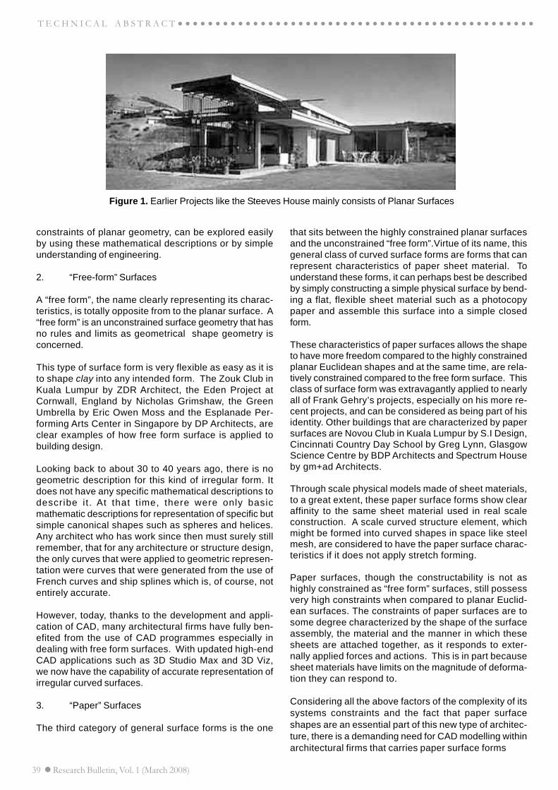
39 Research Bulletin, Vol. 1 (March 2008)
○ ○ ○ ○ ○ ○ ○ ○ ○ ○ ○ ○ ○ ○ ○ ○ ○ ○ ○ ○ ○ ○ ○ ○ ○ ○ ○ ○ ○ ○ ○ ○ ○ ○ ○ ○ ○ ○ ○ ○ ○ ○ ○ ○ ○ ○ ○ ○T E C H N I C A L A B S T R A C T
Figure 1. Earlier Projects like the Steeves House mainly consists of Planar Surfaces
constraints of planar geometry, can be explored easilyby using these mathematical descriptions or by simpleunderstanding of engineering.
2. “Free-form” Surfaces
A “free form”, the name clearly representing its charac-teristics, is totally opposite from to the planar surface. A“free form” is an unconstrained surface geometry that hasno rules and limits as geometrical shape geometry isconcerned.
This type of surface form is very flexible as easy as it isto shape clay into any intended form. The Zouk Club inKuala Lumpur by ZDR Architect, the Eden Project atCornwall, England by Nicholas Grimshaw, the GreenUmbrella by Eric Owen Moss and the Esplanade Per-forming Arts Center in Singapore by DP Architects, areclear examples of how free form surface is applied tobuilding design.
Looking back to about 30 to 40 years ago, there is nogeometric description for this kind of irregular form. Itdoes not have any specific mathematical descriptions todescribe it . At that t ime, there were only basicmathematic descriptions for representation of specific butsimple canonical shapes such as spheres and helices.Any architect who has work since then must surely stillremember, that for any architecture or structure design,the only curves that were applied to geometric represen-tation were curves that were generated from the use ofFrench curves and ship splines which is, of course, notentirely accurate.
However, today, thanks to the development and appli-cation of CAD, many architectural firms have fully ben-efited from the use of CAD programmes especially indealing with free form surfaces. With updated high-endCAD applications such as 3D Studio Max and 3D Viz,we now have the capability of accurate representation ofirregular curved surfaces.
3. “Paper” Surfaces
The third category of general surface forms is the one
that sits between the highly constrained planar surfacesand the unconstrained “free form”.Virtue of its name, thisgeneral class of curved surface forms are forms that canrepresent characteristics of paper sheet material. Tounderstand these forms, it can perhaps best be describedby simply constructing a simple physical surface by bend-ing a flat, flexible sheet material such as a photocopypaper and assemble this surface into a simple closedform.
These characteristics of paper surfaces allows the shapeto have more freedom compared to the highly constrainedplanar Euclidean shapes and at the same time, are rela-tively constrained compared to the free form surface. Thisclass of surface form was extravagantly applied to nearlyall of Frank Gehry’s projects, especially on his more re-cent projects, and can be considered as being part of hisidentity. Other buildings that are characterized by papersurfaces are Novou Club in Kuala Lumpur by S.I Design,Cincinnati Country Day School by Greg Lynn, GlasgowScience Centre by BDP Architects and Spectrum Houseby gm+ad Architects.
Through scale physical models made of sheet materials,to a great extent, these paper surface forms show clearaffinity to the same sheet material used in real scaleconstruction. A scale curved structure element, whichmight be formed into curved shapes in space like steelmesh, are considered to have the paper surface charac-teristics if it does not apply stretch forming.
Paper surfaces, though the constructability is not ashighly constrained as “free form” surfaces, still possessvery high constraints when compared to planar Euclid-ean surfaces. The constraints of paper surfaces are tosome degree characterized by the shape of the surfaceassembly, the material and the manner in which thesesheets are attached together, as it responds to exter-nally applied forces and actions. This is in part becausesheet materials have limits on the magnitude of deforma-tion they can respond to.
Considering all the above factors of the complexity of itssystems constraints and the fact that paper surfaceshapes are an essential part of this new type of architec-ture, there is a demanding need for CAD modelling withinarchitectural firms that carries paper surface forms

Research Bulletin, Vol. 1 (March 2008) 40
○ ○ ○ ○ ○ ○ ○ ○ ○ ○ ○ ○ ○ ○ ○ ○ ○ ○ ○ ○ ○ ○ ○ ○ ○ ○ ○ ○ ○ ○ ○ ○ ○ ○ ○ ○ ○ ○ ○ ○ ○ ○ ○ ○ ○ ○ ○ ○ T E C H N I C A L A B S T R A C T
as their architectural identity. This is because the flex-ibility and intuitiveness of the real physical surface ma-terial does not present a clear affinity with the geometriccontrols and operations of a digitally constructed papersurface. For this, the process to generate geometry intodigital form from a physical paper surface model has tobe done carefully, with very high precision, adding infor-mation and rectification processes, needing many CADexperts and becoming very time consuming.
Still, it is through the extensive use of CAD that papersheet surfaces can be well described and explained inproject documentation thus allowing it to be fully real-ized. CAD applications that are popular for this type ofsurface are CATIA and RevWorks.
CONCLUSION
It is very important to identify the type of surface that areto be applied to designs. A small architectural practicethat only designs and supervises small scale projectssuch as small to medium scale housing development,where planar surfaces, are useful best would use lowerrange CAD appl icat ions such as AutoCAD LT,DesignCAD, Broderbund 3D Home or Sketchup. Thesesoftware not cost much and are good enough to carryout drafting of 2D drawings. However, an architecturalpractice whose job includes designing higher costing ofirregular free forms or paper surface buildings, mightconsider using a high-end CAD application such as CATIAor Solid Edge.

Research Bulletin, Vol. 1 (March 2008) 41
○ ○ ○ ○ ○ ○ ○ ○ ○ ○ ○ ○ ○ ○ ○ ○ ○ ○ ○ ○ ○ ○ ○ ○ ○ ○ ○ ○ ○ ○ ○ ○ ○ ○ ○ ○ ○ ○ ○ ○ ○ ○ ○ ○ ○ ABSTRACT o f P h D T H E S I S 2007
Analysis and Prediction of The Ionospheric Disturbances DuringSolar Eclipse and Geomagnetic Eclipse and Geomagnetics Storms
Over The Polar Regions
byMohd Awad Hussien Almomani
Doctor of Philosophy in Electrical, Electronic & Systems Engineering (Ph.D.)
Significant interaction between solar wind and earth’s ionosphere takes place at high latitude regions. The ionospherein this region is strongly influenced by precipitating particles and large-scale electric field of magnetospheric origin.Therefore, a number of phenomena such as Large-Scale Traveling Ionospheric Disturbances (LSTIDs), radioscintillations, magnificent aurora and heating of the polar upper atmosphere can be generated. The spatial andtemporal variations of the irregularities in this region are much greater than at lower latitudes. Most of the previousstudies on ionospheric disturbances are highly concentrated at middle and low latitudes of northern hemisphere butpoorly investigated at high latitudes especially in Antarctica due to hostile environment and high maintenance cost.Due to the scarcity of measurements over Antarctica, several ionospheric phenomena such as the physical processesduring solar eclipses, interhemispheric conjugacy effects and storm dynamics are still not completely understood.The advent of Global Positioning System (GPS) provides a low cost solution for monitoring the ionosphere on theglobal basis. Currently, the worldwide GPS grid-based technique is used for monitoring the global response of ionosphericstorms. The method, although practical, is based on the measurements of surface intensity, therefore lacks detailinformation on storm vector. Based on these arguments, this thesis aims at achieving the following: 1) to analyze andpredict the relationship between solar eclipse magnitude and Total Electron Content (TEC) depletion and examine thegeomagnetic field disturbances during the solar eclipse of 23rd November 2003, 2) to study the impact of StormEnhanced Density (SED) on GPS scintillation at nearly conjugate points, 3) to develop a novel method to determinestorm vector using single GPS station data, and 4) to investigate the velocity and direction of LSTIDs during SEDperiods. Statistical analysis for the ratio between GPS TEC depletion during solar eclipse at Scott Base (SBA),McMurdo (MCM4), Casey (CAS1), Davis (DAV1) and Syowa (SYOG) stations and the magnitude of solar eclipseshowed nearly linear relationship occurred between eclipse magnitude and amplitude of TEC depletion. The geomagneticfield disturbances during solar eclipse are examined by analyzing the magnetometer readings at SBA, CAS1 andDAV1 stations. The measurements showed pronounced decrease occurred in the north-south component (Bx), whileno effect on east-west (By) and down-up (Bz) components. The study of SED impact on GPS scintillation at nearlyconjugate points during severe storms during 2003-2004 showed pronounced scintillation occurrence at the nightsidehemisphere (2-3 times higher than dayside hemisphere). Results also showed that periods of pronounced scintillationare corresponding to the presence of SED events. The novel method employs temporal and spatial variations of rateof change of TEC (ROT) and TEC measurements from individual GPS satellites above single station to determine thestorm vector. In the novel method, the time delay and location difference of almost similar TEC gradients shapesobserved by different satellites above a particular station suggest a movement of plasma in a particular direction andvelocity. The outcomes of the method showed that during SED period, the ionospheric plasma above SBA stationexhibits a rotation response with a velocity range between 100-300 m/s. Investigations of the velocity and direction ofthe LSTIDs during the SED events over Antarctica were carried out based on temporal and spatial variations of theTEC measurements at SBA, MCM4, CAS1 and DAV1 stations. Analyses showed that during storm periods theLSTIDs propagate equatorward or poleward with a velocity magnitude greater than 600 m/s.
For further correspondence kindly contact:
Professor Dr. Mohd Alauddin Mohd Ali (Main Supervisor)Department of Electrical, Electronic & Systems EngineeringUniversiti Kebangsaan Malaysia43600 UKM Bangi, Selangor, MALAYSIATel: 603-89216302; Fax: 603-89216146; Email: [email protected]
42 Research Bulletin, Vol. 1 (March 2008)
○ ○ ○ ○ ○ ○ ○ ○ ○ ○ ○ ○ ○ ○ ○ ○ ○ ○ ○ ○ ○ ○ ○ ○ ○ ○ ○ ○ ○ ○ ○ ○ ○ ○ ○ ○ ○ ○ ○ ○ ○ ○ ○ ○ ○ ○ABSTRACT of P h D T H E S I S 2007
Real-Time Control of Hydraulic Actuator Using RobustZero Phase Error Digital Tracking Control
byRamli Adnan
Doctor of Philosophy in Electrical, Electronic & Systems Engineering (Ph.D.)
Modern mechanical systems such as machine tools, microelectronics manufacturing equipment, mechanical ma-nipulators, and laser cutting and welding system, have become an expanding field in industrial applications and mustbe supported by motion control. Precision and accuracy requirements become more and more stringent because offactors like reduction of components size in modern mechanical devices or microelectronics product and high-qualitysurface-finishing requirements This situation has caused demands for advanced control strategies especially in high-precision, high-speed and robust tracking control. Numerous research in application of digital tracking control usingzero phase error tracking controller (ZPETC) on electrical actuators had been done except on hydraulic actuators.Generally, hydraulic actuators have been widely used in industrial application due to its high force to mass ratio andfast response. The nonlinear natures of hydraulic cylinders have challenged researchers in designing suitable control-ler for motion or tracking control aiming for significantly improve motion or tracking performance. Based on thesescenario and problems, the objective of this research is to develop a new tracking control algorithm based on theavailable control strategies of trajectory ZPETC, trajectory-adaptive ZPETC, and trajectory-adaptive ZPETC with look-ahead learning and carry out analysis through simulation and real-time studies on hydraulic actuator of industrialstandard. The aim of this research is to investigate the effectiveness of the developed control strategy in term oftracking performance. The method without factorization of zeros polynomial with the parameters of gain compensa-tion filter approximated from the recursive least square parameter estimation method was used. This research usesthe models of minimum phase system and non-minimum phase system. However, this research focused on themodel of non-minimum phase system as this system has unstable zero and difficult to control. The models used wereobtained from the experiments conducted from the real hydraulic actuator with different sampling times. The effectson changing the gain compensation filter order to tracking performance of the proposed control strategy will beobserved and the optimum order will be suggested. In this study, trajectory-adaptive ZPETC algorithm has beensuccessfully developed, analyzed, and tested. Simulation and real-time results verified the tracking performanceindicated by the theoretical analysis. Both results show that the proposed algorithm performed better than the exist-ing algorithm in terms of robustness due to the presence of non-minimum phase zero and changes in the nature oftrajectory signal.
For further correspondence kindly contact:
Professor Dr. Mohd Marzuki Mustafa (Main Supervisor)Department of Electrical, Electronic & Systems EngineeringUniversiti Kebangsaan Malaysia43600 UKM Bangi, Selangor, MALAYSIATel: 603-89216100; Fax: 603-89216146; Email: [email protected]

Research Bulletin, Vol. 1 (March 2008) 43
○ ○ ○ ○ ○ ○ ○ ○ ○ ○ ○ ○ ○ ○ ○ ○ ○ ○ ○ ○ ○ ○ ○ ○ ○ ○ ○ ○ ○ ○ ○ ○ ○ ○ ○ ○ ○ ○ ○ ○ ○ ○ ○ ○ ○ ABSTRACT o f P h D T H E S I S 2007
Prototype Development of an Integrated Intelligent SafetySystem for Vehicle Application
byM A Hannan
Doctor of Philosophy in Electrical, Electronic & Systems Engineering (Ph.D.)
In recent years, vehicle occupant safety, security and comfort have become an important research subject in theautomotive industry. Various efforts are being made by the manufacturers to address these issues including thedevelopment of integrated vehicle safety system in view of reducing injuries, loss of life and effects to the environment.The development of such a system are costing manufacturers billions of dollars per year and they are faced withtechnological challenges due to the vast variety and complexity of the individual features in the system that incorporatesvarious technologies such as sensor technology, intelligent system, etc. This thesis affords the prototype developmentof an intelligent safety system for vehicles which involves the integration of an airbag deployment decision system(ADDS) and tire pressure monitoring system (TPMS). The development work can be divided into two main parts: first,system modelling and simulation for the intelligent ADDS, and second, prototype implementation and its integrationwith the TPMS. In system modelling and simulation part, several algorithms and subsystems such as the occupantdetection, classification and positioning subsystem, vehicle crash detection subsystem and its severity analysiswere modelled and simulated. As for the prototype implementation part, the related theoretical framework is firstlydealt with and then followed by the development of the embedded interconnection between hardware objects. Thehardware objects of the intelligent safety system include devices such as TPM module and its receiver module, loadcell, Logitech web-camera, Cross-bow accelerometer, crash generating device, data acquisition card, CPU card,touch screen and ATX switch mode power supply which are interconnected via a C program interface in Lab Window/CVI. TPMS monitors tire pressure and temperature of the four tyres and periodically transmits the data to the prototypeintegrated safety device. TPMS data are also analyzed using principle component analysis and statistical method fortire condition classification. The ADDS prototype implementation involves integration of several subsystems and thekey step is the development of the intelligent decision fusion algorithm implemented through logic combination thatfuses the decisions from the image processing module, weight sensing module of the occupant classification subsystemand the crash detection decision subsystem module. Results obtained from system modelling and simulation verifiedthat the developed ADDS model correctly modelled the actual system. Finally, ADDS and TPMS are integrated via anembedded platform to produce a prototype. The developed integrated system prototype performance is evaluated andvalidated through several test runs. Based on the test results, it can be concluded that this work has successfullydeveloped a prototype of an intelligent safety system for vehicle occupant safety that has been proven unique, robustand intelligent.
For further correspondence kindly contact:
Professor Dr. Aini Hussain (Main Supervisor)Department of Electrical, Electronic & Systems EngineeringUniversiti Kebangsaan Malaysia43600 UKM Bangi, Selangor, MALAYSIATel: 603-89216329; Fax: 603-89216146; Email: [email protected]

44 Research Bulletin, Vol. 1 (March 2008)
○ ○ ○ ○ ○ ○ ○ ○ ○ ○ ○ ○ ○ ○ ○ ○ ○ ○ ○ ○ ○ ○ ○ ○ ○ ○ ○ ○ ○ ○ ○ ○ ○ ○ ○ ○ ○ ○ ○ ○ ○ ○ ○ ○ ○ ○ABSTRACT of P h D T H E S I S 2007
Optical Cross Add and Drop Multiplexer
byMohd Syuhaimi Bin Abd. Rahman
Doctor of Philosophy in Electrical, Electronic & Systems Engineering (Ph.D.)
Optical cross add and drop multiplexer (OXADM) is a newly invented device in optical networks. It is designed with acombined concept of optical cross connect (OXC) and optical add and drop multiplexer (OADM) which is used toincreased efficiency and flexibility of optical network particularly in metropolitan ring and mesh network. OXADM hasalso widened its application to fiber to the home (FTTH) and network security system. The main function of OXADMis to reconfigure the optical channel path while implementing add and drop function simultaneously. The objective ofthis study is to propose the OXADM application aspects in optical network and to design a security system in ringnetwork and in FTTH. The designed 4 channel OXADM device has maximum operational loss of 0.6 dB for eachchannel when device components are in ideal condition. The maximum insertion loss when considering the componentloss at every channel is 12.5 dB. In the transmission using SMF-28 fiber, with the transmitter power of 0 dBm andsensitivity -22.8 dBm at a point to point configuration with safety margin, the required transmission is 45 km withOXADM. The method of this study involves the building of two OXADMs and modeling them analytically. Losscharacterization and measured OSNR are compared with the analytical values. Network simulation is to study thewide application coverage characterization. OXADM is also developed to increase the survivability, efficiency andreliability in metro network. It can operate with self-healing and capability in wavelength management. Hybrid restorationtechnique with OXADM enables the linear, ring and multiplex protection mechanism to be integrated in single opticalnetwork, and it will be activated according to the degree and type of failure. Degradation is expected at about 2 dB inoutput power with respect to normal condition in ring protection activation. The test was carried out at OC-48 withBER 1x10⁻¹⁰ for linear protection while BER 1x10-19 (to west) and 1x10-13 (to east) were used for ring protection.OXADM can also be used as optical switch for FTTH access network security particularly in the drop region. Twomechanisms have been proposed (linear and shared protection) that are activated according to the types of failureand controlled by ACS. This is the novel report of such restoration architecture. Signal manageability feature inOXADM architecture enables the implementation of the function of OLT. With a 16 user, the distance that can beachieved is 18 km at a dynamic range 22.8 dB. Eye parameter analysis gives the minimum eye height of 5.5 µV anda jitter maximum of 0.16 UI. The increment of eye height and jitter with respect to transmission rate is 2.899 µV/GHzand 0.0019 UI/GHz. The rate of change of jitter over distance with respect to transmission rate is 0.0049 UI/km/GHzwhile the rate of change of jitter over a number of users with respect to transmission rate is 0.0078 UI/user/GHz. Withsuch excellent features, the OXADM is expected to be unique, universal and with a high reliability that is used toovercome the various functions in WDM communication network today.
For further correspondence kindly contact:
Professor Dr. Sahbudin Shaari (Main Supervisor)Department of Electrical, Electronic & Systems EngineeringUniversiti Kebangsaan Malaysia43600 UKM Bangi, Selangor, MALAYSIATel: 603-89216308; Fax: 603-89216146; Email: [email protected]
Research Bulletin, Vol. 1 (March 2008) 45
○ ○ ○ ○ ○ ○ ○ ○ ○ ○ ○ ○ ○ ○ ○ ○ ○ ○ ○ ○ ○ ○ ○ ○ ○ ○ ○ ○ ○ ○ ○ ○ ○ ○ ○ ○ ○ ○ ○ ○ ○ ○ ○ ○ ○ ABSTRACT o f P h D T H E S I S 2007
Development of a Silicon and InGaAS Planar P-I-NPhotodiode with HN and HP Electrodes
byEsther Loo Chee Hong
Doctor of Philosophy in Electrical, Electronic & Systems Engineering (Ph.D.)
Several types of photodetector for use with the microwave modulated optical signals have been developed over thepast few years. However, p-i-n photodetector structure remains popular as it can combine speed with moderateresponsitivity. The drawback with conventional p-i-n structure is that the thickness of the intrinsic absorbing layer isthe fundamental constraint due to a compromise between either the speed of response or the responsitivity in thedesign. A thin intrinsic region is required for a short carrier transit time and therefore high speed while a thick intrinsicregion is required for high responsitivity. It was shown that the thicker the intrinsic region, the slower the responsespeed and vice versa. The objective of this project is to create a set of novel electrode that can improve the performanceof the device by optimizing the surface of the device. The H-Space saving electrode is based on the Hilbert spacesaving design and it exhibited a “sponge effect” once an incident light was directed into it, upon which the light wereabsorb almost immediately. I attributed this to the fact that the active region was optimized at a widespread designand such method promotes a steeper rise time of the output current. The resulting responsitivity, which is the ratio ofthe photocurrent to the optical power in the photodetector with the H-space electrodes are more promising than thosein conventional interdigitated electrodes. By creating a specialized simulator H-Gen in MATLAB 6.0 and MATLAB7.1, I managed to simulate current results from surface detection with various different device parameters in doping,a range of reverse bias voltage from the range of 5V to 10V with alternate electrode finger sizes from 5 µm to 50 µm,and a choice of materials from Silicon <100> to In
0.53 Ga
0.47As. The flexibilities accorded from the simulator also allows
the user to define the properties of the incident light in terms of pulse width, x and y density and spread factors. Inthis research, specialized mathematical models for the H space electrodes were formulated based on the Hilbertspace saving fractal mathematics by means of using MATLAB. The mathematical model consisted of a Φ parameterwhich controls the ratio of width between the electrodes. This in turn simplified the testing of various H electrodesdesign. However, in order to obtain an ideal 1mm2 active area, the settings for my device construed of a complexitieslevel of 4 with 0.5 and 0.8 Φ ratios. The distance between electrodes was fixed at 8 µm for the 0.5 ratios and 4µm forthe 0.8 ratio respectively. With the physical setting of the device set, I simulated the device with a coherent laser lightsource 1.55µm for 10 Gbps, 20 Gbps, 30 Gbps, 40 Gbps and 50 Gbps network at the power of 0.01W, 0.1 W and 1W. The resulting output shows a promising rise time and a minimal delay time factor for both Silicon and InGaAsphotodiode with H electrodes. However, the device constructed on InGaAs shows a more promising output in comparisonto those of the silicon.
For further correspondence kindly contact:
Professor Dr. Sahbudin Shaari (Main Supervisor)Department of Electrical, Electronic & Systems EngineeringUniversiti Kebangsaan Malaysia43600 UKM Bangi, Selangor, MALAYSIATel: 603-89216308; Fax: 603-89216146; Email: [email protected]

46 Research Bulletin, Vol. 1 (March 2008)
○ ○ ○ ○ ○ ○ ○ ○ ○ ○ ○ ○ ○ ○ ○ ○ ○ ○ ○ ○ ○ ○ ○ ○ ○ ○ ○ ○ ○ ○ ○ ○ ○ ○ ○ ○ ○ ○ ○ ○ ○ ○ ○ ○ ○ ○ABSTRACT of P h D T H E S I S 2007
Development of New Techniques for Locating Source ofDisturbances for Enhancing Power Quality Diagnosis
byNoraliza Hamzah
Doctor of Philosophy in Electrical, Electronic & Systems Engineering (Ph.D.)
Diagnosis of power quality disturbances which includes determining the location of the disturbance source is impor-tant before any mitigation techniques can be carried out by both utility and customer. The advantage of locating thesource of disturbances is that any disputes among major responsibility parties can be resolved fairly. Fast andaccurate techniques are required for locating the source of disturbances so that proper mitigation of power qualityproblems can be implemented. The objective of this study is to develop new techniques for locating the source ofthree major power quality disturbances in power system, namely, voltage sag, transient and harmonic. The proposedtechnique to locate the source of voltage sag relative to the monitoring point is by using the current component index(CCI). The CCI is the product of the root mean square current and the power factor angle. Next, the voltage sag sourcelocation is determined by examining the magnitude and polarity of the CCI at the beginning of the sag from the plot ofthe CCI against time. To locate the source of a transient disturbance as to whether the transient is in front or behindthe monitoring point, the technique based on complex wavelet energy flow is proposed. In this technique, the voltageand current data during transient is decomposed into its real and imaginary parts using the Gaussian wavelet toproduce the complex wavelet power. By integrating the complex power, the wavelet energy index (WEI) is obtainedand used to locate the source of transient by examining the gradient of the WEI plot against time. As for the tech-nique in determining the source of harmonic as to whether harmonic source is from the utility or the customer, aThevenin equivalent circuit is modeled. Using the Thevenin equivalent circuit, the Thevenin voltage index (TVI) isderived from the product of the significant harmonic components of impedance and current. The TVI is then used tolocate the source of harmonic. All the developed indices, CCI, WEI and TVI were tested on several test systems andverified using real monitored data. The voltage sag results show that in terms of accuracy, the CCI implementation issimpler and gives a more accurate estimation in locating the sag source as compared to the slope of system trajec-tory method. As for transient, WEI implementation is simpler and provides more accurate results in estimating thetransient source as compared to using the disturbance power and disturbance energy indicators. The harmonicresults prove that the TVI is more accurate in locating whether the source of harmonic is from the utility or thecustomer as compared to the use of the critical impedance index. To assist users in implementing the proposedtechniques for locating the source of voltage sag, transient and harmonic, a graphical user interface software hasbeen developed.
For further correspondent kindly contact:
Professor Dr. Azah Mohamed (Main Supervisor)Department of Electrical, Electronic & Systems EngineeringUniversiti Kebangsaan Malaysia43600 UKM Bangi, Selangor, MALAYSIATel: 603-89216006; Fax: 603-89216146; Email: [email protected]

Research Bulletin, Vol. 1 (March 2008) 47
○ ○ ○ ○ ○ ○ ○ ○ ○ ○ ○ ○ ○ ○ ○ ○ ○ ○ ○ ○ ○ ○ ○ ○ ○ ○ ○ ○ ○ ○ ○ ○ ○ ○ ○ ○ ○ ○ ○ ○ ○ ○ ○ ○ ○ ABSTRACT o f P h D T H E S I S 2007
Smart Antenna System Testbed and Optimal BeamformingAlgorithm for 3G Aplications
byMohammad Tariqul Islam
Doctor of Philosophy in Electrical, Electronic & Systems Engineering (Ph.D.)
Before deploying the smart antenna system into the market, it is first necessary to evaluate its performance and tooptimize its hardware system and beamforming algorithms under real-world or real-time conditions. Current smartantenna system testbeds (SATB) are costly, bulky, narrowband, and suffer from signal digitization error. A cost-effective SATB that is compact, low profile, robust, and with mobility capability is needed for field testing. This thesis,took these challenges by developing an innovative and novel SATB covering the 3G band. The SATB design covers thedevelopment of 1) broadband microstrip antenna array, 2) software reconfigurable digital beamforming system 3)beamforming algorithm, and 4) modular design. The broadband microstrip antenna array covering the 3G band wasdeveloped based on the novel L-probe fed inverted hybrid E-H (LIEH) shaped element design arranged into 4×1uniform linear array antenna, fed by a corporate 4-ways Wilkinson power divider developed in-house. The array wasconstructed using two dielectric layer arrangement with a thick air-filled substrate sandwiched between a top-loadeddielectric substrate (RT 5880) with inverting radiating patch and a ground plane. The array achieves an impedancebandwidth of 17.32% (at VSWR ≤ 1.5), max. achievable gain of 11.9±1dBi, and 20 dB crosspolarization level. Thedimension of the array is 120 mm×285 mm with an inter-element spacing of 0.5ë (f
c= 2.0 GHz). “Sonnet®Suite em 6”
was used to simulate and optimize the design parameters. The digital beamforming system was developed using ahigh performance TMS320C6711TM floating-point DSP board and a 4-channel RF front-end receiver developed in-house. The DSP with its beamforming algorithm generated the required weight vector based on the angle of arrival ofthe intended user and providing the software reconfigurability for testing different beamforming algorithm. The RFfront-end receiver filtered, amplified, and downconverted the incoming signal from the antenna into eight complexbaseband signals (I&Q). Two 4-channel THS1206TM EVM ADC are used for data conversion. An interface board isdesigned to interface to the ADC board with the RF front-end receiver. The novel beamforming algorithm referred to as“MI-NLMS” was developed by combining the SMI and the NLMS algorithms taking the individual good aspects of bothalgorithms; the block adaptive and sample by sample techniques. The algorithm provides faster convergence speed,low BER, and less complexity. Simulation results using MATLAB®6.5 showed that MI-NLMS yielded 15dB improvementsin interference suppression and 5dB gained enhancement with respect to LMS algorithm, converged from the initialiteration and achieved 24% BER improvements at cochannel interference equal to 5. The algorithm is also suitable foruse on OFDM system which is the prime candidate for the 4G system. The novel SATB with its modular design andsoftware reconfigurable approach provides a 3G testbed for testing smart antenna system in an independent manner,thus allowing the smart antenna system to be developed and tested in parallel, hence reducing the design time.
For further correspondence kindly contact:
Assoc. Professor Dr. Zainol Abidin Abdul Rashid (Main Supervisor)Department of Electrical, Electronic & Systems EngineeringUniversiti Kebangsaan Malaysia43600 UKM Bangi, Selangor, MALAYSIATel: 603-89216300; Fax: 603-89216146; Email:[email protected]
48 Research Bulletin, Vol. 1 (March 2008)
○ ○ ○ ○ ○ ○ ○ ○ ○ ○ ○ ○ ○ ○ ○ ○ ○ ○ ○ ○ ○ ○ ○ ○ ○ ○ ○ ○ ○ ○ ○ ○ ○ ○ ○ ○ ○ ○ ○ ○ ○ ○ ○ ○ ○ ○ABSTRACT of P h D T H E S I S 2007
Development of an Intelligent Distributed ControlSystem for Urban Traffic
byAgus Priono Soewachyo
Doctor of Philosophy in Electrical, Electronic & Systems Engineering (Ph.D.)
In a multi-junction urban traffic system, most of the existing traffic control systems have no ability to synchronize withneighbor controllers and are implemented with fixed offset without considering traffic conditions. During peak time,this will cause congestion. The split green time and offset are determined by the local controller without synchronizationwith its neighbors and without an efficient traffic controller with this, an effective strategy to disperse the traffic couldnot be implemented. In this condition, vehicle queue would lengthen thereby increasing the waiting time and vehiclemovement is not smooth from one junction to the next. Waiting time, number of vehicle passing through the junctionand green loss are the interesting traffic parameters in urban traffic control system. This thesis proposes controlmethods, synchronization between junctions, and optimization of split green time and offset to solve the above trafficproblems by using artificial intelligent techniques. The proposed control system causes the neural network to decidecontrol methods based on queue lengths from camera images, fuzzy logic to determine the split green time andoptimum offset and genetic algorithm to optimize the inferences of fuzzy logic. The sensor was developed based oncomputer visualisation technology to determine the number of vehicle and queue length on traffic lanes. The sensoroutput is used to decide the control methods, split green time and optimum offset to reduce waiting time, increasenumber of vehicles passing through the junction and reduce green loss. Based on simulation in the traffic laboratoryand field testing, the proposed control system is able to enhance the traffic parameters thus easing traffic congestionmore effectively than existing intelligent control systems. This study shows that the control system was able toreduce the queue length by 32% and reduce green loss by 21 % compared to the fixed timing conventional system.During congested periods, the proposed system reduced queue length by 14.5 % and reduce green loss by 13.1 %compared to existing intelligent traffic control systems. The proposed sensor, artificial intelligent component andcontroller was integrated to manage an urban traffic meeting traffic demand.
For further correspondence kindly contact:
Prof. Dr. Mohd. Alauddin Bin Mohd. Ali (Main Supervisor)Department of Electrical, Electronic & Systems EngineeringUniversiti Kebangsaan Malaysia43600 UKM Bangi, Selangor, MALAYSIATel: 603-89216300; Fax: 603-89216302; Email:[email protected]
Research Bulletin, Vol. 1 (March 2008) 49
○ ○ ○ ○ ○ ○ ○ ○ ○ ○ ○ ○ ○ ○ ○ ○ ○ ○ ○ ○ ○ ○ ○ ○ ○ ○ ○ ○ ○ ○ ○ ○ ○ ○ ○ ○ ○ ○ ○ ○ ○ ○ ○ ○ ○ ABSTRACT o f P h D T H E S I S 2007
Solar Assisted Dehumidification System for Medicinal Herbs
byMuhammad Yahya
Doctor of Philosophy in Mechanical and Materials Engineering (Ph.D.)
A solar assisted dehumidification system was designed, fabricated, and evaluated. The life cycle cost of the systemwas analyzed. This system was superior compared to conventional air based solar dryers, because of the low operatingtemperature and relative humidity. This system will be suitable for drying of medicinal herbs or heat sensitive agriculturalproduce. The main components of the drying system consist of solar collectors, energy storage tank, heat exchangers,adsorber columns, drying chamber, pumps, and blowers. The solar collectors used were 60-evacuted heat pipes tubearranged in parallel with total area of 6 m2. The area of absorber in each individual tube was 0.1 m2, and distancebetween the tubes was 7.1 cm. The pump electrical capacity was 0.1 kW and was used to circulate water from theenergy storage tank to the solar collectors. The water was circulated to the solar collector at flow rates of 0.00015m3/s and 0.000207 m3/s. The energy storage tank with diameter of 40 cm and height of 80 cm was made fromstainless steel and insulated using glass wool and foam rubber. The auxiliary heater with a capacity of 5.0 kW wasinstalled in the energy storage tank to control water temperature inlet to the heat exchanger and maintain the requiredstorage tank temperature. Two units of cross flow type heat exchanger were used. This system has two adsorbercolumns with dimension of 25 cm (width) x 25 cm (length) x 100 cm (height). The columns were filled up with silicagel to a height of 85 cm. The drying chamber was of the cabinet type with the size of 1.0 m (width) x 1.0 m (length)x 2.5 m (height). The chamber contains the drying trays with adjustable racks to place the medicinal herbs. The dryair from the adsorber column entered the drying chamber at the bottom and exit through an air vent at the top. The dryair was circulated by using blower with electrical capacity of 0.75 kW with airflow rates of 0.01412 m3/s and 0.01823m3/s. Pegaga leaf, which contains active medicinal ingredients such as madecassoside and asiaticoside was driedin the system. Solar radiation has been measured by using the Eppley Pyranometer and the temperature have beenmeasured using type-K thermocouples. The air and water flow have been measured using flow meter and the reductionin weight have been measured using mass balance. The solar collector efficiency has been found to be 55%, thevalues of F
R (ôá) were 0.7567 and F
R (UL) were 5.143 respectively, at solar irradiance intensity average of 693.83 W/
m 2 and water flow rate of 0.00015 m3/s. The drying characteristics curves of pegaga leaf were obtained.. The qualityof the products, before and after dehumidification process has been measured using a high-performance liquidchromatographic (HPLC). The results indicated that there were no missing active ingredients of pegaga leaf duringthe dehumidification process. The color of the dried products was measured using a chromameter. The resultsindicated that the drying color was brighter than pegaga leaf dried in the conventional hot air dryer. Similar rawmaterial was dried in the environmental chamber (standard drying) and the product has been compared to the similarproduct using the solar assisted dehumidification system. The results indicated that both of the product qualitieswere similar. The quality of pegaga leaf can be maintained if the process was maintained at less than 55oC. Decreasein the quality was observed at the temperature range of 55oC to 65oC. The Coefficient of Performance of dryingsystem (COP) was 0.38 with initial and final wet basis moisture content 87% and 10% respectively, airflow rateobtained was study is 0.01823 m3/s and the time taken was about 13.5 hours. The initial cost of this drying systemwas RM 42,000.00 with average annual savings of RM 929,300.00 and pay back period was 4.52 years.
For further correspondence kindly contact:
Professor Dr. Kamaruzzaman Sopian (Main Supervisor)Department of Mechanical and Materials EngineeringUniversiti Kebangsaan Malaysia43600 UKM Bangi, Selangor, MALAYSIATel: 603-89216047; Fax: 603-89259659; Email: [email protected]
50 Research Bulletin, Vol. 1 (March 2008)
○ ○ ○ ○ ○ ○ ○ ○ ○ ○ ○ ○ ○ ○ ○ ○ ○ ○ ○ ○ ○ ○ ○ ○ ○ ○ ○ ○ ○ ○ ○ ○ ○ ○ ○ ○ ○ ○ ○ ○ ○ ○ ○ ○ ○ ○ABSTRACT of P h D T H E S I S 2007
Finite Element Based Durability Assessment for aNew Free Piston Linear Engine
byMd. Mustafizur Rahman
Doctor of Philosophy in Mechanical and Materials Engineering (Ph.D.)
This thesis deals with computational approach based on finite element for durability assessment for new two-strokefree piston linear engine components using variable amplitude loadings. The objective of this thesis is to develop thegeneral procedures for durability assessment and optimization of safety-critical free piston engine components. Thethesis describes the finite element analysis techniques to predict fatigue life and identify the critical locations of thecomponents. The effects of mean stress, material S-N and component S-N curves approaches, the certainty ofsurvival, and the role of surface finish and treatment on the fatigue life were also investigated. Commonly usedindustry materials such as forged steel, cast iron, and a set of aluminium alloys materials were studied. The durabilityassessment processes were performed using the finite element analysis and fatigue analysis. A structural three-dimensional solid modeling of free piston engine was developed using the CATIA® V5R13 computer-aided drawingsoftware. The three-dimensional solid model is then imported to the MSC.PATRAN software and employed to generatemeshes and defined material properties for the finite element modeling. The strategy of validation of finite elementmodel was also developed. The finite element analysis was then performed using MSC.NASTRAN code. The finiteelement model of the components was analyzed using the linear elastic and frequency response approaches. Finally,the stress-strain state of the components and frequency of the stresses obtained previously were employed as inputfor the fatigue life. In addition, the nominal stress-life, local strain-life and frequency response methods were utilizedto assess the durability of the components using the MSC.FATIGUE analysis code. From the results, it is observedthat the analysis using Goodman mean stress correction method yields more conservative life prediction. The acquiredresults utilizing the strain-life method indicate that when the loading sequences is predominantly tensile in nature,the SWT and the Morrow models give shorter life than that the results obtained using the Coffin-Manson model.However, the Coffin-Manson method gives conservative prediction when the time histories are predominantlycompressive, and zero mean stress loadings. The results are capable of showing the contour plots of the fatigue lifehistogram and damage histogram at the most damaging locations. It is observed that there is a significant variationbetween the surface treatments and untreated component. The obtained results indicate that the nitrided treatmentproduces the longest life. The results concluded that the polished surface finish conditions give the highest life.Therefore, the nitriding process is a promising surface treatment for aluminum alloy parts to increase the fatigue lifeof linear engine components. The durability assessment results are significant to improve the component design atthe early developing stage. The results can also significantly reduce cost and time to market, and improve productreliability and customer confidence.
For further correspondence kindly contact:
Professor Dr. Ahmad Kamal Ariffin Mohd Ihsan (Main Supervisor)Department of Mechanical and Materials EngineeringUniversiti Kebangsaan Malaysia43600 UKM Bangi, Selangor, MALAYSIATel: 603-89216500; Fax: 603-89259659; Email: [email protected]

Research Bulletin, Vol. 1 (March 2008) 51
○ ○ ○ ○ ○ ○ ○ ○ ○ ○ ○ ○ ○ ○ ○ ○ ○ ○ ○ ○ ○ ○ ○ ○ ○ ○ ○ ○ ○ ○ ○ ○ ○ ○ ○ ○ ○ ○ ○ ○ ○ ○ ○ ○ ○ ABSTRACT o f P h D T H E S I S 2007
Purification of Hydrogen Gas Using Compact Pressure SwingAdsorption System for Fuel Cell
byEdy Herianto Majlan
Doctor of Philosophy in Chemical and Process Engineering (Ph.D.)
The current higher demand and lesser production of fossil fuels because of the Middle East crisis have caused anunprecedented rise in the crude oil price at the world market. This will eventually cause a global energy crisis and anincrease in costs to provide energy. The widespread use of fossil fuels has also caused unprecedented rise in globaltemperature and changes in climate in the last 30 years. One option is to use alternative and renewable energyresources. A very promising renewable energy carrier in the future is hydrogen and the best energy conversion devicefor hydrogen is fuel cell. The most viable fuel cell technology for mobile and portable applicaton is the polymerelectrolyte membrane fuel cell (PEMFC) that uses pure hydrogen. However most available hydrogen contains tracesof CO because most of it is produced by steam reforming of hydrocarbon fuels. Approximately 10 ppm of CO in thehydrogen reduces PEMFC performance significantly. Hence a suitable hydrogen purification system that removesCO is required. Pressure swing adsorption (PSA) system satisfies most of the criteria required for a purificationprocess of hydrogen for use as the fuel for the PEMFC. In the present study, a PSA system was developed to removeCO from a hydrogen containing reformate. A compact pressure swing adsorption system (CPSA) was designed bycombining four adsorption chambers that simultaneously operate at different processes in the PSA process cycle.The overall diameter of the cylindrical shell of the CPSA is 35 cm and its height is 40 cm. Several suitable adsorbentmaterials for CO and CO
2 adsorption in a hydrogen stream were identified and their adsorption properties were tested.
Activated carbon is the adsorbent chosen for this study. It has a surface area of 695.07 m2/g. CO adsorption capacity(STP) of 0.5482 mmol/g and CO
2 at 2.045 mmol/g. The CPSA was loaded with the adsorbents and pressure swing
adsorption was performed by the CPSA on a hydrogen stream containing CO and CO2. The CPSA system has a rapid
process cycle that can supply hydrogen continuously without disruption by the re-generation process of the adsorbent.The process cycle in each column of the CPSA consists of pressurization, adsorption, blowdown and purging processes.A mathematical model that explains the mechanisms of the adsorption and desorption processes in the system wasalso undertaken. The overall course of the process cycles for the hydrogen feed is 240 seconds for CO adsorption and1200 seconds for CO
2 adsorption. The CPSA is capable of reducing the CO concentration in a H
2/CO mixture from
4000 ppm to 0.814 ppm and the CO2 concentration in a H
2/CO
2 mixture from 5% of to an undetectable value. The
CPSA can also purify a H2/CO/CO
2 mixture down to 1.443 ppm CO and 7.0336 ppm CO
2 in 60 cycles and 3600
seconds. It can be concluded that the CPSA system using the chosen adsorbent is capable of producing hydrogen inaccordance to the required specifications of hydrogen fuel for fuel cell applications.
For further correspondent kindly contact:
Professor Ir. Dr. Wan Ramli Wan Daud (Main Supervisor)Department of Chemical and Process EngineeringUniversiti Kebangsaan Malaysia43600 UKM Bangi, Selangor, MALAYSIATel: 603-89216405; Fax: 603-89216148; Email: [email protected]
52 Research Bulletin, Vol. 1 (March 2008)
○ ○ ○ ○ ○ ○ ○ ○ ○ ○ ○ ○ ○ ○ ○ ○ ○ ○ ○ ○ ○ ○ ○ ○ ○ ○ ○ ○ ○ ○ ○ ○ ○ ○ ○ ○ ○ ○ ○ ○ ○ ○ ○ ○ ○ ○ABSTRACT of P h D T H E S I S 2007
Fabrication of Electrode Assembly for Fuel Cell Using Spraying Method
By Ramli Sitanggang
Doctor of Philosophy in Chemical and Process Engineering (Ph.D.)
The membrane electrode assembly (MEA) is the main component in fuel cell which converts the fuel material to electrical energy. The MEA consists of five layers those are the layer of gas diffusion at the anode (GDLA), the layer of anode electrode (AE), the layer of membrane (M), the layer of cathode electrode (CE), and the layer of gas diffusion at the cathode (GDLK). The combining of gas diffusion layer with the electrode at the anode is called as GDLEA and at the cathode as GDLEK. The objective of this study is to manufacture the MEA layer which is defined as GDLEA-M-GDLEK structure by applying a designated robotic sprayer. The pattern of designated GDL layer and electrode is addressed to the studied layer and standard level sign layer. The robotic sprayer with x-y direction movable pointer has been applied to yield the accurate MEA layer. The specification of GDL and electrode includes size, hole diameter, specific active surface area, which corresponding to spraying number (Nukm). The spraying number depends on the frequency value, nozzle speed, x-y pointer robot and the used substrate. The three units under interest have already been fabricated, i.e. the gas diffusion layer, the electrode gas diffusion layer, and the MEA. The gas diffusion layer and the electrode gas diffusion layer were produced by spraying method while the MEA is fabricated by a hot pressure. The mixture substance for manufacturing gas diffusion layer are the XC-72 Vulcan black carbon, 60% weight PTFE, prophyl alcohol (89%), and carbon cloth, while the electrode layer were made from a mixture of Pt/C (20%), Nafion solution 5% and prophyl alcohol (89%). The membrane used in MEA manufacture was the Nafion 117. To obtain the appropriate spraying characteristic, the carbon ink and the catalyst ink, respectively, were sprayed on the substrate surface which characteristic number SR (Nukm) 0.5 – 1.75 by spraying pressure with air mixture 4 kgcm-2. The prophyl alcohol vapor in making gas diffusion layer and the electrode gas diffusion layer were removed by a 60oC hot plate. The MEA manufacture was conducted by a hot pressure of 50 kgcm-2 and temperature of 130oC for 3 minutes. The obtained result included a designated SR characteristics addressed to a power function and based on the Nukm number. For the gas diffusion layer, the thickness constant of black carbon onto the carbon cloth surface is found to be 35.312 with a power of -0.617. The hole constant was found to be 0.372 with a power of 0.430. For the electrode gas diffusion layer, the correlation followed an exponential function with a constant of 51.645 and a power of -0.55 Nukm while the electrode hole diameter had a constant of 315.101 with a power of 0.241. The electrode active surface area was addressed to an exponential function with a constant of 397.190 and a power of 0.09 Nukm while the hole is linear with a constant of 18.566 and 42.638. These characteristics were used for the basic operation for the robotic sprayer SR. The MEA manufacture by spraying method was closed to the performance of MEA reference (level sign). By modeling conception, the spraying performance for MEA manufacture followed an agglomerate model and the Tafel model. The spraying probability caused the MEA performance 2.8% higher than the MEA reference. Therefore, the spraying method was suitable for making various sizes and layers of MEA accurately, fast, and repeatable.
For further correspondence kindly contact:
Professor Dr. Abu Bakar Mohamad Department of Chemical & Process Engineering Universiti Kebangsaan Malaysia 43600 UKM Bangi, Selangor, MALAYSIA Tel: 603-89216406; Fax: 603-89216148; Email: [email protected]

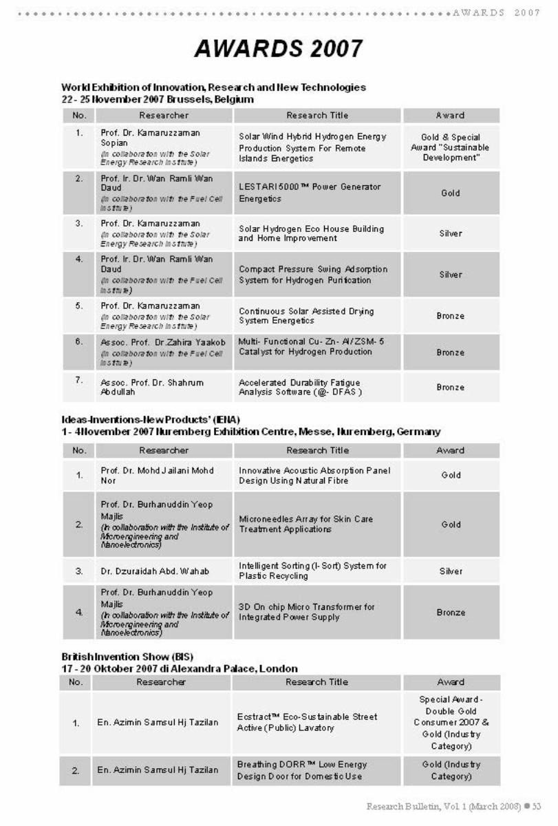
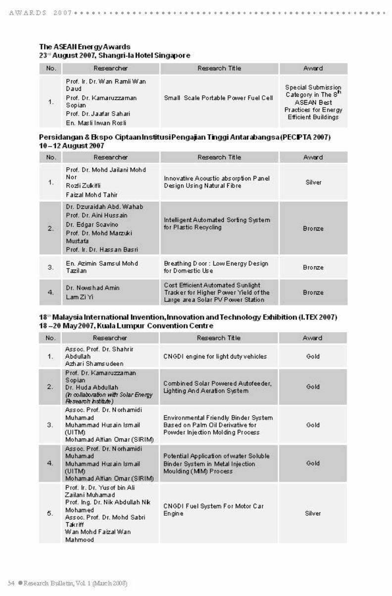
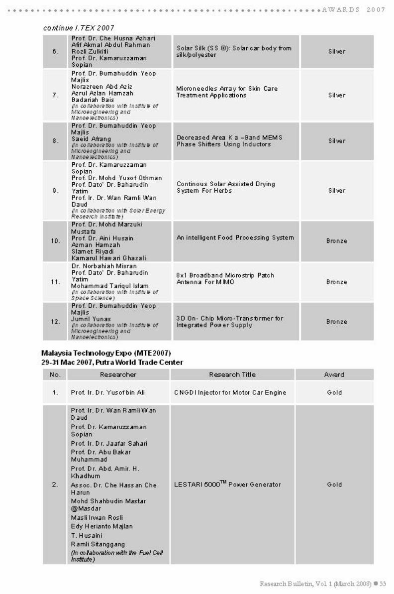
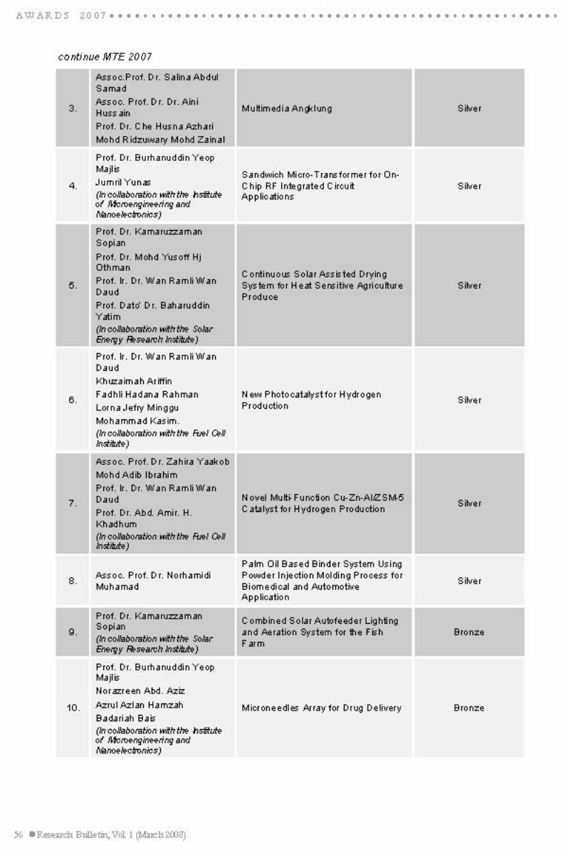
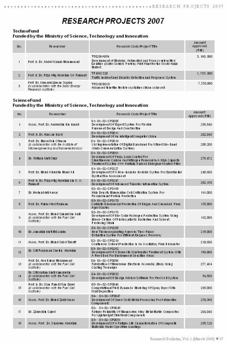
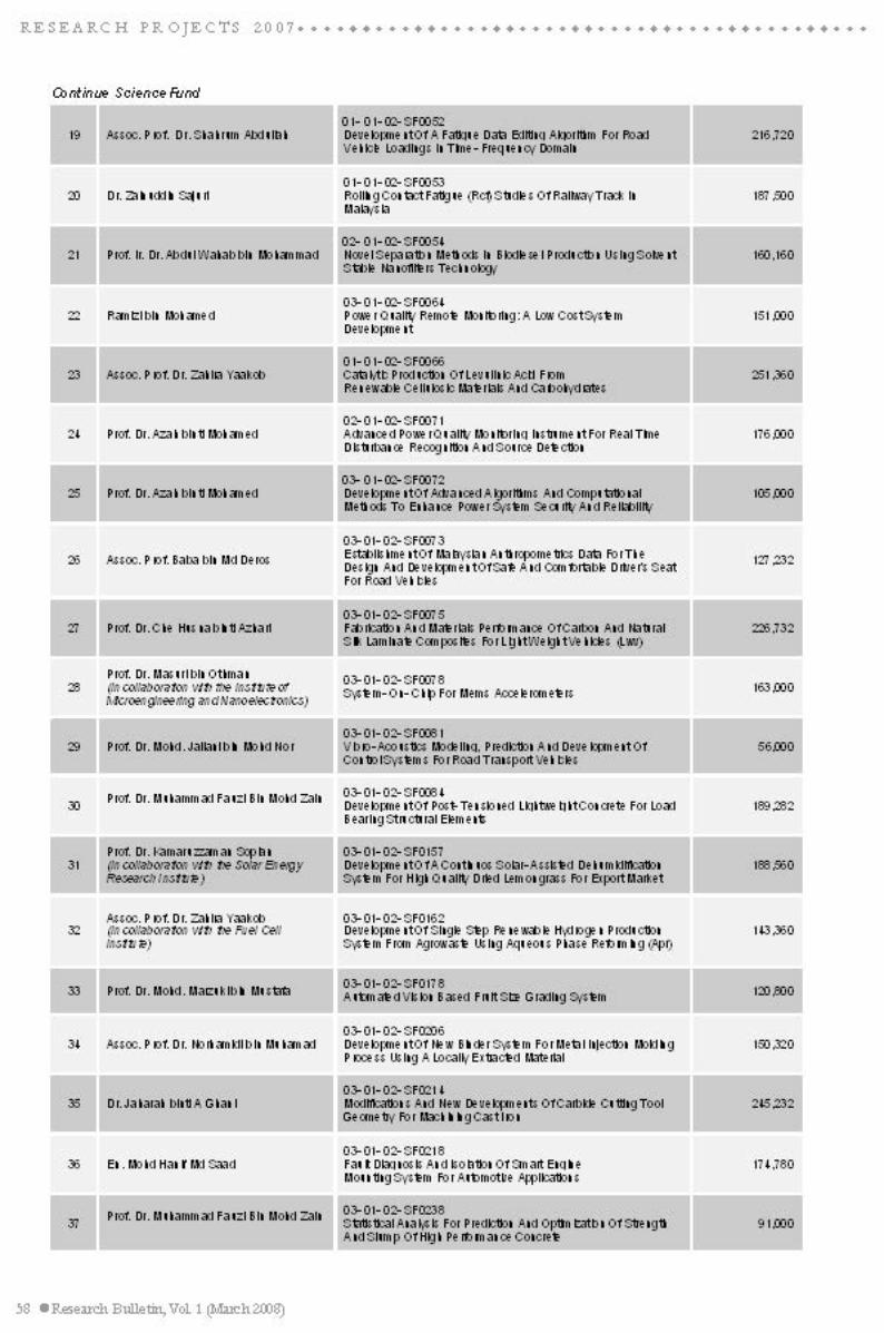
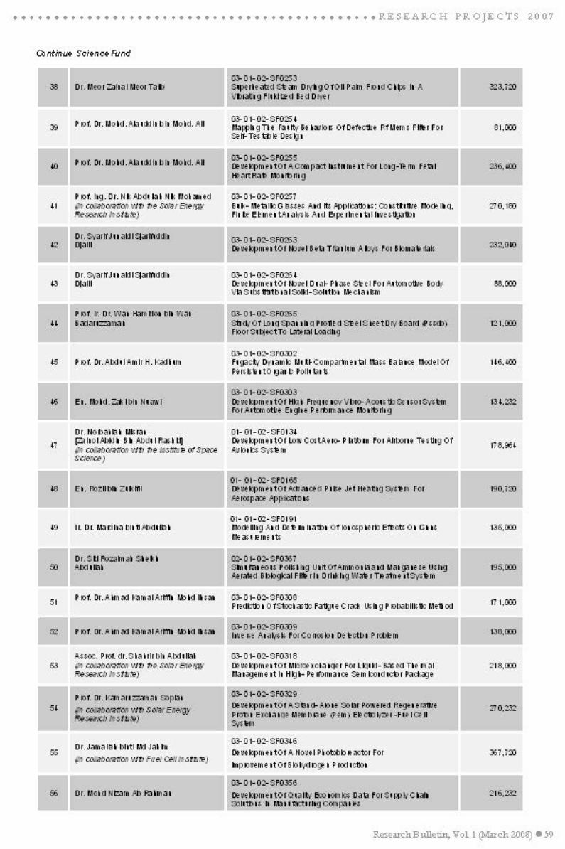
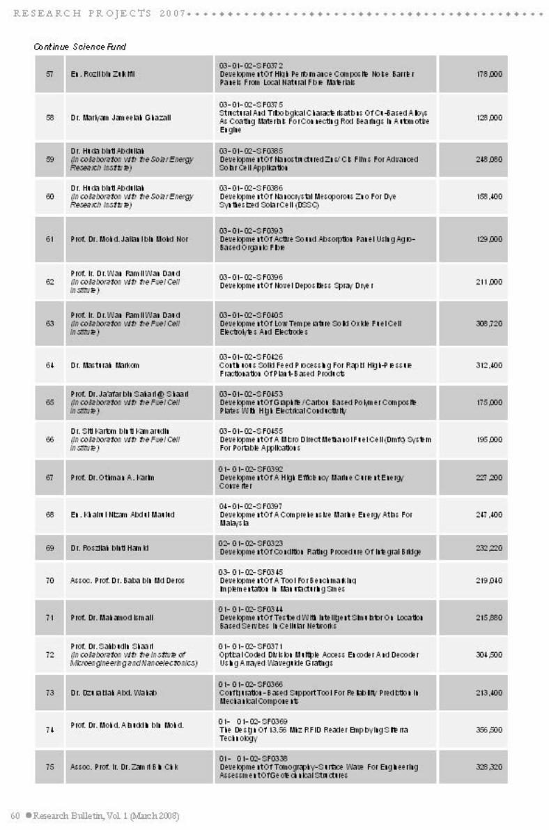


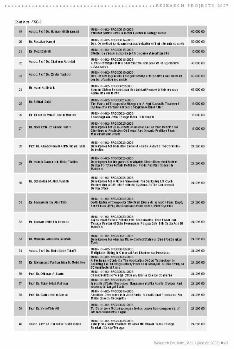
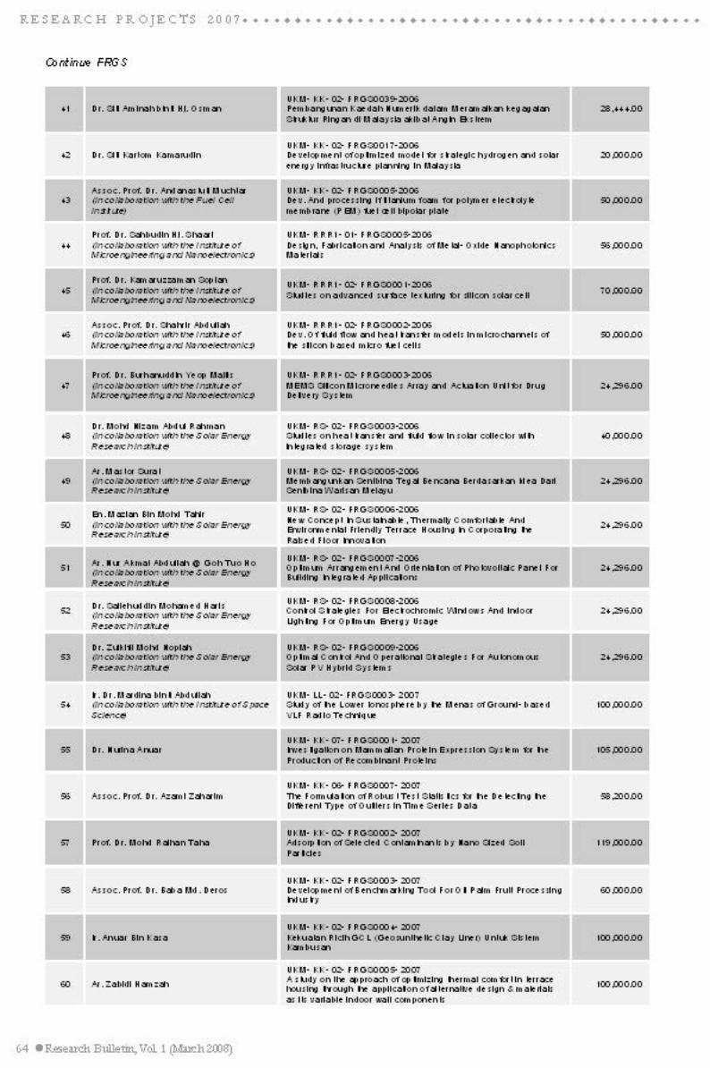

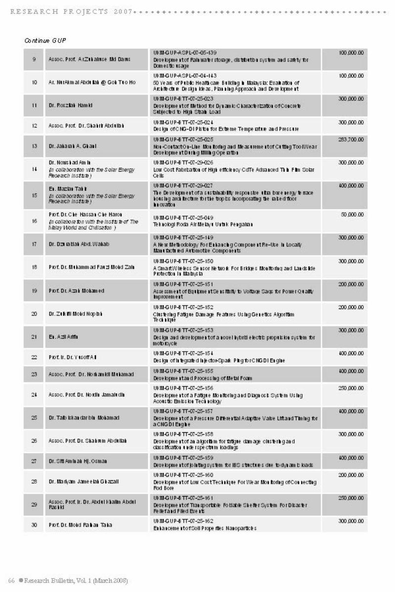
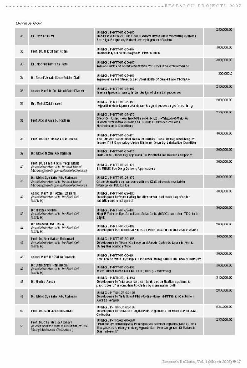
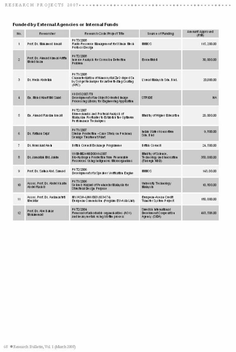


![PROFESSOR AND DEAN (ALUMNI AFFAIRS) - dtu.ac.in · Pravir Kumar CV JULY 2019 [Professor and Dean (AA)] 1 | P a g e PRAVIR KUMAR, PhD PROFESSOR AND DEAN (ALUMNI AFFAIRS) SALIENT FEATURES](https://img.dokumen.tips/doc/110x75/5e13a9335d898e40aa5f01d9/professor-and-dean-alumni-affairs-dtuacin-pravir-kumar-cv-july-2019-professor.jpg)