Embed Size (px)
Citation preview

PROOF 1 2 3 4 5 6
P A R T O N E
Papers

PROOF 1 2 3 4 5 6
3
PROOF 1 2 3 4 5 6
Abstract The Panel Paintings Initiative (PPI) was launched with a Needs Assessment
Survey designed to create a cross section of the current needs and capacity in the field of panel paintings conservation. Through interviews, on-site visits, and questionnaires, factual information about the existing conservation training institutions and the major collections of panel paintings in Europe (including eastern Europe and Russia) and the United States was collected. The survey will provide a better understanding of the collections of panel paintings and will seek to give a general view of the need for structural treatment of panel paintings and related works of art, as well as help determine the need for a more specialized training in this field. As part of the survey, an in-depth litera-ture search was carried out to identify published and unpublished literature on the structural treatment of panel paintings and related wooden objects, to be compiled in a bibliography and made available online. The interim results of the survey have shown a general and strong need for sharing expertise and developing further training opportunities in the structural conservation of panel paintings, in order to transfer knowledge from existing experts to a younger generation.
The aim of the Panel Paintings Initiative (PPI) is to increase spe-cialized training in the structural conservation of panel paint-ings and to advance the treatment of these works in collections
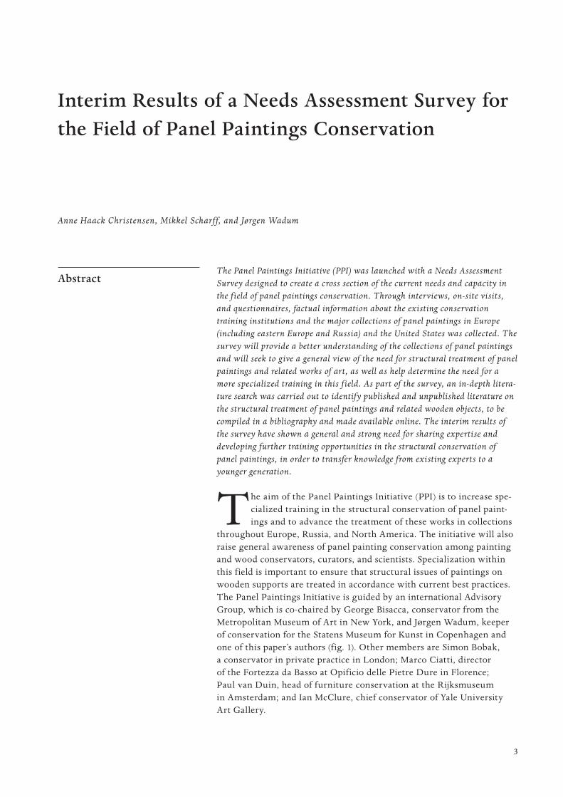
throughout Europe, Russia, and North America. The initiative will also raise general awareness of panel painting conservation among painting and wood conservators, curators, and scientists. Specialization within this field is important to ensure that structural issues of paintings on wooden supports are treated in accordance with current best practices. The Panel Paintings Initiative is guided by an international Advisory Group, which is co-chaired by George Bisacca, conservator from the Metropolitan Museum of Art in New York, and Jørgen Wadum, keeper of conservation for the Statens Museum for Kunst in Copenhagen and one of this paper’s authors (fig. 1). Other members are Simon Bobak, a conservator in private practice in London; Marco Ciatti, director of the Fortezza da Basso at Opificio delle Pietre Dure in Florence; Paul van Duin, head of furniture conservation at the Rijksmuseum in Amsterdam; and Ian McClure, chief conservator of Yale University Art Gallery.
Interim Results of a Needs Assessment Survey for the Field of Panel Paintings Conservation
Anne Haack Christensen, Mikkel Scharff, and Jørgen Wadum
4
PROOF 1 2 3 4 5 6
C h r i s t e n s e n , S c h a r f f , a n d Wa d u m
Introduction The survey for the field of panel paintings conservation in Europe and
in the United States, funded by the PPI through the Getty Foundation, is being carried out under the supervision of the Statens Museum for Kunst, in close collaboration with the Royal Danish Academy of Fine Arts School of Conservation, both in Copenhagen. Members of the PPI Advisory Group and other experts conduct a survey of major art collec-tions and training programs, which is undertaken through personal interviews and questionnaires. The survey involves the gathering of fac-tual information about the collections in Europe, Russia, and the United States that hold significant numbers of panel paintings. Existing conser-vation training institutions are also being surveyed with regard to the past and/or current training efforts of this discipline and related fields—such as, for example, historic interiors, musical instruments, and furni-ture. As part of the Needs Assessment Survey, a literature bibliography is being developed that includes published and unpublished literature on the structural treatment of panel paintings and related subjects.
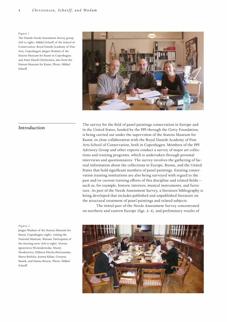
The initial part of the Needs Assessment Survey concentrated on northern and eastern Europe (figs. 2–4), and preliminary results of
F ig u re 2
Jørgen Wadum of the Statens Museum for Kunst, Copenhagen (right), visiting the National Museum, Warsaw. Participants of the meeting were (left to right): Dorota Ignatowicz-Wozniakowska, Maciej Monkiewicz, Elzbieta Pilecka-Pietrusinska, Marta Bielicka, Joanna Kilian, Grazyna Bastek, and Hanna Benesz. Photo: Mikkel Scharff.
Figure 1
The Danish Needs Assessment Survey group (left to right): Mikkel Scharff of the School of Conservation, Royal Danish Academy of Fine Arts, Copenhagen; Jørgen Wadum of the Statens Museum for Kunst in Copenhagen; and Anne Haack Christensen, also from the Statens Museum for Kunst. Photo: Mikkel Scharff.
5
PROOF 1 2 3 4 5 6
I n t e r i m R e s u lt s o f a N e e d s A s s e s s m e n t S u r v e y f o r t h e F i e l d o f Pa n e l Pa i n t i n g s C o n s e r va t i o n
the survey of this vast region were presented at the panel paintings sym-posium “Facing the Challenges of Panel Paintings Conservation: Trends, Treatments, and Training,” held in Los Angeles in May 2009. A final report, which will be submitted to the Getty Foundation and the PPI project partners, will also include findings on the state of panel paint-ings conservation in museums, collections, and training institutions in western and southern Europe, the United Kingdom, Russia, and the United States.
Methods of Collecting Information
Three different questionnaires have been designed for dissemination to conservators and curators in museums and collections, to conserva - tion training programs, and to conservation studios and institutes. Questionnaires are distributed by e-mail to institutions and training pro-grams before visits and interviews are undertaken, and they are also sent to institutions and programs that will not be visited during this survey. Through the website of CODART—an international network for curators of art from the Low Countries—contact persons at museums and collec-tions have been identified. Through the websites of the various institu-tions, additional contacts have been located, in order to distribute questionnaires or arrange meetings with both curators and conservators.
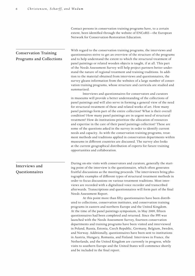
F ig u re 4
Mikkel Scharff of the School of Conservation, Royal Danish Academy of Fine Arts, Copenhagen (right), visiting the Academy of Fine Arts, Prague. He interviews Theodora Popova and Karel Stretti. Photo: Jørgen Wadum.
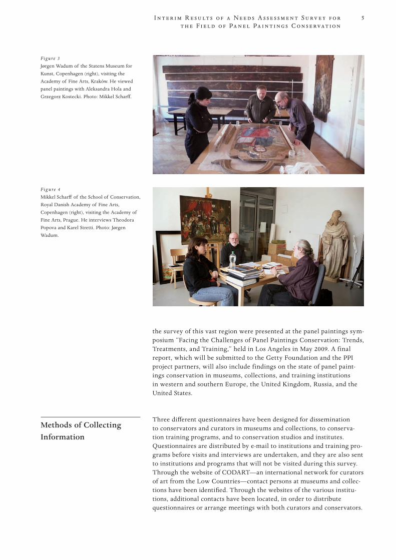
Figure 3
Jørgen Wadum of the Statens Museum for Kunst, Copenhagen (right), visiting the Academy of Fine Arts, Kraków. He viewed panel paintings with Aleksandra Hola and Grzegorz Kostecki. Photo: Mikkel Scharff.
6
PROOF 1 2 3 4 5 6
C h r i s t e n s e n , S c h a r f f , a n d Wa d u m
Contact persons in conservation training programs have, to a certain extent, been identified through the website of ENCoRE—the European Network for Conservation-Restoration Education.
Conservation Training Programs and Collections
With regard to the conservation training programs, the interviews and questionnaires strive to get an overview of the structure of the programs and to help understand the extent to which the structural treatment of panel paintings or related wooden objects is taught, if at all. This part of the Needs Assessment Survey will help project partners better under-stand the nature of regional treatment and training traditions. In addi-tion to the material obtained from interviews and questionnaires, the survey gleans information from the websites of a large number of conser-vation training programs, whose structure and curricula are studied and summarized.
Interviews and questionnaires for conservators and curators in museums will provide a better understanding of the collections of panel paintings and will also serve in forming a general view of the need for structural treatment of these and related works of art. How many panel paintings form part of the entire collection? What is their overall condition? How many panel paintings are in urgent need of structural treatment? How do institutions prioritize the allocation of resources and expertise in the care of their panel paintings collection? These are some of the questions asked in the survey in order to identify current needs and capacity. As with the conservation training programs, treat-ment methods and traditions applied in conservation departments within museums in different countries are discussed. The survey also looks at the current geographical distribution of experts for future training opportunities and collaboration.
Interviews and Questionnaires
During on-site visits with conservators and curators, generally the start-ing point of the interview is the questionnaire, which often generates fruitful discussions as the meeting proceeds. The interviewers bring pho-tographic examples of different types of structural treatment methods in order to focus discussions on various treatment traditions. Most inter-views are recorded with a digitalized voice recorder and transcribed afterwards. Transcriptions and questionnaires will form part of the final Needs Assessment Report.
At this point more than fifty questionnaires have been distrib-uted to collections, conservation institutes, and conservation training programs in eastern and northern Europe and the United Kingdom. At the time of the panel paintings symposium, in May 2009, fifteen questionnaires had been completed and returned. Since the PPI was launched with the Needs Assessment Survey, fourteen conservation departments and training programs have been visited and interviewed in Poland, Russia, Estonia, Czech Republic, Germany, Belgium, Sweden, and Norway. Additionally, questionnaires have been sent to institutions in Austria, Hungary, Romania, and Finland. Interviews in France, the Netherlands, and the United Kingdom are currently in progress, while visits to southern Europe and the United States will commence shortly and be included in the final report.
7
PROOF 1 2 3 4 5 6
I n t e r i m R e s u lt s o f a N e e d s A s s e s s m e n t S u r v e y f o r t h e F i e l d o f Pa n e l Pa i n t i n g s C o n s e r va t i o n
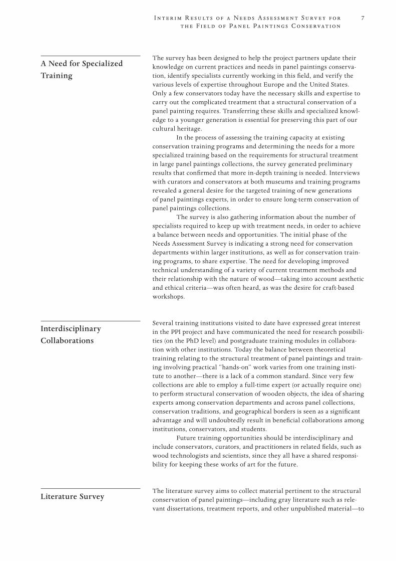
A Need for Specialized Training
The survey has been designed to help the project partners update their knowledge on current practices and needs in panel paintings conserva-tion, identify specialists currently working in this field, and verify the various levels of expertise throughout Europe and the United States. Only a few conservators today have the necessary skills and expertise to carry out the complicated treatment that a structural conservation of a panel painting requires. Transferring these skills and specialized knowl-edge to a younger generation is essential for preserving this part of our cultural heritage.
In the process of assessing the training capacity at existing conservation training programs and determining the needs for a more specialized training based on the requirements for structural treatment in large panel paintings collections, the survey generated preliminary results that confirmed that more in-depth training is needed. Interviews with curators and conservators at both museums and training programs revealed a general desire for the targeted training of new generations of panel paintings experts, in order to ensure long-term conservation of panel paintings collections.
The survey is also gathering information about the number of specialists required to keep up with treatment needs, in order to achieve a balance between needs and opportunities. The initial phase of the Needs Assessment Survey is indicating a strong need for conservation departments within larger institutions, as well as for conservation train-ing programs, to share expertise. The need for developing improved technical understanding of a variety of current treatment methods and their relationship with the nature of wood—taking into account aesthetic and ethical criteria—was often heard, as was the desire for craft-based workshops.
Interdisciplinary Collaborations
Several training institutions visited to date have expressed great interest in the PPI project and have communicated the need for research possibili-ties (on the PhD level) and postgraduate training modules in collabora-tion with other institutions. Today the balance between theoretical training relating to the structural treatment of panel paintings and train-ing involving practical “hands-on” work varies from one training insti-tute to another—there is a lack of a common standard. Since very few collections are able to employ a full-time expert (or actually require one) to perform structural conservation of wooden objects, the idea of sharing experts among conservation departments and across panel collections, conservation traditions, and geographical borders is seen as a significant advantage and will undoubtedly result in beneficial collaborations among institutions, conservators, and students.
Future training opportunities should be interdisciplinary and include conservators, curators, and practitioners in related fields, such as wood technologists and scientists, since they all have a shared responsi-bility for keeping these works of art for the future.
Literature Survey The literature survey aims to collect material pertinent to the structural
conservation of panel paintings—including gray literature such as rele-vant dissertations, treatment reports, and other unpublished material—to
8
PROOF 1 2 3 4 5 6
C h r i s t e n s e n , S c h a r f f , a n d Wa d u m
gain a thorough overview of developments within the field. Because the structural issues of wood panels are similar across several disciplines, the bibliography will also include related literature on the conservation of furniture and musical instruments, lacquer on panels, and painted wooden interiors, as well as literature on the history of panel paintings conservation, relevant technical art history, wood technology, wood identification, and preventive conservation.
The bibliography currently holds about seven hundred refer-ences, which mainly consist of published literature identified in existing searchable online databases such as AATA Online, the Getty Research Library Catalog, ICCROM Library Catalogue, BCIN (Bibliographic Database of the Conservation Information Network), and WorldCat. In addition, relevant unpublished literature is being captured from search-able databases on websites of conservation training programs, and it is being requested from training programs as well. At present, more than twenty training institutions and/or their institution libraries have been contacted with the purpose of capturing relevant student work on the structural treatment of panel paintings and related wooden objects. There are around sixty references currently compiled of unpublished material to be included in the bibliography.
The literature material is being captured in a database that will be made available as an online bibliography on the website of the Getty Conservation Institute. The literature database will be one of several online resources produced for an audience of conservation specialists.
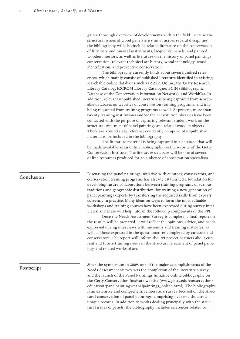
Conclusion Discussing the panel paintings initiative with curators, conservators, and
conservation training programs has already established a foundation for developing future collaborations between training programs of various traditions and geographic distribution, for training a new generation of panel paintings experts by transferring the required skills from experts currently in practice. Many ideas on ways to form the most valuable workshops and training courses have been expressed during survey inter-views, and these will help inform the follow-up components of the PPI.
Once the Needs Assessment Survey is complete, a final report on the results will be prepared. It will reflect the opinions, advice, and needs expressed during interviews with museums and training institutes, as well as those expressed in the questionnaires completed by curators and conservators. The report will inform the PPI project partners about cur-rent and future training needs in the structural treatment of panel paint-ings and related works of art.
Postscript Since the symposium in 2009, one of the major accomplishments of the
Needs Assessment Survey was the completion of the literature survey and the launch of the Panel Paintings Initiative online bibliography on the Getty Conservation Institute website (www.getty.edu/conservation/education/panelpaintings/panelpaintings_online.html). The bibliography is an extensive and comprehensive literature survey focused on the struc-tural conservation of panel paintings, comprising over one thousand unique records. In addition to works dealing principally with the struc-tural issues of panels, the bibliography includes references related to
9
PROOF 1 2 3 4 5 6
I n t e r i m R e s u lt s o f a N e e d s A s s e s s m e n t S u r v e y f o r t h e F i e l d o f Pa n e l Pa i n t i n g s C o n s e r va t i o n
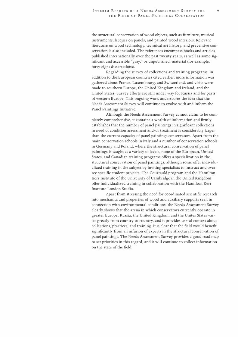
the structural conservation of wood objects, such as furniture, musical instruments, lacquer on panels, and painted wood interiors. Relevant literature on wood technology, technical art history, and preventive con-servation is also included. The references encompass books and articles published internationally over the past twenty years, as well as some sig-nificant and accessible “gray,” or unpublished, material (for example, forty-eight dissertations).
Regarding the survey of collections and training programs, in addition to the European countries cited earlier, more information was gathered about France, Luxembourg, and Switzerland, and visits were made to southern Europe, the United Kingdom and Ireland, and the United States. Survey efforts are still under way for Russia and for parts of western Europe. This ongoing work underscores the idea that the Needs Assessment Survey will continue to evolve with and inform the Panel Paintings Initiative.
Although the Needs Assessment Survey cannot claim to be com-pletely comprehensive, it contains a wealth of information and firmly establishes that the number of panel paintings in significant collections in need of condition assessment and/or treatment is considerably larger than the current capacity of panel paintings conservators. Apart from the main conservation schools in Italy and a number of conservation schools in Germany and Poland, where the structural conservation of panel paintings is taught at a variety of levels, none of the European, United States, and Canadian training programs offers a specialization in the structural conservation of panel paintings, although some offer individu-alized training in the subject by inviting specialists to instruct and over-see specific student projects. The Courtauld program and the Hamilton Kerr Institute of the University of Cambridge in the United Kingdom offer individualized training in collaboration with the Hamilton Kerr Institute London Studio.
Apart from stressing the need for coordinated scientific research into mechanics and properties of wood and auxiliary supports seen in connection with environmental conditions, the Needs Assessment Survey clearly shows that the arena in which conservators currently operate in greater Europe, Russia, the United Kingdom, and the Unites States var-ies greatly from country to country, and it provides useful context about collections, practices, and training. It is clear that the field would benefit significantly from an infusion of experts in the structural conservation of panel paintings. The Needs Assessment Survey provides a good road map to set priorities in this regard, and it will continue to collect information on the state of the field.
10
PROOF 1 2 3 4 5 6
Abstract Albrecht Dürer’s Adam and Eve were painted in 1507 on two separate panels,
but they are to be considered a single work of art. Scant documentary evidence indicates that the panels have always been together and received conservation treatments in 1853, 1937, and 1972. The two panels appear to have undergone near-identical treatments until 1972, when it seems that the Adam panel alone was thinned and heavily cradled. The Eve panel, by contrast, retains its origi-nal thickness, including a porphyry imitation on the reverse. While each panel had two or three major splits, which were already visible in nineteenth-century photographs, the Adam panel has developed at least fifty new splits since hav-ing been cradled.
The treatment of the two panels was undertaken at the Prado Museum between October 2008 and May 2009. There was a relatively minor intervention on the Eve panel, including the removal of three later crosspieces and the repair of a few splits. The treatment of the Adam panel entailed the removal of the cradle and the repair of several dozen splits by the insertion of narrow wedges. A curved secondary support strainer was then constructed and attached with new spring mechanisms that were developed during the course of the past year.
The two famous panel paintings by Albrecht Dürer depicting Adam and Eve were treated at the Museo Nacional del Prado (Prado Museum) in Madrid in the fall of 2008 and the spring of
2009 (fig. 1). The treatment was complicated by the considerable disparity in the state of the panels—one retained its original thickness and surface coating, while the other was thinned and heavily cradled (fig. 2).
The project was the most recent in a series of collaborations between the Metropolitan Museum of Art in New York and the Prado Museum, begun over twenty years ago in 1990 with the treatment of the great Descent from the Cross by Rogier van der Weyden and The Three Graces by Peter Paul Rubens, completed in 1997.
The conservation of the Dürer panels represents the first major project of the Getty Panel Painting Initiative (PPI). The project was ide-ally suited to the PPI because it addressed many of its key areas of focus:
• tofostercollaborativeeffortsbetweenmajorinstitutions• tofacilitatethetreatmentofamajorworkofart• topromoteexchangebetweenrecognizedexperts• toprovideintensivetrainingformorejuniorspecialists
The Treatment of Dürer’s Adam and Eve Panels at the Prado Museum
George Bisacca and José de la Fuente Martínez
11Th e Tr e a t m e n t o f D ü r e r’s A d a m a n d E v e Pa n e l s a t t h e P r a d o M u s e u m
PROOF 1 2 3 4 5 6
• toprovideassistancetothestaffofothermajorcollectionsinthecareof panel paintings
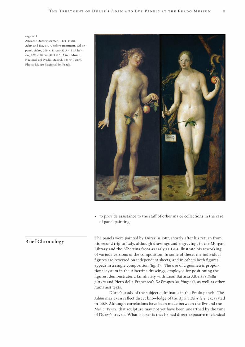
Brief Chronology The panels were painted by Dürer in 1507, shortly after his return from
his second trip to Italy, although drawings and engravings in the Morgan Library and the Albertina from as early as 1504 illustrate his reworking of various versions of the composition. In some of these, the individual figures are reversed on independent sheets, and in others both figures appear in a single composition (fig. 3). The use of a geometric propor-tional system in the Albertina drawings, employed for positioning the figures, demonstrates a familiarity with Leon Battista Alberti’s Della pittura and Piero della Francesca’s De Prospectiva Pingendi, as well as other humanist texts.
Dürer’s study of the subject culminates in the Prado panels. The Adam may even reflect direct knowledge of the Apollo Belvedere, excavated in 1489. Although correlations have been made between the Eve and the Medici Venus, that sculpture may not yet have been unearthed by the time of Dürer’s travels. What is clear is that he had direct exposure to classical
Figure 1
Albrecht Dürer (German, 1471–1528), Adam and Eve, 1507, before treatment. Oil on panel, Adam, 209 × 81 cm (82.3 × 31.9 in.); Eve, 209 × 80 cm (82.3 × 31.5 in.). Museo Nacional del Prado, Madrid, P2177, P2178. Photo: Museo Nacional del Prado.
12
PROOF 1 2 3 4 5 6
B i s a c c a a n d d e l a F u e n t e M a r t í n e z
sculpture in Italy, and this knowledge was pivotal to his development as an artist. Upon his return to Germany, Dürer became a fundamental conduit for the diffusion of Italian humanist ideas north of the Alps.
Although the brief chronology dates the panels to 1507, it is not clear whether or not they were commissioned by the Municipality of Nuremburg or simply given by Dürer to the city in that year. In the late sixteenth century, they were given to Rudolf II and taken to Prague Castle, where they remained until 1648, when they were appropriated by the Swedes after their siege of the city. Christina of Sweden, how-ever, never having cared much for German painting, gave the pair to Philip IV in 1655.
The panels survived the fire at the Alcázar in Madrid in 1734 but were again threatened by fire when Carlos III decided to have them burned in 1762 because of their indecent nudity. Fortunately, court painter Anton Rafael Mengs persuaded the Marquis de Esquilache against the move, claiming that he could use them for teaching anatomy to his students at the Academia de San Fernando, where they were eventually moved in 1792. In 1827 they were transferred to the Prado; however, they were relegated for another decade to the Sala Reservada, where nudes were quarantined for fear that they might corrupt public
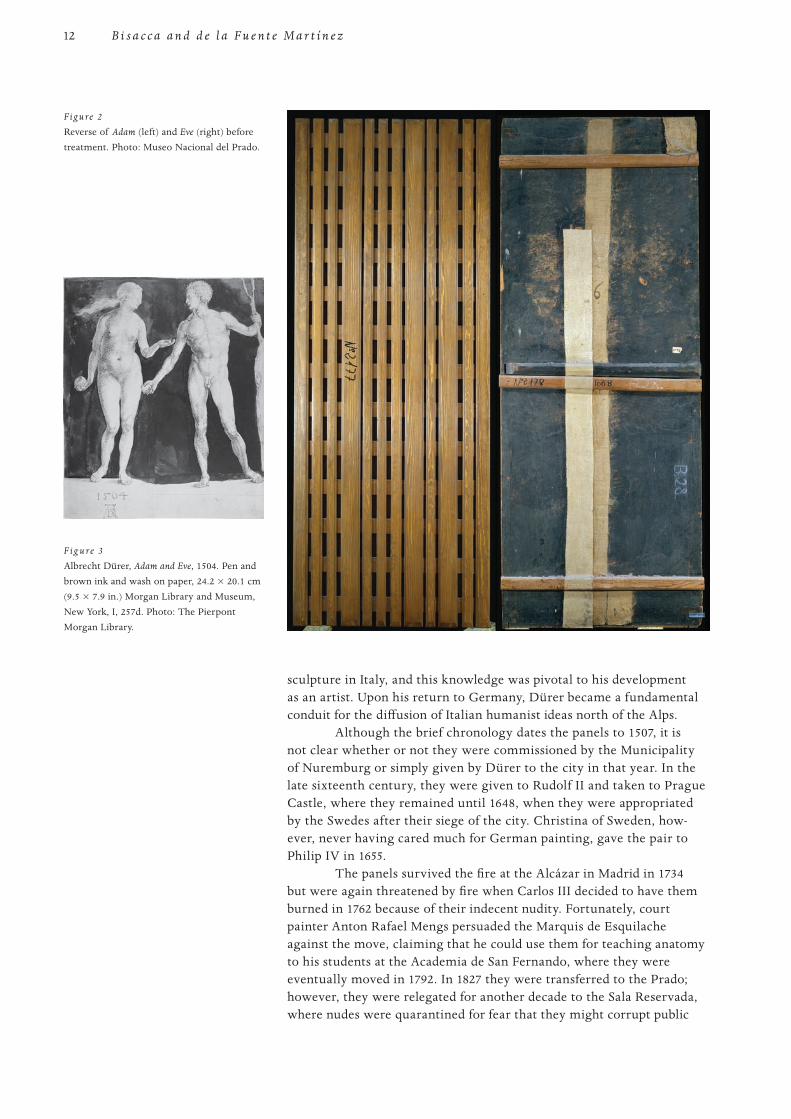
F ig u re 3
Albrecht Dürer, Adam and Eve, 1504. Pen and brown ink and wash on paper, 24.2 × 20.1 cm (9.5 × 7.9 in.) Morgan Library and Museum, New York, I, 257d. Photo: The Pierpont Morgan Library.
Figure 2
Reverse of Adam (left) and Eve (right) before treatment. Photo: Museo Nacional del Prado.
13Th e Tr e a t m e n t o f D ü r e r’s A d a m a n d E v e Pa n e l s a t t h e P r a d o M u s e u m
PROOF 1 2 3 4 5 6
morality. In 1838 they were finally integrated into the permanent collec-tion by school and chronology.
Between 1936 and 1938, during the Spanish Civil War, twenty-two shipments of 391 Prado paintings were sent to the fortified medieval Torres Serrano outside Valencia to keep them out of harm’s way. Then, in February 1939, they were sent to Geneva, where they were exhib-ited publicly. On September 5 of that year, four days after the outbreak of World War II, they were again packed and shipped by train back to Madrid and the Prado.
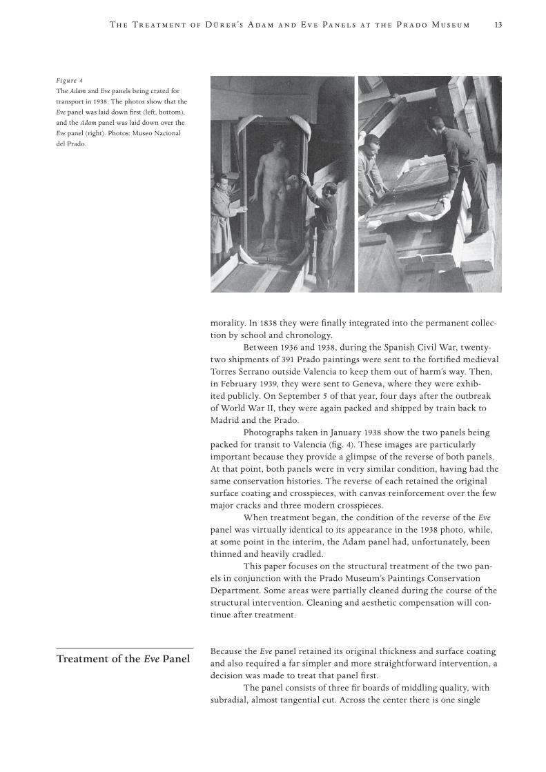
Photographs taken in January 1938 show the two panels being packed for transit to Valencia (fig. 4). These images are particularly important because they provide a glimpse of the reverse of both panels. At that point, both panels were in very similar condition, having had the same conservation histories. The reverse of each retained the original surface coating and crosspieces, with canvas reinforcement over the few major cracks and three modern crosspieces.
When treatment began, the condition of the reverse of the Eve panel was virtually identical to its appearance in the 1938 photo, while, at some point in the interim, the Adam panel had, unfortunately, been thinned and heavily cradled.
This paper focuses on the structural treatment of the two pan-els in conjunction with the Prado Museum’s Paintings Conservation Department. Some areas were partially cleaned during the course of the structural intervention. Cleaning and aesthetic compensation will con-tinue after treatment.
Treatment of the Eve Panel Because the Eve panel retained its original thickness and surface coating
and also required a far simpler and more straightforward intervention, a decision was made to treat that panel first.
The panel consists of three fir boards of middling quality, with subradial, almost tangential cut. Across the center there is one single
Figure 4
The Adam and Eve panels being crated for transport in 1938. The photos show that the Eve panel was laid down first (left, bottom), and the Adam panel was laid down over the Eve panel (right). Photos: Museo Nacional del Prado.
14
PROOF 1 2 3 4 5 6
B i s a c c a a n d d e l a F u e n t e M a r t í n e z
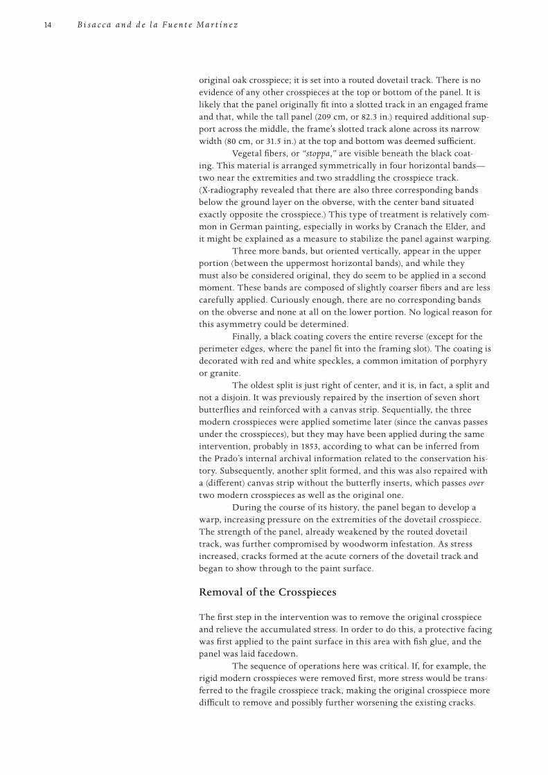
original oak crosspiece; it is set into a routed dovetail track. There is no evidence of any other crosspieces at the top or bottom of the panel. It is likely that the panel originally fit into a slotted track in an engaged frame and that, while the tall panel (209 cm, or 82.3 in.) required additional sup-port across the middle, the frame’s slotted track alone across its narrow width (80 cm, or 31.5 in.) at the top and bottom was deemed sufficient.
Vegetal fibers, or “stoppa,” are visible beneath the black coat-ing. This material is arranged symmetrically in four horizontal bands—two near the extremities and two straddling the crosspiece track. (X-radiography revealed that there are also three corresponding bands below the ground layer on the obverse, with the center band situated exactly opposite the crosspiece.) This type of treatment is relatively com-mon in German painting, especially in works by Cranach the Elder, and it might be explained as a measure to stabilize the panel against warping.
Three more bands, but oriented vertically, appear in the upper portion (between the uppermost horizontal bands), and while they must also be considered original, they do seem to be applied in a second moment. These bands are composed of slightly coarser fibers and are less carefully applied. Curiously enough, there are no corresponding bands on the obverse and none at all on the lower portion. No logical reason for this asymmetry could be determined.
Finally, a black coating covers the entire reverse (except for the perimeter edges, where the panel fit into the framing slot). The coating is decorated with red and white speckles, a common imitation of porphyry or granite.
The oldest split is just right of center, and it is, in fact, a split and not a disjoin. It was previously repaired by the insertion of seven short butterflies and reinforced with a canvas strip. Sequentially, the three modern crosspieces were applied sometime later (since the canvas passes under the crosspieces), but they may have been applied during the same intervention, probably in 1853, according to what can be inferred from the Prado’s internal archival information related to the conservation his-tory. Subsequently, another split formed, and this was also repaired with a (different) canvas strip without the butterfly inserts, which passes over two modern crosspieces as well as the original one.
During the course of its history, the panel began to develop a warp, increasing pressure on the extremities of the dovetail crosspiece. The strength of the panel, already weakened by the routed dovetail track, was further compromised by woodworm infestation. As stress increased, cracks formed at the acute corners of the dovetail track and began to show through to the paint surface.
Removal of the Crosspieces
The first step in the intervention was to remove the original crosspiece and relieve the accumulated stress. In order to do this, a protective facing was first applied to the paint surface in this area with fish glue, and the panel was laid facedown.
The sequence of operations here was critical. If, for example, the rigid modern crosspieces were removed first, more stress would be trans-ferred to the fragile crosspiece track, making the original crosspiece more difficult to remove and possibly further worsening the existing cracks.
15Th e Tr e a t m e n t o f D ü r e r’s A d a m a n d E v e Pa n e l s a t t h e P r a d o M u s e u m
PROOF 1 2 3 4 5 6
Incisions were made through the canvas strip fixed across the crosspiece. Next, by placing the end of a sash clamp on one end of the original crosspiece, and the other, slightly diagonally, onto the end of the modern crosspiece, the crosspiece could be safely pushed out without tapping, simply by tightening the clamp.
The modern crosspieces were not routed into the panel. X-rays revealed that they were attached by screws, which, remarkably, were inserted from the obverse through the paint film. Acetone was used to expose the fillings over the screw heads. The logic must have been that the tapering screw tips would have pulled out of the thin panel under the accumulated stress buildup, but by having the head of the screw on one side of the panel and the shaft sunk deep into the thicker cross-piece on the reverse, the strength of the hold was far greater. As brutal as this appears, at least care was taken in the placement of the screws. There are four holes at the top and four at the bottom, and five across the middle. This placement seems to be guided by a conscious effort to situate the holes in the least obtrusive, easy-to-retouch areas. The upper holes all fall in the black background, and the lower ones are in rocks or the tree trunk. The addition of a fifth hole in the middle band made it possible to avoid situating a hole in the more difficult-to-match f lesh tones.
When the fillings were removed, the screw heads were found to tilt inward toward the center of the panel and were pulled under the original paint surface, so that they could not be extracted without caus-ing further damage. This situation was caused by the cumulative shrink-age of the panel since the modern crosspieces had been applied.
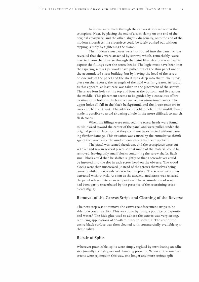
The panel was turned facedown, and the crosspieces were cut with a hand saw in several places so that much of the material could be removed, leaving only small blocks containing the screw shafts. Each small block could then be shifted slightly so that a screwdriver could be inserted into the slot in each screw head on the obverse. The wood blocks were then unscrewed (instead of the screws themselves being turned) while the screwdriver was held in place. The screws were then extracted without risk. As soon as the accumulated stress was released, the panel relaxed into a curved position. The accumulation of warp had been partly exacerbated by the presence of the restraining cross-pieces (fig. 5).
Removal of the Canvas Strips and Cleaning of the Reverse
The next step was to remove the canvas reinforcement strips to be able to access the splits. This was done by using a poultice of Laponite and water.1 The hide glue used to adhere the canvas was very strong, requiring applications of 30–40 minutes to soften it. The rest of the entire black surface was then cleaned with commercially available syn-thetic saliva.
Repair of Splits
Wherever practicable, splits were simply reglued by introducing an adhe-sive (usually codfish glue) and clamping pressure. When all the smaller cracks were rejoined in this way, one longer and more serious split
16
PROOF 1 2 3 4 5 6
B i s a c c a a n d d e l a F u e n t e M a r t í n e z
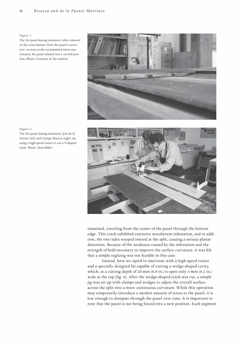
remained, traveling from the center of the panel through the bottom edge. This crack exhibited extensive woodworm infestation, and in addi-tion, the two sides warped inward at the split, causing a serious planar distortion. Because of the weakness caused by the infestation and the strength of hold necessary to improve the surface curvature, it was felt that a simple regluing was not feasible in this case.
Instead, here we opted to intervene with a high-speed router and a specially designed bit capable of cutting a wedge-shaped cavity, which, at a cutting depth of 20 mm (0.8 in.) is open only 4 mm (0.2 in.) wide at the top (fig. 6). After the wedge-shaped track was cut, a simple jig was set up with clamps and wedges to adjust the overall surface across the split into a more continuous curvature. While this operation may temporarily introduce a modest amount of stress to the panel, it is low enough to dissipate through the panel over time. It is important to note that the panel is not being forced into a new position. Each segment
F ig u re 6
The Eve panel during treatment: José de la Fuente (left) and George Bisacca (right) are using a high-speed router to cut a V-shaped track. Photo: Alan Miller.
Figure 5
The Eve panel during treatment, after removal of the cross battens. Note the panel’s curva-ture: as soon as the accumulated stress was released, the panel relaxed into a curved posi-tion. Photo: Courtesy of the authors.
17Th e Tr e a t m e n t o f D ü r e r’s A d a m a n d E v e Pa n e l s a t t h e P r a d o M u s e u m
PROOF 1 2 3 4 5 6
retains the warp it has acquired; it is simply rotated slightly and held in alignment across the split.
Once the surface level and curvature were adjusted, thin wedges could be prepared to fit into the track. When we gained access to the full depth of the split, we could vacuum out the woodworm frass and partly fill the cavities with a paste, Araldite AV/HV 1253, greatly solidifying the entire area and increasing the strength of the repair. The same Araldite also served as an adhesive for the wedges. After curing, the wedges were trimmed to surface level.
Substitution of Butterfly Repair
Although we had decided not to remove the seven nineteenth-century butterf ly repairs because they appeared stable, one split passed through the center of one of the butterf lies, and we decided to replace just that one. Traditionally, butterf ly repairs are made with inserts oriented perpendicular to the grain; this can inhibit expansion and contrac-tion across the grain and, in many cases, actually produce new splits. Whenever old butterf ly repairs are replaced, the cavities are rebuilt with the same wood as the panel, but the inserts are now oriented parallel to the grain.
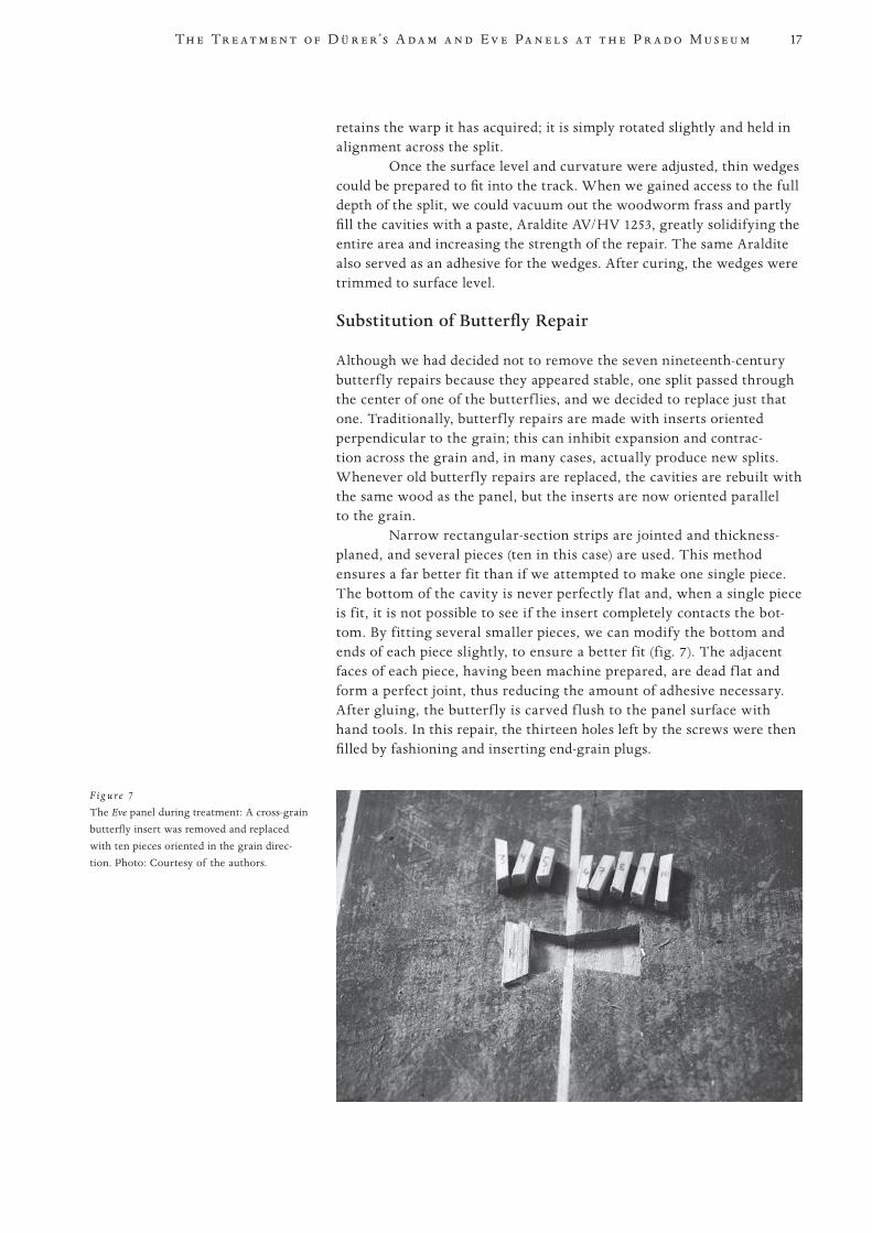
Narrow rectangular-section strips are jointed and thickness-planed, and several pieces (ten in this case) are used. This method ensures a far better fit than if we attempted to make one single piece. The bottom of the cavity is never perfectly f lat and, when a single piece is fit, it is not possible to see if the insert completely contacts the bot-tom. By fitting several smaller pieces, we can modify the bottom and ends of each piece slightly, to ensure a better fit (fig. 7). The adjacent faces of each piece, having been machine prepared, are dead f lat and form a perfect joint, thus reducing the amount of adhesive necessary. After gluing, the butterf ly is carved f lush to the panel surface with hand tools. In this repair, the thirteen holes left by the screws were then filled by fashioning and inserting end-grain plugs.
F ig u re 7
The Eve panel during treatment: A cross-grain butterfly insert was removed and replaced with ten pieces oriented in the grain direc-tion. Photo: Courtesy of the authors.
18
PROOF 1 2 3 4 5 6
B i s a c c a a n d d e l a F u e n t e M a r t í n e z
Modification of the Original Crosspiece
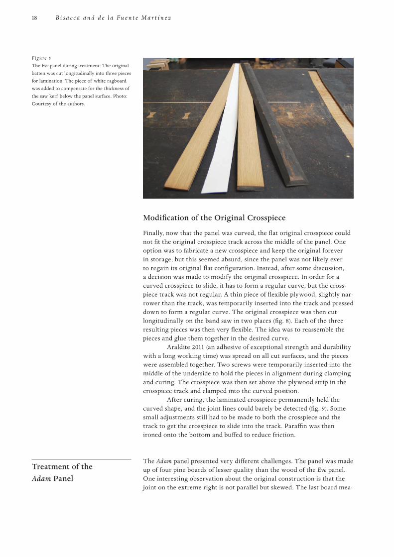
Finally, now that the panel was curved, the flat original crosspiece could not fit the original crosspiece track across the middle of the panel. One option was to fabricate a new crosspiece and keep the original forever in storage, but this seemed absurd, since the panel was not likely ever to regain its original flat configuration. Instead, after some discussion, a decision was made to modify the original crosspiece. In order for a curved crosspiece to slide, it has to form a regular curve, but the cross-piece track was not regular. A thin piece of flexible plywood, slightly nar-rower than the track, was temporarily inserted into the track and pressed down to form a regular curve. The original crosspiece was then cut longitudinally on the band saw in two places (fig. 8). Each of the three resulting pieces was then very flexible. The idea was to reassemble the pieces and glue them together in the desired curve.
Araldite 2011 (an adhesive of exceptional strength and durability with a long working time) was spread on all cut surfaces, and the pieces were assembled together. Two screws were temporarily inserted into the middle of the underside to hold the pieces in alignment during clamping and curing. The crosspiece was then set above the plywood strip in the crosspiece track and clamped into the curved position.
After curing, the laminated crosspiece permanently held the curved shape, and the joint lines could barely be detected (fig. 9). Some small adjustments still had to be made to both the crosspiece and the track to get the crosspiece to slide into the track. Paraffin was then ironed onto the bottom and buffed to reduce friction.
Treatment of the Adam Panel
The Adam panel presented very different challenges. The panel was made up of four pine boards of lesser quality than the wood of the Eve panel. One interesting observation about the original construction is that the joint on the extreme right is not parallel but skewed. The last board mea-
Figure 8
The Eve panel during treatment: The original batten was cut longitudinally into three pieces for lamination. The piece of white ragboard was added to compensate for the thickness of the saw kerf below the panel surface. Photo: Courtesy of the authors.
19Th e Tr e a t m e n t o f D ü r e r’s A d a m a n d E v e Pa n e l s a t t h e P r a d o M u s e u m
PROOF 1 2 3 4 5 6
sures 20 cm (7.9 in.) wide at the bottom and more than 27 cm (10.6 in.) at the top. This phenomenon is relatively common, especially in German panel construction; in fact, it occurs on the Judith with the Head of Holofernes (ca. 1530) by Lucas Cranach the Elder at the Metropolitan Museum, and on the Crucifixion (ca. 1520) by Albrecht Altdorfer at the Szépmüvészeti Múzeum in Budapest, and it also happens to be present on Leonardo da Vinci’s Saint Jerome Praying in the Wilderness (ca. 1482) at the Vatican Pinacoteca.
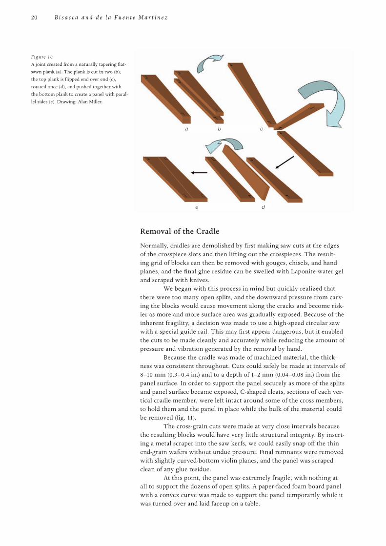
This type of joint can be explained logically as an efficient use of materials. If, for example, two planks were flat-sawn from a trunk and they naturally tapered at one end because of variations in the trunk, a significant amount of material would have to be wasted in order to make perfectly squared rectangular boards. Instead, they could be squared on one side only and the tapering side simply straightened at whatever angle it happened to form. When one board is flipped end over end and rotated once, the result-ing joint will always form the exact complementary angle necessary to com-plete a perfect rectangle with parallel sides and very little waste (fig. 10).
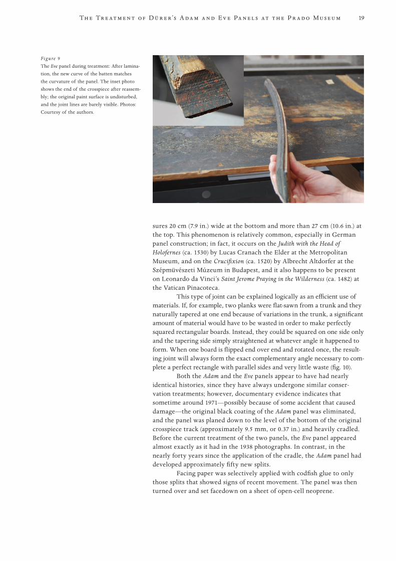
Both the Adam and the Eve panels appear to have had nearly identical histories, since they have always undergone similar conser-vation treatments; however, documentary evidence indicates that sometime around 1971—possibly because of some accident that caused damage—the original black coating of the Adam panel was eliminated, and the panel was planed down to the level of the bottom of the original crosspiece track (approximately 9.5 mm, or 0.37 in.) and heavily cradled. Before the current treatment of the two panels, the Eve panel appeared almost exactly as it had in the 1938 photographs. In contrast, in the nearly forty years since the application of the cradle, the Adam panel had developed approximately fifty new splits.
Facing paper was selectively applied with codfish glue to only those splits that showed signs of recent movement. The panel was then turned over and set facedown on a sheet of open-cell neoprene.
Figure 9
The Eve panel during treatment: After lamina-tion, the new curve of the batten matches the curvature of the panel. The inset photo shows the end of the crosspiece after reassem-bly; the original paint surface is undisturbed, and the joint lines are barely visible. Photos: Courtesy of the authors.
20
PROOF 1 2 3 4 5 6
B i s a c c a a n d d e l a F u e n t e M a r t í n e z
Removal of the Cradle
Normally, cradles are demolished by first making saw cuts at the edges of the crosspiece slots and then lifting out the crosspieces. The result-ing grid of blocks can then be removed with gouges, chisels, and hand planes, and the final glue residue can be swelled with Laponite-water gel and scraped with knives.
We began with this process in mind but quickly realized that there were too many open splits, and the downward pressure from carv-ing the blocks would cause movement along the cracks and become risk-ier as more and more surface area was gradually exposed. Because of the inherent fragility, a decision was made to use a high-speed circular saw with a special guide rail. This may first appear dangerous, but it enabled the cuts to be made cleanly and accurately while reducing the amount of pressure and vibration generated by the removal by hand.
Because the cradle was made of machined material, the thick-ness was consistent throughout. Cuts could safely be made at intervals of 8–10 mm (0.3–0.4 in.) and to a depth of 1–2 mm (0.04–0.08 in.) from the panel surface. In order to support the panel securely as more of the splits and panel surface became exposed, C-shaped cleats, sections of each ver-tical cradle member, were left intact around some of the cross members, to hold them and the panel in place while the bulk of the material could be removed (fig. 11).
The cross-grain cuts were made at very close intervals because the resulting blocks would have very little structural integrity. By insert-ing a metal scraper into the saw kerfs, we could easily snap off the thin end-grain wafers without undue pressure. Final remnants were removed with slightly curved-bottom violin planes, and the panel was scraped clean of any glue residue.
At this point, the panel was extremely fragile, with nothing at all to support the dozens of open splits. A paper-faced foam board panel with a convex curve was made to support the panel temporarily while it was turned over and laid faceup on a table.
Figure 10
A joint created from a naturally tapering flat-sawn plank (a). The plank is cut in two (b), the top plank is flipped end over end (c), rotated once (d), and pushed together with the bottom plank to create a panel with paral-lel sides (e). Drawing: Alan Miller.
a b c
e d
BisaccaFig10.ai
21Th e Tr e a t m e n t o f D ü r e r’s A d a m a n d E v e Pa n e l s a t t h e P r a d o M u s e u m
PROOF 1 2 3 4 5 6
Only a few older major splits had gesso fillings—similar to the number found on the Eve panel. These dated from the 1853 intervention; no new treatment had taken place since the 1971 cradling, and conse-quently, none of the newer splits had been filled. The removal of any fill-ings was important, so that the level of the paint surface across the splits could be aligned accurately.
Most of the splits were too tight to permit the introduction of an adhesive to the full depth. The original surface of the panel had also already been completely eliminated during the application of the cradle, and so, even though a small amount of original material would need to be removed, the strength and durability of the resulting repair seemed to justify the use of the high-speed router that was also used on the large split on the Eve panel.
Special carbide bits, first developed by the Opificio delle Pietre Dure in Florence and produced in Milan, were used to cut the wedge tracks. These bits are capable of cutting very narrow and precise tracks without burning at the tip, ensuring extremely accurate results (fig. 12).
The wood used for the wedge-shaped inserts was nearly identical to the wood of the panel and came from an eighteenth-century stretcher. Insert wedges were prepared in lengths cut with a miniature table saw with a carbide-tipped blade.
Each crack is opened in short straight sections, and several passes are made, proceeding incrementally deeper while the tip is main-tained exactly on the segment of the crack being opened. Once the track is opened, the overall surface curvature can also be adjusted to follow a more uniform curvature, rather than maintaining the “washboard” effect that had developed from the rigidity of the cradle.
Accurate thickness and depth measurements are crucial. Two methods were employed to measure thickness: a fixed-arm microm - eter, where one full revolution of a dial equals 1 mm (0.04 in.), and a Hacklinger thickness gauge, developed for violin makers. The Hacklinger device has a smooth plastic-coated magnetic disk that can be detached and positioned on one side of the panel and held in place by the magnetic end of a calibrated tube on the other. The disk can be dragged along so that the range is not limited to the length of the arms on the micrometer. Both
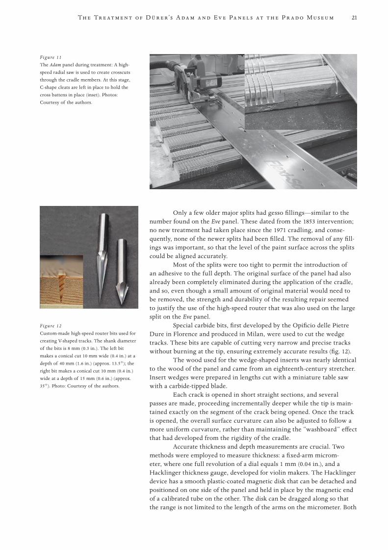
Figure 12
Custom-made high-speed router bits used for creating V-shaped tracks. The shank diameter of the bits is 8 mm (0.3 in.). The left bit makes a conical cut 10 mm wide (0.4 in.) at a depth of 40 mm (1.6 in.) (approx. 13.5°); the right bit makes a conical cut 10 mm (0.4 in.) wide at a depth of 15 mm (0.6 in.) (approx. 35°). Photo: Courtesy of the authors.
Figure 11
The Adam panel during treatment: A high-speed radial saw is used to create crosscuts through the cradle members. At this stage, C-shape cleats are left in place to hold the cross battens in place (inset). Photos: Courtesy of the authors.
22
PROOF 1 2 3 4 5 6
B i s a c c a a n d d e l a F u e n t e M a r t í n e z
instruments are accurate to one-tenth of a millimeter. Simple depth mea-surements into the track with a steel ruler were also made to confirm the depth setting on the router itself.
Many cracks did not pass directly through the panel perpendicu-lar to the surface. In these cases it was necessary to trace the incidence of the crack on the paint surface onto Mylar and transfer it onto the reverse so that the router tip could be more efficiently aligned in advance to cor-respond to the position of the crack at maximum depth.
Smaller splits were treated first, so that the panel gradually gained solidity. This increased the general stability and later facilitated the adjustment and clamping of the larger splits. In all, some 388 indi-vidual wedges were inserted.
The Secondary Support
Because the panel was thin for its size, an additional secondary support was considered necessary. A curved perimeter strainer with five cross members was fabricated to fit the concave curve of the reverse of the panel. The panel was then connected to the strainer by means of spe-cially prepared spring-loaded mechanisms that could regulate future expansion and contraction due to humidity fluctuation. Thin pieces of oak were stack-laminated by the same method that had been employed during modification of the original crosspiece on the Eve panel. Araldite 2011 was spread on all faces, and the slats were arranged symmetrically in five groups across the panel.
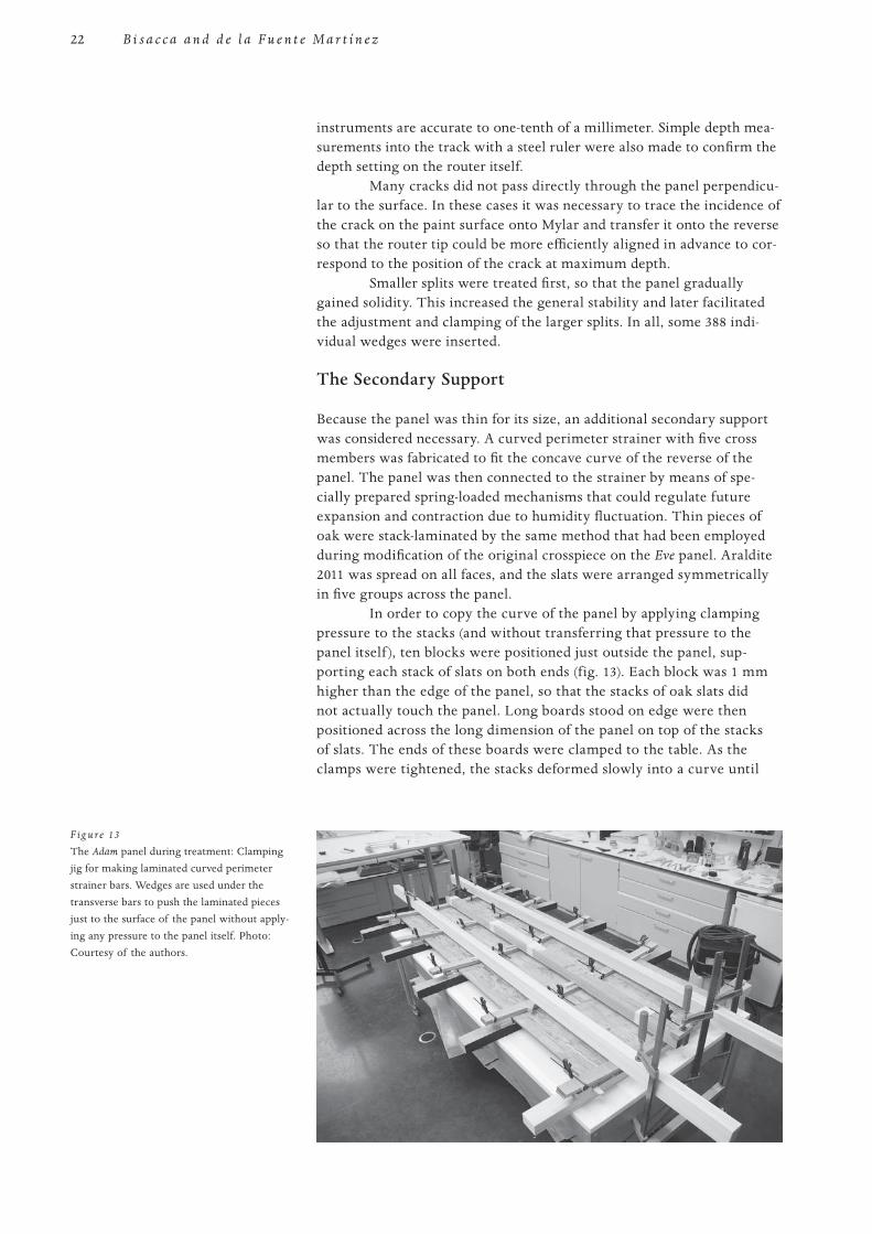
In order to copy the curve of the panel by applying clamping pressure to the stacks (and without transferring that pressure to the panel itself ), ten blocks were positioned just outside the panel, sup-porting each stack of slats on both ends (fig. 13). Each block was 1 mm higher than the edge of the panel, so that the stacks of oak slats did not actually touch the panel. Long boards stood on edge were then positioned across the long dimension of the panel on top of the stacks of slats. The ends of these boards were clamped to the table. As the clamps were tightened, the stacks deformed slowly into a curve until
F ig u re 13
The Adam panel during treatment: Clamping jig for making laminated curved perimeter strainer bars. Wedges are used under the transverse bars to push the laminated pieces just to the surface of the panel without apply-ing any pressure to the panel itself. Photo: Courtesy of the authors.
23Th e Tr e a t m e n t o f D ü r e r’s A d a m a n d E v e Pa n e l s a t t h e P r a d o M u s e u m
PROOF 1 2 3 4 5 6
they barely touched the panel, thus mirroring the panel’s curve without exerting pressure on the panel.
Once the adhesive had cured, the five curved members could be trimmed and assembled with mortise and tenon joints into a perimeter strainer. The distribution of spring mechanisms was organized, and the corresponding holes and slots were then routed into the strainer. Thirty brass connecting anchors were then spot-glued to the panel with Araldite AV/HV 1253, after the placement spots were first isolated with Paraloid B-72.
The spring tensioners, each contained within a tubular square-section brass housing, were installed by hooking the ball on the end of a steel braided cable into a slot in the brass anchor buttons adhered to the reverse of the panel. The brass casings were then seated into the slots cut into the strainer, and each was fixed with a screw. Pre-tensioning was adjusted by sliding a set screw to partially compress the spring to the desired amount. The overall surface curvature of the panel improved significantly during treatment and, coincidentally, matched the Eve panel after treatment.
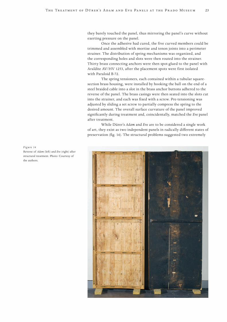
While Dürer’s Adam and Eve are to be considered a single work of art, they exist as two independent panels in radically different states of preservation (fig. 14). The structural problems suggested two extremely
F ig u re 14
Reverse of Adam (left) and Eve (right) after structural treatment. Photo: Courtesy of the authors.
24
PROOF 1 2 3 4 5 6
B i s a c c a a n d d e l a F u e n t e M a r t í n e z
different treatments, yet by employing the same aesthetic and mechani-cal principles, we were able to bring the two panels into balance as one work of art.
Note 1 Laponite RD is a synthetic inorganic colloidal clay powder. Water can be added to the
desired consistency so that moisture will be kept on the surface without penetrating into the wood.
Materials and Suppliers Araldite AV/HV 1253 and Araldite 2011 (AW 106/HV 953), Huntsman Advanced Materials,
10003 Woodloch Forest Drive, The Woodlands, TX 77380, USA. Distributed by Freeman Manufacturing and Supply Co., 1101 Moore Road, Avon, OH 44011, USA. http://freemansupply.com.
High-Tack fish glue, Lee Valley Tools Ltd., P.O. Box 1780, Ogdensburg, NY 13669, USA. P.O. Box 6295, Station J, Ottawa, ON K2A 1T4, Canada. www.leevalley.com.
25
PROOF 1 2 3 4 5 6
Abstract This paper presents the work done in the Florentine Opificio delle Pietre Dure
for the improvement of the conservation of paintings on wooden supports, start-ing in the beginning of the 1980s.
The introduction summarizes the main guidelines and the technical methods carried out in the recent past. The paper then presents case studies of important paintings that have undergone restoration in recent years. They are:
• Bronzino, Descent of Christ into Limbo, Santa Croce Museum, Florence: A new type of batten was proposed, with the same shape as the ancient ones, and inserted in a dovetail channel.
• Botticelli, Mourning of the Dead Christ, Poldi Pezzoli Museum, Milan: A new stretcher control system was applied without the original support being touched.
• Masaccio, a predella, Storia di San Giuliano, Horne Museum, Florence: The stretcher control system was applied with very few connection points, and the rear was closed with loose wooden elements.
• Antonello da Messina, Portrait of a Man, Palazzo Madama Museum, Turin: The flexible control system was not applied on the panel but was connected to the frame, modified to close the back of the painting.
• The Rosano Crucifix, Abbey of Santa Maria di Rosano, Rignano sull’Arno: The original construction system was reestablished, with a less invasive and more functional conservation treatment.
• Raphael, Madonna of the Goldfinch, Uffizi Gallery, Florence: Because of the ancient damage, a low-invasive technique was performed on the old cracks.
In the conclusion the paper points to the authors’ planned research for the future.
Introduction Painting restoration in Florence, including the conservation of wood
supports, has a long tradition. This situation may be adequately illus-trated by several examples from the history of restoration: in 1830 Pietro Rombergh applied the “cradling” technique derived from the French method—in fact, we know today that it may be ascribed to Jean Louis Hacquin—to Raphael’s Madonna del Baldacchino, thus contributing locally to the diffusion of what would later be mistakenly referred to as “Florentine cradling (parchettatura)” (Chiarini, Padovani, and Ciatti 1991).
The Conservation of Panel Painting Supports at the Opificio delle Pietre Dure: Experiences and Methodologies
Marco Ciatti and Ciro Castelli
26
PROOF 1 2 3 4 5 6
C i a t t i a n d C a s t e l l i
Throughout the second half of the nineteenth century, restor-ers of wooden supports are frequently mentioned working together with those treating the painted surfaces—for example, Giuseppe Tanagli, who, with Ettore Franchi, restored the Coronation of the Virgin by Lorenzo Monaco in 1867. Treatment of this altarpiece, now in the Uffizi, included repair of the large central lacuna, repair of several cracks by means of dovetail inserts, and application of three new battens housed in dovetail-shaped tracks (Ciatti and Frosinini 1998). A year before, in 1866, the Florentine Gallery painter-restorer Ulisse Forni documented in his Manuale del pittore restauratore a series of interventive techniques to be done with the aid of an expert in carpentry1 (Bonsanti and Ciatti 2004, 58–59). Among these we may already find the idea by which two discon-nected boards could be rejoined by inserting V-shaped wedges into spe-cifically carved-out channels.
During the twentieth century, first at the Restoration Laboratory at the Vecchia Posta in Florence and then at the Fortezza da Basso in Florence, operators were continuously striving for ways to refine meth-ods for intervention. For example, the system for using wedges to repair cracks was perfected, and new sliding crosspieces were devised, inserted into tracks formed by pairs of cleats, called nottole. The practice of flat-tening curved panels was abandoned according to new theories based on greater respect for the characteristics of the artwork and the apprecia-tion of signs of natural aging of the materials. The major personalities of this historic phase were in particular Otello Caprara, Renzo Turchi, and Gianni Marussich, who together with others, all of whom we recall with gratitude and affection, were called to face the tragic circumstances gen-erated by the 1966 flood.
Starting in the 1980s, after this phase of emergency was over-come, renewed research into ways to better understand the behavior of wood supports was undertaken at the Fortezza Laboratory—also thanks to collaboration with several research institutes and universities—aimed at gathering measurable, verifiable data on the various phenomena that take place. Following these studies, numerous fundamental changes were gradually introduced, which may be summed up as follows:
• introductionoflessinvasivemethodsofapplyingwedgesthroughnewways to create the channels that will house them, in a general context of recognizing the need to reduce invasiveness in all phases of the intervention;
• introductionofmethodstoapplybattens,withtheaimofobtainingelastic control of the eventual tendency to warp, paired with main-taining freedom of movement of the panel boards;
• forthinnedorfragilesupports,thesubstitutionofbattenswithframestructures, which function as the principal support; a frame structure connects to the panel through systems that guarantee both sliding capacity and elasticity;
• increasinglycloseinterconnectionbetweentherestorationandpreventive conservation phases, aiming at controlled reduced air exchange with the surrounding atmosphere to reduce fluctuations in relative humidity (RH) to gain greater stability;
• increasedrespectfortheoriginalcharacteristicsofconstruction,often involving the replacement of lost functionality of the original elements.
27
PROOF 1 2 3 4 5 6
Th e C o n s e r va t i o n o f Pa n e l Pa i n t i n g S u p p o r t s a t t h e O p i f i c i o d e l l e P i e t r e D u r e : E x p e r i e n c e s a n d M e t h o d o l o g i e s
These new operational guidelines materialized in many exam-ples of conservation and restoration interventions and were presented in an organic way for the first time in the volume Dipinti su tavola: La tecnica e la conservazione dei supporti, published in 1999. In a response to widespread requests, an English edition was published in 2006, thanks to the translation by Diane Kunzelman (Ciatti, Castelli, and Santacesaria 1999; 2006).
Since then, continuing research has also been put into practice in concrete work situations, as we consider these two elements inseparable and believe that they naturally proceed hand in hand. In summary, our methodological guidelines aim at furthering the following:
• evergreaterunderstandingoftechniquesofconstructionofwoodensupports and their behavior over time;
• increasinglyprecisemeasurementsofthephysicalbehaviorofpaint-ings, including application of 3-D techniques before, during, and after restoration operations;
• atendencytowardwhatisdefinedas“minimalintervention,”mean-ing the will to achieve desired conservation results with the least pos-sible invasiveness;
• realizationofanoverallrestorationprojectthatinvolvesboththework’s structural support system and its pictorial components;
• decisionmakingforrestorationthatissimultaneouslyintegratedwithpreventive conservation.
The Case Studies The case studies and the topic specific to each that will be presented here
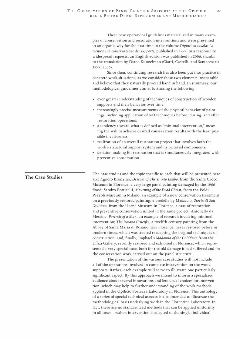
are: Agnolo Bronzino, Descent of Christ into Limbo, from the Santa Croce Museum in Florence, a very large panel painting damaged by the 1966 flood; Sandro Botticelli, Mourning of the Dead Christ, from the Poldi Pezzoli Museum in Milano, an example of a new conservation treatment on a previously restored painting; a predella by Masaccio, Storia di San Giuliano, from the Horne Museum in Florence, a case of restoration and preventive conservation united in the same project; Antonello da Messina, Portrait of a Man, an example of research involving minimal intervention; The Rosano Crucifix, a twelfth-century painting from the Abbey of Santa Maria di Rosano near Florence, never restored before in modern times, which was treated readapting the original techniques of construction; and, finally, Raphael’s Madonna of the Goldfinch from the Uffizi Gallery, recently restored and exhibited in Florence, which repre-sented a very special case, both for the old damage it had suffered and for the conservation work carried out on the panel structure.
The presentation of the various case studies will not include all of the operations involved in complete intervention on the wood supports. Rather, each example will serve to illustrate one particularly significant aspect. By this approach we intend to inform a specialized audience about several innovations and less usual choices for interven-tion, which may help to further understanding of the work methods applied in the Opificio Fortezza Laboratory in Florence. This anthology of a series of special technical aspects is also intended to illustrate the methodological basis underlying work in the Florentine Laboratory. In fact, there are no standardized methods that can be applied uniformly in all cases—rather, intervention is adapted to the single, individual
28
PROOF 1 2 3 4 5 6
C i a t t i a n d C a s t e l l i
characteristics of the specific work being treated. Both the actual tech-nical elements present in each work and the theoretical implications of these are important considerations.
Bronzino’s Descent of Christ into Limbo
For example, the large flood-damaged panel by Agnolo Bronzino, Descent of Christ into Limbo (fig. 1), was put back on exhibition in fall 2006, where it was presented together with eight other large panel paintings that had suffered damage from the same event (Ciatti, Frosinini, and Rossi Scarzanella 2006). After the flood, removal of battens was carried out in a storage site at the Limonaia, in which a high RH was maintained, for the purpose of avoiding as far as possible the negative effects of shrinkage of the wood. The state of conservation of the painting many years after the flood was, in any case, extremely serious. Much of the damage caused by the flood involved shrinkage of planks, splits, and separation between boards, and loss of cohesion of the ground—all of which combined to produce damage to the paint layers, mainly flaking.
The varying lengths of time the different parts of the painting remained under water, according to the height at which they were found, caused separation of the boards in the central and lower parts, as well as cupping of the planks.
The point we would like to emphasize in this case is the decision to restore the original control system, based on dovetail-shaped battens inserted into grooves. It was determined that this system was capable of
F ig u re 1
Agnolo Bronzino (Italian, 1503–1572), Descent
of Christ into Limbo, 1552. Oil on panel, 443 × 291 cm (174.4 × 114.6 in.). Museo dell’Opera di Santa Croce, Florence (on loan from the Gallerie Fiorentine, inv. 1890 n. 1580). The front and back of the painting after conserva-tion. Photos: Archivio dell’Opificio delle Pietre Dure, Florence.
29
PROOF 1 2 3 4 5 6
Th e C o n s e r va t i o n o f Pa n e l Pa i n t i n g S u p p o r t s a t t h e O p i f i c i o d e l l e P i e t r e D u r e : E x p e r i e n c e s a n d M e t h o d o l o g i e s
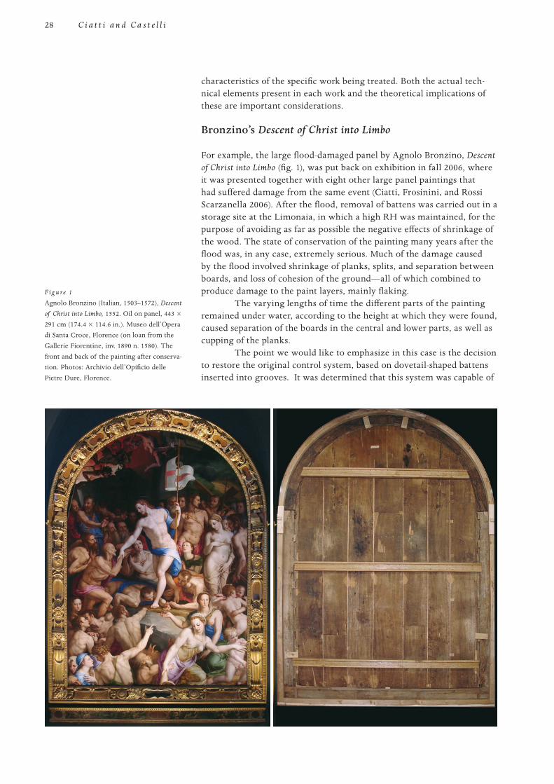
assuring the necessary control of a panel painting affected by separation of the boards and warp of the single planks only in the lower portion. In order to face the problem of movements of the panel in a more flexible way—and avoid their having negative repercussions on the paint layers—it was decided to modify the inner structure of the battens. This was accomplished by inserting a system able to guarantee elastic flexibility in them, through separation into three layers (fig. 2). The oblique side edges of the grooves that originally housed the crossbars were leveled, and the seat of the tract was rendered flat by integration with small pieces of old wood. The laminated battens were then mounted: the first layer inserted into the original groove on the support, the second and third connected to the first with screws and springs. In this way it was possible to regu-late the pressure of the single crossbar strips.
Operations were also planned to take into account the preven-tive conservation phase, by means of a box enclosure fitted onto the rear, designed to reduce the exchange of moisture with the surrounding atmo-sphere, thereby reducing the support’s tendency to move. It was thus possible to satisfy the needs of the painting for an elastic form of warp control and to safeguard the adhesion of the color.
After the frame was restored and assembled, the painting was placed in it, and the rear was closed with a panel. In the exhibition site, the pressure exerted by the springs was regulated according to the local RH. To better stabilize the RH level, Art Sorb was placed through an opening in the space between the panel closing the frame and the rear of the wood support.
Botticelli’s Mourning of the Dead Christ
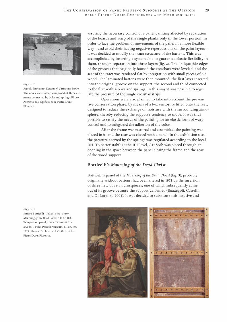
Botticelli’s panel of the Mourning of the Dead Christ (fig. 3), probably originally without battens, had been altered in 1951 by the insertion of three new dovetail crosspieces, one of which subsequently came out of its groove because the support deformed (Buzzegoli, Castelli, and Di Lorenzo 2004). It was decided to substitute this invasive and
F ig u re 2
Agnolo Bronzino, Descent of Christ into Limbo.
The new elastic batten composed of three ele-ments connected by bolts and springs. Photo: Archivio dell’Opificio delle Pietre Dure, Florence.
F ig u re 3
Sandro Botticelli (Italian, 1445–1510), Mourning of the Dead Christ, 1495–1500. Tempera on panel, 106 × 71 cm (41.7 × 28.0 in.). Poldi Pezzoli Museum, Milan, inv. 1558. Photos: Archivio dell’Opificio delle Pietre Dure, Florence.
30
PROOF 1 2 3 4 5 6
C i a t t i a n d C a s t e l l i
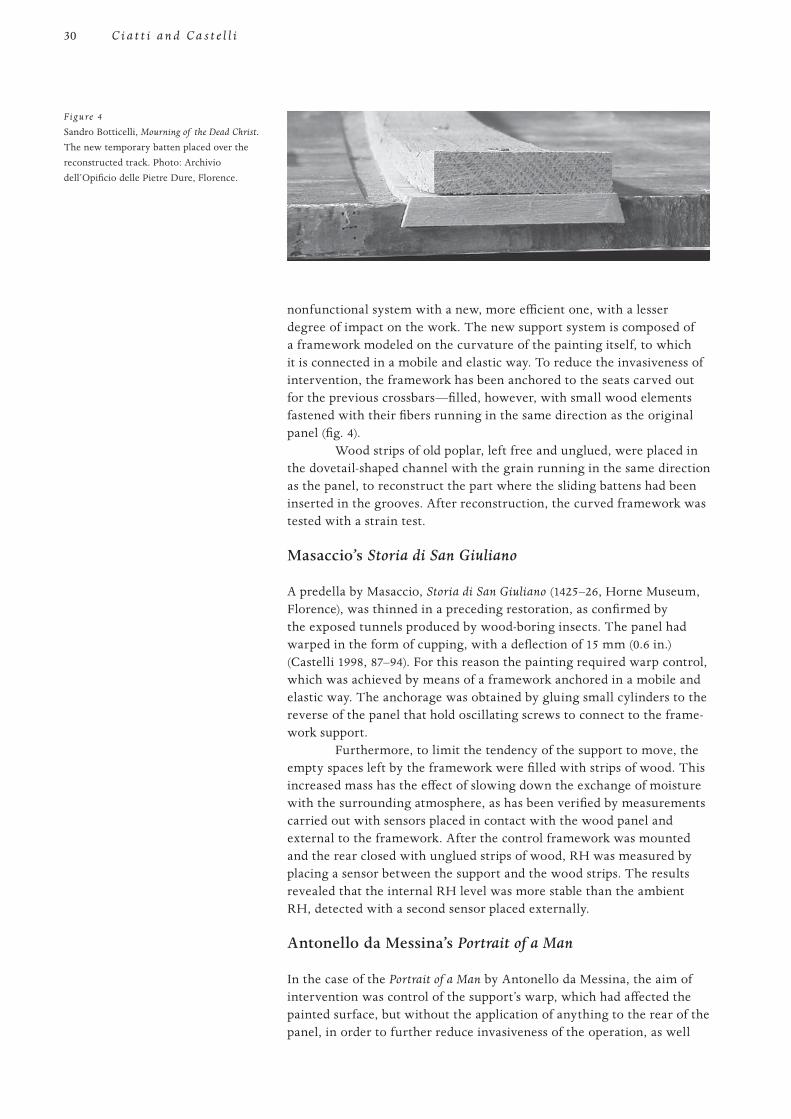
nonfunctional system with a new, more efficient one, with a lesser degree of impact on the work. The new support system is composed of a framework modeled on the curvature of the painting itself, to which it is connected in a mobile and elastic way. To reduce the invasiveness of intervention, the framework has been anchored to the seats carved out for the previous crossbars—filled, however, with small wood elements fastened with their fibers running in the same direction as the original panel (fig. 4).
Wood strips of old poplar, left free and unglued, were placed in the dovetail-shaped channel with the grain running in the same direction as the panel, to reconstruct the part where the sliding battens had been inserted in the grooves. After reconstruction, the curved framework was tested with a strain test.
Masaccio’s Storia di San Giuliano
A predella by Masaccio, Storia di San Giuliano (1425–26, Horne Museum, Florence), was thinned in a preceding restoration, as confirmed by the exposed tunnels produced by wood-boring insects. The panel had warped in the form of cupping, with a deflection of 15 mm (0.6 in.) (Castelli 1998, 87–94). For this reason the painting required warp control, which was achieved by means of a framework anchored in a mobile and elastic way. The anchorage was obtained by gluing small cylinders to the reverse of the panel that hold oscillating screws to connect to the frame-work support.
Furthermore, to limit the tendency of the support to move, the empty spaces left by the framework were filled with strips of wood. This increased mass has the effect of slowing down the exchange of moisture with the surrounding atmosphere, as has been verified by measurements carried out with sensors placed in contact with the wood panel and external to the framework. After the control framework was mounted and the rear closed with unglued strips of wood, RH was measured by placing a sensor between the support and the wood strips. The results revealed that the internal RH level was more stable than the ambient RH, detected with a second sensor placed externally.
Antonello da Messina’s Portrait of a Man
In the case of the Portrait of a Man by Antonello da Messina, the aim of intervention was control of the support’s warp, which had affected the painted surface, but without the application of anything to the rear of the panel, in order to further reduce invasiveness of the operation, as well
Figure 4
Sandro Botticelli, Mourning of the Dead Christ.
The new temporary batten placed over the reconstructed track. Photo: Archivio dell’Opificio delle Pietre Dure, Florence.
31
PROOF 1 2 3 4 5 6
Th e C o n s e r va t i o n o f Pa n e l Pa i n t i n g S u p p o r t s a t t h e O p i f i c i o d e l l e P i e t r e D u r e : E x p e r i e n c e s a n d M e t h o d o l o g i e s
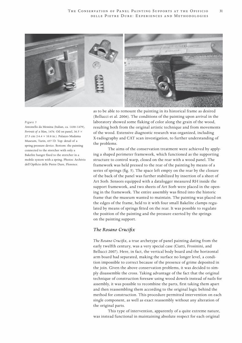
as to be able to remount the painting in its historical frame as desired (Bellucci et al. 2006). The conditions of the painting upon arrival in the laboratory showed some flaking of color along the grain of the wood, resulting both from the original artistic technique and from movements of the wood. Extensive diagnostic research was organized, including X-radiography and CAT scan investigation, to further understanding of the problems.
The aims of the conservation treatment were achieved by apply-ing a shaped perimeter framework, which functioned as the supporting structure to control warp, closed on the rear with a wood panel. The framework was held pressed to the rear of the painting by means of a series of springs (fig. 5). The space left empty on the rear by the closure of the back of the panel was further stabilized by insertion of a sheet of Art Sorb. Sensors equipped with a datalogger measured RH inside the support framework, and two sheets of Art Sorb were placed in the open-ing in the framework. The entire assembly was fitted into the historic frame that the museum wanted to maintain. The painting was placed on the edges of the frame, held to it with four small Bakelite clamps regu-lated by means of springs fitted on the rear. It was possible to regulate the position of the painting and the pressure exerted by the springs on the painting support.
The Rosano Crucifix
The Rosano Crucifix, a true archetype of panel painting dating from the early twelfth century, was a very special case (Ciatti, Frosinini, and Bellucci 2007). Here, in fact, the vertical body board and the horizontal arm board had separated, making the surface no longer level, a condi-tion impossible to correct because of the presence of grime deposited in the join. Given the above conservation problems, it was decided to sim-ply disassemble the cross. Taking advantage of the fact that the original technique of construction foresaw using wood dowels instead of nails for assembly, it was possible to recombine the parts, first taking them apart and then reassembling them according to the original logic behind the method for construction. This procedure permitted intervention on each single component, as well as exact reassembly without any alteration of the original parts.
This type of intervention, apparently of a quite extreme nature, was instead functional in maintaining absolute respect for each original
Figure 5
Antonello da Messina (Italian, ca. 1430–1479), Portrait of a Man, 1476. Oil on panel, 36.5 × 27.5 cm (14.4 × 10.8 in.). Palazzo Madama Museum, Turin, 437/D. Top: detail of a spring pressure device. Bottom: the painting connected to the stretcher with only a Bakelite hanger fixed to the stretcher in a mobile system with a spring. Photos: Archivio dell’Opificio delle Pietre Dure, Florence.
32
PROOF 1 2 3 4 5 6
C i a t t i a n d C a s t e l l i
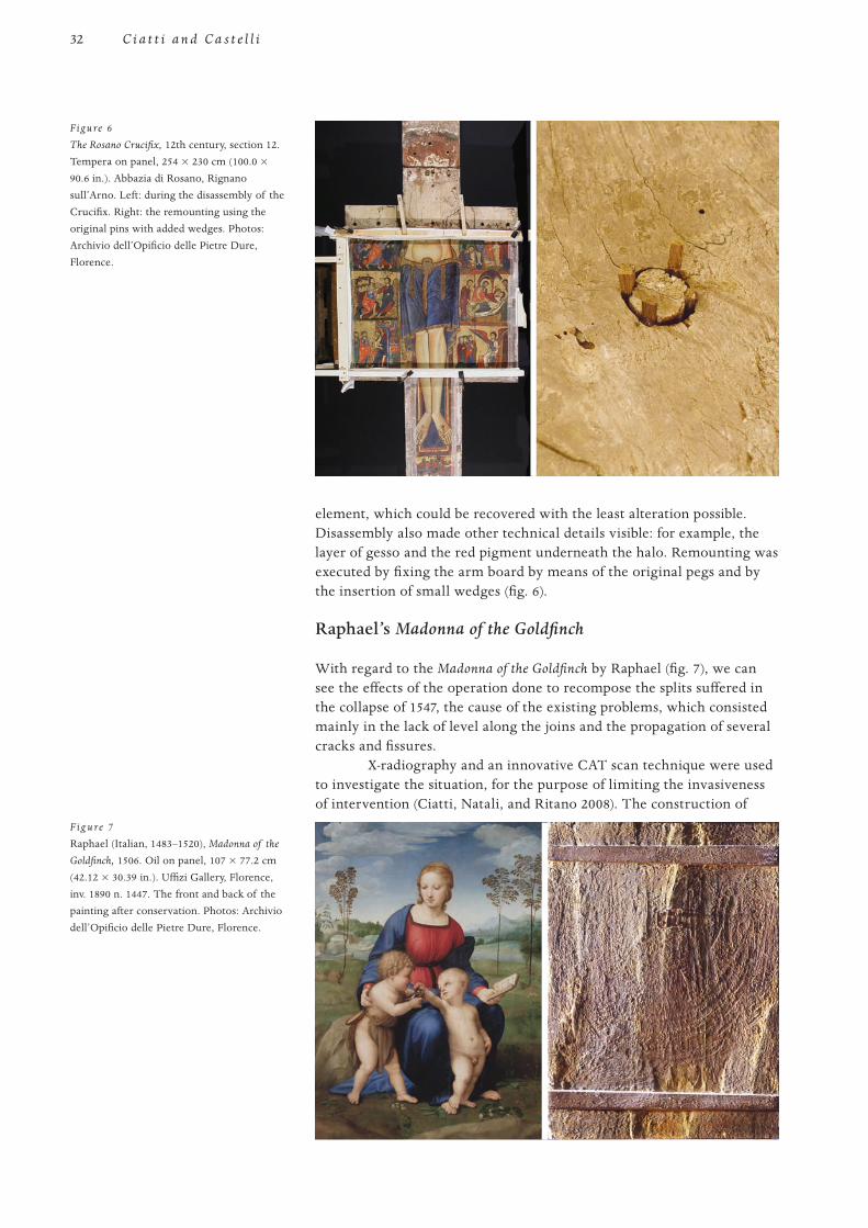
element, which could be recovered with the least alteration possible. Disassembly also made other technical details visible: for example, the layer of gesso and the red pigment underneath the halo. Remounting was executed by fixing the arm board by means of the original pegs and by the insertion of small wedges (fig. 6).
Raphael’s Madonna of the Goldfinch
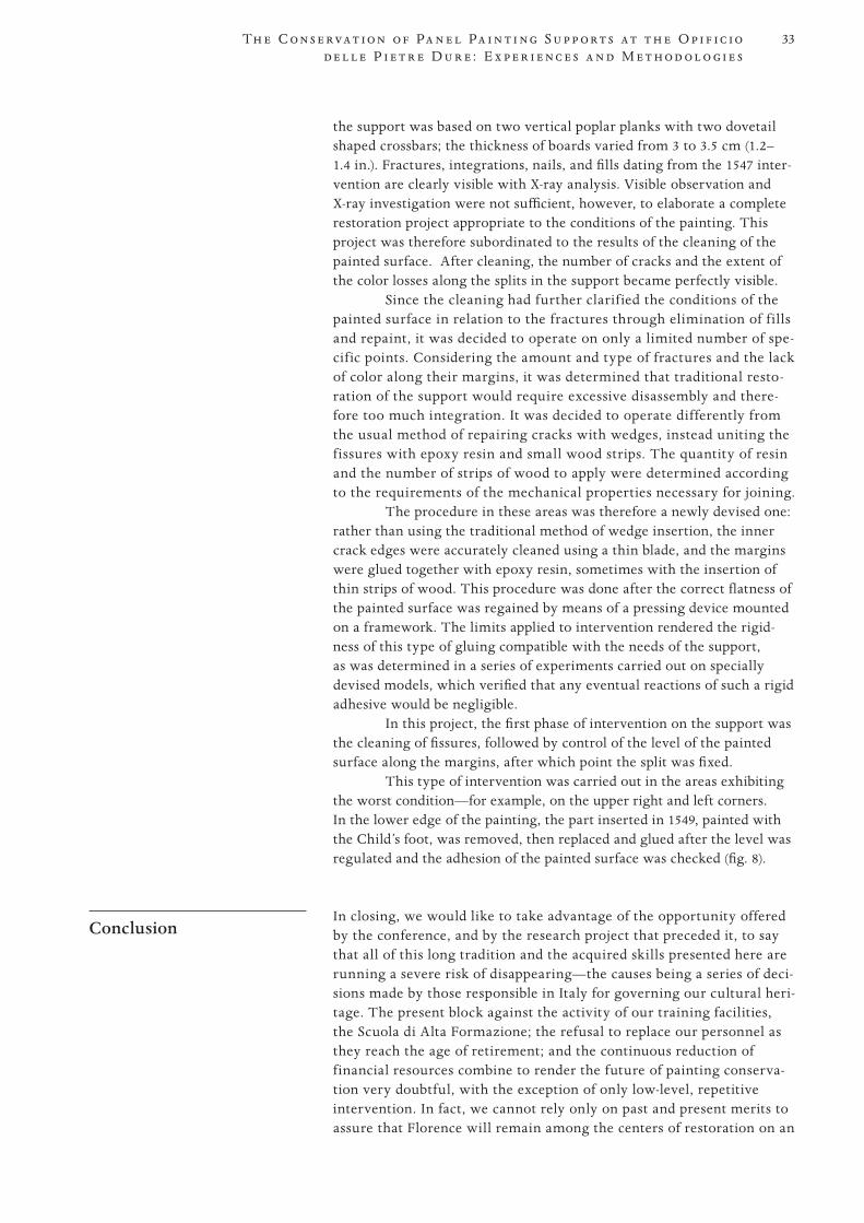
With regard to the Madonna of the Goldfinch by Raphael (fig. 7), we can see the effects of the operation done to recompose the splits suffered in the collapse of 1547, the cause of the existing problems, which consisted mainly in the lack of level along the joins and the propagation of several cracks and fissures.
X-radiography and an innovative CAT scan technique were used to investigate the situation, for the purpose of limiting the invasiveness of intervention (Ciatti, Natali, and Ritano 2008). The construction of
Figure 6
The Rosano Crucifix, 12th century, section 12. Tempera on panel, 254 × 230 cm (100.0 × 90.6 in.). Abbazia di Rosano, Rignano sull’Arno. Left: during the disassembly of the Crucifix. Right: the remounting using the original pins with added wedges. Photos: Archivio dell’Opificio delle Pietre Dure, Florence.
F ig u re 7
Raphael (Italian, 1483–1520), Madonna of the
Goldfinch, 1506. Oil on panel, 107 × 77.2 cm (42.12 × 30.39 in.). Uffizi Gallery, Florence, inv. 1890 n. 1447. The front and back of the painting after conservation. Photos: Archivio dell’Opificio delle Pietre Dure, Florence.
33
PROOF 1 2 3 4 5 6
Th e C o n s e r va t i o n o f Pa n e l Pa i n t i n g S u p p o r t s a t t h e O p i f i c i o d e l l e P i e t r e D u r e : E x p e r i e n c e s a n d M e t h o d o l o g i e s
the support was based on two vertical poplar planks with two dovetail shaped crossbars; the thickness of boards varied from 3 to 3.5 cm (1.2–1.4 in.). Fractures, integrations, nails, and fills dating from the 1547 inter-vention are clearly visible with X-ray analysis. Visible observation and X-ray investigation were not sufficient, however, to elaborate a complete restoration project appropriate to the conditions of the painting. This project was therefore subordinated to the results of the cleaning of the painted surface. After cleaning, the number of cracks and the extent of the color losses along the splits in the support became perfectly visible.
Since the cleaning had further clarif ied the conditions of the painted surface in relation to the fractures through elimination of f ills and repaint, it was decided to operate on only a limited number of spe-cif ic points. Considering the amount and type of fractures and the lack of color along their margins, it was determined that traditional resto-ration of the support would require excessive disassembly and there-fore too much integration. It was decided to operate differently from the usual method of repairing cracks with wedges, instead uniting the f issures with epoxy resin and small wood strips. The quantity of resin and the number of strips of wood to apply were determined according to the requirements of the mechanical properties necessary for joining.
The procedure in these areas was therefore a newly devised one: rather than using the traditional method of wedge insertion, the inner crack edges were accurately cleaned using a thin blade, and the margins were glued together with epoxy resin, sometimes with the insertion of thin strips of wood. This procedure was done after the correct flatness of the painted surface was regained by means of a pressing device mounted on a framework. The limits applied to intervention rendered the rigid-ness of this type of gluing compatible with the needs of the support, as was determined in a series of experiments carried out on specially devised models, which verified that any eventual reactions of such a rigid adhesive would be negligible.
In this project, the first phase of intervention on the support was the cleaning of fissures, followed by control of the level of the painted surface along the margins, after which point the split was fixed.
This type of intervention was carried out in the areas exhibiting the worst condition—for example, on the upper right and left corners. In the lower edge of the painting, the part inserted in 1549, painted with the Child’s foot, was removed, then replaced and glued after the level was regulated and the adhesion of the painted surface was checked (fig. 8).
Conclusion In closing, we would like to take advantage of the opportunity offered
by the conference, and by the research project that preceded it, to say that all of this long tradition and the acquired skills presented here are running a severe risk of disappearing—the causes being a series of deci-sions made by those responsible in Italy for governing our cultural heri-tage. The present block against the activity of our training facilities, the Scuola di Alta Formazione; the refusal to replace our personnel as they reach the age of retirement; and the continuous reduction of financial resources combine to render the future of painting conserva-tion very doubtful, with the exception of only low-level, repetitive intervention. In fact, we cannot rely only on past and present merits to assure that Florence will remain among the centers of restoration on an
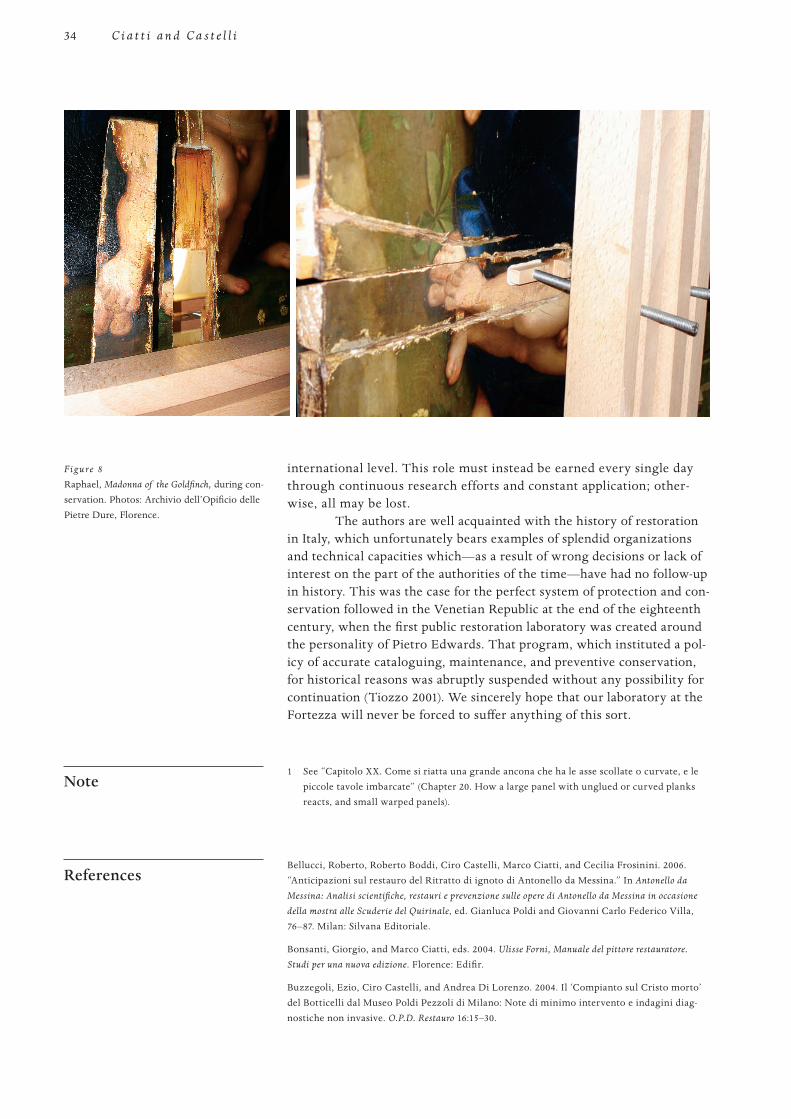
34
PROOF 1 2 3 4 5 6
C i a t t i a n d C a s t e l l i
international level. This role must instead be earned every single day through continuous research efforts and constant application; other-wise, all may be lost.
The authors are well acquainted with the history of restoration in Italy, which unfortunately bears examples of splendid organizations and technical capacities which—as a result of wrong decisions or lack of interest on the part of the authorities of the time—have had no follow-up in history. This was the case for the perfect system of protection and con-servation followed in the Venetian Republic at the end of the eighteenth century, when the first public restoration laboratory was created around the personality of Pietro Edwards. That program, which instituted a pol-icy of accurate cataloguing, maintenance, and preventive conservation, for historical reasons was abruptly suspended without any possibility for continuation (Tiozzo 2001). We sincerely hope that our laboratory at the Fortezza will never be forced to suffer anything of this sort.
Note 1 See “Capitolo XX. Come si riatta una grande ancona che ha le asse scollate o curvate, e le
piccole tavole imbarcate” (Chapter 20. How a large panel with unglued or curved planks reacts, and small warped panels).
References Bellucci, Roberto, Roberto Boddi, Ciro Castelli, Marco Ciatti, and Cecilia Frosinini. 2006.
“Anticipazioni sul restauro del Ritratto di ignoto di Antonello da Messina.” In Antonello da
Messina: Analisi scientifiche, restauri e prevenzione sulle opere di Antonello da Messina in occasione
della mostra alle Scuderie del Quirinale, ed. Gianluca Poldi and Giovanni Carlo Federico Villa, 76–87. Milan: Silvana Editoriale.
Bonsanti, Giorgio, and Marco Ciatti, eds. 2004. Ulisse Forni, Manuale del pittore restauratore.
Studi per una nuova edizione. Florence: Edifir.
Buzzegoli, Ezio, Ciro Castelli, and Andrea Di Lorenzo. 2004. Il ‘Compianto sul Cristo morto’ del Botticelli dal Museo Poldi Pezzoli di Milano: Note di minimo intervento e indagini diag-nostiche non invasive. O.P.D. Restauro 16:15–30.
Figure 8
Raphael, Madonna of the Goldfinch, during con-servation. Photos: Archivio dell’Opificio delle Pietre Dure, Florence.
35
PROOF 1 2 3 4 5 6
Th e C o n s e r va t i o n o f Pa n e l Pa i n t i n g S u p p o r t s a t t h e O p i f i c i o d e l l e P i e t r e D u r e : E x p e r i e n c e s a n d M e t h o d o l o g i e s
Castelli, Ciro. 1998. Metodo di riduzione dei movimenti dei supporti lignei dipinti. O.P.D.
Restauro 10:87–94.
Chiarini, Marco, Serena Padovani, and Marco Ciatti, eds. 1991. Raffaello a Pitti. ‘La Madonna del
Baldacchino.’ Storia e restauro. Florence: Centro Di.
Ciatti, Marco, Ciro Castelli, and Andrea Santacesaria, eds. 1999. Dipinti su tavola: La tecnica e la
conservazione dei supporti. Florence: Edifir.
. eds. 2006. Panel painting: Technique and Conservation of Wood Supports. Florence: Edifir.
Ciatti, Marco, and Cecilia Frosinini, eds. 1998. Lorenzo Monaco. Tecnica e restauro.
L’ Incoronazione della Vergine degli Uffizi e l’Annunciazione di Santa Trinità di Firenze. Florence: Edifir.
Ciatti, Marco, Cecilia Frosinini, and Roberto Bellucci, eds. 2007. La Croce dipinta dell’abbazia di
Rosano. Visibile e invisibile. Studio e restauro per la comprensione. Florence: Edifir.
Ciatti, Marco, Cecilia Frosinini, and Chiara Rossi Scarzanella, eds. 2006. Angeli, santi e demoni:
Otto capolavori restaurati. Santa Croce quaranta anni dopo (1966–2006). Florence: Edifir.
Ciatti, Marco, Antonio Natali, and Patrizia Ritano, eds. 2008. Raffaello: La rivelazione del colore.
Il restauro della Madonna del Cardellino della Galleria degli Uffizi. Florence: Edifir.
Tiozzo, Vanni, ed. 2001. Dal decalogo Edwards alla Carta del Restauro. Pratiche e principi del
restauro dei dipinti. Padua: Il Prato.
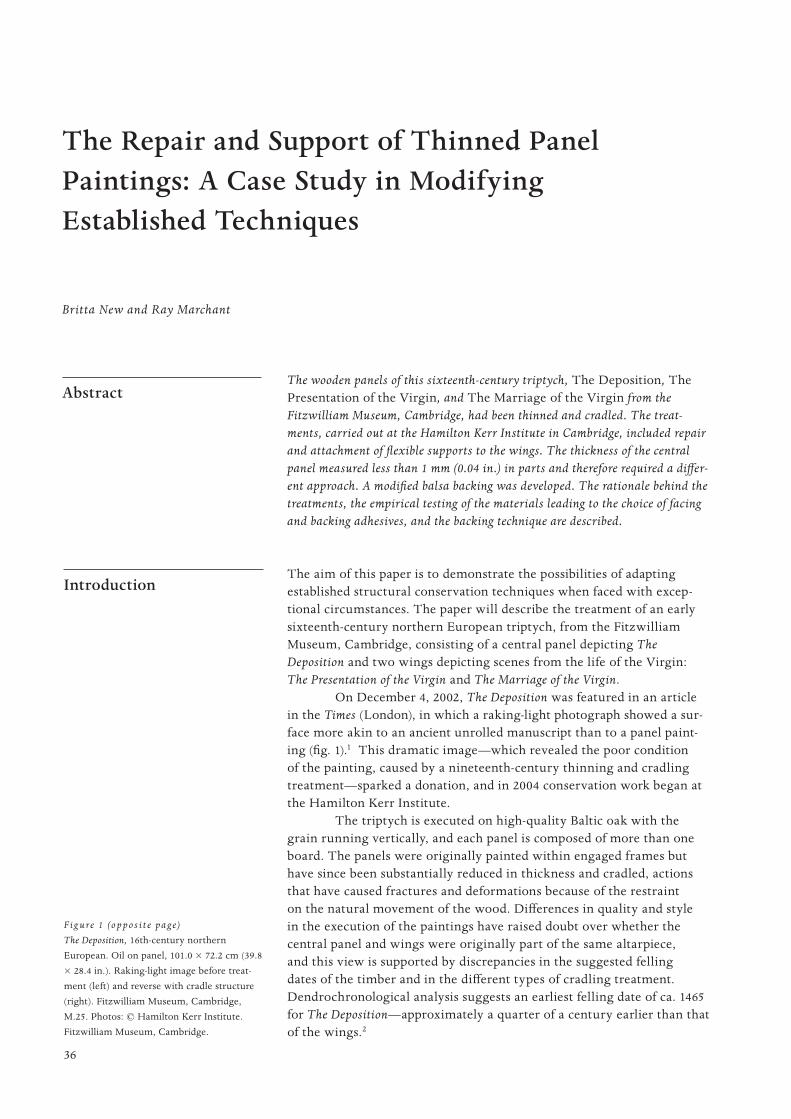
36
PROOF 1 2 3 4 5 6
The Repair and Support of Thinned Panel Paintings: A Case Study in Modifying Established Techniques
The wooden panels of this sixteenth-century triptych, The Deposition, The Presentation of the Virgin, and The Marriage of the Virgin from the Fitzwilliam Museum, Cambridge, had been thinned and cradled. The treat-ments, carried out at the Hamilton Kerr Institute in Cambridge, included repair and attachment of flexible supports to the wings. The thickness of the central panel measured less than 1 mm (0.04 in.) in parts and therefore required a differ-ent approach. A modified balsa backing was developed. The rationale behind the treatments, the empirical testing of the materials leading to the choice of facing and backing adhesives, and the backing technique are described.
Introduction The aim of this paper is to demonstrate the possibilities of adapting
established structural conservation techniques when faced with excep-tional circumstances. The paper will describe the treatment of an early sixteenth-century northern European triptych, from the Fitzwilliam Museum, Cambridge, consisting of a central panel depicting The Deposition and two wings depicting scenes from the life of the Virgin: The Presentation of the Virgin and The Marriage of the Virgin.
On December 4, 2002, The Deposition was featured in an article in the Times (London), in which a raking-light photograph showed a sur-face more akin to an ancient unrolled manuscript than to a panel paint-ing (fig. 1).1 This dramatic image—which revealed the poor condition of the painting, caused by a nineteenth-century thinning and cradling treatment—sparked a donation, and in 2004 conservation work began at the Hamilton Kerr Institute.
The triptych is executed on high-quality Baltic oak with the grain running vertically, and each panel is composed of more than one board. The panels were originally painted within engaged frames but have since been substantially reduced in thickness and cradled, actions that have caused fractures and deformations because of the restraint on the natural movement of the wood. Differences in quality and style in the execution of the paintings have raised doubt over whether the central panel and wings were originally part of the same altarpiece, and this view is supported by discrepancies in the suggested felling dates of the timber and in the different types of cradling treatment. Dendrochronological analysis suggests an earliest felling date of ca. 1465 for The Deposition—approximately a quarter of a century earlier than that of the wings.2
Abstract
Britta New and Ray Marchant
F ig u re 1 (o p p o s i t e p a g e)
The Deposition, 16th-century northern European. Oil on panel, 101.0 × 72.2 cm (39.8 × 28.4 in.). Raking-light image before treat-ment (left) and reverse with cradle structure (right). Fitzwilliam Museum, Cambridge, M.25. Photos: © Hamilton Kerr Institute. Fitzwilliam Museum, Cambridge.
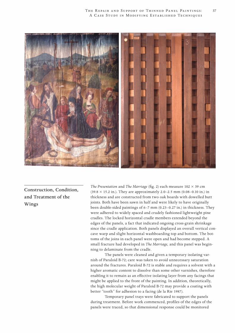
37
PROOF 1 2 3 4 5 6
Th e R e pa i r a n d S u p p o r t o f Th i n n e d Pa n e l Pa i n t i n g s : A C a s e S t u d y i n M o d i f y i n g E s t a b l i s h e d Te c h n i q u e s
Construction, Condition, and Treatment of the Wings
The Presentation and The Marriage (fig. 2) each measure 102 × 39 cm (39.8 × 15.2 in.). They are approximately 2.0–2.5 mm (0.08–0.10 in.) in thickness and are constructed from two oak boards with dowelled butt joints. Both have been sawn in half and were likely to have originally been double-sided paintings of 6–7 mm (0.23–0.27 in.) in thickness. They were adhered to widely spaced and crudely fashioned lightweight pine cradles. The locked horizontal cradle members extended beyond the edges of the panels, a fact that indicated ongoing cross-grain shrinkage since the cradle application. Both panels displayed an overall vertical con-cave warp and slight horizontal washboarding top and bottom. The bot-toms of the joins in each panel were open and had become stepped. A small fracture had developed in The Marriage, and this panel was begin-ning to delaminate from the cradle.
The panels were cleaned and given a temporary isolating var-nish of Paraloid B-72; care was taken to avoid unnecessary saturation around the fractures. Paraloid B-72 is stable and requires a solvent with a higher aromatic content to dissolve than some other varnishes, therefore enabling it to remain as an effective isolating layer from any facings that might be applied to the front of the painting. In addition, theoretically, the high molecular weight of Paraloid B-72 may provide a coating with better “tooth” for adhesion to a facing (de la Rie 1987).
Temporary panel trays were fabricated to support the panels during treatment. Before work commenced, profiles of the edges of the panels were traced, so that dimensional response could be monitored
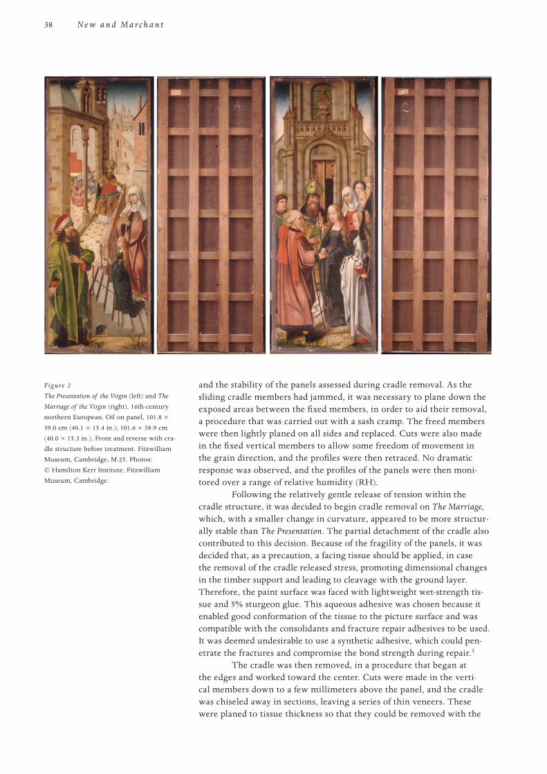
38
PROOF 1 2 3 4 5 6
N e w a n d M a r c h a n t
and the stability of the panels assessed during cradle removal. As the sliding cradle members had jammed, it was necessary to plane down the exposed areas between the fixed members, in order to aid their removal, a procedure that was carried out with a sash cramp. The freed members were then lightly planed on all sides and replaced. Cuts were also made in the fixed vertical members to allow some freedom of movement in the grain direction, and the profiles were then retraced. No dramatic response was observed, and the profiles of the panels were then moni-tored over a range of relative humidity (RH).
Following the relatively gentle release of tension within the cradle structure, it was decided to begin cradle removal on The Marriage, which, with a smaller change in curvature, appeared to be more structur-ally stable than The Presentation. The partial detachment of the cradle also contributed to this decision. Because of the fragility of the panels, it was decided that, as a precaution, a facing tissue should be applied, in case the removal of the cradle released stress, promoting dimensional changes in the timber support and leading to cleavage with the ground layer. Therefore, the paint surface was faced with lightweight wet-strength tis-sue and 5% sturgeon glue. This aqueous adhesive was chosen because it enabled good conformation of the tissue to the picture surface and was compatible with the consolidants and fracture repair adhesives to be used. It was deemed undesirable to use a synthetic adhesive, which could pen-etrate the fractures and compromise the bond strength during repair.3
The cradle was then removed, in a procedure that began at the edges and worked toward the center. Cuts were made in the verti-cal members down to a few millimeters above the panel, and the cradle was chiseled away in sections, leaving a series of thin veneers. These were planed to tissue thickness so that they could be removed with the
Figure 2
The Presentation of the Virgin (left) and The
Marriage of the Virgin (right), 16th-century northern European. Oil on panel, 101.8 × 39.0 cm (40.1 × 15.4 in.); 101.6 × 38.9 cm (40.0 × 15.3 in.). Front and reverse with cra-dle structure before treatment. Fitzwilliam Museum, Cambridge, M.25. Photos: © Hamilton Kerr Institute. Fitzwilliam Museum, Cambridge.
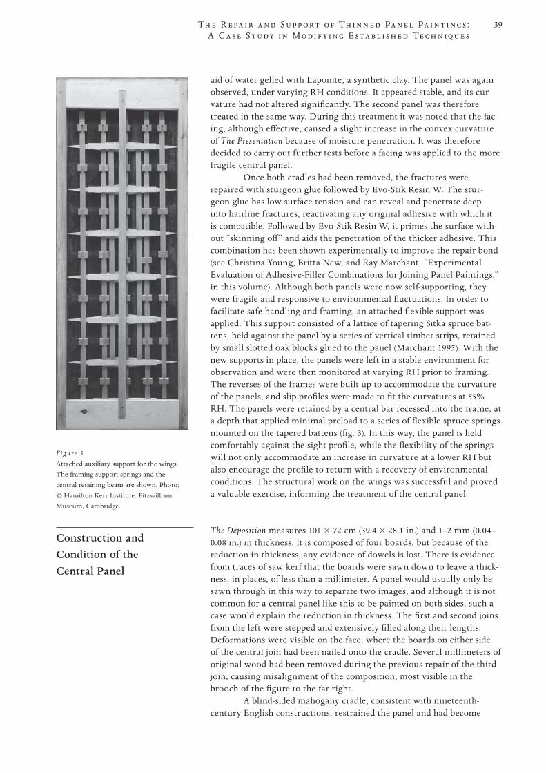
39
PROOF 1 2 3 4 5 6
Th e R e pa i r a n d S u p p o r t o f Th i n n e d Pa n e l Pa i n t i n g s : A C a s e S t u d y i n M o d i f y i n g E s t a b l i s h e d Te c h n i q u e s
aid of water gelled with Laponite, a synthetic clay. The panel was again observed, under varying RH conditions. It appeared stable, and its cur-vature had not altered significantly. The second panel was therefore treated in the same way. During this treatment it was noted that the fac-ing, although effective, caused a slight increase in the convex curvature of The Presentation because of moisture penetration. It was therefore decided to carry out further tests before a facing was applied to the more fragile central panel.
Once both cradles had been removed, the fractures were repaired with sturgeon glue followed by Evo-Stik Resin W. The stur-geon glue has low surface tension and can reveal and penetrate deep into hairline fractures, reactivating any original adhesive with which it is compatible. Followed by Evo-Stik Resin W, it primes the surface with-out “skinning off” and aids the penetration of the thicker adhesive. This combination has been shown experimentally to improve the repair bond (see Christina Young, Britta New, and Ray Marchant, “Experimental Evaluation of Adhesive-Filler Combinations for Joining Panel Paintings,” in this volume). Although both panels were now self-supporting, they were fragile and responsive to environmental fluctuations. In order to facilitate safe handling and framing, an attached flexible support was applied. This support consisted of a lattice of tapering Sitka spruce bat-tens, held against the panel by a series of vertical timber strips, retained by small slotted oak blocks glued to the panel (Marchant 1995). With the new supports in place, the panels were left in a stable environment for observation and were then monitored at varying RH prior to framing. The reverses of the frames were built up to accommodate the curvature of the panels, and slip profiles were made to fit the curvatures at 55% RH. The panels were retained by a central bar recessed into the frame, at a depth that applied minimal preload to a series of flexible spruce springs mounted on the tapered battens (fig. 3). In this way, the panel is held comfortably against the sight profile, while the flexibility of the springs will not only accommodate an increase in curvature at a lower RH but also encourage the profile to return with a recovery of environmental conditions. The structural work on the wings was successful and proved a valuable exercise, informing the treatment of the central panel.
Construction and Condition of the Central Panel
The Deposition measures 101 × 72 cm (39.4 × 28.1 in.) and 1–2 mm (0.04–0.08 in.) in thickness. It is composed of four boards, but because of the reduction in thickness, any evidence of dowels is lost. There is evidence from traces of saw kerf that the boards were sawn down to leave a thick-ness, in places, of less than a millimeter. A panel would usually only be sawn through in this way to separate two images, and although it is not common for a central panel like this to be painted on both sides, such a case would explain the reduction in thickness. The first and second joins from the left were stepped and extensively filled along their lengths. Deformations were visible on the face, where the boards on either side of the central join had been nailed onto the cradle. Several millimeters of original wood had been removed during the previous repair of the third join, causing misalignment of the composition, most visible in the brooch of the figure to the far right.
A blind-sided mahogany cradle, consistent with nineteenth-century English constructions, restrained the panel and had become
F ig u re 3
Attached auxiliary support for the wings. The framing support springs and the central retaining beam are shown. Photo: © Hamilton Kerr Institute. Fitzwilliam Museum, Cambridge.
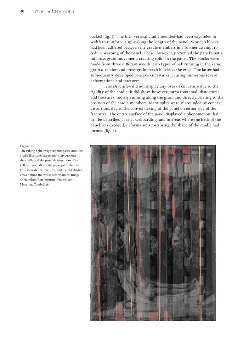
40
PROOF 1 2 3 4 5 6
N e w a n d M a r c h a n t
locked (fig. 1). The fifth vertical cradle member had been expanded in width to reinforce a split along the length of the panel. Wooden blocks had been adhered between the cradle members in a further attempt to reduce warping of the panel. These, however, prevented the panel’s natu-ral cross-grain movement, creating splits in the panel. The blocks were made from three different woods: two types of oak running in the same grain direction and cross-grain beech blocks at the ends. The latter had subsequently developed concave curvatures, causing numerous severe deformations and fractures.
The Deposition did not display any overall curvature due to the rigidity of the cradle. It did show, however, numerous small distortions and fractures, mostly running along the grain and directly relating to the position of the cradle members. Many splits were surrounded by concave distortions due to the convex flexing of the panel on either side of the fractures. The entire surface of the panel displayed a phenomenon that can be described as checkerboarding, and in areas where the back of the panel was exposed, deformations mirroring the shape of the cradle had formed (fig. 4).
F ig u re 4
The raking-light image superimposed onto the cradle illustrates the relationship between the cradle and the panel deformations. The yellow lines indicate the panel joins, the red lines indicate the fractures, and the red shaded areas outline the worst deformations. Image: © Hamilton Kerr Institute. Fitzwilliam Museum, Cambridge.
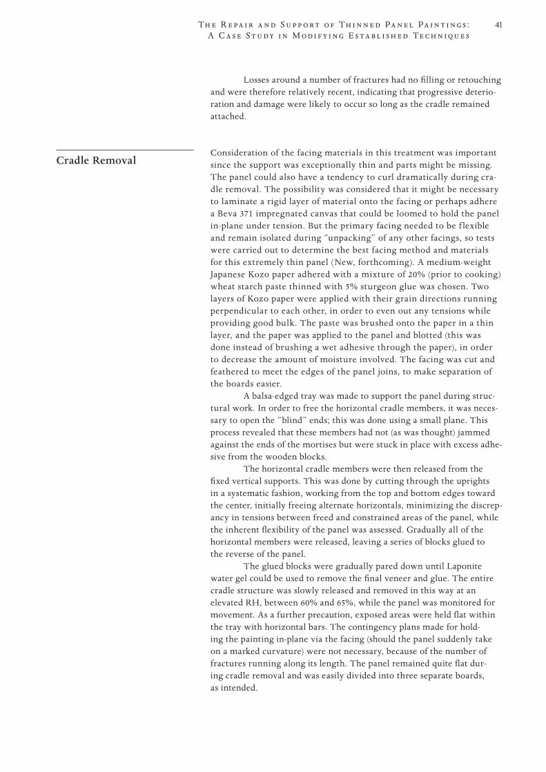
41
PROOF 1 2 3 4 5 6
Th e R e pa i r a n d S u p p o r t o f Th i n n e d Pa n e l Pa i n t i n g s : A C a s e S t u d y i n M o d i f y i n g E s t a b l i s h e d Te c h n i q u e s
Losses around a number of fractures had no filling or retouching and were therefore relatively recent, indicating that progressive deterio-ration and damage were likely to occur so long as the cradle remained attached.
Cradle Removal Consideration of the facing materials in this treatment was important
since the support was exceptionally thin and parts might be missing. The panel could also have a tendency to curl dramatically during cra-dle removal. The possibility was considered that it might be necessary to laminate a rigid layer of material onto the facing or perhaps adhere a Beva 371 impregnated canvas that could be loomed to hold the panel in-plane under tension. But the primary facing needed to be f lexible and remain isolated during “unpacking” of any other facings, so tests were carried out to determine the best facing method and materials for this extremely thin panel (New, forthcoming). A medium-weight Japanese Kozo paper adhered with a mixture of 20% (prior to cooking) wheat starch paste thinned with 5% sturgeon glue was chosen. Two layers of Kozo paper were applied with their grain directions running perpendicular to each other, in order to even out any tensions while providing good bulk. The paste was brushed onto the paper in a thin layer, and the paper was applied to the panel and blotted (this was done instead of brushing a wet adhesive through the paper), in order to decrease the amount of moisture involved. The facing was cut and feathered to meet the edges of the panel joins, to make separation of the boards easier.
A balsa-edged tray was made to support the panel during struc-tural work. In order to free the horizontal cradle members, it was neces-sary to open the “blind” ends; this was done using a small plane. This process revealed that these members had not (as was thought) jammed against the ends of the mortises but were stuck in place with excess adhe-sive from the wooden blocks.
The horizontal cradle members were then released from the fixed vertical supports. This was done by cutting through the uprights in a systematic fashion, working from the top and bottom edges toward the center, initially freeing alternate horizontals, minimizing the discrep-ancy in tensions between freed and constrained areas of the panel, while the inherent flexibility of the panel was assessed. Gradually all of the horizontal members were released, leaving a series of blocks glued to the reverse of the panel.
The glued blocks were gradually pared down until Laponite water gel could be used to remove the final veneer and glue. The entire cradle structure was slowly released and removed in this way at an elevated RH, between 60% and 65%, while the panel was monitored for movement. As a further precaution, exposed areas were held flat within the tray with horizontal bars. The contingency plans made for hold-ing the painting in-plane via the facing (should the panel suddenly take on a marked curvature) were not necessary, because of the number of fractures running along its length. The panel remained quite flat dur-ing cradle removal and was easily divided into three separate boards, as intended.
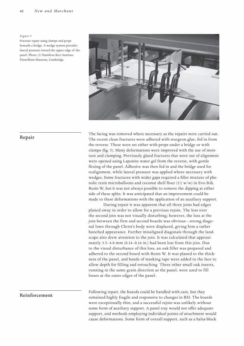
42
PROOF 1 2 3 4 5 6
N e w a n d M a r c h a n t
Repair The facing was removed where necessary as the repairs were carried out.
The recent clean fractures were adhered with sturgeon glue, fed in from the reverse. These were set either with props under a bridge or with clamps (fig. 5). Many deformations were improved with the use of mois-ture and clamping. Previously glued fractures that were out of alignment were opened using Laponite water gel from the reverse, with gentle flexing of the panel. Adhesive was then fed in and the bridge used for realignment, while lateral pressure was applied where necessary with wedges. Some fractures with wider gaps required a filler mixture of phe-nolic resin microballoons and coconut shell flour (1:1 w/w) in Evo-Stik Resin W, but it was not always possible to remove the dipping at either side of these splits. It was anticipated that an improvement could be made to these deformations with the application of an auxiliary support.
During repair it was apparent that all three joins had edges planed away in order to allow for a previous rejoin. The loss over the second join was not visually disturbing; however, the loss at the join between the first and second boards was obvious—strong diago-nal lines through Christ’s body were displaced, giving him a rather hunched appearance. Further misaligned diagonals through the land-scape also drew attention to the join. It was calculated that approxi-mately 3.5–4.0 mm (0.14–0.16 in.) had been lost from this join. Due to the visual disturbance of this loss, an oak fillet was prepared and adhered to the second board with Resin W. It was planed to the thick-ness of the panel, and bands of masking tape were added to the face to allow depth for filling and retouching. Three other small oak inserts, running in the same grain direction as the panel, were used to fill losses at the outer edges of the panel.
Reinforcement Following repair, the boards could be handled with care, but they
remained highly fragile and responsive to changes in RH. The boards were exceptionally thin, and a successful rejoin was unlikely without some form of auxiliary support. A panel tray would not offer adequate support, and methods employing individual points of attachment would cause deformations. Some form of overall support, such as a balsa-block
Figure 5
Fracture repair using clamps and props beneath a bridge. A wedge system provides lateral pressure toward the upper edge of the panel. Photo: © Hamilton Kerr Institute. Fitzwilliam Museum, Cambridge.
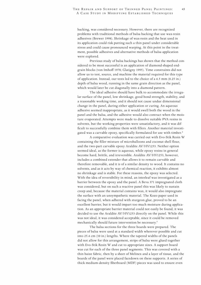
43
PROOF 1 2 3 4 5 6
Th e R e pa i r a n d S u p p o r t o f Th i n n e d Pa n e l Pa i n t i n g s : A C a s e S t u d y i n M o d i f y i n g E s t a b l i s h e d Te c h n i q u e s
backing, was considered necessary. However, there are recognized problems with traditional methods of balsa backing that use wax-resin adhesives (Brewer 1998). Shrinkage of wax-resin and the heat used in its application could risk putting such a thin panel under considerable stress and could cause pronounced warping. At this point in the treat-ment, possible adhesives and alternative methods of balsa application were explored.
Previous study of balsa backings has shown that the method con-sidered to be most successful is an application of diamond-shaped end-grain blocks (von Imhoff 1978; Glatigny 1995). Time constraints did not allow us to test, source, and machine the material required for this type of application. Instead, our tests led to the choice of a 6.5 mm (0.25 in.) depth of balsa wood, running in the same grain direction as the panel, which would later be cut diagonally into a diamond pattern.
The ideal adhesive should have bulk to accommodate the irregu-lar surface of the panel, low shrinkage, good bond strength, stability, and a reasonable working time, and it should not cause undue dimensional change in the panel, during either application or curing. An aqueous adhesive seemed inappropriate, as it would swell both the wood in the panel and the balsa, and the adhesive would also contract when the mois-ture evaporated. Attempts were made to dissolve suitable PVA resins in solvents, but the working properties were unsatisfactory, and it was dif-ficult to successfully combine them with fillers. Another material investi-gated was a carvable epoxy, specifically formulated for use with timber.4
A comparative evaluation was carried out with Evo-Stik Resin W containing the filler mixture of microballoons and coconut shell flour, and the two-part carvable epoxy Araldite AV/HV1253. Neither option seemed ideal, as the former is aqueous, while epoxy resins in general become hard, brittle, and irreversible. Araldite AV/HV1253, however, includes a combined extender that allows it to remain carvable and therefore removable, and it is of a similar density to wood. It contains no solvents, and as it acts by way of chemical reaction, it exhibits almost no shrinkage and is stable. For these reasons, the epoxy was selected. With the idea of reversibility in mind, an interleaf was investigated as a barrier between the epoxy and the panel. A Beva 371 impregnated cloth was considered, but on such a reactive panel this was likely to sustain creep and, because the material contains wax, it would also impregnate the surface with an unsympathetic material. The Kozo paper used in facing the panel, when adhered with sturgeon glue, proved to be an excellent barrier, but it would impart too much moisture during applica-tion. As an appropriate barrier material could not easily be found, it was decided to use the Araldite AV/HV1253 directly on the panel. While this was not ideal, it was considered acceptable, since it could be removed mechanically should future intervention be necessary.5
The balsa sections for the three boards were prepared. The pieces of balsa were used at a standard width wherever possible and cut into 25.4 cm (10 in.) lengths. Where the tapered widths of the panels did not allow for this arrangement, strips of balsa were glued together with Evo-Stik Resin W and cut to appropriate sizes. A support board was cut for each of the three panel segments. This was covered with a thin baize fabric, then by a sheet of Melinex and a layer of tissue, and the boards of the panel were placed facedown on these supports. A series of thick medium-density fiberboard (MDF) pieces was used to ensure even
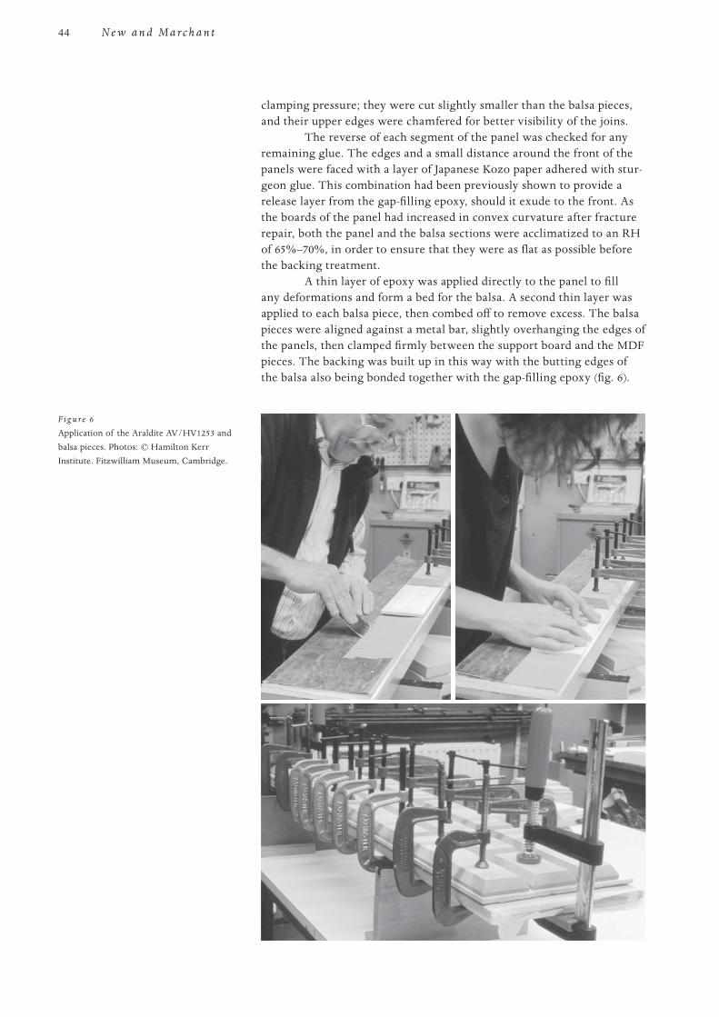
44
PROOF 1 2 3 4 5 6
N e w a n d M a r c h a n t
clamping pressure; they were cut slightly smaller than the balsa pieces, and their upper edges were chamfered for better visibility of the joins.
The reverse of each segment of the panel was checked for any remaining glue. The edges and a small distance around the front of the panels were faced with a layer of Japanese Kozo paper adhered with stur-geon glue. This combination had been previously shown to provide a release layer from the gap-filling epoxy, should it exude to the front. As the boards of the panel had increased in convex curvature after fracture repair, both the panel and the balsa sections were acclimatized to an RH of 65%–70%, in order to ensure that they were as flat as possible before the backing treatment.
A thin layer of epoxy was applied directly to the panel to fill any deformations and form a bed for the balsa. A second thin layer was applied to each balsa piece, then combed off to remove excess. The balsa pieces were aligned against a metal bar, slightly overhanging the edges of the panels, then clamped firmly between the support board and the MDF pieces. The backing was built up in this way with the butting edges of the balsa also being bonded together with the gap-filling epoxy (fig. 6).
F ig u re 6
Application of the Araldite AV/HV1253 and balsa pieces. Photos: © Hamilton Kerr Institute. Fitzwilliam Museum, Cambridge.
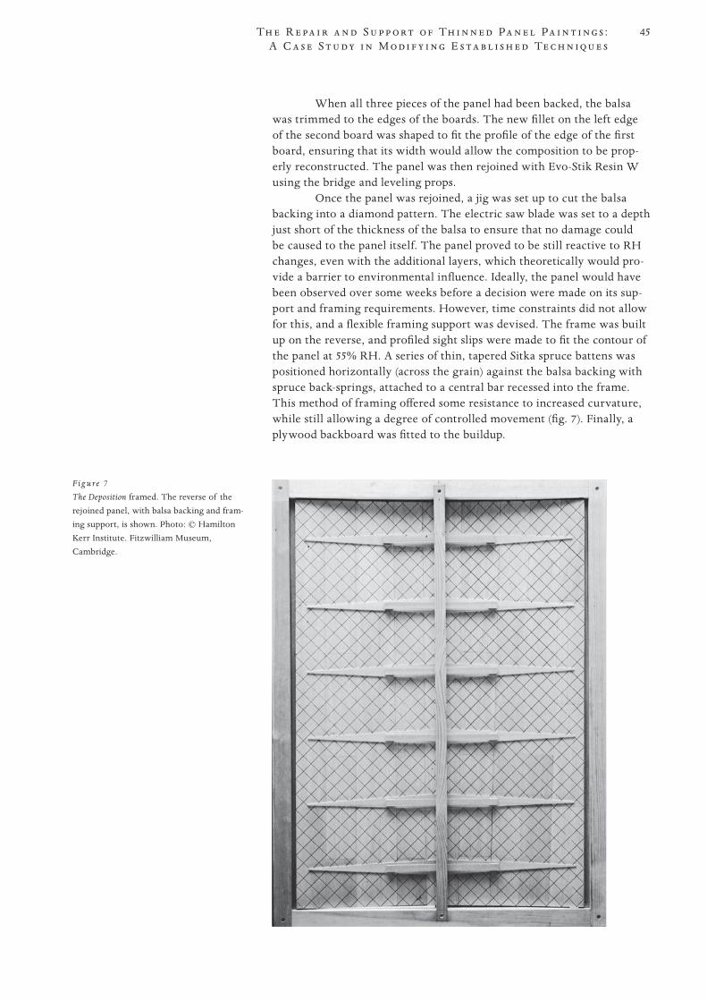
45
PROOF 1 2 3 4 5 6
Th e R e pa i r a n d S u p p o r t o f Th i n n e d Pa n e l Pa i n t i n g s : A C a s e S t u d y i n M o d i f y i n g E s t a b l i s h e d Te c h n i q u e s
When all three pieces of the panel had been backed, the balsa was trimmed to the edges of the boards. The new fillet on the left edge of the second board was shaped to fit the profile of the edge of the first board, ensuring that its width would allow the composition to be prop-erly reconstructed. The panel was then rejoined with Evo-Stik Resin W using the bridge and leveling props.
Once the panel was rejoined, a jig was set up to cut the balsa backing into a diamond pattern. The electric saw blade was set to a depth just short of the thickness of the balsa to ensure that no damage could be caused to the panel itself. The panel proved to be still reactive to RH changes, even with the additional layers, which theoretically would pro-vide a barrier to environmental influence. Ideally, the panel would have been observed over some weeks before a decision were made on its sup-port and framing requirements. However, time constraints did not allow for this, and a flexible framing support was devised. The frame was built up on the reverse, and profiled sight slips were made to fit the contour of the panel at 55% RH. A series of thin, tapered Sitka spruce battens was positioned horizontally (across the grain) against the balsa backing with spruce back-springs, attached to a central bar recessed into the frame. This method of framing offered some resistance to increased curvature, while still allowing a degree of controlled movement (fig. 7). Finally, a plywood backboard was fitted to the buildup.
F ig u re 7
The Deposition framed. The reverse of the rejoined panel, with balsa backing and fram-ing support, is shown. Photo: © Hamilton Kerr Institute. Fitzwilliam Museum, Cambridge.
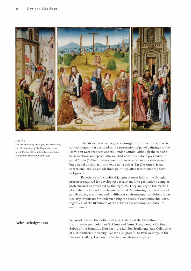
46
PROOF 1 2 3 4 5 6
N e w a n d M a r c h a n t
The above treatments give an insight into some of the practi-cal techniques that are used in the restoration of panel paintings at the Hamilton Kerr Institute and its London Studio, although the use of a balsa backing and epoxy adhesive had never been done previously. A panel 5 mm (0.2 in.) in thickness is often referred to as a thin panel, but a panel as thin as 1 mm (0.04 in.), such as The Deposition, is an exceptional challenge. All three paintings after treatment are shown in figure 8.
Experience and empirical judgment must inform the thought processes required for developing a treatment for a particularly complex problem such as presented by the tryptich. They are key to the method-ology that is chosen for each panel treated. Monitoring the curvature of panels during treatment and in different environmental conditions is par-ticularly important for understanding the needs of each individual case, regardless of the likelihood of the artwork’s remaining in a museum environment.
Acknowledgments We would like to thank the staff and students at the Hamilton Kerr
Institute—in particular Ian McClure and Jenny Rose, along with Simon Bobak of the Hamilton Kerr Institute London Studio and Jane Colbourne of Northumbria University. We are also grateful to Paul Ackroyd of the National Gallery, London, for his help in editing this paper.
F ig u re 8
The Presentation of the Virgin, The Deposition, and The Marriage of the Virgin after treat -ment. Photos: © Hamilton Kerr Institute. Fitzwilliam Museum, Cambridge.
47
PROOF 1 2 3 4 5 6
Th e R e pa i r a n d S u p p o r t o f Th i n n e d Pa n e l Pa i n t i n g s : A C a s e S t u d y i n M o d i f y i n g E s t a b l i s h e d Te c h n i q u e s
Notes 1 “The Antiques Erode Show” (a pun on the British television show The Antiques Roadshow),
Times (London), 4 Dec. 2002.
2 Analysis carried out by Ian Tyres, ARCUS Dendrochronology Laboratory, University of Sheffield.
3 Contaminants such as Beva 371 have been shown to weaken the bond when adhesives such as sturgeon glue or Evo-Stik Resin W are used. This was also likely to be the case with Paraloid B-67 (Young, New, and Marchant).
4 Recommended in conversation with George Bisacca, Metropolitan Museum of Art, New York.
5 Since completion of the treatment, work has been published on barrier materials for carv-able epoxy (Ellis and Heginbotham 2004, 23–37). Retrospectively, it seems that a barrier coat of Paraloid B-72, applied to the panel before the backing is applied, might have been advantageous. Although no empirical tests have been completed to date, further investiga-tion will be carried out into this aspect of treatment.
Materials and Suppliers Araldite AV/HV1253, Conservation Resources (UK) Ltd., Unit 2 Ashville Way, Off Watlington
Road, Cowley, Oxford OX4 6TU, UK.
Coconut shell flour, Hallmark Adhesives, Units 55–56 Hill Grove Business Park, Nazing Road, Nazing, Essex EN9 2HP, UK.
Phenolic resin microballoons, Marineware Ltd., 6 Crosshouse Centre, Crosshouse Road, Southampton, Hants SO14 5GZ, UK.
References Brewer, Jon Allison. 1998. Effects of reinforcements on the preservation of paintings on wood
panel. PhD diss., City University, London.
de la Rie, René. 1987. The influence of varnishes on the appearance of paintings. Studies in
Conservation 32:1–13.
Ellis, Lisa, and Arlen Heginbotham. 2004. An evaluation of four barrier-coating and epoxy combinations in the structural repair of wooden objects. Journal of the American Institute of
Conservation 43:23–37.
Glatigny, Jean-Albert. 1995. Backings of painted panels: Reinforcement and constraint. In The Structural Conservation of Panel Paintings: Proceedings of a Symposium at the J. Paul Getty
Museum, 24–28 April 1995, ed. Kathleen Dardes and Andrea Rothe, 364–70. Los Angeles: Getty Conservation Institute.
Marchant, Raymond. 1995. The development of a flexible attached auxiliary support. In The Structural Conservation of Panel Paintings: Proceedings of a Symposium at the J. Paul Getty
Museum, 24–28 April 1995, ed. Kathleen Dardes and Andrea Rothe, 382–402. Los Angeles: Getty Conservation Institute.
New, Britta. 2011. Aqueous facing: Materials and revised application methods. The Picture
Restorer 38 (Spring).
von Imhoff, Hans-Christoph. 1978. Reinforcing a thin panel painting. In Conservation of Woods
in Painting and the Decorative Arts, ed. Norman Brommelle, Anne Moncrieff, and Perry Smith, 157–63. London: International Institute for Conservation of Historic and Artistic Works.
48
PROOF 1 2 3 4 5 6
The thinning of the wooden support of paintings on panel was considered in the past and, in fact, until recent times the correct way to resolve the problem of warping, in order to render the painting flat again. The operation of reducing the thickness of the support was carried out on deformed panels according to their curvature, to allow the thinned support to be reinforced in a flat position with a rigid auxiliary support. Analysis of past interventions has demonstrated that this type of operation completely altered the work, exponentially increas-ing problems of stability and support of the surface. Our research consists of the application of a buffer system on the reverse of the panel, with the aim of artificially restoring the response of the support to gradients of humidity similar to what it might have had originally, in order to slow shrinkage and expan-sion and therefore deformation in response to hydrometric jumps. The buffer system has been in use for a decade now and has been successfully applied in many cases—an example being the Madonna and Child Enthroned with Saints Francis and Nicasio or Liberale (Pala di Castelfranco) by Giorgione (ca. 1504), in the Duomo of Castelfranco Veneto (Treviso).
Flattening and Thinning: A Few Historical Notes
The practice of thinning of panel paintings is an old one. In a document presented to the Republic of Venice dated 6 July 1777, which entrusts the project of restoring Venetian paintings to Pietro Edwards, it is mentioned that “the panel paintings will be straightened, however curved they may be” (Tiozzo 2000, 116–17). In 1866 the restoration manual by Ulisse Forni indicates, in reference to the methods for straightening curved panels, “you must reduce the thickness of all the panels with a plane, thinning it by a centimeter and half if they will take it” (Forni 2004, 58). A manual by Giovanni Secco Suardo published in the same year features an entire section on the straightening of panels which reads, “before proceeding to the actual operation of flattening, it is useful to thin them in order to make them as compliant as possible . . . you will undertake to thin them with the use of a plane that you judge to be best suited to the task” (Secco Suardo 1927, 77).
Until recently, thinning was considered a definitive solution to resolving the aesthetic and structural problems of the painting caused by warping of the support. Probably made more desirable by factors linked to the market, as well as a growing interest in art collecting that was typical of the twentieth century, the flatness of the panel clearly consti-tuted the fundamental feature for the narrowly aesthetic requirements
Structural and Climate Control Systems for Thinned Panel Paintings
Abstract
PierPaolo Monfardini
49S t r u c t u r a l a n d C l i m a t e C o n t r o l S y s t e m s f o r Th i n n e d Pa n e l Pa i n t i n g s
PROOF 1 2 3 4 5 6
involved in an appreciation of the artwork; there was no interest or con-cern whatsoever for the issues and demands involved in the preservation of the panel painting itself, which was often compromised irreparably.
After thinning, various rigid support systems were applied to keep the paintings flat. This included crosspieces dovetailed into a groove cut into the thickness of the support, metal crosspieces, and upside-down T-shaped crosspieces set within latches that were applied extensively throughout the twentieth century up to the present day (Secco Suardo 1927, 98–105). Other systems used were “Florentine-style” or “Viennese-style” cradling and the application of metal crosspieces in various forms as recommended by the Istituto Centrale per il Restauro (ICR) of Rome, starting in the 1950s and continuing to the present day (Carità 1953; 1956; Brandi 1959). This technique was imported into France as well, in particular to the Louvre (Bergeon Langle 2007). The ICR later ceased the application of metal crosspieces, in parallel with a progres-sive abandonment of the study of wooden supports. Even in recent years, in certain contexts, these rigid auxiliary supports continued to be used, even though there was growing awareness of the risks involved with their application (De Luca, Baldelli, and Zarelli 2004).
An analysis of these interventions has shown that this kind of operation completely alters the artwork, exponentially increasing prob-lems with the preservation of the paint and support. It is no accident that a considerable number of the panel paintings that underwent such radi-cal structural restorations often continue to exhibit both complex and chronic surface and structural problems.
Moreover, when a panel painting is thinned, technical and his-toric information that can be provided by the back of the panel is elimi-nated and lost. Fortunately, that was not the case in the recent discovery of the engraved date on the back of the Giotto polyptych now in the Pinacoteca Nazionale of Bologna (Cauzzi 2005). Intact painting supports made it possible to reconstruct the seventeenth-century cataloguing of the collection of Cardinal P. Aldobrandini through inscriptions on the panel backs by G. B. Agucchi (De Marchi 2004).
Wood and the Factor of Climate
Having considered briefly the historical reasoning that resulted in the operations of thinning and application of rigid auxiliary supports, let us examine the scientific reasons for the problems of preserving panel paint-ings, in order to develop reasonable proposals for their preservation.
The Climatic Factor
Wood is a hygroscopic material, and it therefore tends to remain in con-tinuous hygroscopic equilibrium with its surrounding environment by means of the phenomena of adsorption and desorption of water, result-ing in the shrinking and swelling of the mass of the wood. The climatic factor, therefore, constitutes a very influential element relating to the behavior of wood and can have negative consequences on the complex of heterogeneous materials that make up the panel painting. Secco Suardo emphasized the role of the climatic factor on the deterioration of panel paintings: “There are three causes that produce the lifting of paint. The first, which is the most common, is the alternation of hot and cold, dry and humid, which the panel has undergone for such a long time, and
50
PROOF 1 2 3 4 5 6
M o n f a r d i n i
with its continual expansion and shrinking, shifted the bed on which the paint is seated” (Secco Suardo 1927, 63).
The hygroscopic phenomenon was already well understood in early times and was taken into account in the construction of panel paintings to minimize the damaging effects. Cennini, in the fourteenth century, described the method for gluing fabric between the wood and the preparation to isolate wood movement from the paint layers, a technique used since ancient times (Cennini 1982, 119). The framing of panels was also considered significant, as Leonardo wrote: “. . . and put it in a frame in such a manner that it can swell and shrink depending on whether it is humid or dry” (Leonardo da Vinci 1492). This rationale continued to modern times when Forni wrote, “A framework fixed with screws will prevent the boards of the painting from moving as is natural to them with the variations of the seasons” (Forni 2004, 58).
Astonishingly, it still seems that many caretakers of artwork have virtually no understanding of the relationship between wood and climate. Moreover, in Italy in particular, collections are often housed in places that are not equipped with any climate control, mainly because of the historic nature of the buildings themselves—a situation that enables continued deterioration.
The hygroscopic behavior of wood is linked to the factor of time, inasmuch as adsorption and desorption take place through moisture gradients; therefore, the thicker the support, the slower the overall phe-nomena of shrinkage and swelling. Thinning of the wood makes it much more susceptible since it tends to accelerate the hygroscopic behavior rates of the panels. When tunnels of wood-boring insects are uncovered during thinning, the procedure results in a de facto increase of the sup-port’s surface area in contact with the environment and therefore pro-duces an imbalance due to increased hygroscopic exchange.
Anatomical Selection
The use of tangentially cut boards in the construction of supports is the main reason for the poor preservation of the supports. Such supports take on a curved shape during the shrinking phase because of a differ-ence of behavior between the internal and external faces of the same panel (the internal face was originally toward the center of the trunk, the external face toward the bark). This behavior was well known and is one of the reasons that, as early as the thirteenth century—when the produc-tion of artwork was technically better, as compared to the large-scale production undertaken in large Renaissance workshops—craftsmen tried to select panels that, as far as was possible, were radially cut, because in the shrinking phase they react similarly on both faces and are therefore not subject to warping.
The warped supports, made from tangentially cut boards, were thinned in order to be restored to a planar position. When tangential panels are thinned, although the forces of shrinking and swelling are reduced, the panels do not lose to any degree their dynamics of behavior. Indeed, thinning only increases them, because of an accentuated fragility produced by the weakening of the structure, a result of the loss of mate-rial mass during the thinning process.
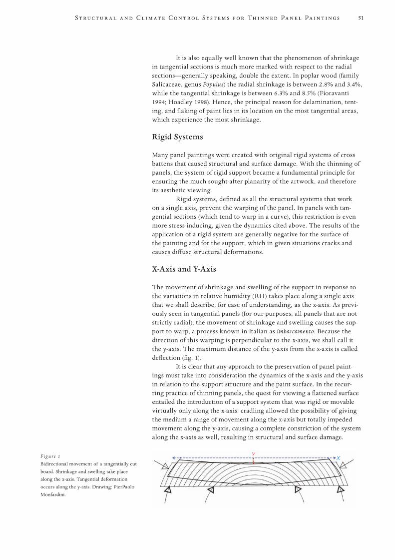
51S t r u c t u r a l a n d C l i m a t e C o n t r o l S y s t e m s f o r Th i n n e d Pa n e l Pa i n t i n g s
PROOF 1 2 3 4 5 6
It is also equally well known that the phenomenon of shrinkage in tangential sections is much more marked with respect to the radial sections—generally speaking, double the extent. In poplar wood (family Salicaceae, genus Populus) the radial shrinkage is between 2.8% and 3.4%, while the tangential shrinkage is between 6.3% and 8.5% (Fioravanti 1994; Hoadley 1998). Hence, the principal reason for delamination, tent-ing, and flaking of paint lies in its location on the most tangential areas, which experience the most shrinkage.
Rigid Systems
Many panel paintings were created with original rigid systems of cross battens that caused structural and surface damage. With the thinning of panels, the system of rigid support became a fundamental principle for ensuring the much sought-after planarity of the artwork, and therefore its aesthetic viewing.
Rigid systems, defined as all the structural systems that work on a single axis, prevent the warping of the panel. In panels with tan-gential sections (which tend to warp in a curve), this restriction is even more stress inducing, given the dynamics cited above. The results of the application of a rigid system are generally negative for the surface of the painting and for the support, which in given situations cracks and causes diffuse structural deformations.
X-Axis and Y-Axis
The movement of shrinkage and swelling of the support in response to the variations in relative humidity (RH) takes place along a single axis that we shall describe, for ease of understanding, as the x-axis. As previ-ously seen in tangential panels (for our purposes, all panels that are not strictly radial), the movement of shrinkage and swelling causes the sup-port to warp, a process known in Italian as imbarcamento. Because the direction of this warping is perpendicular to the x-axis, we shall call it the y-axis. The maximum distance of the y-axis from the x-axis is called deflection (fig. 1).
It is clear that any approach to the preservation of panel paint-ings must take into consideration the dynamics of the x-axis and the y-axis in relation to the support structure and the paint surface. In the recur-ring practice of thinning panels, the quest for viewing a flattened surface entailed the introduction of a support system that was rigid or movable virtually only along the x-axis: cradling allowed the possibility of giving the medium a range of movement along the x-axis but totally impeded movement along the y-axis, causing a complete constriction of the system along the x-axis as well, resulting in structural and surface damage.
F ig u re 1
Bidirectional movement of a tangentially cut board. Shrinkage and swelling take place along the x-axis. Tangential deformation occurs along the y-axis. Drawing: PierPaolo Monfardini.
YX
52
PROOF 1 2 3 4 5 6
M o n f a r d i n i
A System for Climatic and Structural Control
At this point, it is reasonable to wonder:
• Isitpossibletocreateanabsolutesystemofclimatecontrolforapainting on panel?
• Isaclimatecontrolledcontainersecure,whetherinamuseumoranenclosed space?
• Howshouldwetreatthevastnumberofpanelpaintingsthatarelocated in uncontrolled environments?
R. D. Buck posed these questions and more in his 1962 article “Is Cradling the Answer?” (Buck 1962). In his study of the relationship between artwork and environment, Buck emphasized such important con-cepts as “dimensional stabilization” and “moisture barriers” in a historical period during which an attempt was being made to introduce concepts of mechanics into the field of restoration, in particular for the application of sophisticated support systems through new materials (Buck 1978).
The dimensional stabilization of the support was sought through the application of moisture barriers. In an attempt to “isolate” the back of panel paintings, all sorts of materials, such as waxes, resins, and balsa wood, were tried. Slowing the reactiveness of the support to changes in the environment also diminishes the phenomena that lead to structural and surface damage. In various contexts, a number of impermeable barri-ers were also tested (Brewer 1991, 9–23).
An analysis of the behavior in terms of moisture gradients, already evaluated in the applications of moisture barriers, has brought to light the problems of the inversion of gradients in the presence of total barriers. It is precisely this phenomenon that causes an increased level of instability on the paint surface. Interestingly, Urbani and Mora, in their careful critique, identify the possible contraindication of the use of an impermeable barrier: “the advantage of this method . . . could be offset by the likely inversion of the gradients of humidity and tension within the panel itself, since it would now remain exposed to environmental variations, no longer from the back, but now from the painted surface” (Urbani and Mora 1973, 33).
Like Buck in his evaluations of moisture barriers, Mora intro-duced in clear terms the concept of a permeable barrier: “It would there-fore be extremely useful to carry out research intended to clarify whether it is possible to create barriers whose permeability can approximate as closely as possible that of the surface of the painting, so as to restore the equilibrium of the humidity gradients on both sides of the panel painting” (Urbani and Mora 1973, 33).
The application of a “contact” hygroscopic barrier would no longer be invasive and irreversible; the barrier would, instead, be truly removable, replaceable, and reversible, fulfilling the ideal concept of reconstructing the initial behavior of the panel before it was thinned, with a rheological evaluation of the support and an analysis of the humidity gradients. Aside from any considerations of various materials such as rubbers and synthetic polymers (i.e., polyethylene), an ideal hygroscopic barrier can consist of a thickness of wood, an excellent natural buffer material.
The application of this concept can be expressed as a buffer effect coupled with time as a factor. Therefore, the phenomena of the adsorption and desorption of moisture in the support are slowed down, and as a con-sequence, the related phenomena of swelling and shrinkage of the support
53S t r u c t u r a l a n d C l i m a t e C o n t r o l S y s t e m s f o r Th i n n e d Pa n e l Pa i n t i n g s
PROOF 1 2 3 4 5 6
itself are also reduced (Castelli 1998). The buffer effect of a hygroscopic barrier applied to the support can therefore allow us to reduce signifi-cantly the structural risks and the damage to the painted surface.
Controlled Curvature and Auxiliary Support
An intervention that has a history of many years of study and applica- tion and theoretically carries on the studies and the experiences cited above will be described (Monfardini 2005). Our research consists of the use of a buffer system applied to the back of the panel painting, with the objective of artificially reconstructing a behavior of the support similar to the initial gradients of humidity it had originally, in order to slow down the reactions of the support in response to hygrometric variations. It is applied predominantly to thinned or thin panels, which are inher-ently more susceptible and more fragile as compared to panels with an intact and substantial thickness. It seems to be a partial solution to their preservation because it decreases the response to fluctuations in RH while, at the same time, elastically controlling the movements along the x-axis and y-axis through a mobile auxiliary support system. In our case, the auxiliary support imitates an elastic method applied by the restoration laboratories of the Opificio delle Pietre Dure (Castelli and Santacesaria 1999, 190–92). It allows shrinkage and swelling to occur in an elastic manner along the line of deflection (the y-axis).
Various types of systems can be employed, but one fundamental element is the elastic control of the y-axis, preferably with a spring sys-tem that allows precise determination of the contrasting forces and that also measures metrically the fluctuations of the spring itself in response to the movements of the panel (Del Zotto and Tonini 1993).
The auxiliary support structure is constructed with radially cut wood (our preference is durmast oak) or with laminated wood. Wood further ensures a degree of flexibility in each individual crosspiece, mea-surable with great precision during the construction phase by means of a strain gauge. In this way, aside from the single points of elastic control provided by the springs, the overall flexibility of each element of the strainer can be evaluated.
The auxiliary support is applied after the panel has gained a degree of curvature that the tangential section induces by intrinsic behavior. The curvature taken on by the panel reduces the overall ten-sion in the most tangential area of the support, reducing in tandem the projections of such tension onto the surface of the painting—such as delamination, lifting, and flaking paint.
There can be no mistaking the difficulty of establishing with any precision the kind of curvature that a panel should be allowed. The procedure developed in our experience calls for working rigorously in a climate controlled environment with constant RH at 55%, where the artwork is placed in an acclimation phase for a period that varies accord-ing to the type of panel and the thickness of the support. Once the hygroscopic equilibrium of the support has been scientifically verified with a moisture meter, the rigid support system is gradually removed until it is entirely replaced with a temporary elastic support system. Strain gauges are used to measure the forces exerted by the support during the initial phase of curvature that the panel tends to assume. The resulting values will play an important role in the selection and
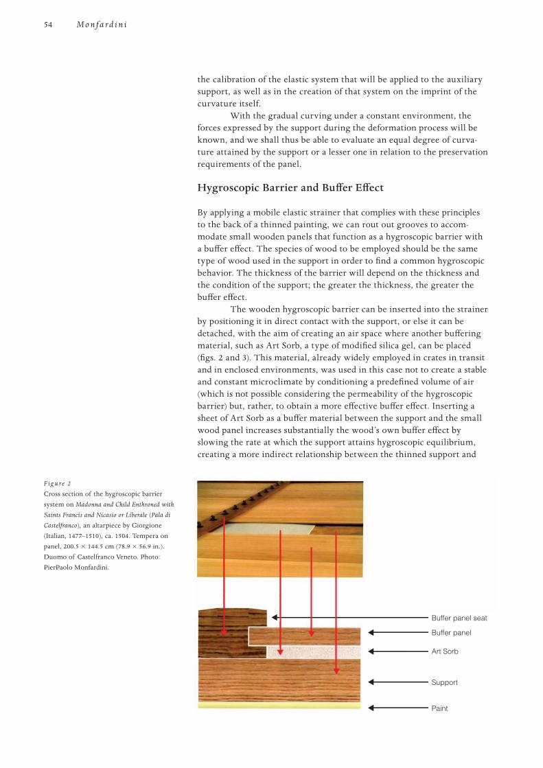
54
PROOF 1 2 3 4 5 6
M o n f a r d i n i
the calibration of the elastic system that will be applied to the auxiliary support, as well as in the creation of that system on the imprint of the curvature itself.
With the gradual curving under a constant environment, the forces expressed by the support during the deformation process will be known, and we shall thus be able to evaluate an equal degree of curva-ture attained by the support or a lesser one in relation to the preservation requirements of the panel.
Hygroscopic Barrier and Buffer Effect
By applying a mobile elastic strainer that complies with these principles to the back of a thinned painting, we can rout out grooves to accom-modate small wooden panels that function as a hygroscopic barrier with a buffer effect. The species of wood to be employed should be the same type of wood used in the support in order to find a common hygroscopic behavior. The thickness of the barrier will depend on the thickness and the condition of the support; the greater the thickness, the greater the buffer effect.
The wooden hygroscopic barrier can be inserted into the strainer by positioning it in direct contact with the support, or else it can be detached, with the aim of creating an air space where another buffering material, such as Art Sorb, a type of modified silica gel, can be placed (figs. 2 and 3). This material, already widely employed in crates in transit and in enclosed environments, was used in this case not to create a stable and constant microclimate by conditioning a predefined volume of air (which is not possible considering the permeability of the hygroscopic barrier) but, rather, to obtain a more effective buffer effect. Inserting a sheet of Art Sorb as a buffer material between the support and the small wood panel increases substantially the wood’s own buffer effect by slowing the rate at which the support attains hygroscopic equilibrium, creating a more indirect relationship between the thinned support and
Buffer panel seat
Buffer panel
Art Sorb
Support
Paint
F ig u re 2
Cross section of the hygroscopic barrier system on Madonna and Child Enthroned with
Saints Francis and Nicasio or Liberale (Pala di
Castelfranco), an altarpiece by Giorgione (Italian, 1477–1510), ca. 1504. Tempera on panel, 200.5 × 144.5 cm (78.9 × 56.9 in.). Duomo of Castelfranco Veneto. Photo: PierPaolo Monfardini.
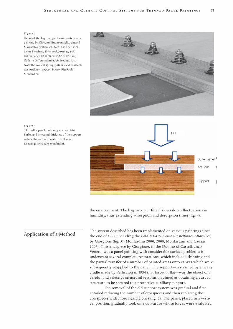
55S t r u c t u r a l a n d C l i m a t e C o n t r o l S y s t e m s f o r Th i n n e d Pa n e l Pa i n t i n g s
PROOF 1 2 3 4 5 6
the environment. The hygroscopic “filter” slows down fluctuations in humidity, thus extending adsorption and desorption times (fig. 4).
Application of a Method The system described has been implemented on various paintings since
the end of 1998, including the Pala di Castelfranco (Castelfranco Altarpiece) by Giorgione (fig. 5) (Monfardini 2000; 2008; Monfardini and Cauzzi 2007). This altarpiece by Giorgione, in the Duomo of Castelfranco Veneto, was a panel painting with considerable surface problems; it underwent several complete restorations, which included thinning and the partial transfer of a number of painted areas onto canvas which were subsequently reapplied to the panel. The support—restrained by a heavy cradle made by Pelliccioli in 1934 that forced it flat—was the object of a careful and selective structural restoration aimed at obtaining a curved structure to be secured to a protective auxiliary support.
The removal of the old support system was gradual and first entailed reducing the number of crosspieces and then replacing the crosspieces with more flexible ones (fig. 6). The panel, placed in a verti-cal position, gradually took on a curvature whose forces were evaluated
F ig u re 4
The buffer panel, buffering material (Art Sorb), and increased thickness of the support reduce the rate of moisture exchange. Drawing: PierPaolo Monfardini.
F ig u re 3
Detail of the hygroscopic barrier system on a painting by Giovanni Buonconsiglio, detto il Marescalco (Italian, ca. 1465–1535 or 1537), Saints Benedetto, Tecla, and Damiano, 1497. Oil on panel, 82 × 68 cm (32.3 × 26.8 in.). Gallerie dell’Accademia, Venice, inv. n. 97. Note the conical spring system used to attach the auxiliary support. Photo: PierPaolo Monfardini.
Buffer panel
RH
Art Sorb
Support
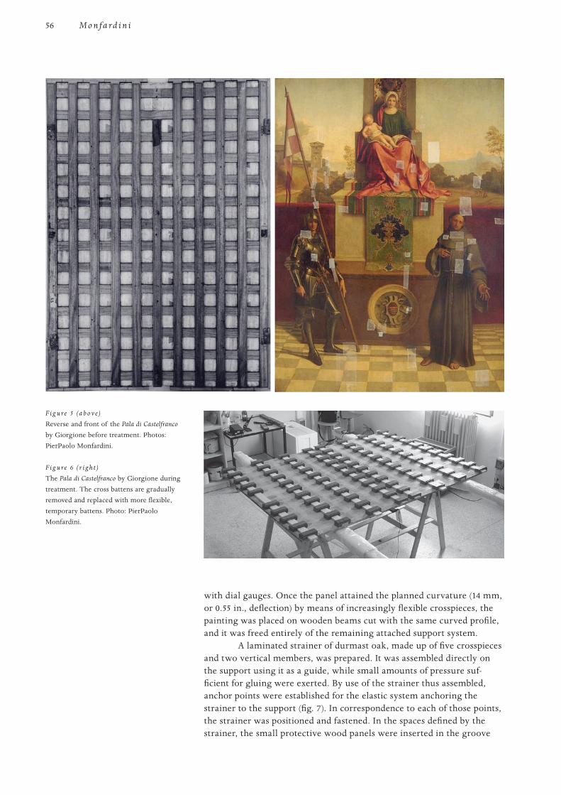
56
PROOF 1 2 3 4 5 6
M o n f a r d i n i
with dial gauges. Once the panel attained the planned curvature (14 mm, or 0.55 in., deflection) by means of increasingly flexible crosspieces, the painting was placed on wooden beams cut with the same curved profile, and it was freed entirely of the remaining attached support system.
A laminated strainer of durmast oak, made up of five crosspieces and two vertical members, was prepared. It was assembled directly on the support using it as a guide, while small amounts of pressure suf-ficient for gluing were exerted. By use of the strainer thus assembled, anchor points were established for the elastic system anchoring the strainer to the support (fig. 7). In correspondence to each of those points, the strainer was positioned and fastened. In the spaces defined by the strainer, the small protective wood panels were inserted in the groove
F ig u re 5 (a b o v e)
Reverse and front of the Pala di Castelfranco by Giorgione before treatment. Photos: PierPaolo Monfardini.
F ig u re 6 (r i g h t)
The Pala di Castelfranco by Giorgione during treatment. The cross battens are gradually removed and replaced with more flexible, temporary battens. Photo: PierPaolo Monfardini.
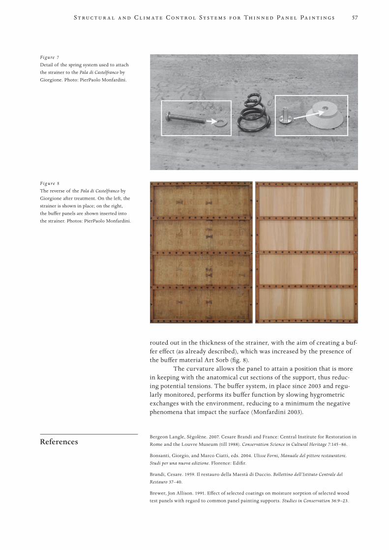
57S t r u c t u r a l a n d C l i m a t e C o n t r o l S y s t e m s f o r Th i n n e d Pa n e l Pa i n t i n g s
PROOF 1 2 3 4 5 6
routed out in the thickness of the strainer, with the aim of creating a buf-fer effect (as already described), which was increased by the presence of the buffer material Art Sorb (fig. 8).
The curvature allows the panel to attain a position that is more in keeping with the anatomical cut sections of the support, thus reduc-ing potential tensions. The buffer system, in place since 2003 and regu-larly monitored, performs its buffer function by slowing hygrometric exchanges with the environment, reducing to a minimum the negative phenomena that impact the surface (Monfardini 2003).
References Bergeon Langle, Ségolène. 2007. Cesare Brandi and France: Central Institute for Restoration in
Rome and the Louvre Museum (till 1988). Conservation Science in Cultural Heritage 7:145–86.
Bonsanti, Giorgio, and Marco Ciatti, eds. 2004. Ulisse Forni, Manuale del pittore restauratore.
Studi per una nuova edizione. Florence: Edifir.
Brandi, Cesare. 1959. Il restauro della Maestà di Duccio. Bollettino dell’Istituto Centrale del
Restauro 37–40.
Brewer, Jon Allison. 1991. Effect of selected coatings on moisture sorption of selected wood test panels with regard to common panel painting supports. Studies in Conservation 36:9–23.
Figure 7
Detail of the spring system used to attach the strainer to the Pala di Castelfranco by Giorgione. Photo: PierPaolo Monfardini.
F ig u re 8
The reverse of the Pala di Castelfranco by Giorgione after treatment. On the left, the strainer is shown in place; on the right, the buffer panels are shown inserted into the strainer. Photos: PierPaolo Monfardini.
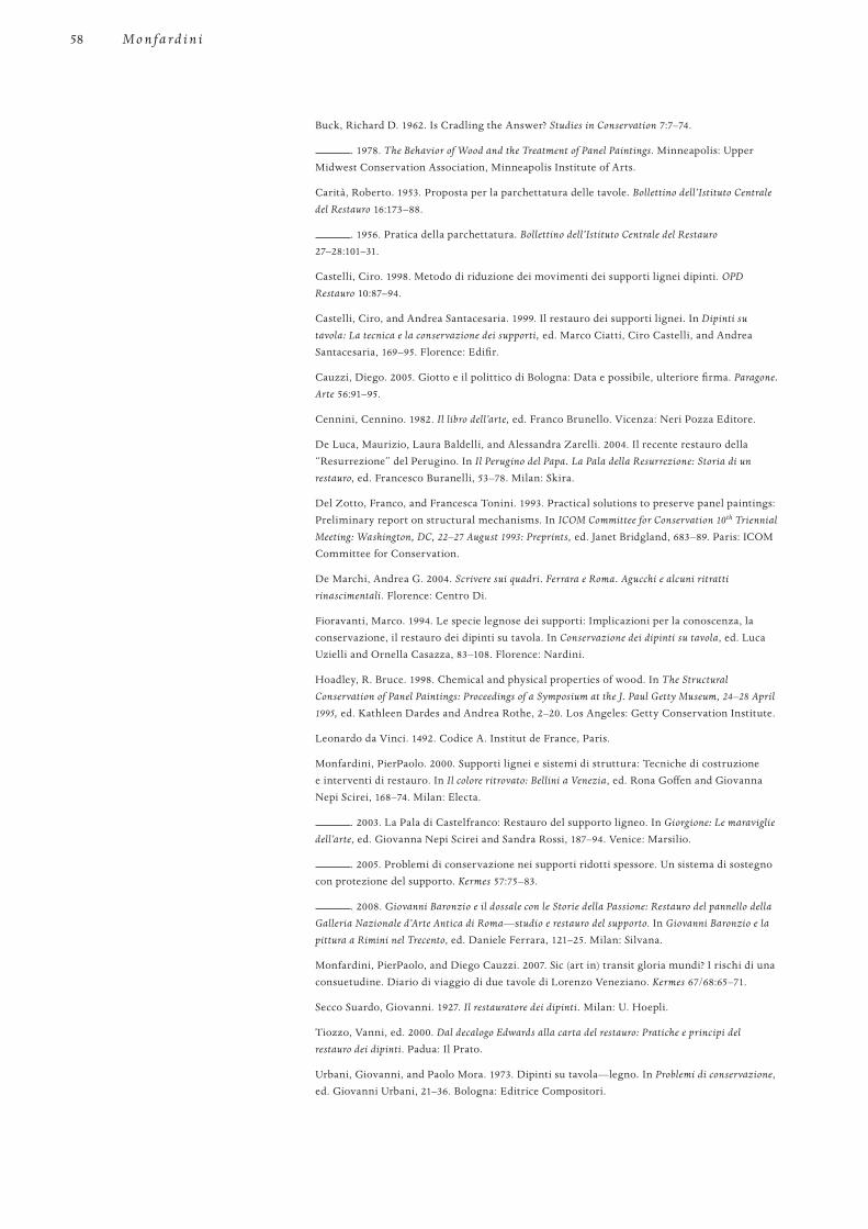
58
PROOF 1 2 3 4 5 6
M o n f a r d i n i
Buck, Richard D. 1962. Is Cradling the Answer? Studies in Conservation 7:7–74.
. 1978. The Behavior of Wood and the Treatment of Panel Paintings. Minneapolis: Upper Midwest Conservation Association, Minneapolis Institute of Arts.
Carità, Roberto. 1953. Proposta per la parchettatura delle tavole. Bollettino dell’Istituto Centrale
del Restauro 16:173–88.
. 1956. Pratica della parchettatura. Bollettino dell’Istituto Centrale del Restauro 27–28:101–31.
Castelli, Ciro. 1998. Metodo di riduzione dei movimenti dei supporti lignei dipinti. OPD
Restauro 10:87–94.
Castelli, Ciro, and Andrea Santacesaria. 1999. Il restauro dei supporti lignei. In Dipinti su
tavola: La tecnica e la conservazione dei supporti, ed. Marco Ciatti, Ciro Castelli, and Andrea Santacesaria, 169–95. Florence: Edifir.
Cauzzi, Diego. 2005. Giotto e il polittico di Bologna: Data e possibile, ulteriore firma. Paragone.
Arte 56:91–95.
Cennini, Cennino. 1982. Il libro dell’arte, ed. Franco Brunello. Vicenza: Neri Pozza Editore.
De Luca, Maurizio, Laura Baldelli, and Alessandra Zarelli. 2004. Il recente restauro della “Resurrezione” del Perugino. In Il Perugino del Papa. La Pala della Resurrezione: Storia di un
restauro, ed. Francesco Buranelli, 53–78. Milan: Skira.
Del Zotto, Franco, and Francesca Tonini. 1993. Practical solutions to preserve panel paintings: Preliminary report on structural mechanisms. In ICOM Committee for Conservation 10th Triennial
Meeting: Washington, DC, 22–27 August 1993: Preprints, ed. Janet Bridgland, 683–89. Paris: ICOM Committee for Conservation.
De Marchi, Andrea G. 2004. Scrivere sui quadri. Ferrara e Roma. Agucchi e alcuni ritratti
rinascimentali. Florence: Centro Di.
Fioravanti, Marco. 1994. Le specie legnose dei supporti: Implicazioni per la conoscenza, la conservazione, il restauro dei dipinti su tavola. In Conservazione dei dipinti su tavola, ed. Luca Uzielli and Ornella Casazza, 83–108. Florence: Nardini.
Hoadley, R. Bruce. 1998. Chemical and physical properties of wood. In The Structural
Conservation of Panel Paintings: Proceedings of a Symposium at the J. Paul Getty Museum, 24–28 April
1995, ed. Kathleen Dardes and Andrea Rothe, 2–20. Los Angeles: Getty Conservation Institute.
Leonardo da Vinci. 1492. Codice A. Institut de France, Paris.
Monfardini, PierPaolo. 2000. Supporti lignei e sistemi di struttura: Tecniche di costruzione e interventi di restauro. In Il colore ritrovato: Bellini a Venezia, ed. Rona Goffen and Giovanna Nepi Scirei, 168–74. Milan: Electa.
. 2003. La Pala di Castelfranco: Restauro del supporto ligneo. In Giorgione: Le maraviglie
dell’arte, ed. Giovanna Nepi Scirei and Sandra Rossi, 187–94. Venice: Marsilio.
. 2005. Problemi di conservazione nei supporti ridotti spessore. Un sistema di sostegno con protezione del supporto. Kermes 57:75–83.
. 2008. Giovanni Baronzio e il dossale con le Storie della Passione: Restauro del pannello della
Galleria Nazionale d’Arte Antica di Roma—studio e restauro del supporto. In Giovanni Baronzio e la
pittura a Rimini nel Trecento, ed. Daniele Ferrara, 121–25. Milan: Silvana.
Monfardini, PierPaolo, and Diego Cauzzi. 2007. Sic (art in) transit gloria mundi? I rischi di una consuetudine. Diario di viaggio di due tavole di Lorenzo Veneziano. Kermes 67/68:65–71.
Secco Suardo, Giovanni. 1927. Il restauratore dei dipinti. Milan: U. Hoepli.
Tiozzo, Vanni, ed. 2000. Dal decalogo Edwards alla carta del restauro: Pratiche e principi del
restauro dei dipinti. Padua: Il Prato.
Urbani, Giovanni, and Paolo Mora. 1973. Dipinti su tavola—legno. In Problemi di conservazione, ed. Giovanni Urbani, 21–36. Bologna: Editrice Compositori.
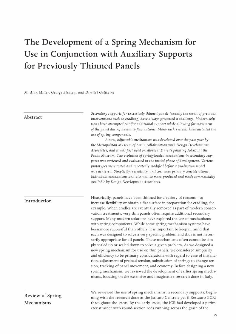
59
PROOF 1 2 3 4 5 6
Secondary supports for excessively thinned panels (usually the result of previous interventions such as cradling) have always presented a challenge. Modern solu-tions have attempted to offer additional support while allowing for movement of the panel during humidity fluctuations. Many such systems have included the use of spring components.
A new, adjustable mechanism was developed over the past year by the Metropolitan Museum of Art in collaboration with Design Development Associates, and it was first used on Albrecht Dürer’s painting Adam at the Prado Museum. The evolution of spring-loaded mechanisms in secondary sup-ports was reviewed and evaluated in the initial phase of development. Various prototypes were tested and repeatedly modified before a production model was achieved. Simplicity, versatility, and cost were primary considerations. Individual mechanisms and kits will be mass-produced and made commercially available by Design Development Associates.
Introduction Historically, panels have been thinned for a variety of reasons—to
increase flexibility or obtain a flat surface in preparation for cradling, for example. When cradles are eventually removed as part of modern conser-vation treatments, very thin panels often require additional secondary support. Many modern solutions have explored the use of mechanisms with spring components. While some spring mechanism systems have been more successful than others, it is important to keep in mind that each was designed to solve a very specific problem and thus is not neces-sarily appropriate for all panels. These mechanisms often cannot be sim-ply scaled up or scaled down to solve a given problem. As we designed a new spring mechanism for use on thin panels, we considered simplicity and efficiency to be primary considerations with regard to ease of installa-tion, adjustment of preload tension, substitution of springs to change ten-sion, tracking of panel movement, and economy. Before designing a new spring mechanism, we reviewed the development of earlier spring mecha-nisms, focusing on the extensive and imaginative research done in Italy.
Review of Spring Mechanisms
We reviewed the use of spring mechanisms in secondary supports, begin-ning with the research done at the Istituto Centrale per il Restauro (ICR) throughout the 1970s. By the early 1970s, the ICR had developed a perim-eter strainer with round-section rods running across the grain of the
The Development of a Spring Mechanism for Use in Conjunction with Auxiliary Supports for Previously Thinned Panels
Abstract
M. Alan Miller, George Bisacca, and Dimitri Galitzine
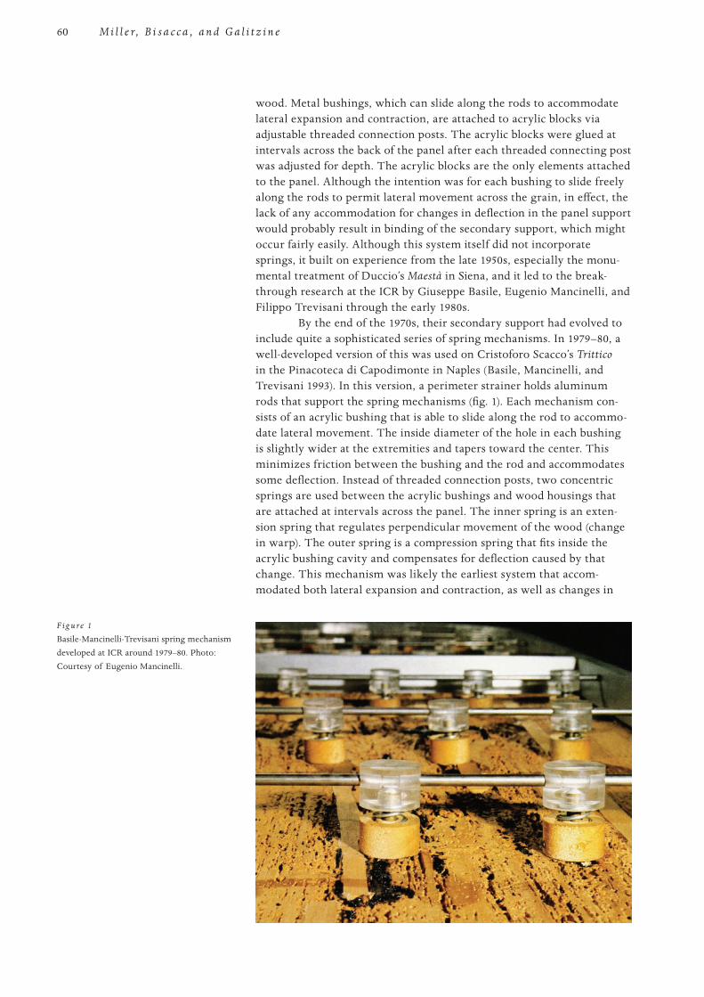
60
PROOF 1 2 3 4 5 6
M i l l e r, B i s a c c a , a n d G a l i t z i n e
wood. Metal bushings, which can slide along the rods to accommodate lateral expansion and contraction, are attached to acrylic blocks via adjustable threaded connection posts. The acrylic blocks were glued at intervals across the back of the panel after each threaded connecting post was adjusted for depth. The acrylic blocks are the only elements attached to the panel. Although the intention was for each bushing to slide freely along the rods to permit lateral movement across the grain, in effect, the lack of any accommodation for changes in deflection in the panel support would probably result in binding of the secondary support, which might occur fairly easily. Although this system itself did not incorporate springs, it built on experience from the late 1950s, especially the monu-mental treatment of Duccio’s Maestà in Siena, and it led to the break-through research at the ICR by Giuseppe Basile, Eugenio Mancinelli, and Filippo Trevisani through the early 1980s.
By the end of the 1970s, their secondary support had evolved to include quite a sophisticated series of spring mechanisms. In 1979–80, a well-developed version of this was used on Cristoforo Scacco’s Trittico in the Pinacoteca di Capodimonte in Naples (Basile, Mancinelli, and Trevisani 1993). In this version, a perimeter strainer holds aluminum rods that support the spring mechanisms (fig. 1). Each mechanism con-sists of an acrylic bushing that is able to slide along the rod to accommo-date lateral movement. The inside diameter of the hole in each bushing is slightly wider at the extremities and tapers toward the center. This minimizes friction between the bushing and the rod and accommodates some deflection. Instead of threaded connection posts, two concentric springs are used between the acrylic bushings and wood housings that are attached at intervals across the panel. The inner spring is an exten-sion spring that regulates perpendicular movement of the wood (change in warp). The outer spring is a compression spring that fits inside the acrylic bushing cavity and compensates for deflection caused by that change. This mechanism was likely the earliest system that accom-modated both lateral expansion and contraction, as well as changes in
F ig u re 1
Basile-Mancinelli-Trevisani spring mechanism developed at ICR around 1979–80. Photo: Courtesy of Eugenio Mancinelli.
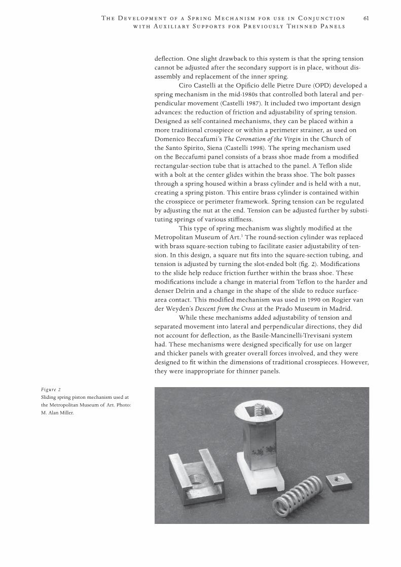
61
PROOF 1 2 3 4 5 6
Th e D e v e l o p m e n t o f a S p r i n g M e c h a n i s m f o r u s e i n C o n j u n c t i o n w i t h A u x i l i a r y S u p p o r t s f o r P r e v i o u s ly Th i n n e d Pa n e l s
deflection. One slight drawback to this system is that the spring tension cannot be adjusted after the secondary support is in place, without dis-assembly and replacement of the inner spring.
Ciro Castelli at the Opificio delle Pietre Dure (OPD) developed a spring mechanism in the mid-1980s that controlled both lateral and per-pendicular movement (Castelli 1987). It included two important design advances: the reduction of friction and adjustability of spring tension. Designed as self-contained mechanisms, they can be placed within a more traditional crosspiece or within a perimeter strainer, as used on Domenico Beccafumi’s The Coronation of the Virgin in the Church of the Santo Spirito, Siena (Castelli 1998). The spring mechanism used on the Beccafumi panel consists of a brass shoe made from a modified rectangular-section tube that is attached to the panel. A Teflon slide with a bolt at the center glides within the brass shoe. The bolt passes through a spring housed within a brass cylinder and is held with a nut, creating a spring piston. This entire brass cylinder is contained within the crosspiece or perimeter framework. Spring tension can be regulated by adjusting the nut at the end. Tension can be adjusted further by substi-tuting springs of various stiffness.
This type of spring mechanism was slightly modified at the Metropolitan Museum of Art.1 The round-section cylinder was replaced with brass square-section tubing to facilitate easier adjustability of ten-sion. In this design, a square nut fits into the square-section tubing, and tension is adjusted by turning the slot-ended bolt (fig. 2). Modifications to the slide help reduce friction further within the brass shoe. These modifications include a change in material from Teflon to the harder and denser Delrin and a change in the shape of the slide to reduce surface-area contact. This modified mechanism was used in 1990 on Rogier van der Weyden’s Descent from the Cross at the Prado Museum in Madrid.
While these mechanisms added adjustability of tension and separated movement into lateral and perpendicular directions, they did not account for deflection, as the Basile-Mancinelli-Trevisani system had. These mechanisms were designed specifically for use on larger and thicker panels with greater overall forces involved, and they were designed to fit within the dimensions of traditional crosspieces. However, they were inappropriate for thinner panels.
Figure 2
Sliding spring piston mechanism used at the Metropolitan Museum of Art. Photo: M. Alan Miller.
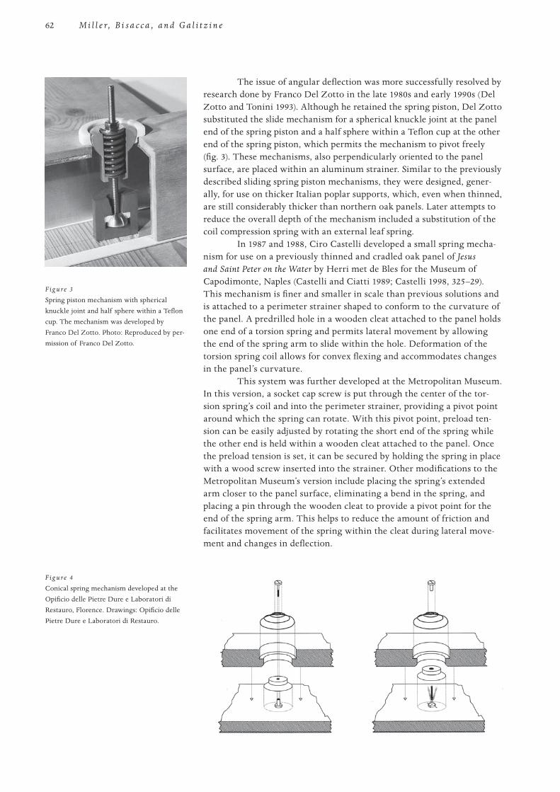
62
PROOF 1 2 3 4 5 6
M i l l e r, B i s a c c a , a n d G a l i t z i n e
The issue of angular deflection was more successfully resolved by research done by Franco Del Zotto in the late 1980s and early 1990s (Del Zotto and Tonini 1993). Although he retained the spring piston, Del Zotto substituted the slide mechanism for a spherical knuckle joint at the panel end of the spring piston and a half sphere within a Teflon cup at the other end of the spring piston, which permits the mechanism to pivot freely (fig. 3). These mechanisms, also perpendicularly oriented to the panel surface, are placed within an aluminum strainer. Similar to the previously described sliding spring piston mechanisms, they were designed, gener-ally, for use on thicker Italian poplar supports, which, even when thinned, are still considerably thicker than northern oak panels. Later attempts to reduce the overall depth of the mechanism included a substitution of the coil compression spring with an external leaf spring.
In 1987 and 1988, Ciro Castelli developed a small spring mecha-nism for use on a previously thinned and cradled oak panel of Jesus and Saint Peter on the Water by Herri met de Bles for the Museum of Capodimonte, Naples (Castelli and Ciatti 1989; Castelli 1998, 325–29). This mechanism is finer and smaller in scale than previous solutions and is attached to a perimeter strainer shaped to conform to the curvature of the panel. A predrilled hole in a wooden cleat attached to the panel holds one end of a torsion spring and permits lateral movement by allowing the end of the spring arm to slide within the hole. Deformation of the torsion spring coil allows for convex flexing and accommodates changes in the panel’s curvature.
This system was further developed at the Metropolitan Museum. In this version, a socket cap screw is put through the center of the tor-sion spring’s coil and into the perimeter strainer, providing a pivot point around which the spring can rotate. With this pivot point, preload ten-sion can be easily adjusted by rotating the short end of the spring while the other end is held within a wooden cleat attached to the panel. Once the preload tension is set, it can be secured by holding the spring in place with a wood screw inserted into the strainer. Other modifications to the Metropolitan Museum’s version include placing the spring’s extended arm closer to the panel surface, eliminating a bend in the spring, and placing a pin through the wooden cleat to provide a pivot point for the end of the spring arm. This helps to reduce the amount of friction and facilitates movement of the spring within the cleat during lateral move-ment and changes in deflection.
F ig u re 3
Spring piston mechanism with spherical knuckle joint and half sphere within a Teflon cup. The mechanism was developed by Franco Del Zotto. Photo: Reproduced by per-mission of Franco Del Zotto.
F ig u re 4
Conical spring mechanism developed at the Opificio delle Pietre Dure e Laboratori di Restauro, Florence. Drawings: Opificio delle Pietre Dure e Laboratori di Restauro.
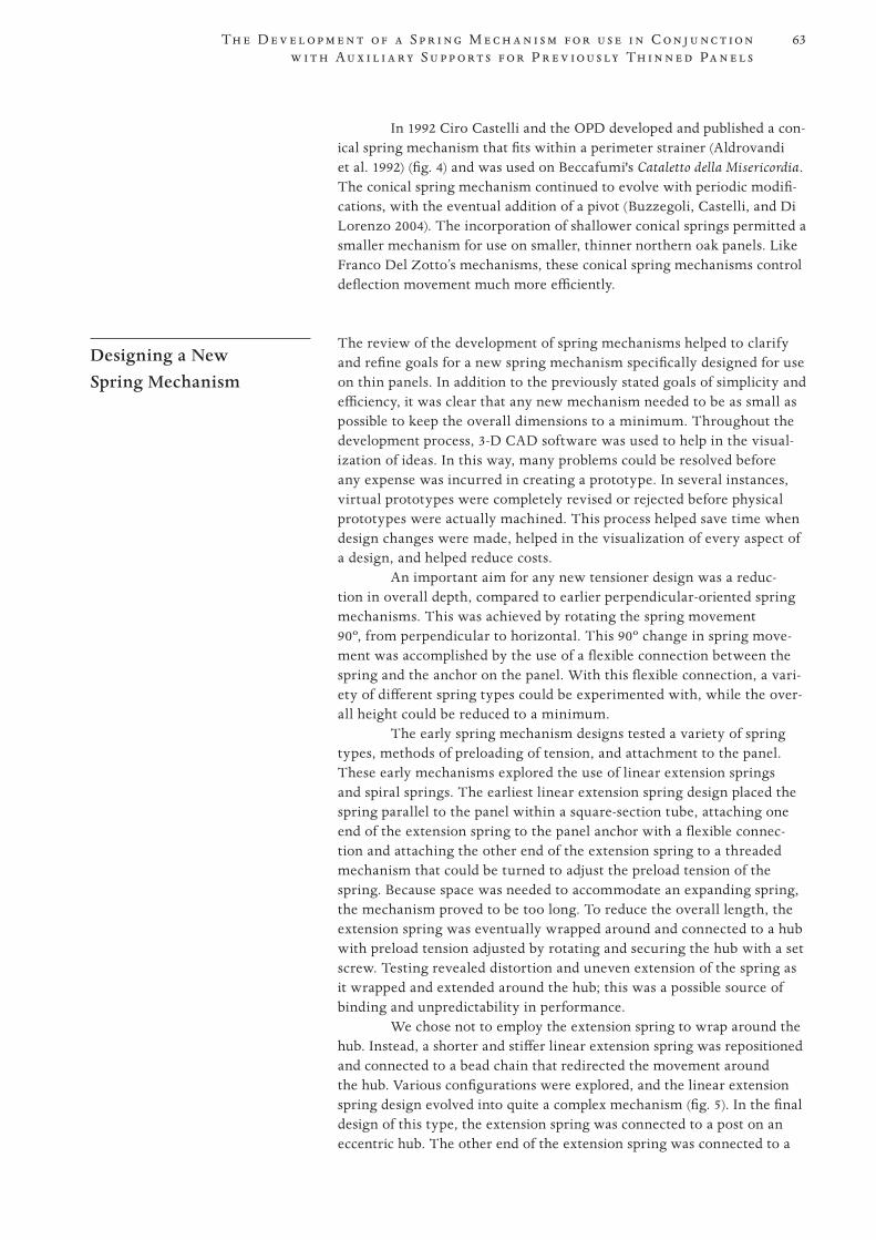
63
PROOF 1 2 3 4 5 6
Th e D e v e l o p m e n t o f a S p r i n g M e c h a n i s m f o r u s e i n C o n j u n c t i o n w i t h A u x i l i a r y S u p p o r t s f o r P r e v i o u s ly Th i n n e d Pa n e l s
In 1992 Ciro Castelli and the OPD developed and published a con-ical spring mechanism that fits within a perimeter strainer (Aldrovandi et al. 1992) (fig. 4) and was used on Beccafumi's Cataletto della Misericordia. The conical spring mechanism continued to evolve with periodic modifi-cations, with the eventual addition of a pivot (Buzzegoli, Castelli, and Di Lorenzo 2004). The incorporation of shallower conical springs permitted a smaller mechanism for use on smaller, thinner northern oak panels. Like Franco Del Zotto’s mechanisms, these conical spring mechanisms control deflection movement much more efficiently.
Designing a New Spring Mechanism
The review of the development of spring mechanisms helped to clarify and refine goals for a new spring mechanism specifically designed for use on thin panels. In addition to the previously stated goals of simplicity and efficiency, it was clear that any new mechanism needed to be as small as possible to keep the overall dimensions to a minimum. Throughout the development process, 3-D CAD software was used to help in the visual-ization of ideas. In this way, many problems could be resolved before any expense was incurred in creating a prototype. In several instances, virtual prototypes were completely revised or rejected before physical proto types were actually machined. This process helped save time when design changes were made, helped in the visualization of every aspect of a design, and helped reduce costs.
An important aim for any new tensioner design was a reduc-tion in overall depth, compared to earlier perpendicular-oriented spring mechanisms. This was achieved by rotating the spring movement 90º, from perpendicular to horizontal. This 90º change in spring move-ment was accomplished by the use of a flexible connection between the spring and the anchor on the panel. With this flexible connection, a vari-ety of different spring types could be experimented with, while the over-all height could be reduced to a minimum.
The early spring mechanism designs tested a variety of spring types, methods of preloading of tension, and attachment to the panel. These early mechanisms explored the use of linear extension springs and spiral springs. The earliest linear extension spring design placed the spring parallel to the panel within a square-section tube, attaching one end of the extension spring to the panel anchor with a flexible connec-tion and attaching the other end of the extension spring to a threaded mechanism that could be turned to adjust the preload tension of the spring. Because space was needed to accommodate an expanding spring, the mechanism proved to be too long. To reduce the overall length, the extension spring was eventually wrapped around and connected to a hub with preload tension adjusted by rotating and securing the hub with a set screw. Testing revealed distortion and uneven extension of the spring as it wrapped and extended around the hub; this was a possible source of binding and unpredictability in performance.
We chose not to employ the extension spring to wrap around the hub. Instead, a shorter and stiffer linear extension spring was repositioned and connected to a bead chain that redirected the movement around the hub. Various configurations were explored, and the linear extension spring design evolved into quite a complex mechanism (fig. 5). In the final design of this type, the extension spring was connected to a post on an eccentric hub. The other end of the extension spring was connected to a
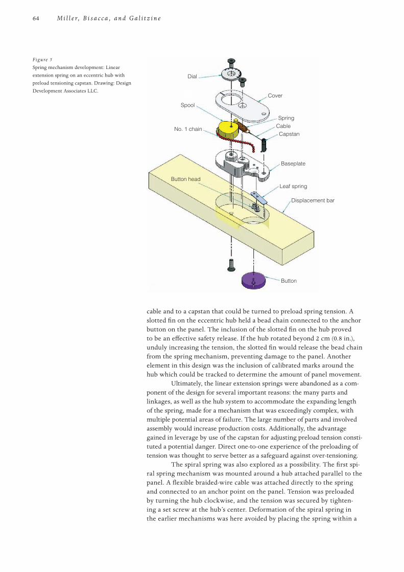
64
PROOF 1 2 3 4 5 6
M i l l e r, B i s a c c a , a n d G a l i t z i n e
cable and to a capstan that could be turned to preload spring tension. A slotted fin on the eccentric hub held a bead chain connected to the anchor button on the panel. The inclusion of the slotted fin on the hub proved to be an effective safety release. If the hub rotated beyond 2 cm (0.8 in.), unduly increasing the tension, the slotted fin would release the bead chain from the spring mechanism, preventing damage to the panel. Another element in this design was the inclusion of calibrated marks around the hub which could be tracked to determine the amount of panel movement.
Ultimately, the linear extension springs were abandoned as a com-ponent of the design for several important reasons: the many parts and linkages, as well as the hub system to accommodate the expanding length of the spring, made for a mechanism that was exceedingly complex, with multiple potential areas of failure. The large number of parts and involved assembly would increase production costs. Additionally, the advantage gained in leverage by use of the capstan for adjusting preload tension consti-tuted a potential danger. Direct one-to-one experience of the preloading of tension was thought to serve better as a safeguard against over-tensioning.
The spiral spring was also explored as a possibility. The first spi-ral spring mechanism was mounted around a hub attached parallel to the panel. A flexible braided-wire cable was attached directly to the spring and connected to an anchor point on the panel. Tension was preloaded by turning the hub clockwise, and the tension was secured by tighten-ing a set screw at the hub’s center. Deformation of the spiral spring in the earlier mechanisms was here avoided by placing the spring within a
Dial
No. 1 chain
Button head
Cover
SpringCableCapstan
Baseplate
Leaf spring
Displacement bar
Button
Spool
Figure 5
Spring mechanism development: Linear extension spring on an eccentric hub with preload tensioning capstan. Drawing: Design Development Associates LLC.
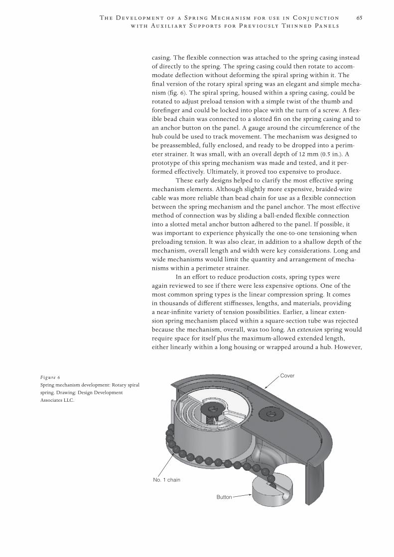
65
PROOF 1 2 3 4 5 6
Th e D e v e l o p m e n t o f a S p r i n g M e c h a n i s m f o r u s e i n C o n j u n c t i o n w i t h A u x i l i a r y S u p p o r t s f o r P r e v i o u s ly Th i n n e d Pa n e l s
casing. The flexible connection was attached to the spring casing instead of directly to the spring. The spring casing could then rotate to accom-modate deflection without deforming the spiral spring within it. The final version of the rotary spiral spring was an elegant and simple mecha-nism (fig. 6). The spiral spring, housed within a spring casing, could be rotated to adjust preload tension with a simple twist of the thumb and forefinger and could be locked into place with the turn of a screw. A flex-ible bead chain was connected to a slotted fin on the spring casing and to an anchor button on the panel. A gauge around the circumference of the hub could be used to track movement. The mechanism was designed to be preassembled, fully enclosed, and ready to be dropped into a perim-eter strainer. It was small, with an overall depth of 12 mm (0.5 in.). A proto type of this spring mechanism was made and tested, and it per-formed effectively. Ultimately, it proved too expensive to produce.
These early designs helped to clarify the most effective spring mechanism elements. Although slightly more expensive, braided-wire cable was more reliable than bead chain for use as a flexible connection between the spring mechanism and the panel anchor. The most effective method of connection was by sliding a ball-ended flexible connection into a slotted metal anchor button adhered to the panel. If possible, it was important to experience physically the one-to-one tensioning when preloading tension. It was also clear, in addition to a shallow depth of the mechanism, overall length and width were key considerations. Long and wide mechanisms would limit the quantity and arrangement of mecha-nisms within a perimeter strainer.
In an effort to reduce production costs, spring types were again reviewed to see if there were less expensive options. One of the most common spring types is the linear compression spring. It comes in thousands of different stiffnesses, lengths, and materials, providing a near-infinite variety of tension possibilities. Earlier, a linear exten-sion spring mechanism placed within a square-section tube was rejected because the mechanism, overall, was too long. An extension spring would require space for itself plus the maximum-allowed extended length, either linearly within a long housing or wrapped around a hub. However,
F ig u re 6
Spring mechanism development: Rotary spiral spring. Drawing: Design Development Associates LLC.
No. 1 chain
Cover
Button
66
PROOF 1 2 3 4 5 6
M i l l e r, B i s a c c a , a n d G a l i t z i n e
a compression spring is at its longest when at rest. By modifying the early linear extension spring design and instead using a compression spring, the mechanism length could be significantly reduced.
The final mechanism designs explored the use of linear com-pression springs housed within brass tubes. These final designs, with their use of compression springs, are similar to the spring piston systems developed by Ciro Castelli and Franco Del Zotto, except for one signifi-cant difference. In the Italian designs, movement of the panel is regulated by perpendicular compression of the spring via a stiff threaded post that runs through the center of the spring coil. Movement in the new design is translated through a flexible braided-wire cable connection. This flex-ible connection permits the movement to be translated 90° to horizontal, thus allowing for considerably shallower overall depth. Because the con-nection point is made with a ball-ended flexible braided-wire cable, it can also swivel easily to accommodate lateral movement and deflection of the panel.
To distinguish the final version of the spring mechanism from earlier versions, it is referred to as a spring tensioner; it is shorter, shal-lower, and narrower than the previous designs. The penultimate spring tensioner design is housed within a square-section tube with two nar-row slots milled on the top face. The compression spring sits between a piston plate and a tension-adjusting set screw. A flexible braided-wire cable running through the length of the spring passes through a center-ing Delrin (polyoxymethylene) cap and connects the piston plate to the slotted anchor button. The braided-wire cable is a fixed, predetermined length and provides a maximum displacement of 20 mm (0.8 in.). When the mechanism is at 5 mm (0.2 in.) above the panel, the spring is at rest. A modest amount of preload tension can be introduced simply by increasing the height of the mechanism by a few millimeters. Tension can be further adjusted by sliding the set screw along the first slot toward or away from the piston plate and tightening with a hex key. As tension on the spring changes, the piston plate, painted red, slides along the tube and is visible within the second slot. Gauge marks along the slot can be used to track one-to-one movement of the piston plate and the spring.
The spring tensioner is fully enclosed and preassembled with a linear compression spring appropriate for a wide range of uses. The com-pression spring, however, is easily substituted. This, combined with the preload tensioning aspect, provides a versatile yet simple spring mecha-nism. Its short length (55 mm, or 2.2 in.) and narrow diameter (10 mm, or 0.4 in.) allow for greater flexibility when the quantity and layout of the mechanisms within a perimeter strainer are determined. For example, the tensioners can be placed side by side in opposite directions so that the connection points are closer together, if required.
Although the tensioner can be used in a variety of ways, it is designed to be placed within a perimeter strainer constructed to match the curvature of the panel. The number and layout of the tensioners and the number and orientation of the crossbars (if any) should be predetermined when the perimeter strainers are designed. Quantity and layout of the ten-sioners may be debatable, but generally, more should be placed along the cross-grain direction. Care should be taken not to orient tensioners and the holes that pass through the strainer in a way that will weaken the cor-ner and cross-bar joints. Before the perimeter strainer is assembled, holes
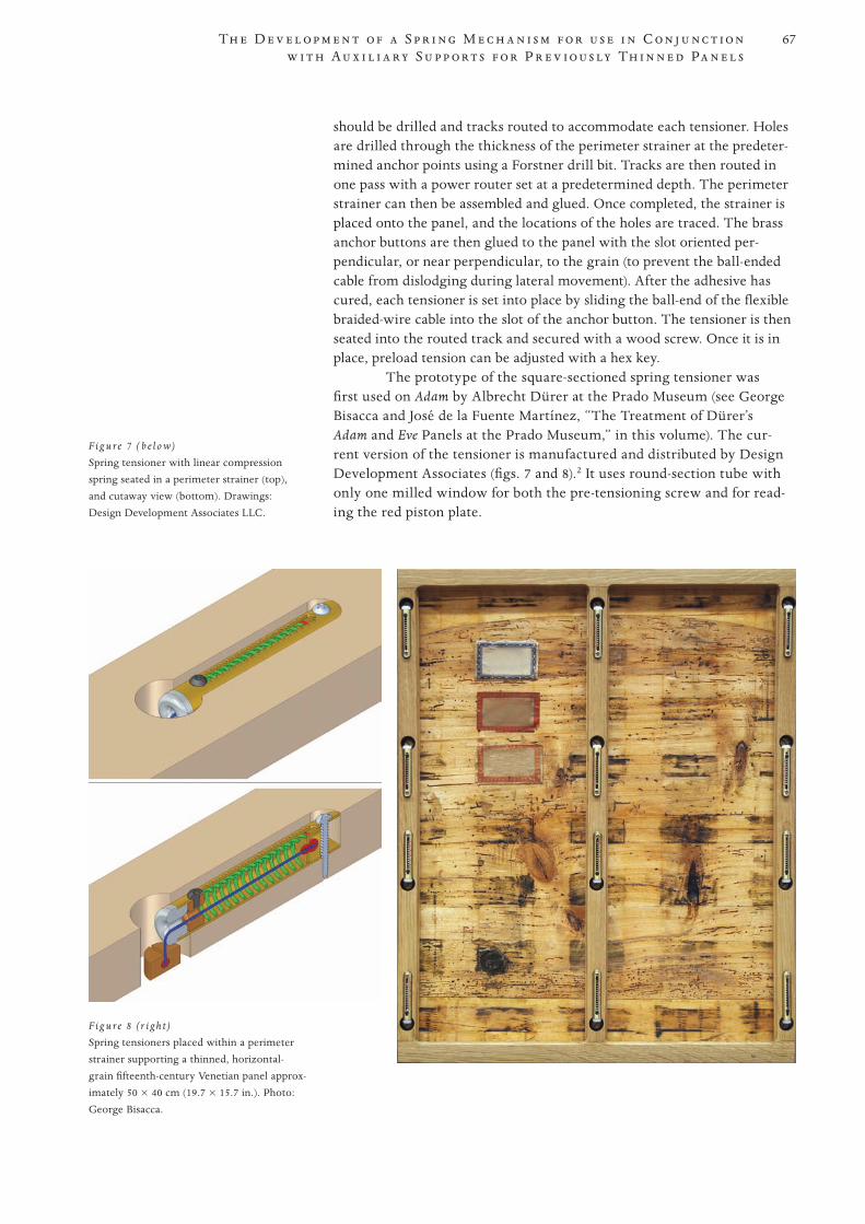
67
PROOF 1 2 3 4 5 6
Th e D e v e l o p m e n t o f a S p r i n g M e c h a n i s m f o r u s e i n C o n j u n c t i o n w i t h A u x i l i a r y S u p p o r t s f o r P r e v i o u s ly Th i n n e d Pa n e l s
should be drilled and tracks routed to accommodate each tensioner. Holes are drilled through the thickness of the perimeter strainer at the predeter-mined anchor points using a Forstner drill bit. Tracks are then routed in one pass with a power router set at a predetermined depth. The perimeter strainer can then be assembled and glued. Once completed, the strainer is placed onto the panel, and the locations of the holes are traced. The brass anchor buttons are then glued to the panel with the slot oriented per-pendicular, or near perpendicular, to the grain (to prevent the ball-ended cable from dislodging during lateral movement). After the adhesive has cured, each tensioner is set into place by sliding the ball-end of the flexible braided-wire cable into the slot of the anchor button. The tensioner is then seated into the routed track and secured with a wood screw. Once it is in place, preload tension can be adjusted with a hex key.
The prototype of the square-sectioned spring tensioner was first used on Adam by Albrecht Dürer at the Prado Museum (see George Bisacca and José de la Fuente Martínez, “The Treatment of Dürer’s Adam and Eve Panels at the Prado Museum,” in this volume). The cur-rent version of the tensioner is manufactured and distributed by Design Development Associates (figs. 7 and 8).2 It uses round-section tube with only one milled window for both the pre-tensioning screw and for read-ing the red piston plate.
F ig u re 8 (r i g h t)
Spring tensioners placed within a perimeter strainer supporting a thinned, horizontal-grain fifteenth-century Venetian panel approx-imately 50 × 40 cm (19.7 × 15.7 in.). Photo: George Bisacca.
F ig u re 7 ( b e l o w)
Spring tensioner with linear compression spring seated in a perimeter strainer (top), and cutaway view (bottom). Drawings: Design Development Associates LLC.
68
PROOF 1 2 3 4 5 6
M i l l e r, B i s a c c a , a n d G a l i t z i n e
Notes 1 This mechanism was developed in collaboration with Dimitri Galitzine, coauthor of
this paper.
2 Design Development Associates LLC, www.desdev.net.
References Aldrovandi, Alfredo, Nicoletta Bracci, Paola Bracco, Ciro Castelli, Ottavio Ciappi, Marco
Ciatti, Mauro Parri et al. 1992. Ricerche e interventi su alcuni dipinti di Domenico Beccafumi. OPD Restauro 4:28–50.
Basile, Giuseppe, Eugenio Mancinelli, and Filippo Trevisani. 1993. Sistemi di sostegno e con-trollo nei dipinti su tavola: Qualche esempio (e qualche problema). OPD Restauro 5:35–50.
Buzzegoli, Ezio, Ciro Castelli, and Andrea Di Lorenzo. 2004. Il “Compianto su Cristo morto” del Botticelli dal Museo Poldi Pezzoli di Milano: Note di minimo intervento e indagini diagnostiche non invasive. OPD Restauro 16:15–30.
Castelli, Ciro. 1987. Proposta per un nuovo tipo di traversa per dipinti su tavola. OPD Restauro
2:78–80.
. 1998. The restoration of panel painting supports: Some case histories. In The Structural
Conservation of Panel Paintings: Proceedings of a Symposium at the J. Paul Getty Museum, 24–28
April 1995, ed. Kathleen Dardes and Andrea Rothe, 316–40. Los Angeles: Getty Conservation Institute.
Castelli, Ciro, and Marco Ciatti. 1989. Proposta di intervento su particolari supporti lignei. OPD Restauro 1:108–11.
Del Zotto, Franco, and Francesca Tonini. 1993. Practical solutions to preserve panel paint-ings: Preliminary report on structural mechanisms. In ICOM Committee for Conservation, Tenth
Triennial Meeting, Washington, DC, USA, 22–27 August 1993: Preprints, ed. Janet Bridgland, 683–89. Paris: ICOM Committee for Conservation.
69
PROOF 1 2 3 4 5 6
This paper discusses the conservation treatment, undertaken between 2000 and 2006, of four panel paintings from the collection of the Kunsthistorisches Museum in Vienna. All of the panels were thinned and cradled during the nineteenth century. Warping and cracks had occurred because of shrinkage of the wood. In addition, flaking of the paint film and other negative effects made treatment inevitable. Because the wood panels had been thinned to a fraction of their origi-nal thickness, the construction of an auxiliary support system was necessary. The aim was to fabricate a secondary support that could be applied easily, with-out loss of original material, that would be completely reversible, and that would have sufficient flexibility to allow for the movement of wood under changing climatic conditions. The system selected is based on aluminum panels that have openings to allow access and visual control of the reverse of the painting. The design of the supporting units evolved incrementally: an adjustable system with a screw mechanism was followed by a more sophisticated, spring-loaded version that could be modified according to the size and weight of the panel. Although the springs allow movement of the wood panel in three dimensions, the system is strong enough to support the panel securely. In the latest version of the design, leaf springs were equipped with strain gauges to monitor the movement of the panel perpendicular to the front. Under construction (but not yet implemented) is an improved version that collects data for online processing or digital storage on a flash card or similar electronic storage medium.
Introduction Prior to the foundation of the Kunsthistorisches Museum (KHM) in
Vienna, the imperial collection of the Hapsburg family was displayed in the Belvedere Palace in Vienna. It was common practice in that period for original panels to be reduced in thickness and to be fitted with cra-dles. On this practice, Gerald Kaspar wrote, “The time during which the highest number of cradles were executed seems to coincide with the directorship of Josef Rebell (1825–28) and his successor Johann Krafft (1828–57), both having been artists and professors at the Academy. Unfortunately, we have no precise record of their activities. Only the numerous cradled panels bear witness to their activities” (Kaspar 1994, 40). Oberthaler adds that cradling “not only resulted in the loss of the original backs of the panels, it also meant the loss of valuable historical and technological information. Regrettable also is the difficult condition in which the weakened and cradled panels are now” (Oberthaler
The Development of Flexible Auxiliary Support Systems for Panel Paintings and the Monitoring of Panel Movement by Strain Gauges
Abstract
Ingrid Hopfner
70
PROOF 1 2 3 4 5 6
H o p f n e r
1996, 29). These observations hold true for the four paintings by Pietro Perugino, Jan Gossaert, Agnolo Bronzino, and Vincenzo Catena that are the subject of this paper.
According to Erhard Stöbe (Stöbe 1999, 55), the paintings from the Belvedere, as well as those in the Kunsthistorisches Museum, can be divided into four groups:
1. untreated objects with original painting on reverse2. various older reinforcements glued onto reduced supports3. cradles made under Josef Rebell (1825–28) and for the Imperial Gallery4. softer cradles for divided and reduced supports applied between about
1930 and 1953 (Franz Sochor)
Today’s conservators face the following main problems caused by the cradles: because of their having been thinned, the panels react more rapidly to climatic changes, and the overall static system is now out of balance. In most cases the panels, which now have an average thick-ness of 4–12 mm (0.2–0.5 in.), show a concave distortion rather than the more usual convex warp. The resulting tensions can cause a special form of warping (the “washboard effect”) or cracks. The effects on the paint film are destabilization, blistering, and paint loss.
Case Study 1: Perugino’s Virgin and Child with Two Female Saints (Saint Rosa and Saint Catherine)
Description
In most cases, after the cradle is removed, the static capacity of the thinned panel is insufficient, and stabilization by an auxiliary sup-port system is necessary. The development of the support system I have devised proceeded in steps, the f irst version having been imple-mented in 2000–2002 on a painting by Pietro Perugino, Virgin and Child with Two Female Saints (Saint Rosa and Saint Catherine) (KHM inv. no. 132, 86.6 × 62.8 cm [34.1 × 24.7 in.]), of 1493/95, and subsequently in 2003–4 on a painting by Jan Gossaert, Saint Luke Painting the Virgin (discussed below).
Perugino’s Virgin and Child with Two Female Saints came to the Imperial and Royal Picture Gallery from the Ecclesiastical Treasury in 1780. The appearance of the painting was impaired by flaking and losses to the paint layer, pronounced contraction crackle, solvent damage, abra-sion of the paint caused by previous unskilled attempts at cleaning, and disfiguring retouching. Restoration of the painting was made necessary by the occurrence of cracks in the panel and local adhesion problems affecting the ground and paint layers (Schaffer 2002/3).
Before restoration, the painting was subjected to scientific exam-ination by means of paint and binding medium analysis, X-radiography, and infrared reflectography. Around 1824, the picture, which is on a sin-gle poplar panel 4–6 mm (0.2 in.) thick with vertical grain, was fitted with a cradle composed of eight fixed vertical members and ten cross bat-tens. The cradle prevented the panel from adjusting to environmental changes, causing both stress to the wood and damage to the paint layer. It was thus necessary to remove the cradle. After the flaking paint was stabilized with sturgeon glue, the paint surface was secured with Japanese paper and Elvacite 2044 (a polybutylmethacrylate-based syn-thetic resin). A silicone imprint of the panel surface was taken on a low-
71
PROOF 1 2 3 4 5 6
Th e D e v e l o p m e n t o f F l e x i b l e A u x i l i a r y S u p p o r t S y s t e m s f o r Pa n e l Pa i n t i n g s a n d t h e M o n i t o r i n g o f Pa n e l M o v e m e n t b y S t r a i n G aug e s
pressure table. The painting was protected with plastic foil and then fixed on this silicone bed to allow the cross battens to be safely sawed from the cradle and the glued wood sections to be removed. After the edges were released from the silicone bed, the panel showed a slight convex warping. The warping prior to and after the removal of the cradle was monitored with a surface-measuring device with a laser instrument.1
Weakened points of the panel were secured with pieces of thin veneer. This method was first applied by Kaspar during the restoration of Albrecht Dürer’s Allerheiligenbild (Landauer Altar) and modified, primarily to allow for easy removal (Kaspar 1994, 45).
Auxiliary Support System
The essential idea was to provide support to the thinned wood panels and, at the same time, to allow for the inevitable slight movements caused by climatic changes. All materials included in the construction of the panel should meet the following requirements:
• Thepanelmustbemadeofstable,inorganicmaterials.• Theapplicationmustbenoninvasive.• Eachadditionmustbereversiblewithoutaddingmechanicalstresses
to the panel.• Theconstructionmustbeinproportionwiththesizeandweightof
the panel.• Nopartoftheconstruction(withtheexceptionoftheconnecting
posts) should be in contact with the reverse side of the panel.• Thebackofthepanelmustbevisible.• Althoughthepanelmustbestable,thesupportshouldallowforslight
movements via the connecting posts.• Theprecisepositionsoftheconnectingpostsaredictatedbythecon-
dition of the panel (additional support in weakened areas or near joins or cracks).
• Irregularitiesandunevennessofthepanelcanbecompensatedfor.• Thesupportingunitsandthepanelhavetoberemovable.• Thewholesystemcanbeenlarged.
With the cradle removed, the position of the supporting units was chosen according to the structure of the wood panel. First, the wood surface was primed with hydroxypropylcellulose (Klucel G dis-solved in ethanol), then an intermediate layer of a thin polyester fabric (Multi-Tetex TR art. Nr.PES-4/5, 100% polyester) was adhered with Beva 371 film.2 This should allow for the easy removal of the small pieces of veneer,3 which were finally attached with Beva 371 film applied with a warm spatula.
The advantages of using these materials to create the connection are multiple:
• itisaflexibleconnectionthatcompensatesforirregularitiesofthepanel;
• itactsasapredeterminedseparationpoint;• itiseasilyreversible;• replacementofasupportingunitiseasilypossible.
72
PROOF 1 2 3 4 5 6
H o p f n e r
The back of a Velcro strip must be able to adhere to Beva 371 film. Empirical tests have demonstrated that a 2 × 2 cm (0.8 × 0.8 in.) Velcro component can permanently withstand a 4.5 kg (9.9 lb.) shear load with minimal movement, and an approximately 3 kg (6.6 lb.) load perpendicu-lar to the point of attachment.
Before the additional support panel was applied, cracks in the wood panel itself were glued. For this operation, an intermediate alu-minum panel, attached to the supporting units already in place, was used. It provided stability and at the same time functioned as a gluing framework.
The support panel of the Perugino is made of an aluminum-resin compound material, Alucobond,4 and the connection to the wood panel consists of a number of connecting supporting units that are in equilib-rium in the neutral position. In contrast with the earlier rigid cradles, the connection between the wood panel and the secondary support is flex-ible; by means of the adjustment screws, it allows regulated movement of the panel in both concave and convex tendencies.
These supporting units are fixed to the wood panel in a com-pletely reversible way by means of a thin wood veneer, Beva 371 film, and Velcro fastening, and if necessary, they may be exchanged with minimal stress to the painting. The aluminum rear panel has openings to give access to the reverse of the panel. It is not in direct contact with the original panel and thus allows for equal climatic conditions on both sides of the painting. For maximum stabilization of the climatic conditions, the painting rests in a climate case. This is also the case for the three paintings that are discussed below.
Case Study 2: Gossaert’s Saint Luke Painting the Virgin
Description
Jan Gossaert’s painting from about 1520, Saint Luke Painting the Virgin (KHM inv. no. 894, 109.2 × 81.8 cm [43.0 × 32.2 in.]), was restored between November 2003 and February 2004 (Hopfner 2005). Both tech-nical and aesthetic considerations made the treatment necessary. There were cracks at the upper edge of the panel and flaking of the paint layer. The panel consists of three vertically joined members. In the early nineteenth century, the panel was thinned to 5–7 mm (0.2–0.3 in.) and mounted with a cradle. To reduce the tensions in the panel, it was neces-sary to remove the cradle and apply a flexible support system.
Conservation of the Panel
Prior to the removal of the cradle, all the points where tiny flaking and losses of paint had occurred needed to be stabilized. Overpainted areas and older fills were removed, as was an additional narrow strip of wood at the lower edge. Only around the cracks was the paint film secured with Japanese paper and Elvacite 2044 (acrylic resin) dissolved in white spirit. In this treatment, the front of the painting, which was protected by two layers of polyethylene foil (10–25 µm thick), was bedded in fine sand. The advantages over the silicone bed are twofold: the panel need not be fixed at the edges, and the panel is allowed to move slightly while the cradle is removed, so that no additional tensions can occur; and should the convex curvature increase, additional sand can be added
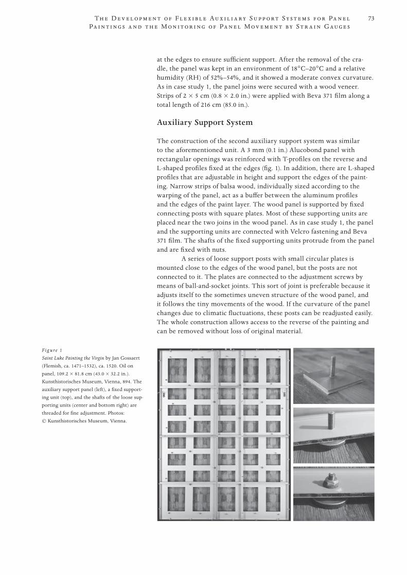
73
PROOF 1 2 3 4 5 6
Th e D e v e l o p m e n t o f F l e x i b l e A u x i l i a r y S u p p o r t S y s t e m s f o r Pa n e l Pa i n t i n g s a n d t h e M o n i t o r i n g o f Pa n e l M o v e m e n t b y S t r a i n G aug e s
at the edges to ensure sufficient support. After the removal of the cra-dle, the panel was kept in an environment of 18°C–20°C and a relative humidity (RH) of 52%–54%, and it showed a moderate convex curvature. As in case study 1, the panel joins were secured with a wood veneer. Strips of 2 × 5 cm (0.8 × 2.0 in.) were applied with Beva 371 film along a total length of 216 cm (85.0 in.).
Auxiliary Support System
The construction of the second auxiliary support system was similar to the aforementioned unit. A 3 mm (0.1 in.) Alucobond panel with rectangular openings was reinforced with T-profiles on the reverse and L-shaped profiles fixed at the edges (fig. 1). In addition, there are L-shaped profiles that are adjustable in height and support the edges of the paint-ing. Narrow strips of balsa wood, individually sized according to the warping of the panel, act as a buffer between the aluminum profiles and the edges of the paint layer. The wood panel is supported by fixed connecting posts with square plates. Most of these supporting units are placed near the two joins in the wood panel. As in case study 1, the panel and the supporting units are connected with Velcro fastening and Beva 371 film. The shafts of the fixed supporting units protrude from the panel and are fixed with nuts.
A series of loose support posts with small circular plates is mounted close to the edges of the wood panel, but the posts are not connected to it. The plates are connected to the adjustment screws by means of ball-and-socket joints. This sort of joint is preferable because it adjusts itself to the sometimes uneven structure of the wood panel, and it follows the tiny movements of the wood. If the curvature of the panel changes due to climatic fluctuations, these posts can be readjusted easily. The whole construction allows access to the reverse of the painting and can be removed without loss of original material.
F ig u re 1
Saint Luke Painting the Virgin by Jan Gossaert (Flemish, ca. 1471–1532), ca. 1520. Oil on panel, 109.2 × 81.8 cm (43.0 × 32.2 in.). Kunsthistorisches Museum, Vienna, 894. The auxiliary support panel (left), a fixed support-ing unit (top), and the shafts of the loose sup-porting units (center and bottom right) are threaded for fine adjustment. Photos: © Kunsthistorisches Museum, Vienna.
74
PROOF 1 2 3 4 5 6
H o p f n e r
Conclusion: Improvements Compared to the Perugino Support System
• fewerfixedconnectingpostsbutadditionalloosesupportsattheperimeter
• connectingpostswithaball-and-socketjoint• roundplatesinsteadofsquareones• loosesupportpoststhatcaneasilybereadjustedifthecurvatureofthe
panel changes
Case Study 3: Bronzino’s Holy Family with Saint Anne and Saint John the Baptist
Description
Agnolo Bronzino’s painting Holy Family with Saint Anne and Saint John the Baptist (KHM inv. no. 183, 124.5 × 99.2 cm [49.0 × 39.1 in.]), of around 1545/46, came to Vienna in 1792 from the archducal collection in Florence (Hopfner 2008). The poplar panel was reduced in thickness (it now measures 7.3–8.4 mm [0.3 in.]) and was given a cradle. The weight of the wood panel now is reduced to approximately 4.5 kg (9.9 lb.), whereas the cradle, which consisted of thirteen fixed vertical members and four-teen cross battens, amounted to 8.5 kg (18.7 lb.).
The conservation problems of the painting were comparable to those in cases 1 and 2: the warping of the panel led to numerous pinpoint losses; the panel surface showed concave warping in the lateral direction; small cracks occurred in the paint film close to the upper edge; addition-ally, the curious structure of the paint has led to the formation of a circu-lar craquelure pattern. The goals of the treatment, which was executed from October 2004 to November 2006, were the creation of structurally favorable conditions for the panel and the removal of the earlier interven-tions from the paint layer.
For the restoration of Bronzino’s painting, the auxiliary sup-port system was improved: The rigid support system now consists of an aluminum honeycomb composite panel, and the painting is held by two types of spring-loaded supporting units that are reversible without the need to remove the entire auxiliary support. In case of alterations of the wood panel due to climatic changes, the supporting units now can be easily readjusted.
Treatment of the Panel
After the paint film was stabilized and the insect channels filled,5 the edge of the panel was stabilized with Paraloid B-72. Prior to the removal of the cradle, the paint film was secured with Japanese paper and Elvacite 2044.
As in case study 2, the painting was placed in a sand bed while the cradle was removed. This arrangement enabled visual assessment of the warping. Moreover, the dimensional changes of the panel that occurred during this process were monitored by strain gauges. These were fixed to the back of the panel in four places and revealed changes in a range of only 22–129 µm.6
After the removal of the cradle, the panel was allowed to adjust for six weeks in an atmosphere of 53%–56% RH and a temperature of 20°C–22°C. It took on a slightly convex curvature; no attempts were made to straighten it out.
Originally, each joint of the large panel was reinforced with three tenons, which were secured by two dowels each. After the reduction of
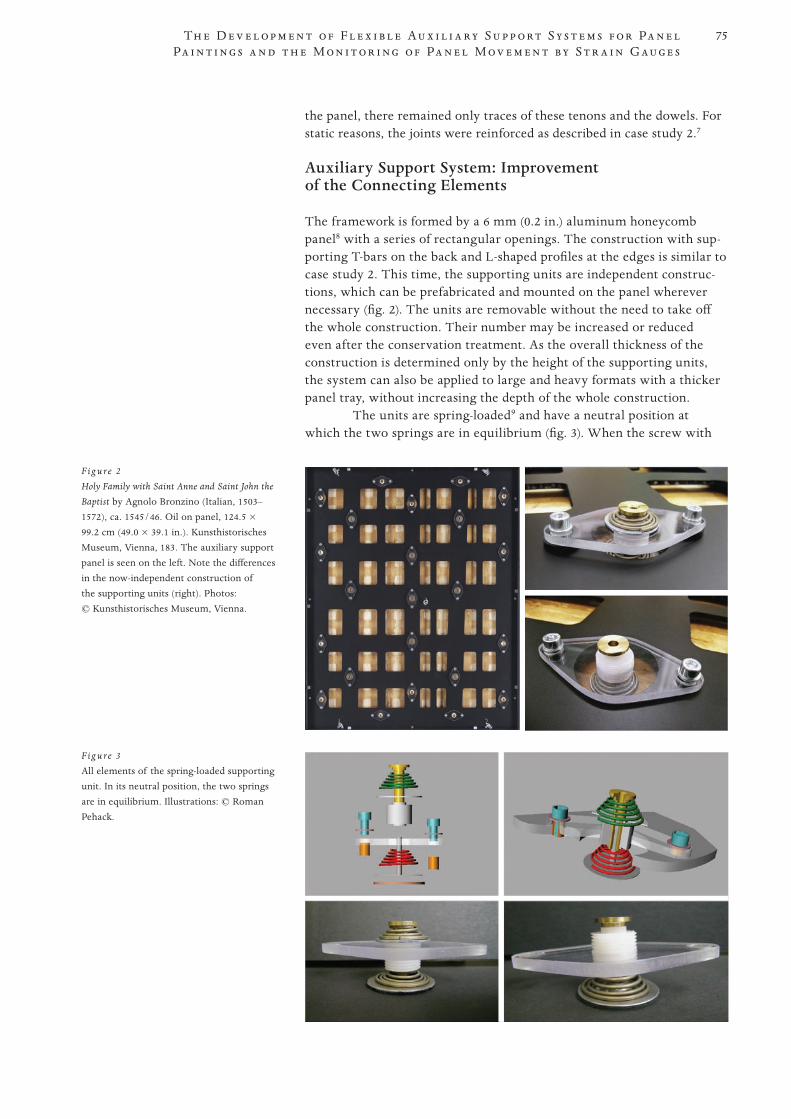
75
PROOF 1 2 3 4 5 6
Th e D e v e l o p m e n t o f F l e x i b l e A u x i l i a r y S u p p o r t S y s t e m s f o r Pa n e l Pa i n t i n g s a n d t h e M o n i t o r i n g o f Pa n e l M o v e m e n t b y S t r a i n G aug e s
the panel, there remained only traces of these tenons and the dowels. For static reasons, the joints were reinforced as described in case study 2.7
Auxiliary Support System: Improvement of the Connecting Elements
The framework is formed by a 6 mm (0.2 in.) aluminum honeycomb panel8 with a series of rectangular openings. The construction with sup-porting T-bars on the back and L-shaped profiles at the edges is similar to case study 2. This time, the supporting units are independent construc-tions, which can be prefabricated and mounted on the panel wherever necessary (fig. 2). The units are removable without the need to take off the whole construction. Their number may be increased or reduced even after the conservation treatment. As the overall thickness of the construction is determined only by the height of the supporting units, the system can also be applied to large and heavy formats with a thicker panel tray, without increasing the depth of the whole construction.
The units are spring-loaded9 and have a neutral position at which the two springs are in equilibrium (fig. 3). When the screw with
F ig u re 3
All elements of the spring-loaded supporting unit. In its neutral position, the two springs are in equilibrium. Illustrations: © Roman Pehack.
F ig u re 2
Holy Family with Saint Anne and Saint John the
Baptist by Agnolo Bronzino (Italian, 1503–1572), ca. 1545/46. Oil on panel, 124.5 × 99.2 cm (49.0 × 39.1 in.). Kunsthistorisches Museum, Vienna, 183. The auxiliary support panel is seen on the left. Note the differences in the now-independent construction of the supporting units (right). Photos: © Kunsthistorisches Museum, Vienna.
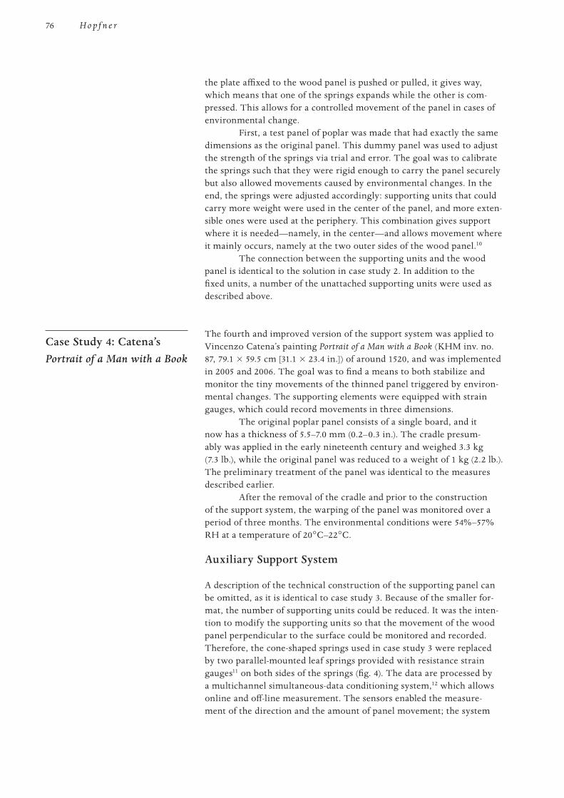
76
PROOF 1 2 3 4 5 6
H o p f n e r
the plate affixed to the wood panel is pushed or pulled, it gives way, which means that one of the springs expands while the other is com-pressed. This allows for a controlled movement of the panel in cases of environmental change.
First, a test panel of poplar was made that had exactly the same dimensions as the original panel. This dummy panel was used to adjust the strength of the springs via trial and error. The goal was to calibrate the springs such that they were rigid enough to carry the panel securely but also allowed movements caused by environmental changes. In the end, the springs were adjusted accordingly: supporting units that could carry more weight were used in the center of the panel, and more exten-sible ones were used at the periphery. This combination gives support where it is needed—namely, in the center—and allows movement where it mainly occurs, namely at the two outer sides of the wood panel.10
The connection between the supporting units and the wood panel is identical to the solution in case study 2. In addition to the fixed units, a number of the unattached supporting units were used as described above.
Case Study 4: Catena’s Portrait of a Man with a Book
The fourth and improved version of the support system was applied to Vincenzo Catena’s painting Portrait of a Man with a Book (KHM inv. no. 87, 79.1 × 59.5 cm [31.1 × 23.4 in.]) of around 1520, and was implemented in 2005 and 2006. The goal was to find a means to both stabilize and monitor the tiny movements of the thinned panel triggered by environ-mental changes. The supporting elements were equipped with strain gauges, which could record movements in three dimensions.
The original poplar panel consists of a single board, and it now has a thickness of 5.5–7.0 mm (0.2–0.3 in.). The cradle presum-ably was applied in the early nineteenth century and weighed 3.3 kg (7.3 lb.), while the original panel was reduced to a weight of 1 kg (2.2 lb.). The preliminary treatment of the panel was identical to the measures described earlier.
After the removal of the cradle and prior to the construction of the support system, the warping of the panel was monitored over a period of three months. The environmental conditions were 54%–57% RH at a temperature of 20°C–22°C.
Auxiliary Support System
A description of the technical construction of the supporting panel can be omitted, as it is identical to case study 3. Because of the smaller for-mat, the number of supporting units could be reduced. It was the inten-tion to modify the supporting units so that the movement of the wood panel perpendicular to the surface could be monitored and recorded. Therefore, the cone-shaped springs used in case study 3 were replaced by two parallel-mounted leaf springs provided with resistance strain gauges11 on both sides of the springs (fig. 4). The data are processed by a multichannel simultaneous-data conditioning system,12 which allows online and off-line measurement. The sensors enabled the measure-ment of the direction and the amount of panel movement; the system
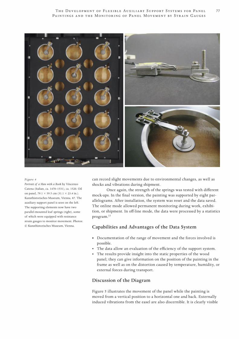
77
PROOF 1 2 3 4 5 6
Th e D e v e l o p m e n t o f F l e x i b l e A u x i l i a r y S u p p o r t S y s t e m s f o r Pa n e l Pa i n t i n g s a n d t h e M o n i t o r i n g o f Pa n e l M o v e m e n t b y S t r a i n G aug e s
can record slight movements due to environmental changes, as well as shocks and vibrations during shipment.
Once again, the strength of the springs was tested with different mock-ups. In the final version, the painting was supported by eight par-allelograms. After installation, the system was reset and the data saved. The online mode allowed permanent monitoring during work, exhibi-tion, or shipment. In off-line mode, the data were processed by a statistics program.13
Capabilities and Advantages of the Data System
• Documentation of the range of movement and the forces involved is possible.
• Thedataallowanevaluationoftheefficiencyofthesupportsystem.• Theresultsprovideinsightintothestaticpropertiesofthewood
panel; they can give information on the position of the painting in the frame as well as on the distortion caused by temperature, humidity, or external forces during transport.
Discussion of the Diagram
Figure 5 illustrates the movement of the panel while the painting is moved from a vertical position to a horizontal one and back. Externally induced vibrations from the easel are also discernible. It is clearly visible
Figure 4
Portrait of a Man with a Book by Vincenzo Catena (Italian, ca. 1470–1531), ca. 1520. Oil on panel, 79.1 × 59.5 cm (31.1 × 23.4 in.). Kunsthistorisches Museum, Vienna, 87. The auxiliary support panel is seen on the left. The supporting elements now have two parallel-mounted leaf springs (right), some of which were equipped with resistance strain gauges to monitor movement. Photos: © Kunsthistorisches Museum, Vienna.
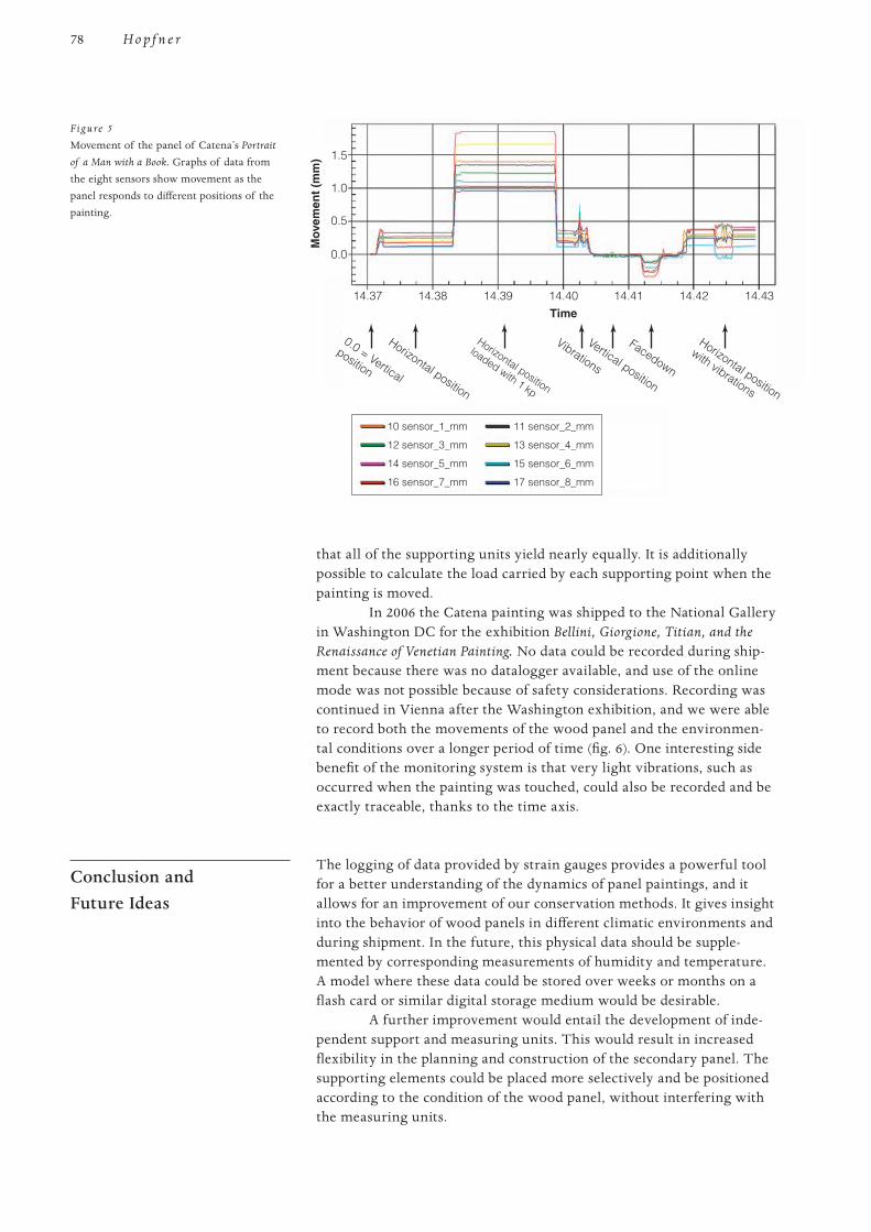
78
PROOF 1 2 3 4 5 6
H o p f n e r
that all of the supporting units yield nearly equally. It is additionally possible to calculate the load carried by each supporting point when the painting is moved.
In 2006 the Catena painting was shipped to the National Gallery in Washington DC for the exhibition Bellini, Giorgione, Titian, and the Renaissance of Venetian Painting. No data could be recorded during ship-ment because there was no datalogger available, and use of the online mode was not possible because of safety considerations. Recording was continued in Vienna after the Washington exhibition, and we were able to record both the movements of the wood panel and the environmen-tal conditions over a longer period of time (fig. 6). One interesting side benefit of the monitoring system is that very light vibrations, such as occurred when the painting was touched, could also be recorded and be exactly traceable, thanks to the time axis.
Conclusion and Future Ideas
The logging of data provided by strain gauges provides a powerful tool for a better understanding of the dynamics of panel paintings, and it allows for an improvement of our conservation methods. It gives insight into the behavior of wood panels in different climatic environments and during shipment. In the future, this physical data should be supple-mented by corresponding measurements of humidity and temperature. A model where these data could be stored over weeks or months on a flash card or similar digital storage medium would be desirable.
A further improvement would entail the development of inde-pendent support and measuring units. This would result in increased flexibility in the planning and construction of the secondary panel. The supporting elements could be placed more selectively and be positioned according to the condition of the wood panel, without interfering with the measuring units.
0.0 = Vertical
position
Horizontal position
Horizontal position
loaded with 1 kp
Vibrations
Vertical position
Facedown
Horizontal position
with vibrations
14.37
10 sensor_1_mm
12 sensor_3_mm
14 sensor_5_mm
16 sensor_7_mm
11 sensor_2_mm
13 sensor_4_mm
15 sensor_6_mm
17 sensor_8_mm
1.5
1.0
0.5
0.0
Mov
emen
t (m
m)
14.38 14.39 14.40Time
Hopfner_new Fig5.ai
14.41 14.42 14.43
Figure 5
Movement of the panel of Catena’s Portrait
of a Man with a Book. Graphs of data from the eight sensors show movement as the panel responds to different positions of the painting.
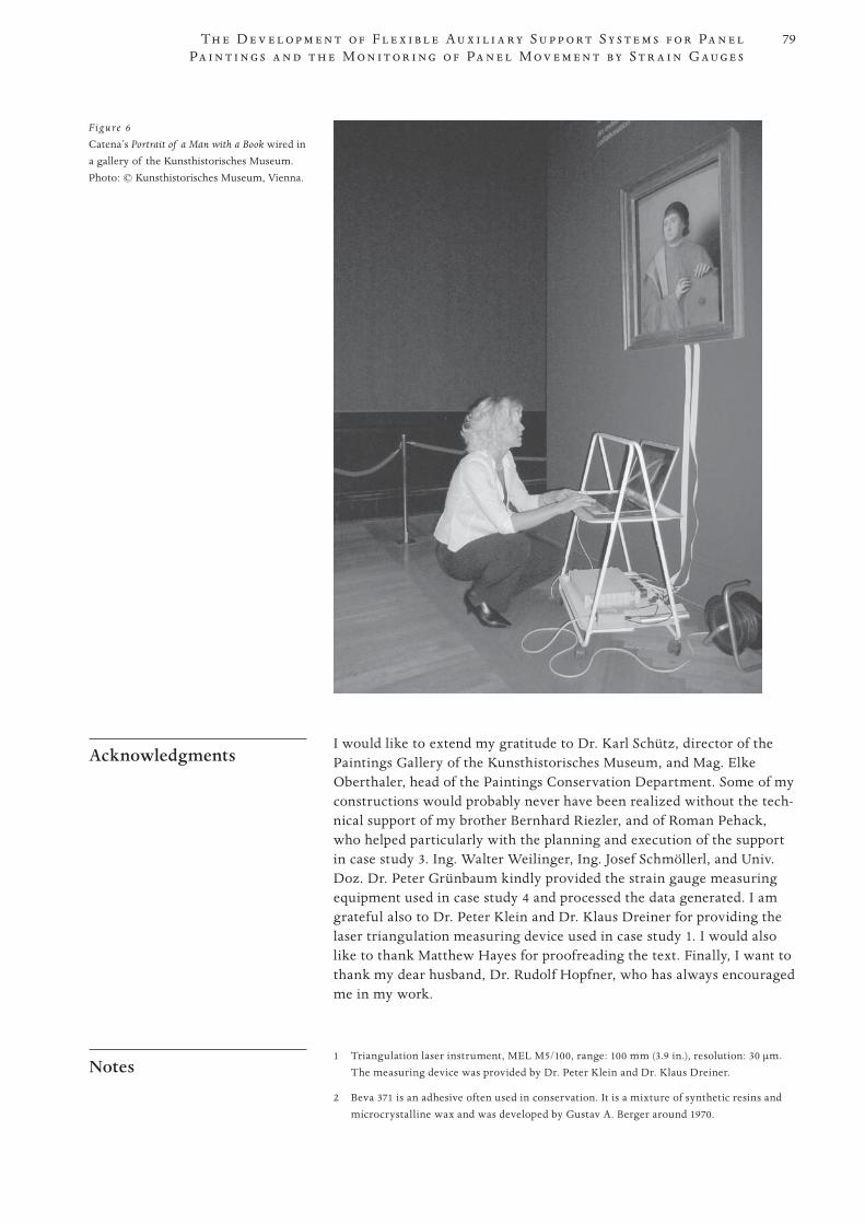
79
PROOF 1 2 3 4 5 6
Th e D e v e l o p m e n t o f F l e x i b l e A u x i l i a r y S u p p o r t S y s t e m s f o r Pa n e l Pa i n t i n g s a n d t h e M o n i t o r i n g o f Pa n e l M o v e m e n t b y S t r a i n G aug e s
Acknowledgments I would like to extend my gratitude to Dr. Karl Schütz, director of the
Paintings Gallery of the Kunsthistorisches Museum, and Mag. Elke Oberthaler, head of the Paintings Conservation Department. Some of my constructions would probably never have been realized without the tech-nical support of my brother Bernhard Riezler, and of Roman Pehack, who helped particularly with the planning and execution of the support in case study 3. Ing. Walter Weilinger, Ing. Josef Schmöllerl, and Univ. Doz. Dr. Peter Grünbaum kindly provided the strain gauge measuring equipment used in case study 4 and processed the data generated. I am grateful also to Dr. Peter Klein and Dr. Klaus Dreiner for providing the laser triangulation measuring device used in case study 1. I would also like to thank Matthew Hayes for proofreading the text. Finally, I want to thank my dear husband, Dr. Rudolf Hopfner, who has always encouraged me in my work.
Notes 1 Triangulation laser instrument, MEL M5/100, range: 100 mm (3.9 in.), resolution: 30 µm.
The measuring device was provided by Dr. Peter Klein and Dr. Klaus Dreiner.
2 Beva 371 is an adhesive often used in conservation. It is a mixture of synthetic resins and microcrystalline wax and was developed by Gustav A. Berger around 1970.
Figure 6
Catena’s Portrait of a Man with a Book wired in a gallery of the Kunsthistorisches Museum. Photo: © Kunsthistorisches Museum, Vienna.
80
PROOF 1 2 3 4 5 6
H o p f n e r
3 Walnut veneer with a thickness of 0.3 mm (0.01 in.). This was sanded, treated with Paraloid B-67, and sanded again for maximum smoothness.
4 Alucobond is a sandwich of two sheets of aluminum with a core of polyethylene; it has a matte surface. An Oddy test by our Conservation Science Department gave a negative result.
5 A fill material made of club moss spores and Plexisol P550 TB 40% was used. Plexisol P550 is a thermoplastic synthetic resin (Tg 25°C) with a high viscosity; it is soluble in nonpolar solvents (white spirit).
6 The measuring equipment and the software support were provided by Hottinger Baldwin Messtechnik GmbH (HBM), Lehmböckgasse 63/2, 1230 Vienna, Austria. www.hbm.com.
7 In the area where the 5 × 2 cm (2.0 × 0.8 in.) wood veneer was applied with Beva 371 film along a total length of 2 × 124.5 cm (0.8 × 49.0 in.), the wood was initially treated with hydroxypropylcellulose (Klucel G dissolved in ethanol).
8 For the construction, a 6 mm (0.2 in.) thick Alucore honeycomb panel, provided by the Alusuisse-Austria Company, was used. Early in 2005, an Oddy test no. 56/04 was performed in the museum’s Conservation Science Department, which indicated that the panel emits no corrosive components.
9 Rudolf Tmej GmbH, Factory for Technical Springs. Conical helical springs: inner dimen-sions 12 + 0.5/–0 mm / 25 + 2/–0 mm; wire thickness 1.5 mm diameter; total 5 coils; unstressed length (L0) = 15 mm; force at 0.5 L0 F1 = 5.0 kPa.
10 Roman Pehack planned and executed this construction.
11 Type 3/350LE11V, resistance: 350 ohm +/–0.35%, k-factor: 2.05 +/–1%, cross sensitivity: –0.1%.
12 Spider 8 with Catman software provided by HBM (see note 6).
13 Measurement accuracy: 0.001 mm; 1 g = 0.1 N.
Materials and Suppliers Alucore and Alucobond, Alusuisse-Austria GmbH, Slamastraße 43, 1230 Vienna, Austria.
www.alusuisse.at.
Beva 371 film (25 µm thick), Kremer Pigmente GmbH and Co. KG, Hauptstraße 41–47, D-88317 Aichstetten/Allgäu, Germany. www.kremer-pigmente.com.
Cell Rubber (closed and open), Franz Nuschei KG, Neubaugasse 31, Postfach 90, 1071 Vienna, Austria. www.nuschei.com.
Club moss spores, Kremer Pigmente GmbH and Co. KG, Hauptstraße 41–47, D-88317 Aichstetten/Allgäu, Germany. www.kremer-pigmente.com.
Elvacite 2044, Lucite International Speciality Polymer and Resins Ltd., Horndale Ave., Newton Aycliffe, County Durham DL5 6YE, UK. www.luciteinternational.com.
Plexisol P550 40%, Lascaux Colours and Restauro, Barbara Diethelm AG, Zürichstraße 42, CH-8306 Brüttisellen, Switzerland. www.lascaux.ch.
Polyester fabric (Multi-Tetex TR art. Nr.PES 4/5, 100% polyester), Putz Drucktechnik Ges m.b.H., Shuttleworthstr. 27–29, 1210 Vienna, Austria. www.putz.at.
Silicone rubber, Elastosil M 4670 A+B, Wacker Chemie GmbH, Max-Scheidhauf-Str. 25, D-87437 Kempten, Germany. www.wacker.com.
Strain gauges, Hottinger Baldwin Messtechnik GmbH, Lehmböckgasse 63/2, 1230 Vienna, Austria. www.hbm.com.
Technical springs, Rudolf Tmej GmbH, Factory for Technical Springs, Nordwestbahnstraße 77–79, 1200 Vienna, Austria. www.tmej.at.
81
PROOF 1 2 3 4 5 6
Th e D e v e l o p m e n t o f F l e x i b l e A u x i l i a r y S u p p o r t S y s t e m s f o r Pa n e l Pa i n t i n g s a n d t h e M o n i t o r i n g o f Pa n e l M o v e m e n t b y S t r a i n G aug e s
References Hopfner, Ingrid. 2005. Jan Gossaert gen. Mabuse: Der Hl. Lukas malt die Madonna,
Komposition—Maltechnik—Restaurierung. In Technologische Studien, ed. W. Seipel, vol. 2, 133–61. Vienna: Kunsthistorisches Museum.
. 2008. Agnolo Bronzino, Hl Familie mit hl. Anna und Johannesknaben. In Technologische
Studien, ed. W. Seipel, vol. 5, 70–107. Vienna: Kunsthistorisches Museum.
Kaspar, Gerald. 1994. Die Restauratorischen Maßnahmen und deren Gründe. In Albrecht Dürer
im Kunsthistorischen Museum, ed. W. Seipel, 40–47. Vienna: Kunsthistorisches Museum.
Oberthaler, Elke. 1996. Zur Geschichte der Restaurierwerkstätten der k. k. “Gemälde-Galerie.” In Restaurierte Gemälde: Die Restaurierwerkstätte der Gemäldegalerie des Kunsthistorischen Museums 1986–1996, ed. W. Seipel, 26–33. Vienna: Kunsthistorisches Museum.
Schaffer [Hopfner], Ingrid. 2002/3. Pietro Perugino, Maria mit Kind und zwei weiblichen Heiligen. Jahrbuch des Kunsthistorischen Museums Wien 4/5:373–87.
Stöbe, Erhard. 1999. Tafelbilder in der Sammlung Mittelalterlicher Kunst der Österreichischen Galerie in Wien. In Gemälde auf Holz und Metall, Restauratorenblätter, vol. 19, 55–58. Klosterneuburg, Austria: Mayer and Comp.
82
PROOF 1 2 3 4 5 6
This paper presents case studies exemplifying how varied structural conserva-tion techniques from different regional traditions proved to be very useful in the design of the treatments shown. Four treatments are described. The first two rep-resent well-established traditions in the treatment of panels, one of Italian origin and the other British. The third and fourth treatments are departures from these systems and show how adaptations were made to meet the particular needs of each painting. The mechanics of each treatment are not the primary focus here. Instead, the reasoning behind the choice of structural systems for a particular issue or problem is addressed.
Introduction Ideas are like rabbits. You get a couple and learn how to
handle them, and pretty soon you have a dozen.—john steinbeck
Longstanding traditions in making panel paintings developed through-out the centuries in Europe. Variations in craftsmanship, availability of materials, and cultural context encouraged the development of wooden painting supports with distinct regional characteristics. The care and treatment of panel paintings has developed in tandem with these tradi-tions, both in methodology and in practice.
By contrast, there are no such long-established traditions for the making or the treatments of panel paintings in the United States. Furthermore, the relative youth of the United States required that American collectors and museums primarily look abroad for artworks. As a result, while running a private practice in New York City, I saw no one type of panel tradition that dominated. I treated panels of many types and of different origins. These included Egyptian Fayums, early Italian and northern European paintings, Latin American paintings, and colonial and nineteenth-century American paintings, as well as modern and contemporary paintings of many varied formats. The sets of issues that these paintings presented were equally wide ranging, as were the environments in which they would eventually exist. Some belonged to institutions and others to private clients. Some were likely to be kept in stable environmental conditions, while others were destined for areas with unstable relative humidity (RH). As a result, creativity and flexibil-ity were required in devising treatments and setting conditions for the works’ preservation in the future.
A Hybrid Approach to the Structural Treatment of Panel Paintings: Case Studies from American Collections
Abstract
Monica Griesbach
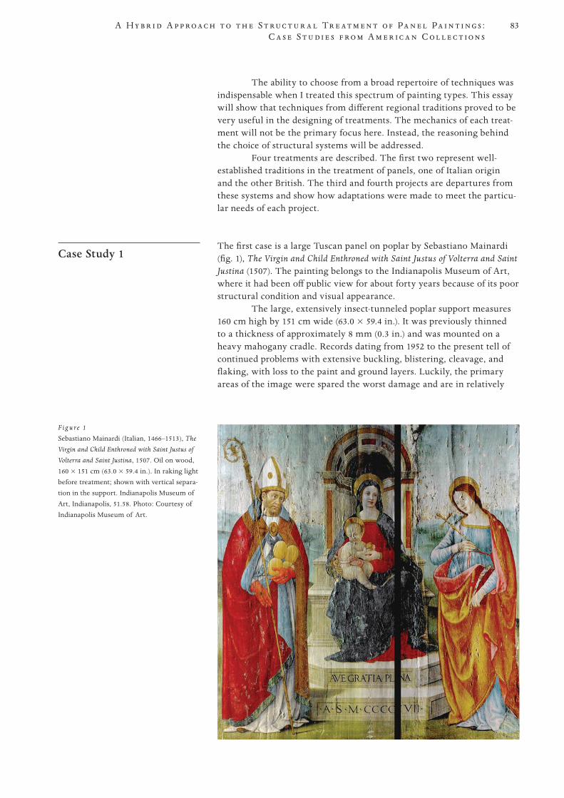
83
PROOF 1 2 3 4 5 6
A H y b r i d A p p r o a c h t o t h e S t r u c t u r a l Tr e a t m e n t o f Pa n e l Pa i n t i n g s : C a s e S t u d i e s f r o m A m e r i c a n C o l l e c t i o n s
The ability to choose from a broad repertoire of techniques was indispensable when I treated this spectrum of painting types. This essay will show that techniques from different regional traditions proved to be very useful in the designing of treatments. The mechanics of each treat-ment will not be the primary focus here. Instead, the reasoning behind the choice of structural systems will be addressed.
Four treatments are described. The first two represent well-established traditions in the treatment of panels, one of Italian origin and the other British. The third and fourth projects are departures from these systems and show how adaptations were made to meet the particu-lar needs of each project.
Case Study 1 The first case is a large Tuscan panel on poplar by Sebastiano Mainardi
(fig. 1), The Virgin and Child Enthroned with Saint Justus of Volterra and Saint Justina (1507). The painting belongs to the Indianapolis Museum of Art, where it had been off public view for about forty years because of its poor structural condition and visual appearance.
The large, extensively insect-tunneled poplar support measures 160 cm high by 151 cm wide (63.0 × 59.4 in.). It was previously thinned to a thickness of approximately 8 mm (0.3 in.) and was mounted on a heavy mahogany cradle. Records dating from 1952 to the present tell of continued problems with extensive buckling, blistering, cleavage, and flaking, with loss to the paint and ground layers. Luckily, the primary areas of the image were spared the worst damage and are in relatively
F ig u re 1
Sebastiano Mainardi (Italian, 1466–1513), The
Virgin and Child Enthroned with Saint Justus of
Volterra and Saint Justina, 1507. Oil on wood, 160 × 151 cm (63.0 × 59.4 in.). In raking light before treatment; shown with vertical separa-tion in the support. Indianapolis Museum of Art, Indianapolis, 51.58. Photo: Courtesy of Indianapolis Museum of Art.
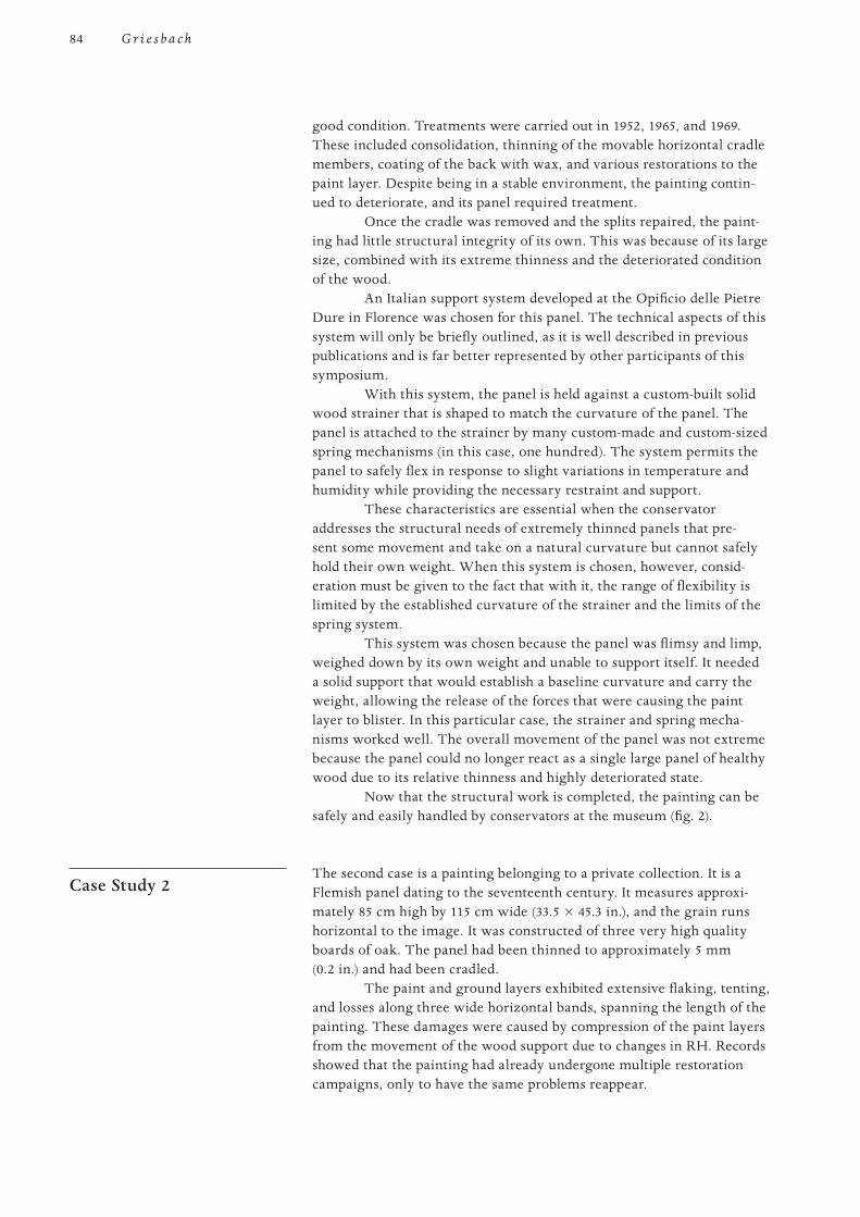
84
PROOF 1 2 3 4 5 6
G r i e s b a c h
good condition. Treatments were carried out in 1952, 1965, and 1969. These included consolidation, thinning of the movable horizontal cradle members, coating of the back with wax, and various restorations to the paint layer. Despite being in a stable environment, the painting contin-ued to deteriorate, and its panel required treatment.
Once the cradle was removed and the splits repaired, the paint-ing had little structural integrity of its own. This was because of its large size, combined with its extreme thinness and the deteriorated condition of the wood.
An Italian support system developed at the Opificio delle Pietre Dure in Florence was chosen for this panel. The technical aspects of this system will only be briefly outlined, as it is well described in previous publications and is far better represented by other participants of this symposium.
With this system, the panel is held against a custom-built solid wood strainer that is shaped to match the curvature of the panel. The panel is attached to the strainer by many custom-made and custom-sized spring mechanisms (in this case, one hundred). The system permits the panel to safely flex in response to slight variations in temperature and humidity while providing the necessary restraint and support.
These characteristics are essential when the conservator addresses the structural needs of extremely thinned panels that pre-sent some movement and take on a natural curvature but cannot safely hold their own weight. When this system is chosen, however, consid-eration must be given to the fact that with it, the range of flexibility is limited by the established curvature of the strainer and the limits of the spring system.
This system was chosen because the panel was flimsy and limp, weighed down by its own weight and unable to support itself. It needed a solid support that would establish a baseline curvature and carry the weight, allowing the release of the forces that were causing the paint layer to blister. In this particular case, the strainer and spring mecha-nisms worked well. The overall movement of the panel was not extreme because the panel could no longer react as a single large panel of healthy wood due to its relative thinness and highly deteriorated state.
Now that the structural work is completed, the painting can be safely and easily handled by conservators at the museum (fig. 2).
Case Study 2 The second case is a painting belonging to a private collection. It is a
Flemish panel dating to the seventeenth century. It measures approxi-mately 85 cm high by 115 cm wide (33.5 × 45.3 in.), and the grain runs horizontal to the image. It was constructed of three very high quality boards of oak. The panel had been thinned to approximately 5 mm (0.2 in.) and had been cradled.
The paint and ground layers exhibited extensive flaking, tenting, and losses along three wide horizontal bands, spanning the length of the painting. These damages were caused by compression of the paint layers from the movement of the wood support due to changes in RH. Records showed that the painting had already undergone multiple restoration campaigns, only to have the same problems reappear.
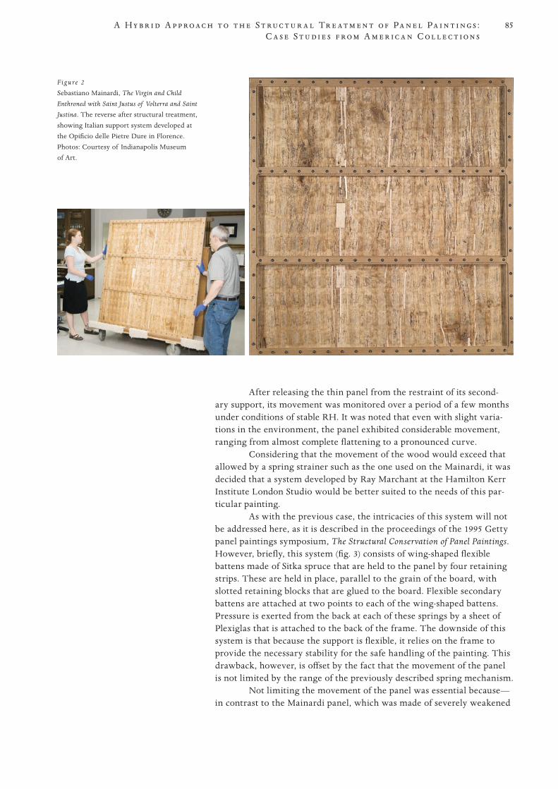
85
PROOF 1 2 3 4 5 6
A H y b r i d A p p r o a c h t o t h e S t r u c t u r a l Tr e a t m e n t o f Pa n e l Pa i n t i n g s : C a s e S t u d i e s f r o m A m e r i c a n C o l l e c t i o n s
After releasing the thin panel from the restraint of its second-ary support, its movement was monitored over a period of a few months under conditions of stable RH. It was noted that even with slight varia-tions in the environment, the panel exhibited considerable movement, ranging from almost complete flattening to a pronounced curve.
Considering that the movement of the wood would exceed that allowed by a spring strainer such as the one used on the Mainardi, it was decided that a system developed by Ray Marchant at the Hamilton Kerr Institute London Studio would be better suited to the needs of this par-ticular painting.
As with the previous case, the intricacies of this system will not be addressed here, as it is described in the proceedings of the 1995 Getty panel paintings symposium, The Structural Conservation of Panel Paintings. However, briefly, this system (fig. 3) consists of wing-shaped flexible battens made of Sitka spruce that are held to the panel by four retaining strips. These are held in place, parallel to the grain of the board, with slotted retaining blocks that are glued to the board. Flexible secondary battens are attached at two points to each of the wing-shaped battens. Pressure is exerted from the back at each of these springs by a sheet of Plexiglas that is attached to the back of the frame. The downside of this system is that because the support is flexible, it relies on the frame to provide the necessary stability for the safe handling of the painting. This drawback, however, is offset by the fact that the movement of the panel is not limited by the range of the previously described spring mechanism.
Not limiting the movement of the panel was essential because—in contrast to the Mainardi panel, which was made of severely weakened
Figure 2
Sebastiano Mainardi, The Virgin and Child
Enthroned with Saint Justus of Volterra and Saint
Justina. The reverse after structural treatment, showing Italian support system developed at the Opificio delle Pietre Dure in Florence. Photos: Courtesy of Indianapolis Museum of Art.
86
PROOF 1 2 3 4 5 6
G r i e s b a c h
poplar—the oak of the Flemish painting was strong and in beautiful con-dition, despite being flimsy and very thin. As such, the panel reacted to changes in RH as a single board with one homogeneous curve. The large size of the panel in combination with its thinness meant that the range of change in its curvature would be much greater than that of the Mainardi. This factor was especially relevant to this painting, as it belongs to a private collection and is unfortunately destined to be kept in a relatively uncontrolled environment, where it will be subjected to changes in RH.
The next two case studies are derivations from the support sys-tems discussed above. The purpose of including these is not to show new techniques but, rather, to illustrate how elements can be drawn from the other systems and tailored to suit the specific needs of a particular work of art. To define these needs, consideration is given not only to the physical qualities of the works of art but also to their context and their environment, as well as to the restraints and resources available to the conservator at the time of the treatment.
Case Study 3 This is a group of three curious small paintings by the American artist
Joseph Decker (fig. 4). They are roughly dated to between 1883 and 1885. The three are owned by a museum that wishes to remain anonymous. Once exhibited, all three paintings will be displayed together.
Each depicts the head of a young boy, mouth wide open, engaged in various activities. Their titles describe the activities: Boy at Dentist, Boy Eating Berries, and Boy Smoking. They are all painted on art-ist’s palettes.
The treatment of these paintings not only required the design of a support that would stabilize and preserve the structures but also presented an interesting challenge because of the unusual nature of the works. An important consideration in the design of the supports was to maintain the integrity of the palettes, not only as paintings but also as painted objects. The new support system therefore needed to be easily
Figure 3
Seventeenth-century Flemish oak panel. The reverse after structural treatment, showing system developed by Ray Marchant at the Hamilton Kerr Institute London Studio. Photo: Monica Griesbach.
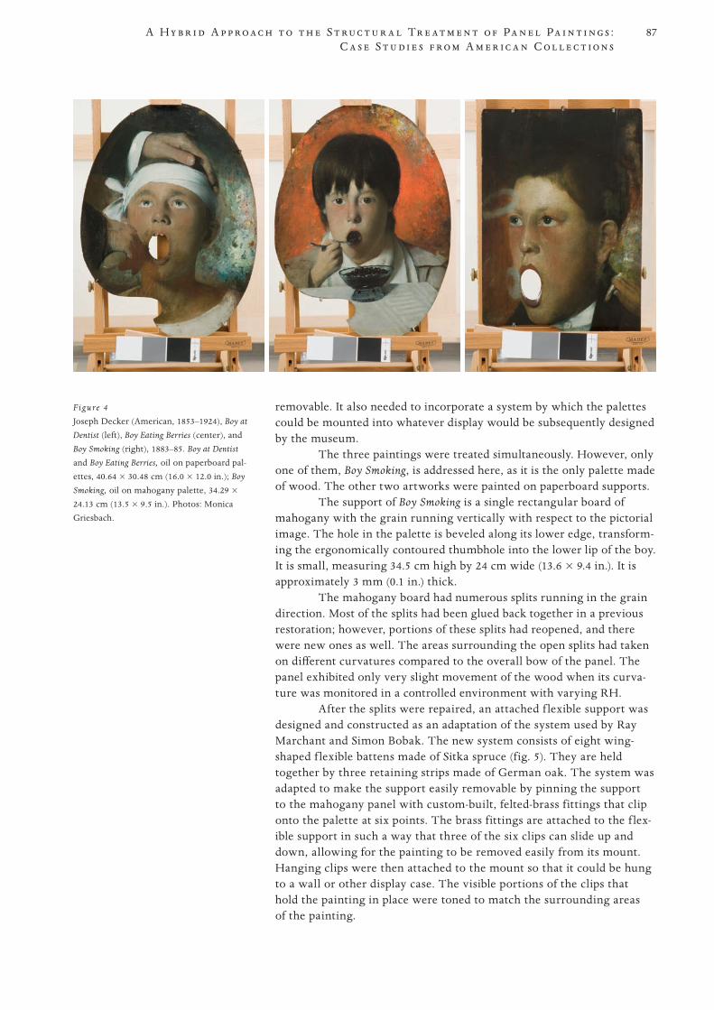
87
PROOF 1 2 3 4 5 6
A H y b r i d A p p r o a c h t o t h e S t r u c t u r a l Tr e a t m e n t o f Pa n e l Pa i n t i n g s : C a s e S t u d i e s f r o m A m e r i c a n C o l l e c t i o n s
removable. It also needed to incorporate a system by which the palettes could be mounted into whatever display would be subsequently designed by the museum.
The three paintings were treated simultaneously. However, only one of them, Boy Smoking, is addressed here, as it is the only palette made of wood. The other two artworks were painted on paperboard supports.
The support of Boy Smoking is a single rectangular board of mahogany with the grain running vertically with respect to the pictorial image. The hole in the palette is beveled along its lower edge, transform-ing the ergonomically contoured thumbhole into the lower lip of the boy. It is small, measuring 34.5 cm high by 24 cm wide (13.6 × 9.4 in.). It is approximately 3 mm (0.1 in.) thick.
The mahogany board had numerous splits running in the grain direction. Most of the splits had been glued back together in a previous restoration; however, portions of these splits had reopened, and there were new ones as well. The areas surrounding the open splits had taken on different curvatures compared to the overall bow of the panel. The panel exhibited only very slight movement of the wood when its curva-ture was monitored in a controlled environment with varying RH.
After the splits were repaired, an attached f lexible support was designed and constructed as an adaptation of the system used by Ray Marchant and Simon Bobak. The new system consists of eight wing-shaped f lexible battens made of Sitka spruce (fig. 5). They are held together by three retaining strips made of German oak. The system was adapted to make the support easily removable by pinning the support to the mahogany panel with custom-built, felted-brass fittings that clip onto the palette at six points. The brass fittings are attached to the f lex-ible support in such a way that three of the six clips can slide up and down, allowing for the painting to be removed easily from its mount. Hanging clips were then attached to the mount so that it could be hung to a wall or other display case. The visible portions of the clips that hold the painting in place were toned to match the surrounding areas of the painting.
Figure 4
Joseph Decker (American, 1853–1924), Boy at
Dentist (left), Boy Eating Berries (center), and
Boy Smoking (right), 1883–85. Boy at Dentist and Boy Eating Berries, oil on paperboard pal-ettes, 40.64 × 30.48 cm (16.0 × 12.0 in.); Boy
Smoking, oil on mahogany palette, 34.29 × 24.13 cm (13.5 × 9.5 in.). Photos: Monica Griesbach.
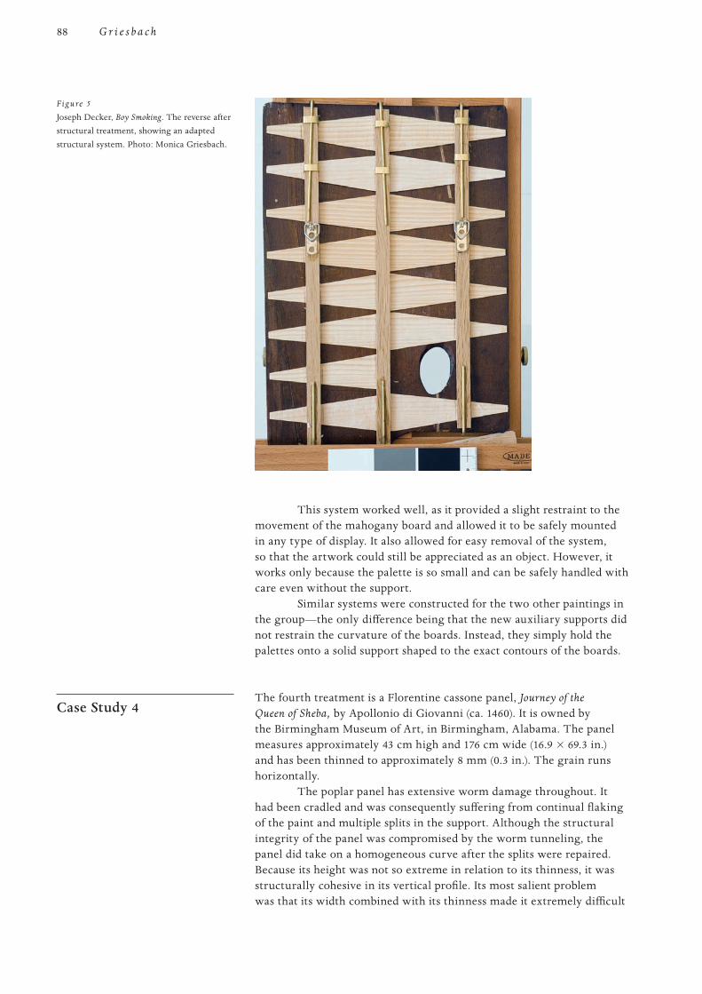
88
PROOF 1 2 3 4 5 6
G r i e s b a c h
This system worked well, as it provided a slight restraint to the movement of the mahogany board and allowed it to be safely mounted in any type of display. It also allowed for easy removal of the system, so that the artwork could still be appreciated as an object. However, it works only because the palette is so small and can be safely handled with care even without the support.
Similar systems were constructed for the two other paintings in the group—the only difference being that the new auxiliary supports did not restrain the curvature of the boards. Instead, they simply hold the palettes onto a solid support shaped to the exact contours of the boards.
Case Study 4 The fourth treatment is a Florentine cassone panel, Journey of the
Queen of Sheba, by Apollonio di Giovanni (ca. 1460). It is owned by the Birmingham Museum of Art, in Birmingham, Alabama. The panel measures approximately 43 cm high and 176 cm wide (16.9 × 69.3 in.) and has been thinned to approximately 8 mm (0.3 in.). The grain runs horizontally.
The poplar panel has extensive worm damage throughout. It had been cradled and was consequently suffering from continual flaking of the paint and multiple splits in the support. Although the structural integrity of the panel was compromised by the worm tunneling, the panel did take on a homogeneous curve after the splits were repaired. Because its height was not so extreme in relation to its thinness, it was structurally cohesive in its vertical profile. Its most salient problem was that its width combined with its thinness made it extremely difficult
Figure 5
Joseph Decker, Boy Smoking. The reverse after structural treatment, showing an adapted structural system. Photo: Monica Griesbach.
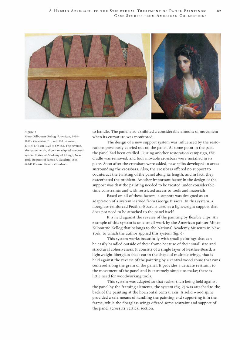
89
PROOF 1 2 3 4 5 6
A H y b r i d A p p r o a c h t o t h e S t r u c t u r a l Tr e a t m e n t o f Pa n e l Pa i n t i n g s : C a s e S t u d i e s f r o m A m e r i c a n C o l l e c t i o n s
to handle. The panel also exhibited a considerable amount of movement when its curvature was monitored.
The design of a new support system was influenced by the resto - rations previously carried out on the panel. At some point in the past, the panel had been cradled. During another restoration campaign, the cradle was removed, and four movable crossbars were installed in its place. Soon after the crossbars were added, new splits developed in areas surrounding the crossbars. Also, the crossbars offered no support to counteract the twisting of the panel along its length, and in fact, they exacerbated the problem. Another important factor in the design of the support was that the painting needed to be treated under considerable time constraints and with restricted access to tools and materials.
Based on all of these factors, a support was designed as an adaptation of a system learned from George Bisacca. In this system, a fiberglass-reinforced Feather-Board is used as a lightweight support that does not need to be attached to the panel itself.
It is held against the reverse of the painting by flexible clips. An example of this system is on a small work by the American painter Miner Kilbourne Kellog that belongs to the National Academy Museum in New York, to which the author applied this system (fig. 6).
This system works beautifully with small paintings that can be easily handled outside of their frame because of their small size and structural cohesiveness. It consists of a single layer of Feather-Board, a lightweight fiberglass sheet cut in the shape of multiple wings, that is held against the reverse of the painting by a central wood spine that runs centered along the grain of the panel. It provides a delicate restraint to the movement of the panel and is extremely simple to make; there is little need for woodworking tools.
This system was adapted so that rather than being held against the panel by the framing elements, the system (fig. 7) was attached to the back of the painting at the horizontal central axis. A solid wood spine provided a safe means of handling the painting and supporting it in the frame, while the fiberglass wings offered some restraint and support of the panel across its vertical section.
Figure 6
Miner Kilbourne Kellog (American, 1814–1889), Circassian Girl, n.d. Oil on wood, 23.5 × 17.5 cm (9.25 × 6.9 in.). The reverse, after panel work, shows an adapted structural system. National Academy of Design, New York, Bequest of James A. Suydam, 1865, 692-P. Photos: Monica Griesbach.
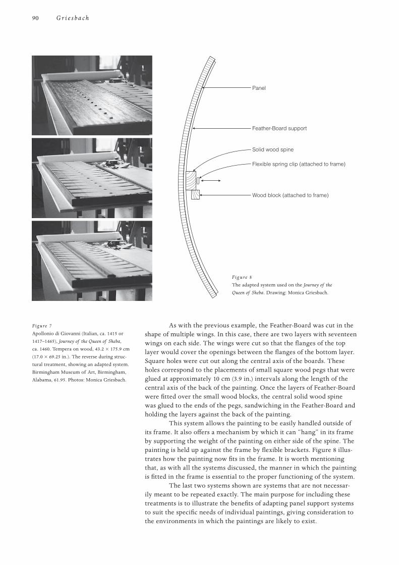
90
PROOF 1 2 3 4 5 6
G r i e s b a c h
As with the previous example, the Feather-Board was cut in the shape of multiple wings. In this case, there are two layers with seventeen wings on each side. The wings were cut so that the flanges of the top layer would cover the openings between the flanges of the bottom layer. Square holes were cut out along the central axis of the boards. These holes correspond to the placements of small square wood pegs that were glued at approximately 10 cm (3.9 in.) intervals along the length of the central axis of the back of the painting. Once the layers of Feather-Board were fitted over the small wood blocks, the central solid wood spine was glued to the ends of the pegs, sandwiching in the Feather-Board and holding the layers against the back of the painting.
This system allows the painting to be easily handled outside of its frame. It also offers a mechanism by which it can “hang” in its frame by supporting the weight of the painting on either side of the spine. The painting is held up against the frame by flexible brackets. Figure 8 illus-trates how the painting now fits in the frame. It is worth mentioning that, as with all the systems discussed, the manner in which the painting is fitted in the frame is essential to the proper functioning of the system.
The last two systems shown are systems that are not necessar-ily meant to be repeated exactly. The main purpose for including these treatments is to illustrate the benefits of adapting panel support systems to suit the specific needs of individual paintings, giving consideration to the environments in which the paintings are likely to exist.
Flexible spring clip (attached to frame)
Wood block (attached to frame)
Solid wood spine
Feather-Board support
Panel
Figure 7
Apollonio di Giovanni (Italian, ca. 1415 or 1417–1465), Journey of the Queen of Sheba, ca. 1460. Tempera on wood, 43.2 × 175.9 cm (17.0 × 69.25 in.). The reverse during struc-tural treatment, showing an adapted system. Birmingham Museum of Art, Birmingham, Alabama, 61.95. Photos: Monica Griesbach.
F ig u re 8
The adapted system used on the Journey of the
Queen of Sheba. Drawing: Monica Griesbach.
91
PROOF 1 2 3 4 5 6
A H y b r i d A p p r o a c h t o t h e S t r u c t u r a l Tr e a t m e n t o f Pa n e l Pa i n t i n g s : C a s e S t u d i e s f r o m A m e r i c a n C o l l e c t i o n s
Conclusion Choosing to specialize in the field of structural work on panel paintings,
particularly when educated in the United States where the specialty is notably absent in the training programs, requires that conservators in training be resourceful and creative in acquiring practical experience. It usually requires that they seek out panel paintings conservators in other countries in order to acquire the essential skills and knowledge for prac-tice. Such training provides valuable opportunities to observe and learn from the numerous and varied regional approaches.
Knowledge of a broad range of techniques was essential in designing the structural systems shown. Furthermore, working in private practice, the conservator often faces inevitable challenges brought about by constraints that are outside of the strictly physical requirements of the work of art. Having a wide vocabulary to draw from enables the conser-vator to be equipped to improvise in an effective and responsible way, addressing the needs of each painting on a case-by-case basis.
For the author, working in such a way would not have been pos-sible without having been fortunate enough to have worked with and learned from some of the best experts in our field. Further opportunities for exchanges in techniques and approaches, such as that provided by this symposium, can only increase the technical vocabulary available to those working in this field.
Materials and Suppliers Feather-Board, a fiberglass-reinforced material made in Sweden, imported by Danoka
International (sole U.S. importer), PO Box 564, Mound, MN 55364, USA.


![The sufficiency of the minimum amounts in compulsory ... 4 2015/WU 2015-04 07... · M. Monkiewicz, Regulacyjna baza jednolitego rynku ubezpieczeń Unii …uropejskiej, [w:] Jednolity](https://img.dokumen.tips/doc/110x75/5c78b6e309d3f2fb438bd1f3/the-sufficiency-of-the-minimum-amounts-in-compulsory-4-2015wu-2015-04-07.jpg)