Embed Size (px)
Citation preview

Page 1
FAB22938
Create Structural Shop Drawings for Concrete, Precast, and Steel Structures in Revit Dan McCloskey, P.E. MB BIM Solutions Erich Bretz, P.E. MB BIM Solutions
Description
With the new tools added to Revit software in the last few years, it has become easier for structural engineers and detailers to create shop drawings and fabrication models for structural components. This class will demonstrate Building Information Modeling (BIM) workflows to take a Structural Design Team model into fabrication modeling and shop-drawings production for rebar, precast-concrete, structural-steel, and concrete-lift drawings. Attendees will learn new rebar modeling and annotation features for rebar shop-drawing creation. They will also learn how the new steel-connections tool works in Revit 2017 software and links with Advance Steel software; how to create precast-concrete erection (shop) and piece drawings in Revit software; and how to create detailed concrete-lift drawings in Revit software. We will also demonstrate add-ons that make shop-drawing production more efficient for each structural component type, and we’ll discuss workflows and best practices. This session features Revit Structure and Advance Steel.
Your AU Expert(s)
Dan McCloskey received his bachelor's degree in civil engineering from the University of Illinois at Champaign-Urbana. After spending 2 years designing bridges for URS Corporation, McCloskey attended Purdue University, where he obtained a master’s degree in structural engineering. McCloskey then moved to Denver, Colorado, where he worked as a structural design engineer and then structural project engineer for S.A. Miro. During his 5 years with Miro, McCloskey became an in-house expert in Revit Structure software, and he helped develop
Learning Objectives
• Learn how rebar shops drawings can be created within Revit, and discover the new tools for rebar modeling and annotation
• See families and workflows that enable precast-concrete fabricators to create erection and piece drawings in Revit
• Learn how to create concrete-lift drawings in Revit to enhance coordination and improve field productivity
• Discover new steel connection tools in Revit 2017—and learn how to create steel shops in Revit and Advance Steel

Page 2
Building Information Modeling (BIM)-based structural detailing services. In 2011, McCloskey co-founded MB BIM Solutions as a BIM-focused consultancy that provides construction-level modeling of structural systems and components for its clients. McCloskey is active in the Denver-area BIM community with Rocky Mountain Building Information Society, has taught several classes at Autodesk University, has been published in AUGIWorld magazine, is a Revit Beta contributor, and is also a Revit Gunslinger participant. Erich Bretz's ability to quickly and effectively solve engineering challenges has given him the opportunity to work on a wide range of construction projects including healthcare, educational, institutional, multifamily residential, resort, office, and retail projects. In the recent past, he has established himself as a leader in Building Information Modeling (BIM) and virtual design and construction (VDC) technology. His extensive knowledge of these technologies has given him the opportunity to bring real value to owners, general contractors, fabricators, architects, and engineers on many projects. Bretz holds a BS in civil engineering with a minor in computer science, and an MS in structural engineering, all from the University of Illinois.
Page 3
Introduction
Due to new tools available to design teams and contractors, faster construction schedules, and the increased in integrated project delivery through the use of BIM, the ‘who’, ‘how’, and ‘when’ of shop drawings and fabrication models is changing. It is now possible to leverage a structural engineer’s design model to create shops drawings and fabrication models for rebar, precast, structural steel and miscellaneous metals, and to create concrete lift drawings. The ‘who’ is starting to change from fabricators and subcontractors to structural engineers, and BIM consultants. The ‘how’ is changing from 2D CAD for rebar, concrete lift drawings, and precast concrete, and from Tekla and SDS/2 for steel. Revit (and Advance Steel) can now be used to do this on a true BIM platform, with the advantage being to re-use the information and knowledge in a design Revit model further downstream into fabrication and construction. The ‘when’ is being change from a linear design-bid-build structure to a collaborative structure in which shop drawings and piece drawings are being produced in the late stages of the design process. This new approach enables schedule and constructability efficiencies by engaging the fabrication and construction team’s knowledge and preferences before design is complete.
General Who/When/Why/How
The goal of this class is to provide an introduction on how to create shop drawings for structural elements using Revit, and will focus on the how rather than the why. For in-depth information on the business insight of this topic, please see FAB20958 - Structural Detailing Services by Structural Engineers – Who, How, When, and Why? In general, making the switch from traditional shop drawings and fabrication level drawing to using BIM to create these drawings has an effect on how the process works from start to finish. BIM can be used by engineers and BIM consultants to create fabrication level drawings for rebar, precast, structural steel and concrete lift drawings.
Who (and Why)? Making the switch from fabricators to BIM consultants and engineers to create fabrication drawing affects many different entities in different ways. As outlined below, the process is much more collaborative with each member to the team having a seat at the table early in the process.
Design Team Because of the collaborative nature, using BIM for fabrication drawings presents less risk to the design team, yields a higher quality product and creates less adverse relationships with the construction team.
Fabricators and Subcontractors The drawing quality and coordination level is improved through the use of BIM resulting in more efficiency and accuracy for fabricators and subcontractors.
General Contractors Having a seat at the table early in design, general contractors are able to influence design decisions. This, along with the better drawing quality provides less risk and less waste for the GC.
Page 4
Owners Owners will see a better product with less change orders, faster scheduled and lower overall cost through the use of BIM for fabrication drawing.
When? Making the decision to switch from fabricators to BIM consultants or engineers to create fabrication drawing needs to be made as early as possible. As outlined above, having all parties at the table early on is an important step in the process. However, depending on the service offered, the exact ‘when’ can vary. Having the process implemented early in design allows the GC to begin construction planning early. The models can be used early in design to assign data, estimate quantities and plan construction activities. These models can then be fine-tuned and taken to fabrication level models used to produce drawings.
Why (and why not)? With construction schedules getting faster and owners wanting ‘more bang for their buck’, BIM-produced fabrication drawings can be used to expedite the process with a higher quality product. However, there are cons to using BIM produced fabrication drawings.
Advantages In general, using BIM to produce fabrication drawings yields a higher quality product, a faster schedule, less field issues, more accurate drawings, field efficiencies, material savings and more available data.
Disadvantages Using BIM to produce fabrication drawings doesn’t make sense for every job. And using BIM to produce fabrication drawings vs. the traditional process requires a change in mentalities. This process requires more communication; the roles are less defined and there is a change in risk structure.
How? The focus of this class will be on the how of using Revit to create shop drawings for structural elements. We will cover rebar, concrete lift drawings, structural steel, and precast concrete.
Rebar Modeling and Shop Drawings in Revit
Why (and When) to Model Rebar
Modeling rebar for an entire building is very time intensive and takes considerable effort. Modeling rebar for the sole purpose of meeting an arbitrary BIM LOD (level of detail) requirement is not recommended, unless that rebar model is going to be pushed downstream into fabrication/construction and used to save schedule or money.
Why/When to Model Rebar • Shop drawing production
o Why – construction schedule and material tonnage ($$) savings • Constructability, congestion, and coordination studies
o Why – better constructability, reduced congestion issues, enhanced coordination
Why/When NOT to Model Rebar • Because you can
o Why not – you’ll blow your budget
Page 5
• To draw details for construction documents o Why not – you’ll end up chasing around bar in other unrelated views,
modifications are more of a pain, and you can draw details faster using detail components
General Considerations for Starting the Model One of the first things to consider, in the case of a structural engineer acting as EOR for a project and simultaneously creating a rebar model and shop drawings, is whether to combine the rebar and design models, or create two separate models. We prefer to have two separate models, which are obviously then linked and copy/monitored. Here are the pros and cons of the separate model approach:
Pros:
• Design modeling vs. construction modeling – different needs and LOD • File size – these models can get very big, and tougher to work with for the design
team • Possibility of design team inadvertently messing up rebar
Cons: • Duplication of work, possibility of design model not matching rebar model • Some data and details will need to be generated twice
It may make sense to combine the design and rebar model for some firms or for specific projects. In this case, using worksets is a good way to separate the rebar from the rest of the model. Before starting on a rebar model, we recommend meeting with the fabricator, installer, and GC (or concrete sub) to kick off the project and determine pour breaks, bar lengths, installation preferences, BOM data preferences, etc.. Multiple Rebar Models? Another thing to consider is whether or not the project justifies the use of multiple rebar models. This may seem counterintuitive from a workflow, model management, and bar numbering standpoint. However, the bar numbering problem can be easily solved by using partitions that are created to work across different models.
Pros:
• Lighter models • Avoid unintentional interaction between rebar of different element type, like
columns and slabs Cons:
• If using these models in Navisworks or as linked models, more models to manage
• Need to jump between models to modify different bar in an area where bar from the different models interacts (i.e. core wall dowels and core wall verticals)

Page 6
FIGURE 1: FOUR REBAR MODELS LINKED TOGETHER, COLOR-CODED BY MODEL
For a large (2000 ton) rebar modeling project, we had three main models. Figure 1 shows the foundation model in green, the walls/columns model in blue and the slab in red. The main driving force to our decision to use multiple models was model weight and concern that a user could inadvertently modify rebar in one element by adjusting rebar in another element. Rebar Parameter Management When setting up and managing parameters in a large Revit rebar model, it is a good idea to take a step back and think about how to best organize these parameters. The goal should be to use the fewest number of parameters possible, and have those parameters be used across a multitude of tools and processes:
• Sheet / view visibilities / filters • Bend schedules and bills of material (BOM’s) • Tags • Assemblies • QC • Bar marking and numbering
Parameters Used We use the following parameters for the following purposes. We try to minimize the number of parameters to keep the system simple for users, but also flexible across our processes:

Page 7
FIGURE 2: REBAR INSTANCE PARAMETERS
Partition: This is the parameter from which automatic bar numbering in Revit is set. For each partition, Revit will find identical rebar and assign the same rebar number. Therefore, this parameter is extremely important in managing and defining your bar marking and numbering system. Possible uses of the partition parameter are to organize the rebar numbering scheme in your model by construction sequencing and phasing (pours), host element types, location within a host (i.e. top and bottom bar), or location in the model. For 17W and on most jobs, we use the partition to signify the element type from which the rebar is hosted (i.e. caisson, mat slabs, columns, walls, slabs, etc.), and poured as one. This way, a typical 4L0254 slab edge rebar (‘candy-cane’ bar) at Level 5 has the same bar mark as the identical bar at Level 11, even though they are in different pours. Then our client can steal bars from different deliveries as needed, and their rod-busters are placing consistent bar marks on repetitive jobs. Another thing we do with our partitions is to use an ‘S’ suffix for straight bar of the same element type, since straight bar doesn’t typically have a bar mark. For example, all slab rebar has partition ‘L’ or ‘LS’. This allows us to filter straight bar out of bend schedule, have different tags for straight or bent bar, and use partition filters that use ‘contains L’. This also helps us to easily QC the partition within the data. Rebar Number:
Page 8
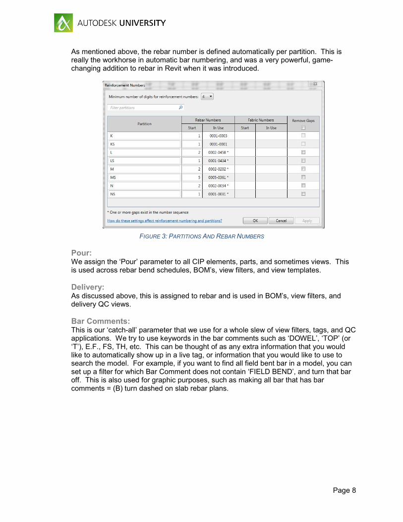
As mentioned above, the rebar number is defined automatically per partition. This is really the workhorse in automatic bar numbering, and was a very powerful, game-changing addition to rebar in Revit when it was introduced.
FIGURE 3: PARTITIONS AND REBAR NUMBERS
Pour: We assign the ‘Pour’ parameter to all CIP elements, parts, and sometimes views. This is used across rebar bend schedules, BOM’s, view filters, and view templates. Delivery: As discussed above, this is assigned to rebar and is used in BOM’s, view filters, and delivery QC views. Bar Comments: This is our ‘catch-all’ parameter that we use for a whole slew of view filters, tags, and QC applications. We try to use keywords in the bar comments such as ‘DOWEL’, ‘TOP’ (or ‘T’), E.F., FS, TH, etc. This can be thought of as any extra information that you would like to automatically show up in a live tag, or information that you would like to use to search the model. For example, if you want to find all field bent bar in a model, you can set up a filter for which Bar Comment does not contain ‘FIELD BEND’, and turn that bar off. This is also used for graphic purposes, such as making all bar that has bar comments = (B) turn dashed on slab rebar plans.
Page 9
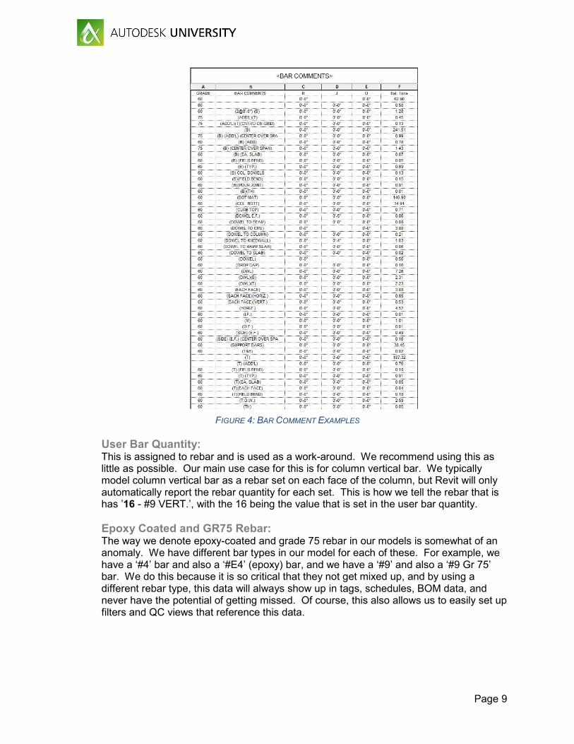
FIGURE 4: BAR COMMENT EXAMPLES
User Bar Quantity: This is assigned to rebar and is used as a work-around. We recommend using this as little as possible. Our main use case for this is for column vertical bar. We typically model column vertical bar as a rebar set on each face of the column, but Revit will only automatically report the rebar quantity for each set. This is how we tell the rebar that is has ’16 - #9 VERT.’, with the 16 being the value that is set in the user bar quantity. Epoxy Coated and GR75 Rebar: The way we denote epoxy-coated and grade 75 rebar in our models is somewhat of an anomaly. We have different bar types in our model for each of these. For example, we have a ‘#4’ bar and also a ‘#E4’ (epoxy) bar, and we have a ‘#9’ and also a ‘#9 Gr 75’ bar. We do this because it is so critical that they not get mixed up, and by using a different rebar type, this data will always show up in tags, schedules, BOM data, and never have the potential of getting missed. Of course, this also allows us to easily set up filters and QC views that reference this data.
Page 10
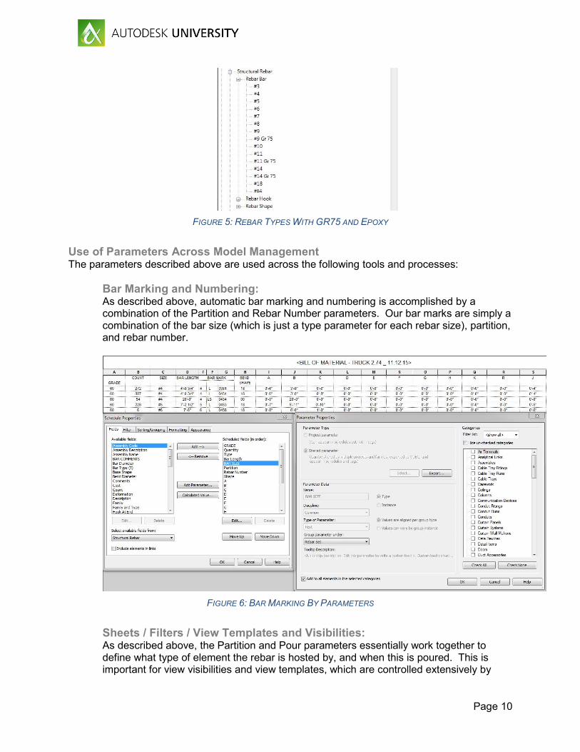
FIGURE 5: REBAR TYPES WITH GR75 AND EPOXY
Use of Parameters Across Model Management The parameters described above are used across the following tools and processes:
Bar Marking and Numbering: As described above, automatic bar marking and numbering is accomplished by a combination of the Partition and Rebar Number parameters. Our bar marks are simply a combination of the bar size (which is just a type parameter for each rebar size), partition, and rebar number.
FIGURE 6: BAR MARKING BY PARAMETERS
Sheets / Filters / View Templates and Visibilities: As described above, the Partition and Pour parameters essentially work together to define what type of element the rebar is hosted by, and when this is poured. This is important for view visibilities and view templates, which are controlled extensively by

Page 11
filters. For example, you usually don’t want your rebar shops to show concrete elements that will not be formed at the time of rebar placement. For something like slab rebar shops, you probably won’t want to see column rebar, so you can easily use a filter to turn off the partition that contains all column rebar. Bend Schedules and BOM’s: BOM’s are filtered down to only a specific ‘Delivery’ data input, but bend schedules use a combination of parameters to filter the bar data down to only what we want to see on a specific sheet. We use Partition, Pour, and Grade to filter down our bend schedules to only show the rebar that appears on specific sheets. Tags: We have found it best to keep our tagging scheme as simple as possible, and not let users create new tags for any new use case they come across. Our tags only contain bar quantity, ‘type name’ (bar size), bar length (for straight bar) or bar mark for bent bar, spacing, and bar comments. We do have different tags for where the ‘break’ is shown in the tag, and for bent bar vs. straight bar.
FIGURE 7: REBAR TAG OPTIONS
QC Views and QC Schedules: The use of the parameters described above in QC view and QC schedules is endless. We use a variety of filters to isolate only certain properties of bar (such as its placement in a slab, its size, grade, etc.), and then often assign color to those filters to make the QC process of a model with tens of thousands of pieces or rebar much more manageable.
New Rebar Tools in Revit 2017 With each new release of Revit, Autodesk continues to add to and enhance the tools available for rebar modeling and annotation. In Revit 2017, these tools are geared towards the modeling side.

Page 12
Reinforcement Connectors We are now able to model and document reinforcement connectors, such as formsavers and couplers, natively in Revit. These have properties similar to that of rebar, in that they are able to be scheduled, assembled, and tagged. They host to the ends of rebar, and correctly adjust the rebar ends to shorten as needed.
Variable Rebar Distribution We can now use rebar sets that vary along inclined faces of non-standard concrete elements. For us, this makes reinforcing and annotating the stirrups in a tapered beam much easier. Previously, we had to manually adjust the stirrups to increase their depth throughout the beam, but this new tools creates a rebar set for these stirrups. The annotation of this is also easier with this new tool. You have the option to assign a unique number to each of these stirrups, or you can make them the same number and have a suffix added to each different depth of stirrup.
Rebar Constraints Enhancements In previous releases of Revit, getting rebar to host within a concrete element where you want it sometimes was a struggle, partly due to the clunky rebar constraints dialogue box. In Revit 2017, the user now has a bit more control over the rebar’s behavior within the concrete element. In the new release, Revit still has the ability to adjust rebar locations as the concrete geometry changes. However, now the user can graphically see which concrete faces (or other rebar) the selected rebar is constrained to, adjust the target (graphically), and adjust the distance from the target. This can be done with all segments of a piece (or set) of rebar, giving the user much more control over rebar placement.
Creating Cast-in-Place Concrete Lift Drawings in Revit Several larger GC’s that self-perform their CIP concrete work has begun to use a model to create concrete lift drawings, and in the last couple of years we have done this more and more for our GC and concrete subcontractor clients. These are the benefits that we are seeing:
• Enhance productivity from field crews: o Much is a result of enhanced coordination (below), but it is also the result of
having clear, concise drawings with dimensions laid out in a manner consistent with how tape is laid out in the field.
o Isometrics of each pour that allow for field labor visualization of complicated pour geometry, and QC that all embedded items are included.
• Sharing of the model, pours, and drawings (often to DWG) to the formwork team and rebar detailing team. This ensures everyone is using the same information.
• Enhanced coordination: o By included all cast-in elements as well as void forms, wall pours are figured out
well ahead of time and contain all elements and data in one place. o Field crews do not have to look through design drawings and steel shops
drawings. Concrete lift drawings from the model contain everything shown in the drawings from all disciplines, as well as embeds.
• Quantity management (embeds, CIP pour volumes), schedule visualization and crew visualizations.
Page 13
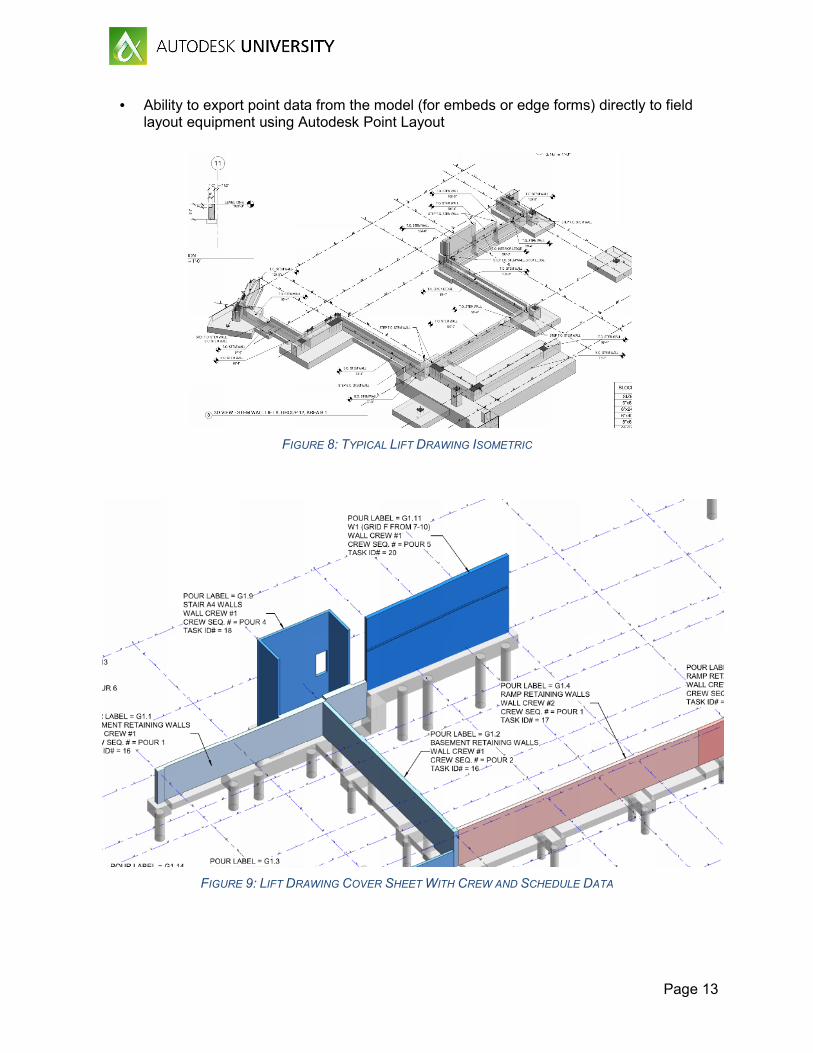
• Ability to export point data from the model (for embeds or edge forms) directly to field layout equipment using Autodesk Point Layout
FIGURE 8: TYPICAL LIFT DRAWING ISOMETRIC
FIGURE 9: LIFT DRAWING COVER SHEET WITH CREW AND SCHEDULE DATA
Page 14
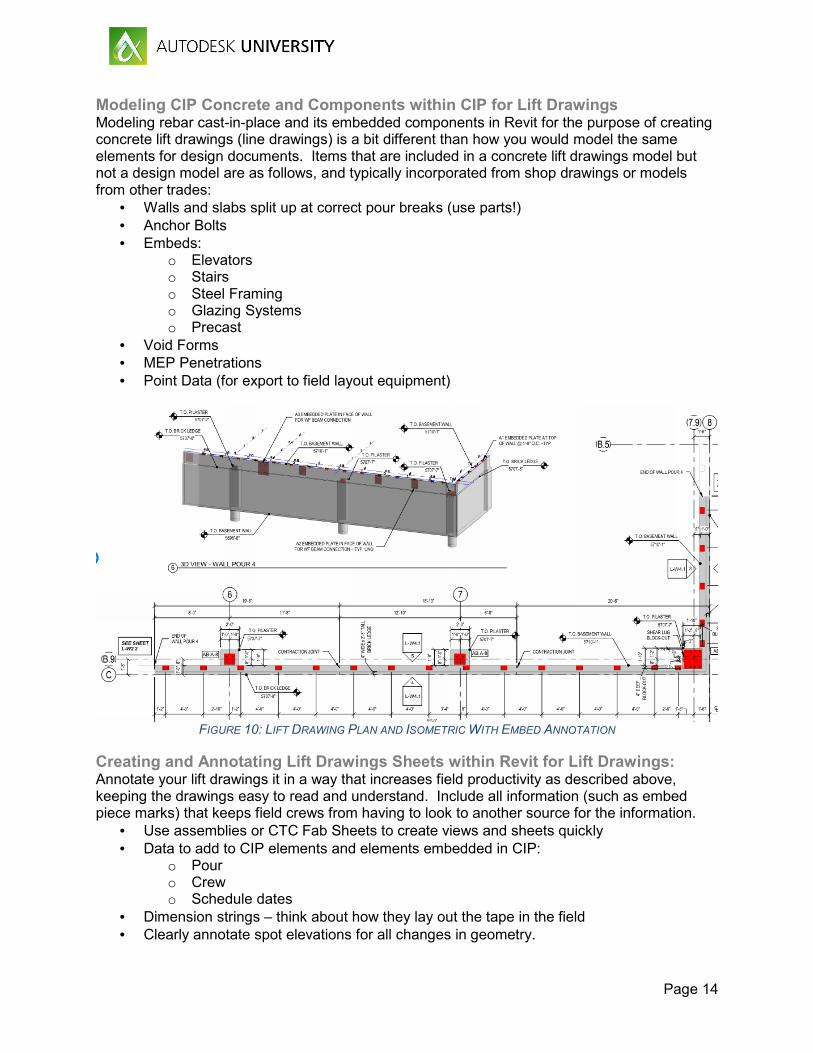
Modeling CIP Concrete and Components within CIP for Lift Drawings Modeling rebar cast-in-place and its embedded components in Revit for the purpose of creating concrete lift drawings (line drawings) is a bit different than how you would model the same elements for design documents. Items that are included in a concrete lift drawings model but not a design model are as follows, and typically incorporated from shop drawings or models from other trades:
• Walls and slabs split up at correct pour breaks (use parts!) • Anchor Bolts • Embeds:
o Elevators o Stairs o Steel Framing o Glazing Systems o Precast
• Void Forms • MEP Penetrations • Point Data (for export to field layout equipment)
FIGURE 10: LIFT DRAWING PLAN AND ISOMETRIC WITH EMBED ANNOTATION
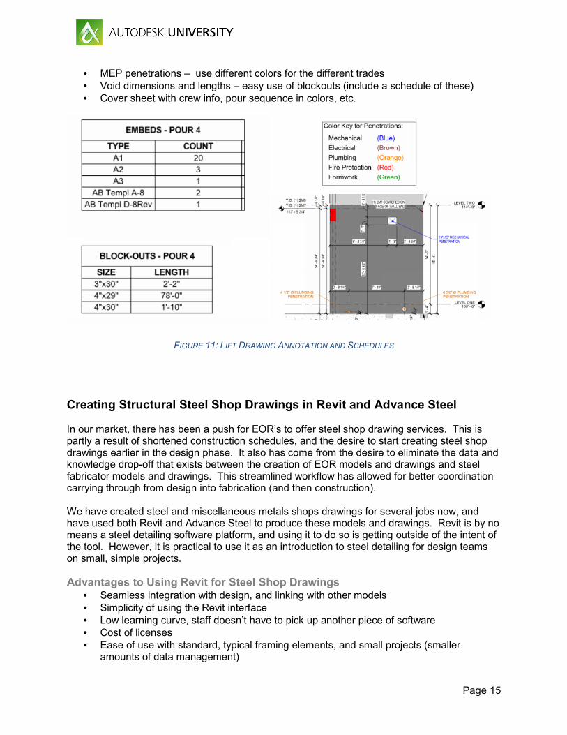
Creating and Annotating Lift Drawings Sheets within Revit for Lift Drawings: Annotate your lift drawings it in a way that increases field productivity as described above, keeping the drawings easy to read and understand. Include all information (such as embed piece marks) that keeps field crews from having to look to another source for the information.
• Use assemblies or CTC Fab Sheets to create views and sheets quickly • Data to add to CIP elements and elements embedded in CIP:
o Pour o Crew o Schedule dates
• Dimension strings – think about how they lay out the tape in the field • Clearly annotate spot elevations for all changes in geometry.
Page 15
• MEP penetrations – use different colors for the different trades • Void dimensions and lengths – easy use of blockouts (include a schedule of these) • Cover sheet with crew info, pour sequence in colors, etc.
FIGURE 11: LIFT DRAWING ANNOTATION AND SCHEDULES
Creating Structural Steel Shop Drawings in Revit and Advance Steel In our market, there has been a push for EOR’s to offer steel shop drawing services. This is partly a result of shortened construction schedules, and the desire to start creating steel shop drawings earlier in the design phase. It also has come from the desire to eliminate the data and knowledge drop-off that exists between the creation of EOR models and drawings and steel fabricator models and drawings. This streamlined workflow has allowed for better coordination carrying through from design into fabrication (and then construction). We have created steel and miscellaneous metals shops drawings for several jobs now, and have used both Revit and Advance Steel to produce these models and drawings. Revit is by no means a steel detailing software platform, and using it to do so is getting outside of the intent of the tool. However, it is practical to use it as an introduction to steel detailing for design teams on small, simple projects. Advantages to Using Revit for Steel Shop Drawings
• Seamless integration with design, and linking with other models • Simplicity of using the Revit interface • Low learning curve, staff doesn’t have to pick up another piece of software • Cost of licenses • Ease of use with standard, typical framing elements, and small projects (smaller
amounts of data management)
Page 16
• Ability to share models with steel fabricators that are utilizing Advance Steel and to receive models back from Advance Steel
Disadvantages to Using Revit for Steel Shop Drawings • Steel connections cannot be added to Revit assemblies • Schedules created in Revit assemblies are limited in their customization and the
parameters that can be added to them • There is no great way in Revit to create a ‘single part’ sheet for any single item • Assemblies in Revit are not very good at knowing when they are duplicates of existing
assemblies and when a new assembly type must be created. There are no tools to identify the differences between two seeming similar pieces. This functionality exists in Advance Steel and is very important.
• Lack of automation of piece drawings – no ability to automate dimensioning, piece marking, any other tools typical found in steel detailing software
• Inability to produce CNC output – this is HUGE and limits this to projects with smaller, less sophisticated fabricators
• Need to create families and connection elements manually with more complex families, while in steel detailing software this can be done out of the box
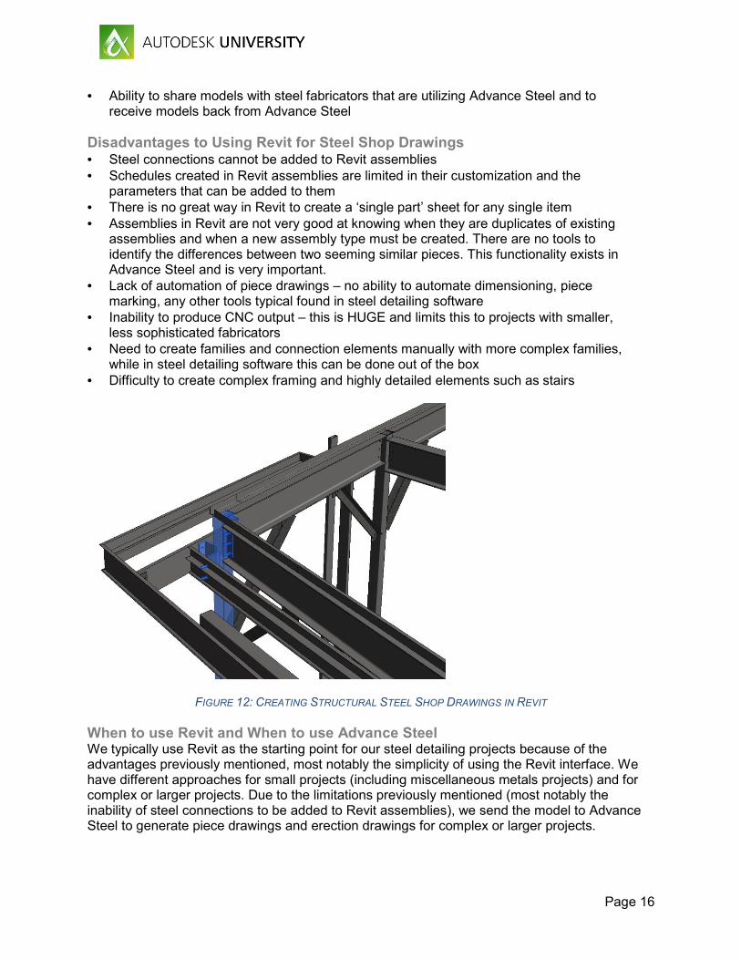
• Difficulty to create complex framing and highly detailed elements such as stairs
FIGURE 12: CREATING STRUCTURAL STEEL SHOP DRAWINGS IN REVIT
When to use Revit and When to use Advance Steel We typically use Revit as the starting point for our steel detailing projects because of the advantages previously mentioned, most notably the simplicity of using the Revit interface. We have different approaches for small projects (including miscellaneous metals projects) and for complex or larger projects. Due to the limitations previously mentioned (most notably the inability of steel connections to be added to Revit assemblies), we send the model to Advance Steel to generate piece drawings and erection drawings for complex or larger projects.
Page 17
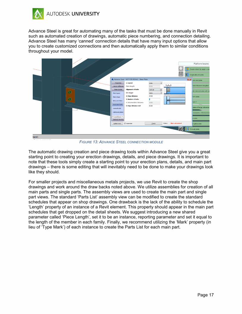
Advance Steel is great for automating many of the tasks that must be done manually in Revit such as automated creation of drawings, automatic piece numbering, and connection detailing. Advance Steel has many ‘canned’ connection details that have many input options that allow you to create customized connections and then automatically apply them to similar conditions throughout your model.
FIGURE 13: ADVANCE STEEL CONNECTION MODULE
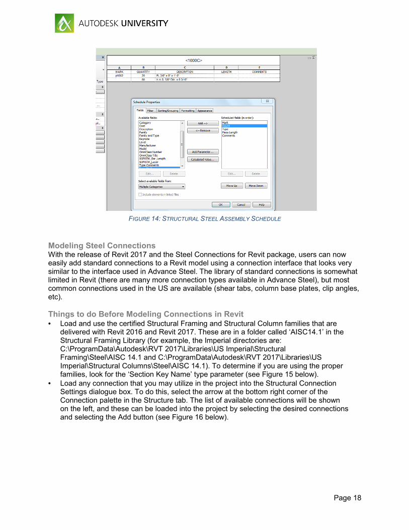
The automatic drawing creation and piece drawing tools within Advance Steel give you a great starting point to creating your erection drawings, details, and piece drawings. It is important to note that these tools simply create a starting point to your erection plans, details, and main part drawings – there is some editing that will inevitably need to be done to make your drawings look like they should. For smaller projects and miscellaneous metals projects, we use Revit to create the shop drawings and work around the draw backs noted above. We utilize assemblies for creation of all main parts and single parts. The assembly views are used to create the main part and single part views. The standard ‘Parts List’ assembly view can be modified to create the standard schedules that appear on shop drawings. One drawback is the lack of the ability to schedule the ‘Length’ property of an instance of a Revit element. This property should appear in the main part schedules that get dropped on the detail sheets. We suggest introducing a new shared parameter called ‘Piece Length’, set it to be an instance, reporting parameter and set it equal to the length of the member in each family. Finally, we recommend utilizing the ‘Mark’ property (in lieu of ‘Type Mark’) of each instance to create the Parts List for each main part.
Page 18
FIGURE 14: STRUCTURAL STEEL ASSEMBLY SCHEDULE
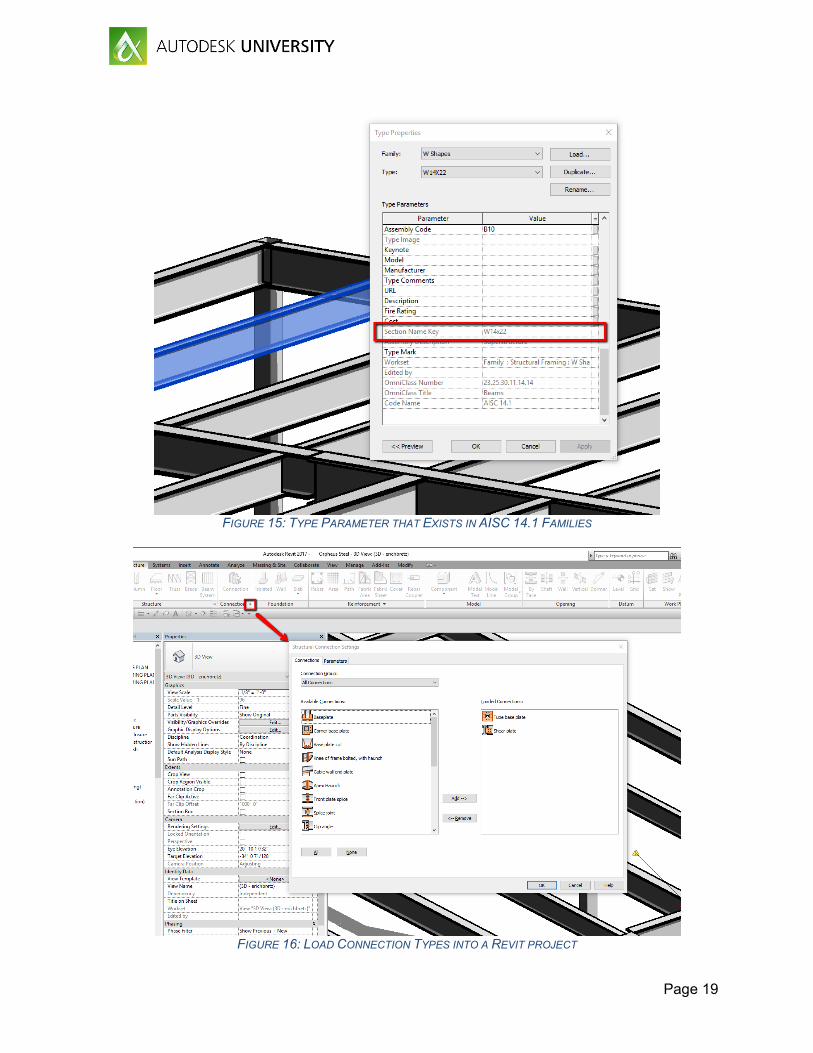
Modeling Steel Connections With the release of Revit 2017 and the Steel Connections for Revit package, users can now easily add standard connections to a Revit model using a connection interface that looks very similar to the interface used in Advance Steel. The library of standard connections is somewhat limited in Revit (there are many more connection types available in Advance Steel), but most common connections used in the US are available (shear tabs, column base plates, clip angles, etc). Things to do Before Modeling Connections in Revit • Load and use the certified Structural Framing and Structural Column families that are
delivered with Revit 2016 and Revit 2017. These are in a folder called ‘AISC14.1’ in the Structural Framing Library (for example, the Imperial directories are: C:\ProgramData\Autodesk\RVT 2017\Libraries\US Imperial\Structural Framing\Steel\AISC 14.1 and C:\ProgramData\Autodesk\RVT 2017\Libraries\US Imperial\Structural Columns\Steel\AISC 14.1). To determine if you are using the proper families, look for the ‘Section Key Name’ type parameter (see Figure 15 below).
• Load any connection that you may utilize in the project into the Structural Connection Settings dialogue box. To do this, select the arrow at the bottom right corner of the Connection palette in the Structure tab. The list of available connections will be shown on the left, and these can be loaded into the project by selecting the desired connections and selecting the Add button (see Figure 16 below).
Page 19
FIGURE 15: TYPE PARAMETER THAT EXISTS IN AISC 14.1 FAMILIES
FIGURE 16: LOAD CONNECTION TYPES INTO A REVIT PROJECT
Page 20
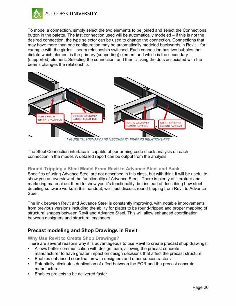
To model a connection, simply select the two elements to be joined and select the Connections button in the palette. The last connection used will be automatically modeled – if this is not the desired connection, the type selector can be used to change the connection. Connections that may have more than one configuration may be automatically modeled backwards in Revit – for example with the girder – beam relationship switched. Each connection has two bubbles that dictate which element is the primary (supporting) element and which is the secondary (supported) element. Selecting the connection, and then clicking the dots associated with the beams changes the relationship.
FIGURE 16: PRIMARY AND SECONDARY FRAMING RELATIONSHIPS
The Steel Connection interface is capable of performing code check analysis on each connection in the model. A detailed report can be output from the analysis.
Round-Tripping a Steel Model From Revit to Advance Steel and Back Specifics of using Advance Steel are not described in this class, but with think it will be useful to show you an overview of the functionality of Advance Steel. There is plenty of literature and marketing material out there to show you it’s functionality, but instead of describing how steel detailing software works in this handout, we’ll just discuss round-tripping from Revit to Advance Steel. The link between Revit and Advance Steel is constantly improving, with notable improvements from previous versions including the ability for plates to be round-tripped and proper mapping of structural shapes between Revit and Advance Steel. This will allow enhanced coordination between designers and structural engineers.
Precast modeling and Shop Drawings in Revit
Why Use Revit to Create Shop Drawings? There are several reasons why it is advantageous to use Revit to create precast shop drawings: • Allows better communication with design team, allowing the precast concrete
manufacturer to have greater impact on design decisions that affect the precast structure • Enables enhanced coordination with designers and other subcontractors • Potentially eliminates duplication of effort between the EOR and the precast concrete
manufacturer • Enables projects to be delivered faster
Page 21
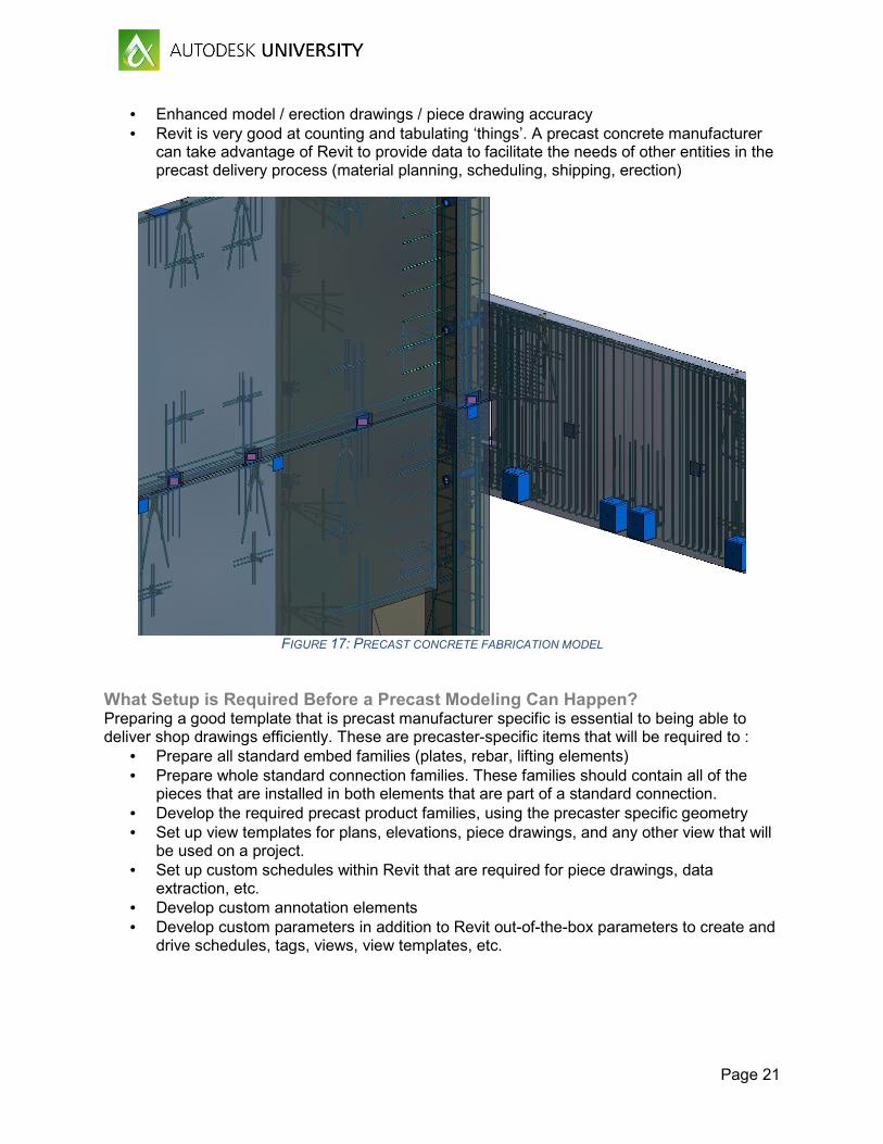
• Enhanced model / erection drawings / piece drawing accuracy • Revit is very good at counting and tabulating ‘things’. A precast concrete manufacturer
can take advantage of Revit to provide data to facilitate the needs of other entities in the precast delivery process (material planning, scheduling, shipping, erection)
FIGURE 17: PRECAST CONCRETE FABRICATION MODEL
What Setup is Required Before a Precast Modeling Can Happen? Preparing a good template that is precast manufacturer specific is essential to being able to deliver shop drawings efficiently. These are precaster-specific items that will be required to :
• Prepare all standard embed families (plates, rebar, lifting elements) • Prepare whole standard connection families. These families should contain all of the
pieces that are installed in both elements that are part of a standard connection. • Develop the required precast product families, using the precaster specific geometry • Set up view templates for plans, elevations, piece drawings, and any other view that will
be used on a project. • Set up custom schedules within Revit that are required for piece drawings, data
extraction, etc. • Develop custom annotation elements • Develop custom parameters in addition to Revit out-of-the-box parameters to create and
drive schedules, tags, views, view templates, etc.
Page 22
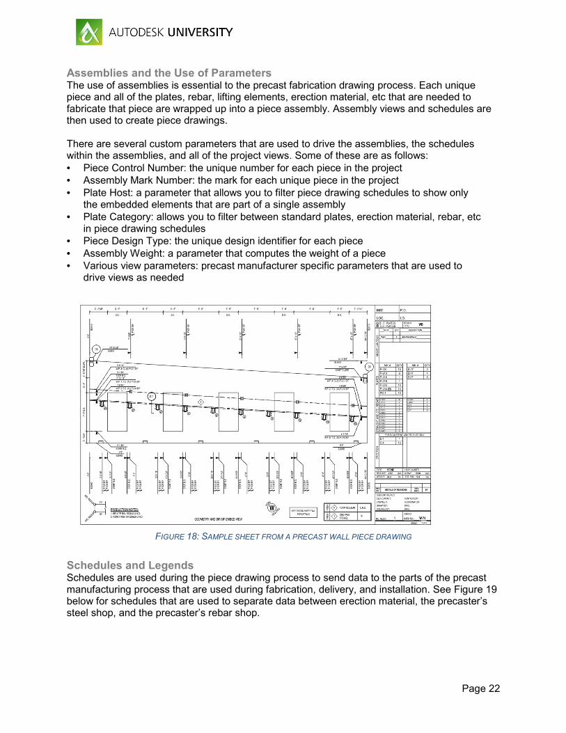
Assemblies and the Use of Parameters The use of assemblies is essential to the precast fabrication drawing process. Each unique piece and all of the plates, rebar, lifting elements, erection material, etc that are needed to fabricate that piece are wrapped up into a piece assembly. Assembly views and schedules are then used to create piece drawings. There are several custom parameters that are used to drive the assemblies, the schedules within the assemblies, and all of the project views. Some of these are as follows: • Piece Control Number: the unique number for each piece in the project • Assembly Mark Number: the mark for each unique piece in the project • Plate Host: a parameter that allows you to filter piece drawing schedules to show only
the embedded elements that are part of a single assembly • Plate Category: allows you to filter between standard plates, erection material, rebar, etc
in piece drawing schedules • Piece Design Type: the unique design identifier for each piece • Assembly Weight: a parameter that computes the weight of a piece • Various view parameters: precast manufacturer specific parameters that are used to
drive views as needed
FIGURE 18: SAMPLE SHEET FROM A PRECAST WALL PIECE DRAWING
Schedules and Legends Schedules are used during the piece drawing process to send data to the parts of the precast manufacturing process that are used during fabrication, delivery, and installation. See Figure 19 below for schedules that are used to separate data between erection material, the precaster’s steel shop, and the precaster’s rebar shop.

Page 23
Some other ideas for how schedules can be used:
• Piece marking: Since Revit does not have a great way to tell if a piece is unique (for piece marking purposes), we use schedules that show a piece length, width, and weight as a first pass at
• Product counting schedules: used to count the total number of pieces on a project, the number of plates, amount of rebar, etc
• Piece tracking: Used to track where a piece is in the piece drawing or fabrication process; each piece is marked as reinforced, annotated, checked, issued, or fabricated.
FIGURE 19: SAMPLE PIECE DRAWING SCHEDULES
Legends are used extensively for text and details that are often re-used on piece drawings:
• Rebar bend diagrams • Piece finish legends • Typical piece details (used by several pieces in the project) • Piece end indicators (end 1 – end 2) • Assembly view titles
Third Party Tools There are a few third part tools that will automate some of the repetitive tasks that are required for precast fabrication modeling:
• Edge^Revit (http://www.edgeforrevit.com/) – we use this tool to automate the assembly creation process, and the piece drawings view and schedule creation process. Edge has a tool that automatically detects all of the elements that are cast into a single piece, adds

Page 24
those elements to the piece assembly, and assigns parameter data to those elements so the data can be properly displayed in the piece drawing schedules.
• AGA CAD Tools4BIM (http://www.aga-cad.com/products/packages/precast-concrete) – this addin can be used to automate the modeling of precast connections. There are also tools to automatically create assemblies (similar to Edge^Revit) and to assist in piece marking.