Embed Size (px)
Citation preview

F-70H and F-70L Helium Compressors
Operating Manual
Sumitomo (SHI) Cryogenics of America, Inc. 1833 Vultee Street
Allentown, PA 18103-4783 U.S.A.
Revision A: September 2008 267472A


TABLE OF CONTENTS
Page
SAFETY……… ................................................................................................................. 1
SERVICE…….. ................................................................................................................. 5
INTRODUCTION ............................................................................................................ 7 Helium Compressors, Models F-70H and F-70L.................................................. 7
PRINCIPLES of OPERATION.......................................................................................... 9
DESCRIPTION ............................................................................................................. 11 Components ....................................................................................................... 11
SPECIFICATIONS ......................................................................................................... 13 F-70H Compressor (high voltage model) ............................................................ 13 F-70L Compressor (low voltage model) .............................................................. 13 Electrical Characteristics ................................................................................... 13 Front Panel Connections..................................................................................... 14 Front Panel Mounted Items................................................................................. 14 Environmental Requirements.............................................................................. 15 Mounting Position................................................................................................ 15 Cooling Requirements ....................................................................................... 15 Water Quality Requirements ............................................................................... 15 Helium Gas Pressures ...................................................................................... 16 Refrigerant Quality ............................................................................................ 16 Color Codes ........................................................................................................ 16 Optional Spacing................................................................................................. 16 Maintenance Intervals ......................................................................................... 16 Noise Level ......................................................................................................... 16 Dimensions ......................................................................................................... 17 Weight ................................................................................................................ 17 General Operating Conditions............................................................................. 17 Supplier Name and Address ............................................................................... 17 Regulatory Compliance....................................................................................... 18
INSTALLATION ............................................................................................................ 23 Introduction ......................................................................................................... 23 Receipt Inspection Instructions ........................................................................... 23 Unpackaging and Product Inspection Instructions ............................................ 24 Compressor Location ......................................................................................... 26 Transformer Voltage Tap Selection for F-70L..................................................... 26 Transformer Voltage Tap Selection for F-70H .................................................... 26 Electrical Supply Connection .............................................................................. 27 Coolant Connections........................................................................................... 28 Compressor Checkout ...................................................................................... 29 Install the Gas Lines........................................................................................... 30 Install the Cold Head Cable(s) ........................................................................... 31
Diagnostic Interface Connector........................................................................... 31 Prestart Check .................................................................................................... 33
i

TABLE OF CONTENTS
Page
OPERATION ............................................................................................................... 35 Starting .............................................................................................................. 35 Stopping ............................................................................................................ 35 Cold Head Only Run ......................................................................................... 35 Restarting After a Power Failure ....................................................................... 35 Automatic Restarting After a Helium High Temperature Shutdown Error ......... 36 System Status Display ........................................................................................ 36
TROUBLESHOOTING ................................................................................................. 37 Error Conditions .................................................................................................. 37 Clearing Error Conditions.................................................................................... 37 Restarting after an Error Condition ..................................................................... 38 Troubleshooting Guide ...................................................................................... 38 Diagnostic Interface Connector Pin Functions .................................................... 46
ILLUSTRATIONS LIST Figure 1 Compressor Flow Diagram …………………………………………………9 Figure 2 F-70H and F-70L Compressors, Front View ..................................... 19 Figure 3 F-70H and F-70L Compressors, Dimensions..................................... 20 Figure 4 Fuse Locations in the Electrical Chassis............................................ 21 Figure 5 Voltage Selection Connectors............................................................ 27 Figure 6 Voltage Tap Configurations................................................................ 27 Figure 7 Connect Mains Power Supply Cable to Mains Power Receptacle ..... 28 Figure 8 Connect and Remove the Water Lines .............................................. 29 Figure 9 Attach Identification Label .................................................................. 30 Figure 10 Connect Gas Line to Compressor or Cold Head.............................. 31 Figure 11 Set the Configuration Mode Selector Switch.................................... 32 Figure 12 F-70H Compressor Wiring Diagram................................................ 42 Figure 13 F-70H Compressor Wiring Schematic.............................................. 43 Figure 14 F-70L Compressor Wiring Diagram ................................................. 44 Figure 15 F-70L Compressor Wiring Schematic .............................................. 45 TABLES Table 1 Diagnostic Interface Connector Pin Functions, Configuration Mode 1 46 Table 2 Diagnostic Interface Connector Pin Functions, Configuration Mode 2 47
SJM P/N 267472A
i

SAFETY
GENERAL SCAI equipment is designed to operate safely when the installation, operation and servicing are performed in accordance with the instructions in this technical manual. For Service Center locations, see the Service section of this manual.
SPECIAL NOTICES
Three types of special notices -- WARNINGS, CAUTIONS and NOTES are used in this technical manual.
WARNINGS call attention to actions or conditions that can result in serious injury or death.
CAUTIONS call attention to actions or conditions that can result in damage to the equipment or in abnormal performance.
NOTE
NOTES give important, additional information, explanations or recommendations related to the appropriate topic or procedure. WARNINGS and CAUTIONS, like other safety instructions, appear within rectangles in the text where they are applicable. Because of their importance, they are summarized in this Safety section and in the General Technical Manual, and should be read first.
NOTE
Changes to this manual since the previous issue are identified by parallel lines (||) in the right margins.
1

Safety
WARNINGS
AVOID ELECTRIC SHOCK. All electrical supply equipment must meet applicable codes and be installed by qualified personnel.
Disconnect the power to the compressor before troubleshooting the electrical components.
Permit only qualified electrical technicians to open electrical enclosures, to perform electrical checks or to perform tests with the power supply connected and wiring exposed. Failure to observe this warning can result in serious injury or death. AVOID INJURY. Never use compressed helium gas from a cylinder without a proper regulator. Overpressure can cause serious injury if the system equipment ruptures.
During operation, some surfaces under the compressor’s cover become hot. Allow the compressor to cool for 1/2 hour after shutdown before removing the cover for maintenance.
Always wear eye protection when handling pressurized gas lines and other pressurized equipment. Never apply heat to a pressurized gas line or other pressurized components.
Disconnect gas lines only when the compressor is stopped. Disconnecting the cold head while it is cold can create excessively high internal pressure as the gas warms. Material failure and uncontrolled pressure release can cause serious injury.
Use two wrenches when disconnecting a gas line coupling to avoid loosening the cold head or compressor coupling. Gas pressure can project the coupling with enough force to cause serious injury.
The compressor is charged with helium gas. Except when disconnecting the adsorber or the gas lines, vent both supply and return Aeroquip couplings to atmospheric pressure before disassembly. Uncontrolled pressure release can cause serious injury.
Always vent a gas-charged component before beginning to disassemble its couplings. Gas pressure can launch a loose coupling with enough force to cause serious injury.
The adsorber is charged with helium gas. Follow the used adsorber venting procedure for safe disposal of the used adsorber.
CAUTIONS
PRESERVE YOUR WARRANTY. Modification to equipment without the consent of the manufacturer will void the warranty.
Specifications require the use of 99.999% pure helium gas. Using a lesser quality of helium can damage the system and void the warranty. AVOID GAS LEAKS. Check the condition of the gasket face seal on the male half of each Aeroquip coupling. Be sure the gasket face seal is in place and the sealing surfaces on both the male and female halves are clean before connecting. Replace the gasket face seal if it is damaged or missing.
Keep the gas line couplings aligned when making or breaking a coupling connection. Leaks can occur due to the weight of the gas line or due to a sharp bend near the connection.
2

Safety
CAUTIONS (continued)
AVOID CONTAMINATION. When checking the compressor for shipping damage, do not connect the gas lines and the cold head. The components may become contaminated with compressor oil.
Follow the charging or venting procedures to prevent reversed flow of system gas. Do not charge through the supply coupling. Do not vent through the return coupling. Reversed flow can contaminate the system with compressor oil.
A leaking coupling on an adsorber should not be repaired in the field. Consult a Service Center. Venting the adsorber will introduce contaminants to the system, which cannot be removed in the field. PREVENT EQUIPMENT DAMAGE. Damage to gas lines can result from crimping by repeated bending and repositioning.
Always thoroughly drain the coolant from the cooling circuit if the compressor is to be shipped or stored.
If the compressor is wired for 380/415 (±10%) V3~ electrical service, connecting to a higher voltage may damage the control circuit. Similarly, if it is wired for 480 V3~, 60 Hz, it can be damaged by connecting to 380/415 V3~.
Never pull a vacuum on the compressor or on the cold head. The motors will short circuit if started.
After starting the system for the first time, to be certain that the water lines are properly connected, check that the outlet water temperature is warmer than the inlet water.
For an installation using a water chiller or other circulating cooling system: Use pure ethylene glycol with water for the coolant antifreeze solution. Do not use commercial ethylene glycol sold for automotive cooling systems, which usually contains a fine grit material that can damage the cooling system. AVOID A MALFUNCTION. Repeatedly charging the system with helium gas rather than locating and repairing gas leaks can cause a malfunction. Impurities are introduced at an abnormal rate and can freeze in the cold head.
Do not allow air to get into the helium gas refrigerant of the system. Moisture from the atmosphere can seriously degrade cold head performance. AVOID EQUIPMENT FAILURE, CONTAMINATION OR A NUISANCE SHUTDOWN. Do not tip the compressor greater than 5 degrees from horizontal, to avoid flowing oil into unwanted places.
3

(This page is intentionally blank.)
4

SERVICE
SERVICE CENTERS HEADQUARTERS
Eastern U.S.A.
Sumitomo (SHI) Cryogenics of America, Inc. 1833 Vultee Street Allentown, PA 18103-4783
TEL: (800) 525-3071 or (610) 791-6750 FAX: (610) 791-3904
Sumitomo (SHI) Cryogenics of America, Inc. 1833 Vultee Street Allentown, PA 18103-4783
Sales and Parts TEL: (800) 525-3072 or (610) 791-6700 FAX: (610) 791-0440
Service TEL: (800) 525-3071 or TEL: (610) 791-6750
Western U.S.A.
Sumitomo (SHI) Cryogenics of America, Inc. 456 Oakmead Parkway Sunnyvale, CA 94085
TEL: (408) 736-4406/4407 FAX: (408) 736-7325
Europe Sumitomo (SHI) Cryogenics of Europe, Ltd. 3 Hamilton Close Houndmills Industrial Estate Basingstoke Hampshire RG21 6YT United Kingdom
TEL: +44 1256 853333 FAX: +44 1256 471507
Sumitomo (SHI) Cryogenics of Europe, GmbH Daimlerweg 5a D-64293 Darmstadt Germany
TEL: +49 6151 860 610 FAX: +49 6151 800 252
Asia Sumitomo Heavy Industries, Ltd. Service Section Cryogenics Division 2-1-1 Yato-Cho Nishitokyo-City Tokyo 188-8585 Japan
TEL: +81 424 68 4265 FAX: +81 424 68 4462
SHI Cryogenics Group Shanghai Technical Support Center Sumitomo Heavy Industries (Shanghai) Ltd. Department M, 3
rd Floor
205 Taigu Road, Waigaoqiao Free Trade Zone, Pudong Shanghai 200131 People’s Republic of China
TEL: +86 21 5868 2721 FAX: +86 21 5868 2725
5

(This page is intentionally blank.)
6
INTRODUCTION
Helium Compressors, Models F-70H and F-70L
The compressors are designed to deliver high-pressure, oil-free, helium gas to cryogenic refrigerators. Cold head cables are used with the compressor to supply electrical power to cold heads. Self-sealing gas couplings allow for easy connection to and disconnection from the rest of the closed-cycle cryogenic refrigeration system.
The information in this manual pertains only to the F-70H (high voltage model) and the F-70L (low voltage model) Compressors. Other components used to form an operating system are described in separate technical manuals.
Pressures are stated as gauge, not absolute. Pressure units are bar and pounds per square inch (psig). For reference: 1 bar = 14.5 psig. 1 MPa = 10 bar Definition of Symbols used in this manual and on equipment
7

(This page is intentionally blank.)
8

PRINCIPLES of OPERATION
Figure 1 Compressor Flow Diagram
Key
TSG Gas temperature thermistor
TSWi Water-in temperature thermistor
TSWo Water-out temperature thermistor
ARV Atmospheric relief valve
IRV Internal relief valve
SV Solenoid valve
PT Pressure transducer
PG Pressure gauge
The compressor continuously draws low-pressure helium from the system return line. It compresses, cools and cleans the gas, then delivers it through the system gas supply line to the cold head. See Figure 1.
9

Principles of Operation
When helium gas leaves the compressor capsule, the gas contains heat and compressor lubricant. Both must be removed. From the compressor capsule, the hot gas with its entrained oil flows out of the shell and through the bulk oil separator. The gas next flows through one circuit of a three-circuit, water cooled, heat exchanger, where it is cooled. Next, the gas passes through the final oil separator and the adsorber for oil and moisture removal. From the adsorber, the high-pressure helium gas flows to the cold head through the gas lines.
Through the system gas return line, low-pressure gas from the cold head flows into the compressor.
A gas line containing an internal relief valve (IRV) connects the high-pressure line to the low-pressure line. The relief valve will open to prevent overloading the motor when the system gas lines are not connected to the compressor.
Oil is separated from the gas in three stages. The first stage is by gravity when the gas passes through the bulk oil separator. The second stage is in the final oil separator whose element collects oil mist from the gas; oil is agglomerated and returned to the compressor. The third stage is the adsorber that removes any remaining oil the gas is carrying.
Oil collected in the oil separators flows back to the compressor capsule through capillary tubes and orifices. The differential gas pressure across the system is the moving force, and the restriction size limits the amount of gas bypassed. The small amount of oil collected in the adsorber remains there and is removed only by replacing the adsorber.
Before being returned to the compressor capsule, the oil separated in the bulk oil separator flows through the heat exchanger where it is cooled. It is then injected into the low pressure side of the compressor capsule to adsorb heat and lubricate the compressor capsule.
10

Description
Components
Adsorber - The adsorber removes any oil and moisture the gas is carrying which did not drop out in the separator. The adsorber has a finite life and must be replaced at regular intervals.
Atmosphere Relief Valve [ARV] – The pressure relief valve prevents the compressor from operating at an unsafe pressure by venting to the atmosphere.
Bulk Oil Separator - Removes much of the entrained oil from the gas stream. This unit needs no servicing or replacement
Cold Head Power Receptacle - Mounted on the front panel for connecting a cable to supply electrical power from the compressor to the cold head.
Compressor Capsule - Helium, scroll compressor with a hermetically sealed motor.
Compressor High Temperature Motor Protector Switch - Located inside the compressor motor, the switch senses compressor motor temperature and stops the motor if the temperature is too high. The switch resets after cool down.
Electrical Chassis - The electrical box contains electrical components and connections and distributes power to all system circuits.
Final Oil Separator - Removes most of the remaining entrained oil from the gas stream. This unit needs no servicing or replacement.
Fuses – Three (3) time delay, class CC fuses, located inside the electrical chassis box, protect the transformer. Three (3) time delay, 5x20 mm fuses, located on the printed circuit board inside the electrical chassis box, protect the cold head supply circuit.
Heat Exchanger - Uses water to cool the high-pressure helium refrigerant and the compressor’s lubricating oil.
Helium Charge - A size 4, male (4M), Aeroquip coupling located on the front of the compressor is used for charging or venting helium gas refrigerant.
Helium Supply and Helium Return Pressure Couplings – Both supply (high pressure) and return (low pressure) are self-sealing, size 8, male (8M), Aeroquip, bulkhead couplings and are the points of connection on the front panel for the gas lines.
Internal Relief Valve [IRV] - The internal relief valve opens to allow the compressor to be operated in the stand-alone mode or when the system gas lines are disconnected, to avoid overloading the motor.
Mains Power Switch - Mounted on the front panel, it provides a means to disconnect power and it protects the compressor from electrical overload. This device is labeled Main Power.
Oil Capillary - The capillary returns oil collected in the oil separator sump to the compressor for recycling.
Oil Filter - Filters in the oil lines protect the oil return capillary and the orifices.
Oil Injection Orifices - These orifices are installed in the oil return lines and control the flow rate of oil returned to the compressor.
11

Description
Pressure Gauge - Indicates gas pressure in the supply line. When the compressor is not running, the gauge located on the compressor’s front panel shows the equalization pressure.
Supply Gas High Temperature Thermistor - Senses discharge gas temperature. It causes the compressor to shut down if the temperature of the high-pressure helium from the compressor is too high.
Water High Temperature Thermistors - Sense water temperature. One each is located in the “water in” line and in the “water out” line. They provide a warning if the inlet or the outlet water temperature is too high. High outlet water temperature indicates low water flow.
Water In and Out Fittings – F-70H is fitted with two (2) ½" MNPT and F-70L is fitted with two (2) ½” Serto elbows mounted on the front panel.
12

SPECIFICATIONS
F-70H Compressor (high voltage model) Details: Two (2) size 8M gas couplings; water-cooled; 480 (±10%) V3~, 60 Hz or 380/415 (±10%) V3~, 50 Hz. F-70L Compressor (low voltage model) Details: Two (2) size 8M gas couplings; water-cooled; 200 (±10%) V3~, 50/60 Hz. Electrical Characteristics
Service required: Delta connected, 4 wires (3 phase plus protective ground or earth.)
A screw-mounted, detachable connector is provided on the electrical front panel for connecting power to the compressor.
F-70H (high voltage model) Transformer Voltage Tap Selection: The proper transformer voltage tap must be selected to match the incoming supply voltage by proper position of the transformer supply connector located behind the voltage selection access panel on the electrical front panel. See the section Electrical Supply Connection.
Power consumption: Gifford-McMahon (GM) Operation Startup
6.6 – 6.9 kW @ 50 Hz <8.5 kW @ 50 Hz 7.5 – 7.8 kW @ 60 Hz <9.0 kW @ 60 Hz
Pulse Tube (PT) Operation Startup
6.7 – 7.2 kW @ 50 Hz <8.5 kW @ 50 Hz 8.0 – 8.5 kW @ 60 Hz <9.0 kW @ 60 Hz
Rated load current: For the F-70H compressor, 13 amperes
For the F-70L compressor, 24 amperes (GM only)
Locked rotor current: For the F-70H compressor, 75 amperes at 60Hz, 67 – 74 amperes at 50Hz
For the F-70L compressor, 164 amperes at 60Hz, 163 – 179 amperes at 50Hz
Internal circuit protection Transformer: (3) 1.0 ampere, time delay, class CC fuses (F-70H) (FU-1, 2 and 3) (3) 2.0 amperes, time delay, class CC fuses (F-70L) (FU-1, 2 and 3) Cold head motor: (3) 0.63 ampere, time delay, 5x20 mm fuses (FU-4, 5 and 6) Control circuit: (2) 0.75 ampere, resettable, poly fuses (not replaceable).
Fuses are located inside the electrical chassis box, for service by qualified electrical technician only. See Figure 4.
Cold head power requirement: 200 V3~, 0.4 amperes, supplied from the compressor.
Cold head power supply: A cable connects the cold head to the compressor.
Class I: Grounded equipment
Ingress protection: IP4X
Compressor control logic provides: � ON and OFF buttons for local operation of the compressor and the cold head. � Front panel LCD display (16 characters) of elapsed time and system status. � (2) Push buttons, up and down arrows, to scroll the LCD display
13

Specifications � Interlock to prevent starting the compressor and the cold head if the main power phase sequence is incorrect. � Automatic restart after power interruption. � Automatic shutoff for the following system faults. Operator correction is required before restart. � High gas discharge temperature, when thermistor reads > 93° C (200° F).
(5 automatic restarts at 20 minute intervals before operator correction required.) � High compressor motor windings temperature, switch opens at 160° C (320° F), resets at 69° C (156° F). � High compressor motor current draw: F-70H trips at 14 amperes.
F-70L trips at 32 amperes. � Open cold head (valve motor) fuse(s) � Low gas return pressure, < 1.03 bar (15 psig) � Incorrect DB-25 configuration compared to continuity value of DB-25 pins 7 and 8 �
Error warning displayed for the following system faults: � High water temperature, > 35° C (95° F); � Low water flow, water out, > 46° C (115° F).
See the Compressor Wiring Diagrams, Figures 12, 13, 14 and 15. Front Panel Connections (See Figure 2.) � Helium gas connections: size 8, male (8M) Aeroquip couplings, high-pressure supply
(red) and low-pressure return (green). � Helium fill port: size 4, male (4M) Aeroquip coupling. � Cooling water connections: F-70H, Swagelok bulkhead fittings, ½” MNPT. F-70L, 90º swivel elbows, ½” Serto �
Cold head cable receptacle: Amphenol MS3102A-14S-2S � Mains power connector: Screw-mounted rectangular industrial connector � Diagnostic interface connector: DB-25, for control and to indicate error condition �
Proper DB-25 configuration mode must be selected at installation. See Diagnostic Interface Connector in the Installation section of this manual � Serial connector: DB-9, not for customer’s use.
Front Panel Mounted Items (See Figure 2.) �
Supply pressure gauge (0-40 bar, 0-600 psig, 0-4000 kPa) � LCD display (Elapsed time meter display is the default position) � ON and OFF buttons � (2) Display buttons (to scroll the LCD display) � Main power switch � Voltage selection access panel � Configuration mode selector switch
14

Specifications
Environmental Requirements
Operating Storage
Ambient Temperature 4° C to 40° C (40° F to 104° F)
-20° C to 65° C (-4° F to 150° F)
Relative Humidity 30% to 70% 10% to 90% (non-condensing)
Magnetic Field Limits �
50 Gauss
Atmospheric Pressure 70 kPa to 110 kPa 20 kPa to 110 kPa
NOTE
Operating the equipment out of specifications may void the warranty. Mounting Position
Compressor must be mounted base down and level within 5 degrees of horizontal. Cooling Requirements
Application Cooling Water Flow Rate
4K GM and 10K GM Cold Head 6 to 9 L/min (1.6 to 2.4 gpm)
4K PT Cold Head 6.8 to 9 L/min (1.8 to 2.4 gpm)
Cooling water inlet temperature: 5° C to 25° C (41° F to 77° F)
Cooling water outlet temperature: 45° C (113° F) maximum
Cooling water supply pressure: 8 bar (116 psig) maximum
Pressure drop at 9 L/min: <1 bar (<14.5 psig)
Alternative coolant 50% pure ethylene glycol + 50% water
Ethylene glycol/water (50/50) flow rate 7.8 to 11.7 L/min (2.1 to 3.1 gpm)
Water Quality Requirements
Water supplied for cooling the compressor should be filtered through a 300-micron screen and meet the following quality limits:
Item
Initial Values for non-Replenished (closed) System
Values for Continuously Replenished (open) System
Suspended solids, µg/L <250 <250
Particle size, µm <300 <300
pH (25° C) 6.5 to 8.0 6.0 to 8.0
Alkalinity (ppm) 100 max. 50 max.
Hardness (ppm) 200 max. 50 max.
Chloride (ppm) 200 max. 50 max.
Sulfate (ppm) 200 max. 50 max.
Iron (ppm) 1.0 max. 0.30 max.
Sulfur ion (ppm) None detected None detected
Ammonium ion (ppm) 1.0 max. 0.20 max.
Silica (ppm) 50 max. 30 max.
15

Specifications
Helium Gas Pressures
Application Equalization Pressure at 20° C (68° F) for 12 to 20 m
long gas lines
Operating (Supply) Pressure *
4KGM Cold Head, 50/60 Hz 13.5 - 14.0 bar {13.6 bar (198 psig) nominal}
18.0 - 23.0 bar (261-334 psig)
10KGM Cold Head, 60 Hz 13.5- 14.0 bar {13.6 bar (198 psig) nominal }
18.0 - 23.0 bar (261-334 psig)
10KGM Cold Head, 50 Hz 14.0 - 14.5 bar {14.3 bar (207 psig) nominal}
18.3 - 23.2 bar (265-337 psig)
4K Pulse Tube Cold Head, 50/60 Hz
16.5 - 17.0 bar {16.6 bar (240 psig) nominal}
20.0 - 25.0 bar (290-363 psig)
*The operating pressure varies according to the heat load of cold head and ambient temperature. Refrigerant Quality
Refrigerant is 99.999% pure helium gas with a dew point temperature less than -50° C (-58° F) at 20.7 bar (300 psig).
PRESERVE YOUR WARRANTY. Specifications require the use of 99.999% pure helium gas. Using a lesser quality of helium can damage the system and void the warranty.
Color Codes
The compressor helium connections are color-coded to match color labels provided with the gas lines.
SUPPLY (red) - Helium high-pressure gas supply from the compressor to the cold head. RETURN (green) - Helium low-pressure gas return to the compressor from the cold head.
Optional Spacing
Allow 600 mm (24") space in front of the compressor for access to electrical, water and gas connections. Allow 600 mm (24") space on the left side (when facing the front) of the compressor for maintenance of the adsorber. Maintenance Intervals
Compressor adsorber: 30,000 operating hours Noise Level
< 70 dB(A) at 1m
16

Specifications
Dimensions
See Figure 3. Three removable eyebolts are furnished for lifting.
Weight (approximate)
Compressor: 100 kg (220 pounds) General Operating Conditions
Normal pressure and temperature data are listed above. User should record monthly the operating conditions in a logbook. Keep this record of data for reference and later comparisons. Supplier Name and Address
Sumitomo (SHI) Cryogenics of America, Inc. 1833 Vultee Street Allentown, PA 18103-4783 U.S.A.
(610) 791-6700
17

Specifications
Regulatory Compliance
Declaration of Conformity
Manufacturer’s Name Sumitomo (SHI) Cryogenics of America, Inc.
Manufacturer’s Address 1833 Vultee Street Allentown, PA 18103 U.S.A.
Authorized Representative’s Name Sumitomo (SHI) Cryogenics of Europe, Ltd.
Authorized Representative’s Address 3 Hamilton Close Houndmills Industrial Estate Basingstoke Hampshire RG21 6YT United Kingdom
Type of Equipment Cryogenic Refrigeration Systems
Application of Council Directives 89/336/EEC, 73/23/EEC, 98/37/EC
F-70H Helium Compressor F-70L Helium Compressor
UL 471: 9th
Ed., cUR Mark CSA 22.2 No. 120 M91 – 1/1/91 – R2004 IEC 60204-1 Edition 4.1, 2000-05 IEC 60601-1:2005 EN 60601-1-2-2001 EN 61000-6-4:2001, part 2 EN 55011 EN 61000-6-2:2001 EN 61000-4-2 EN 61000-4-3 EN 61000-4-4 EN 61000-4-5 EN 61000-4-6 EN 61000-4-11
I, the undersigned, hereby declare that the equipment specified above conforms to the above Directives.
18

Specifications
Figure 2 F-70H and F-70L Compressors, Front View
19

Specifications
Figure 3 F-70H and F-70L Compressors, Dimensions
Dimensions are in inches and [mm].
20

Specifications
Fuses FU-4, 5 and 6
Fuses FU-1, 2 and 3
Figure 4 Fuse Locations in the Electrical Chassis
21

(This page is intentionally blank.)
22

INSTALLATION
Introduction
Install the F-70H or the F-70L Compressor, Cold Head Cable and the Gas Lines according to the following procedures.
The following installation procedures are based on standard arrangements of equipment, using SCAI standard components.
To prevent contaminating the components or the system, it is important to follow the procedures in this manual step by step.
NOTE
Be sure to have 99.999% pure helium gas available for installation of the system.See Refrigerant Quality in Specifications.
Receipt Inspection Instructions
AVOID EQUIPMENT FAILURE, CONTAMINATION OR A NUISANCE SHUTDOWN. Do not tip the compressor more than 5 degrees from horizontal to avoid flowing oil into unwanted places.
AVOID CONTAMINATION. When checking the compressor for shipping damage, do not connect gas lines and cold head. The components may become contaminated with compressor oil.
1. Upon receipt, inspect the shipping container and the compressor for damage.
1.1. If there is any evidence of external damage to the container, be sure the carrier’s driver sees the damage. Note it on the shipping documents and have the driver acknowledge it by his initials on the delivery receipt.
1.2. Remove the compressor from its shipping container and inspect for damage. If there was external damage to the compressor, remove its covers and check for internal damage. Notify the carrier immediately and take photographs of the damage to document your claim to the carrier. Keep the damaged shipping container.
NOTE Retain the shipping containers, if reusable, for returning the components to the factory if reconditioning is required. If internal damage is suspected, retain the shipping container for proof to the carrier.
2. Inspect for Proper Charge Pressure
2.1 The Charge Pressure of the Compressor Unit can be checked from the outside of the shipping container without removing the packaging.
23

Installation
2.2 Look through the “peep hole” on the container. View the pressure gauge on the
Compressor Unit front panel. The pressure gauge should indicate 207 – 212 PSIG at 68°F (1430 – 1460 kPa at 20°C).
2.3 If the gauge indicates 0 PSIG (0 MPa), the Compressor Unit can not be used. Contact the nearest SHIG Service Center.
3. Upon receipt, inspect Tip-N-Tell Sensor on Package for Activation
3.1 The Tip-N-Tell sensor mounted on the shipping container package surface should be checked upon receipt and before unpackaging to verify the “Compressor Unit shipping container” was NOT tipped or mishandled during transport.
3.2 If activated, Tip-N-Tell sensor turns blue in the arrow as shown below. Proceed with internal inspection.
Non-Activated (Good) Activated (Not Good) Unpackaging and Product Inspection Instructions
1. Unpackaging Instructions
1.1 Remove the straps around the package.
1.2 Remove the Packaging Cover Shell and Top Inside Cushions.
1.3 Insert and tighten the three (3) furnished eyebolts into the top of the compressor. See Figure 3.
1.4 Carefully lift the compressor off the wooden base.
1.5 Retain the reusable shipping container parts for possible reuse. This includes the wooden base with Ethafoam cushion blocks, the packaging cover shell and the top inside cushions.
2. Inspect the Tip-N-Tell Sensor on Compressor Unit for Activation.
2.1 Check the Tip-N-Tell sensor mounted on the compressor rear panel. If the Tip-N-Tell sensor shows no mishandling and there is no apparent physical damage, skip Steps 2.2 and 2.3 and proceed to the section Compressor Location.
If the Tip-N-Tell sensor indicates mishandling (arrow point is blue), proceed to either Step 2.2 or 2.3:
24

Installation
2.2 The equalization pressure is within specifications:
If the compressor has been momentarily tipped (less than one hour) and the equalization pressure is within specifications, allow it to stand upright for two hours before performing this step
AVOID ELECTRIC SHOCK. All electrical supply equipment must meet applicable codes and be installed by qualified personnel.
AVOID ELECTRIC SHOCK. Permit only qualified electrical technicians to open electrical enclosures, to perform electrical checks or to perform tests with the power supply connected and wiring exposed. Failure to observe this warning can result in serious injury or death
PREVENT EQUIPMENT DAMAGE. If the F-70H compressor is wired for 400 V3~, 50Hz (400 ±10% V3~) electrical service, connecting to a higher voltage may damage the control circuit. Similarly, if it is wired for 480 V3~, 60 Hz, it can be damaged by connecting to 400 V3~.
Connect power and water to the compressor. See the next sections Compressor Location, Electrical Supply Connection, Coolant Connections and Compressor Checkout. Test run the compressor for two (2) hours minimum. If there are no problems during this time, stop the compressor and proceed to assemble the system.
If the compressor shuts down during the two- (2) hour test, contact the nearest SCAI
Service Center.
2.3 If the equalization pressure is outside the specified range or there is physical
damage to the compressor enclosure or the compressor has been on its side or
upside down for an extended period of time (more than one hour), contact the
nearest SCAI Service Center and notify the delivering carrier of the damage.
NOTE
When checking the compressor for shipping damage, do not connect gas lines and
cold head. The components may become contaminated with compressor oil.
3. Inspect for Visible Damage of Compressor Unit.
3.1 Inspect the exterior panels of the Compressor Unit for evidence of damage.
3.2 If there was external damage to the compressor, remove the compressor unit panels
and check for internal damage. Notify the carrier immediately and take photographs of
the damage to document your claim to the carrier.
25

Installation
3.3 If any irrecoverable damage is found (e.g. oil Leakage, panel deformation), contact
the nearest SCAI Service Center.
Compressor Location
Place the compressor in a location that is protected from the elements and where the ambient temperature will always be within the range of 4° C to 40° C (40° F to 104° F).
The compressor must be installed base down, within 5 degrees of horizontal, and preferably at a height convenient for making connections and reading the pressure gauge.
Allow 600-mm (24”) space in front of the compressor for access to electrical, water and gas connections. Allow 600-mm (24”) on the left side (when facing the front) of the compressor for maintenance of the adsorber. Transformer Voltage Tap Selection for F-70L
The F-70L Compressor (low voltage model) is permanently configured for 200 (±10%) V3~, 50 Hz. No changes are required for this model. Transformer Voltage Tap Selection for F-70H
There are four (4) possible voltage taps: 380V, 400V, 415V and 480V. The compressor is factory set for 400V3~.
Before power is supplied, the following procedure must be applied only if the wires need to be changed to another supply voltage.
PREVENT EQUIPMENT DAMAGE. If the F-70H Compressor is wired for 400 V3~, 50 Hz (380/415 ±10% V3~) electrical service, connecting it to a higher voltage may damage the control circuit. Similarly, if it is wired for 480 V3~, 60 Hz, it can be damaged by connecting to 400 V3~.
AVOID ELECTRIC SHOCK. Permit only qualified electrical technicians to open electrical enclosures, to perform electrical checks or to perform tests with the power supply connected and wiring exposed. Failure to observe this warning can result in serious injury or death.
Tool required: #2 Phillips screwdriver
1. Disconnect the mains power supply to the compressor (if connected).
2. At the voltage selection access panel on the front of the compressor, remove the clear plastic cover to expose the voltage selection connectors. See Figure 5.
3. Move the exposed connector half from the incorrect voltage tap connector to the voltage tap connector labeled for the correct supply voltage. Make sure the connector latches in place. See Figure 6.
4. Replace the clear plastic window.
26

Installation
5. Reconnect the compressor’s main power.
Figure 5 Voltage Selection Connectors
380V Connection 400V Connection
415V Connection 480V Connection
Figure 6 Voltage Tap Configurations
Electrical Supply Connection
Tool required: #3 Phillips screwdriver
The F-70 compressor must be installed in a circuit capable of supplying the specified voltage and power. The wiring method used for connection to the front panel power connector must meet applicable codes.
27

Installation
AVOID ELECTRIC SHOCK. All electrical supply equipment must meet applicable codes and be installed by qualified personnel. Permit only qualified electrical technicians to open electrical enclosures, to perform electrical checks or to perform tests with the power supply connected and wiring exposed. Failure to observe this warning can result in serious injury or death.
Connect mains power supply cable into the mains power receptacle on the front panel and fasten cover with attached screws. See Figure 7.
Figure 7 Connect Mains Power Supply Cable to Mains Power Receptacle Coolant Connections
Tools required: Open-end wrench, 15/16” Open-end wrench to suit customer’s water lines fittings
Using two wrenches, connect coolant supply and return lines to the water in and water out fittings on the front of the compressor. See Figure 8. Ensure that the Water In connection is connected to the supply line from the user’s cooling water or coolant supply. Turn on the coolant and check the water lines for leaks. Tighten the fittings if necessary. See Specifications for cooling requirements.
28

Installation
Hold hex with one wrench.
Turn water line coupling with the other wrench.
Figure 8 Connect and Remove the Water Lines
PREVENT EQUIPMENT DAMAGE. Always thoroughly drain the coolant from the cooling circuit if the compressor is to be shipped or stored.
Compressor Checkout The compressor should be operated before being connected to the other system components.
1. For the F-70H (high voltage model) Compressor only, be sure that the transformer voltage taps are correctly selected to match the supply voltage.
2. Supply power to the compressor. Set the compressor’s Main Power switch to on. Push the ON button. Run the compressor for ten (10) minutes and then stop.
3. While the compressor is running, lightly touch the water supply and return lines. The return (water out) line should be warmer. If the return water line is cooler than the supply (water in) line, stop the compressor and reverse the water connections.
NOTE
The compressor has reversed-phase protection to prevent it from running in reverse. If it does not start and the LCD displays “Phase Seq – ERR”, disconnect the power and interchange any two mains supply wires (except ground). Refer to the Troubleshooting section in this manual.
NOTE
If the compressor starts but does not build pressure, turn it off immediately. It could be running in reverse despite the above-mentioned phase monitor relay. Contact a Service Center if this occurs.
This completes the checkout of the compressor.
29

Installation
Install the Gas Lines
Tool required: Open-end wrenches, 1", 1 1/8", 1 3/16"
Gas lines are shipped with protective dust plugs. Do not remove the plugs until the gas lines are ready to be attached. All bending and routing of gas lines should take place with plugs in place.
AVOID INJURY. Always wear eye protection when handling pressurized gas lines and other pressurized equipment. Never apply heat to a pressurized gas line or other pressurized components.
PREVENT EQUIPMENT DAMAGE. Damage to gas lines can result from crimping by repeated bending and repositioning.
NOTE Be sure to have 99.999% pure helium gas available at the installation site in case gas needs to be added to the system. See Refrigerant Quality in Specifications in this manual.
1. Identification labels are furnished with the gas lines. Before installing the gas lines, identify each with an appropriate label, SUPPLY (high pressure, color-coded red) or RETURN (low pressure, color-coded green) by applying the label adjacent to each Aeroquip coupling. See Figure 9.
NOTE Supply and return gas lines are identical. Labels are used to prevent making a wrong connection at installation or at reassembly following maintenance.
Figure 9 Attach Identification Label
2. Arrange the system components so that the gas lines will be protected from stress and traffic. Observe the minimum bend radius of 180 mm (7") when routing gas lines. Provide supports where needed.
3. Remove the dust caps from the compressor’s supply and return gas couplings.
4. Connect the gas lines to the compressor’s high-pressure (supply) and low-pressure (return) couplings. Use two wrenches to tighten the coupling. Torque all couplings to 47 ± 7 Nm (35 ± 5 ft. lbs.) See Figure 10. Tighten each coupling before proceeding to the next one.
30

Installation
AVOID GAS LEAKS. Check the condition of the gasket seal on the male half of each Aeroquip coupling. Be sure the gasket seal is in place and the sealing surfaces on both the male and female halves are clean before connecting. Replace the gasket seal if it is damaged or missing.
Keep the gas line couplings aligned when making or breaking a coupling connection. Leaks can occur due to the weight of the gas line or due to a sharp bend near the connection.
NOTE Retain the dust caps and plugs to re-cover the couplings when they are not in use. They protect the couplings from damage and prevent the entry of contaminants.
Figure 10 Connect Gas Line to Compressor or Cold Head
5. Using two wrenches, connect the RETURN gas line to the RETURN coupling on the cold
head. Tighten the coupling to 47 ± 7 Nm (35 ± 5 ft. lbs.).
6. Using two wrenches, connect the SUPPLY gas line to the SUPPLY coupling on the cold head. Tighten the coupling to 47 ± 7 Nm (35 ± 5 ft. lbs.).
The system equalization pressure, shown by the compressor gauge after all components have been connected, will determine if charging or venting is required. System equalization pressure should equal the value provided in the system level manual or the Specification section of this manual. Install the Cold Head Cable(s)
1. Be sure the compressor is not running by pressing the OFF button.
2. Connect the cold head cable to the cold head cable receptacle on the compressor front panel. Connect the other end of the cable to the electrical receptacle on the cold head.
Diagnostic Interface Connector
Tool required: Small, flat blade screwdriver
A female DB-25 connector is located on the front panel for remote control and to supply remote indication of the operating status of the compressor.
This connection may be configured for two different set points.
31

Installation
Application Configuration Mode Set Point
10KGM Mode 1
4KGM Mode 2
4KPT Mode 2
NOTE
If this F-70 Compressor is replacing an HC-10 Compressor, choose Configuration Mode 1. If this F-70 Compressor is replacing a CSW71Compressor, choose Configuration Mode 2.
When the compressor leaves the factory, the switch will be set for Configuration Mode 1.
The electrical characteristics and the DB-25 pin assignments for the two possible configurations are shown in Tables 1 and 2 in the Troubleshooting section of this manual.
The Configuration Selector Switch must be set for either Configuration Mode 1 or Configuration Mode 2 when the Main Power Switch is in the OFF position.
Switch position changes after power is supplied to the controller will change DB-25 electrical characteristics but will not be recorded by the controller. Loss of control and incorrect indications will result.
The selector switch handle is accessible on the front panel of the electrical chassis. See Figure 2. Move the switch handle up or down with a flat blade screwdriver. Handle up sets the switch for Configuration Mode 1. Switch handle down sets the switch for Configuration Mode 2. See Figure 11.
Figure 11 Set the Configuration Mode Selector Switch
32

Installation
Prestart Check
1. Check that the cooling water lines are connected and that the supply is connected to the water in connection. Turn on the coolant and check the lines for leaks. Tighten the fittings if necessary. See Cooling Requirements in Specifications.
2. Check that all electric connections are made:
a. Power to the compressor b. Cold head cable c. Diagnostic interface cable
3. Check that the diagnostic interface selector switch is properly set (if used).
4. Check that the electrical power supply is switched on.
5. Check that the equalization pressure is as specified when the compressor is at room temperature, 20° C (68° F). A change in temperature, higher or lower, will cause a small change, higher or lower, in the equalization pressure. If the pressure is far from the specified equalization pressure, the gas charge is incorrect and may indicate a leak or incorrect filling.
33

(This page is intentionally blank.)
34

OPERATION
NOTE The START/STOP buttons will only work in Configuration Mode 1. ON/OFF operation in Configuration Mode 2 is controlled remotely.
Starting
DB25 Configuration Mode 1
Supply power to the compressor. Turn the knob of the main power switch on the front of the compressor to ON. Push the ON button on the compressor’s front panel. The compressor and the cold head will start.
DB25 Configuration Mode 2
The compressor only responds to the DB25 diagnostic interface RUN/STOP signals in this mode.
PREVENT EQUIPMENT DAMAGE. After starting the system for the first time, to be certain that the water lines are properly connected, check that the outlet water temperature is warmer than the inlet water.
Stopping
DB25 Configuration Mode 1
Push the OFF button. The compressor and the cold head will stop.
DB25 Configuration Mode 2
The compressor only responds to the DB25 diagnostic interface RUN/STOP signals in this mode.
Cold Head Only Run
For running the cold head only to perform a maintenance procedure, the cold head receptacle can be energized without running the compressor by:
1. While the system is off, scrolling the display until “Cold Head Run” is shown
2. While “Cold Head Run” is displayed, press the ON button.
The cold head will run until the OFF button is pressed or until 30 minutes of running has occurred. Restarting after a Power Failure
When the power comes on, the microprocessor will determine if the last shutdown was due to a power outage. If the operator turns off the system by the main power switch, it will be detected as a power outage.
If the compressor power was interrupted by a power outage, the compressor and the cold head will restart automatically when power is restored, after a slight delay.
If the compressor stops for other reasons, compressor troubleshooting is required.
35

Operation
Automatic Restarting After a Helium High Temperature Shutdown Error
If a helium discharge high temperature shutdown error causes a shutdown of the system, the compressor will attempt to restart itself 5 times at 20 minute intervals before a reset signal must be provided to the compressor. A reset signal or power outage will clear the shutdown error and reset the automatic restart counter.
If the system is set for DB25 Configuration Mode 2 and a helium high temperature shutdown error occurs, the system will ignore automatic resets during the first 19 minutes of the 20 minute interval to prevent rapid on-off cycling of the compressor. System Status Display
Normal conditions: When all systems are operating normally, with no system errors, the following lines are displayed on the LCD in the order listed below by scrolling the display. Press the DISPLAY buttons (up and down arrows) to scroll the LCD. Scrolling past the bottom of the display will start back at the top and repeat. If the DISPLAY button is pressed and not pressed again after 30 seconds, the display will return to the first line (ET).
Elapsed time in hours to one decimal place and control state Helium Temp-OK Water Temp-OK Water Flow-OK Motor Temp-OK Phase Seq (sequence)-OK Return Press-OK Oil Level-OK DB-25 Config (switch configuration)-OK Rtn Press (current return pressure) Software Version Cold Head Run (When in OFF state only)
Error conditions: If a system error occurs that causes an alarm or shutdown condition, the monitor point as listed above will change from “OK” to “ERR” and that monitor point will be scrolled to the top for display.
Any point that has not failed will continue to display OK if the operator manually scrolls the display.
If additional points fail before the operator resets the first error(s), the latest point to fail will change from “OK” to “ERR” and will be scrolled to the top for display. In this way, the operator will see the most recent fault displayed on the LCD and, by manually scrolling the display, can see other error conditions that lead up to the latest.
If a monitoring sensor is disconnected, the display for that monitor point will change from “OK” to “FAIL”.
36

TROUBLESHOOTING
Error Conditions
An error condition will cause either a system alarm or a shutdown. The following table lists the alarm and the shutdown errors that are monitored. Overload trip of the Mains Power switch (described below) is not monitored or reported.
LCD Display First Line
Type Error Indication
Helium Temp-ERR
Shutdown High helium discharge temperature
Temperature > 93°C (200°F)
Water Temp-ERR
Alarm High water supply temperature.
Temperature > 35°C (95°F).
Water Flow-ERR Alarm Low water flow Temperature > 46°C (115°F)
Motor Temp-ERR
Shutdown High compressor motor winding temp (internal protector open)
Return Pressure > 140 psig while compressor is commanded on.
Phase Seq-ERR Shutdown Phase sequence or open fuse
Monitored by microprocessor
Return Pressure-ERR
Shutdown Loss of gas charge Return pressure < 15 psig.
Oil Level-ERR Not Used
DB-25 Config1-ERR (or Config2)
Shutdown Remote cable does not match switch setting
Monitored by microprocessor
If the compressor has been shut down by one of these interlocks, do not restart until the problem has been found and corrected. Refer to the Troubleshooting Guide to identify the problem.
In the event of a shutdown error, the compressor motor and cold head valve motor are turned off. The microprocessor will annunciate the error condition via signals at the System Diagnostics Connector and via the LCD Display. Signals are available on the 25-pin connector for output to an external device. See Figure 2 and Tables 1 and 2.
The Mains Power switch trips when steady-state current exceeds 1.2 x the front panel set point. When tripped, the switch knob locates halfway between the on and off positions. Clearing Error Conditions
NOTE Errors can be cleared locally only when configuration mode is set for Mode 1. When configuration mode is set for Mode 2, errors must be cleared using the DB25 diagnostic interface.
When an error is corrected, the message(s) can be cleared from the display and the system diagnostics connector by any of the following procedures: �
Apply a momentary signal to the diagnostic interface connector, or � Press the DISPLAY UP and DISPLAY DOWN (arrow) buttons simultaneously, or � Turn the Main Power switch to off, pause briefly, then turn back on
37
Troubleshooting
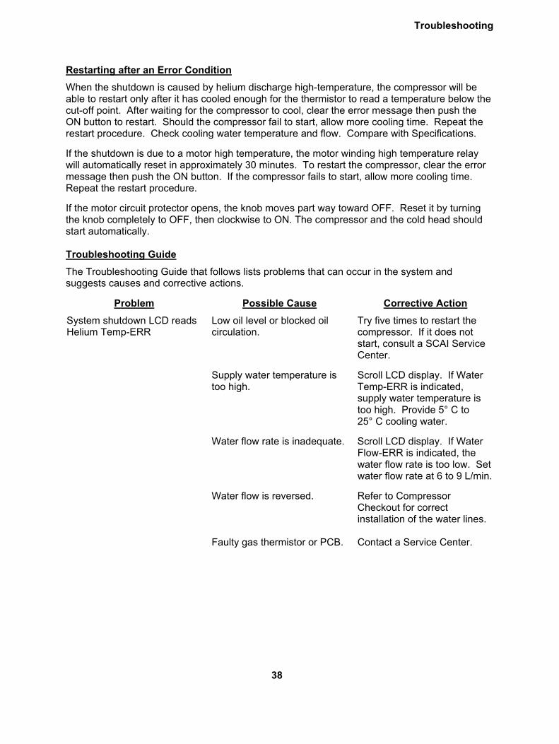
Restarting after an Error Condition
When the shutdown is caused by helium discharge high-temperature, the compressor will be able to restart only after it has cooled enough for the thermistor to read a temperature below the cut-off point. After waiting for the compressor to cool, clear the error message then push the ON button to restart. Should the compressor fail to start, allow more cooling time. Repeat the restart procedure. Check cooling water temperature and flow. Compare with Specifications.
If the shutdown is due to a motor high temperature, the motor winding high temperature relay will automatically reset in approximately 30 minutes. To restart the compressor, clear the error message then push the ON button. If the compressor fails to start, allow more cooling time. Repeat the restart procedure.
If the motor circuit protector opens, the knob moves part way toward OFF. Reset it by turning the knob completely to OFF, then clockwise to ON. The compressor and the cold head should start automatically. Troubleshooting Guide
The Troubleshooting Guide that follows lists problems that can occur in the system and suggests causes and corrective actions.
Problem Possible Cause Corrective Action
System shutdown LCD reads Helium Temp-ERR
Low oil level or blocked oil circulation.
Try five times to restart the compressor. If it does not start, consult a SCAI Service Center.
Supply water temperature is too high.
Scroll LCD display. If Water Temp-ERR is indicated, supply water temperature is too high. Provide 5° C to 25° C cooling water.
Water flow rate is inadequate. Scroll LCD display. If Water Flow-ERR is indicated, the water flow rate is too low. Set water flow rate at 6 to 9 L/min.
Water flow is reversed. Refer to Compressor Checkout for correct installation of the water lines.
Faulty gas thermistor or PCB. Contact a Service Center.
38

Troubleshooting
Problem Possible Cause Corrective Action
System shutdown LCD reads Motor Temp-ERR
Compressor motor windings high temperature switch opens. Compressor motor windings have overheated.
Scroll LCD display. If Water Temp-ERR or Water Flow-ERR is indicated, cooling water is inadequate. Refer to Specifications. Consult a Service Center if the problem persists. Allow about 30 minutes for the windings to cool enough for the switch to reset.
Reversed phase or loss of phase.
Check mains power.
Fuse(s) opened or poor power quality.
If power checks indicate utilities are within specifications, check fuses.
System shutdown LCD reads Phase Seq-ERR.
Fuse(s) opened or poor power quality.
If power checks indicate utilities are within specifications, check fuses.
System shutdown LCD Return Press-ERR.
Compressor has lost helium charge.
Refer to Charging or Venting, Gas Clean-up and Leak Check in the Service Manual.
System shutdown LCD reads FAIL instead of ERR.
Sensor is disconnected. Contact a Service Center.
Compressor and cold head motor do not start when the start switch on the compressor is pushed.
No electrical power.
Check that the power source is on and connected.
Wrong voltage. Compare customer’s electric service with system specifications.
Main power phase sequence is wrong.
Interchange any two- (2) incoming power leads (except ground.
Defective component in the power circuit.
Refer to Compressor Motor troubleshooting in this section.
Tripped motor circuit protector on the front panel.
Reset the protector by turning the knob to OFF, then turn the knob clockwise to ON. Compare electric service with the system specifications. Consult a Service Center if the problem persists.
39

Troubleshooting
Problem Possible Cause Corrective Action
Compressor starts but shuts down later.
Insufficient coolant for the compressor.
Check the coolant flow and temperature. Refer to Specifications.
System starts but gas pressure is abnormally high or low.
Wrong equalization pressure. Refer to Specifications and the section on Charging or Venting.
Gas line couplings are not fully engaged.
Be sure that all gas couplings are fully engaged and torqued.
Gas lines are connected wrong.
Reconnect. See the Installation section.
Cold head motor does not start when the compressor starts.
Cold head cable is not connected.
Stop the compressor. Connect the cable. Check connections at the cold head and at the compressor.
Open circuit in the cold head cable.
Disconnect the cable. Check each conductor for continuity. Replace the cable if necessary.
FU-4, FU-5 or FU-6 fuse is blown.
Contact a Service Center to have a qualified electrical technician replace the fuse inside the electrical enclosure.
Cold head motor hums but does not start.
Open circuit in the cold head cable.
Disconnect the cable. Check each conductor for continuity. Replace the cable if necessary
Valve disc stalled on the valve stem.
Check the system equalization pressure. Consult a Service Center.
FU-4, FU-5 or FU-6 fuse is blown.
Contact a Service Center to have a qualified electrical technician replace the fuse inside the electrical enclosure
40

Troubleshooting
Problem Possible Cause Corrective Action
Cold head motor runs, but there is no cooldown.
Gas line couplings are not fully engaged.
Be sure that all gas couplings are fully engaged and torqued.
Gas lines are connected wrong.
Reconnect. See the Installation section.
Intermittent operation. Compressor is cycling on and off.
Check input power, coolant flow and temperature. Compare with Specifications.
Loss of refrigeration capacity. Compressor malfunction.
Check input power, coolant flow and temperature, and equalization pressure. Compare with Specifications.
Compressor shuts down, LCD display is blank
FU-1, FU-2, or FU-3 fuse is blown.
Contact a Service Center to have a qualified electrical technician replace the fuse inside the electrical enclosure.
Malfunctioning control boards. Contact a Service Center.
Compressor is unresponsive to remote (DB-25 diagnostic interface) control
Configuration selector switch is in the wrong position.
Turn off power and move the switch to the correct position. See Diagnostic Interface Connection in the Installation section of this manual.
Remote status signals (DB-25 diagnostic interface) do not match actual status
Configuration selector switch is in the wrong position or was in the wrong position when power was supplied to the controller.
Turn off power and move the switch to the correct position. See Diagnostic Interface Connection in the Installation section of this manual.
LCD display shows configuration error
Configuration selector switch is in the wrong position or was in the wrong position when power was supplied to the controller.
Turn off power and move the switch to the correct position. See Diagnostic Interface Connection in the Installation section of this manual.
41

Troubleshooting
Figure 12 F-70H Compressor Wiring Diagram
42

Troubleshooting
Figure 13 F-70H Compressor Wiring Schematic
43

Troubleshooting
Figure 14 F-70L Compressor Wiring Diagram
44

Troubleshooting
Figure 15 F-70L Compressor Wiring Schematic
45

Troubleshooting
Diagnostic Interface Connector Pin Functions
Pin # Function
3 Reset. System error conditions are cleared by momentary application of a +24VDC, 2 mA signal to this pin.
4 Cold head pause. The cold head only will turn off while a +24VDC, 2 mA signal is applied to this pin if the system was turned on remotely (pin 6). The cold head will restart when the signal is removed.
6 System ON/OFF. The compressor and cold head will turn on when +24VDC, 2 mA signal is applied to this pin. They will turn off when the signal is removed.
7 Remote control ON/OFF high. Firmware not currently responsive to signal.
8 Remote control ON/OFF low. Firmware not currently responsive to signal.
10 Compressor return pressure analog value, 0.5-4.5 VDC linear relative to pin 24: PSI Absolute = 125 x (volts) – 47.8
11 Not active. 0 VDC, 20 mA max. signal.
12 Protective earth ground
13 Protective earth ground
14 High water temp. If the temperature of the water supply to the heat exchanger is too high, this pin will carry a +24VDC, 20 mA max. signal.
15 Low water flow. If the temperature of the water leaving the heat exchanger is too high, this pin will carry a +24VDC, 20 mA max. signal.
16 Low pressure shutdown. On a compressor return low pressure error (<15 psig) this pin will carry a +24 VDC, 20 mA max. signal.
17 Power error. On a phase or fuse error, this pin will carry a +24VDC, 20 mA max. signal.
18 Gas temp error. On a high helium gas discharge temperature error, this pin will carry a +24VDC, 20 mA max. signal.
19 Run status. When the compressor and cold head are running or the compressor is running with the cold head paused, this pin will carry a +24VDC, 20 mA max. signal.
20 Motor winding temperature error. On a high compressor motor winding temperature error, this pin will carry a +24VDC, 20 mA max. signal.
24 0 VDC, 100 mA signal power source.
25 +24VDC, 100mA signal power source.
Table 1 Diagnostic Interface Connector Pin Functions, Configuration Mode 1
46

Troubleshooting
Pin # Function
4 Cold head pause. The cold head only will turn off while a 0 VDC, 2 mA signal is applied to this pin if Remote Control is ON (pins 7 and 8) and System is ON (pin 6). The cold head will restart when the signal is removed.
5 Reset. System error conditions are cleared by momentary application of a 0 VDC, 2 mA signal to this pin.
6 System ON/OFF. The compressor and cold head will turn on when 0 VDC, 2 mA signal is applied to this pin. They will turn off when the signal is removed. Input is opto-isolated.
7 Remote control ON/OFF high. System control is responsive only to DB-25 control inputs (and not responsive to front panel ON/OFF buttons) when electrical continuity (<20 ohms) is applied between pins 7 and 8. When continuity is removed, system control is responsive only to front panel ON/OFF buttons.
8 Remote control ON/OFF low. See pin 7 description.
10 Compressor return pressure analog value, 0.5-4.5 VDC linear relative to pin 24: PSI Absolute = 125 x (volts) – 47.8
11 Not active. 0 VDC, 20 mA max. signal.
12 Protective earth ground
13 Protective earth ground
14 Run status. When the compressor and cold head are running or the compressor is running with the cold head paused, this pin will carry a 0 VDC, 20 mA max. signal.
15 Motor winding temperature error. On a high compressor motor winding temperature error, this pin will carry a 0 VDC, 20 mA max. signal.
16 Solenoid open. When the internal bypass solenoid valve is open, this pin will carry a 0 VDC, 20 mA max. signal.
17 Power error. On a phase or fuse error, this pin will carry a 0 VDC, 20 mA max. signal.
18 High water temp. If the temperature of the water supply to the heat exchanger is too high, this pin will carry a 0 VDC, 20 mA max. signal.
19 Low water flow. If the temperature of the water leaving the heat exchanger is too high, this pin will carry a 0 VDC, 20 mA max. signal.
21 Gas temp error. On a high helium gas discharge temperature error, this pin will carry a 0 VDC, 20 mA max. signal.
23 Low pressure shutdown. On a compressor return low pressure error (<15 psig) this pin will carry a 0 VDC, 20 mA max. signal
24 0 VDC signal power source.
25 +24VDC, 100mA signal power source.
Table 2 Diagnostic Interface Connector Pin Functions, Configuration Mode 2
47

(This page is intentionally blank.)
48