Embed Size (px)
Citation preview

1
IMPORTANT:
Go to www.extron.com for the
complete user guide, installation
instructions, and specifications.
12A MAXPOWER OUTPUT 12A MAX
TXLAN
RX +5V
INPUT IR
COM100-120VAC 50/60Hz
IN S G
US
LISTED 17TTAUDIO/VIDEO
APARATUS
®
IPL T PC1
R100
TX
RX
INPUT
IR
LINK
ACT
POWER
10A MAXPOWER OUTPUT 10A MAX
TXLAN
RX +5V
INPUT IR
COM200-240V ~ 50/60Hz
IN S G
US
LISTED 17TTAUDIO/VIDEO
APARATUS
®
IPL T PC1
R100
TX
RX
INPUT
IR
LINK
ACT
POWER
SMP 111STREAMING MEDIA PROCESSOR
INPUT OUT
HDCP
HDMIHDMI LINE HDMI
CLIP
AUDIOCONFIG
USB STORAGEALARMMARK
RxTx G
RS-232 CONTROLRESET
+12V1.0A MAX
INPUTS OUTPUT REMOTE
SMP 111100-240V 0.7A
50-60 Hz LAN
USB STORAGE
HDMI HDMI
L
AUDIOLINE R
USB STORAGE
MARK
RECORD
ExtronStudioStation 100Streaming Media Processor
ExtronSMB 212Two-gang Surface Mount Box
Extron RCP 101 EURemote ControlPanel
ExtronIPL T PC1IP Link AC Power and Device Controller
OR
ExtronIPL T PC1iIP Link AC Power and Device Controller
USB Drive
Wireless Microphone System (not included)
Audio
USB Power
Power
Crossover
HDMI
Camera & Lights(not included)
POWER STANDBYPOWER STANDBY
1
3 4 5 6 7 8910 7
11
10
2Extron
StudioStation • Installation Guide
The Extron StudioStation is an easy-to-use single button recording system, which allows users to create recordings with the touch of a button. The system integrates the StudioStation 100 Streaming Media Processor, a high definition recording and streaming device, the RCP 101 EU for remote recording controls, the IPL T PC1 for remote AC power, and the SMB 212 to surface mount the RCP 101 EU. The StudioStation 100 records MP4, M4V and M4A files of full screen HDMI video channel with mixed audio, and metadata. The StudioStation is ideal for installation beneath conference tables and in lecterns.
The StudioStation turns the power output of the IPL T PC1 (or optional IPL T PCS4) on and off when it is triggered by thumb drive detection on the RCP 101 EU. When the user inserts a properly formatted USB drive into the RCP 101 EU, the AC power port of the IPL T PC1 turns on to power up all the attached recording equipment such as the camera, studio lights, and microphone. Conversely, when the USB thumb drive is removed from the RCP 101 EU, the AC power port of the IPL T PC1 automatically powers OFF the equipment.
Items included in StudioStation are:
• 1 StudioStation 100 • 1 RCP 101 EU • 1 Flex55 102 • (1) 15’ (4.5 m) USB Mini-B to USB type A cable
• 1 IPL T PC1 • 1 SMB 212 • 1 Blank plate • (1) 6’ (1.8 m) RJ-45 network crossover cable
NOTES: • Throughout this guide, the IPL T PC1 refers to either the IPL T PC1 or IPL T PC1i.
• For full device configuration and operation details, see the StudioStation User Guide at www.extron.com or StudioStation Help File.
Installation Diagram
Figure 1. Typical StudioStation Application
2
StudioStation • Setup Guide (Continued)
BBCC
AA
Installation
To install the StudioStation devices (see figure 1 on the previous page):
1 Decide where you would like the RCP 101 EU controller located and mount the SMB 212 in that location (see the SMB 200 Setup Guide provided with the SMB 212).
2 Install the RCP 101 EU controller into the SMB 212 using the Flex55 Mounting Kit (see figure 2).
a. Install Flex 55 2-gang frame into the SMB 212 (see figure 2, 1 and 2).
b. Snap the RCP 101 EU into the Flex55 2-gang mounting frame (see figure 2, 3).
c. Snap the blank plate into the empty slot of the 2-gang Flex55 2-gang frame.
SMB 212
MountingBracket
MountingFrame
Flex 55 100Mounting Kit
MountingBracket
Secure the mounting bracket to the box using the provided M3 screws.
Position the mounting frame on the mounting bracket.
2
Connect cables to the RCP 101 EU and snapinto the mounting bracket.
3RCP 101 EU
Blank Plate
USB STORAGEMARK
Extron
Extron
RECORD
1
kk Pl t
Figure 2. Flex55 Module Installation Diagram
3 Connect the HDMI cable from the camera (not included) into the HDMI input on the StudioStation 100.
4 Connect the 3.5 mm 5-pole captive screw connector from the audio system (not included) into the Audio Input on the StudioStation 100.
5 Connect the RCP 101 EU to the StudioStation 100 using the provided 15 foot (4.5 meter) USB Mini-B to USB type A cable.
a. Insert the USB Mini-B connector into the USB port on the RCP 101 EU rear panel (see the image on the right, C).
b. Use a zip tie to secure the USB cable to the anchor (A).
c. Connect the other end of the cable to the Control USB port on the rear panel of the StudioStation 100 (see figure 1, 5 on the previous page).
To increase the distance up to 300 feet (100 m), use an Extron Extender Plus Series twisted pair extender
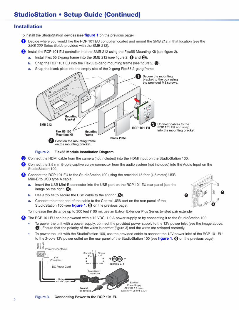
6 The RCP 101 EU can be powered with a 12 VDC, 1.0 A power supply or by connecting it to the StudioStation 100.
• To power the unit with a power supply, connect the provided power supply to the 12V power inlet (see the image above, B). Ensure that the polarity of the wires is correct (figure 3) and the wires are stripped correctly.
• To power the unit with the StudioStation 100, use the provided cable to connect the 12V power inlet of the RCP 101 EU to the 2-pole 12V power outlet on the rear panel of the StudioStation 100 (see figure 1, 6 on the previous page).
Power Receptacle
DC Power Cord
+12 VDC Input
SECTION A–A
RidgesSmooth
Power SupplyOutput Cord
AA3/16"(5 mm) Max.
PO
WE
R
1.0
A M
AX
12V
Return
Ground all devices.
1A M
AX
100-
240V
50-6
0Hz
External Power Supply
(12 VDC, 1 A max.,Extron P/N 28-071-57LF)
Figure 3. Connecting Power to the RCP 101 EU

3
ATTENTION:• Do not connect any external power supplies until you have read the Attention notifications in the Power Supply
section of the user guide for that device.• Ne branchez pas de sources d’alimentation externes avant d’avoir lu les mises en garde dans la section
« Power Supply » du guide utilisateur pour cet appareil.
7 Connect the StudioStation 100 LAN port to the IPL T PC1 LAN port (see figure 1 on page 1) using the included NETXC M-M 6 foot (1.8 meter) RJ-45 network crossover cable to enable the IPL T PC1 to power on and off the connected recording equipment such as the camera, studio lights, and microphone, when a USB drive is inserted into the RCP 101 EU USB port.
• If the crossover cable is used, no further configuration is required.
• If a straight-through cable is used and the StudioStation and PC1 are connected through a network, follow these configuration steps:
a. Configure the IP address of the IPL T PC1 via the embedded web page.
• If you do not know the IP address, use the IP Link Device Manger to discover it.
• The default IP address of the IPL is 192.168.254.254.
b. Assign an Admin password to the IPL T PC1 (optional).
c. From the StudioStation 100 Web UI, on the StudioStation page, enter the IP address and the Admin password (if required) of the IPL T PC1 and test the connection (see figure 4).
• In order to enter the Web UI of the StudioStation 100, you need the IP address of the StudioStation 100.
• The default IP address of the StudioStation 100 is 192.168.254.253
Figure 4. Test Connection on the StudioStation Page
8 Connect the IEC power cable from the lights into the IEC Power outlet of the IPL T PC1 to automatically power the lights on and off when a USB drive is inserted into the USB port on the RCP 101 EU.
9 Connect an optional HDMI display into the HDMI output to preview the recording.
¢ Connect the provided IEC cables:
a. Into the IPL T PC1 and a power source.
b. Into the StudioStation 100 and a power source.
c. Verify the front panel buttons and LCDs illuminate.
£ Insert a USB drive into the USB port on the RCP 101 EU.
a. The StudioStation 100 detects the USB drive inserted into the RCP 101 EU and sends a command to the IPL T PC1 to turn on the power outlet.
NOTE: By default, the StudioStation 100 records to the RCP 101 EU USB drive.
b. The IPL T PC1 powers ON the attached recording devices.
NOTE: When the USB drive is removed from the RCP 101 EU, the Studio Station 100 sends a command to turn OFF the IPL T PC1 power output. All attached recording devices are powered OFF.
¤ Configure the StudioStation 100 (optional). Configuration is only available when connected through a network.
a. Configure the metadata on the Metadata page (see figure 5) in the StudioStation 100 Web UI.
Figure 5. Configure Metadata on the Encoding & Metadata Page

4
68-3134-51 Rev. B09 17
Extron Headquarters+800.633.9876 Inside USA/Canada Only
Extron USA - West Extron USA - East+1.714.491.1500 +1.919.850.1000
+1.714.491.1517 FAX +1.919.850.1001 FAX
Extron Europe+800.3987.6673
Inside Europe Only
+31.33.453.4040
+31.33.453.4050 FAX
Extron Asia+65.6383.4400
+65.6383.4664 FAX
Extron Japan+81.3.3511.7655
+81.3.3511.7656 FAX
Extron China+86.21.3760.1568
+86.21.3760.1566 FAX
Extron Middle East+971.4.299.1800
+971.4.299.1880 FAX
Extron Australia+61.8.8113.6800+61.8.8351.2511 FAX
Extron India1800.3070.3777
(Inside India Only)
+91.80.3055.3777
+91.80.3055.3737 FAX
© 2017 Extron Electronics All rights reserved. All trademarks mentioned are the property of their respective owners. www.extron.com
b. Configure the recording resolution in the Recording panel on the Encoding page (see figure 6) in the StudioStation 100 Web UI.
Figure 6. Configure Recording Resolution on the Encoding Page
c. Optionally, configure the file publish destination in the Publishing Destination Configuration panel on the Publish Settings page (see figure 7) in the StudioStation 100 Web UI.
NOTE: If you connected the StudioStation 100 LAN port to the IPL T PC1 LAN port with the crossover cable, in 7 on the previous page, you cannot configure the file publish destination.
Figure 7. Publishing Destination Configuration Panel on the Publish Settings Page
Making a Recording
The StudioStation 100 and RCP 101 EU are ready to record. Follow these instructions to make a recording using the RCP 101 EU (see the image on the right):
1. Insert a USB drive into the USB port (E) on the RCP 101 EU.
2. Use the RCP 101 EU to start a recording by pressing the Record button (A).
3. Press the Mark button (D) to add a chapter marking (optional).
4. Pause the recording by pressing the Pause button (C).
5. Restart the recording by pressing the Pause button (C) a second time or by pressing the Record button (A).
6. End the recording by pressing the Stop button (B).
MARK
RECORD
USB STORAGE
Extron
AA
BB
CC DD
EE
Default Recording Setting
Recording Files: Video File
Default Preset: 720p High
Audio Bitrate: 192 Kbps
Audio Output: Mixed
Audio Delay: 0 ms
Resolution: 1280x720
Frame rate: 30 fps
GOP Length: 30
Video bit rate: 5000
Rate Control: VBR
H.264 Profile: High
Profile Level: 3.1