Embed Size (px)
Citation preview
D. Petrašinović et al. Proširena metoda konačnih elemenata (XFEM) u procjeni zamornog vijeka duraluminijske ramenjače aviona
Tehnički vjesnik 19, 3(2012), 557-562 557
ISSN 1330-3651 UDC/UDK 620.178.3.191.33:629.7.025.8]:519.63
EXTENDED FINITE ELEMENT METHOD (XFEM) APPLIED TO AIRCRAFT DURALUMIN SPAR FATIGUE LIFE ESTIMATION Danilo Petrašinović, Boško Rašuo, Nikola Petrašinović
Original scientific paper In the present work, duralumin aircraft spar fatigue life is evaluated by extended finite element method (XFEM) under cyclic loading condition. The effect of the crack growth on the fatigue life of aircraft spar is discussed in detail. The values of stress intensity factors (SIFs) are extracted from the XFEM solution. Standard Paris fatigue crack growth law (currently, the only one incorporated in Abaqus) is used for the fatigue life estimation. Obtained results are compared with previously obtained experimental results. Keywords: Abaqus, aircraft spar, crack growth, fatigue life, stress intensity factor-SIF, XFEM
Proširena metoda konačnih elemenata (XFEM) u procjeni zamornog vijeka duraluminijske ramenjače aviona
Izvorni znanstveni članak U ovom radu prikazano je određivanje zamornog vijeka duraluminijske ramenjače aviona primjenom proširene metode konačnih elemenata, pod utjecajem cikličkog opterećenja. Utjecaj širenja pukotina na zamorni vijek ramenjače krila aviona opisan je detaljno. Prikazane su vrijednosti dobivenih koeficijent intenzivnosti naprezanja primjenom proširene metode konačnih elemenata. Standardna Parisova formula za određivanje putanje pukotine (trenutno jedina integrirana u Abaqusu) korištena je za dobivanje zamornog vijeka ramenjače. Dobiveni numerički rezultati uspoređeni su s prethodno dobivenim eksperimentalnim rezultatima.
Ključne riječi: Abaqus, koeficijent intenzivnosti naprezanja, PMKE, ramenjača krila aviona, rast pukotine, zamorni vijek
1 Introduction
Today, aerospace engineeres are making the greatest effort to understand and predict fatigue crack growth. It has been widely accepted that the small crack propagation takes up most of the fatigue life time, especially for the cleaner materials of high surface quality in aerospace structures [1, 2, 3], such as the wing spar.
A wing is essentially a beam that transmits the entire applied air load to the central attachment to the fuselage. The spar presents primary structural part of aircraft wing, which means that if failure of a structural component endangers the aircraft, the component is referred to as a primary structure. So, the analysis of wing spar fatigue crack growth is very important to ensure the reliability under cyclic loading conditions.
In the field of fracture mechanics, in the past few decades, many methods for crack growth simulation in various structures have been developed. Some of these methods are: the boundary element method (BEM) [4, 5], meshfree methods [6, 7, 8], the finite element method (FEM) [9 ÷ 12], and the finite difference method (FDM).
The XFEM [13,14] still presents a new method that has not yet been fully affirmed. In order to be generally accepted, it still has to be "proven" in practice. This means that the results obtained using the XFEM for the complex 3D geometry still cannot be taken into account without experimental results, so the example of the calculation of fatigue life, which we present here, should contribute to making more objective judgment of this method usefulness. 2 Experimental testing The purpose of the test was to evaluate the behavior of the aircraft spar, made in aluminum 2024-T3 [15], under cycling loading. The test specimen is full scale and
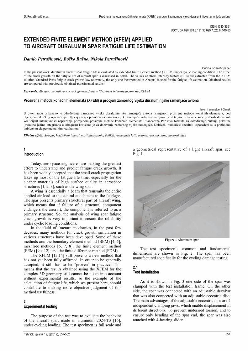
a geometrical representative of a light aircraft spar, see Fig. 1.
Figure 1 Aluminum spar
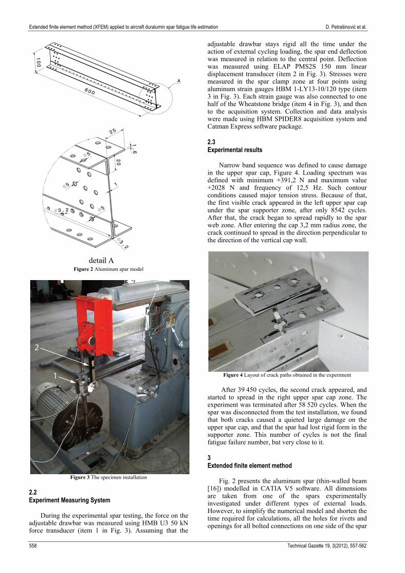
The test specimen’s common and fundamental dimensions are shown in Fig. 2. The spar has been manufactured specifically for the cycling damage testing. 2.1 Test installation
As it is shown in Fig. 3 one side of the spar was clamped with the test installation frame. On the other side, the spar was connected with an adjustable drawbar that was also connected with an adjustable eccentric disc. The main advantages of the adjustable eccentric disc are 4 independent clamping jaws, which enable displacement in different directions. To prevent undesired torsion, and to ensure only bending of the spar end, the spar was also attached with 4-bearing slider.
Extended finite element method (XFEM) applied to aircraft duralumin spar fatigue life estimation D. Petrašinović et al.
558 Technical Gazette 19, 3(2012), 557-562
Figure 2 Aluminum spar model
Figure 3 The specimen installation
2.2 Experiment Measuring System
During the experimental spar testing, the force on the adjustable drawbar was measured using HMB U3 50 kN force transducer (item 1 in Fig. 3). Assuming that the
adjustable drawbar stays rigid all the time under the action of external cycling loading, the spar end deflection was measured in relation to the central point. Deflection was measured using ELAP PMS2S 150 mm linear displacement transducer (item 2 in Fig. 3). Stresses were measured in the spar clamp zone at four points using aluminum strain gauges HBM 1-LY13-10/120 type (item 3 in Fig. 3). Each strain gauge was also connected to one half of the Wheatstone bridge (item 4 in Fig. 3), and then to the acquisition system. Collection and data analysis were made using HBM SPIDER8 acquisition system and Catman Express software package. 2.3 Experimental results Narrow band sequence was defined to cause damage in the upper spar cap, Figure 4. Loading spectrum was defined with minimum +391,2 N and maximum value +2028 N and frequency of 12,5 Hz. Such contour conditions caused major tension stress. Because of that, the first visible crack appeared in the left upper spar cap under the spar supporter zone, after only 8542 cycles. After that, the crack began to spread rapidly to the spar web zone. After entering the cap 3,2 mm radius zone, the crack continued to spread in the direction perpendicular to the direction of the vertical cap wall.
Figure 4 Layout of crack paths obtained in the experiment
After 39.450 cycles, the second crack appeared, and started to spread in the right upper spar cap zone. The experiment was terminated after 58.520 cycles. When the spar was disconnected from the test installation, we found that both cracks caused a quieted large damage on the upper spar cap, and that the spar had lost rigid form in the supporter zone. This number of cycles is not the final fatigue failure number, but very close to it. 3 Extended finite element method
Fig. 2 presents the aluminum spar (thin-walled beam [16]) modelled in CATIA V5 software. All dimensions are taken from one of the spars experimentally investigated under different types of external loads. However, to simplify the numerical model and shorten the time required for calculations, all the holes for rivets and openings for all bolted connections on one side of the spar
D. Petrašinović et al. Proširena metoda konačnih elemenata (XFEM) u procjeni zamornog vijeka duraluminijske ramenjače aviona
Tehnički vjesnik 19, 3(2012), 557-562 559
were removed from the modelled spar geometry, before it was imported into Abaqus. The calculation was made by using MorfeoCrack software for Abaqus [17].
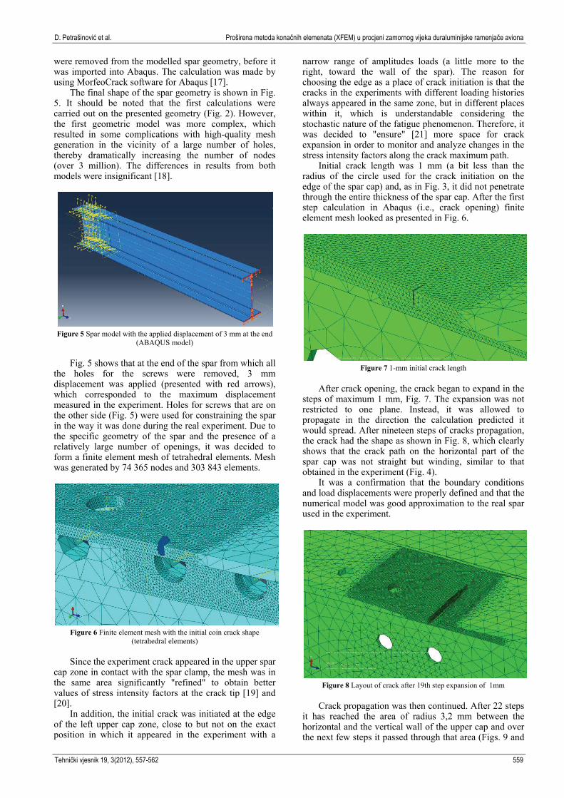
The final shape of the spar geometry is shown in Fig. 5. It should be noted that the first calculations were carried out on the presented geometry (Fig. 2). However, the first geometric model was more complex, which resulted in some complications with high-quality mesh generation in the vicinity of a large number of holes, thereby dramatically increasing the number of nodes (over 3 million). The differences in results from both models were insignificant [18].
Figure 5 Spar model with the applied displacement of 3 mm at the end
(ABAQUS model)
Fig. 5 shows that at the end of the spar from which all
the holes for the screws were removed, 3 mm displacement was applied (presented with red arrows), which corresponded to the maximum displacement measured in the experiment. Holes for screws that are on the other side (Fig. 5) were used for constraining the spar in the way it was done during the real experiment. Due to the specific geometry of the spar and the presence of a relatively large number of openings, it was decided to form a finite element mesh of tetrahedral elements. Mesh was generated by 74.365 nodes and 303.843 elements.
Figure 6 Finite element mesh with the initial coin crack shape
(tetrahedral elements)
Since the experiment crack appeared in the upper spar
cap zone in contact with the spar clamp, the mesh was in the same area significantly "refined" to obtain better values of stress intensity factors at the crack tip [19] and [20].
In addition, the initial crack was initiated at the edge of the left upper cap zone, close to but not on the exact position in which it appeared in the experiment with a
narrow range of amplitudes loads (a little more to the right, toward the wall of the spar). The reason for choosing the edge as a place of crack initiation is that the cracks in the experiments with different loading histories always appeared in the same zone, but in different places within it, which is understandable considering the stochastic nature of the fatigue phenomenon. Therefore, it was decided to "ensure" [21] more space for crack expansion in order to monitor and analyze changes in the stress intensity factors along the crack maximum path.
Initial crack length was 1 mm (a bit less than the radius of the circle used for the crack initiation on the edge of the spar cap) and, as in Fig. 3, it did not penetrate through the entire thickness of the spar cap. After the first step calculation in Abaqus (i.e., crack opening) finite element mesh looked as presented in Fig. 6.
Figure 7 1-mm initial crack length
After crack opening, the crack began to expand in the steps of maximum 1 mm, Fig. 7. The expansion was not restricted to one plane. Instead, it was allowed to propagate in the direction the calculation predicted it would spread. After nineteen steps of cracks propagation, the crack had the shape as shown in Fig. 8, which clearly shows that the crack path on the horizontal part of the spar cap was not straight but winding, similar to that obtained in the experiment (Fig. 4).
It was a confirmation that the boundary conditions and load displacements were properly defined and that the numerical model was good approximation to the real spar used in the experiment.
Figure 8 Layout of crack after 19th step expansion of 1mm
Crack propagation was then continued. After 22 steps it has reached the area of radius 3,2 mm between the horizontal and the vertical wall of the upper cap and over the next few steps it passed through that area (Figs. 9 and
Extended finite element method (XFEM) applied to aircraft duralumin spar fatigue life estimation D. Petrašinović et al.
560 Technical Gazette 19, 3(2012), 557-562
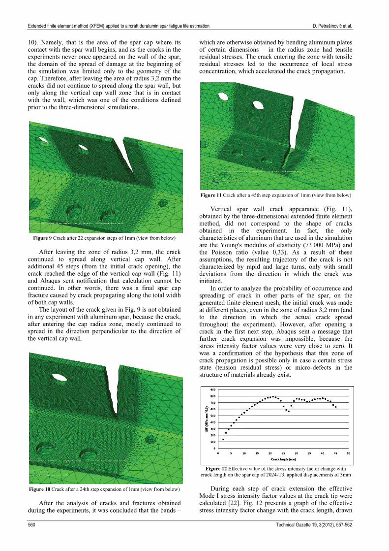
10). Namely, that is the area of the spar cap where its contact with the spar wall begins, and as the cracks in the experiments never once appeared on the wall of the spar, the domain of the spread of damage at the beginning of the simulation was limited only to the geometry of the cap. Therefore, after leaving the area of radius 3,2 mm the cracks did not continue to spread along the spar wall, but only along the vertical cap wall zone that is in contact with the wall, which was one of the conditions defined prior to the three-dimensional simulations.
Figure 9 Crack after 22 expansion steps of 1mm (view from below)
After leaving the zone of radius 3,2 mm, the crack
continued to spread along vertical cap wall. After additional 45 steps (from the initial crack opening), the crack reached the edge of the vertical cap wall (Fig. 11) and Abaqus sent notification that calculation cannot be continued. In other words, there was a final spar cap fracture caused by crack propagating along the total width of both cap walls.
The layout of the crack given in Fig. 9 is not obtained in any experiment with aluminum spar, because the crack, after entering the cap radius zone, mostly continued to spread in the direction perpendicular to the direction of the vertical cap wall.
Figure 10 Crack after a 24th step expansion of 1mm (view from below) After the analysis of cracks and fractures obtained during the experiments, it was concluded that the bands –
which are otherwise obtained by bending aluminum plates of certain dimensions – in the radius zone had tensile residual stresses. The crack entering the zone with tensile residual stresses led to the occurrence of local stress concentration, which accelerated the crack propagation.
Figure 11 Crack after a 45th step expansion of 1mm (view from below)
Vertical spar wall crack appearance (Fig. 11), obtained by the three-dimensional extended finite element method, did not correspond to the shape of cracks obtained in the experiment. In fact, the only characteristics of aluminum that are used in the simulation are the Young's modulus of elasticity (73.000 MPa) and the Poisson ratio (value 0,33). As a result of these assumptions, the resulting trajectory of the crack is not characterized by rapid and large turns, only with small deviations from the direction in which the crack was initiated.
In order to analyze the probability of occurrence and spreading of crack in other parts of the spar, on the generated finite element mesh, the initial crack was made at different places, even in the zone of radius 3,2 mm (and to the direction in which the actual crack spread throughout the experiment). However, after opening a crack in the first next step, Abaqus sent a message that further crack expansion was impossible, because the stress intensity factor values were very close to zero. It was a confirmation of the hypothesis that this zone of crack propagation is possible only in case a certain stress state (tension residual stress) or micro-defects in the structure of materials already exist.
Figure 12 Effective value of the stress intensity factor change with
crack length on the spar cap of 2024-T3, applied displacements of 3mm
During each step of crack extension the effective Mode I stress intensity factor values at the crack tip were calculated [22]. Fig. 12 presents a graph of the effective stress intensity factor change with the crack length, drawn
D. Petrašinović et al. Proširena metoda konačnih elemenata (XFEM) u procjeni zamornog vijeka duraluminijske ramenjače aviona
Tehnički vjesnik 19, 3(2012), 557-562 561
on the basis of SIF values. The graph shows that SIF increased until the twentieth step (value of 790,442 MPa·mm0,5). At twenty-first it began to decline, which coincides with the crack entering the zone between the horizontal and vertical wall.
The effective factors value continued to decline until step 26th (when the crack finally came out of the zone of radius 3,2 mm), and then began to grow again until the value of 759,198 (twenty-ninth step), after which, until the final fracture, oscillated in a relatively narrow range of 634,529 to 768,188 MPa·mm0,5.
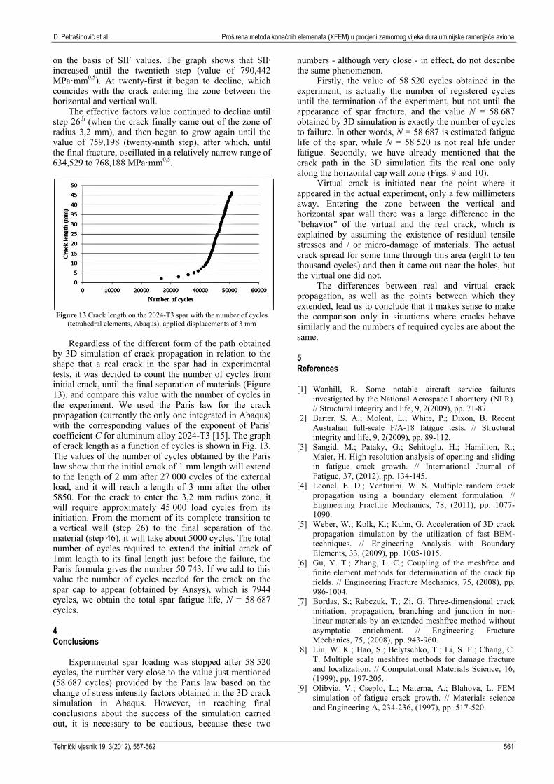
Figure 13 Crack length on the 2024-T3 spar with the number of cycles
(tetrahedral elements, Abaqus), applied displacements of 3 mm
Regardless of the different form of the path obtained by 3D simulation of crack propagation in relation to the shape that a real crack in the spar had in experimental tests, it was decided to count the number of cycles from initial crack, until the final separation of materials (Figure 13), and compare this value with the number of cycles in the experiment. We used the Paris law for the crack propagation (currently the only one integrated in Abaqus) with the corresponding values of the exponent of Paris' coefficient C for aluminum alloy 2024-T3 [15]. The graph of crack length as a function of cycles is shown in Fig. 13. The values of the number of cycles obtained by the Paris law show that the initial crack of 1 mm length will extend to the length of 2 mm after 27.000 cycles of the external load, and it will reach a length of 3 mm after the other 5850. For the crack to enter the 3,2 mm radius zone, it will require approximately 45.000 load cycles from its initiation. From the moment of its complete transition to a vertical wall (step 26) to the final separation of the material (step 46), it will take about 5000 cycles. The total number of cycles required to extend the initial crack of 1mm length to its final length just before the failure, the Paris formula gives the number 50.743. If we add to this value the number of cycles needed for the crack on the spar cap to appear (obtained by Ansys), which is 7944 cycles, we obtain the total spar fatigue life, N = 58.687 cycles. 4 Conclusions
Experimental spar loading was stopped after 58.520 cycles, the number very close to the value just mentioned (58.687 cycles) provided by the Paris law based on the change of stress intensity factors obtained in the 3D crack simulation in Abaqus. However, in reaching final conclusions about the success of the simulation carried out, it is necessary to be cautious, because these two
numbers - although very close - in effect, do not describe the same phenomenon.
Firstly, the value of 58.520 cycles obtained in the experiment, is actually the number of registered cycles until the termination of the experiment, but not until the appearance of spar fracture, and the value N = 58.687 obtained by 3D simulation is exactly the number of cycles to failure. In other words, N = 58.687 is estimated fatigue life of the spar, while N = 58.520 is not real life under fatigue. Secondly, we have already mentioned that the crack path in the 3D simulation fits the real one only along the horizontal cap wall zone (Figs. 9 and 10).
Virtual crack is initiated near the point where it appeared in the actual experiment, only a few millimeters away. Entering the zone between the vertical and horizontal spar wall there was a large difference in the "behavior" of the virtual and the real crack, which is explained by assuming the existence of residual tensile stresses and / or micro-damage of materials. The actual crack spread for some time through this area (eight to ten thousand cycles) and then it came out near the holes, but the virtual one did not.
The differences between real and virtual crack propagation, as well as the points between which they extended, lead us to conclude that it makes sense to make the comparison only in situations where cracks behave similarly and the numbers of required cycles are about the same. 5 References [1] Wanhill, R. Some notable aircraft service failures
investigated by the National Aerospace Laboratory (NLR). // Structural integrity and life, 9, 2(2009), pp. 71-87.
[2] Barter, S. A.; Molent, L.; White, P.; Dixon, B. Recent Australian full-scale F/A-18 fatigue tests. // Structural integrity and life, 9, 2(2009), pp. 89-112.
[3] Sangid, M.; Pataky, G.; Sehitoglu, H.; Hamilton, R.; Maier, H. High resolution analysis of opening and sliding in fatigue crack growth. // International Journal of Fatigue, 37, (2012), pp. 134-145.
[4] Leonel, E. D.; Venturini, W. S. Multiple random crack propagation using a boundary element formulation. // Engineering Fracture Mechanics, 78, (2011), pp. 1077-1090.
[5] Weber, W.; Kolk, K.; Kuhn, G. Acceleration of 3D crack propagation simulation by the utilization of fast BEM-techniques. // Engineering Analysis with Boundary Elements, 33, (2009), pp. 1005-1015.
[6] Gu, Y. T.; Zhang, L. C.; Coupling of the meshfree and finite element methods for determination of the crack tip fields. // Engineering Fracture Mechanics, 75, (2008), pp. 986-1004.
[7] Bordas, S.; Rabczuk, T.; Zi, G. Three-dimensional crack initiation, propagation, branching and junction in non-linear materials by an extended meshfree method without asymptotic enrichment. // Engineering Fracture Mechanics, 75, (2008), pp. 943-960.
[8] Liu, W. K.; Hao, S.; Belytschko, T.; Li, S. F.; Chang, C. T. Multiple scale meshfree methods for damage fracture and localization. // Computational Materials Science, 16, (1999), pp. 197-205.
[9] Olibvia, V.; Cseplo, L.; Materna, A.; Blahova, L. FEM simulation of fatigue crack growth. // Materials science and Engineering A, 234-236, (1997), pp. 517-520.
Extended finite element method (XFEM) applied to aircraft duralumin spar fatigue life estimation D. Petrašinović et al.
562 Technical Gazette 19, 3(2012), 557-562
[10] Zhou, F.; Molinari, J. F.; Li, Y. Three-dimensional numerical simulations of dynamic fracture in silicon carbide reinforced aluminum. // Engineering Fracture Mechanics, 71, 9(2004), pp. 1357-1378.
[11] Berković, M., Numerical Methods in Fracture Mechanics. // Structural integrity and life, 4, 2(2004), pp. 63-66.
[12] Kozak, D.; Gubeljak, N.; Konjatić, P.; Sertić, J. Yield load solutions of heterogeneous welded joints. // International journal of pressure vessels and piping, 86, 12(2009), pp. 807-812.
[13] Sabsabi, M.; Giner, E.; Fuenmayor, F. J. Experimental fatigue testing of a fretting complete contact and numerical life correlation using X-FEM. // International Journal of Fatigue, 33, 6(2011), pp. 811-822.
[14] Sukumar, N.; Chopp, D. L.; Moran, B. Extended finite element method and fast marching method for three-dimensional fatigue crack propagation. // Engineering Fracture Mechanics, 70, 1(2003), pp. 29-48.
[15] Rašuo, B.; Aircraft production technology. Faculty of Mechanical Engineering, Belgrade, 1995. (in Serbian).
[16] Živojinović, D.; Arsić, M.; Sedmak, A.; Kirin, S.; Tomić, R. Practical aspests of fail-safe design-calculation of fatigue life of cracked thin-walled structures. // Tehnički vjesnik/Technical Gazette. 18, 4 (2011), pp. 609-617.
[17] Cenaero. Morfeo/crack for Abaqus, from http://cneaero.be, accessed on 2012-05-11.
[18] Shibanuma, K.; Utsunomiya, T. Evaluation on reproduction of priori knowledge in XFEM. // Finite Elements in Analysis and Design, 47, 4(2011), pp. 424-433.
[19] Siegmund, T.; A numerical study of transient fatigue crack growth by use of an irreversible cohesive zone model. // International Journal of Fatigue, 26, 9(2004), pp. 929-939.
[20] Combescure, A.; Gravouil, A.; Gregoire, D.; Rethore, T. X-FEM a good candidate for energy conservation in simulation of brittle dynamic crack propagation. // Comput. Methods Appl. Mech. Engrg, 197, 5(2008), pp. 309-318.
[21] Grbović, A.; Rašuo, B.; Vidanović, N.; Perić, M. Simulation of Crack Propagation in Titanium Mini Dental Implants (MDI). // FME Transactions, 39, 4(2011), pp. 165-170.
[22] Berković, M.; Determination of Stress Intensity Factors Using Finite Element Method. // Structural integrity and life, 4, 2(2004), pp. 57-62.
Authors’ addresses Mr. Danilo Petrašinović, assistant University of Belgrade Faculty of Mechanical Engineering Kraljice Marije 16, Belgrade, Serbia e-mail: [email protected] Prof. dr. Boško Rašuo University of Belgrade Faculty of Mechanical Engineering Kraljice Marije 16, Belgrade, Serbia e-mail: [email protected] M. Sc. Nikola Petrašinović, PhD student University of Belgrade Faculty of Mechanical Engineering Kraljice Marije 16, Belgrade, Serbia e-mail: [email protected]


![4. XFEM による亀裂進展シミュレーション · PDF file4. xfem による亀裂 ... abaqus [15]にpu-xfem に基づくき裂解析機能を組み込むことで,効率的に3](https://img.dokumen.tips/doc/110x75/5aa80e8f7f8b9aca258b5763/4-xfem-xfem-.jpg)