Embed Size (px)
Citation preview
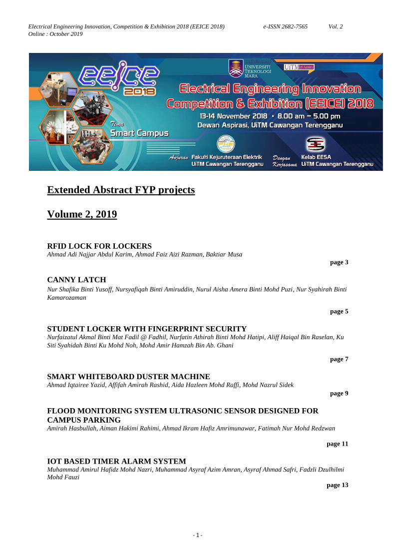
Electrical Engineering Innovation, Competition & Exhibition 2018 (EEICE 2018) e-ISSN 2682-7565 Vol. 2
Online : October 2019
- 1 -
Extended Abstract FYP projects
Volume 2, 2019
RFID LOCK FOR LOCKERS Ahmad Adi Najjar Abdul Karim, Ahmad Faiz Aizi Razman, Baktiar Musa
page 3
CANNY LATCH
Nur Shafika Binti Yusoff, Nursyafiqah Binti Amiruddin, Nurul Aisha Amera Binti Mohd Puzi, Nur Syahirah Binti
Kamarozaman
page 5
STUDENT LOCKER WITH FINGERPRINT SECURITY Nurfaizatul Akmal Binti Mat Fadil @ Fadhil, Nurfatin Athirah Binti Mohd Hatipi, Aliff Haiqal Bin Raselan, Ku
Siti Syahidah Binti Ku Mohd Noh, Mohd Amir Hamzah Bin Ab. Ghani
page 7
SMART WHITEBOARD DUSTER MACHINE Ahmad Iqtairee Yazid, Affifah Amirah Rashid, Aida Hazleen Mohd Raffi, Mohd Nazrul Sidek
page 9
FLOOD MONITORING SYSTEM ULTRASONIC SENSOR DESIGNED FOR
CAMPUS PARKING Amirah Hasbullah, Aiman Hakimi Rahimi, Ahmad Ikram Hafiz Amrimunawar, Fatimah Nur Mohd Redzwan
page 11
IOT BASED TIMER ALARM SYSTEM Muhammad Amirul Hafidz Mohd Nazri, Muhammad Asyraf Azim Amran, Asyraf Ahmad Safri, Fadzli Dzulhilmi
Mohd Fauzi
page 13
Electrical Engineering Innovation, Competition & Exhibition 2018 (EEICE 2018) e-ISSN 2682-7565 Vol. 2
Online : October 2019
- 2 -
AUTOMATIC SOCKET Muhammad Razin Aiman Rizal, Muhammad Zahran Zaidi, Muhammad Nurhazim Abdul Khalil, Mohamad Yusof
Mat Zain
page 15
TRASH CAN MONITORING USING IOT Mohammad Aiman Lakim, Muhammad Afiq Ad Wahab Rakhdi, Nur Amirah Mohd Radi, Fadzli Dzulhilmi Mohd
Fauzi
page 17
IOT CONTROLLED WATER SYSTEM USING PIR MOTION SENSOR AND VOICE
ACTIVATION Muhammad Aza Azree Shariff bin Abdul Aziz
2, Dzaki Dziauddin bin Sabaruddin
3, Kartini binti Mohammad, Wan
Ahmad Khusairi Wan Chek
page 19
AUTOMATIC PLANT WATERING AND FERTILIZING SYSTEM Muhammad Fauzan Bin Faridz, Muhammad.Fareez Bin Mohd Ainul Hakeem, Muhammad Firdaus Bin Umar, Najwa Nasuha Binti Mahzan, Haslizamri Bin Md Shariff
page 21
WI-FI CONTROLLED SMART SWITCH USING SMARTPHONE Nurul Huda Ruslan, Nurul Nadia Mokhtar, Siti Fadhilah Ibrahim, Rina Abdullah
page 23
SMART DOOR LOCK USING IOT Nor Intan Syahira Mohd Rawi, Muhammad Mirza Azmil Mazelan, Johan Naqib Faisal Johar, Mohd Nazrul
Sidek
page 25
UNIVERSAL INTEGRATED SOCKET CONTROLLED OVER IoT NETWORK
(UISCOIN) Syafiq Abdul Haizam, Muhamad Zaim Nadzaruddin, Muhammad Nur Hakim Mohamed Nizam, Mohamad Taib
Miskon
page 27

Electrical Engineering Innovation, Competition & Exhibition 2018 (EEICE 2018) e-ISSN 2682-7565 Vol. 2
Online : October 2019
- 3 -
RFID LOCK FOR LOCKERS
Ahmad Adi Najjar Abdul Karim, Ahmad Faiz Aizi Razman, Baktiar Musa
Faculty of Electrical Engineering,
Universiti Teknologi MARA, Cawangan Terengganu, Kampus Dungun
23000 Dungun, Terengganu
[email protected], [email protected]
Abstract - The security of the lockers for the UiTM campus in Dungun are known to be lacking. This results in
either the belongings of anyone using them potentially being stolen or the lockers are not used at all. Simply put it
results in either loss or wastage. The lockers we will be focusing on the lockers placed in front of laboratories and
inside the campus mosque due to the fact that they are publically used. The RFID Lock for Lockers is specifically
designed as to be implemented to these lockers. The project utilizes the already available matric card held by all
students and staff. This project is comprised of both hardware and software. An RFID reader is used to read the
data on the matric card of students and or staff member. The data is sent to the Arduino NANO which stores the ID
of the card. The servo motor then locks the locker. Thus the locker will remain locked until another card is scanned.
The Arduino NANO will compare both IDs and check if they are the same. If they are, the servo motor will unlock
the locker, but if the IDs are different the locker will remain locked. This simple system was designed to be
efficient and easy to use by anyone with a matric card.
Keywords - Lock, Locker, RFID, Matric, card.
INTRODUCTION
Universiti Teknologi MARA, Dungun has many lockers placed around the academic block, but these
lockers are never used due to missing keys to said lockers and the security risk of the keys being duplicated. Due to
these problems the lockers are no longer used. Both problems can be solved by using the matric cards of the
students as the keys for the lockers. Each matric card has a specific ID which can be used as a passcode to lock and
unlock the lockers. Students always have their matric cards on their person when going to classes that use
laboratories and can use their matric cards to lock up their belongings in the lockers for safety.
METHODOLOGY
The development of this project was divided into two main parts which are hardware and software. Both of
which would not function properly without the other operating at proper efficiency.
A. HARDWARE COMPONENTS
The components used for the system are as follow:
i. Arduino NANO
ii. 16X2 LCD
iii. RC Servo Motor
iv. MFRC522 Reader
B. SOFTWARE DEVELOPMENT
The software used was Arduino IDE [1], [2] to give the Arduino NANO instructions.
RESULT AND DICUSSION
Based on the analysis of the results from the experiments conducted, it can be concluded that Arduino
NANO can read and compare the ID of the saved memory and the ID of the card. With the two IDs the output of
the mechanism will lock and the display will show “ACCESS DENIED LOCKING” if they do not match or when
there is no ID saved the mechanism will lock after scanning the ID and the display shows “ID ACCEPTED
LOCKING”. When the two IDs match the mechanism will unlock and the display will show “ACCESS
GRANTED UNLOCKING”.
Electrical Engineering Innovation, Competition & Exhibition 2018 (EEICE 2018) e-ISSN 2682-7565 Vol. 2
Online : October 2019
- 4 -
CONCLUSIONS
In conclusion, the safety measures in using the lockers have been improved and all the problems that previously
discouraged students from using them can be overcome. The reason of this outcome is because by using a matric
card as a mechanism for locking the lockers, it provides a sense of security for the students because every matric
card has their own unique identification. Furthermore, this will also help in preventing cases of thefts from
happening. The limits of the project are based on the materials used for the locker resulting in its physical strength
as a security method.
REFERENCES
[1] Arduino Homepage, [Online] Available:http://www.arduino.cc/
[2] S. Monk, Programming Arduino: getting started with sketches. 2012
Electrical Engineering Innovation, Competition & Exhibition 2018 (EEICE 2018) e-ISSN 2682-7565 Vol. 2
Online : October 2019
- 5 -
CANNY LATCH
Nur Shafika Yusoff, Nursyafiqah Amiruddin, Nurul Aisha Amera Mohd Puzi, Nur Syahirah Kamarozaman
Faculty of Electrical Engineering,
Universiti Teknologi MARA, Cawangan Terengganu, Kampus Dungun,
23000 Dungun, Terengganu
[email protected], [email protected], [email protected],
Abstract - Nowadays people are not very concerned about safety of their premises. They tend to forget to
lock/unlock the door and to turn on/off the lamp and fan. This project is designed to lock and unlock the door
and turning on or off fan and lamp system using Android smartphone application, Bluetooth module and
Arduino board. This project is friendly designed where the users can change the password created by themselves,
as a security purpose. This project uses a Bluetooth feature in the mobile phone to automatically open the door
so that Bluetooth technology can match the phone directly with the door, the fan and the lamp. The users in this
case are the students who will have the priority to open their room. Canny latch is a word synonym for smart
lock. In another word it is the project for smart door lock.
Keywords - Arduino, Bluetooth module, servo motor, relay
INTRODUCTION
Most of the students forget to bring their keys wherever they go. Besides, they also tend to forget to
switch off the fan and lamp. So, from this project, the users can lock and unlock the door using their smart
phones. A project reported by Satyam [1] is quite similar with this project where the IoT and Bluetooth device
are used to connect the door with the smartphones. The Bluetooth device and servo motor are attached near the
door‟s lock together with the Arduino [2]. Once they are connected, they are only using a portal to lock and
unlock the door with the phones. Another project reported by T. Indeevar Reddy et al [3] using IR and LDR
sensor for automation of lights and fans. They reported to use Arduino and Internet of Things for smart homes.
Using IR sensors, the lights will automatically turn on and off according to the intensity of light. The
temperature sensor detects room temperature and turn on and off fans.
Thus, this project is designed based on the use of Bluetooth based android for smartphone to unlock and
lock the door for the security purpose of their homes. At the same time, the user can turn on/off the light and fan.
The smart phone is used to control the turning on/off for both light and fan. The advantage of using the
Bluetooth module than the WiFi module is, everyone has Bluetooth in their phones. But that is not the same case
for the WiFi module. They need to have internet access in order to use that application.
METHODOLOGY
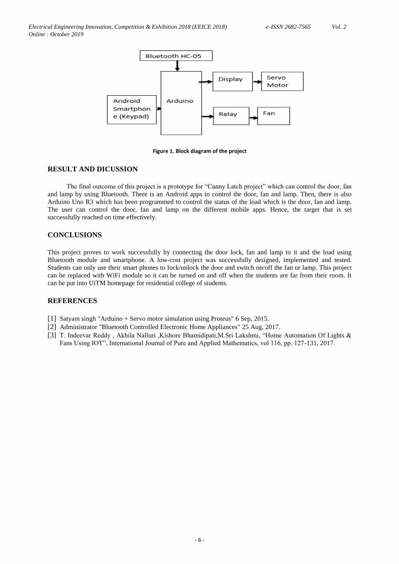
Figure 1 explains about how this project is functioning. There are two main functions which are to control
the lock/unlock the door and turn on/off the fan and lamp. This project is connected with the Internet of Things
(IoT) to interface or communicate between the input signal and the circuit for lamp/fan and the door. The
Arduino Uno is the main controller for this project. The microcontroller is used to interface between the
components and the Bluetooth module HC-05 is to connect and communicate using Android smartphone.
Electrical Engineering Innovation, Competition & Exhibition 2018 (EEICE 2018) e-ISSN 2682-7565 Vol. 2
Online : October 2019
- 6 -
Figure 1. Block diagram of the project
RESULT AND DICUSSION
The final outcome of this project is a prototype for “Canny Latch project” which can control the door, fan
and lamp by using Bluetooth. There is an Android apps to control the door, fan and lamp. Then, there is also
Arduino Uno R3 which has been programmed to control the status of the load which is the door, fan and lamp.
The user can control the door, fan and lamp on the different mobile apps. Hence, the target that is set
successfully reached on time effectively.
CONCLUSIONS
This project proves to work successfully by connecting the door lock, fan and lamp to it and the load using
Bluetooth module and smartphone. A low-cost project was successfully designed, implemented and tested.
Students can only use their smart phones to lock/unlock the door and switch on/off the fan or lamp. This project
can be replaced with WiFi module so it can be turned on and off when the students are far from their room. It
can be put into UiTM homepage for residential college of students.
REFERENCES
[1] Satyam singh "Arduino + Servo motor simulation using Proteus" 6 Sep, 2015.
[2] Administrator "Bluetooth Controlled Electronic Home Appliances" 25 Aug, 2017.
[3] T. Indeevar Reddy , Akhila Nalluri ,Kishore Bhamidipati,M.Sri Lakshmi, “Home Automation Of Lights &
Fans Using IOT”, International Journal of Pure and Applied Mathematics, vol 116, pp. 127-131, 2017.
Electrical Engineering Innovation, Competition & Exhibition 2018 (EEICE 2018) e-ISSN 2682-7565 Vol. 2
Online : October 2019
- 7 -
STUDENT LOCKER WITH FINGERPRINT SECURITY
Nurfaizatul Akmal Mat Fadil @ Fadhil, Nurfatin Athirah Mohd Hatipi, Aliff Haiqal Raselan, Ku Siti Syahidah
Ku Mohd Noh, Mohd Amir Hamzah Ab. Ghani
Faculty of Electrical Engineering,
Universiti Teknologi MARA Cawangan Terengganu, Kampus Dungun
23000 Dungun, Terengganu
Abstract - In order to have a secure locker for students, a locker using fingerprint to unlock its door is proposed.
By having this kind of locker, it is expected that the student‟s belongings can be store safely in that locker
compared to using a key or a combination of password. Every person has a unique fingerprint and cannot be
duplicated by others. Thus, the chances peoples could break the locker is low. This project used an Arduino
ATMEGA328P, servo motor, fingerprint scanner, LCD 16x2, LED, resistor and potentiometer. ATMEGA328P
is the main component in this project and acts as “brain” to control the process of input and output. As a result, a
locker with fingerprint security is more safe than using a key which can be duplicated or rusty or a combination
of password which can be hacked or forgotten.
Keywords - Arduino, servo motor, fingerprint scanner, LCD 16x2, push button
INTRODUCTION
Generally, locker is a place where we can put belongings inside it for a while. Moreover, the locker along
the area at block 13 and 14 of UiTM Dungun Terengganu has been rusty and cannot be used in many years so the
students are not preferred to keep their belongings in that locker. If we look at the lockers, many of them cannot
close properly so the chances of belonging are stolen by people is high. In addition, Arduino based Bluetooth
password lock project‟s [1] has introduced to the world a security locker which uses wireless and IoT. Indeed,
RFID is also used to open door locked system [2] One of the projects that is related to is Coolest Door Lock Ever
which this project used cyclops eyes to get access [3]. However, the main problem that this project attempts to
solve is the problems of stealing students‟ belonging. For example, before students going into lab, they put their
belongings into the locker. Unfortunately, the door locker cannot be locked and closed properly so it can be stolen
by people at any time. In addition, the objective of this project is to design a student door locker that uses
fingerprint system as the key that provides a safe space for student to store their belongings.
METHODOLOGY
Overall, there are many ways to keep the belongings in the safe zone. But for this project, it used fingerprint
scanner as the main of enhancement security. Basically, for this project, scanning fingerprint is an act to control
the access door locker. Then, it will order the servo motor to turn the blade „open‟ over the ATMEGA328P
process. In addition, LED give lights show us as a notification either it is locked or unlocked. If the light shows
red, it means the door locker is locked while if its show green, it means the blade of servo motor is unlocked.
Then there a “reset” button which reacts through push button. It is used to clear the fingerprint biometric after
the user ID. İt is relevant to use fingerprint scanner as daily life security because it give companions to people to
feel safe and protected.
RESULT AND DICUSSION
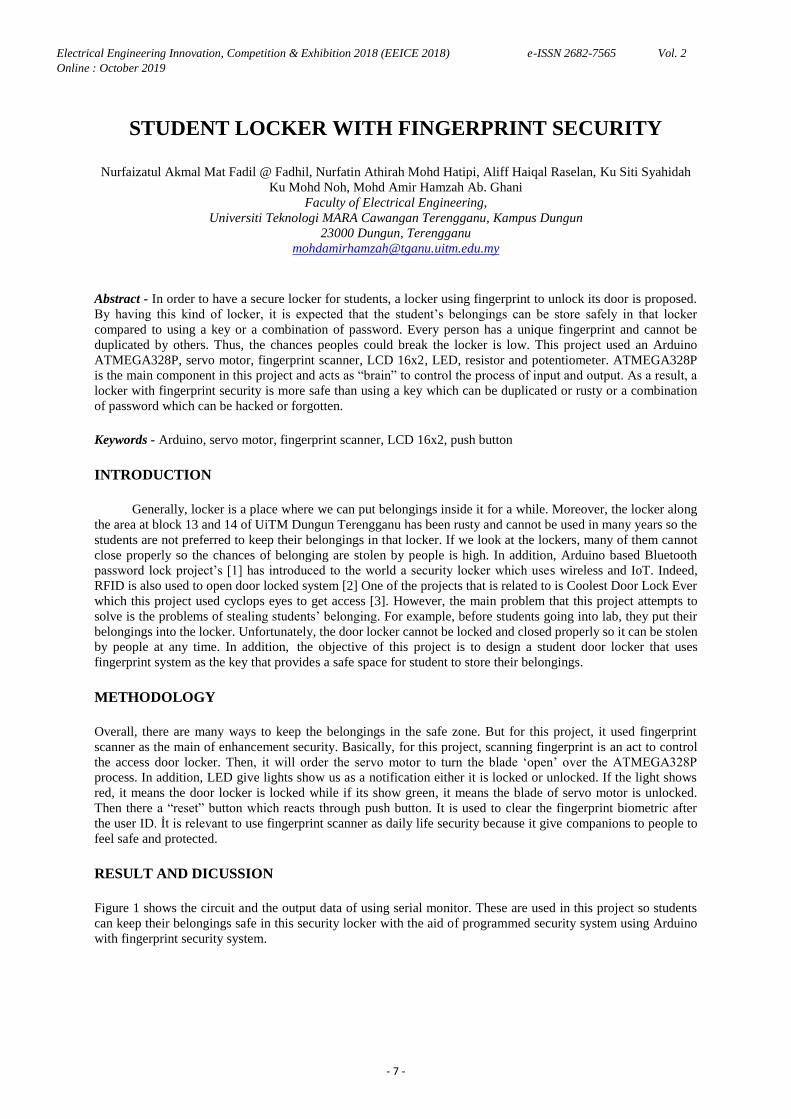
Figure 1 shows the circuit and the output data of using serial monitor. These are used in this project so students
can keep their belongings safe in this security locker with the aid of programmed security system using Arduino
with fingerprint security system.
Electrical Engineering Innovation, Competition & Exhibition 2018 (EEICE 2018) e-ISSN 2682-7565 Vol. 2
Online : October 2019
- 8 -
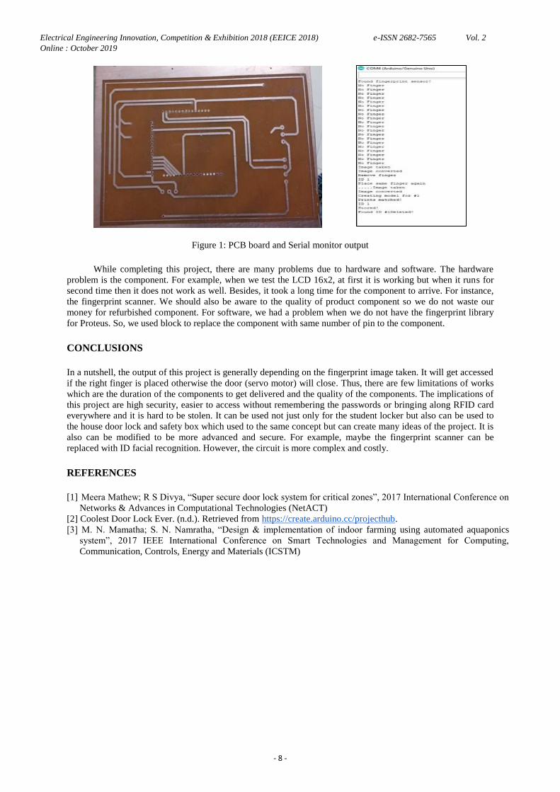
Figure 1: PCB board and Serial monitor output
While completing this project, there are many problems due to hardware and software. The hardware
problem is the component. For example, when we test the LCD 16x2, at first it is working but when it runs for
second time then it does not work as well. Besides, it took a long time for the component to arrive. For instance,
the fingerprint scanner. We should also be aware to the quality of product component so we do not waste our
money for refurbished component. For software, we had a problem when we do not have the fingerprint library
for Proteus. So, we used block to replace the component with same number of pin to the component.
CONCLUSIONS
In a nutshell, the output of this project is generally depending on the fingerprint image taken. It will get accessed
if the right finger is placed otherwise the door (servo motor) will close. Thus, there are few limitations of works
which are the duration of the components to get delivered and the quality of the components. The implications of
this project are high security, easier to access without remembering the passwords or bringing along RFID card
everywhere and it is hard to be stolen. It can be used not just only for the student locker but also can be used to
the house door lock and safety box which used to the same concept but can create many ideas of the project. It is
also can be modified to be more advanced and secure. For example, maybe the fingerprint scanner can be
replaced with ID facial recognition. However, the circuit is more complex and costly.
REFERENCES
[1] Meera Mathew; R S Divya, “Super secure door lock system for critical zones”, 2017 International Conference on
Networks & Advances in Computational Technologies (NetACT)
[2] Coolest Door Lock Ever. (n.d.). Retrieved from https://create.arduino.cc/projecthub.
[3] M. N. Mamatha; S. N. Namratha, “Design & implementation of indoor farming using automated aquaponics
system”, 2017 IEEE International Conference on Smart Technologies and Management for Computing,
Communication, Controls, Energy and Materials (ICSTM)
Electrical Engineering Innovation, Competition & Exhibition 2018 (EEICE 2018) e-ISSN 2682-7565 Vol. 2
Online : October 2019
- 9 -
SMART WHITEBOARD DUSTER MACHINE
Mohamad Amirul Farhan Abu Bakar, Luqman Amar Abdul Nasir, Nur Afifah Ali,
Wan Ahmad Khusairi Wan Chek
Faculty of Electrical Engineering,
Universiti Teknologi MARA Cawangan Terengganu,Kampus Dungun
23000 Dungun, Terengganu
[email protected], [email protected], [email protected]
Abstract - Smart Whiteboard Duster Machine is a project to speed up the time taken for erasing whiteboard.
Usually, people used to erase whiteboard manually (by hand) during the process. The difficulty experienced by
lecturer teaching and erasing at the same time inspired the idea to create this project. It will save a lot of time.
The main objective of this project is to shorten the time taken for the student and lecturer to erase the whiteboard
and use less manpower. The main component of this project is power supply, Raspberry Pi, Arduino UNO R3,
and CNC shield. When the power supply is on, the coding in Arduino UNO R3 will control the motor to move
X-axis and Y-axis. As a conclusion, this project achieves the theme of Final Year Project which is “Smart
Campus”. During the process of this project, creativity, innovative and independence are gained to increase the
self-esteem in student.
Keywords - Whiteboard eraser; Raspberry Pi and Arduino UNO R3; CNC shield; Smart Campus;
INTRODUCTION
Whiteboard is commonly used in most departments especially in educational sector. It is a medium to
present information to others so that they can easily understand the information given. Started from old
blackboard, it has been emerged into a better board such as plain whiteboard and electronic board. Even though
the type of board has changed, it still uses the same method of erasing and writing methods which is using a
small duster and common marker [1]. Considering the size of whiteboard in a certain classroom for example, it
consumes a lot of time to clean and write the whole whiteboard. It also uses a lot of manpower to clean the
whiteboard. For example, it is impossible for an elder lecturer to clean the whole whiteboard after teaching.
METHODOLOGY
The author from a study aimed at reducing the stress of manual cleaning. Whiteboard is widely known as
a medium to transfer information from the informant to receiver such as teacher teaching in school, leaders
presenting their ideas to worker and many more. Technically, it is a common device that being used by everyone.
Even though it was convenient, sometimes the board comes with a large size that it is takes longer time for the
user to erase writing on the board. The dust produced when erasing the whiteboard also can affect our health.
Based on researches carried out by Sahib Singh Dhanjal, Automatic Whiteboard Eraser was designed and
developed to overcome these problems [2]. The device is being created with a purpose to reduce time taken to
erase the whiteboard. The research‟s main purpose is to introduce the solution to the existing designs. The author
discusses disadvantages of using belt pulley-design. The device is hard to maintain if we want to keep the device
functioning efficiently. The belt also will slip out from the pulley if the device is being used for a sufficient time.
By studying the recent trend and design, authors decide to use microprocessors to act intelligently but at the
same time it could be very expensive. At the input part of this project it is controlled by an application which is
connected directly via Wi-Fi medium. This program facilitates users to control the whiteboard duster machine
via laptops with medium radius of connectivity. In the application, users can choose whether to write or erase the
whiteboard by pressing on the command button provided in the application. When the user inserts a command
such as writing, it will send the GCODE to the arduino to check whether the command is readable or not. Then
the GCODE read by the arduimo will be sent back to the database to do the action. After the database is passed,
Arduino sends the command to the motor to do their job and create motion whether to write or erase and also
draw anything based on the GCODE insert.
Electrical Engineering Innovation, Competition & Exhibition 2018 (EEICE 2018) e-ISSN 2682-7565 Vol. 2
Online : October 2019
- 10 -
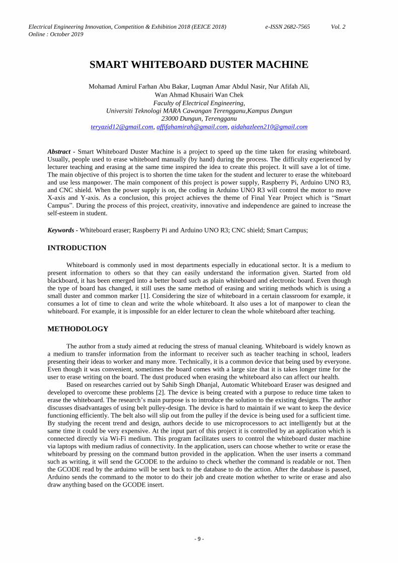
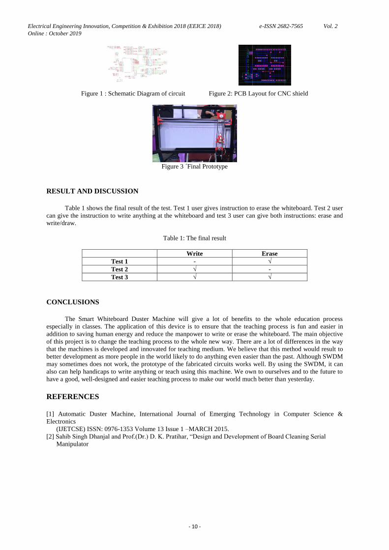
Figure 1 : Schematic Diagram of circuit Figure 2: PCB Layout for CNC shield
Figure 3 ´Final Prototype
RESULT AND DISCUSSION
Table 1 shows the final result of the test. Test 1 user gives instruction to erase the whiteboard. Test 2 user
can give the instruction to write anything at the whiteboard and test 3 user can give both instructions: erase and
write/draw.
Table 1: The final result
Write Erase
Test 1 - √
Test 2 √ -
Test 3 √ √
CONCLUSIONS
The Smart Whiteboard Duster Machine will give a lot of benefits to the whole education process
especially in classes. The application of this device is to ensure that the teaching process is fun and easier in
addition to saving human energy and reduce the manpower to write or erase the whiteboard. The main objective
of this project is to change the teaching process to the whole new way. There are a lot of differences in the way
that the machines is developed and innovated for teaching medium. We believe that this method would result to
better development as more people in the world likely to do anything even easier than the past. Although SWDM
may sometimes does not work, the prototype of the fabricated circuits works well. By using the SWDM, it can
also can help handicaps to write anything or teach using this machine. We own to ourselves and to the future to
have a good, well-designed and easier teaching process to make our world much better than yesterday.
REFERENCES
[1] Automatic Duster Machine, International Journal of Emerging Technology in Computer Science &
Electronics
(IJETCSE) ISSN: 0976-1353 Volume 13 Issue 1 –MARCH 2015.
[2] Sahib Singh Dhanjal and Prof.(Dr.) D. K. Pratihar, “Design and Development of Board Cleaning Serial
Manipulator
Electrical Engineering Innovation, Competition & Exhibition 2018 (EEICE 2018) e-ISSN 2682-7565 Vol. 2
Online : October 2019
- 11 -
FLOOD MONITORING SYSTEM ULTRASONIC SENSOR
DESIGNED FOR CAMPUS PARKING
Amirah Hasbullah, Aiman Hakimi Rahimi, Ahmad Ikram Hafiz Amrimunawar, Fatimah Nur Mohd Redzwan
Faculty of Electrical Engineering,
Universiti Teknologi MARA Cawangan Terengganu, Kampus Dungun
23000 Dungun, Terengganu
Abstract - Terengganu receives heavy rainfall during the North east monsoon that occurs between October and
March and leads to severe floods almost every year all over the state. A flood warning system is designed to
warn and alert the owner of the vehicle about the flood immediately using IoT technologies. A water level sensor
will be set at two points of water level which are 0.05m and 0.06m. When the water reaches this point it will turn
on the LED and trigger the buzzer and send notification that acts as an alarm to alert the owner of the vehicle.
All the readings of water level are showed in an application that is connected through the connection of Wi-Fi
for reference.
Keywords - water monitoring, ultrasonic sensor, arduino
INTRODUCTION
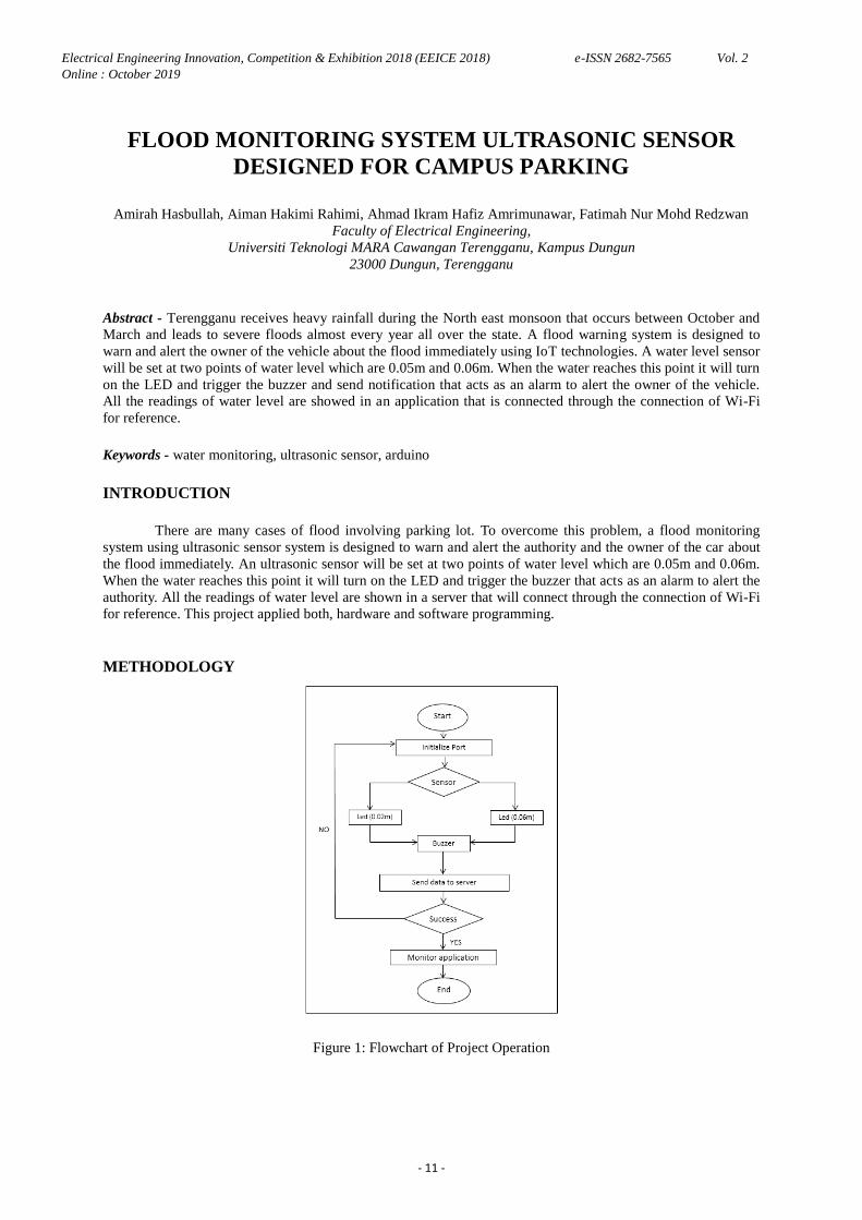
There are many cases of flood involving parking lot. To overcome this problem, a flood monitoring
system using ultrasonic sensor system is designed to warn and alert the authority and the owner of the car about
the flood immediately. An ultrasonic sensor will be set at two points of water level which are 0.05m and 0.06m.
When the water reaches this point it will turn on the LED and trigger the buzzer that acts as an alarm to alert the
authority. All the readings of water level are shown in a server that will connect through the connection of Wi-Fi
for reference. This project applied both, hardware and software programming.
METHODOLOGY
Figure 1: Flowchart of Project Operation
Electrical Engineering Innovation, Competition & Exhibition 2018 (EEICE 2018) e-ISSN 2682-7565 Vol. 2
Online : October 2019
- 12 -
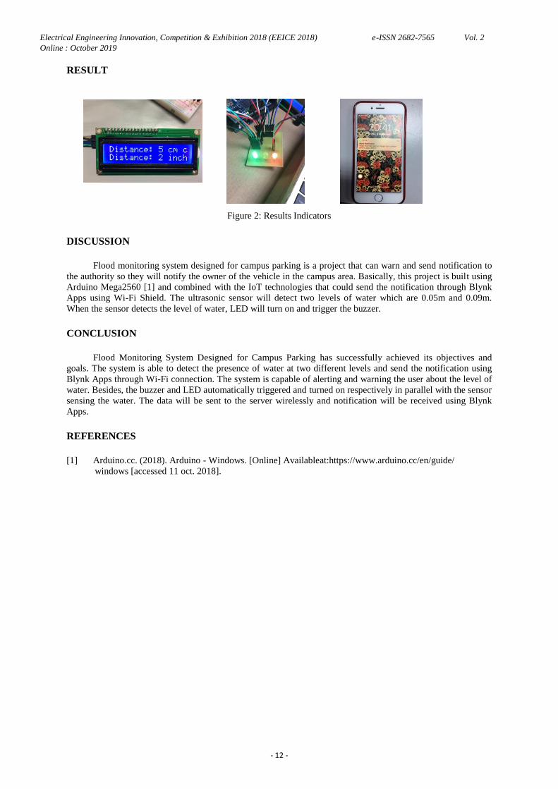
RESULT
Figure 2: Results Indicators
DISCUSSION
Flood monitoring system designed for campus parking is a project that can warn and send notification to
the authority so they will notify the owner of the vehicle in the campus area. Basically, this project is built using
Arduino Mega2560 [1] and combined with the IoT technologies that could send the notification through Blynk
Apps using Wi-Fi Shield. The ultrasonic sensor will detect two levels of water which are 0.05m and 0.09m.
When the sensor detects the level of water, LED will turn on and trigger the buzzer.
CONCLUSION
Flood Monitoring System Designed for Campus Parking has successfully achieved its objectives and
goals. The system is able to detect the presence of water at two different levels and send the notification using
Blynk Apps through Wi-Fi connection. The system is capable of alerting and warning the user about the level of
water. Besides, the buzzer and LED automatically triggered and turned on respectively in parallel with the sensor
sensing the water. The data will be sent to the server wirelessly and notification will be received using Blynk
Apps.
REFERENCES
[1] Arduino.cc. (2018). Arduino - Windows. [Online] Availableat:https://www.arduino.cc/en/guide/
windows [accessed 11 oct. 2018].
Electrical Engineering Innovation, Competition & Exhibition 2018 (EEICE 2018) e-ISSN 2682-7565 Vol. 2
Online : October 2019
- 13 -
IOT BASED TIMER ALARM SYSTEM
Muhammad Amirul Hafidz Mohd Nazri, Muhammad Asyraf Azim Amran, Asyraf Ahmad Safri,
Fadzli Dzulhilmi Mohd Fauzi
Faculty of Electrical Engineering,
Universiti Teknologi MARA, Cawangan Terengganu, Kampus Dungun
23000 Dungun, Terengganu
[email protected], [email protected], [email protected]
Abstract - Nowadays, some students face problems to wake up in the morning and miss deadlines for
assignments. This results to absence in classes, meetings, exams and late submission of assignments. The aim of
this project is to develop a timer that can force the user to wake up from their sleep, and issue reminder of the
deadline of their assignments. The method used in this application is to let the user sets the timer using their
phones via internet connection and the timer alarm will produce a disturbing sound and switch on the lamp. The
hardware part of the IoT based Timer Alarm System is Arduino UNO. Arduino UNO will be connected to the
internet by using a Wi-Fi module which is ESP8266 and the timer can be set by using an application called
Blynk. It can be programmed using the Arduino IDE software and requires a USB-to-serial converter to load the
program to Arduino UNO which is the main component of the IoT based Timer Alarm System. IoT based Timer
Alarm System also requires relay that acts as a switch to control the output of the lamp and the motor.
Keywords - Internet of Things, timer alarm, Arduino UNO, Blynk
INTRODUCTION
There are many problems of students waking up late which lead to the absence of classes, meetings and
exams. To overcome this problem, an IoT Based Timer Alarm System [1-3] is designed to wake up and alert the
students with the capability of producing an annoying sound, turning off the fan and switching on the lamp. The
user will set the timer via Blynk apps [4,5] through their phones that requires an internet connection. The relay
will trigger on the set time and then the alarm will produce an annoying sound, turn off the fan and switch on the
lamp. The user will wake up and turn off the alarm. This project applied both, hardware and software
programming.
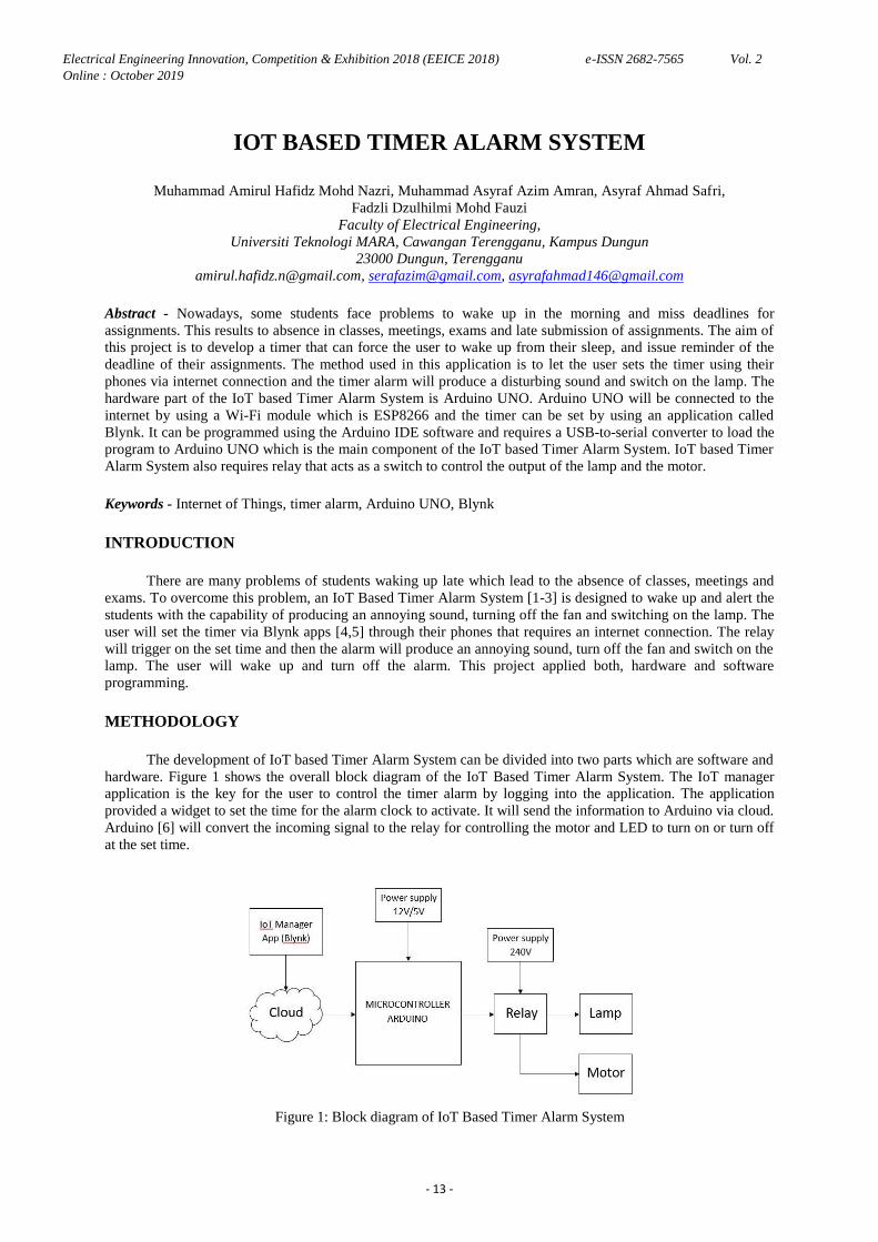
METHODOLOGY
The development of IoT based Timer Alarm System can be divided into two parts which are software and
hardware. Figure 1 shows the overall block diagram of the IoT Based Timer Alarm System. The IoT manager
application is the key for the user to control the timer alarm by logging into the application. The application
provided a widget to set the time for the alarm clock to activate. It will send the information to Arduino via cloud.
Arduino [6] will convert the incoming signal to the relay for controlling the motor and LED to turn on or turn off
at the set time.
Figure 1: Block diagram of IoT Based Timer Alarm System
Electrical Engineering Innovation, Competition & Exhibition 2018 (EEICE 2018) e-ISSN 2682-7565 Vol. 2
Online : October 2019
- 14 -
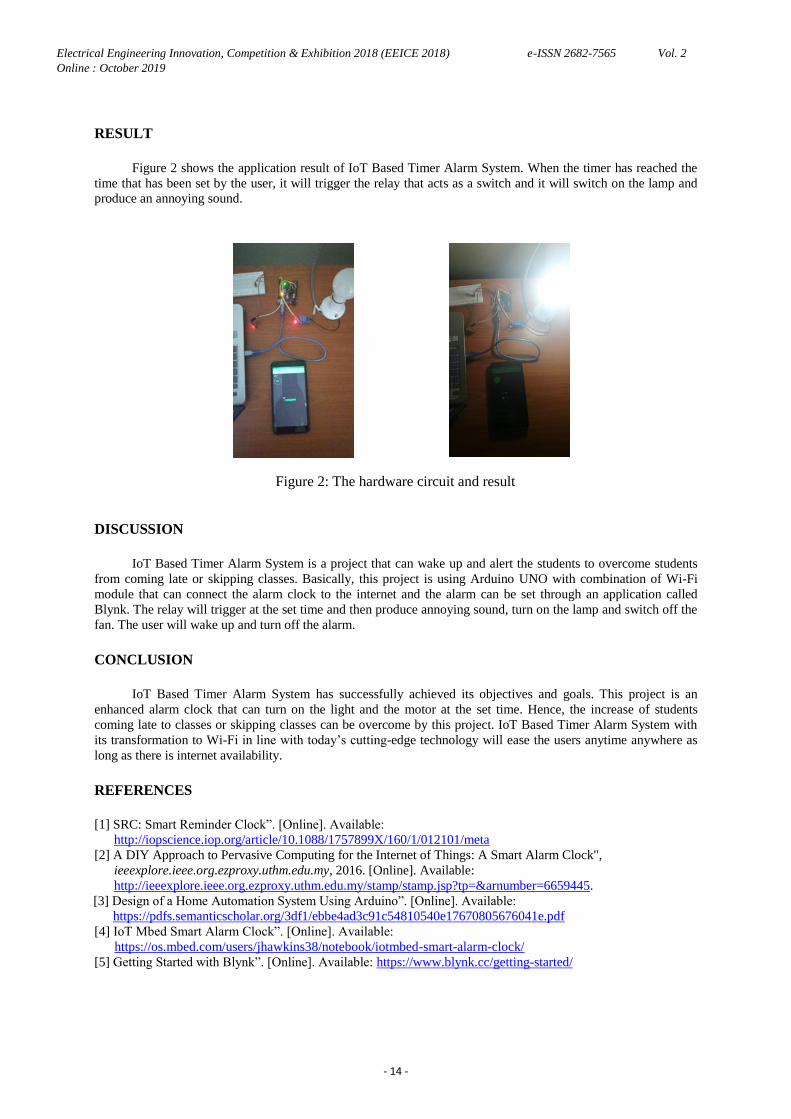
RESULT
Figure 2 shows the application result of IoT Based Timer Alarm System. When the timer has reached the
time that has been set by the user, it will trigger the relay that acts as a switch and it will switch on the lamp and
produce an annoying sound.
Figure 2: The hardware circuit and result
DISCUSSION
IoT Based Timer Alarm System is a project that can wake up and alert the students to overcome students
from coming late or skipping classes. Basically, this project is using Arduino UNO with combination of Wi-Fi
module that can connect the alarm clock to the internet and the alarm can be set through an application called
Blynk. The relay will trigger at the set time and then produce annoying sound, turn on the lamp and switch off the
fan. The user will wake up and turn off the alarm.
CONCLUSION
IoT Based Timer Alarm System has successfully achieved its objectives and goals. This project is an
enhanced alarm clock that can turn on the light and the motor at the set time. Hence, the increase of students
coming late to classes or skipping classes can be overcome by this project. IoT Based Timer Alarm System with
its transformation to Wi-Fi in line with today‟s cutting-edge technology will ease the users anytime anywhere as
long as there is internet availability.
REFERENCES
[1] SRC: Smart Reminder Clock”. [Online]. Available:
http://iopscience.iop.org/article/10.1088/1757899X/160/1/012101/meta
[2] A DIY Approach to Pervasive Computing for the Internet of Things: A Smart Alarm Clock",
ieeexplore.ieee.org.ezproxy.uthm.edu.my, 2016. [Online]. Available:
http://ieeexplore.ieee.org.ezproxy.uthm.edu.my/stamp/stamp.jsp?tp=&arnumber=6659445.
[3] Design of a Home Automation System Using Arduino”. [Online]. Available:
https://pdfs.semanticscholar.org/3df1/ebbe4ad3c91c54810540e17670805676041e.pdf
[4] IoT Mbed Smart Alarm Clock”. [Online]. Available:
https://os.mbed.com/users/jhawkins38/notebook/iotmbed-smart-alarm-clock/ [5] Getting Started with Blynk”. [Online]. Available: https://www.blynk.cc/getting-started/
Electrical Engineering Innovation, Competition & Exhibition 2018 (EEICE 2018) e-ISSN 2682-7565 Vol. 2
Online : October 2019
- 15 -
AUTOMATIC SOCKET
Muhammad Razin Aiman Rizal, Muhammad Zahran Zaidi, Muhammad Nurhazim Abdul Khalil,
Mohamad Yusof Mat Zain
Faculty of Electrical Engineering,
Universiti Teknologi MARA, Cawangan Terengganu, Kampus Dungun
23000 Dungun, Terengganu
[email protected], [email protected], [email protected],
Abstract - This project is developed to ensure the safety of people that use electrical appliances such as iron and
hair dryer. It will help the users to turn on and off the appliances automatically. The current will be cut off when
there is no one or no motion around the electrical appliances which are connected to the proposed socket. Each
has their own function in the circuit. Transformer that being used is step down transformer which means it will
reduce the amount of voltage that enters the circuit. For relay it will act as switch while the rectifier will change
the current from AC to DC. Capacitor is to straighten the DC signal wave. In the circuit, voltage regulator
provides a stable DC voltage. LED in this circuit is fairly simple because it will only emit light. The most
important component in this circuit is PIR sensor as it will detect motion around its radius. Without it, the project
is nothing. Lastly for NPN transistor, current that enters through base will be amplified to produce a large
collector and emitter current. Hopefully this project will bring positive outcome to students and anyone that uses
it.
INTRODUCTION
Automatic socket is a project that uses PIR sensor [1, 2] at the socket and it will be the main component
for this project [3]. Motion sensor is used to use cut off current and it is the main component in this project. The
usage of motion sensor to cut off or reducing the current can be seldom found so that‟s why we use it. The main
process in this whole project is not complicated at all. It‟s not too easy and at the same time it‟s not too hard to
do. Programming is not needed in this project at all because the flow of the circuit is simple. The components
used in this project are affordable.
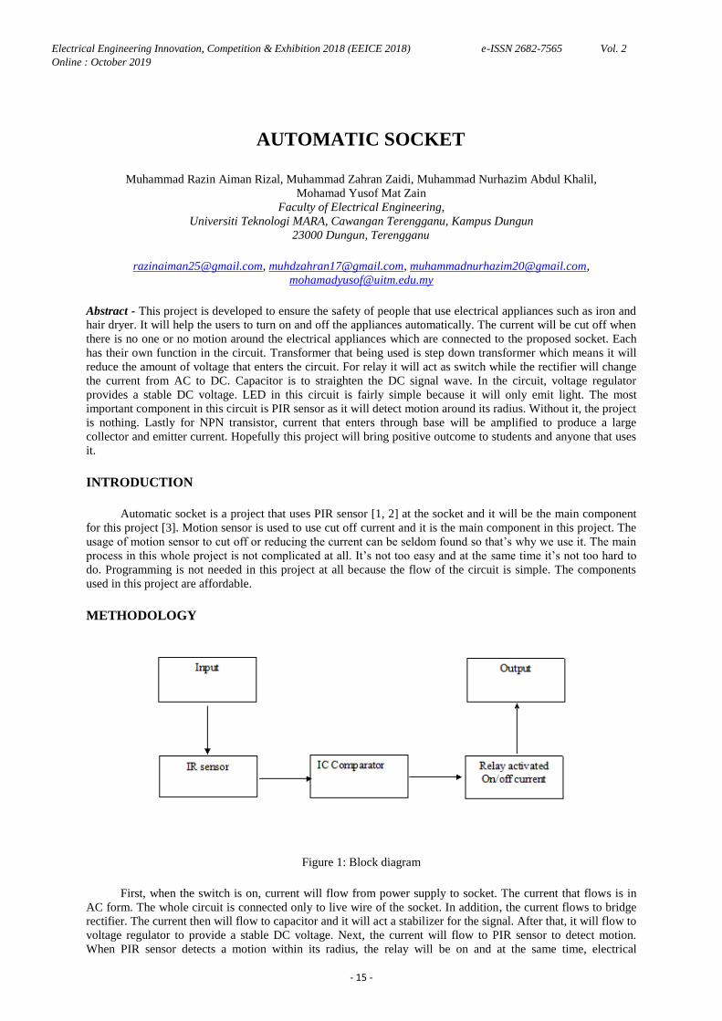
METHODOLOGY
Figure 1: Block diagram
First, when the switch is on, current will flow from power supply to socket. The current that flows is in
AC form. The whole circuit is connected only to live wire of the socket. In addition, the current flows to bridge
rectifier. The current then will flow to capacitor and it will act a stabilizer for the signal. After that, it will flow to
voltage regulator to provide a stable DC voltage. Next, the current will flow to PIR sensor to detect motion.
When PIR sensor detects a motion within its radius, the relay will be on and at the same time, electrical
Electrical Engineering Innovation, Competition & Exhibition 2018 (EEICE 2018) e-ISSN 2682-7565 Vol. 2
Online : October 2019
- 16 -
appliances will also be turned on. The circuit will then turn on. If PIR does not detect the motion, it loops back to
the circuit. If PIRs detect the motion, it will activate the socket and the appliances will turn on.
RESULT AND DISCUSSION
The purpose of the circuit is to determine the voltage value at leg 2 and leg 3 of IC Comparator. It is to
find which leg has the highest value. We use LED as our indicator. When LED doesn't light up, the voltage at leg
2 is higher than 3 but when the LED doesn‟t light up, the voltage at leg 3 is higher than leg 2. When we first run
the simulation, we didn't get a static voltage around the circuit because we didn't set a anything at transformer.
Even after we set some value into transformer, we still couldn't get a static voltage around the circuit. Not only
that, the voltage in the circuit is very small. Only then, we get a static voltage around the circuit.
CONCLUSION
The process of developing this project has its own up and down. Since we encounter the problem from
the simulation in Proteus, it is really hard to create the prototype based on the simulation. If the prototype is
working out smoothly, it should function the way it is. The function of the circuit is to cut the current when there
is no motion detected around the sensor.
REFERENCE
[1] Passive Infrared (PIR) Sensor Based Security System. International Journal of Electrical, Electronics and
Computer Systems.(Chandra Nepal, Gopal & Biswa, Rajen & Maya Adhikari, Devi & Chodon, Pema &
Gyeltshen, Sangay & , Chencho).( 14. Page 772-778). (2013).
[2] Automatic Lighting and Security System Design Using PIR Motion Sensor. Journal of Information
Technology,
Jahangirnagar university.(Puspita Mouri, Syeda & Sakib, Syed & Ferdous, Zannatul & Abu Taher, Md). ( 4.
Page 15-18). (2016).
[3] Smart Socket for Activity Monitoring. (sneps-sneppe, Manfred & Namiot, Dmitry). (2015).
Electrical Engineering Innovation, Competition & Exhibition 2018 (EEICE 2018) e-ISSN 2682-7565 Vol. 2
Online : October 2019
- 17 -
TRASH CAN MONITORING USING IOT
Mohammad Aiman Lakim, Muhammad Afiq Ad Wahab Rakhdi, Nur Amirah Mohd Radi,
Fadzli Dzulhilmi Mohd Fauzi
Faculty of Electrical Engineering,
Universiti Teknologi MARA, Cawangan Terengganu, Kampus Dungun
23000 Dungun, Terengganu
[email protected], [email protected], [email protected]
Abstract - This project is about monitoring Trash Can using Internet of Things (IoT). The purpose of this project
is to make sure the trash can is not overload and manageable at the walkway and also the trash management will
be more systematic. Besides, the project will build a system which will notify the management to clean the trash
can immediately. The main part of the system is Espresso Lite V2 known for the Wi-Fi development board
micro-controller. In this system, Ultrasonic sensor is used as a sensor and placed inside the trash can to measure
the garbage level. When the garbage reaches its maximum level, a notification will be sent by the Blynk
application to the user which is the college‟s management as a notification so the employees need to take further
actions to empty the bin. This system will help in having a clean campus environment in a better way. By using
this system the management does not have to clean the trash can constantly however Blynk application will
notify if the sensor detects the filled garbage has reached its specific level. In addition, a camera is used to
monitor the condition of the trash can. This project not just helps the employees but also eases and improves the
cleaning management.
Keywords - Internet of Thing, Espresso Lite V2, Ultrasonic Sensor, Blynk, Monitoring Camera
INTRODUCTION
Nowadays certain actions are taken to improve the level of cleanliness in the campus. Students are
getting active by doing all possible things to clean their surroundings. Various movements are also started by the
University to increase cleanliness. The trash can monitoring using internet of things (IoT) [1-3] should be
applied at the college. By applying this project, The Trash Can could be monitored from being overload. This
project will also notify the management when the dustbin is full .The management will notify the employee staff
to take further action about this problem. This project also helps staff to be more alert about the cleanliness at the
college.
One of the main components of this project is Espresso Lite V2 as the main controller to run this project.
Espresso will act as microcontroller to collect data, process and prepare to transmit to the cloud (internet) [4].
This project also uses Bylnk app that provides link address to connect with the cloud (internet). The college‟s
management can live stream the trash can from their computer or any gadget that is connected to the internet,
and then the management can notify the staff by turning ON the LED as alarm to alert the employees.
The objectives of this project:
i) To make sure the trash can is not overload. The college‟s management can monitor the Trash Can
from their office.
ii) To notify the management when dustbin is full. The college‟s management can take further action
to solve this problem.
iii) IoT help the cleaner staffs to be more alert about the cleanliness at the college
METHODOLOGY
This project starts with the measurement of the sensor, if the level of the trash in the trash can is not full
thus, the operation will be delayed until the trash level reaches full. After the trash is full the sensor will send
notification which is connected to internet through BLYNK application to the management. Besides, the
management can recheck the trash level by live streaming monitoring camera to do confirmation either the trash
can is full by garbage or other things such as animal inside it. İf it just an alarm for the animals so the operation
flow is delayed, however if it is really full of the garbage then the management needs to turn on the LED button
Electrical Engineering Innovation, Competition & Exhibition 2018 (EEICE 2018) e-ISSN 2682-7565 Vol. 2
Online : October 2019
- 18 -
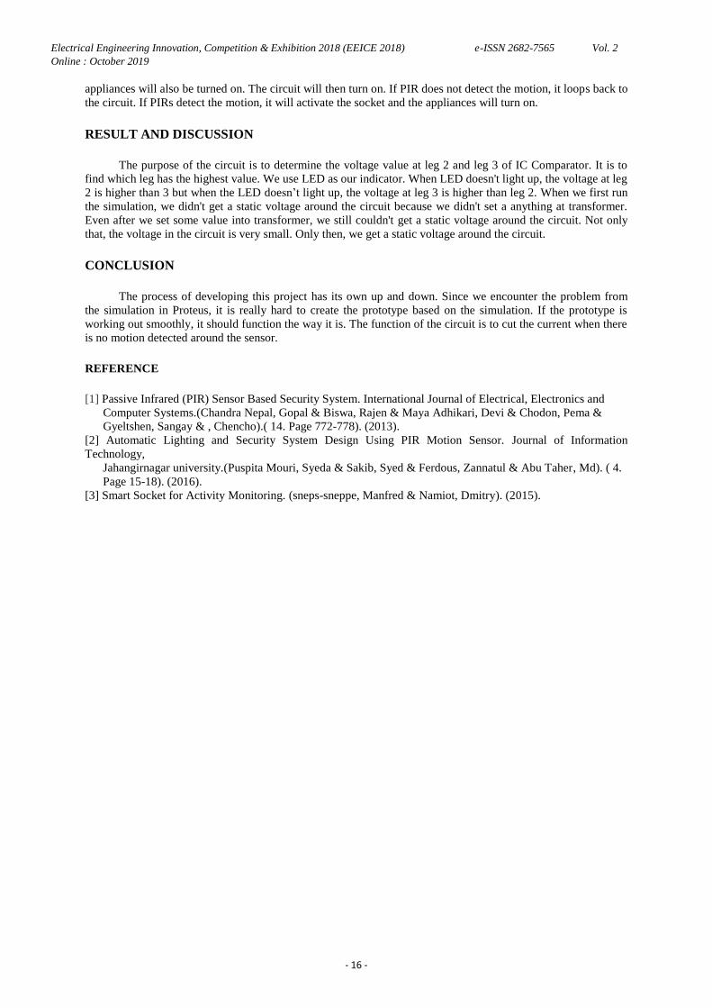
via phone on the BLYNK application which is as an indicator to the employees to clean that trash can
immediately.
Figure 2: PCB layout of this project.
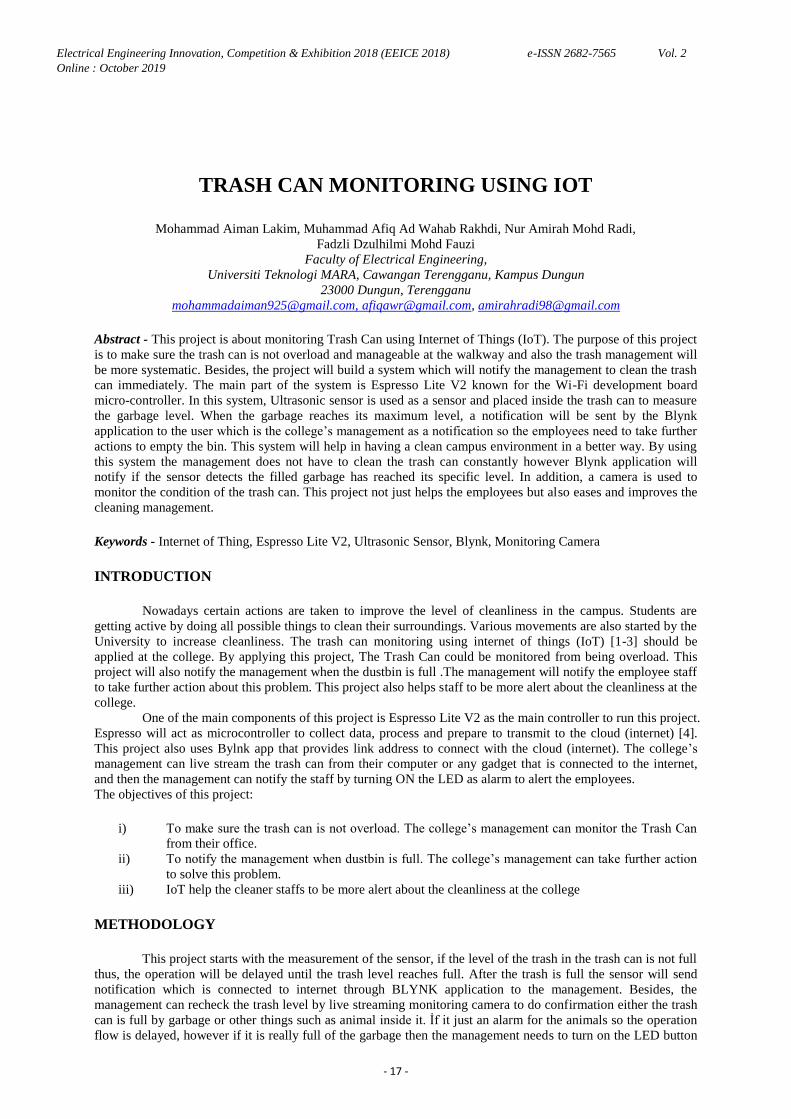
RESULT AND DICUSSION
Based on the analysis result from this project, if the trash can is full, ultrasonic sensor will detect the
height of garbage and notify through Blynk application. Then, college management will check whether the trash
is really full or not by monitoring camera device. Next, when the trash can really is full, the college management
will notify the staff by turning “ON” the LED on Blynk application as an indicator. Figure 3 shows the used
prototype for presentation progress.
Figure 3. Prototype
CONCLUSIONS
To summarize, this project can help in decreasing the amount of garbage at the college because
whenever the dustbin is full, notification will be sent to the head of staff management. Head of management will
monitor the condition of dustbin using phone and will turn on LED at dustbin to notify his staff to take further
action to clean the dustbin. So that, the dustbin will always in a clean state. This project is also easy to handle by
the use of IoT, as the internet is one of the today‟s hot topics. Blynk application connects and controls the project.
After all, the movement of this project can ease both collage management and their employees as the trash can is
available to be monitored by camera monitoring device. Therefore, employees do not have to go to the college to
check the dustbin often.
REFERENCES
[1] Prof. Dr. Sandeep M. Chaware, Shriram Dighe, Akshay Joshi, Namrata Bajare, Rohini Korke. “Smart
Garbage Monitoring System using Internet of Things (IOT)”. Innovative Research in Electrical, Electronics,
Instrumentation and Control Engineering[Online]. Vol. 5, Issue 1, (2017, January).
[2] Norfadzlia Mohd Yusof, Aiman Zakwan Jidin , and Muhammad Izzat Rahim. “Smart Garbage Monitoring
System for Waste Management”. MATEC Web of Conferences 97, 01098, 2017.
[3] Anitha A. “Garbage Monitoring System Using IoT”. School of Information Technology and Engineering,
VIT
University, Vellore632014, Tamil Nadu, India. IOP Conf. Series: Materials Science and Engineering 263
042027. (2017)
Electrical Engineering Innovation, Competition & Exhibition 2018 (EEICE 2018) e-ISSN 2682-7565 Vol. 2
Online : October 2019
- 19 -
[4] ESPresso Lite V2. (2016). Introduction to espresso lite V2 [Online]. Available: http://www.espressolite.com/.
IOT CONTROLLED WATER SYSTEM USING PIR MOTION
SENSOR AND VOICE ACTIVATION
Muhammad Aza Azree Shariff Abdul Aziz, Dzaki Dziauddin Sabaruddin, Kartini binti Mohammad,
Wan Ahmad Khusairi Wan Chek
Faculty of Electrical Engineering,
Universiti Teknologi MARA Cawangan Terengganu, Kampus Dungun
23000 Dungun, Terengganu
[email protected], [email protected], [email protected], [email protected]
Abstract - Humans need water to perform daily activities such as bathing and drinking. According to study,
much water wastage occurs during bathing. Most consumers do not turn off the water while using soap and
shampoo. And there are some users who forget to turn off the water at hostel or flats. This project proposes a
smart shower that can be controlled using the Internet of Things (IoT). The IoT controlled shower system uses
PIR motion sensor and voice activation which aims to change people behavior in water usage by controlling the
water flow. This project uses a PIR motion sensor and voice as the input. This input is sent to NodeMCU
microcontroller and the microcontroller then turns on the water pump based on the voice and presence detected.
Google Assistant is chosen since it has the ability to perform two-way interaction with human. NodeMCU
microcontroller is selected for this project since the price is more affordable compared to other WIFI connected
microcontroller.
Keywords - smart shower, Internet of Things (IoT), PIR motion sensor, NodeMCU microcontroller, Google
Assistant, WIFI
INTRODUCTION
Water is a basic necessity for human. Humans use water for drinking, bathing and watering trees. People
waste a large volume of water while taking shower every day. On average, people waste 7 gallons of water per
minute. So, for a shower session of 10 minutes means 70 gallons of water is wasted [1]. The IoT controlled shower
system uses PIR and voice activation which aims to change student‟s behavior in water usage by controlling the
water flow. This project uses PIR and voice as the input. This input is sent to NodeMCU microcontroller and the
microcontroller then turns on the pump based on the voice and presence detected. Google Assistant is chosen since
it has the ability to interact with human [2]. NodeMCU microcontroller is selected for this project since it is
applicable to be connected to the internet [3]. The advantage of this project is to reduce the wastage of water
among the public especially in crowded places such as a hostel. With this project, water is no longer wasted and the
water bill can also be reduced.
METHODOLOGY
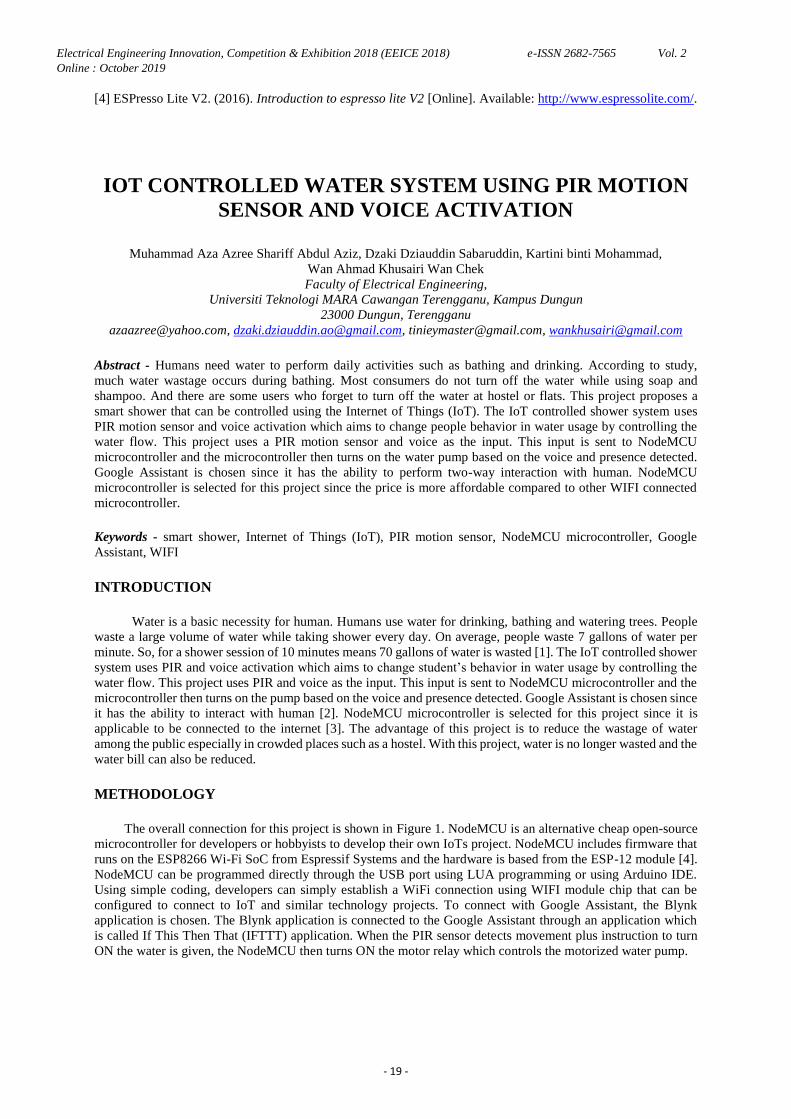
The overall connection for this project is shown in Figure 1. NodeMCU is an alternative cheap open-source
microcontroller for developers or hobbyists to develop their own IoTs project. NodeMCU includes firmware that
runs on the ESP8266 Wi-Fi SoC from Espressif Systems and the hardware is based from the ESP-12 module [4].
NodeMCU can be programmed directly through the USB port using LUA programming or using Arduino IDE.
Using simple coding, developers can simply establish a WiFi connection using WIFI module chip that can be
configured to connect to IoT and similar technology projects. To connect with Google Assistant, the Blynk
application is chosen. The Blynk application is connected to the Google Assistant through an application which
is called If This Then That (IFTTT) application. When the PIR sensor detects movement plus instruction to turn
ON the water is given, the NodeMCU then turns ON the motor relay which controls the motorized water pump.
Electrical Engineering Innovation, Competition & Exhibition 2018 (EEICE 2018) e-ISSN 2682-7565 Vol. 2
Online : October 2019
- 20 -
Fig 1: Overall project connection
RESULT AND DISCUSSION
Table 1 shows the result of the project. Based on the result, the motor will turn ON if both two inputs are
ON. If either one of the inputs is in OFF condition, the motor will not be turned ON thus water would not flow out.
Table 1: Result
INPUT OUTPUT
PIR SENSOR VOICE MOTOR
OFF OFF OFF
OFF ON OFF
ON OFF OFF
ON ON ON
CONCLUSION
This project will be able to provide a more good facility to the users in campus and also aim to make
UiTM Dungun one the smart campuses in Malaysia. Saving water also has become a necessity since Malaysia is
exposed to the El Nino effect, which reduces the amount of rainfall in the dry season [5]. By developing this
project, hopefully it can help to save the usage of water usage so it can help the university to reduce the water
bill payment. Furthermore, new knowledge is gained about the latest technology regarding IoT such as the
Google Assistant, IFTTT and Blynk application, and also the types of microcontroller that can be used to
perform the IoT operation.
REFERENCES
[1] Constellation Residential and Small Business Blog. (2018). How much water do you use in a shower?
Constellation. [online] Available at
https://blog.constellation.com/2016/07/05/average-shower-length-flowchart/ [Accessed 26 Jun. 2019].
[2] Msn.com. (2018). Google Assistant sounds so human because Google made up a super-specific backstory
for it. [online] Available at:
https://www.msn.com/en-us/news/technology/google-assistant-sounds-so-human-because-google-made-up-
a-super-specific-backstory-for-it/ar-BBOdPfW [Accessed 26 Jun. 2019].
[3] IBM Developer. (2019). Getting to know NodeMCU and its DEVKIT board. [online] Available at:
https://developer.ibm.com/tutorials/iot-nodemcu-open-why-use/ [Accessed 26 Jun. 2019].
[4] EspressifWikiDevi",Wikidevi.com,2019. [Online]. Available: https://wikidevi.com/wiki/Espressif.
[Accessed: 26- Jun- 2019].
[5] Keeping the taps flowing - Why Not,| The Star Online",Thestar.com.my, 2019. [Online]. Available:
https://www.thestar.com.my/opinion/columnists/why-not-wsw/2010/03/12/keeping-the-taps flowing/.
[Accessed: 26- Jun- 2019
Electrical Engineering Innovation, Competition & Exhibition 2018 (EEICE 2018) e-ISSN 2682-7565 Vol. 2
Online : October 2019
- 21 -
AUTOMATIC PLANT WATERING AND FERTILIZING
SYSTEM
Muhammad Fauzan Faridz, Muhammad.Fareez Mohd Ainul Hakeem, Muhammad Firdaus Umar,
Najwa Nasuha Binti Mahzan, Haslizamri Bin Md Shariff
Faculty of Electrical Engineering,
Universiti Teknologi MARA Cawangan Terengganu, Kampus Dungun
23000 Dungun, Terengganu
[email protected], [email protected], [email protected], [email protected]
Abstract - IoT or internet of things is an advanced technology that allows user to control hardware devices through
the Internet which is very fast and cover a wide coverage area. In this work, IoT is used to control the amount of
water that the plant needs through the controller which is Arduino Uno board via mobile phone. This project will
remotely water the plant through internet which can make user‟s daily life easier than before. Furthermore,
Arduino Uno is required in this project as the controller board and moisture sensor to detect the moisture of the soil
whether it has received enough water or not. Besides, fertilizing system will be activated once the time duration is
triggered. The time duration can be set by user at any time they want to do fertilizing. In a nutshell, this project can
save a lot of user energy, money and time as well can be totally utilized by the users.
Keywords - IoT, Arduino UNO, Moisture sensor, Watering and Fertilizing, Smart Gardening
INTRODUCTION
In this century, people are eagerly catching up with the evolvement of technology which happens rapidly.
With the latest technology, all their daily lives and works have been upgraded into something more useful and
technology wise. Internet of things (IoT) is used in this project. IoT is the internetworking of physical devices,
vehicles, buildings, and other items that enable these projects to collect or exchange data [1]. IoT allows object to
be sensed and controlled remotely across existing network infrastructure, creating opportunities for more direct
integration of physical world into computer-based systems and resulting in improved efficiency, accuracy and
economic benefits.
In terms of smart campus, IoT has been implemented widely in the entire world especially in United States
[2]. There are plenty of applications that can be operated by using IoT in a campus such as smart hostel [3], smart
room [4] and many more. For this specific project, environment theme is chosen where the main focus is to nurture
the environment wirelessly and unattended. An automatic plant watering system is used to water the plants in the
campus with the right amount of water so that the plants will not wilt. The system also provides fertilizing system
so that the plants can be fertilized accordingly as scheduled. This project is introduced to make it easier for the user
to save energy in watering and fertilizing the plant. Not only that, by having this proposed project, users are able to
reduce money (in terms of hiring more workers to look after the plants) and control water sources wastage. The
objectives of this project are to provide prompt notification on conditions of the plants in the campus. Next is to
reduce time consumption for users to monitor all the plants in the campus and to design an automatic plant
watering and fertilizing system in the campus without being attended.
METHODOLOGY
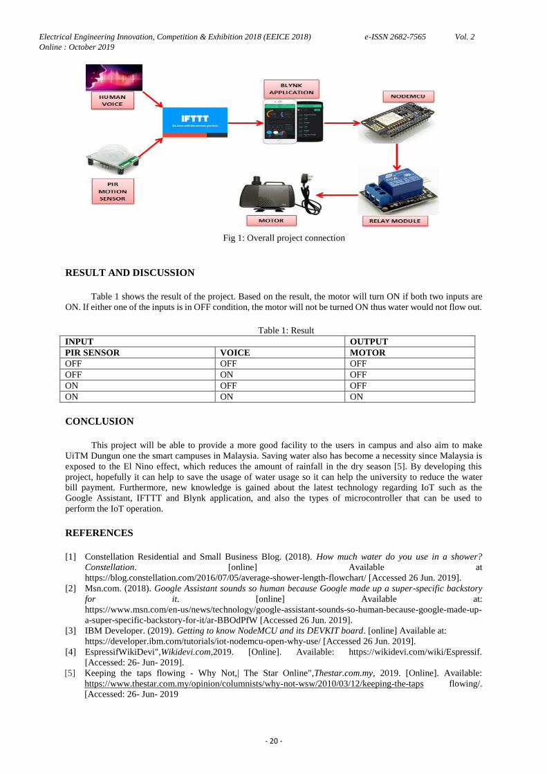
Firstly, Moisture sensor is placed at the soil of the plant to sense whether the soil is dry or wet. Whenever
the soil is dry, the watering pump will turn on until the soil is wet. The fertilizing system will be delayed for twice
per month. Every 2 weeks the fertilizing pump will turn on.
Electrical Engineering Innovation, Competition & Exhibition 2018 (EEICE 2018) e-ISSN 2682-7565 Vol. 2
Online : October 2019
- 22 -
Figure 2. Flowchart of the proposed project
RESULT AND DICUSSION
As shown in Table 1, the moisture sensor is recorded using digital reading meaning in which the output will show only 0 or 1. If the moisture reading on the Blynk apps is high, the soil is dry and will send notification to user
to water the plant. If the moisture reading is low, it means that the soil is wet and the user does not need to water the
plant.
Table 1. Dryness of the soil
Soil moisture Moisture reading on Blynk
apps
Dry High
Wet Low
CONCLUSIONS
In a nutshell, Gardeners can save their energy which they can do the watering and fertilizing operation
wirelessly, check the soil moisture promptly so that they can take quick action on that matter, and they also can
save money and time if the proposed system operates well. For future purposes, this watering and fertilizing
system can be developed using other type of microcontroller such as Wio Link. By using this microcontroller, it is
easier because this microcontroller does not require any codes and simple circuit connection.
REFERENCES
[1] “Internet of things,” Wikipedia, 06-May-2018. [Online]. Available: https://en.wikipedia.org/wiki/Internet_of_things. [Accessed: 09-May-2018]. [2] D. Raths08/24/17, “'Smart' Campuses Invest in the Internet of Things,” Campus Technology, 24-Aug-2017.
[Online]. Available: https://campustechnology.com/articles/2017/08/24/smart-campuses-invest-in-the- internet-of-things.aspx. [Accessed: 09-May-2018].
[3] D. T. K. Singhal, “IOT Enabled Smart Hostel: A Futuristic Perpective,” International Journal for Research in Applied Science and Engineering Technology, vol. V, no. IX, pp. 1451–1466, 2017. [4] “Light and room control and the Internet of Things (IoT): an expert look,” i-SCOOP. [Online]. Available:
https://www.i-scoop.eu/internet-of-things-guide/light-room-control-iot/. [Accessed: 09-May-2018].
Electrical Engineering Innovation, Competition & Exhibition 2018 (EEICE 2018) e-ISSN 2682-7565 Vol. 2
Online : October 2019
- 23 -
WI-FI CONTROLLED SMART SWITCH USING
SMARTPHONE
Nurul Huda Ruslan, Nurul Nadia Mokhtar, Siti Fadhilah Ibrahim, Rina Abdullah
Faculty of Electrical Engineering
Universiti Teknologi MARA, Cawangan Terengganu, Kampus Dungun,
23000 Sura Hujung Dungun, Terengganu
[email protected] , [email protected]
Abstract - Internet of Things technology is the future of residential related technology which is designed to
deliver and distribute number of services inside and outside the house via networked devices in which all the
different applications & the intelligence behind them are integrated and interconnected so this Wi-Fi Controlled
Smart Switch by using Smartphone is created. Students‟ rooms could be the most dangerous place for the
students themselves. We usually have problem dealing with electrocutions which are also known as
overconsumption of energy that lead to more dangerous situations. This situation occurred because students
always leave their room‟s lamp or fan even no one is using it. They also forgot to turn off the lamp or fan.
Because of this, smart switch is designed to avoid this situation to happen more in the future. This project
stresses on turning lamp on or off automatically by using smartphone. This project is made with having Wi-Fi
module as its output, Arduino UNO for data interpretation and a load which is bulb as output. It is completely
controlled over by the user all remotely by using „Blynk‟ application on smartphone via Wi-Fi to turn on or off
the bulb. This Wi-Fi Controlled Smart Switch could lead student life towards perfection and far from danger.
Keywords - Smart Switch, Arduino UNO, ESP8266 module, Smartphone application, Blynk
INTRODUCTION
The concept of “automated home/smart home” was first introduced over 80 years ago, and has been
facing different technical limitations since then. Recently, service providers and home appliance manufacturers
have launched a new initiative to bring the concept of smart homes to reality [1-3]. Since home energy
accounts for approximately one-third of total energy consumption [4], a home appliance, which in our case is
students‟ room appliances become a critical focus to improve energy efficiency. To solve this problem, this
paper proposes a Wi-Fi controlled smart switch by using smartphone. In this globalization era, smartphone is the
most important technology that does the communication meanwhile contains a lot of functions like browsing
internet, media player, GPS (Global Positioning System) locator and others [5]. Nowadays, there are a lot home
automation systems with the same operating system which are to automatically turn on or off electrical
appliances. However, most of the smart switch that had been designed is limited in distances to use it. So our
smart socket uses Wireless system and internet as wireless data transmission so that the user will have the ability
to control their electrical appliances from anywhere. Internet is widely used these days because it is convenient
and cost friendly.
METHODOLOGY
This project presents the design, construction, development and control the load (lamp) that applies to the
Smart Switch using smartphone. This idea is based on the problem that happens especially in campus. The block
diagram of the system is shown in Figure 1. The integrated system of Wi-Fi Controlled Smart Switch using
smartphone consists of a Wi-Fi module for input, the Atmega 328p microcontroller for data interpretation and 2
loads (fan and bulb) as the output. The Wi-Fi module is based on the ESP8266 serial module and it will control
the relay working status through the application in Smartphones. The microcontroller uses the information
provided by the sensor to control the bulbs, and to cut off the power supply.
Electrical Engineering Innovation, Competition & Exhibition 2018 (EEICE 2018) e-ISSN 2682-7565 Vol. 2
Online : October 2019
- 24 -
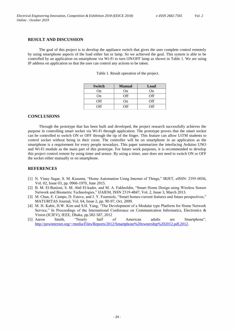
RESULT AND DISCUSSION
The goal of this project is to develop the appliance switch that gives the user complete control remotely
by using smartphone aspects of the load either fan or lamp. So we achieved the goal. This system is able to be
controlled by an application on smartphone via Wi-Fi to turn ON/OFF lamp as shown in Table 1. We are using
IP address on application so that the user can control any actions to be taken.
Table 1. Result operation of the project.
CONCLUSIONS
Through the prototype that has been built and developed, the project research successfully achieves the
purpose in controlling smart socket via Wi-Fi through application. The prototype proves that the smart socket
can be controlled to switch ON or OFF through the tip of the finger. This feature can allow UiTM students to
control socket without being in their room. The controller will be on smartphone in an application as the
smartphone is a requirement for every people nowadays. This paper summarizes the interfacing Arduino UNO
and Wi-Fi module as the main part of this prototype. For future work purposes, it is recommended to develop
this project control remote by using timer and sensor. By using a timer, user does not need to switch ON or OFF
the socket either manually or on smartphone.
REFERENCES
[1] N. Vinay Sagar, S. M. Kusuma, “Home Automation Using Internet of Things,” IRJET, eISSN: 2395-0056,
Vol. 02, Issue 03, pp. 0966-1970, June 2015.
[2] B. M. El-Basioni, S. M. Abd El-kader, and M. A. Fakhreldin, “Smart Home Design using Wireless Sensor
Network and Biometric Technologies,” IJAIEM, ISSN 2319-4847, Vol. 2, Issue 3, March 2013.
[3] M. Chan, E. Campo, D. Esteve, and J. Y. Fourniols, “Smart homes-current features and future perspectives,”
MATURITAS Journal, Vol. 64, Issue 2, pp. 90-97, Oct. 2009.
[4] M. H. Kabir, H.W. Kim and S.H. Yang, “The Development of a Modular type Platform for Home Network
Service,” In Proceedings of the International Conference on Communication Informatics, Electronics &
Vision (ICIEV), IEEE, Dhaka, pp.582-587, 2012
[5] Aaron Smith, “Nearly half of American adults are Smartphone”,
http://pewinternet.org/~/media/Files/Reports/2012/Smartphone%20ownership%202012.pdf,2012.
Switch Manual Load
On On On
On Off Off
Off On Off
Off Off Off
Electrical Engineering Innovation, Competition & Exhibition 2018 (EEICE 2018) e-ISSN 2682-7565 Vol. 2
Online : October 2019
- 25 -
AN ARDUINO BASED AUTOMATIC SHOWER SENSOR
DESIGN
Nor Intan Syahira Mohd Rawi, Muhammad Mirza Azmil Mazelan, Johan Naqib Faisal Johar,
Mohd Nazrul Sidek
Faculty of Electrical Engineering,
Universiti Teknologi MARA Cawangan Terengganu, Kampus Dungun
23000 Dungun, Terengganu
[email protected], [email protected], [email protected]
Abstract - Nowadays, a smartphone becomes one of the most important things and has many uses. This project
paper shows the design and explaination about the operation of a door locking system using smartphone through
Wireless Fidelity (WiFi) technology and internet as wireless data transmission. The objectives of this research
project are to propose a remote access controlled door entry system for room. Moreover, the purpose of this
project is to design and test modules for a smart lock system that can be monitored by IoT technology.
Utilization of technology based on the internet doesn‟t need much cost meanwhile it is convenient and an
accessible way of receiving and transferring data in highly reliability. Technology of internet becomes popular
around the world. This smart door lock system project can simplify the tasks of locking and unlocking the door
and increase the security of the door locking system even from far away. The smartphone can lock and unlock
the door if the WiFi is connected to the smartphone that have a programmed application that can run the system .
Keywords - Arduino, IoT, Smartphone, Door, Wifi
INTRODUCTION
Smartphone is known around the world. Smartphone or the things that are known as gadget can be used to
communicate with others. This project tries to fulfil the uses of smartphone by using IoT technology [1] on
electronic door lock to make it a super advanced door opener. This project is created because people tend to forget
carrying their key and forget where they put the key. Other than that, if we use key, people can duplicate the key so
it is not safe. Therefore, for safety purpose, only people who know the password can connect to the WiFi and open
the door.
METHODOLOGY
IoT smart door lock development is divided into two main parts which are hardware component and
software development. This project is designed using Proteus and Fritzing as a software development. The
hardware component that is used in this project is Arduino Uno [2 - 4], Servo motor and ESP8266 WiFi Module.
ESP8266 Wifi module will receive data from Blynk and transfer it to Arduino to control the whole system. The
servo motor is connected to the Arduino Uno for the lock and unlock system.
RESULT AND DICUSSION
Action Result
Press the LOCK button The door will Lock.
Press the UNLOCK button The door will Unlock
Electrical Engineering Innovation, Competition & Exhibition 2018 (EEICE 2018) e-ISSN 2682-7565 Vol. 2
Online : October 2019
- 26 -
CONCLUSIONS
Smartphone activated door lock using IoT has been designed, implemented and tested successfully. The
proposed door lock used Wi-Fi connection to communicate with user via the internet. In the future, to increase
the efficiency of the design, security features can be added. Last but not least, to ease the user if they cannot
remember the IP address and port number, the application interface can be further enhanced.
REFERENCES
[1] “IOT Electronic Door Opener,” NevonProjects. [Online]. Available: http://nevonprojects.com/iot-electronic-
door-opener/. [Accessed: 07-May-2018].
[2] Saddam, “Digital Code Lock Project using Arduino,” PIC microcontroller PICF877A ADC Tutorial using
MPLAB and XC8. [Online]. Available: https://circuitdigest.com/microcontroller-projects/digital-code-lock-
using-arduino. [Accessed: 07-May-2018].
[3] Ali Hamza, “Digital Door Lock using Arduino - Keypad Number Lock,” electroSome, 10-Dec-2016.
[Online].
Available: https://electrosome.com/door-lock-arduino/. [Accessed: 07-May-2018].
[4] Andrea, “Keypad operated door lock,” Arduino Project Hub. [Online]. Available:
https://create.arduino.cc/projecthub/andrea/keypad-operated-door-lock
c95fd4?ref=tag&ref_id=lock&offset=10. [Accessed: 07-May-2018].
Electrical Engineering Innovation, Competition & Exhibition 2018 (EEICE 2018) e-ISSN 2682-7565 Vol. 2
Online : October 2019
- 27 -
UNIVERSAL INTEGRATED SOCKET CONTROLLED OVER
IOT NETWORK (UISCOIN)
Syafiq Bin Abdul Haizam, Muhamad Zaim Nadzaruddin, Muhammad Nur Hakim Mohamed Nizam
,
Mohamad Taib Miskon
Faculty of Electrical Engineering
Universiti Teknologi MARA, Cawangan Terengganu, Kampus Dungun,
23000 Sura Hujung Dungun, Terengganu.
Abstract - Remotely controlled home appliances has become more popular in recent years especially at the brink
of Industrial Revolution 4.0 era. Smarter devices are being developed by embedding Internet of Things (IoT)
technology and are commercially available. However, many existing appliances require major modification in
order to be upgraded to IoT-enabled devices. Thus, this project proposes a Universal Integrated Socket
Controlled Over Iot Network (UISCOIN) to manage home or industrial appliances so that better power usage
management can be achieved. The aim of this project is to produce a socket that can be controlled over IoT
network. The project is based on a standard-size-13Ampere electrical socket embedded with microcontroller
known as NodeMCU which will be the brain of the device. It will be connected to the internet through Wi-Fi
connection and will provide user with the ability to control its output from remote location via internet cloud
service. Blynk server and mobile application have been utilized to establish connection between the attached
electrical hardware and the user. The results indicated that the upgrade can be done with minimum effort by
simply changing the conventional electrical socket to UISCOIN to achieve instant IoT experience for home and
industrial users.
Keywords - Socket Control, NodeMCU, Iot, Blynk
INTRODUCTION
Some people came across a problem where they are already tucked in bed comfortably and they are too
lazy to get up and switch-off active appliances before sleep. The situation became more problematic for the
elderly and people with disabilities. Thus, more attention has been put for the development of a smarter
application that can easily be controlled from a distance. Authors in [1] developed a smart socket that can be
controlled via Wi-Fi and Bluetooth link with additional sensors attached to the user‟s smart phone allowing them
to have both manual and automatic control of the electrical appliances connected to the socket. However, it
might become a difficult setup for laymen as it involves multiple connected tools. Meanwhile, researches in [2]
proposed a smart socket with intelligent control scheme to minimize energy consumption of home appliances
without deploying any sensors. Their results indicated that the proposed scheme was able to save up to 43.4% of
their energy consumption. Nonetheless, the authors also raised concerns about the possibility of security breach
as the control command is sent to the socket via internet connection. Other than that, researchers in [3-5] also
came out with their version of smart sockets and some suggestions on how to make life easier for both home and
industrial operator and at the same time promoting efficient energy usage by avoiding excessive use of electricity.
Therefore, in this project, a Universal Integrated Socket Controlled Over IoT Network (UISCOIN) is proposed to
manage home or industrial appliances so that better power usage management can be achieved.
METHODOLOGY
The project was developed using a NodeMCU microcontroller, a standard-sized-13A electric socket, and
AC Relay as its core components. NodeMCU is chosen as the project‟s main controller as it contains an
Electrical Engineering Innovation, Competition & Exhibition 2018 (EEICE 2018) e-ISSN 2682-7565 Vol. 2
Online : October 2019
- 28 -
on-board Wi-Fi module that can be used to link the project to internet services. Phone application software was
also developed utilizing Blynk software as a user interface for the project. User can control any electrical device
connected to UISCOIN through the apps. The apps will send the activation signal to the Blynk server while the
internet-connected NodeMCU microcontroller will regularly update and sync the information available inside
the server and will activate the load upon receiving activation signal from the operator.
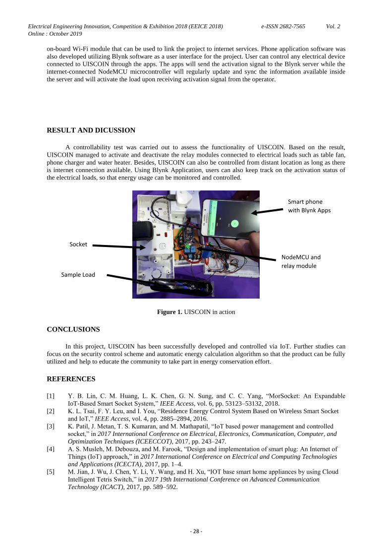
RESULT AND DICUSSION
A controllability test was carried out to assess the functionality of UISCOIN. Based on the result,
UISCOIN managed to activate and deactivate the relay modules connected to electrical loads such as table fan,
phone charger and water heater. Besides, UISCOIN can also be controlled from distant location as long as there
is internet connection available. Using Blynk Application, users can also keep track on the activation status of
the electrical loads, so that energy usage can be monitored and controlled.
Figure 1. UISCOIN in action
CONCLUSIONS
In this project, UISCOIN has been successfully developed and controlled via IoT. Further studies can
focus on the security control scheme and automatic energy calculation algorithm so that the product can be fully
utilized and help to educate the community to take part in energy conservation effort.
REFERENCES
[1] Y. B. Lin, C. M. Huang, L. K. Chen, G. N. Sung, and C. C. Yang, “MorSocket: An Expandable
IoT-Based Smart Socket System,” IEEE Access, vol. 6, pp. 53123–53132, 2018.
[2] K. L. Tsai, F. Y. Leu, and I. You, “Residence Energy Control System Based on Wireless Smart Socket
and IoT,” IEEE Access, vol. 4, pp. 2885–2894, 2016.
[3] K. Patil, J. Metan, T. S. Kumaran, and M. Mathapatil, “IoT based power management and controlled
socket,” in 2017 International Conference on Electrical, Electronics, Communication, Computer, and
Optimization Techniques (ICEECCOT), 2017, pp. 243–247.
[4] A. S. Musleh, M. Debouza, and M. Farook, “Design and implementation of smart plug: An Internet of
Things (IoT) approach,” in 2017 International Conference on Electrical and Computing Technologies
and Applications (ICECTA), 2017, pp. 1–4.
[5] M. Jian, J. Wu, J. Chen, Y. Li, Y. Wang, and H. Xu, “IOT base smart home appliances by using Cloud
Intelligent Tetris Switch,” in 2017 19th International Conference on Advanced Communication
Technology (ICACT), 2017, pp. 589–592.
Smart phone
with Blynk Apps
Socket
Sample Load
NodeMCU and
relay module