Embed Size (px)
Citation preview

Memory management is one of the most important and most difficult duties of anoperating system. This chapter presents a comprehensive overview of Windows
2000 memory management and the structure of the 4-GB linear address space. In thiscontext, the virtual memory addressing and paging capabilities of the Intel i386 CPUfamily are explained, focusing on how the Windows 2000 kernel exploits them. Toaid the exploration of memory, this chapter features a pair of sample programs: akernel-mode device driver that collects information about the system, and a user-mode client application that queries this data from the driver via device I/O controland displays it in a console window. The “spy driver” module will be reused in theremaining chapters for several other interesting tasks that require execution of ker-nel-mode code. This chapter—especially the first section—is tough reading becauseit puts your hands directly on the CPU hardware. Nevertheless I hope you won’t skip it,because virtual memory management is an exciting topic, and understanding howit works provides insight into the mechanics of a complex operating system such asWindows 2000.
INTEL i386 MEMORY MANAGEMENT
The Windows 2000 kernel makes heavy use of the protected-mode virtual memorymanagement mechanisms of the Intel i386 CPU class. To get a better understandingof how Windows 2000 manages its main memory, it is important to be at least mini-mally familiar with some architectural issues of the i386 CPU. The term i386 mightlook somewhat anachronistic because the 80386 CPU dates back to the early days ofWindows computing. Windows 2000 is designed for Pentium CPUs and above.However, even these newer processors rely on the memory management model origi-nally designed for the 80386 CPU, with some important enhancements, of course.Therefore, Microsoft usually labels the Windows NT and 2000 versions built for
161
C H A P T E R 4
ExploringWindows 2000Memory

Intel processors “i386” or even “x86.” Don’t be confused about that—whenever youread the numbers 86 or 386 in this book, keep in mind that the corresponding infor-mation refers to a specific CPU architecture, not a specific processor release.
BASIC MEMORY LAYOUT
Windows 2000 uses a very straightforward memory layout for application and sys-tem code. The 4-GB virtual memory space offered by the 32-bit Intel CPUs is dividedinto two equal parts. Memory addresses below 0x80000000 are assigned to user-mode modules, including the Win32 subsystem, and the remaining 2 GB are reservedfor the kernel. Windows 2000 Advanced Server also supports an alternative memorymodel commonly called 4GT RAM Tuning, which has been introduced with Win-dows NT 4.0 Server Enterprise Edition. This model features 3-GB address space foruser processes, and 1-GB space for the kernel. It is enabled by adding the /3GB switchto the bootstrap command line in the boot manager configuration file boot.ini.
The Advanced Server and Datacenter variants of Windows 2000 support yetanother memory option named Physical Address Extension (PAE) enabled by theboot.ini switch /PAE. This option exploits a feature of some Intel CPUs(e.g., the Pentium Pro processor) that allows physical memory larger than 4 GB tobe mapped into the 32-bit address space. In this Chapter, I will ignore these specialconfigurations. You can read more about them in Microsoft’s Knowledge Basearticle Q171793 (Microsoft 2000c), Intel’s Pentium manuals (Intel 1999a, 1999b,1999c), and the Windows 2000 Device Driver Kit (DDK) documentation(Microsoft 2000f).
MEMORY SEGMENTATION AND DEMAND PAGING
Before delving into the technical details of the i386 architecture, let’s travel back intime to the year 1978, when Intel released the mother of all PC processors: the 8086.I want to restrict this discussion to the most significant milestones. If you want toknow more, Robert L. Hummel’s 80486 programmer’s reference is an excellent start-ing point (Hummel 1992). It is a bit outdated now because it doesn’t cover the newfeatures of the Pentium family; however, this leaves more space for important infor-mation about the basic i386 architecture. Although the 8086 was able to address 1MB of Random Access Memory (RAM), an application could never “see” the entirephysical address space because of the restriction of the CPU’s address registers to 16bits. This means that applications were able to access a contiguous linear addressspace of only 64 KB, but this memory window could be shifted up and down in thephysical space with the help of a set of 16-bit segment registers. Each segment regis-ter defined a base address in 16-byte increments, and the linear addresses in the64-KB logical space were added as offsets to this base, effectively resulting in 20-bit
162 EXPLORING WINDOWS 2000 MEMORY
addresses. This archaic memory model is still supported even by the latest PentiumCPUs, and it is called Real-Address Mode, commonly referred to as Real Mode.
An alternative mode was introduced with the 80286 CPU, referred to as Protected Virtual Address Mode, or simply Protected Mode. It featured a memorymodel where physical addresses were not generated by simply adding a linear addressto a segment base. To retain backward compatibility with the 8086 and 80186, the80286 still used segment registers, but they did not contain physical segment addressesafter the CPU had been switched to Protected Mode. Instead, they provided a selector,comprising an index into a descriptor table. The target entry defined a 24-bit physicalbase address, allowing access to 16 MB of RAM, which seemed like an incredibleamount then. However, the 80286 was still a 16-bit CPU, so the limitation of the linear address space to 64 KB tiles still applied.
The breakthrough came in 1985 with the 80386 CPU. This chip finally cut theties of 16-bit addressing, pushing up the linear address space to 4 GB by introducing32-bit linear addresses while retaining the basic selector/descriptor architecture of itspredecessor. Fortunately, the 80286 descriptor structure contained some spare bits thatcould be reclaimed. While moving from 16- to 32-bit addresses, the size of the CPU’sdata registers was doubled as well, and new powerful addressing modes were added.This radical shift to 32-bit data and addresses was a real benefit for programmers—at least theoretically. Practically, it took several years longer before the MicrosoftWindows platform was ready to fully support the 32-bit model. The first version ofWindows NT was released on July 26th, 1993, constituting the very first incarnationof the Win32 API. Whereas Windows 3.x programmers still had to deal with mem-ory tiles of 64 KB with separate code and data segments, Windows NT provided aflat linear address space of 4 GB, where all code and data could be addressed bysimple 32-bit pointers, without segmentation. Internally, of course, segmentationwas still active, as I will show later in this chapter, but the entire responsibility formanaging segments finally had been moved to the operating system.
Another essential new 80386 feature was the hardware support for paging, or,more precisely, demand-paged virtual memory. This is a technique that allows mem-ory to be backed up by a storage medium other than RAM—a hard disk, for exam-ple. With paging enabled, the CPU can access more memory than physically availableby swapping out the least recently accessed memory contents to backup storage,making space for new data. Theoretically, up to 4 GB of contiguous linear memorycan be accessed this way, provided that the backup media is large enough—even ifthe installed physical RAM amounts to just a small fraction of the memory. Ofcourse, paging is not the fastest way to access memory. It is always good to have asmuch physical RAM as possible. But it is an excellent way to work with largeamounts of data that would otherwise exceed the available memory. For example,graphics and database applications require a large amount of working memory, andsome wouldn’t be able to run on a low-end PC system if paging weren’t available.
INTEL i386 MEMORY MANAGEMENT 163
In the paging scheme of the 80386, memory is subdivided into pages of 4-KBor 4-MB size. The operating system designer is free to choose between these twooptions, and it is even possible to mix pages of both sizes. Later I will show thatWindows 2000 uses such a mixed page design, keeping the operating system in4-MB pages and using 4-KB pages for the remaining code and data. The pages aremanaged by means of a hierarchically structured page-table tree that indicates foreach page where it is currently located in physical memory. This managementstructure also contains information on whether the page is actually in physicalmemory in the first place. If a page has been swapped out to the hard disk, andsome module touches an address within this page, the CPU generates a page fault,similar to an interrupt generated by a peripheral hardware device. Next, the pagefault handler inside the operating system kernel will attempt to swap back thispage to physical memory, possibly writing other memory contents to disk to makespace. Usually, the system will apply a least-recently-used (LRU) schedule to decidewhich pages qualify to be swapped out. By now it should be clear why this proce-dure is sometimes referred to as demand paging: Physical memory contents aremoved to the backup storage and back on software demand, based on statistics ofthe memory usage of the operating system and its applications.
The address indirection layer represented by the page-tables has two interest-ing implications. First, there is no predetermined relationship between the addressesused by a program and the addresses found on the physical address bus of the CPUchip. If you know that a data structure of your application is located at the address,say, 0x00140000, you still don’t know anything about the physical address of yourdata unless you examine the page-table tree. It is up to the operating system todecide what this address mapping looks like. Even more, the address translationcurrently in effect is unpredictable, in part because of the probabilistic nature of thepaging mechanism. Fortunately, knowledge of physical addresses isn’t required inmost application cases. This is something left for developers of hardware drivers.The second implication of paging is that the address space is not necessarily contigu-ous. Depending on the page-table contents, the 4-GB space can comprise large“holes” where neither physical nor backup memory is mapped. If an applicationtries to read to or write from such an address, it will be aborted immediately by thesystem. Later in this chapter, I will show in detail how Windows 2000 spreads itsavailable memory over the 4-GB address space.
The 80486 and Pentium CPUs use the very same i386 segmentation and pagingmechanisms introduced with the 80386, except for some exotic addressing featuressuch as the Physical Address Extension (PAE) of the Pentium Pro. Along with higherclock frequencies, these newer models contain optimizations in other areas. Forexample, the Pentium features a dual instruction pipeline that enables it to execute
164 EXPLORING WINDOWS 2000 MEMORY
two operations at the same time, as long as these instructions don’t depend on eachother. For example, if instruction A modifies a register value, and the consecutiveinstruction B uses the modified value for a computation, B cannot be executedbefore A has finished. But if instruction B involves a different register, the CPU canexecute A and B simultaneously without adverse effects. This and other Pentiumoptimizations have opened a wide field for compiler optimization. If this topic looksinteresting, see Rick Booth’s Inner Loops (Booth 1997).
In the context of i386 memory management, three sorts of addresses must bedistinguished, termed logical, linear, and physical addresses in Intel’s system pro-gramming manual for the Pentium (Intel 1999c).
1. Logical addresses: This is the most precise specification of a memorylocation, usually written in hexadecimal form as XXXX:YYYYYYYY, whereXXXX is a selector, and YYYYYYYY is a linear offset into the segment addressedby the selector. Instead of a numeric XXXX value, it is also possible tospecify the name of a segment register holding the selector, such as CS(code segment), DS (data segment), ES (extra segment), FS (additional datasegment #1), GS (additional data segment #2), and SS (stack segment). Thisnotation is borrowed from the old “segment:offset” style of specifying “farpointers” in 8086 Real-Mode.
2. Linear addresses: Most applications and many kernel-mode driversdisregard virtual addresses. More precisely, they are just interested in theoffset part of a virtual address, which is referred to as a linear address. Anaddress of this type assumes a default segmentation model, determined bythe current values of the CPU’s segment registers. Windows 2000 uses flatsegmentation, with the CS, DS, ES, and SS registers pointing to the samelinear address space; therefore, programs can safely assume that all code,data, and stack pointers can be cast among one another. For example, astack location can be cast to a data pointer at any time without concernabout the values of the corresponding segment registers.
3. Physical addresses: This address type is of interest only if the CPUworks in paging mode. Basically, a physical address is the voltage patternmeasurable at the address bus pins of the CPU chip. The operating systemmaps linear addresses to physical addresses by setting up page-tables. Thelayout of the Windows 2000 page-tables, which has some very interestingproperties for debugging software developers, will be discussed later inthis chapter.
INTEL i386 MEMORY MANAGEMENT 165

The distinction between virtual and linear addresses is somewhat artificial, andsome documentation uses both terms interchangeably. I will do my best to use thisnomenclature consistently. It is important to note that Windows 2000 assumes physi-cal addresses to be 64 bits wide. This might seem odd on Intel i386 systems, whichusually have a 32-bit address bus. However, some Pentium systems can address morethan 4 GB of physical memory. For example, the Physical Address Extension (PAE)mode of the Pentium Pro CPU extends the physical address space to 36 bits, allowingaccess to 64 GB of RAM (Intel 1999c). Therefore, the Windows 2000 API functionsinvolving physical addresses usually rely on the data type PHYSICAL_ADDRESS, whichis just an alias name for the LARGE_INTEGER structure, as shown in Listing 4-1. Bothtypes are defined in the DDK header file ntdef.h. The LARGE_INTEGER is a structuralrepresentation of a 64-bit signed integer, allowing interpretation as a concatenation oftwo 32-bit quantities (LowPart and HighPart) or a single 64-bit number (QuadPart).The LONGLONG type is equivalent to the native Visual C/C++ type __int64. Itsunsigned sibling is called ULONGLONG or DWORDLONG and is based on the nativeunsigned __int64 type.
Figure 4-1 outlines the i386 memory segmentation model, showing the relation-ship between logical and linear addresses. For clarity, I have drawn the descriptortable and the segment as small, nonoverlapping boxes. However, this isn’t a require-ment. Actually, a 32-bit operating system usually applies a segmentation layout asshown in Figure 4-2. This so-called flat memory model is based on segments thatspan the entire 4-GB address space. As a side effect, the descriptor table becomes partof the segment and can be accessed by all code that has sufficient access rights.
166 EXPLORING WINDOWS 2000 MEMORY
typedef LARGE_INTEGER PHYSICAL_ADDRESS, *PPHYSICAL_ADDRESS;
typedef union _LARGE_INTEGER
{
struct
{
ULONG LowPart;
LONG HighPart;
};
LONGLONG QuadPart;
}
LARGE_INTEGER, *PLARGE_INTEGER;
LISTING 4-1. Definition of PHYSICAL_ADDRESS and LARGE_INTEGER
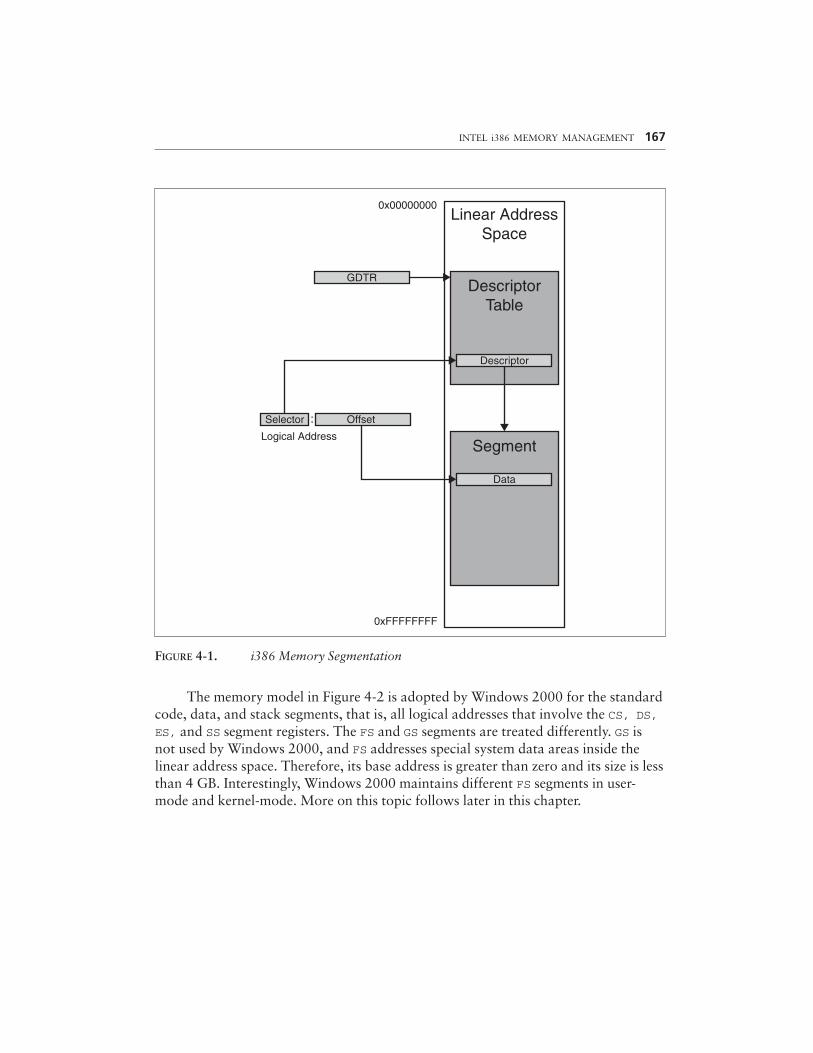
FIGURE 4-1. i386 Memory Segmentation
The memory model in Figure 4-2 is adopted by Windows 2000 for the standardcode, data, and stack segments, that is, all logical addresses that involve the CS, DS,ES, and SS segment registers. The FS and GS segments are treated differently. GS isnot used by Windows 2000, and FS addresses special system data areas inside thelinear address space. Therefore, its base address is greater than zero and its size is lessthan 4 GB. Interestingly, Windows 2000 maintains different FS segments in user-mode and kernel-mode. More on this topic follows later in this chapter.
INTEL i386 MEMORY MANAGEMENT 167
0x00000000Linear Address
Space
GDTRDescriptor
Table
Descriptor
OffsetSelector
Logical AddressSegment
Data
0xFFFFFFFF
:
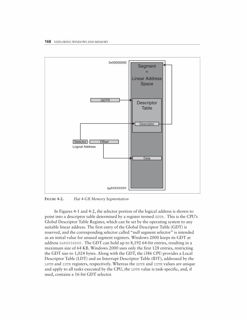
FIGURE 4-2. Flat 4-GB Memory Segmentation
In Figures 4-1 and 4-2, the selector portion of the logical address is shown topoint into a descriptor table determined by a register termed GDTR. This is the CPU’sGlobal Descriptor Table Register, which can be set by the operating system to anysuitable linear address. The first entry of the Global Descriptor Table (GDT) isreserved, and the corresponding selector called “null segment selector” is intendedas an initial value for unused segment registers. Windows 2000 keeps its GDT ataddress 0x80036000. The GDT can hold up to 8,192 64-bit entries, resulting in amaximum size of 64 KB. Windows 2000 uses only the first 128 entries, restrictingthe GDT size to 1,024 bytes. Along with the GDT, the i386 CPU provides a LocalDescriptor Table (LDT) and an Interrupt Descriptor Table (IDT), addressed by theLDTR and IDTR registers, respectively. Whereas the GDTR and IDTR values are uniqueand apply to all tasks executed by the CPU, the LDTR value is task-specific, and, ifused, contains a 16-bit GDT selector.
168 EXPLORING WINDOWS 2000 MEMORY
0x00000000
Linear AddressSpace
GDTRDescriptor
Table
Descriptor
OffsetSelector
Logical Address
Data
0xFFFFFFFF
Segment=
:
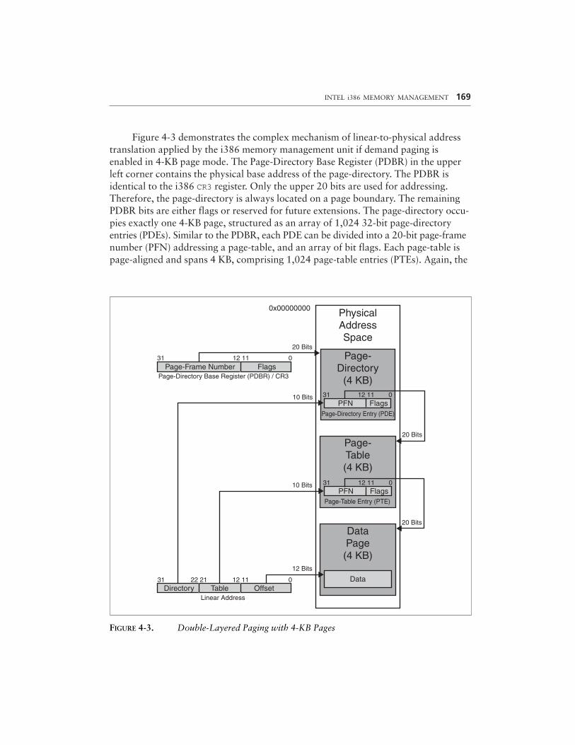
Figure 4-3 demonstrates the complex mechanism of linear-to-physical addresstranslation applied by the i386 memory management unit if demand paging isenabled in 4-KB page mode. The Page-Directory Base Register (PDBR) in the upperleft corner contains the physical base address of the page-directory. The PDBR isidentical to the i386 CR3 register. Only the upper 20 bits are used for addressing.Therefore, the page-directory is always located on a page boundary. The remainingPDBR bits are either flags or reserved for future extensions. The page-directory occu-pies exactly one 4-KB page, structured as an array of 1,024 32-bit page-directoryentries (PDEs). Similar to the PDBR, each PDE can be divided into a 20-bit page-framenumber (PFN) addressing a page-table, and an array of bit flags. Each page-table ispage-aligned and spans 4 KB, comprising 1,024 page-table entries (PTEs). Again, the
INTEL i386 MEMORY MANAGEMENT 169
0x00000000
Page-Directory
(4 KB)
PhysicalAddressSpace
Page-Table(4 KB)
DataPage(4 KB)
20 Bits
12 1131
Page-Directory Base Register (PDBR) / CR3
10 Bits
Page-Frame Number Flags0
10 Bits
12 Bits
012 1122 2131
Linear Address
DataOffsetTableDirectory
PFN Flags
PFN FlagsPage-Directory Entry (PDE)
31 12 11 0
Page-Table Entry (PTE)
31 12 11 0
20 Bits
20 Bits
FIGURE 4-3. Double-Layered Paging with 4-KB Pages
upper 20 bits are extracted from a PTE to form a pointer to a 4-KB data page.Address translation takes place by breaking a linear address into three parts: Theupper 10 bits select a PDE out of the page-directory, the next lower 10 bits select aPTE out of the page-table addressed by the PDE, and, finally, the lower 12 bits spec-ify an offset into the data page addressed by the PTE.
In the 4-KB paging scheme, the 4-GB linear address space is addressable bymeans of a double-layered indirection mechanism. In the worst case, 1,048,576 PTEsare required to cover the entire range. Because each page-table holds 1,024 PTEs, thisamounts to 1,024 page-tables, which is the number of PDEs the page-directory con-tains. With the page-directory and each page-table consuming 4 KB, the maximummemory management overhead in this paging model is 4 KB plus 4 MB, or 4,100 KB.That’s a reasonable price for a subdivision of the entire 4-GB space into 4-KB tilesthat can be mapped to any linear address.
In 4-MB paging mode, things are much simpler because one indirection layer iseliminated, as shown in Figure 4-4. Again, the PDBR points to the page-directory,but now only the upper 10 bits of the PDE are used, resulting in 4-MB alignment ofthe target address. Because no page-tables are used, this address is already the baseaddress of a 4-MB data page. Consequently, the linear address now consists of twoparts only: 10 bits for PDE selection and 22 offset bits. The 4-MB memory schemerequires no more than 4 KB overhead, because only the page-directory consumesadditional memory. Each of its 1,024 PDEs can address one 4-MB page. This is justenough to cover the entire 4-GB address space. Thus, 4-MB pages have the advan-tage of keeping the memory management overhead low, but for the price of a morecoarse addressing granularity.
Both the 4-KB and 4-MB paging modes have advantages and disadvantages.Fortunately, operating system designers don’t have to decide for one of them, but canrun the CPU in mixed mode. For example, Windows 2000 works with 4-MB pages inthe memory range 0x80000000 to 0x9FFFFFFF, where the kernel modules hal.dlland ntoskrnl.exe are loaded. The remaining linear address blocks are managed in4-KB tiles. This mixed design is recommended by Intel for improved system perfor-mance, because 4-KB and 4-MB page entries are cached in different TranslationLookaside Buffers (TLBs) inside the i386 CPU (Intel 1999c, pp. 3-22f). The operatingsystem kernel is usually large and is always resident in memory, so storing it in sev-eral 4-KB pages would permanently use up valuable TLB space.
Note that all address translation steps are carried out in physical memory. ThePDBR and all PDEs and PTEs contain physical address pointers. The only linear addressfound in Figures 4-3 and 4-4 is the box in the lower left corner specifying the address tobe converted to an offset inside a physical page. On the other hand, applications mustwork with linear addresses and are ignorant of physical addresses. However, it ispossible to fill this gap by mapping the page-directory and all of its subordinate page-tables into the linear address space. On Windows 2000 and Windows NT 4.0, all
170 EXPLORING WINDOWS 2000 MEMORY
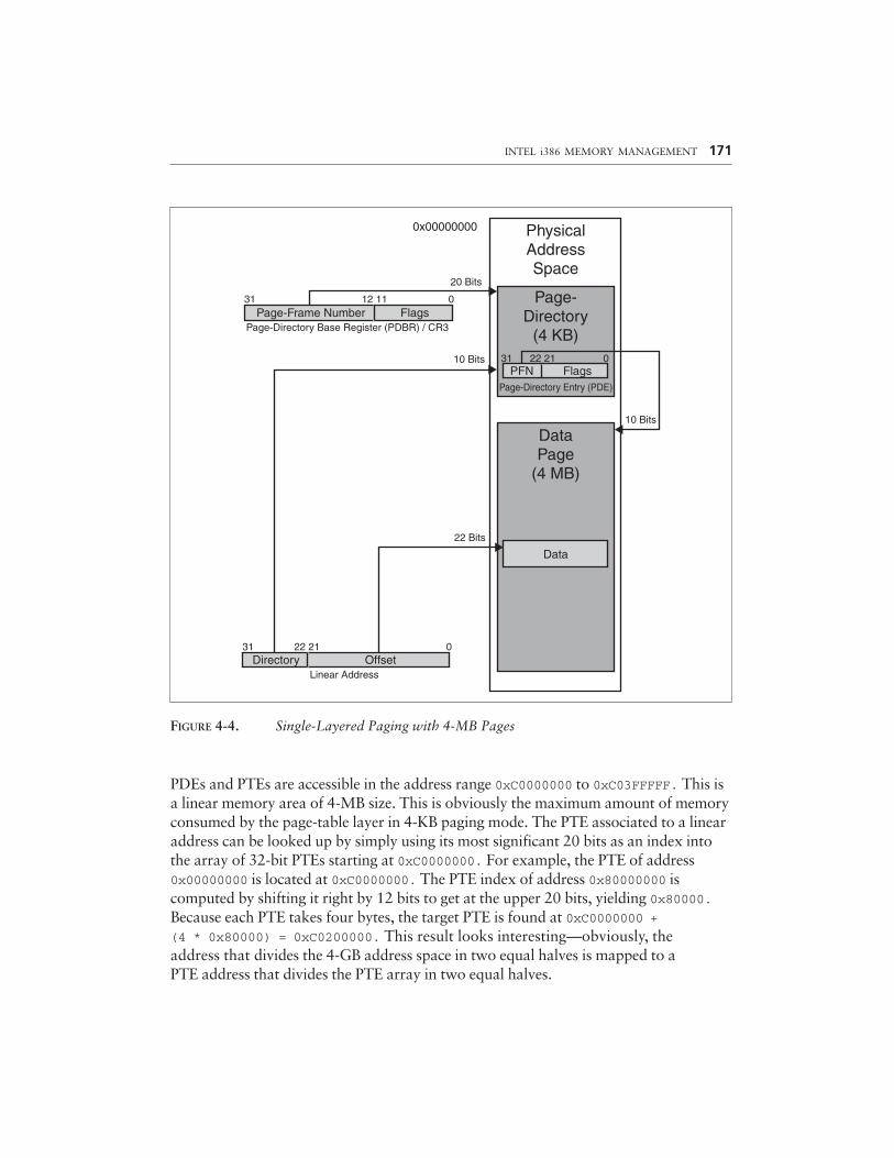
FIGURE 4-4. Single-Layered Paging with 4-MB Pages
PDEs and PTEs are accessible in the address range 0xC0000000 to 0xC03FFFFF. This isa linear memory area of 4-MB size. This is obviously the maximum amount of memoryconsumed by the page-table layer in 4-KB paging mode. The PTE associated to a linearaddress can be looked up by simply using its most significant 20 bits as an index intothe array of 32-bit PTEs starting at 0xC0000000. For example, the PTE of address0x00000000 is located at 0xC0000000. The PTE index of address 0x80000000 iscomputed by shifting it right by 12 bits to get at the upper 20 bits, yielding 0x80000.Because each PTE takes four bytes, the target PTE is found at 0xC0000000 + (4 * 0x80000) = 0xC0200000. This result looks interesting—obviously, theaddress that divides the 4-GB address space in two equal halves is mapped to aPTE address that divides the PTE array in two equal halves.
INTEL i386 MEMORY MANAGEMENT 171
Flags
0x00000000
Page-Directory
(4 KB)
PhysicalAddressSpace
20 Bits
12 1131
Page-Directory Base Register (PDBR) / CR3
10 Bits
Page-Frame Number Flags0
22 Bits
022 2131
Linear AddressOffsetDirectory
PFN FlagsPage-Directory Entry (PDE)
31 22 21 0
10 Bits
DataPage
(4 MB)
Data
Now let’s go one more step ahead and compute the entry address of the PTEarray itself. The general mapping formula is ((LinearAddress >> 12) * 4) +0xC0000000. Setting LinearAddress to 0xC0000000 yields 0xC0300000. Let’s pausefor a moment: The entry at linear address 0xC0300000 points to the beginning of thePTE array in physical memory. Now look back to Figure 4-3. The 1,024 entries start-ing at address 0xC0300000 must be the page-directory! This special PDE and PTEarrangement is exploited by various memory management functions implemented inntoskrnl.exe. For example, the (documented) API functions MmIsAddressValid()and MmGetPhysicalAddress() take a 32-bit linear address, look up its PDE and, ifapplicable, its PTE, and examine their contents. MmIsAddressValid() simply checksout whether the target page is currently present in physical memory. If the test fails,the linear address is either invalid or it refers to a page that has been flushed tobackup storage, represented by the set of system pagefiles. MmGetPhysicalAddress()first extracts the page-frame number (PFN) corresponding to a linear address, whichis the base address of its associated physical page divided by the page size. Next, itcomputes the offset into this page by extracting the least significant 12 bits of the lin-ear address, and adds the offset to the physical base address determined by the PFN.
More thorough examination of the implementation of MmGetPhysicalAddress()reveals another interesting property of the Windows 2000 memory layout. Before any-thing else, the code tests whether the linear address is within the range 0x80000000 to0x9FFFFFFF. As already mentioned, this is the home of hal.dll and ntoskrnl.exe,and it is also the address block where Windows 2000 uses 4-MB pages. The interestingthing is that MmGetPhysicalAddress() doesn’t care at all for PDEs or PTEs if theaddress is within this range. Instead, it simply sets the top three bits to zero, adds thebyte offset, as usual, and returns the result as the physical address. This means thatthe physical address range 0x00000000 to 0x1FFFFFFF is mapped 1:1 to the linearaddresses 0x80000000 to 9FFFFFFF! Knowing that ntoskrnl.exe is always loaded tothe linear address 0x80400000, this means that the Windows 2000 kernel is alwaysfound at physical address 0x00400000, which happens to be the base address of thesecond 4-MB page in physical memory. In fact, examination of these memory regionsproves that the above assumptions are correct. You will have the opportunity to seethis with the memory spy presented in this chapter.
DATA STRUCTURES
Some portions of the sample code following in this chapter are concerned with low-level memory management and peek inside the mechanisms outlined above. For con-venience, I have defined several C data structures that make this task easier. Becausemany data items inside the i386 CPU are concatenations of single bits or bit groups,C bit-fields come in handy. Bit-fields are an efficient way to access individual bits ofor extract contiguous bit groups from larger data words. Microsoft Visual C/C++
172 EXPLORING WINDOWS 2000 MEMORY
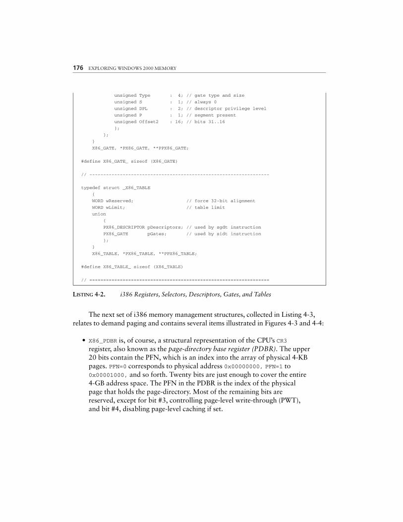
generates quite clever code for bit-field operations. Listing 4-2 is part one of a seriesof CPU data type definitions, containing the following items:
• X86_REGISTER is a basic unsigned 32-bit integral type that can representvarious CPU registers. This comprises all general-purpose, index, pointer,control, debug, and test registers.
• X86_SELECTOR represents a 16-bit segment selector, as stored in thesegment registers CS, DS, ES, FS, GS, and SS. In Figures 4-1 and 4-2,selectors are depicted as the upper third of a logical 48-bit address, servingas an index into a descriptor table. For computational convenience, the16-bit selector value is extended to 32 bits, with the upper half marked“reserved.” Note that the X86_SELECTOR structure is a union of twostructures. The first one specifies the selector value as a packed 16-bit WORDnamed wValue, and the second breaks it up into bit-fields. The RPL fieldspecifies the Requested Privilege Level, which is either 0 (kernel-mode) or3 (user-mode) on Windows 2000. The TI bit switches between the Globaland Local Descriptor Tables (GDT/LDT).
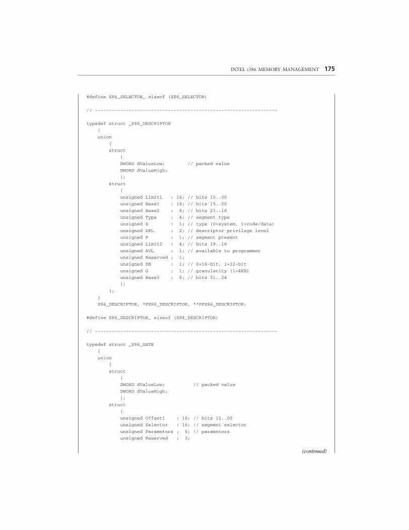
• X86_DESCRIPTOR defines the format of a table entry pointed to by aselector. It is a 64-bit quantity with a very convoluted structure resultingfrom its historic evolution. The linear base address defining the startlocation of the associated segment is scattered among three bit-fieldsnamed Base1, Base2, and Base3, with Base1 being the least significantpart. The segment limit specifying the segment size minus one is dividedinto the pair Limit1 and Limit2, with the former representing the leastsignificant half. The remaining bit-fields store various segmentproperties (cf. Intel 1999c, pp. 3-11). For example, the G bit definesthe segment granularity. If zero, the segment limit is specified in bytes;otherwise, the limit value has to be multiplied by 4 KB. Like X86_SELECTOR,the X86_DESCRIPTOR structure is composed of a union to allow differentinterpretations of its value. The dValueLow and dValueHigh membersare helpful if you have to copy descriptors without regard to theirinternal structure.
• X86_GATE looks somewhat similar to X86_DESCRIPTOR. In fact, thestructures are related: X86_DESCRIPTOR is a GDT entry and describes thememory properties of a segment, and X86_GATE is an entry inside theInterrupt Descriptor Table (IDT) and describes the memory properties ofan interrupt handler. The IDT can contain task, interrupt, and trap gates.(No, Bill Gates is not stored in the IDT!) The X86_GATE structure matchesall three types, with the Type bit-field determining the identity. Type 5
INTEL i386 MEMORY MANAGEMENT 173
identifies a task gate; types 6 and 14, interrupt gates; and types 7 and 15,trap gates. The most significant type bit specifies the size of the gate:16-bit gates have this bit set to zero; otherwise it is a 32-bit gate.
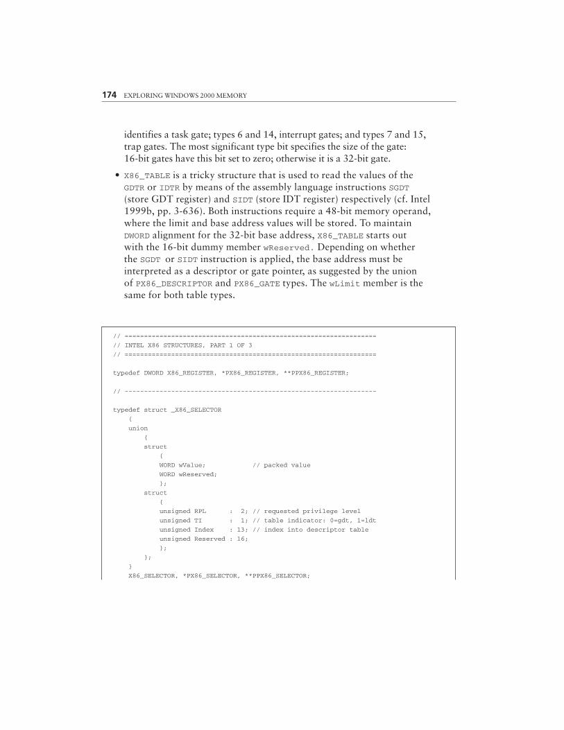
• X86_TABLE is a tricky structure that is used to read the values of theGDTR or IDTR by means of the assembly language instructions SGDT(store GDT register) and SIDT (store IDT register) respectively (cf. Intel1999b, pp. 3-636). Both instructions require a 48-bit memory operand,where the limit and base address values will be stored. To maintainDWORD alignment for the 32-bit base address, X86_TABLE starts outwith the 16-bit dummy member wReserved. Depending on whetherthe SGDT or SIDT instruction is applied, the base address must beinterpreted as a descriptor or gate pointer, as suggested by the unionof PX86_DESCRIPTOR and PX86_GATE types. The wLimit member is thesame for both table types.
174 EXPLORING WINDOWS 2000 MEMORY
// =================================================================
// INTEL X86 STRUCTURES, PART 1 OF 3
// =================================================================
typedef DWORD X86_REGISTER, *PX86_REGISTER, **PPX86_REGISTER;
// -----------------------------------------------------------------
typedef struct _X86_SELECTOR
{
union
{
struct
{
WORD wValue; // packed value
WORD wReserved;
};
struct
{
unsigned RPL : 2; // requested privilege level
unsigned TI : 1; // table indicator: 0=gdt, 1=ldt
unsigned Index : 13; // index into descriptor table
unsigned Reserved : 16;
};
};
}
X86_SELECTOR, *PX86_SELECTOR, **PPX86_SELECTOR;
INTEL i386 MEMORY MANAGEMENT 175
#define X86_SELECTOR_ sizeof (X86_SELECTOR)
// -----------------------------------------------------------------
typedef struct _X86_DESCRIPTOR
{
union
{
struct
{
DWORD dValueLow; // packed value
DWORD dValueHigh;
};
struct
{
unsigned Limit1 : 16; // bits 15..00
unsigned Base1 : 16; // bits 15..00
unsigned Base2 : 8; // bits 23..16
unsigned Type : 4; // segment type
unsigned S : 1; // type (0=system, 1=code/data)
unsigned DPL : 2; // descriptor privilege level
unsigned P : 1; // segment present
unsigned Limit2 : 4; // bits 19..16
unsigned AVL : 1; // available to programmer
unsigned Reserved : 1;
unsigned DB : 1; // 0=16-bit, 1=32-bit
unsigned G : 1; // granularity (1=4KB)
unsigned Base3 : 8; // bits 31..24
};
};
}
X86_DESCRIPTOR, *PX86_DESCRIPTOR, **PPX86_DESCRIPTOR;
#define X86_DESCRIPTOR_ sizeof (X86_DESCRIPTOR)
// -----------------------------------------------------------------
typedef struct _X86_GATE
{
union
{
struct
{
DWORD dValueLow; // packed value
DWORD dValueHigh;
};
struct
{
unsigned Offset1 : 16; // bits 15..00
unsigned Selector : 16; // segment selector
unsigned Parameters : 5; // parameters
unsigned Reserved : 3;
(continued)
176 EXPLORING WINDOWS 2000 MEMORY
unsigned Type : 4; // gate type and size
unsigned S : 1; // always 0
unsigned DPL : 2; // descriptor privilege level
unsigned P : 1; // segment present
unsigned Offset2 : 16; // bits 31..16
};
};
}
X86_GATE, *PX86_GATE, **PPX86_GATE;
#define X86_GATE_ sizeof (X86_GATE)
// -----------------------------------------------------------------
typedef struct _X86_TABLE
{
WORD wReserved; // force 32-bit alignment
WORD wLimit; // table limit
union
{
PX86_DESCRIPTOR pDescriptors; // used by sgdt instruction
PX86_GATE pGates; // used by sidt instruction
};
}
X86_TABLE, *PX86_TABLE, **PPX86_TABLE;
#define X86_TABLE_ sizeof (X86_TABLE)
// =================================================================
LISTING 4-2. i386 Registers, Selectors, Descriptors, Gates, and Tables
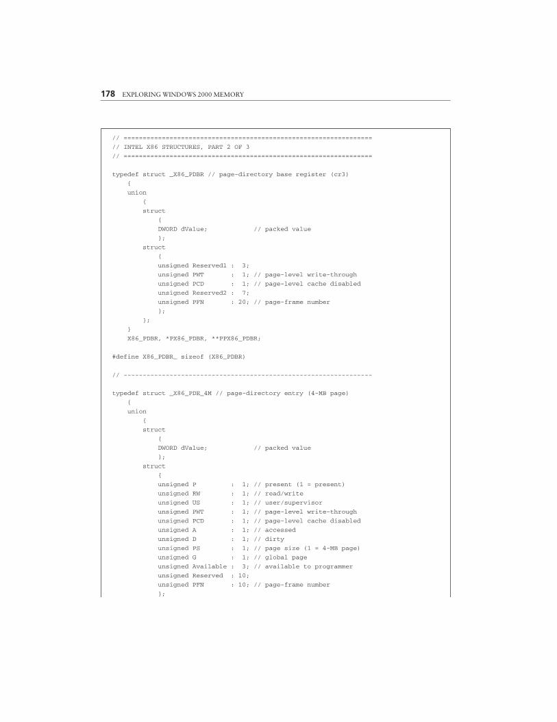
The next set of i386 memory management structures, collected in Listing 4-3,relates to demand paging and contains several items illustrated in Figures 4-3 and 4-4:
• X86_PDBR is, of course, a structural representation of the CPU’s CR3register, also known as the page-directory base register (PDBR). The upper20 bits contain the PFN, which is an index into the array of physical 4-KBpages. PFN=0 corresponds to physical address 0x00000000, PFN=1 to0x00001000, and so forth. Twenty bits are just enough to cover the entire4-GB address space. The PFN in the PDBR is the index of the physicalpage that holds the page-directory. Most of the remaining bits arereserved, except for bit #3, controlling page-level write-through (PWT),and bit #4, disabling page-level caching if set.
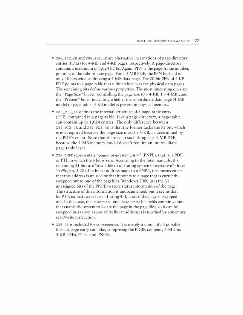
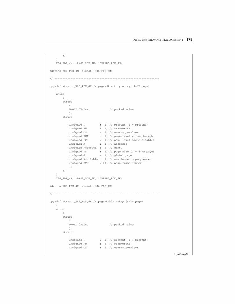
• X86_PDE_4M and X86_PDE_4K are alternative incarnations of page-directoryentries (PDEs) for 4-MB and 4-KB pages, respectively. A page-directorycontains a maximum of 1,024 PDEs. Again, PFN is the page-frame number,pointing to the subordinate page. For a 4-MB PDE, the PFN bit-field isonly 10 bits wide, addressing a 4-MB data page. The 20-bit PFN of 4-KBPDE points to a page-table that ultimately selects the physical data pages.The remaining bits define various properties. The most interesting ones arethe “Page Size” bit PS, controlling the page size (0 = 4-KB, 1 = 4-MB), andthe “Present” bit P, indicating whether the subordinate data page (4-MBmode) or page-table (4-KB mode) is present in physical memory.
• X86_PTE_4K defines the internal structure of a page-table entry(PTE) contained in a page-table. Like a page-directory, a page-tablecan contain up to 1,024 entries. The only difference betweenX86_PTE_4K and X86_PDE_4K is that the former lacks the PS bit, whichis not required because the page size must be 4-KB, as determined bythe PDE’s PS bit. Note that there is no such thing as a 4-MB PTE,because the 4-MB memory model doesn’t require an intermediatepage-table layer.
• X86_PNPE represents a “page-not-present entry” (PNPE), that is, a PDEor PTE in which the P bit is zero. According to the Intel manuals, theremaining 31 bits are “available to operating system or executive” (Intel1999c, pp. 3-28). If a linear address maps to a PNPE, this means eitherthat this address is unused or that it points to a page that is currentlyswapped out to one of the pagefiles. Windows 2000 uses the 31unassigned bits of the PNPE to store status information of the page.The structure of this information is undocumented, but it seems thatbit #10, named PageFile in Listing 4-3, is set if the page is swappedout. In this case, the Reserved1 and Reserved2 bit-fields contain valuesthat enable the system to locate the page in the pagefiles, so it can beswapped in as soon as one of its linear addresses is touched by a memoryread/write instruction.
• X86_PE is included for convenience. It is merely a union of all possibleforms a page entry can take, comprising the PDBR contents, 4-MB and4-KB PDEs, PTEs, and PNPEs.
INTEL i386 MEMORY MANAGEMENT 177
178 EXPLORING WINDOWS 2000 MEMORY
// =================================================================
// INTEL X86 STRUCTURES, PART 2 OF 3
// =================================================================
typedef struct _X86_PDBR // page-directory base register (cr3)
{
union
{
struct
{
DWORD dValue; // packed value
};
struct
{
unsigned Reserved1 : 3;
unsigned PWT : 1; // page-level write-through
unsigned PCD : 1; // page-level cache disabled
unsigned Reserved2 : 7;
unsigned PFN : 20; // page-frame number
};
};
}
X86_PDBR, *PX86_PDBR, **PPX86_PDBR;
#define X86_PDBR_ sizeof (X86_PDBR)
// -----------------------------------------------------------------
typedef struct _X86_PDE_4M // page-directory entry (4-MB page)
{
union
{
struct
{
DWORD dValue; // packed value
};
struct
{
unsigned P : 1; // present (1 = present)
unsigned RW : 1; // read/write
unsigned US : 1; // user/supervisor
unsigned PWT : 1; // page-level write-through
unsigned PCD : 1; // page-level cache disabled
unsigned A : 1; // accessed
unsigned D : 1; // dirty
unsigned PS : 1; // page size (1 = 4-MB page)
unsigned G : 1; // global page
unsigned Available : 3; // available to programmer
unsigned Reserved : 10;
unsigned PFN : 10; // page-frame number
};
INTEL i386 MEMORY MANAGEMENT 179
};
}
X86_PDE_4M, *PX86_PDE_4M, **PPX86_PDE_4M;
#define X86_PDE_4M_ sizeof (X86_PDE_4M)
// -----------------------------------------------------------------
typedef struct _X86_PDE_4K // page-directory entry (4-KB page)
{
union
{
struct
{
DWORD dValue; // packed value
};
struct
{
unsigned P : 1; // present (1 = present)
unsigned RW : 1; // read/write
unsigned US : 1; // user/supervisor
unsigned PWT : 1; // page-level write-through
unsigned PCD : 1; // page-level cache disabled
unsigned A : 1; // accessed
unsigned Reserved : 1; // dirty
unsigned PS : 1; // page size (0 = 4-KB page)
unsigned G : 1; // global page
unsigned Available : 3; // available to programmer
unsigned PFN : 20; // page-frame number
};
};
}
X86_PDE_4K, *PX86_PDE_4K, **PPX86_PDE_4K;
#define X86_PDE_4K_ sizeof (X86_PDE_4K)
// -----------------------------------------------------------------
typedef struct _X86_PTE_4K // page-table entry (4-KB page)
{
union
{
struct
{
DWORD dValue; // packed value
};
struct
{
unsigned P : 1; // present (1 = present)
unsigned RW : 1; // read/write
unsigned US : 1; // user/supervisor
(continued)
180 EXPLORING WINDOWS 2000 MEMORY
unsigned PWT : 1; // page-level write-through
unsigned PCD : 1; // page-level cache disabled
unsigned A : 1; // accessed
unsigned D : 1; // dirty
unsigned Reserved : 1;
unsigned G : 1; // global page
unsigned Available : 3; // available to programmer
unsigned PFN : 20; // page-frame number
};
};
}
X86_PTE_4K, *PX86_PTE_4K, **PPX86_PTE_4K;
#define X86_PTE_4K_ sizeof (X86_PTE_4K)
// -----------------------------------------------------------------
typedef struct _X86_PNPE // page not present entry
{
union
{
struct
{
DWORD dValue; // packed value
};
struct
{
unsigned P : 1; // present (0 = not present)
unsigned Reserved1 : 9;
unsigned PageFile : 1; // page swapped to pagefile
unsigned Reserved2 : 21;
};
};
}
X86_PNPE, *PX86_PNPE, **PPX86_PNPE;
#define X86_PNPE_ sizeof (X86_PNPE)
// -----------------------------------------------------------------
typedef struct _X86_PE // general page entry
{
union
{
DWORD dValue; // packed value
X86_PDBR pdbr; // page-directory Base Register
X86_PDE_4M pde4M; // page-directory entry (4-MB page)
X86_PDE_4K pde4K; // page-directory entry (4-KB page)
X86_PTE_4K pte4K; // page-table entry (4-KB page)
X86_PNPE pnpe; // page not present entry
};
INTEL i386 MEMORY MANAGEMENT 181
}
X86_PE, *PX86_PE, **PPX86_PE;
#define X86_PE_ sizeof (X86_PE)
// =================================================================
LISTING 4-3. i386 PDBR, PDE, PTE, and PNPE Values
In Listing 4-4, I have added structural representations of linear addresses.These structures are formal definitions of the “Linear Address” boxes in Figures 4-3and 4-4:
• X86_LINEAR_4M is the format of linear addresses that point into a 4-MBdata page, as shown in Figure 4-4. The page-directory index PDI is anindex into the page-directory currently addressed by the PDBR, selectingone of its PDEs. The 22-bit Offset member points to the target addresswithin the corresponding 4-MB physical page.
• X86_LINEAR_4K is the 4-KB variant of a linear address. As outlined inFigure 4-3, it is composed of three bit-fields: Like in a 4-MB address, theupper 10 PDI bits select a PDE. The page-table index PTI has a similarduty, pointing to a PTE inside the page-table addressed by this PDE. Theremaining 12 bits are the offset into the resulting 4-KB physical page.
• X86_LINEAR is another convenience structure that simply unitesX86_LINEAR_4M and X86_LINEAR_4K in a single data type.
MACROS AND CONSTANTS
The definitions in Listing 4-5 are supplements to the structures in Listings 4-2 to 4-4and make the work with i386 memory management easier. They can be subdividedinto three main groups. The first group handles linear addresses:
1. X86_PAGE_MASK, X86_PDI_MASK, and X86_PTI_MASK are bit masks thatisolate the constituent parts of linear addresses. They are based on theconstants PAGE_SHIFT (12), PDI-SHIFT (22), and PTI-SHIFT (12),defined in the Windows 2000 DDK header file ntddk.h. X86_PAGE_MASKevaluates to 0xFFFFF000, effectively masking off the 4-KB offset part of alinear address (cf. X86_LINEAR_4K). X86_PDI_MASK is equal to 0xFFC00000and obviously extracts the 10 topmost PDI bits of a linear address (cf.X86_LINEAR_4M and X86_LINEAR_4K). X86_PTI_MASK evaluates to0x003FF0000 and masks off all bits except for the page-table index (PTI) bits of a linear address (cf. X86_LINEAR_4K).
182 EXPLORING WINDOWS 2000 MEMORY
// =================================================================
// INTEL X86 STRUCTURES, PART 3 OF 3
// =================================================================
typedef struct _X86_LINEAR_4M // linear address (4-MB page)
{
union
{
struct
{
PVOID pAddress; // packed address
};
struct
{
unsigned Offset : 22; // offset into page
unsigned PDI : 10; // page-directory index
};
};
}
X86_LINEAR_4M, *PX86_LINEAR_4M, **PPX86_LINEAR_4M;
#define X86_LINEAR_4M_ sizeof (X86_LINEAR_4M)
// -----------------------------------------------------------------
typedef struct _X86_LINEAR_4K // linear address (4-KB page)
{
union
{
struct
{
PVOID pAddress; // packed address
};
struct
{
unsigned Offset : 12; // offset into page
unsigned PTI : 10; // page-table index
unsigned PDI : 10; // page-directory index
};
};
}
X86_LINEAR_4K, *PX86_LINEAR_4K, **PPX86_LINEAR_4K;
#define X86_LINEAR_4K_ sizeof (X86_LINEAR_4K)
// -----------------------------------------------------------------
typedef struct _X86_LINEAR // general linear address
{
union
{
INTEL i386 MEMORY MANAGEMENT 183
PVOID pAddress; // packed address
X86_LINEAR_4M linear4M; // linear address (4-MB page)
X86_LINEAR_4K linear4K; // linear address (4-KB page)
};
}
X86_LINEAR, *PX86_LINEAR, **PPX86_LINEAR;
#define X86_LINEAR_ sizeof (X86_LINEAR)
// =================================================================
LISTING 4-4. i386 Linear Addresses
2. X86_PAGE(), X86_PDI(), and X86_PTI() use the above constantsto compute the page index, PDI, or PTI of a given linear address.X86_PAGE() is typically used to read a PTE from the Windows 2000 PTEarray starting at address 0xC0000000. X86_PDI() and X86_PTI() simplyapply X86_PDI_MASK or X86_PTI_ MASK to the supplied pointer and shiftthe resulting index to the rightmost bit position.
3. X86_OFFSET_4M() and X86_OFFSET_4K() extract the offset portion of a4-MB or 4-KB linear address, respectively.
4. X86_PAGE_4M and X86_PAGE_4K compute the sizes of 4-MB and 4-KBpages from the DDK constants PDI_SHIFT and PTI_SHIFT, resultingin X86_PAGE_4M = 4,194,304 and X86_PAGE_4K = 4,096. Note thatX86_PAGE_4K is equivalent to the DDK constant PAGE_SIZE, alsodefined in ntddk.h.
5. X86_PAGES_4M and X86_PAGES_4K state the number of 4-MB or 4-KBpages fitting into the 4-GB linear address space. X86_PAGES_4M evaluatesto 1,024, and X86_PAGES_4K to 1,048,576.
The second group of macros and constants relates to the Windows 2000 PDEand PTE arrays. Unlike several other system addresses, the base addresses of thesearrays are not available as global variables set up at boot time, but are defined asconstants. This can be proved easily by disassembling the memory manager APIfunctions MmGetPhysicalAddress() or MmIsAddressValid(), where these addressesappear as “magic numbers.” These constants are not included in the DDK headerfiles, but Listing 4-5 shows how they might have been defined.
• X86_PAGES is a hard-coded address and points, of course, to 0xC0000000,where the Windows 2000 PTE array starts.
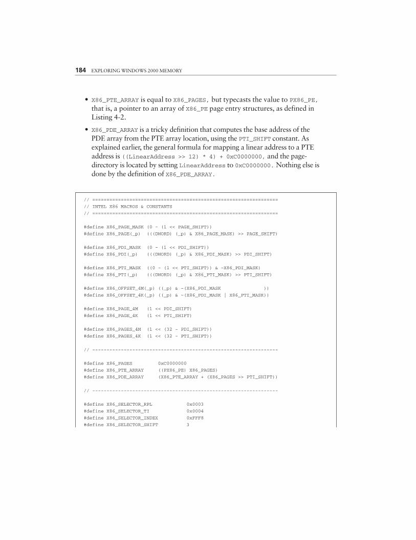
• X86_PTE_ARRAY is equal to X86_PAGES, but typecasts the value to PX86_PE,that is, a pointer to an array of X86_PE page entry structures, as defined inListing 4-2.
• X86_PDE_ARRAY is a tricky definition that computes the base address of thePDE array from the PTE array location, using the PTI_SHIFT constant. Asexplained earlier, the general formula for mapping a linear address to a PTEaddress is ((LinearAddress >> 12) * 4) + 0xC0000000, and the page-directory is located by setting LinearAddress to 0xC0000000. Nothing else isdone by the definition of X86_PDE_ARRAY.
184 EXPLORING WINDOWS 2000 MEMORY
// =================================================================
// INTEL X86 MACROS & CONSTANTS
// =================================================================
#define X86_PAGE_MASK (0 - (1 << PAGE_SHIFT))
#define X86_PAGE(_p) (((DWORD) (_p) & X86_PAGE_MASK) >> PAGE_SHIFT)
#define X86_PDI_MASK (0 - (1 << PDI_SHIFT))
#define X86_PDI(_p) (((DWORD) (_p) & X86_PDI_MASK) >> PDI_SHIFT)
#define X86_PTI_MASK ((0 - (1 << PTI_SHIFT)) & ~X86_PDI_MASK)
#define X86_PTI(_p) (((DWORD) (_p) & X86_PTI_MASK) >> PTI_SHIFT)
#define X86_OFFSET_4M(_p) ((_p) & ~(X86_PDI_MASK ))
#define X86_OFFSET_4K(_p) ((_p) & ~(X86_PDI_MASK | X86_PTI_MASK))
#define X86_PAGE_4M (1 << PDI_SHIFT)
#define X86_PAGE_4K (1 << PTI_SHIFT)
#define X86_PAGES_4M (1 << (32 - PDI_SHIFT))
#define X86_PAGES_4K (1 << (32 - PTI_SHIFT))
// -----------------------------------------------------------------
#define X86_PAGES 0xC0000000
#define X86_PTE_ARRAY ((PX86_PE) X86_PAGES)
#define X86_PDE_ARRAY (X86_PTE_ARRAY + (X86_PAGES >> PTI_SHIFT))
// -----------------------------------------------------------------
#define X86_SELECTOR_RPL 0x0003
#define X86_SELECTOR_TI 0x0004
#define X86_SELECTOR_INDEX 0xFFF8
#define X86_SELECTOR_SHIFT 3

INTEL i386 MEMORY MANAGEMENT 185
#define X86_SELECTOR_LIMIT (X86_SELECTOR_INDEX >> \
X86_SELECTOR_SHIFT)
// -----------------------------------------------------------------
#define X86_DESCRIPTOR_SYS_TSS16A 0x1
#define X86_DESCRIPTOR_SYS_LDT 0x2
#define X86_DESCRIPTOR_SYS_TSS16B 0x3
#define X86_DESCRIPTOR_SYS_CALL16 0x4
#define X86_DESCRIPTOR_SYS_TASK 0x5
#define X86_DESCRIPTOR_SYS_INT16 0x6
#define X86_DESCRIPTOR_SYS_TRAP16 0x7
#define X86_DESCRIPTOR_SYS_TSS32A 0x9
#define X86_DESCRIPTOR_SYS_TSS32B 0xB
#define X86_DESCRIPTOR_SYS_CALL32 0xC
#define X86_DESCRIPTOR_SYS_INT32 0xE
#define X86_DESCRIPTOR_SYS_TRAP32 0xF
// -----------------------------------------------------------------
#define X86_DESCRIPTOR_APP_ACCESSED 0x1
#define X86_DESCRIPTOR_APP_READ_WRITE 0x2
#define X86_DESCRIPTOR_APP_EXECUTE_READ 0x2
#define X86_DESCRIPTOR_APP_EXPAND_DOWN 0x4
#define X86_DESCRIPTOR_APP_CONFORMING 0x4
#define X86_DESCRIPTOR_APP_CODE 0x8
// =================================================================
LISTING 4-5. Additional i386 Memory Management Definitions
The last two sections of Listing 4-5 handle selectors and special types ofdescriptors, and are complementary to Listing 4-2:
• X86_SELECTOR_RPL, X86_SELECTOR_TI, and X86_SELECTOR_INDEXare bit masks corresponding to the RPL, TI, and Index members of theX86_SELECTOR structures defined in Listing 4-2.
• X86_SELECTOR_SHIFT is a right-shift factor that right-aligns the value ofthe selector’s Index member.
• X86_SELECTOR_LIMIT defines the maximum index value a selector canhold and is equal to 8,191. This value determines the maximum size of adescriptor table. Each selector index points to a descriptor, and eachdescriptor consists of 64 bits or 8 bytes (cf. X86_DESCRIPTOR in Listing 4-2),so the maximum descriptor table size amounts to 8,192 * 8 = 64 KB.
• The list of X86_DESCRIPTOR_SYS_* constants define values of adescriptor’s Type member if its S-bit is zero, identifying it as a systemdescriptor. Please refer to Listing 4-2 for the bit-field layout of a descriptor,determined by the structure X86_DESCRIPTOR. The system descriptor typesare described in detail in the Intel manuals (Intel 1999c, pp. 3-15f) andsummarized in Table 4-1.
The X86_DESCRIPTOR_APP_* constants concluding Listing 4-5 apply to adescriptor’s Type member if it is an application descriptor referring to a code ordata segment, identified by a nonzero S-bit. Because application descriptor typescan be characterized by independent properties reflected by the four type bits, theX86_DESCRIPTOR_APP_* constants are defined as single-bit masks, in which somebits are interpreted differently for data and code segments:
• X86_DESCRIPTOR_APP_ACCESSED is set if the segment has been accessed.
• X86_DESCRIPTOR_APP_READ_WRITE decides whether a data segment allowsread-only or read/write access.
• X86_DESCRIPTOR_APP_EXECUTE_READ decides whether a code segmentallows execute-only or execute/read access.
• X86_DESCRIPTOR_APP_DOWN is set for expand-down data segments, whichis a property commonly exposed by stack segments.
• X86_DESCRIPTOR_APP_CONFORMING indicates whether a code segment isconforming, that is, whether it can be called by less privileged code(cf. Intel 1999c, pp. 4-13ff).
• X86_DESCRIPTOR_APP_CODE distinguishes code and data segments. Notethat stack segments belong to the data segment category and must alwaysbe writable.
We will revisit system descriptors later when the memory spy application pre-sented in the next sections is up and running. Table 4-1 also concludes a short intro-duction to i386 memory management. For more information on this topic, pleaserefer to the original Intel Pentium manuals (Intel 1999a, 1999b, 1999c) or one of thesecondary readings, such as Robert L. Hummel’s great 80486 reference handbook(Hummel 1992).
186 EXPLORING WINDOWS 2000 MEMORY
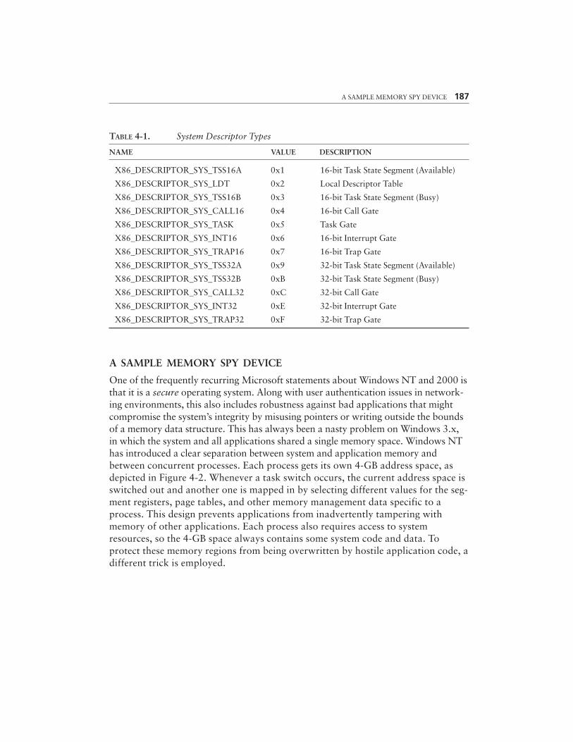
TABLE 4-1. System Descriptor Types
NAME VALUE DESCRIPTION
X86_DESCRIPTOR_SYS_TSS16A 0x1 16-bit Task State Segment (Available)
X86_DESCRIPTOR_SYS_LDT 0x2 Local Descriptor Table
X86_DESCRIPTOR_SYS_TSS16B 0x3 16-bit Task State Segment (Busy)
X86_DESCRIPTOR_SYS_CALL16 0x4 16-bit Call Gate
X86_DESCRIPTOR_SYS_TASK 0x5 Task Gate
X86_DESCRIPTOR_SYS_INT16 0x6 16-bit Interrupt Gate
X86_DESCRIPTOR_SYS_TRAP16 0x7 16-bit Trap Gate
X86_DESCRIPTOR_SYS_TSS32A 0x9 32-bit Task State Segment (Available)
X86_DESCRIPTOR_SYS_TSS32B 0xB 32-bit Task State Segment (Busy)
X86_DESCRIPTOR_SYS_CALL32 0xC 32-bit Call Gate
X86_DESCRIPTOR_SYS_INT32 0xE 32-bit Interrupt Gate
X86_DESCRIPTOR_SYS_TRAP32 0xF 32-bit Trap Gate
A SAMPLE MEMORY SPY DEVICE
One of the frequently recurring Microsoft statements about Windows NT and 2000 isthat it is a secure operating system. Along with user authentication issues in network-ing environments, this also includes robustness against bad applications that mightcompromise the system’s integrity by misusing pointers or writing outside the boundsof a memory data structure. This has always been a nasty problem on Windows 3.x,in which the system and all applications shared a single memory space. Windows NThas introduced a clear separation between system and application memory andbetween concurrent processes. Each process gets its own 4-GB address space, asdepicted in Figure 4-2. Whenever a task switch occurs, the current address space isswitched out and another one is mapped in by selecting different values for the seg-ment registers, page tables, and other memory management data specific to aprocess. This design prevents applications from inadvertently tampering withmemory of other applications. Each process also requires access to systemresources, so the 4-GB space always contains some system code and data. Toprotect these memory regions from being overwritten by hostile application code, adifferent trick is employed.
A SAMPLE MEMORY SPY DEVICE 187
WINDOWS 2000 MEMORY SEGMENTATION
Windows 2000 has inherited the basic memory segmentation scheme of WindowsNT 4.0, which divides the 4-GB process address space in two equal parts by default.The lower half, comprising the range 0x00000000 to 0x7FFFFFFF, contains applica-tion data and code running in user-mode, which is equivalent to Privilege Level 3 or“Ring 3” in Intel’s terminology (Intel 1999a, pp. 4-8ff; Intel 1999c, pp. 4-8ff). Theupper half, ranging from 0x80000000 to 0xFFFFFFFF, is reserved for the system,which is running in kernel-mode, also known as Intel’s Privilege Level 0 or “Ring 0.”The privilege level determines what operations may be executed and which memorylocations can be accessed by the code. Especially, this means that certain CPUinstructions are forbidden and certain memory regions are inaccessible, for low-privileged code. For example, if a user-mode application touches any address inthe upper half of the 4-GB address space, the system will throw an exception andterminate the application process without giving it another chance.
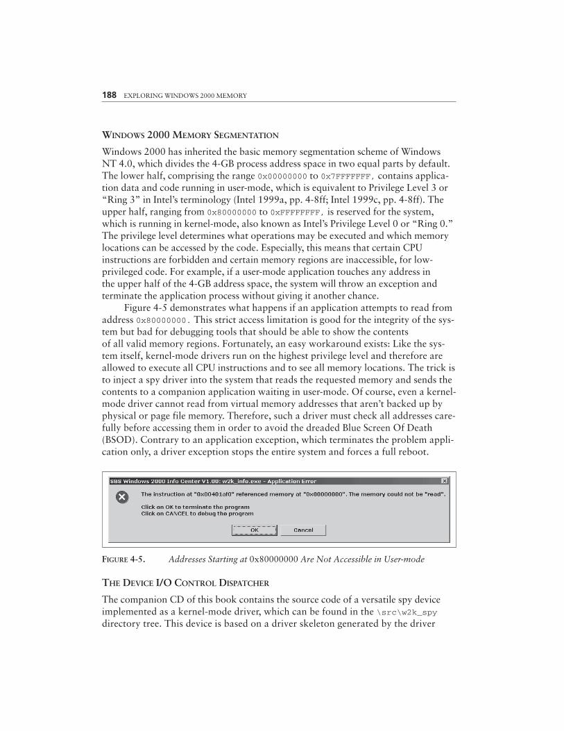
Figure 4-5 demonstrates what happens if an application attempts to read fromaddress 0x80000000. This strict access limitation is good for the integrity of the sys-tem but bad for debugging tools that should be able to show the contentsof all valid memory regions. Fortunately, an easy workaround exists: Like the sys-tem itself, kernel-mode drivers run on the highest privilege level and therefore areallowed to execute all CPU instructions and to see all memory locations. The trick isto inject a spy driver into the system that reads the requested memory and sends thecontents to a companion application waiting in user-mode. Of course, even a kernel-mode driver cannot read from virtual memory addresses that aren’t backed up byphysical or page file memory. Therefore, such a driver must check all addresses care-fully before accessing them in order to avoid the dreaded Blue Screen Of Death(BSOD). Contrary to an application exception, which terminates the problem appli-cation only, a driver exception stops the entire system and forces a full reboot.
188 EXPLORING WINDOWS 2000 MEMORY
FIGURE 4-5. Addresses Starting at 0x80000000 Are Not Accessible in User-mode
THE DEVICE I/O CONTROL DISPATCHER
The companion CD of this book contains the source code of a versatile spy deviceimplemented as a kernel-mode driver, which can be found in the \src\w2k_spydirectory tree. This device is based on a driver skeleton generated by the driver
wizard introduced in Chapter 3. The user-mode interface of w2k_spy.sys is based onWin32 Device I/O Control (IOCTL), briefly described in the same chapter. The spydriver defines a device named \Device\w2k_spy and a symbolic link, \DosDevices\w2k_spy, required to make the device reachable from user-mode. It is funny that thenamespace of symbolic links is called \DosDevices. We are certainly not workingwith DOS device drivers here. This name has historic roots and is now set in stone.With the symbolic link installed, the driver can be opened by any user-mode modulevia the standard Win32 API function CreateFile(), using the path \\.\w2k_spy.The character sequence \\.\ is a general escape for local devices. For example,\\.\C: refers to hard disk C: of the local system. See the CreateFile() documen-tation in the Microsoft Platform SDK for more details.
Parts of the driver’s header file w2k_spy.h are included above as Listings 4-2to 4-5. This file is somewhat similar to a DLL header file: It contains definitionsrequired by the module itself during compilation, but it also provides enough infor-mation for a client application that needs to interface to it. Both the DLL/driverand the client application include the same header file, and each module picks outthe definitions it needs for proper operation. However, this Janus-headed natureof the header file creates many more problems for a kernel-mode driver than fora DLL because of the special development environment Microsoft provides for dri-vers. Unfortunately, the header files contained in the DDK are not compatible withthe Win32 files in the Platform SDK. The header files cannot be mixed, at least notin C language projects, resulting in a deadlocked situation in which the kernel-mode driver has access to constants, macros, and data types not available to theclient application, and vice versa. Therefore, w2k_spy.c defines a flag constantnamed _W2K_SPY_SYS_, and w2k_spy.h checks the presence or absence of this con-stant to define items that are missing in one or the other environment, using#ifdef...#else...#endif clauses. This means that all definitions found in the#ifdef _W2K_SPY_SYS_ branch are “seen” by the driver code only, whereas the defini-tions in the #else branch are evaluated exclusively by the client application. All partsof w2k_spy.h outside these conditional clauses apply to both modules.
In Chapter 3, in the discussion of my driver wizard, I presented the driver skeletoncode provided by the wizard in Listing 3-3. The starting point of any new driver projectcreated by this wizard is usually the DeviceDispatcher() function. It receives a devicecontext pointer and a pointer to the I/O Request Packet (IRP) that is to be dispatched.The wizard’s boilerplate code already handles the basic I/O requests IRP_MJ_CREATE,IRP_MJ_CLEANUP, and IRP_MJ_CLOSE, sent to the device when it is opened or closed bya client. The DeviceDispatcher() simply returns STATUS_SUCCESS for these requests,so the device can be opened and closed without error. For some devices, this behavior issufficient, but others require more or less complex initialization and cleanup code here.All remaining requests return STATUS_NOT_IMPLEMENTED. The first step in the extensionof the code is to change this default behavior by handling more requests. As already
A SAMPLE MEMORY SPY DEVICE 189
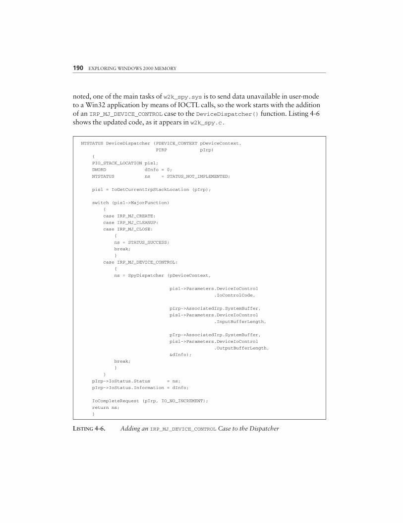
noted, one of the main tasks of w2k_spy.sys is to send data unavailable in user-modeto a Win32 application by means of IOCTL calls, so the work starts with the additionof an IRP_MJ_DEVICE_CONTROL case to the DeviceDispatcher() function. Listing 4-6shows the updated code, as it appears in w2k_spy.c.
190 EXPLORING WINDOWS 2000 MEMORY
NTSTATUS DeviceDispatcher (PDEVICE_CONTEXT pDeviceContext,
PIRP pIrp)
{
PIO_STACK_LOCATION pisl;
DWORD dInfo = 0;
NTSTATUS ns = STATUS_NOT_IMPLEMENTED;
pisl = IoGetCurrentIrpStackLocation (pIrp);
switch (pisl->MajorFunction)
{
case IRP_MJ_CREATE:
case IRP_MJ_CLEANUP:
case IRP_MJ_CLOSE:
{
ns = STATUS_SUCCESS;
break;
}
case IRP_MJ_DEVICE_CONTROL:
{
ns = SpyDispatcher (pDeviceContext,
pisl->Parameters.DeviceIoControl
.IoControlCode,
pIrp->AssociatedIrp.SystemBuffer,
pisl->Parameters.DeviceIoControl
.InputBufferLength,
pIrp->AssociatedIrp.SystemBuffer,
pisl->Parameters.DeviceIoControl
.OutputBufferLength,
&dInfo);
break;
}
}
pIrp->IoStatus.Status = ns;
pIrp->IoStatus.Information = dInfo;
IoCompleteRequest (pIrp, IO_NO_INCREMENT);
return ns;
}
LISTING 4-6. Adding an IRP_MJ_DEVICE_CONTROL Case to the Dispatcher
A SAMPLE MEMORY SPY DEVICE 191
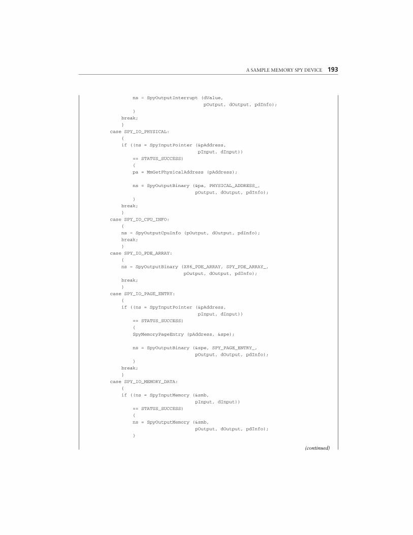
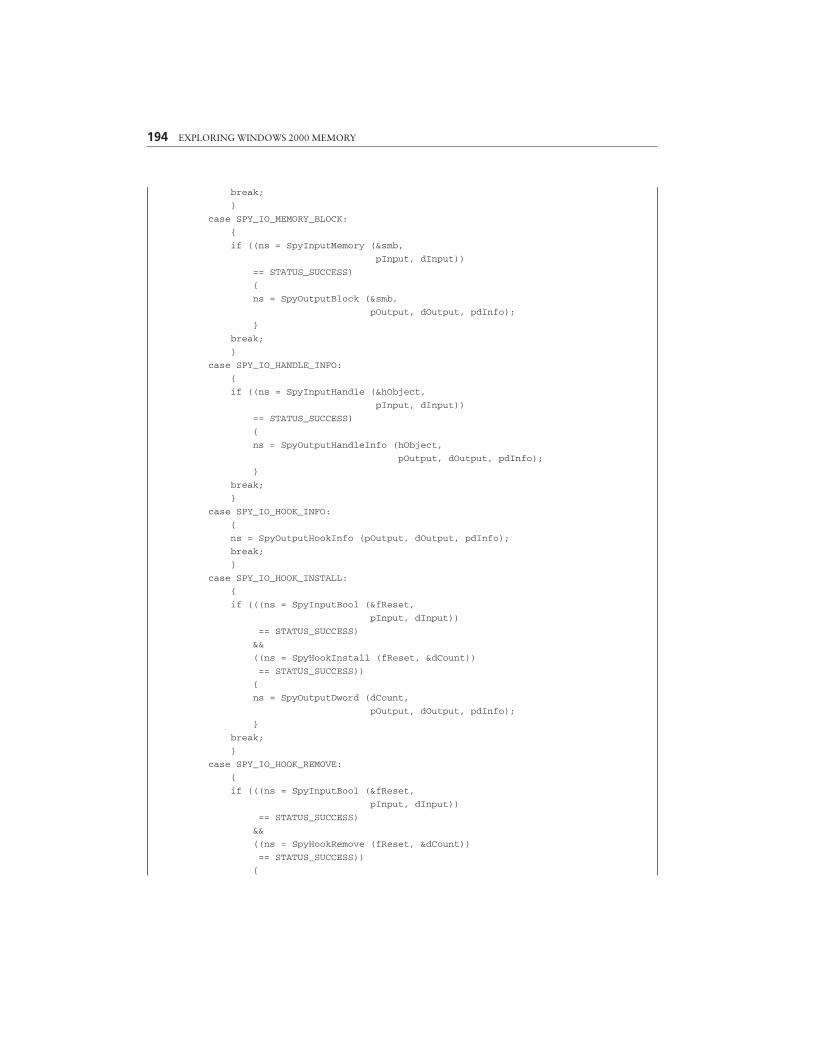
The IOCTL handler in Listing 4-6 is fairly simple—it just calls SpyDispatcher()with parameters it extracts from the IRP structure and the current I/O stack locationembedded in it. The SpyDispatcher(), shown in Listing 4-7, requires the followingarguments:
• pDeviceContext is the driver’s device context. The basic Device_Contextstructure provided by the driver wizard contains the driver and device objectpointers only (see Listing 3-4). The spy driver adds a couple of members to itfor private use.
• dCode specifies the IOCTL code that determines the command to beexecuted by the spy device. An IOCTL code is a 32-bit integer consistingof 4 bit-fields, as illustrated by Figure 4-6.
• pInput points to the buffer providing the IOCTL input data.
• dInput is the size of the input buffer.
• pOutput points to the buffer receiving the IOCTL output data.
• dOutput is the size of the output buffer.
• pdInfo points to a DWORD variable that should receive the number of byteswritten to the output buffer.
Depending on the IOCTL method used, the input and output buffers arepassed differently from the system to the driver. The spy device uses buffered I/O,directing the system to copy the input data to a safe buffer allocated automaticallyby the system, and to copy a specified amount of data from the same system bufferto the caller’s output buffer on return. It is important to keep in mind that the inputand output buffers overlap in this case, so the IOCTL handler must save any inputdata it might need later before it writes any output data to the buffer. The pointer tothis I/O buffer is stored in the SystemBuffer member of the AssociatedIrp unioninside the IRP structure (cf. ntddk.h). The input and output buffer sizes are storedin a completely different location of the IRP—they are part of the DeviceIoControlmember of the Parameters union inside the IRP’s current stack location, namedInputBufferLength and OutputBufferLength, respectively. The DeviceIoControlsubstructure also provides the IOCTL code via its IoControlCode member. Moreinformation about the Windows NT/2000 IOCTL methods and how they pass datain and out can be found in my article “A Spy Filter Driver for Windows NT” inWindows Developer’s Journal (Schreiber 1997).

192 EXPLORING WINDOWS 2000 MEMORY
NTSTATUS SpyDispatcher (PDEVICE_CONTEXT pDeviceContext,
DWORD dCode,
PVOID pInput,
DWORD dInput,
PVOID pOutput,
DWORD dOutput,
PDWORD pdInfo)
{
SPY_MEMORY_BLOCK smb;
SPY_PAGE_ENTRY spe;
SPY_CALL_INPUT sci;
PHYSICAL_ADDRESS pa;
DWORD dValue, dCount;
BOOL fReset, fPause, fFilter, fLine;
PVOID pAddress;
PBYTE pbName;
HANDLE hObject;
NTSTATUS ns = STATUS_INVALID_PARAMETER;
MUTEX_WAIT (pDeviceContext->kmDispatch);
*pdInfo = 0;
switch (dCode)
{
case SPY_IO_VERSION_INFO:
{
ns = SpyOutputVersionInfo (pOutput, dOutput, pdInfo);
break;
}
case SPY_IO_OS_INFO:
{
ns = SpyOutputOsInfo (pOutput, dOutput, pdInfo);
break;
}
case SPY_IO_SEGMENT:
{
if ((ns = SpyInputDword (&dValue,
pInput, dInput))
== STATUS_SUCCESS)
{
ns = SpyOutputSegment (dValue,
pOutput, dOutput, pdInfo);
}
break;
}
case SPY_IO_INTERRUPT:
{
if ((ns = SpyInputDword (&dValue,
pInput, dInput))
== STATUS_SUCCESS)
{
A SAMPLE MEMORY SPY DEVICE 193
ns = SpyOutputInterrupt (dValue,
pOutput, dOutput, pdInfo);
}
break;
}
case SPY_IO_PHYSICAL:
{
if ((ns = SpyInputPointer (&pAddress,
pInput, dInput))
== STATUS_SUCCESS)
{
pa = MmGetPhysicalAddress (pAddress);
ns = SpyOutputBinary (&pa, PHYSICAL_ADDRESS_,
pOutput, dOutput, pdInfo);
}
break;
}
case SPY_IO_CPU_INFO:
{
ns = SpyOutputCpuInfo (pOutput, dOutput, pdInfo);
break;
}
case SPY_IO_PDE_ARRAY:
{
ns = SpyOutputBinary (X86_PDE_ARRAY, SPY_PDE_ARRAY_,
pOutput, dOutput, pdInfo);
break;
}
case SPY_IO_PAGE_ENTRY:
{
if ((ns = SpyInputPointer (&pAddress,
pInput, dInput))
== STATUS_SUCCESS)
{
SpyMemoryPageEntry (pAddress, &spe);
ns = SpyOutputBinary (&spe, SPY_PAGE_ENTRY_,
pOutput, dOutput, pdInfo);
}
break;
}
case SPY_IO_MEMORY_DATA:
{
if ((ns = SpyInputMemory (&smb,
pInput, dInput))
== STATUS_SUCCESS)
{
ns = SpyOutputMemory (&smb,
pOutput, dOutput, pdInfo);
}
(continued)
194 EXPLORING WINDOWS 2000 MEMORY
break;
}
case SPY_IO_MEMORY_BLOCK:
{
if ((ns = SpyInputMemory (&smb,
pInput, dInput))
== STATUS_SUCCESS)
{
ns = SpyOutputBlock (&smb,
pOutput, dOutput, pdInfo);
}
break;
}
case SPY_IO_HANDLE_INFO:
{
if ((ns = SpyInputHandle (&hObject,
pInput, dInput))
== STATUS_SUCCESS)
{
ns = SpyOutputHandleInfo (hObject,
pOutput, dOutput, pdInfo);
}
break;
}
case SPY_IO_HOOK_INFO:
{
ns = SpyOutputHookInfo (pOutput, dOutput, pdInfo);
break;
}
case SPY_IO_HOOK_INSTALL:
{
if (((ns = SpyInputBool (&fReset,
pInput, dInput))
== STATUS_SUCCESS)
&&
((ns = SpyHookInstall (fReset, &dCount))
== STATUS_SUCCESS))
{
ns = SpyOutputDword (dCount,
pOutput, dOutput, pdInfo);
}
break;
}
case SPY_IO_HOOK_REMOVE:
{
if (((ns = SpyInputBool (&fReset,
pInput, dInput))
== STATUS_SUCCESS)
&&
((ns = SpyHookRemove (fReset, &dCount))
== STATUS_SUCCESS))
{
A SAMPLE MEMORY SPY DEVICE 195
ns = SpyOutputDword (dCount,
pOutput, dOutput, pdInfo);
}
break;
}
case SPY_IO_HOOK_PAUSE:
{
if ((ns = SpyInputBool (&fPause,
pInput, dInput))
== STATUS_SUCCESS)
{
fPause = SpyHookPause (fPause);
ns = SpyOutputBool (fPause,
pOutput, dOutput, pdInfo);
}
break;
}
case SPY_IO_HOOK_FILTER:
{
if ((ns = SpyInputBool (&fFilter,
pInput, dInput))
== STATUS_SUCCESS)
{
fFilter = SpyHookFilter (fFilter);
ns = SpyOutputBool (fFilter,
pOutput, dOutput, pdInfo);
}
break;
}
case SPY_IO_HOOK_RESET:
{
SpyHookReset ();
ns = STATUS_SUCCESS;
break;
}
case SPY_IO_HOOK_READ:
{
if ((ns = SpyInputBool (&fLine,
pInput, dInput))
== STATUS_SUCCESS)
{
ns = SpyOutputHookRead (fLine,
pOutput, dOutput, pdInfo);
}
break;
}
case SPY_IO_HOOK_WRITE:
{
SpyHookWrite (pInput, dInput);
(continued)
196 EXPLORING WINDOWS 2000 MEMORY
ns = STATUS_SUCCESS;
break;
}
case SPY_IO_MODULE_INFO:
{
if ((ns = SpyInputPointer (&pbName,
pInput, dInput))
== STATUS_SUCCESS)
{
ns = SpyOutputModuleInfo (pbName,
pOutput, dOutput, pdInfo);
}
break;
}
case SPY_IO_PE_HEADER:
{
if ((ns = SpyInputPointer (&pAddress,
pInput, dInput))
== STATUS_SUCCESS)
{
ns = SpyOutputPeHeader (pAddress,
pOutput, dOutput, pdInfo);
}
break;
}
case SPY_IO_PE_EXPORT:
{
if ((ns = SpyInputPointer (&pAddress,
pInput, dInput))
== STATUS_SUCCESS)
{
ns = SpyOutputPeExport (pAddress,
pOutput, dOutput, pdInfo);
}
break;
}
case SPY_IO_PE_SYMBOL:
{
if ((ns = SpyInputPointer (&pbName,
pInput, dInput))
== STATUS_SUCCESS)
{
ns = SpyOutputPeSymbol (pbName,
pOutput, dOutput, pdInfo);
}
break;
}
case SPY_IO_CALL:
{
if ((ns = SpyInputBinary (&sci, SPY_CALL_INPUT_,
pInput, dInput))
== STATUS_SUCCESS)
A SAMPLE MEMORY SPY DEVICE 197
{
ns = SpyOutputCall (&sci,
pOutput, dOutput, pdInfo);
}
break;
}
}
MUTEX_RELEASE (pDeviceContext->kmDispatch);
return ns;
}
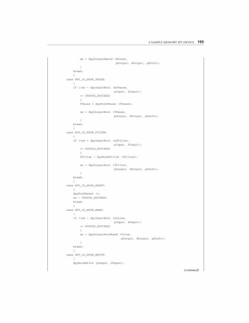
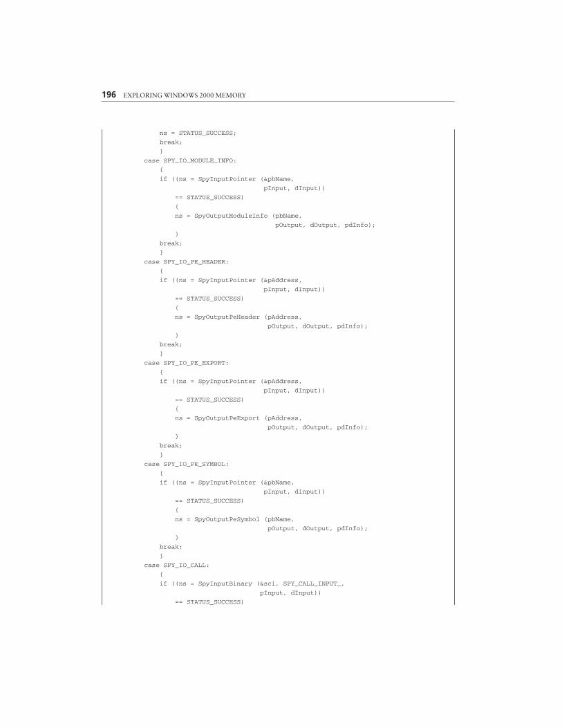
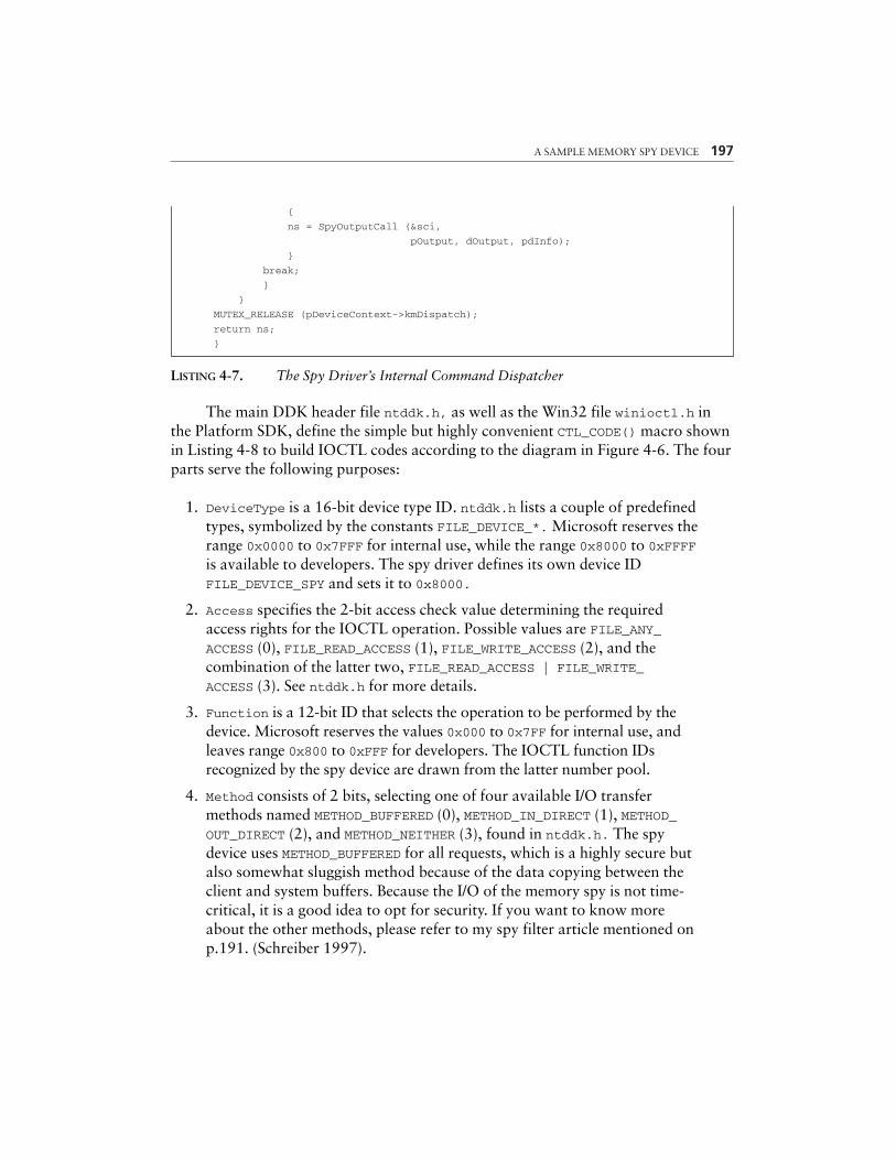
LISTING 4-7. The Spy Driver’s Internal Command Dispatcher
The main DDK header file ntddk.h, as well as the Win32 file winioctl.h inthe Platform SDK, define the simple but highly convenient CTL_CODE() macro shownin Listing 4-8 to build IOCTL codes according to the diagram in Figure 4-6. The fourparts serve the following purposes:
1. DeviceType is a 16-bit device type ID. ntddk.h lists a couple of predefinedtypes, symbolized by the constants FILE_DEVICE_*. Microsoft reserves therange 0x0000 to 0x7FFF for internal use, while the range 0x8000 to 0xFFFFis available to developers. The spy driver defines its own device IDFILE_DEVICE_SPY and sets it to 0x8000.
2. Access specifies the 2-bit access check value determining the requiredaccess rights for the IOCTL operation. Possible values are FILE_ANY_ACCESS (0), FILE_READ_ACCESS (1), FILE_WRITE_ACCESS (2), and thecombination of the latter two, FILE_READ_ACCESS | FILE_WRITE_ACCESS (3). See ntddk.h for more details.
3. Function is a 12-bit ID that selects the operation to be performed by thedevice. Microsoft reserves the values 0x000 to 0x7FF for internal use, andleaves range 0x800 to 0xFFF for developers. The IOCTL function IDsrecognized by the spy device are drawn from the latter number pool.
4. Method consists of 2 bits, selecting one of four available I/O transfermethods named METHOD_BUFFERED (0), METHOD_IN_DIRECT (1), METHOD_OUT_DIRECT (2), and METHOD_NEITHER (3), found in ntddk.h. The spydevice uses METHOD_BUFFERED for all requests, which is a highly secure butalso somewhat sluggish method because of the data copying between theclient and system buffers. Because the I/O of the memory spy is not time-critical, it is a good idea to opt for security. If you want to know moreabout the other methods, please refer to my spy filter article mentioned onp.191. (Schreiber 1997).
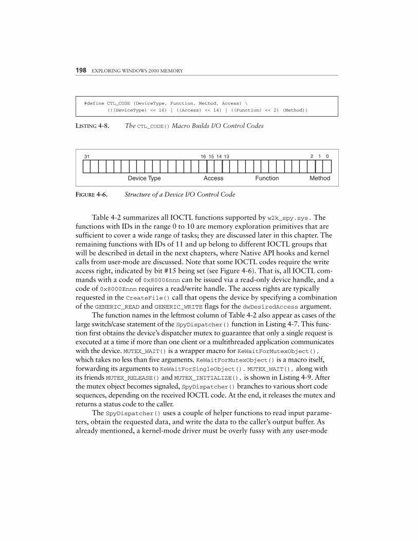
LISTING 4-8. The CTL_CODE() Macro Builds I/O Control Codes
198 EXPLORING WINDOWS 2000 MEMORY
16 15 14 13 2 1 0
Device Type Access Function Method
31
#define CTL_CODE (DeviceType, Function, Method, Access) \
(((DeviceType) << 16) | ((Access) << 14) | ((Function) << 2) (Method))
FIGURE 4-6. Structure of a Device I/O Control Code
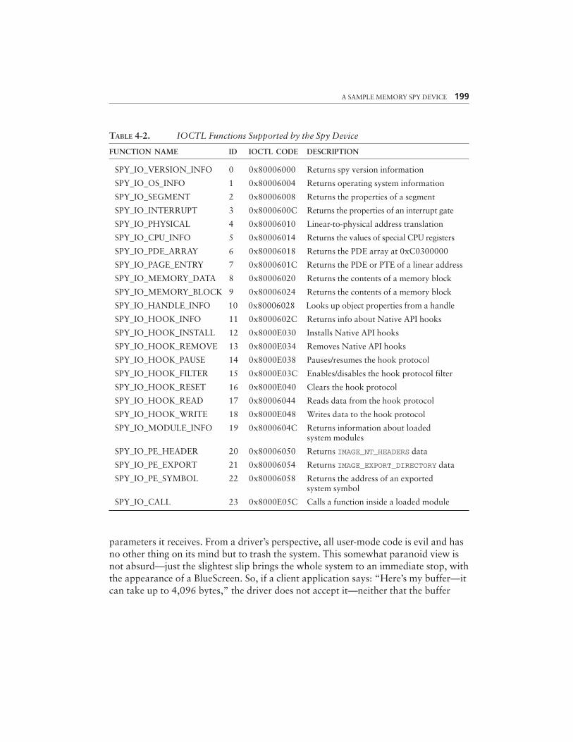
Table 4-2 summarizes all IOCTL functions supported by w2k_spy.sys. Thefunctions with IDs in the range 0 to 10 are memory exploration primitives that aresufficient to cover a wide range of tasks; they are discussed later in this chapter. Theremaining functions with IDs of 11 and up belong to different IOCTL groups thatwill be described in detail in the next chapters, where Native API hooks and kernelcalls from user-mode are discussed. Note that some IOCTL codes require the writeaccess right, indicated by bit #15 being set (see Figure 4-6). That is, all IOCTL com-mands with a code of 0x80006nnn can be issued via a read-only device handle, and acode of 0x8000Ennn requires a read/write handle. The access rights are typicallyrequested in the CreateFile() call that opens the device by specifying a combinationof the GENERIC_READ and GENERIC_WRITE flags for the dwDesiredAccess argument.
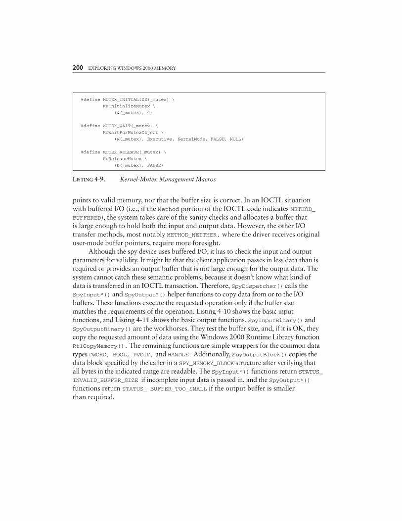
The function names in the leftmost column of Table 4-2 also appear as cases of thelarge switch/case statement of the SpyDispatcher() function in Listing 4-7. This func-tion first obtains the device’s dispatcher mutex to guarantee that only a single request isexecuted at a time if more than one client or a multithreaded application communicateswith the device. MUTEX_WAIT() is a wrapper macro for KeWaitForMutexObject(),which takes no less than five arguments. KeWaitForMutexObject() is a macro itself,forwarding its arguments to KeWaitForSingleObject(). MUTEX_WAIT(), along withits friends MUTEX_RELEASE() and MUTEX_INITIALIZE(), is shown in Listing 4-9. Afterthe mutex object becomes signaled, SpyDispatcher() branches to various short codesequences, depending on the received IOCTL code. At the end, it releases the mutex andreturns a status code to the caller.
The SpyDispatcher() uses a couple of helper functions to read input parame-ters, obtain the requested data, and write the data to the caller’s output buffer. Asalready mentioned, a kernel-mode driver must be overly fussy with any user-mode
A SAMPLE MEMORY SPY DEVICE 199
TABLE 4-2. IOCTL Functions Supported by the Spy Device
FUNCTION NAME ID IOCTL CODE DESCRIPTION
SPY_IO_VERSION_INFO 0 0x80006000 Returns spy version information
SPY_IO_OS_INFO 1 0x80006004 Returns operating system information
SPY_IO_SEGMENT 2 0x80006008 Returns the properties of a segment
SPY_IO_INTERRUPT 3 0x8000600C Returns the properties of an interrupt gate
SPY_IO_PHYSICAL 4 0x80006010 Linear-to-physical address translation
SPY_IO_CPU_INFO 5 0x80006014 Returns the values of special CPU registers
SPY_IO_PDE_ARRAY 6 0x80006018 Returns the PDE array at 0xC0300000
SPY_IO_PAGE_ENTRY 7 0x8000601C Returns the PDE or PTE of a linear address
SPY_IO_MEMORY_DATA 8 0x80006020 Returns the contents of a memory block
SPY_IO_MEMORY_BLOCK 9 0x80006024 Returns the contents of a memory block
SPY_IO_HANDLE_INFO 10 0x80006028 Looks up object properties from a handle
SPY_IO_HOOK_INFO 11 0x8000602C Returns info about Native API hooks
SPY_IO_HOOK_INSTALL 12 0x8000E030 Installs Native API hooks
SPY_IO_HOOK_REMOVE 13 0x8000E034 Removes Native API hooks
SPY_IO_HOOK_PAUSE 14 0x8000E038 Pauses/resumes the hook protocol
SPY_IO_HOOK_FILTER 15 0x8000E03C Enables/disables the hook protocol filter
SPY_IO_HOOK_RESET 16 0x8000E040 Clears the hook protocol
SPY_IO_HOOK_READ 17 0x80006044 Reads data from the hook protocol
SPY_IO_HOOK_WRITE 18 0x8000E048 Writes data to the hook protocol
SPY_IO_MODULE_INFO 19 0x8000604C Returns information about loaded system modules
SPY_IO_PE_HEADER 20 0x80006050 Returns IMAGE_NT_HEADERS data
SPY_IO_PE_EXPORT 21 0x80006054 Returns IMAGE_EXPORT_DIRECTORY data
SPY_IO_PE_SYMBOL 22 0x80006058 Returns the address of an exported system symbol
SPY_IO_CALL 23 0x8000E05C Calls a function inside a loaded module
parameters it receives. From a driver’s perspective, all user-mode code is evil and hasno other thing on its mind but to trash the system. This somewhat paranoid view isnot absurd—just the slightest slip brings the whole system to an immediate stop, withthe appearance of a BlueScreen. So, if a client application says: “Here’s my buffer—itcan take up to 4,096 bytes,” the driver does not accept it—neither that the buffer
200 EXPLORING WINDOWS 2000 MEMORY
#define MUTEX_INITIALIZE(_mutex) \
KeInitializeMutex \
(&(_mutex), 0)
#define MUTEX_WAIT(_mutex) \
KeWaitForMutexObject \
(&(_mutex), Executive, KernelMode, FALSE, NULL)
#define MUTEX_RELEASE(_mutex) \
KeReleaseMutex \
(&(_mutex), FALSE)
LISTING 4-9. Kernel-Mutex Management Macros
points to valid memory, nor that the buffer size is correct. In an IOCTL situationwith buffered I/O (i.e., if the Method portion of the IOCTL code indicates METHOD_BUFFERED), the system takes care of the sanity checks and allocates a buffer thatis large enough to hold both the input and output data. However, the other I/Otransfer methods, most notably METHOD_NEITHER, where the driver receives originaluser-mode buffer pointers, require more foresight.
Although the spy device uses buffered I/O, it has to check the input and outputparameters for validity. It might be that the client application passes in less data than isrequired or provides an output buffer that is not large enough for the output data. Thesystem cannot catch these semantic problems, because it doesn’t know what kind ofdata is transferred in an IOCTL transaction. Therefore, SpyDispatcher() calls theSpyInput*() and SpyOutput*() helper functions to copy data from or to the I/Obuffers. These functions execute the requested operation only if the buffer sizematches the requirements of the operation. Listing 4-10 shows the basic inputfunctions, and Listing 4-11 shows the basic output functions. SpyInputBinary() andSpyOutputBinary() are the workhorses. They test the buffer size, and, if it is OK, theycopy the requested amount of data using the Windows 2000 Runtime Library functionRtlCopyMemory(). The remaining functions are simple wrappers for the common datatypes DWORD, BOOL, PVOID, and HANDLE. Additionally, SpyOutputBlock() copies thedata block specified by the caller in a SPY_MEMORY_BLOCK structure after verifying thatall bytes in the indicated range are readable. The SpyInput*() functions return STATUS_INVALID_BUFFER_SIZE if incomplete input data is passed in, and the SpyOutput*()functions return STATUS_ BUFFER_TOO_SMALL if the output buffer is smallerthan required.
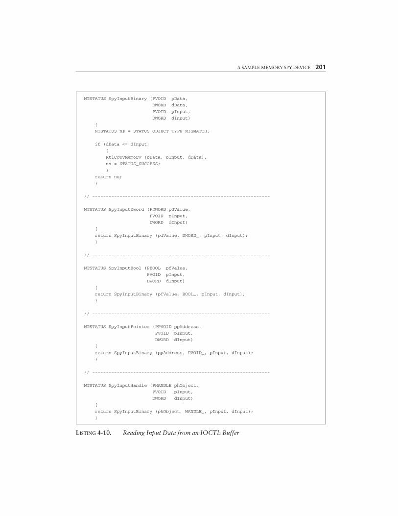
A SAMPLE MEMORY SPY DEVICE 201
NTSTATUS SpyInputBinary (PVOID pData,
DWORD dData,
PVOID pInput,
DWORD dInput)
{
NTSTATUS ns = STATUS_OBJECT_TYPE_MISMATCH;
if (dData <= dInput)
{
RtlCopyMemory (pData, pInput, dData);
ns = STATUS_SUCCESS;
}
return ns;
}
// -----------------------------------------------------------------
NTSTATUS SpyInputDword (PDWORD pdValue,
PVOID pInput,
DWORD dInput)
{
return SpyInputBinary (pdValue, DWORD_, pInput, dInput);
}
// -----------------------------------------------------------------
NTSTATUS SpyInputBool (PBOOL pfValue,
PVOID pInput,
DWORD dInput)
{
return SpyInputBinary (pfValue, BOOL_, pInput, dInput);
}
// -----------------------------------------------------------------
NTSTATUS SpyInputPointer (PPVOID ppAddress,
PVOID pInput,
DWORD dInput)
{
return SpyInputBinary (ppAddress, PVOID_, pInput, dInput);
}
// -----------------------------------------------------------------
NTSTATUS SpyInputHandle (PHANDLE phObject,
PVOID pInput,
DWORD dInput)
{
return SpyInputBinary (phObject, HANDLE_, pInput, dInput);
}
LISTING 4-10. Reading Input Data from an IOCTL Buffer
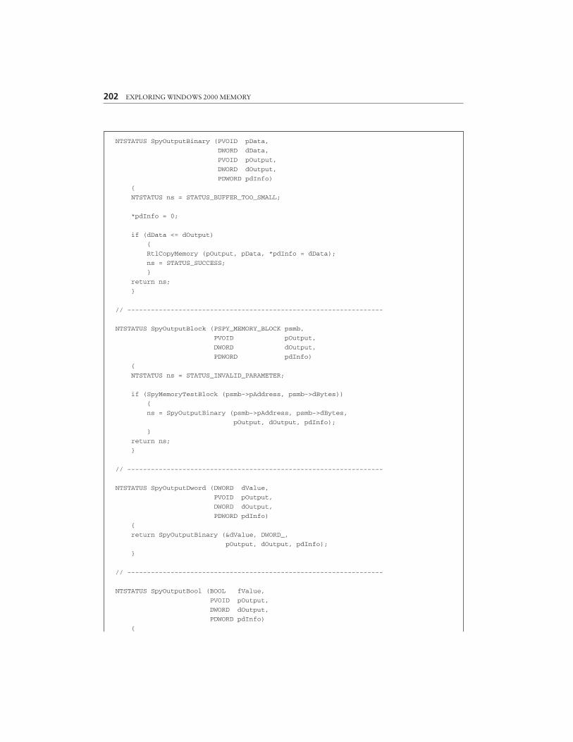
202 EXPLORING WINDOWS 2000 MEMORY
NTSTATUS SpyOutputBinary (PVOID pData,
DWORD dData,
PVOID pOutput,
DWORD dOutput,
PDWORD pdInfo)
{
NTSTATUS ns = STATUS_BUFFER_TOO_SMALL;
*pdInfo = 0;
if (dData <= dOutput)
{
RtlCopyMemory (pOutput, pData, *pdInfo = dData);
ns = STATUS_SUCCESS;
}
return ns;
}
// -----------------------------------------------------------------
NTSTATUS SpyOutputBlock (PSPY_MEMORY_BLOCK psmb,
PVOID pOutput,
DWORD dOutput,
PDWORD pdInfo)
{
NTSTATUS ns = STATUS_INVALID_PARAMETER;
if (SpyMemoryTestBlock (psmb->pAddress, psmb->dBytes))
{
ns = SpyOutputBinary (psmb->pAddress, psmb->dBytes,
pOutput, dOutput, pdInfo);
}
return ns;
}
// -----------------------------------------------------------------
NTSTATUS SpyOutputDword (DWORD dValue,
PVOID pOutput,
DWORD dOutput,
PDWORD pdInfo)
{
return SpyOutputBinary (&dValue, DWORD_,
pOutput, dOutput, pdInfo);
}
// -----------------------------------------------------------------
NTSTATUS SpyOutputBool (BOOL fValue,
PVOID pOutput,
DWORD dOutput,
PDWORD pdInfo)
{
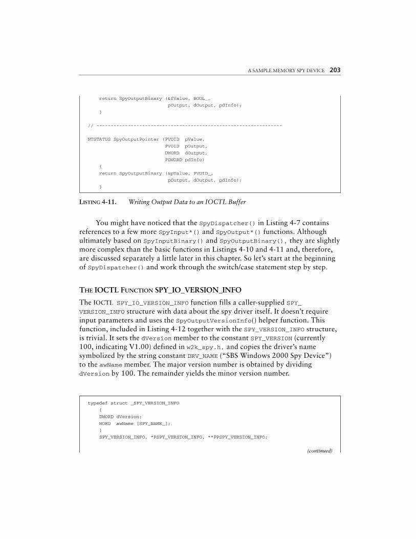
A SAMPLE MEMORY SPY DEVICE 203
return SpyOutputBinary (&fValue, BOOL_,
pOutput, dOutput, pdInfo);
}
// -----------------------------------------------------------------
NTSTATUS SpyOutputPointer (PVOID pValue,
PVOID pOutput,
DWORD dOutput,
PDWORD pdInfo)
{
return SpyOutputBinary (&pValue, PVOID_,
pOutput, dOutput, pdInfo);
}
LISTING 4-11. Writing Output Data to an IOCTL Buffer
You might have noticed that the SpyDispatcher() in Listing 4-7 containsreferences to a few more SpyInput*() and SpyOutput*() functions. Althoughultimately based on SpyInputBinary() and SpyOutputBinary(), they are slightlymore complex than the basic functions in Listings 4-10 and 4-11 and, therefore,are discussed separately a little later in this chapter. So let’s start at the beginningof SpyDispatcher() and work through the switch/case statement step by step.
THE IOCTL FUNCTION SPY_IO_VERSION_INFO
The IOCTL SPY_IO_VERSION_INFO function fills a caller-supplied SPY_VERSION_INFO structure with data about the spy driver itself. It doesn’t requireinput parameters and uses the SpyOutputVersionInfo() helper function. Thisfunction, included in Listing 4-12 together with the SPY_VERSION_INFO structure,is trivial. It sets the dVersion member to the constant SPY_VERSION (currently100, indicating V1.00) defined in w2k_spy.h, and copies the driver’s namesymbolized by the string constant DRV_NAME (“SBS Windows 2000 Spy Device”)to the awName member. The major version number is obtained by dividingdVersion by 100. The remainder yields the minor version number.
typedef struct _SPY_VERSION_INFO
{
DWORD dVersion;
WORD awName [SPY_NAME_];
}
SPY_VERSION_INFO, *PSPY_VERSION_INFO, **PPSPY_VERSION_INFO;
(continued)
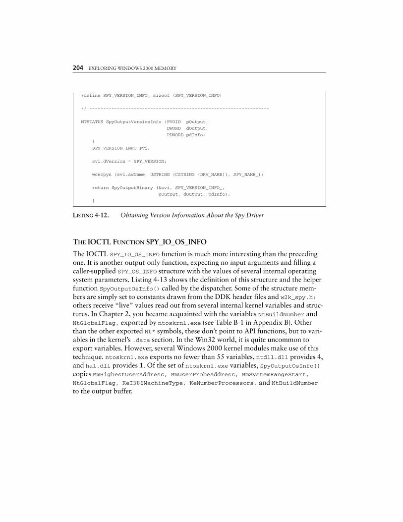
204 EXPLORING WINDOWS 2000 MEMORY
#define SPY_VERSION_INFO_ sizeof (SPY_VERSION_INFO)
// -----------------------------------------------------------------
NTSTATUS SpyOutputVersionInfo (PVOID pOutput,
DWORD dOutput,
PDWORD pdInfo)
{
SPY_VERSION_INFO svi;
svi.dVersion = SPY_VERSION;
wcscpyn (svi.awName, USTRING (CSTRING (DRV_NAME)), SPY_NAME_);
return SpyOutputBinary (&svi, SPY_VERSION_INFO_,
pOutput, dOutput, pdInfo);
}
LISTING 4-12. Obtaining Version Information About the Spy Driver
THE IOCTL FUNCTION SPY_IO_OS_INFO
The IOCTL SPY_IO_OS_INFO function is much more interesting than the precedingone. It is another output-only function, expecting no input arguments and filling acaller-supplied SPY_OS_INFO structure with the values of several internal operatingsystem parameters. Listing 4-13 shows the definition of this structure and the helperfunction SpyOutputOsInfo() called by the dispatcher. Some of the structure mem-bers are simply set to constants drawn from the DDK header files and w2k_spy.h;others receive “live” values read out from several internal kernel variables and struc-tures. In Chapter 2, you became acquainted with the variables NtBuildNumber andNtGlobalFlag, exported by ntoskrnl.exe (see Table B-1 in Appendix B). Otherthan the other exported Nt* symbols, these don’t point to API functions, but to vari-ables in the kernel’s .data section. In the Win32 world, it is quite uncommon toexport variables. However, several Windows 2000 kernel modules make use of thistechnique. ntoskrnl.exe exports no fewer than 55 variables, ntdll.dll provides 4,and hal.dll provides 1. Of the set of ntoskrnl.exe variables, SpyOutputOsInfo()copies MmHighestUserAddress, MmUserProbeAddress, MmSystemRangeStart,NtGlobalFlag, KeI386MachineType, KeNumberProcessors, and NtBuildNumberto the output buffer.
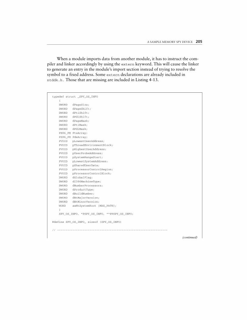
A SAMPLE MEMORY SPY DEVICE 205
typedef struct _SPY_OS_INFO
{
DWORD dPageSize;
DWORD dPageShift;
DWORD dPtiShift;
DWORD dPdiShift;
DWORD dPageMask;
DWORD dPtiMask;
DWORD dPdiMask;
PX86_PE PteArray;
PX86_PE PdeArray;
PVOID pLowestUserAddress;
PVOID pThreadEnvironmentBlock;
PVOID pHighestUserAddress;
PVOID pUserProbeAddress;
PVOID pSystemRangeStart;
PVOID pLowestSystemAddress;
PVOID pSharedUserData;
PVOID pProcessorControlRegion;
PVOID pProcessorControlBlock;
DWORD dGlobalFlag;
DWORD dI386MachineType;
DWORD dNumberProcessors;
DWORD dProductType;
DWORD dBuildNumber;
DWORD dNtMajorVersion;
DWORD dNtMinorVersion;
WORD awNtSystemRoot [MAX_PATH];
}
SPY_OS_INFO, *PSPY_OS_INFO, **PPSPY_OS_INFO;
#define SPY_OS_INFO_ sizeof (SPY_OS_INFO)
// -----------------------------------------------------------------
(continued)
When a module imports data from another module, it has to instruct the com-piler and linker accordingly by using the extern keyword. This will cause the linkerto generate an entry in the module’s import section instead of trying to resolve thesymbol to a fixed address. Some extern declarations are already included inntddk.h. Those that are missing are included in Listing 4-13.
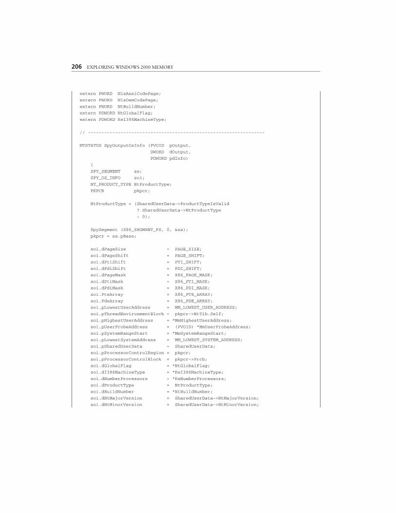
206 EXPLORING WINDOWS 2000 MEMORY
extern PWORD NlsAnsiCodePage;
extern PWORD NlsOemCodePage;
extern PWORD NtBuildNumber;
extern PDWORD NtGlobalFlag;
extern PDWORD KeI386MachineType;
// -----------------------------------------------------------------
NTSTATUS SpyOutputOsInfo (PVOID pOutput,
DWORD dOutput,
PDWORD pdInfo)
{
SPY_SEGMENT ss;
SPY_OS_INFO soi;
NT_PRODUCT_TYPE NtProductType;
PKPCR pkpcr;
NtProductType = (SharedUserData->ProductTypeIsValid
? SharedUserData->NtProductType
: 0);
SpySegment (X86_SEGMENT_FS, 0, &ss);
pkpcr = ss.pBase;
soi.dPageSize = PAGE_SIZE;
soi.dPageShift = PAGE_SHIFT;
soi.dPtiShift = PTI_SHIFT;
soi.dPdiShift = PDI_SHIFT;
soi.dPageMask = X86_PAGE_MASK;
soi.dPtiMask = X86_PTI_MASK;
soi.dPdiMask = X86_PDI_MASK;
soi.PteArray = X86_PTE_ARRAY;
soi.PdeArray = X86_PDE_ARRAY;
soi.pLowestUserAddress = MM_LOWEST_USER_ADDRESS;
soi.pThreadEnvironmentBlock = pkpcr->NtTib.Self;
soi.pHighestUserAddress = *MmHighestUserAddress;
soi.pUserProbeAddress = (PVOID) *MmUserProbeAddress;
soi.pSystemRangeStart = *MmSystemRangeStart;
soi.pLowestSystemAddress = MM_LOWEST_SYSTEM_ADDRESS;
soi.pSharedUserData = SharedUserData;
soi.pProcessorControlRegion = pkpcr;
soi.pProcessorControlBlock = pkpcr->Prcb;
soi.dGlobalFlag = *NtGlobalFlag;
soi.dI386MachineType = *KeI386MachineType;
soi.dNumberProcessors = *KeNumberProcessors;
soi.dProductType = NtProductType;
soi.dBuildNumber = *NtBuildNumber;
soi.dNtMajorVersion = SharedUserData->NtMajorVersion;
soi.dNtMinorVersion = SharedUserData->NtMinorVersion;
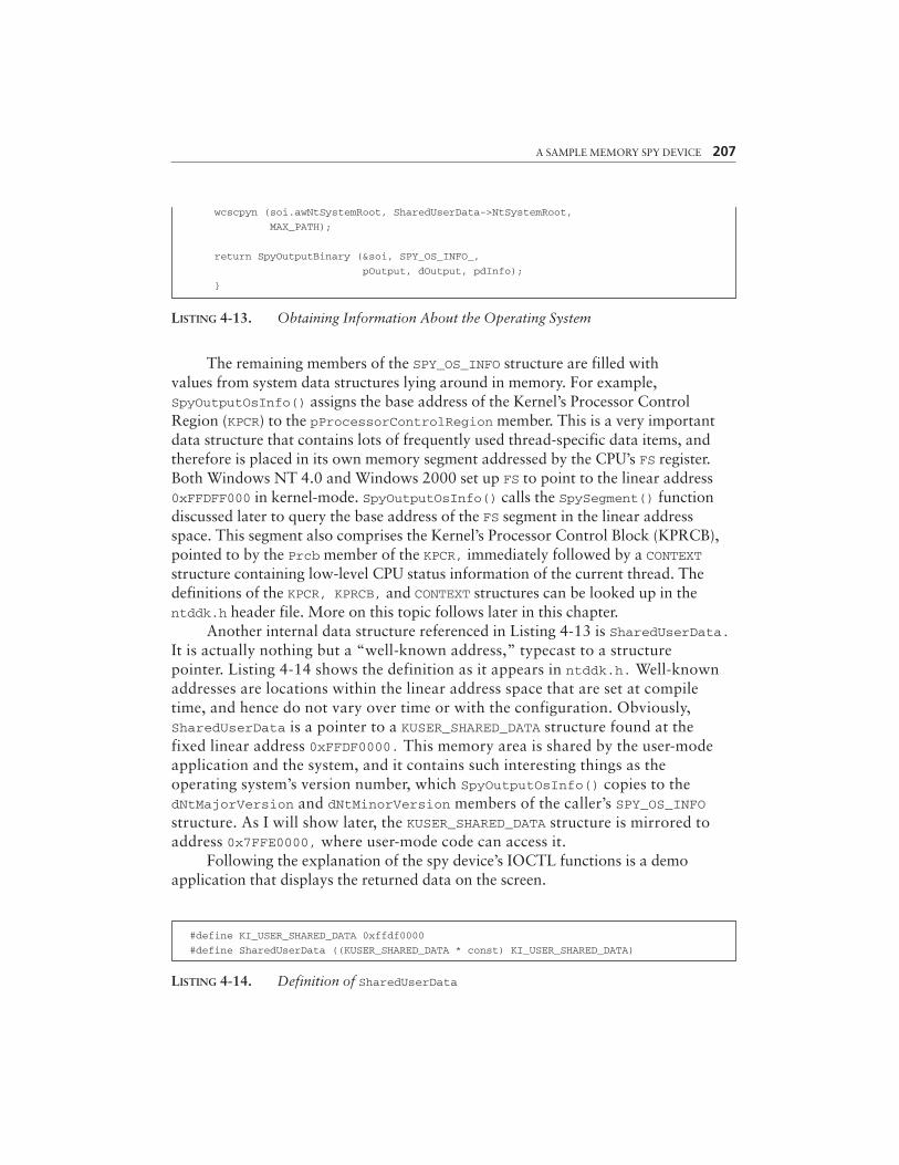
A SAMPLE MEMORY SPY DEVICE 207
LISTING 4-13. Obtaining Information About the Operating System
The remaining members of the SPY_OS_INFO structure are filled withvalues from system data structures lying around in memory. For example,SpyOutputOsInfo() assigns the base address of the Kernel’s Processor ControlRegion (KPCR) to the pProcessorControlRegion member. This is a very importantdata structure that contains lots of frequently used thread-specific data items, andtherefore is placed in its own memory segment addressed by the CPU’s FS register.Both Windows NT 4.0 and Windows 2000 set up FS to point to the linear address0xFFDFF000 in kernel-mode. SpyOutputOsInfo() calls the SpySegment() functiondiscussed later to query the base address of the FS segment in the linear addressspace. This segment also comprises the Kernel’s Processor Control Block (KPRCB),pointed to by the Prcb member of the KPCR, immediately followed by a CONTEXTstructure containing low-level CPU status information of the current thread. The definitions of the KPCR, KPRCB, and CONTEXT structures can be looked up in thentddk.h header file. More on this topic follows later in this chapter.
Another internal data structure referenced in Listing 4-13 is SharedUserData.It is actually nothing but a “well-known address,” typecast to a structure pointer. Listing 4-14 shows the definition as it appears in ntddk.h. Well-knownaddresses are locations within the linear address space that are set at compiletime, and hence do not vary over time or with the configuration. Obviously,SharedUserData is a pointer to a KUSER_SHARED_DATA structure found at the fixed linear address 0xFFDF0000. This memory area is shared by the user-modeapplication and the system, and it contains such interesting things as the operating system’s version number, which SpyOutputOsInfo() copies to the dNtMajorVersion and dNtMinorVersion members of the caller’s SPY_OS_INFOstructure. As I will show later, the KUSER_SHARED_DATA structure is mirrored toaddress 0x7FFE0000, where user-mode code can access it.
Following the explanation of the spy device’s IOCTL functions is a demo application that displays the returned data on the screen.
#define KI_USER_SHARED_DATA 0xffdf0000
#define SharedUserData ((KUSER_SHARED_DATA * const) KI_USER_SHARED_DATA)
LISTING 4-14. Definition of SharedUserData
wcscpyn (soi.awNtSystemRoot, SharedUserData->NtSystemRoot,
MAX_PATH);
return SpyOutputBinary (&soi, SPY_OS_INFO_,
pOutput, dOutput, pdInfo);
}
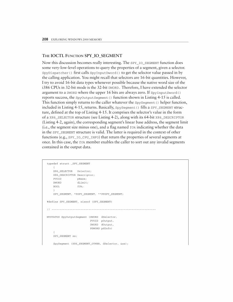
THE IOCTL FUNCTION SPY_IO_SEGMENT
Now this discussion becomes really interesting. The SPY_IO_SEGMENT function doessome very-low-level operations to query the properties of a segment, given a selector.SpyDispatcher() first calls SpyInputDword() to get the selector value passed in bythe calling application. You might recall that selectors are 16-bit quantities. However,I try to avoid 16-bit data types whenever possible because the native word size of thei386 CPUs in 32-bit mode is the 32-bit DWORD. Therefore, I have extended the selectorargument to a DWORD where the upper 16 bits are always zero. If SpyInputDword()reports success, the SpyOutputSegment() function shown in Listing 4-15 is called.This function simply returns to the caller whatever the SpySegment() helper function,included in Listing 4-15, returns. Basically, SpySegment() fills a SPY_SEGMENT struc-ture, defined at the top of Listing 4-15. It comprises the selector’s value in the formof a X86_SELECTOR structure (see Listing 4-2), along with its 64-bit X86_DESCRIPTOR(Listing 4-2, again), the corresponding segment’s linear base address, the segment limit(i.e., the segment size minus one), and a flag named fOk indicating whether the datain the SPY_SEGMENT structure is valid. The latter is required in the context of otherfunctions (e.g., SPY_IO_CPU_INFO) that return the properties of several segments atonce. In this case, the fOk member enables the caller to sort out any invalid segmentscontained in the output data.
208 EXPLORING WINDOWS 2000 MEMORY
typedef struct _SPY_SEGMENT
{
X86_SELECTOR Selector;
X86_DESCRIPTOR Descriptor;
PVOID pBase;
DWORD dLimit;
BOOL fOk;
}
SPY_SEGMENT, *PSPY_SEGMENT, **PPSPY_SEGMENT;
#define SPY_SEGMENT_ sizeof (SPY_SEGMENT)
// -----------------------------------------------------------------
NTSTATUS SpyOutputSegment (DWORD dSelector,
PVOID pOutput,
DWORD dOutput,
PDWORD pdInfo)
{
SPY_SEGMENT ss;
SpySegment (X86_SEGMENT_OTHER, dSelector, &ss);
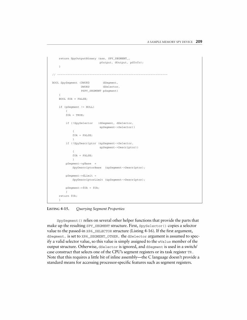
A SAMPLE MEMORY SPY DEVICE 209
return SpyOutputBinary (&ss, SPY_SEGMENT_,
pOutput, dOutput, pdInfo);
}
// -----------------------------------------------------------------
BOOL SpySegment (DWORD dSegment,
DWORD dSelector,
PSPY_SEGMENT pSegment)
{
BOOL fOk = FALSE;
if (pSegment != NULL)
{
fOk = TRUE;
if (!SpySelector (dSegment, dSelector,
&pSegment->Selector))
{
fOk = FALSE;
}
if (!SpyDescriptor (&pSegment->Selector,
&pSegment->Descriptor))
{
fOk = FALSE;
}
pSegment->pBase =
SpyDescriptorBase (&pSegment->Descriptor);
pSegment->dLimit =
SpyDescriptorLimit (&pSegment->Descriptor);
pSegment->fOk = fOk;
}
return fOk;
}
LISTING 4-15. Querying Segment Properties
SpySegment() relies on several other helper functions that provide the parts thatmake up the resulting SPY_SEGMENT structure. First, SpySelector() copies a selectorvalue to the passed-in X86_SELECTOR structure (Listing 4-16). If the first argument,dSegment, is set to X86_SEGMENT_OTHER, the dSelector argument is assumed to spec-ify a valid selector value, so this value is simply assigned to the wValue member of theoutput structure. Otherwise, dSelector is ignored, and dSegment is used in a switch/case construct that selects one of the CPU’s segment registers or its task register TR.Note that this requires a little bit of inline assembly—the C language doesn’t provide astandard means for accessing processor-specific features such as segment registers.

210 EXPLORING WINDOWS 2000 MEMORY
#define X86_SEGMENT_OTHER 0
#define X86_SEGMENT_CS 1
#define X86_SEGMENT_DS 2
#define X86_SEGMENT_ES 3
#define X86_SEGMENT_FS 4
#define X86_SEGMENT_GS 5
#define X86_SEGMENT_SS 6
#define X86_SEGMENT_TSS 7
// -----------------------------------------------------------------
BOOL SpySelector (DWORD dSegment,
DWORD dSelector,
PX86_SELECTOR pSelector)
{
X86_SELECTOR Selector = {0, 0};
BOOL fOk = FALSE;
if (pSelector != NULL)
{
fOk = TRUE;
switch (dSegment)
{
case X86_SEGMENT_OTHER:
{
if (fOk = ((dSelector >> X86_SELECTOR_SHIFT)
<= X86_SELECTOR_LIMIT))
{
Selector.wValue = (WORD) dSelector;
}
break;
}
case X86_SEGMENT_CS:
{
__asm mov Selector.wValue, cs
break;
}
case X86_SEGMENT_DS:
{
__asm mov Selector.wValue, ds
break;
}
case X86_SEGMENT_ES:
{
__asm mov Selector.wValue, es
break;
}
case X86_SEGMENT_FS:
{
__asm mov Selector.wValue, fs
break;
A SAMPLE MEMORY SPY DEVICE 211
}
case X86_SEGMENT_GS:
{
__asm mov Selector.wValue, gs
break;
}
case X86_SEGMENT_SS:
{
__asm mov Selector.wValue, ss
break;
}
case X86_SEGMENT_TSS:
{
__asm str Selector.wValue
break;
}
default:
{
fOk = FALSE;
break;
}
}
RtlCopyMemory (pSelector, &Selector, X86_SELECTOR_);
}
return fOk;
}
LISTING 4-16. Obtaining Selector Values
SpyDescriptor() reads in the 64-bit descriptor pointed to by the segment selec-tor (Listing 4-17). As you might recall, all selectors contain a Table Indicator (TI) bitthat decides whether the selector refers to a descriptor in the Global Descriptor Table(GDT, TI=0) or Local Descriptor Table (LDT, TI=1). The upper half of Listing 4-17handles the LDT case. First, the assembly language instructions SLDT and SGDT are usedto read the LDT selector value and the segment limit and base address of the GDT,respectively. Remember that the linear base address of the GDT is specified explicitly,whereas the LDT is referenced indirectly via a selector that points into the GDT. There-fore, SpyDescriptor() first validates the LDT selector value. If it is not the null seg-ment selector and does not point beyond the GDT limit, the SpyDescriptorType(),SpyDescriptorLimit(), and SpyDescriptorBase() functions attached to thebottom of Listing 4-17 are called to obtain the basic properties of the LDT:
• SpyDescriptorType() returns the values of a descriptor’s Type and S bit-fields (cf. Listing 4-2). The LDT selector must point to a system descriptorof type X86_DESCRIPTOR_SYS_LDT (2).
212 EXPLORING WINDOWS 2000 MEMORY
• SpyDescriptorLimit() compiles the segment limit from the Limit1 andLimit2 bit-fields of a descriptor. If its G flag indicates a granularity of4-KB, the value is shifted left by 12 bits, shifting in 1-bits from theright end.
• SpyDescriptorBase() simply arranges the Base1, Base2, and Base3bit-fields of a descriptor properly to yield a 32-bit linear address.
BOOL SpyDescriptor (PX86_SELECTOR pSelector,
PX86_DESCRIPTOR pDescriptor)
{
X86_SELECTOR ldt;
X86_TABLE gdt;
DWORD dType, dLimit;
BOOL fSystem;
PX86_DESCRIPTOR pDescriptors = NULL;
BOOL fOk = FALSE;
if (pDescriptor != NULL)
{
if (pSelector != NULL)
{
if (pSelector->TI) // ldt descriptor
{
__asm
{
sldt ldt.wValue
sgdt gdt.wLimit
}
if ((!ldt.TI) && ldt.Index &&
((ldt.wValue & X86_SELECTOR_INDEX)
<= gdt.wLimit))
{
dType = SpyDescriptorType (gdt.pDescriptors +
ldt.Index,
&fSystem);
dLimit = SpyDescriptorLimit (gdt.pDescriptors +
ldt.Index);
if ((dType == X86_DESCRIPTOR_SYS_LDT)
&&
((DWORD) (pSelector->wValue
& X86_SELECTOR_INDEX)
<= dLimit))
{
pDescriptors =
A SAMPLE MEMORY SPY DEVICE 213
SpyDescriptorBase (gdt.pDescriptors +
ldt.Index);
}
}
}
else // gdt descriptor
{
if (pSelector->Index)
{
__asm
{
sgdt gdt.wLimit
}
if ((pSelector->wValue & X86_SELECTOR_INDEX)
<= gdt.wLimit)
{
pDescriptors = gdt.pDescriptors;
}
}
}
}
if (pDescriptors != NULL)
{
RtlCopyMemory (pDescriptor,
pDescriptors + pSelector->Index,
X86_DESCRIPTOR_);
fOk = TRUE;
}
else
{
RtlZeroMemory (pDescriptor,
X86_DESCRIPTOR_);
}
}
return fOk;
}
// -----------------------------------------------------------------
PVOID SpyDescriptorBase (PX86_DESCRIPTOR pDescriptor)
{
return (PVOID) ((pDescriptor->Base1 ) |
(pDescriptor->Base2 << 16) |
(pDescriptor->Base3 << 24));
}
// -----------------------------------------------------------------
DWORD SpyDescriptorLimit (PX86_DESCRIPTOR pDescriptor)
{
return (pDescriptor->G ? (pDescriptor->Limit1 << 12) |
(pDescriptor->Limit2 << 28) | 0xFFF
(continued)
214 EXPLORING WINDOWS 2000 MEMORY
: (pDescriptor->Limit1 ) |
(pDescriptor->Limit2 << 16));
}
// -----------------------------------------------------------------
DWORD SpyDescriptorType (PX86_DESCRIPTOR pDescriptor,
PBOOL pfSystem)
{
if (pfSystem != NULL) *pfSystem = !pDescriptor->S;
return pDescriptor->Type;
}
LISTING 4-17. Obtaining Descriptor Values
If the selector’s TI bit indicates a GDT descriptor, things are much simpler.Again, the SGDT instruction is used to get the size and location of the GDT in linearmemory, and if the descriptor index specified by the selector is within the properrange, the pDescriptors variable is set to point to the GDT base address. In both theLDT and GDT cases, the pDescriptor variable is non-NULL if the caller has passedin a valid selector. In this case, the 64-bit descriptor value is copied to the caller’sX86_DESCRIPTOR structure. Otherwise, all members of this structure are set to zerowith the kind help of RtlZeroMemory().
We are still in the discussion of the SpySegment() function shown inListing 4-15. The SpySelector() and SpyDescriptor() calls have been handled.Only the concluding SpyDescriptorBase() and SpyDescriptorLimit() invoca-tions are left, but you already know what these functions do (see Listing 4-17). IfSpySelector() and SpyDescriptor() succeed, the data returned in the SPY_SEGMENT structure is valid. SpyDescriptorBase() and SpyDescriptorLimit()don’t return error flags because they cannot fail—they just might return meaning-less data if the supplied descriptor is invalid.
THE IOCTL FUNCTION SPY_IO_INTERRUPT
SPY_IO_INTERRUPT is similar to SPY_IO_SEGMENT, except that this function works oninterrupt descriptors stored in the system’s Interrupt Descriptor Table (IDT), ratherthan on LDT or GDT descriptors. The IDT contains up to 256 descriptors that can rep-resent task, interrupt, or trap gates (cf. Intel 1999c, pp. 5-11ff). By the way, interruptsand traps are quite similar in nature, differing in a tiny detail only: An interrupt handleris always entered with interrupts disabled, whereas the interrupt flag is left unchangedupon entering a trap handler. The SPY_IO_INTERRUPT caller supplies an interrupt num-ber between 0 and 256 in its input buffer and a SPY_INTERRUPT structure as outputbuffer, which will contain the properties of the corresponding interrupt handler on suc-
A SAMPLE MEMORY SPY DEVICE 215
cessful return. The SpyOutputInterrupt() helper function invoked by the dispatcher isa simple wrapper that calls SpyInterrupt() and copies the returned data to the outputbuffer. Both functions, as well as the SPY_INTERRUPT structure they operate on, areshown in Listing 4-18. The latter is filled by SpyInterrupt() with the following items:
• Selector specifies the selector of a Task-State Segment (TSS, see Intel1999c, pp. 6-4ff) or a code segment. A code segment selector determinesthe segment where an interrupt or trap handler is located.
• Gate is the 64-bit task, interrupt, or trap gate descriptor addressed bythe selector.
• Segment contains the properties of the segment addressed by the gate.
• pOffset specifies the offset of the interrupt or trap handler’s entry pointrelative to the base address of the surrounding code segment. Because taskgates don’t comprise an offset value, this member must be ignored if theinput selector refers to a TSS.
• fOk is a flag that indicates whether the data in the SPY_INTERRUPTstructure is valid.
A TSS is typically used to guarantee that an error situation is handled by avalid task. It is a special system segment type that holds 104 bytes of processor stateinformation needed to restore a task after a task switch has occurred, as outlined inTable 4-3. The CPU always forces a task switch and saves all CPU registers to theTSS when an interrupt associated with a TSS occurs. Windows 2000 stores task gatesin the interrupt slots 0x02 (Nonmaskable Interrupt [NMI]), 0x08 (Double Fault), and0x12 (Stack-Segment Fault). The remaining entries point to interrupt handlers. Unusedinterrupts are handled by dummy routines named KiUnexpectedInterruptNNN(),where “NNN” is a decimal ordinal number. These handlers branch to the internalfunction KiEndUnexpectedRange(), which in turn branches to KiUnexpectedInterruptTail(), passing in the number of the unhandled interrupt.
typedef struct _SPY_INTERRUPT
{
X86_SELECTOR Selector;
X86_GATE Gate;
SPY_SEGMENT Segment;
PVOID pOffset;
BOOL fOk;
}
SPY_INTERRUPT, *PSPY_INTERRUPT, **PPSPY_INTERRUPT;
(continued)
216 EXPLORING WINDOWS 2000 MEMORY
#define SPY_INTERRUPT_ sizeof (SPY_INTERRUPT)
// -----------------------------------------------------------------
NTSTATUS SpyOutputInterrupt (DWORD dInterrupt,
PVOID pOutput,
DWORD dOutput,
PDWORD pdInfo)
{
SPY_INTERRUPT si;
SpyInterrupt (dInterrupt, &si);
return SpyOutputBinary (&si, SPY_INTERRUPT_,
pOutput, dOutput, pdInfo);
}
// -----------------------------------------------------------------
BOOL SpyInterrupt (DWORD dInterrupt,
PSPY_INTERRUPT pInterrupt)
{
BOOL fOk = FALSE;
if (pInterrupt != NULL)
{
if (dInterrupt <= X86_SELECTOR_LIMIT)
{
fOk = TRUE;
if (!SpySelector (X86_SEGMENT_OTHER,
dInterrupt << X86_SELECTOR_SHIFT,
&pInterrupt->Selector))
{
fOk = FALSE;
}
if (!SpyIdtGate (&pInterrupt->Selector,
&pInterrupt->Gate))
{
fOk = FALSE;
}
if (!SpySegment (X86_SEGMENT_OTHER,
pInterrupt->Gate.Selector,
&pInterrupt->Segment))
{
fOk = FALSE;
}
pInterrupt->pOffset = SpyGateOffset (&pInterrupt->Gate);
}
else
{
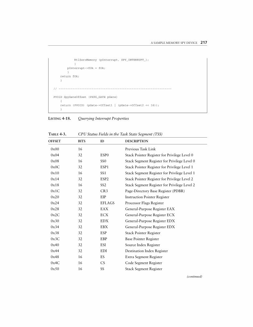
A SAMPLE MEMORY SPY DEVICE 217
RtlZeroMemory (pInterrupt, SPY_INTERRUPT_);
}
pInterrupt->fOk = fOk;
}
return fOk;
}
// -----------------------------------------------------------------
PVOID SpyGateOffset (PX86_GATE pGate)
{
return (PVOID) (pGate->Offset1 | (pGate->Offset2 << 16));
}
LISTING 4-18. Querying Interrupt Properties
TABLE 4-3. CPU Status Fields in the Task State Segment (TSS)
OFFSET BITS ID DESCRIPTION
0x00 16 Previous Task Link
0x04 32 ESP0 Stack Pointer Register for Privilege Level 0
0x08 16 SS0 Stack Segment Register for Privilege Level 0
0x0C 32 ESP1 Stack Pointer Register for Privilege Level 1
0x10 16 SS1 Stack Segment Register for Privilege Level 1
0x14 32 ESP2 Stack Pointer Register for Privilege Level 2
0x18 16 SS2 Stack Segment Register for Privilege Level 2
0x1C 32 CR3 Page-Directory Base Register (PDBR)
0x20 32 EIP Instruction Pointer Register
0x24 32 EFLAGS Processor Flags Register
0x28 32 EAX General-Purpose Register EAX
0x2C 32 ECX General-Purpose Register ECX
0x30 32 EDX General-Purpose Register EDX
0x34 32 EBX General-Purpose Register EDX
0x38 32 ESP Stack Pointer Register
0x3C 32 EBP Base Pointer Register
0x40 32 ESI Source Index Register
0x44 32 EDI Destination Index Register
0x48 16 ES Extra Segment Register
0x4C 16 CS Code Segment Register
0x50 16 SS Stack Segment Register
(continued)
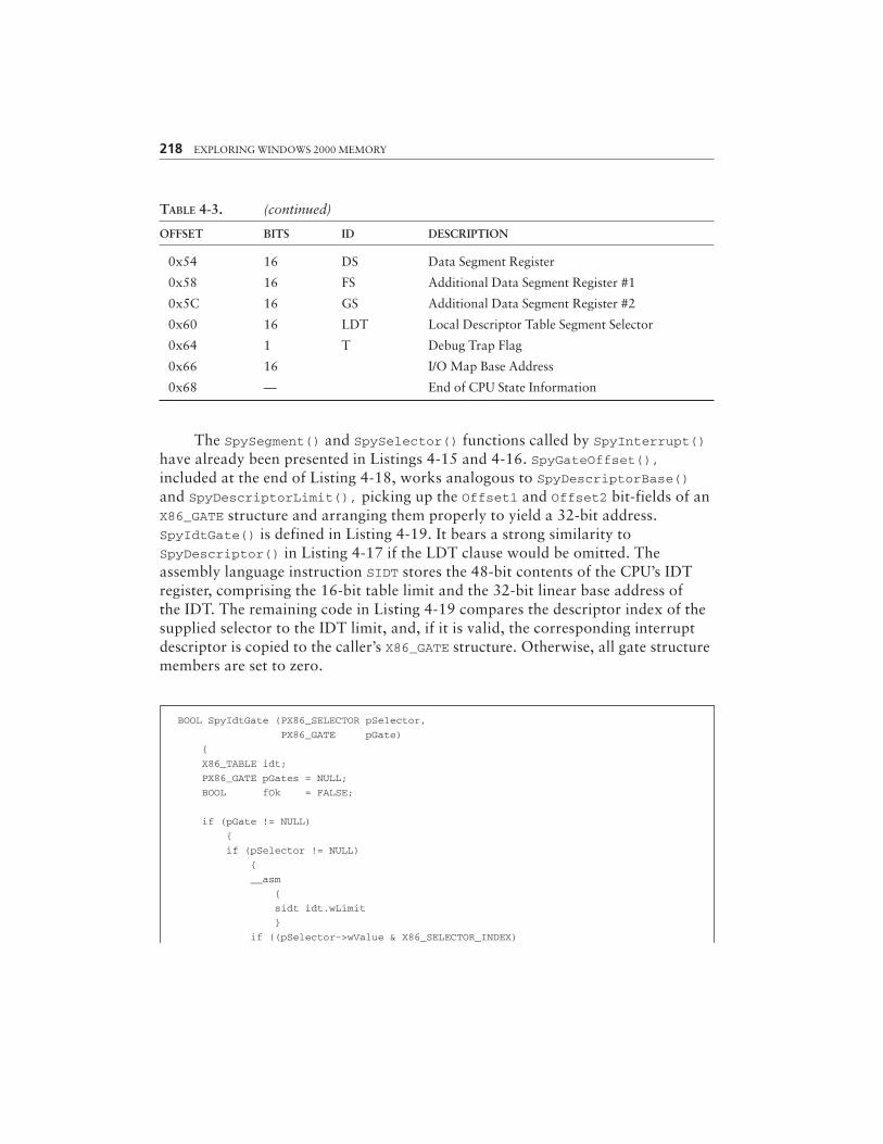
218 EXPLORING WINDOWS 2000 MEMORY
TABLE 4-3. (continued)
OFFSET BITS ID DESCRIPTION
0x54 16 DS Data Segment Register
0x58 16 FS Additional Data Segment Register #1
0x5C 16 GS Additional Data Segment Register #2
0x60 16 LDT Local Descriptor Table Segment Selector
0x64 1 T Debug Trap Flag
0x66 16 I/O Map Base Address
0x68 — End of CPU State Information
The SpySegment() and SpySelector() functions called by SpyInterrupt()have already been presented in Listings 4-15 and 4-16. SpyGateOffset(),included at the end of Listing 4-18, works analogous to SpyDescriptorBase()and SpyDescriptorLimit(), picking up the Offset1 and Offset2 bit-fields of anX86_GATE structure and arranging them properly to yield a 32-bit address.SpyIdtGate() is defined in Listing 4-19. It bears a strong similarity toSpyDescriptor() in Listing 4-17 if the LDT clause would be omitted. Theassembly language instruction SIDT stores the 48-bit contents of the CPU’s IDTregister, comprising the 16-bit table limit and the 32-bit linear base address ofthe IDT. The remaining code in Listing 4-19 compares the descriptor index of thesupplied selector to the IDT limit, and, if it is valid, the corresponding interruptdescriptor is copied to the caller’s X86_GATE structure. Otherwise, all gate structuremembers are set to zero.
BOOL SpyIdtGate (PX86_SELECTOR pSelector,
PX86_GATE pGate)
{
X86_TABLE idt;
PX86_GATE pGates = NULL;
BOOL fOk = FALSE;
if (pGate != NULL)
{
if (pSelector != NULL)
{
__asm
{
sidt idt.wLimit
}
if ((pSelector->wValue & X86_SELECTOR_INDEX)
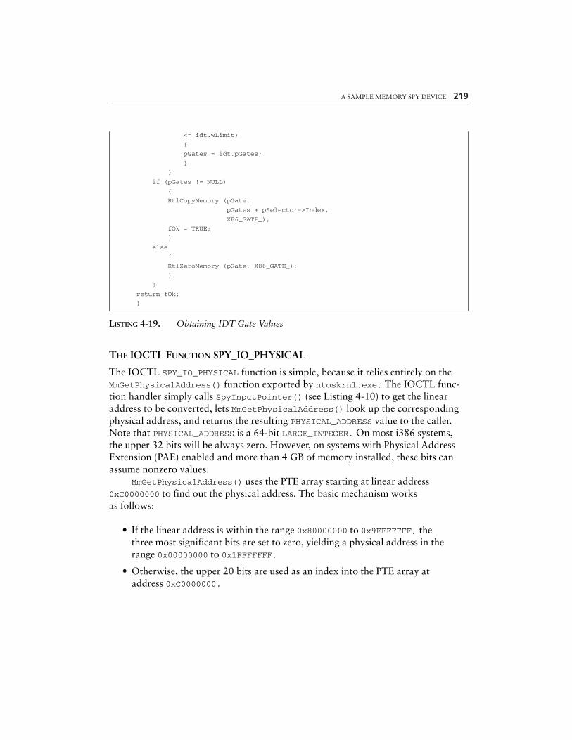
A SAMPLE MEMORY SPY DEVICE 219
<= idt.wLimit)
{
pGates = idt.pGates;
}
}
if (pGates != NULL)
{
RtlCopyMemory (pGate,
pGates + pSelector->Index,
X86_GATE_);
fOk = TRUE;
}
else
{
RtlZeroMemory (pGate, X86_GATE_);
}
}
return fOk;
}
LISTING 4-19. Obtaining IDT Gate Values
THE IOCTL FUNCTION SPY_IO_PHYSICAL
The IOCTL SPY_IO_PHYSICAL function is simple, because it relies entirely on theMmGetPhysicalAddress() function exported by ntoskrnl.exe. The IOCTL func-tion handler simply calls SpyInputPointer() (see Listing 4-10) to get the linearaddress to be converted, lets MmGetPhysicalAddress() look up the correspondingphysical address, and returns the resulting PHYSICAL_ADDRESS value to the caller.Note that PHYSICAL_ADDRESS is a 64-bit LARGE_INTEGER. On most i386 systems,the upper 32 bits will be always zero. However, on systems with Physical AddressExtension (PAE) enabled and more than 4 GB of memory installed, these bits canassume nonzero values.
MmGetPhysicalAddress() uses the PTE array starting at linear address0xC0000000 to find out the physical address. The basic mechanism worksas follows:
• If the linear address is within the range 0x80000000 to 0x9FFFFFFF, thethree most significant bits are set to zero, yielding a physical address in therange 0x00000000 to 0x1FFFFFFF.
• Otherwise, the upper 20 bits are used as an index into the PTE array ataddress 0xC0000000.

220 EXPLORING WINDOWS 2000 MEMORY
• If the P bit of the target PTE is set, indicating that the corresponding pageis present in physical memory, all PTE bits except for the 20-bit PFN arestripped, and the least significant 12 bits of the linear address are added,resulting in a proper 32-bit physical address.
• If the physical page is not present, MmGetPhysicalAddress() returns zero.
It is interesting to see that MmGetPhysicalAddress() assumes 4-KB pages for alllinear addresses outside the kernel memory range 0x80000000 to 0x9FFFFFFF. Otherfunctions, such as MmIsAddressValid(), first load the PDE of the linear address andcheck its PS bit to find out whether the page size is 4 KB or 4 MB. This is a muchmore general approach that can cope with arbitrary memory configurations. Bothfunctions return correct results, because Windows 2000 happens to use 4-MB pagesin the 0x80000000 to 0x9FFFFFFF memory area only. Some kernel API functions,however, are apparently designed to be more flexible than others.
THE IOCTL FUNCTION SPY_IO_CPU_INFO
Several CPU instructions are available only to code running on privilege level zero,which is the most privileged of the four available levels. In Windows 2000 terminol-ogy, this means kernel-mode. Among the forbidden instructions are those that readthe contents of the control registers CR0, CR2, and CR3. Because these registerscontain interesting information, an application might wish to find a way to accessthem, and the SPY_IO_CPU_INFO function is the solution. As Listing 4-20 shows, theSpyOutputCpuInfo() function invoked by the IOCTL handler uses some ASM inlinecode to read the control registers, along with other valuable information, such as thecontents of the IDT, GDT, and LDT registers and the segment selectors stored in theregisters CS, DS, ES, FS, GS, SS, and TR. The Task Register TR contains a selectorthat refers to the TSS of the current task.
typedef struct _SPY_CPU_INFO
{
X86_REGISTER cr0;
X86_REGISTER cr2;
X86_REGISTER cr3;
SPY_SEGMENT cs;
SPY_SEGMENT ds;
SPY_SEGMENT es;
SPY_SEGMENT fs;
SPY_SEGMENT gs;
SPY_SEGMENT ss;
SPY_SEGMENT tss;
X86_TABLE idt;
X86_TABLE gdt;
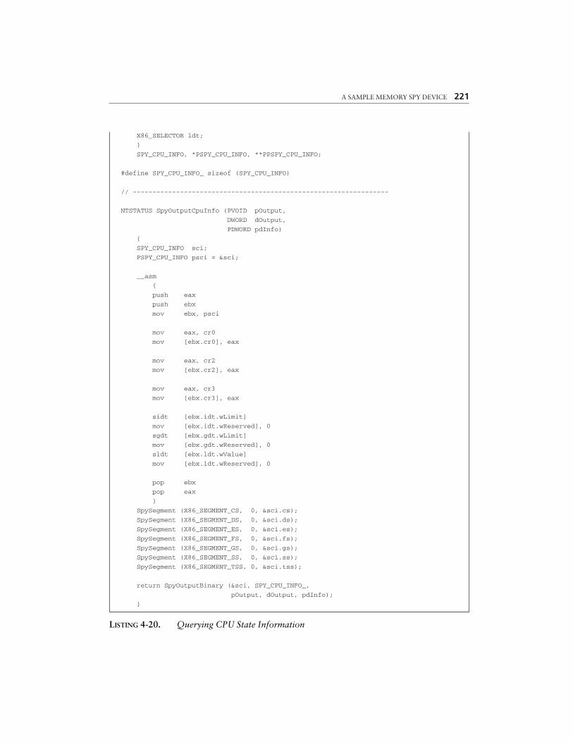
A SAMPLE MEMORY SPY DEVICE 221
X86_SELECTOR ldt;
}
SPY_CPU_INFO, *PSPY_CPU_INFO, **PPSPY_CPU_INFO;
#define SPY_CPU_INFO_ sizeof (SPY_CPU_INFO)
// -----------------------------------------------------------------
NTSTATUS SpyOutputCpuInfo (PVOID pOutput,
DWORD dOutput,
PDWORD pdInfo)
{
SPY_CPU_INFO sci;
PSPY_CPU_INFO psci = &sci;
__asm
{
push eax
push ebx
mov ebx, psci
mov eax, cr0
mov [ebx.cr0], eax
mov eax, cr2
mov [ebx.cr2], eax
mov eax, cr3
mov [ebx.cr3], eax
sidt [ebx.idt.wLimit]
mov [ebx.idt.wReserved], 0
sgdt [ebx.gdt.wLimit]
mov [ebx.gdt.wReserved], 0
sldt [ebx.ldt.wValue]
mov [ebx.ldt.wReserved], 0
pop ebx
pop eax
}
SpySegment (X86_SEGMENT_CS, 0, &sci.cs);
SpySegment (X86_SEGMENT_DS, 0, &sci.ds);
SpySegment (X86_SEGMENT_ES, 0, &sci.es);
SpySegment (X86_SEGMENT_FS, 0, &sci.fs);
SpySegment (X86_SEGMENT_GS, 0, &sci.gs);
SpySegment (X86_SEGMENT_SS, 0, &sci.ss);
SpySegment (X86_SEGMENT_TSS, 0, &sci.tss);
return SpyOutputBinary (&sci, SPY_CPU_INFO_,
pOutput, dOutput, pdInfo);
}
LISTING 4-20. Querying CPU State Information
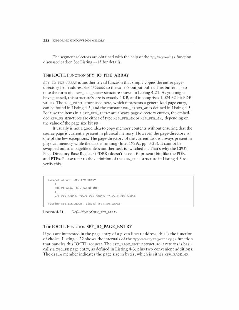
222 EXPLORING WINDOWS 2000 MEMORY
The segment selectors are obtained with the help of the SpySegment() functiondiscussed earlier. See Listing 4-15 for details.
THE IOCTL FUNCTION SPY_IO_PDE_ARRAY
SPY_IO_PDE_ARRAY is another trivial function that simply copies the entire page-directory from address 0xC0300000 to the caller’s output buffer. This buffer has totake the form of a SPY_PDE_ARRAY structure shown in Listing 4-21. As you mighthave guessed, this structure’s size is exactly 4 KB, and it comprises 1,024 32-bit PDEvalues. The X86_PE structure used here, which represents a generalized page entry,can be found in Listing 4-3, and the constant X86_PAGES_4M is defined in Listing 4-5.Because the items in a SPY_PDE_ARRAY are always page-directory entries, the embed-ded X86_PE structures are either of type X86_PDE_4M or X86_PDE_4K, depending onthe value of the page size bit PS.
It usually is not a good idea to copy memory contents without ensuring that thesource page is currently present in physical memory. However, the page-directory isone of the few exceptions. The page-directory of the current task is always present inphysical memory while the task is running (Intel 1999c, pp. 3-23). It cannot beswapped out to a pagefile unless another task is switched in. That’s why the CPU’sPage-Directory Base Register (PDBR) doesn’t have a P (present) bit, like the PDEsand PTEs. Please refer to the definition of the X86_PDBR structure in Listing 4-3 toverify this.
typedef struct _SPY_PDE_ARRAY
{
X86_PE apde [X86_PAGES_4M];
}
SPY_PDE_ARRAY, *PSPY_PDE_ARRAY, **PPSPY_PDE_ARRAY;
#define SPY_PDE_ARRAY_ sizeof (SPY_PDE_ARRAY)
LISTING 4-21. Definition of SPY_PDE_ARRAY
THE IOCTL FUNCTION SPY_IO_PAGE_ENTRY
If you are interested in the page entry of a given linear address, this is the functionof choice. Listing 4-22 shows the internals of the SpyMemoryPageEntry() functionthat handles this IOCTL request. The SPY_PAGE_ENTRY structure it returns is basi-cally a X86_PE page entry, as defined in Listing 4-3, plus two convenient additions:The dSize member indicates the page size in bytes, which is either X86_PAGE_4K
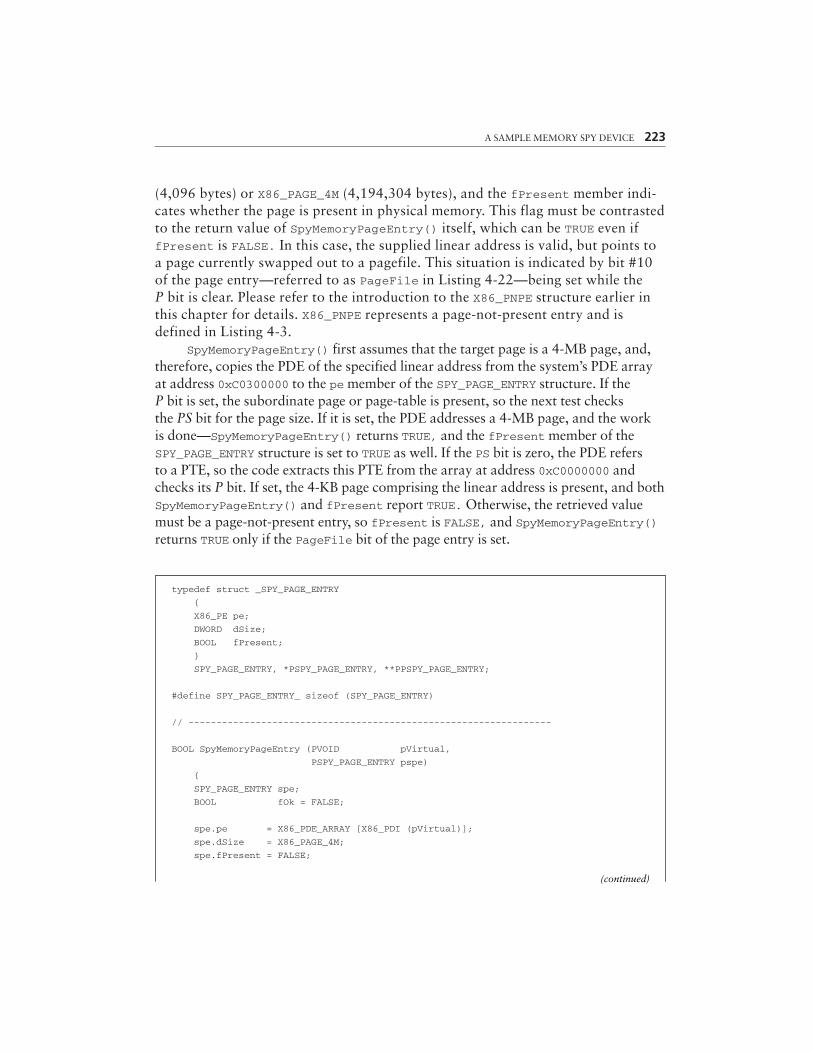
A SAMPLE MEMORY SPY DEVICE 223
(4,096 bytes) or X86_PAGE_4M (4,194,304 bytes), and the fPresent member indi-cates whether the page is present in physical memory. This flag must be contrastedto the return value of SpyMemoryPageEntry() itself, which can be TRUE even iffPresent is FALSE. In this case, the supplied linear address is valid, but points toa page currently swapped out to a pagefile. This situation is indicated by bit #10of the page entry—referred to as PageFile in Listing 4-22—being set while theP bit is clear. Please refer to the introduction to the X86_PNPE structure earlier inthis chapter for details. X86_PNPE represents a page-not-present entry and isdefined in Listing 4-3.
SpyMemoryPageEntry() first assumes that the target page is a 4-MB page, and,therefore, copies the PDE of the specified linear address from the system’s PDE arrayat address 0xC0300000 to the pe member of the SPY_PAGE_ENTRY structure. If theP bit is set, the subordinate page or page-table is present, so the next test checksthe PS bit for the page size. If it is set, the PDE addresses a 4-MB page, and the workis done—SpyMemoryPageEntry() returns TRUE, and the fPresent member of theSPY_PAGE_ENTRY structure is set to TRUE as well. If the PS bit is zero, the PDE refersto a PTE, so the code extracts this PTE from the array at address 0xC0000000 andchecks its P bit. If set, the 4-KB page comprising the linear address is present, and bothSpyMemoryPageEntry() and fPresent report TRUE. Otherwise, the retrieved valuemust be a page-not-present entry, so fPresent is FALSE, and SpyMemoryPageEntry()returns TRUE only if the PageFile bit of the page entry is set.
typedef struct _SPY_PAGE_ENTRY
{
X86_PE pe;
DWORD dSize;
BOOL fPresent;
}
SPY_PAGE_ENTRY, *PSPY_PAGE_ENTRY, **PPSPY_PAGE_ENTRY;
#define SPY_PAGE_ENTRY_ sizeof (SPY_PAGE_ENTRY)
// -----------------------------------------------------------------
BOOL SpyMemoryPageEntry (PVOID pVirtual,
PSPY_PAGE_ENTRY pspe)
{
SPY_PAGE_ENTRY spe;
BOOL fOk = FALSE;
spe.pe = X86_PDE_ARRAY [X86_PDI (pVirtual)];
spe.dSize = X86_PAGE_4M;
spe.fPresent = FALSE;
(continued)
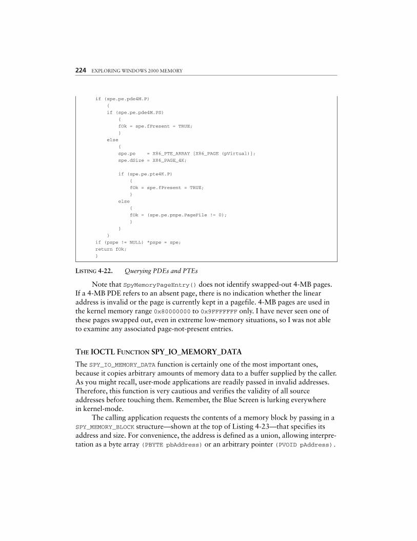
224 EXPLORING WINDOWS 2000 MEMORY
if (spe.pe.pde4M.P)
{
if (spe.pe.pde4M.PS)
{
fOk = spe.fPresent = TRUE;
}
else
{
spe.pe = X86_PTE_ARRAY [X86_PAGE (pVirtual)];
spe.dSize = X86_PAGE_4K;
if (spe.pe.pte4K.P)
{
fOk = spe.fPresent = TRUE;
}
else
{
fOk = (spe.pe.pnpe.PageFile != 0);
}
}
}
if (pspe != NULL) *pspe = spe;
return fOk;
}
LISTING 4-22. Querying PDEs and PTEs
Note that SpyMemoryPageEntry() does not identify swapped-out 4-MB pages.If a 4-MB PDE refers to an absent page, there is no indication whether the linearaddress is invalid or the page is currently kept in a pagefile. 4-MB pages are used inthe kernel memory range 0x80000000 to 0x9FFFFFFF only. I have never seen one ofthese pages swapped out, even in extreme low-memory situations, so I was not ableto examine any associated page-not-present entries.
THE IOCTL FUNCTION SPY_IO_MEMORY_DATA
The SPY_IO_MEMORY_DATA function is certainly one of the most important ones,because it copies arbitrary amounts of memory data to a buffer supplied by the caller.As you might recall, user-mode applications are readily passed in invalid addresses.Therefore, this function is very cautious and verifies the validity of all sourceaddresses before touching them. Remember, the Blue Screen is lurking everywherein kernel-mode.
The calling application requests the contents of a memory block by passing in aSPY_MEMORY_BLOCK structure—shown at the top of Listing 4-23—that specifies itsaddress and size. For convenience, the address is defined as a union, allowing interpre-tation as a byte array (PBYTE pbAddress) or an arbitrary pointer (PVOID pAddress).
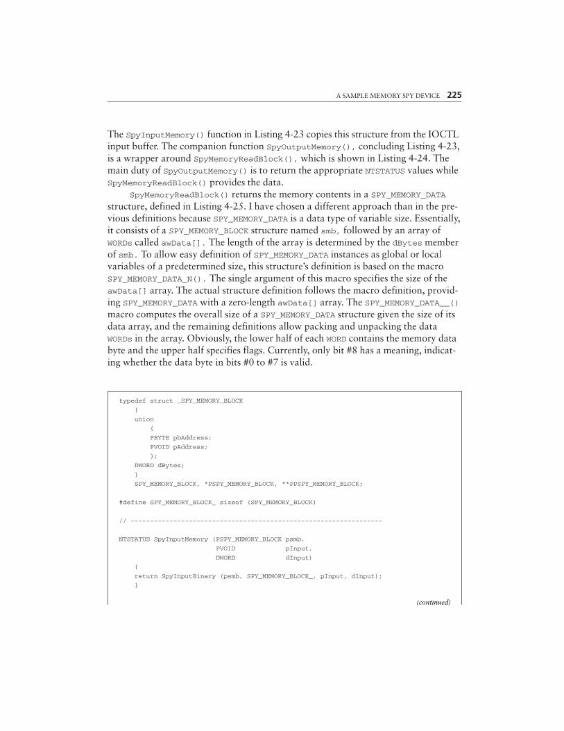
A SAMPLE MEMORY SPY DEVICE 225
typedef struct _SPY_MEMORY_BLOCK
{
union
{
PBYTE pbAddress;
PVOID pAddress;
};
DWORD dBytes;
}
SPY_MEMORY_BLOCK, *PSPY_MEMORY_BLOCK, **PPSPY_MEMORY_BLOCK;
#define SPY_MEMORY_BLOCK_ sizeof (SPY_MEMORY_BLOCK)
// -----------------------------------------------------------------
NTSTATUS SpyInputMemory (PSPY_MEMORY_BLOCK psmb,
PVOID pInput,
DWORD dInput)
{
return SpyInputBinary (psmb, SPY_MEMORY_BLOCK_, pInput, dInput);
}
The SpyInputMemory() function in Listing 4-23 copies this structure from the IOCTLinput buffer. The companion function SpyOutputMemory(), concluding Listing 4-23,is a wrapper around SpyMemoryReadBlock(), which is shown in Listing 4-24. Themain duty of SpyOutputMemory() is to return the appropriate NTSTATUS values whileSpyMemoryReadBlock() provides the data.
SpyMemoryReadBlock() returns the memory contents in a SPY_MEMORY_DATAstructure, defined in Listing 4-25. I have chosen a different approach than in the pre-vious definitions because SPY_MEMORY_DATA is a data type of variable size. Essentially,it consists of a SPY_MEMORY_BLOCK structure named smb, followed by an array ofWORDs called awData[]. The length of the array is determined by the dBytes memberof smb. To allow easy definition of SPY_MEMORY_DATA instances as global or localvariables of a predetermined size, this structure’s definition is based on the macroSPY_MEMORY_DATA_N(). The single argument of this macro specifies the size of theawData[] array. The actual structure definition follows the macro definition, provid-ing SPY_MEMORY_DATA with a zero-length awData[] array. The SPY_MEMORY_DATA__()macro computes the overall size of a SPY_MEMORY_DATA structure given the size of itsdata array, and the remaining definitions allow packing and unpacking the dataWORDs in the array. Obviously, the lower half of each WORD contains the memory databyte and the upper half specifies flags. Currently, only bit #8 has a meaning, indicat-ing whether the data byte in bits #0 to #7 is valid.
(continued)
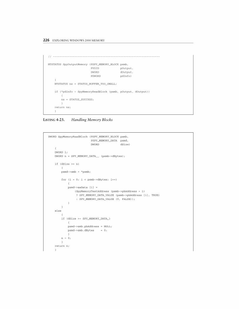
226 EXPLORING WINDOWS 2000 MEMORY
// -----------------------------------------------------------------
NTSTATUS SpyOutputMemory (PSPY_MEMORY_BLOCK psmb,
PVOID pOutput,
DWORD dOutput,
PDWORD pdInfo)
{
NTSTATUS ns = STATUS_BUFFER_TOO_SMALL;
if (*pdInfo = SpyMemoryReadBlock (psmb, pOutput, dOutput))
{
ns = STATUS_SUCCESS;
}
return ns;
}
DWORD SpyMemoryReadBlock (PSPY_MEMORY_BLOCK psmb,
PSPY_MEMORY_DATA psmd,
DWORD dSize)
{
DWORD i;
DWORD n = SPY_MEMORY_DATA__ (psmb->dBytes);
if (dSize >= n)
{
psmd->smb = *psmb;
for (i = 0; i < psmb->dBytes; i++)
{
psmd->awData [i] =
(SpyMemoryTestAddress (psmb->pbAddress + i)
? SPY_MEMORY_DATA_VALUE (psmb->pbAddress [i], TRUE)
: SPY_MEMORY_DATA_VALUE (0, FALSE));
}
}
else
{
if (dSize >= SPY_MEMORY_DATA_)
{
psmd->smb.pbAddress = NULL;
psmd->smb.dBytes = 0;
}
n = 0;
}
return n;
}
LISTING 4-23. Handling Memory Blocks

A SAMPLE MEMORY SPY DEVICE 227
// -----------------------------------------------------------------
BOOL SpyMemoryTestAddress (PVOID pVirtual)
{
return SpyMemoryPageEntry (pVirtual, NULL);
// -----------------------------------------------------------------
BOOL SpyMemoryTestBlock (PVOID pVirtual,
DWORD dBytes)
{
PBYTE pbData;
DWORD dData;
BOOL fOk = TRUE;
if (dBytes)
{
pbData = (PBYTE) ((DWORD_PTR) pVirtual & X86_PAGE_MASK);
dData = (((dBytes + X86_OFFSET_4K (pVirtual) - 1)
/ PAGE_SIZE) + 1) * PAGE_SIZE;
do {
fOk = SpyMemoryTestAddress (pbData);
pbData += PAGE_SIZE;
dData -= PAGE_SIZE;
}
while (fOk && dData);
}
return fOk;
}
LISTING 4-24. Copying Memory Block Contents
The validity of a data byte is determined by the function SpyMemoryTestAddress(), which is called by SpyMemoryReadBlock() for the address of each bytebefore it is copied to the buffer. SpyMemoryTestAddress(), included in the lowerhalf of Listing 4-24, simply calls SpyMemoryPageEntry() with the second argumentset to NULL. The latter function has just been introduced in the course of thediscussion of the IOCTL function SPY_IO_PAGE_ENTRY (Listing 4-22). Setting itsPSPY_PAGE_ENTRY pointer argument to NULL means that the caller is not interestedin the page entry of the supplied linear address, so all that remains is the function’sreturn value, which is TRUE if the linear address is valid. In the context ofSpyMemoryPageEntry(), an address is valid if the page it is contained in is eitherpresent in physical memory or resident in one of the system’s pagefiles. Note that thisbehavior is not compatible with the ntoskrnl.exe API function MmIsAddressValid(),which will always return FALSE if the page is not present, even if it is a valid pagecurrently kept in a pagefile. Also included in Listing 4-24 is the function
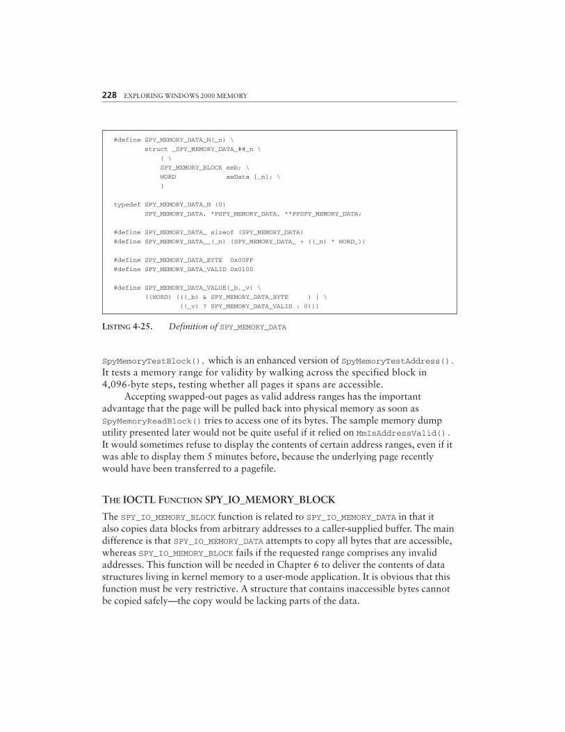
228 EXPLORING WINDOWS 2000 MEMORY
#define SPY_MEMORY_DATA_N(_n) \
struct _SPY_MEMORY_DATA_##_n \
{ \
SPY_MEMORY_BLOCK smb; \
WORD awData [_n]; \
}
typedef SPY_MEMORY_DATA_N (0)
SPY_MEMORY_DATA, *PSPY_MEMORY_DATA, **PPSPY_MEMORY_DATA;
#define SPY_MEMORY_DATA_ sizeof (SPY_MEMORY_DATA)
#define SPY_MEMORY_DATA__(_n) (SPY_MEMORY_DATA_ + ((_n) * WORD_))
#define SPY_MEMORY_DATA_BYTE 0x00FF
#define SPY_MEMORY_DATA_VALID 0x0100
#define SPY_MEMORY_DATA_VALUE(_b,_v) \
((WORD) (((_b) & SPY_MEMORY_DATA_BYTE ) | \
((_v) ? SPY_MEMORY_DATA_VALID : 0)))
LISTING 4-25. Definition of SPY_MEMORY_DATA
SpyMemoryTestBlock(), which is an enhanced version of SpyMemoryTestAddress().It tests a memory range for validity by walking across the specified block in4,096-byte steps, testing whether all pages it spans are accessible.
Accepting swapped-out pages as valid address ranges has the importantadvantage that the page will be pulled back into physical memory as soon asSpyMemoryReadBlock() tries to access one of its bytes. The sample memory dumputility presented later would not be quite useful if it relied on MmIsAddressValid().It would sometimes refuse to display the contents of certain address ranges, even if itwas able to display them 5 minutes before, because the underlying page recentlywould have been transferred to a pagefile.
THE IOCTL FUNCTION SPY_IO_MEMORY_BLOCK
The SPY_IO_MEMORY_BLOCK function is related to SPY_IO_MEMORY_DATA in that italso copies data blocks from arbitrary addresses to a caller-supplied buffer. The maindifference is that SPY_IO_MEMORY_DATA attempts to copy all bytes that are accessible,whereas SPY_IO_MEMORY_BLOCK fails if the requested range comprises any invalidaddresses. This function will be needed in Chapter 6 to deliver the contents of datastructures living in kernel memory to a user-mode application. It is obvious that thisfunction must be very restrictive. A structure that contains inaccessible bytes cannotbe copied safely—the copy would be lacking parts of the data.
A SAMPLE MEMORY SPY DEVICE 229
Like SPY_IO_MEMORY_DATA, the SPY_IO_MEMORY_BLOCK function expects inputin the form of a SPY_MEMORY_BLOCK structure that specifies the base address and sizeof the memory range to be copied. The returned copy is a faithful 1:1 reproduction ofthe original data. The output buffer must be large enough to hold the entire copy.Otherwise, an error is reported, and no data is sent back.
THE IOCTL FUNCTION SPY_IO_HANDLE_INFO
Like the SPY_IO_PHYSICAL function introduced above, this function allows a user-modeapplication to call kernel-mode API functions that are otherwise unreachable. A kernel-mode driver can always get a pointer to an object represented by a handle by simply call-ing the ntoskrnl.exe function ObReferenceObjectByHandle(). There is no equivalentfunction in the Win32 API. However, the application can instruct the spy device toexecute the function call on its behalf and to return the object pointer afterward. List-ing 4-26 shows the SpyOutputHandleInfo() function called by the SpyDispatcher()after obtaining the input handle via SpyInputHandle(), defined in Listing 4-10.
The SPY_HANDLE_INFO structure at the beginning of Listing 4-26 receives thepointer to the body of the object associated with the handle and the handle attrib-utes, both returned by ObReferenceObjectByHandle(). It is important to callObDereferenceObject() if ObReferenceObjectByHandle() reports success to resetthe object’s pointer reference count to its previous value. Failing to do so constitutesan “object reference leak.”
typedef struct _SPY_HANDLE_INFO
{
PVOID pObjectBody;
DWORD dHandleAttributes;
}
SPY_HANDLE_INFO, *PSPY_HANDLE_INFO, **PPSPY_HANDLE_INFO;
#define SPY_HANDLE_INFO_ sizeof (SPY_HANDLE_INFO)
// -----------------------------------------------------------------
NTSTATUS SpyOutputHandleInfo (HANDLE hObject,
PVOID pOutput,
DWORD dOutput,
PDWORD pdInfo)
{
SPY_HANDLE_INFO shi;
OBJECT_HANDLE_INFORMATION ohi;
NTSTATUS ns = STATUS_INVALID_PARAMETER;
(continued)
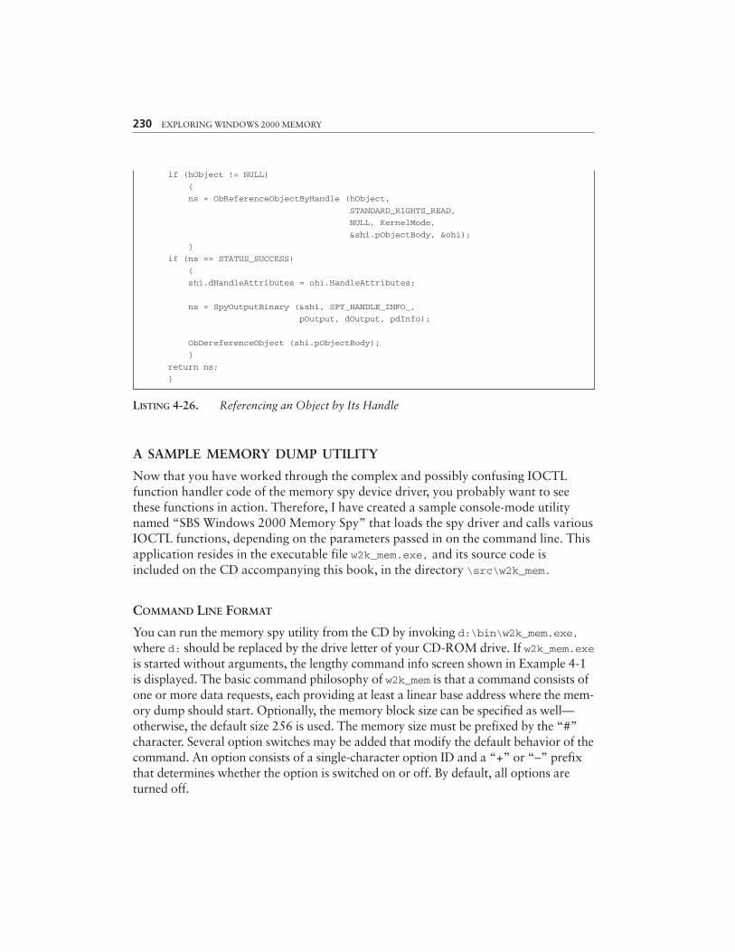
230 EXPLORING WINDOWS 2000 MEMORY
if (hObject != NULL)
{
ns = ObReferenceObjectByHandle (hObject,
STANDARD_RIGHTS_READ,
NULL, KernelMode,
&shi.pObjectBody, &ohi);
}
if (ns == STATUS_SUCCESS)
{
shi.dHandleAttributes = ohi.HandleAttributes;
ns = SpyOutputBinary (&shi, SPY_HANDLE_INFO_,
pOutput, dOutput, pdInfo);
ObDereferenceObject (shi.pObjectBody);
}
return ns;
}
LISTING 4-26. Referencing an Object by Its Handle
A SAMPLE MEMORY DUMP UTILITY
Now that you have worked through the complex and possibly confusing IOCTLfunction handler code of the memory spy device driver, you probably want to seethese functions in action. Therefore, I have created a sample console-mode utilitynamed “SBS Windows 2000 Memory Spy” that loads the spy driver and calls variousIOCTL functions, depending on the parameters passed in on the command line. Thisapplication resides in the executable file w2k_mem.exe, and its source code isincluded on the CD accompanying this book, in the directory \src\w2k_mem.
COMMAND LINE FORMAT
You can run the memory spy utility from the CD by invoking d:\bin\w2k_mem.exe,where d: should be replaced by the drive letter of your CD-ROM drive. If w2k_mem.exeis started without arguments, the lengthy command info screen shown in Example 4-1is displayed. The basic command philosophy of w2k_mem is that a command consists ofone or more data requests, each providing at least a linear base address where the mem-ory dump should start. Optionally, the memory block size can be specified as well—otherwise, the default size 256 is used. The memory size must be prefixed by the “#”character. Several option switches may be added that modify the default behavior of thecommand. An option consists of a single-character option ID and a “+” or “–” prefixthat determines whether the option is switched on or off. By default, all options areturned off.
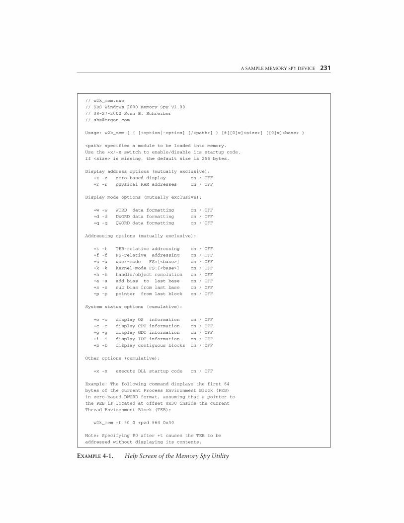
A SAMPLE MEMORY SPY DEVICE 231
// w2k_mem.exe
// SBS Windows 2000 Memory Spy V1.00
// 08-27-2000 Sven B. Schreiber
Usage: w2k_mem { { [+option|-option] [/<path>] } [#[[0]x]<size>] [[0]x]<base> }
<path> specifies a module to be loaded into memory.
Use the +x/-x switch to enable/disable its startup code.
If <size> is missing, the default size is 256 bytes.
Display address options (mutually exclusive):
+z -z zero-based display on / OFF
+r -r physical RAM addresses on / OFF
Display mode options (mutually exclusive):
+w -w WORD data formatting on / OFF
+d -d DWORD data formatting on / OFF
+q -q QWORD data formatting on / OFF
Addressing options (mutually exclusive):
+t -t TEB-relative addressing on / OFF
+f -f FS-relative addressing on / OFF
+u -u user-mode FS:[<base>] on / OFF
+k -k kernel-mode FS:[<base>] on / OFF
+h -h handle/object resolution on / OFF
+a -a add bias to last base on / OFF
+s -s sub bias from last base on / OFF
+p -p pointer from last block on / OFF
System status options (cumulative):
+o -o display OS information on / OFF
+c -c display CPU information on / OFF
+g -g display GDT information on / OFF
+i -i display IDT information on / OFF
+b -b display contiguous blocks on / OFF
Other options (cumulative):
+x -x execute DLL startup code on / OFF
Example: The following command displays the first 64
bytes of the current Process Environment Block (PEB)
in zero-based DWORD format, assuming that a pointer to
the PEB is located at offset 0x30 inside the current
Thread Environment Block (TEB):
w2k_mem +t #0 0 +pzd #64 0x30
Note: Specifying #0 after +t causes the TEB to be
addressed without displaying its contents.
EXAMPLE 4-1. Help Screen of the Memory Spy Utility
A data request is executed for each command line token that cannot be identi-fied as an option, a data block size specification, a path, or any other commandmodifier. Each plain number on the command line is assumed to specify a linearaddress and triggers a hex dump, starting at this address. Numbers are interpretedas decimal by default or hexadecimal if prefixed by “0x” or simply “x.”
Complex command line option models like the one employed byw2k_mem.exe are much easier to grasp if some simple examples are provided.Here is a short compilation:
• w2k_mem 0x80400000 displays the first 256 bytes of memory at linearaddress 0x80400000, yielding something that should look similar toExample 4-2. By the way, this is the DOS header of the ntoskrnl.exemodule (note the “MZ” ID at the beginning).
• w2k_mem #0x40 0x80400000 displays the same data block, but stops after64 bytes, as demanded by the block size specification #0x40.
• w2k_mem +d #0x40 0x80400000 is another variant, this time packing thebytes into 32-bit DWORD chunks because of the +d option. This optionremains in effect until reset by —d or overridden by a competingoption such as +w or +q.
• w2k_mem +wz #0x40 0x10000 +d —z 0x20000 contains two datarequests. First, the linear address range 0x10000 to 0x1003F is shown in16-bit WORD format, followed by the range 0x20000 to 0x2003F in DWORDformat (Example 4-3). The first request also includes the +z switch,which forces the numbers in the “Address” column to start at zero. Inthe second request, the zero-based display mode is turned off by addinga –z switch.
• w2k_mem +rd #4096 0xC0300000 displays the system’s page-directory ataddress 0xC0300000 in DWORD format. The +r option enables the display ofphysical RAM addresses in the “Address” column instead of linear ones.
By now, you should have a basic understanding of how the command lineformat works. In the following subsections, some of the more exotic options andfeatures are discussed in more detail. Most of them alter the interpretation of theaddress parameter they precede. In default mode, the specified address is a linearbase address where the memory dump starts. The options +t, +f, +u, +k, +h,+a, +s, and +p change this default interpretation in various ways.
232 EXPLORING WINDOWS 2000 MEMORY
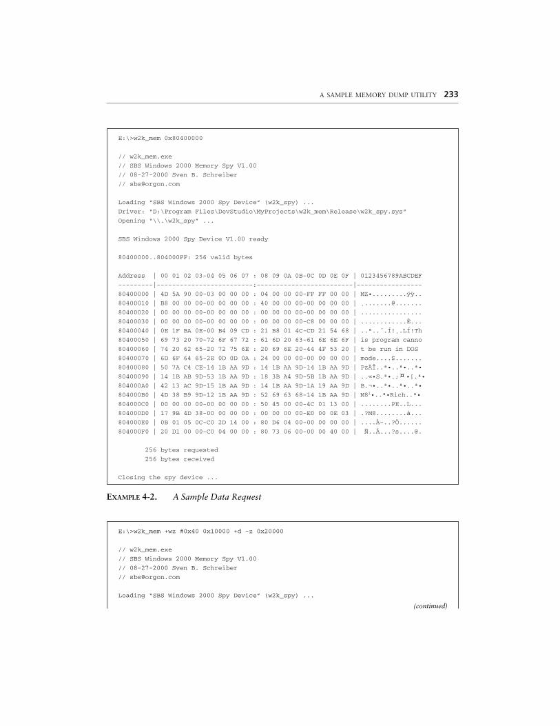
A SAMPLE MEMORY DUMP UTILITY 233
E:\>w2k_mem 0x80400000
// w2k_mem.exe
// SBS Windows 2000 Memory Spy V1.00
// 08-27-2000 Sven B. Schreiber
Loading “SBS Windows 2000 Spy Device” (w2k_spy) ...
Driver: “D:\Program Files\DevStudio\MyProjects\w2k_mem\Release\w2k_spy.sys”
Opening “\\.\w2k_spy” ...
SBS Windows 2000 Spy Device V1.00 ready
80400000..804000FF: 256 valid bytes
Address | 00 01 02 03-04 05 06 07 : 08 09 0A 0B-0C 0D 0E 0F | 0123456789ABCDEF
---------|-------------------------:-------------------------|-----------------
80400000 | 4D 5A 90 00-03 00 00 00 : 04 00 00 00-FF FF 00 00 | MZ•.........ÿÿ..
80400010 | B8 00 00 00-00 00 00 00 : 40 00 00 00-00 00 00 00 | ¸.......@.......
80400020 | 00 00 00 00-00 00 00 00 : 00 00 00 00-00 00 00 00 | ................
80400030 | 00 00 00 00-00 00 00 00 : 00 00 00 00-C8 00 00 00 | ............È...
80400040 | 0E 1F BA 0E-00 B4 09 CD : 21 B8 01 4C-CD 21 54 68 | ..º..´.Í!¸.LÍ!Th
80400050 | 69 73 20 70-72 6F 67 72 : 61 6D 20 63-61 6E 6E 6F | is program canno
80400060 | 74 20 62 65-20 72 75 6E : 20 69 6E 20-44 4F 53 20 | t be run in DOS
80400070 | 6D 6F 64 65-2E 0D 0D 0A : 24 00 00 00-00 00 00 00 | mode....$.......
80400080 | 50 7A C4 CE-14 1B AA 9D : 14 1B AA 9D-14 1B AA 9D | PzÄÎ..ª•..ª•..ª•
80400090 | 14 1B AB 9D-53 1B AA 9D : 18 3B A4 9D-5B 1B AA 9D | ..«•S.ª•.; •[.ª•
804000A0 | 42 13 AC 9D-15 1B AA 9D : 14 1B AA 9D-1A 19 AA 9D | B.¬•..ª•..ª•..ª•
804000B0 | 4D 38 B9 9D-12 1B AA 9D : 52 69 63 68-14 1B AA 9D | M81•..ª•Rich..ª•
804000C0 | 00 00 00 00-00 00 00 00 : 50 45 00 00-4C 01 13 00 | ........PE..L...
804000D0 | 17 9B 4D 38-00 00 00 00 : 00 00 00 00-E0 00 0E 03 | .?M8........à...
804000E0 | 0B 01 05 0C-C0 2D 14 00 : 80 D6 04 00-00 00 00 00 | ....À-..?Ö......
804000F0 | 20 D1 00 00-C0 04 00 00 : 80 73 06 00-00 00 40 00 | Ñ..À...?s....@.
256 bytes requested
256 bytes received
Closing the spy device ...
¤
EXAMPLE 4-2. A Sample Data Request
E:\>w2k_mem +wz #0x40 0x10000 +d -z 0x20000
// w2k_mem.exe
// SBS Windows 2000 Memory Spy V1.00
// 08-27-2000 Sven B. Schreiber
Loading “SBS Windows 2000 Spy Device” (w2k_spy) ...
(continued)
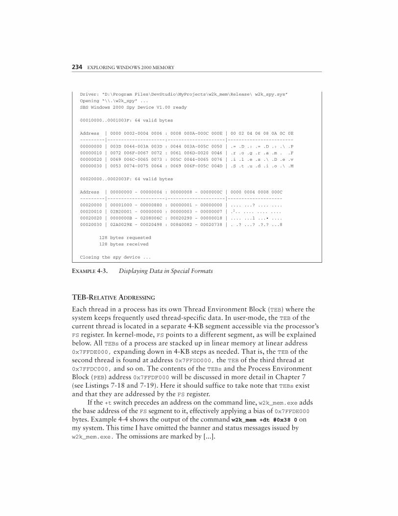
EXAMPLE 4-3. Displaying Data in Special Formats
TEB-RELATIVE ADDRESSING
Each thread in a process has its own Thread Environment Block (TEB) where thesystem keeps frequently used thread-specific data. In user-mode, the TEB of thecurrent thread is located in a separate 4-KB segment accessible via the processor’sFS register. In kernel-mode, FS points to a different segment, as will be explainedbelow. All TEBs of a process are stacked up in linear memory at linear address0x7FFDE000, expanding down in 4-KB steps as needed. That is, the TEB of thesecond thread is found at address 0x7FFDD000, the TEB of the third thread at0x7FFDC000, and so on. The contents of the TEBs and the Process EnvironmentBlock (PEB) address 0x7FFDF000 will be discussed in more detail in Chapter 7(see Listings 7-18 and 7-19). Here it should suffice to take note that TEBs existand that they are addressed by the FS register.
If the +t switch precedes an address on the command line, w2k_mem.exe addsthe base address of the FS segment to it, effectively applying a bias of 0x7FFDE000bytes. Example 4-4 shows the output of the command w2k_mem +dt #0x38 0 onmy system. This time I have omitted the banner and status messages issued byw2k_mem.exe. The omissions are marked by [...].
234 EXPLORING WINDOWS 2000 MEMORY
Driver: “D:\Program Files\DevStudio\MyProjects\w2k_mem\Release\ w2k_spy.sys”
Opening “\\.\w2k_spy” ...
SBS Windows 2000 Spy Device V1.00 ready
00010000..0001003F: 64 valid bytes
Address | 0000 0002-0004 0006 : 0008 000A-000C 000E | 00 02 04 06 08 0A 0C 0E
---------|---------------------:---------------------|------------------------
00000000 | 003D 0044-003A 003D : 0044 003A-005C 0050 | .= .D .: .= .D .: .\ .P
00000010 | 0072 006F-0067 0072 : 0061 006D-0020 0046 | .r .o .g .r .a .m . .F
00000020 | 0069 006C-0065 0073 : 005C 0044-0065 0076 | .i .l .e .s .\ .D .e .v
00000030 | 0053 0074-0075 0064 : 0069 006F-005C 004D | .S .t .u .d .i .o .\ .M
00020000..0002003F: 64 valid bytes
Address | 00000000 - 00000004 : 00000008 - 0000000C | 0000 0004 0008 000C
---------|---------------------:---------------------|--------------------
00020000 | 00001000 - 00000880 : 00000001 - 00000000 | .... ...? .... ....
00020010 | 02B20001 - 00000000 : 00000003 - 00000007 | .2.. .... .... ....
00020020 | 0000000B - 0208006C : 00020290 - 00000018 | .... ...l ...• ....
00020030 | 02A0029E - 00020498 : 00840082 - 00020738 | . .? ...? .?.? ...8
128 bytes requested
128 bytes received
Closing the spy device ...

A SAMPLE MEMORY DUMP UTILITY 235
E:\>w2k_mem +dt #0x38 0
[...]
7FFDE000..7FFDE037: 56 valid bytes
Address | 00000000 - 00000004 : 00000008 - 0000000C | 0000 0004 0008 000C
---------|---------------------:---------------------|--------------------
7FFDE000 | 0012FA58 - 00130000 : 0012E000 - 00000000 | ..úX .... ..à. ....
7FFDE010 | 00001E00 - 00000000 : 7FFDE000 - 00000000 | .... .... .yà. ....
7FFDE020 | 000002C0 - 000002C8 : 00000000 - 00000000 | ...À ...È .... ....
7FFDE030 | 7FFDF000 - 00000000 : - | .yô. ....
[...]
EXAMPLE 4-4. Displaying the first Thread Environment Block (TEB)
FS-RELATIVE ADDRESSING
I have already mentioned that the FS refers to different segments in user- and kernel-mode. Whereas the +t switch selects the user-mode FS address as the reference point, the+f switch uses the FS base address that is in effect in kernel-mode. Of course, a Win32application has no way to get at this value, so once again the spy device is required.w2k_mem.exe calls the IOCTL function SPY_IO_CPU_INFO, introduced in the previoussection, to read CPU status information that includes the kernel-mode values of all seg-ment registers. From there, everything goes on just the same as with the +t switch.
The kernel-mode FS points to another thread-specific structure frequentlyaccessed by the Windows 2000 kernel, named the Kernel’s Processor Control Region(KPCR). This structure has already been mentioned in the course of the discussion of theIOCTL function SPY_IO_OS_INFO and will be revisited in Chapter 7 (see Listing 7-16).Again, suffice it to note for now that this structure exists at linear address 0xFFDFF000,and that the +f switch gives easy access to it. In Example 4-5, I have issued the com-mand w2k_mem +df #0x54 0 to demonstrate that the +f switch in fact applies a biasof 0xFFDFF000 bytes to the specified memory address.
E:\>w2k_mem +df #0x54 0
[...]
FFDFF000..FFDFF053: 84 valid bytes
Address | 00000000 - 00000004 : 00000008 - 0000000C | 0000 0004 0008 000C
---------|---------------------:---------------------|--------------------
FFDFF000 | BECD9CF0 - BECD9DF0 : BECD6000 - 00000000 | 3/4Í?Ô 3/4Í•Õ 3/4Í`. ....
FFDFF010 | 00000000 - 00000000 : 7FFDE000 - FFDFF000 | .... .... .yà. ÿßÕ.
FFDFF020 | FFDFF120 - 00000000 : 00000000 - 00000000 | ÿßñ .... .... ....
FFDFF030 | FFFF20C0 - 00000000 : 80036400 - 80036000 | ÿÿ À .... ?.d. ?.`.
FFDFF040 | 80244000 - 00010001 : 00000001 - 000000C9 | ?$@. .... .... ...ÉFFDFF050 | 00000000 - : - | ....
[...]
EXAMPLE 4-5. Displaying the Kernel’s Processor Control Region (KPCR)
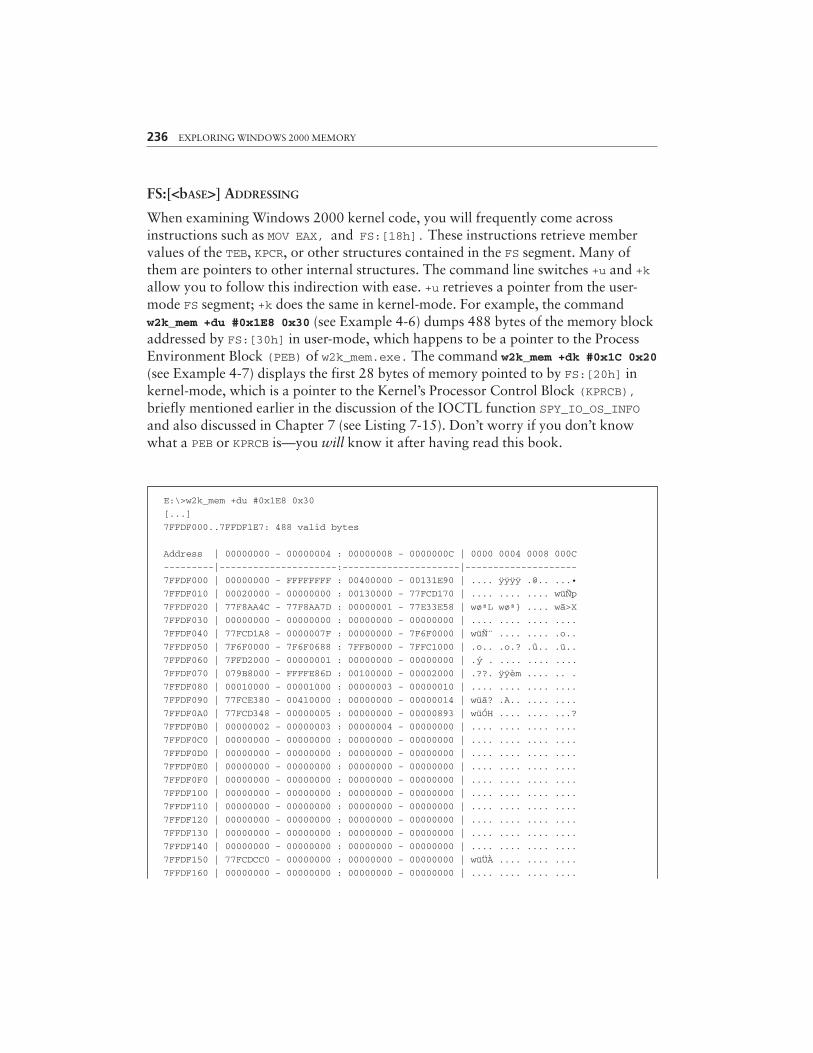
236 EXPLORING WINDOWS 2000 MEMORY
FS:[<bASE>] ADDRESSING
When examining Windows 2000 kernel code, you will frequently come acrossinstructions such as MOV EAX, and FS:[18h]. These instructions retrieve membervalues of the TEB, KPCR, or other structures contained in the FS segment. Many ofthem are pointers to other internal structures. The command line switches +u and +kallow you to follow this indirection with ease. +u retrieves a pointer from the user-mode FS segment; +k does the same in kernel-mode. For example, the commandw2k_mem +du #0x1E8 0x30 (see Example 4-6) dumps 488 bytes of the memory blockaddressed by FS:[30h] in user-mode, which happens to be a pointer to the ProcessEnvironment Block (PEB) of w2k_mem.exe. The command w2k_mem +dk #0x1C 0x20(see Example 4-7) displays the first 28 bytes of memory pointed to by FS:[20h] inkernel-mode, which is a pointer to the Kernel’s Processor Control Block (KPRCB),briefly mentioned earlier in the discussion of the IOCTL function SPY_IO_OS_INFOand also discussed in Chapter 7 (see Listing 7-15). Don’t worry if you don’t knowwhat a PEB or KPRCB is—you will know it after having read this book.
E:\>w2k_mem +du #0x1E8 0x30
[...]
7FFDF000..7FFDF1E7: 488 valid bytes
Address | 00000000 - 00000004 : 00000008 - 0000000C | 0000 0004 0008 000C
---------|---------------------:---------------------|--------------------
7FFDF000 | 00000000 - FFFFFFFF : 00400000 - 00131E90 | .... ÿÿÿÿ .@.. ...•
7FFDF010 | 00020000 - 00000000 : 00130000 - 77FCD170 | .... .... .... wüÑp
7FFDF020 | 77F8AA4C - 77F8AA7D : 00000001 - 77E33E58 | wøªL wøª} .... wã>X
7FFDF030 | 00000000 - 00000000 : 00000000 - 00000000 | .... .... .... ....
7FFDF040 | 77FCD1A8 - 0000007F : 00000000 - 7F6F0000 | wüѨ .... .... .o..
7FFDF050 | 7F6F0000 - 7F6F0688 : 7FFB0000 - 7FFC1000 | .o.. .o.? .û.. .ü..
7FFDF060 | 7FFD2000 - 00000001 : 00000000 - 00000000 | .y . .... .... ....
7FFDF070 | 079B8000 - FFFFE86D : 00100000 - 00002000 | .??. ÿÿèm .... .. .
7FFDF080 | 00010000 - 00001000 : 00000003 - 00000010 | .... .... .... ....
7FFDF090 | 77FCE380 - 00410000 : 00000000 - 00000014 | wüã? .A.. .... ....
7FFDF0A0 | 77FCD348 - 00000005 : 00000000 - 00000893 | wüÓH .... .... ...?
7FFDF0B0 | 00000002 - 00000003 : 00000004 - 00000000 | .... .... .... ....
7FFDF0C0 | 00000000 - 00000000 : 00000000 - 00000000 | .... .... .... ....
7FFDF0D0 | 00000000 - 00000000 : 00000000 - 00000000 | .... .... .... ....
7FFDF0E0 | 00000000 - 00000000 : 00000000 - 00000000 | .... .... .... ....
7FFDF0F0 | 00000000 - 00000000 : 00000000 - 00000000 | .... .... .... ....
7FFDF100 | 00000000 - 00000000 : 00000000 - 00000000 | .... .... .... ....
7FFDF110 | 00000000 - 00000000 : 00000000 - 00000000 | .... .... .... ....
7FFDF120 | 00000000 - 00000000 : 00000000 - 00000000 | .... .... .... ....
7FFDF130 | 00000000 - 00000000 : 00000000 - 00000000 | .... .... .... ....
7FFDF140 | 00000000 - 00000000 : 00000000 - 00000000 | .... .... .... ....
7FFDF150 | 77FCDCC0 - 00000000 : 00000000 - 00000000 | wüÜÀ .... .... ....
7FFDF160 | 00000000 - 00000000 : 00000000 - 00000000 | .... .... .... ....
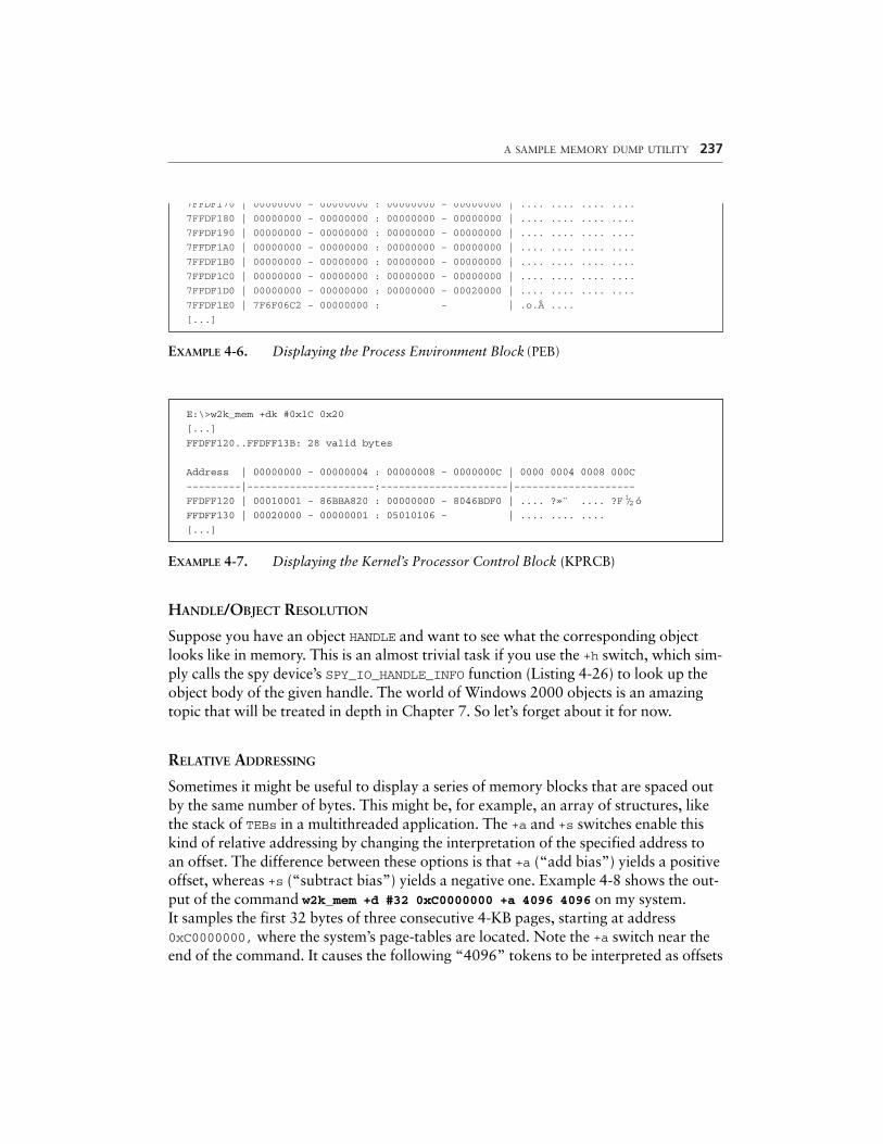
A SAMPLE MEMORY DUMP UTILITY 237
7FFDF170 | 00000000 - 00000000 : 00000000 - 00000000 | .... .... .... ....
7FFDF180 | 00000000 - 00000000 : 00000000 - 00000000 | .... .... .... ....
7FFDF190 | 00000000 - 00000000 : 00000000 - 00000000 | .... .... .... ....
7FFDF1A0 | 00000000 - 00000000 : 00000000 - 00000000 | .... .... .... ....
7FFDF1B0 | 00000000 - 00000000 : 00000000 - 00000000 | .... .... .... ....
7FFDF1C0 | 00000000 - 00000000 : 00000000 - 00000000 | .... .... .... ....
7FFDF1D0 | 00000000 - 00000000 : 00000000 - 00020000 | .... .... .... ....
7FFDF1E0 | 7F6F06C2 - 00000000 : - | .o. ....
[...]
EXAMPLE 4-6. Displaying the Process Environment Block (PEB)
E:\>w2k_mem +dk #0x1C 0x20
[...]
FFDFF120..FFDFF13B: 28 valid bytes
Address | 00000000 - 00000004 : 00000008 - 0000000C | 0000 0004 0008 000C
---------|---------------------:---------------------|--------------------
FFDFF120 | 00010001 - 86BBA820 : 00000000 - 8046BDF0 | .... ?»¨ .... ?F 1/2ó
FFDFF130 | 00020000 - 00000001 : 05010106 - | .... .... ....
[...]
EXAMPLE 4-7. Displaying the Kernel’s Processor Control Block (KPRCB)
HANDLE/OBJECT RESOLUTION
Suppose you have an object HANDLE and want to see what the corresponding objectlooks like in memory. This is an almost trivial task if you use the +h switch, which sim-ply calls the spy device’s SPY_IO_HANDLE_INFO function (Listing 4-26) to look up theobject body of the given handle. The world of Windows 2000 objects is an amazingtopic that will be treated in depth in Chapter 7. So let’s forget about it for now.
RELATIVE ADDRESSING
Sometimes it might be useful to display a series of memory blocks that are spaced outby the same number of bytes. This might be, for example, an array of structures, likethe stack of TEBs in a multithreaded application. The +a and +s switches enable thiskind of relative addressing by changing the interpretation of the specified address toan offset. The difference between these options is that +a (“add bias”) yields a positiveoffset, whereas +s (“subtract bias”) yields a negative one. Example 4-8 shows the out-put of the command w2k_mem +d #32 0xC0000000 +a 4096 4096 on my system.It samples the first 32 bytes of three consecutive 4-KB pages, starting at address0xC0000000, where the system’s page-tables are located. Note the +a switch near theend of the command. It causes the following “4096” tokens to be interpreted as offsets
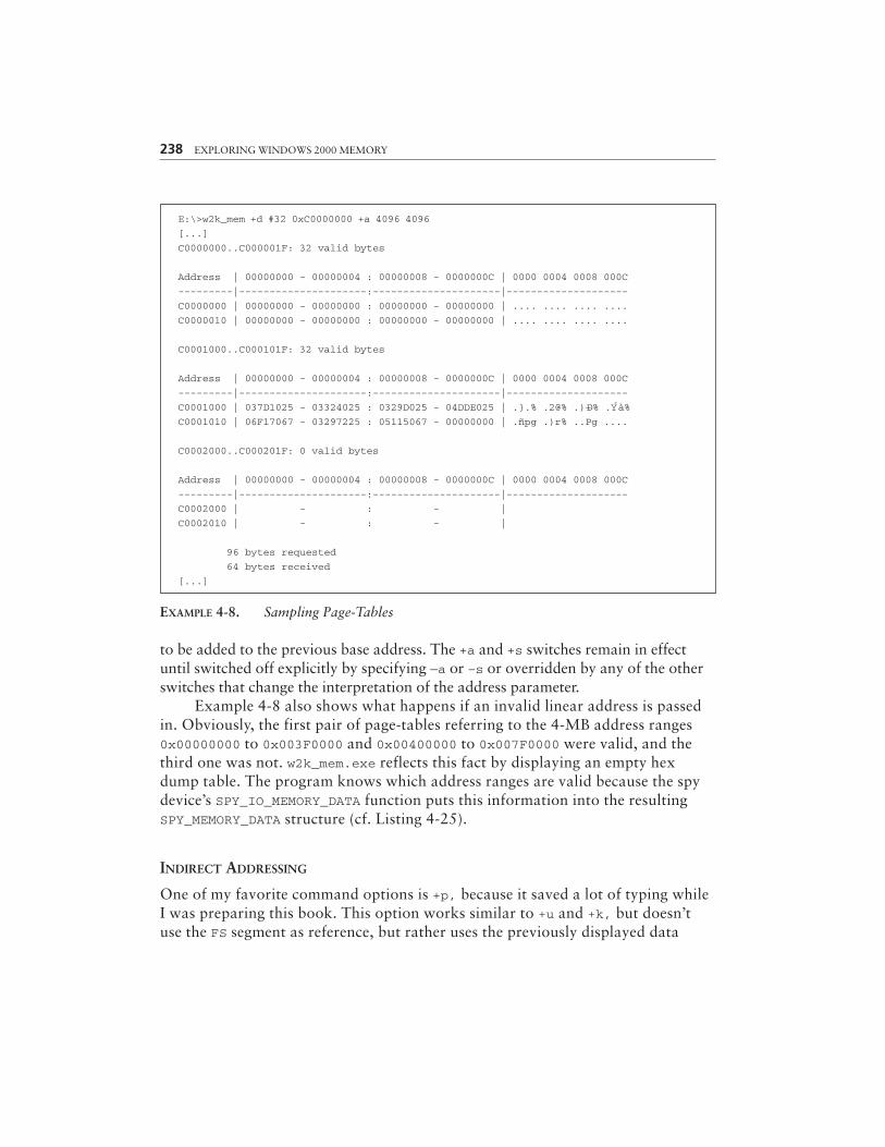
238 EXPLORING WINDOWS 2000 MEMORY
E:\>w2k_mem +d #32 0xC0000000 +a 4096 4096
[...]
C0000000..C000001F: 32 valid bytes
Address | 00000000 - 00000004 : 00000008 - 0000000C | 0000 0004 0008 000C
---------|---------------------:---------------------|--------------------
C0000000 | 00000000 - 00000000 : 00000000 - 00000000 | .... .... .... ....
C0000010 | 00000000 - 00000000 : 00000000 - 00000000 | .... .... .... ....
C0001000..C000101F: 32 valid bytes
Address | 00000000 - 00000004 : 00000008 - 0000000C | 0000 0004 0008 000C
---------|---------------------:---------------------|--------------------
C0001000 | 037D1025 - 03324025 : 0329D025 - 04DDE025 | .}.% .2@% .)–D% .Yà%
C0001010 | 06F17067 - 03297225 : 05115067 - 00000000 | .ñpg .)r% ..Pg ....
C0002000..C000201F: 0 valid bytes
Address | 00000000 - 00000004 : 00000008 - 0000000C | 0000 0004 0008 000C
---------|---------------------:---------------------|--------------------
C0002000 | - : - |
C0002010 | - : - |
96 bytes requested
64 bytes received
[...]
EXAMPLE 4-8. Sampling Page-Tables
to be added to the previous base address. The +a and +s switches remain in effectuntil switched off explicitly by specifying —a or –s or overridden by any of the otherswitches that change the interpretation of the address parameter.
Example 4-8 also shows what happens if an invalid linear address is passedin. Obviously, the first pair of page-tables referring to the 4-MB address ranges0x00000000 to 0x003F0000 and 0x00400000 to 0x007F0000 were valid, and thethird one was not. w2k_mem.exe reflects this fact by displaying an empty hexdump table. The program knows which address ranges are valid because the spydevice’s SPY_IO_MEMORY_DATA function puts this information into the resultingSPY_MEMORY_DATA structure (cf. Listing 4-25).
INDIRECT ADDRESSING
One of my favorite command options is +p, because it saved a lot of typing whileI was preparing this book. This option works similar to +u and +k, but doesn’tuse the FS segment as reference, but rather uses the previously displayed data

block. This is a great feature if you want to chase down a linked list of objects, forexample. Instead of displaying the first list member, reading out the address of thenext member, typing a new command with this address, and so on, simply append+p to the command and a series of offsets that specify where the link to the nextobject is located in the previous hex dump panel.
In Example 4-9, I have used this option to walk down the list of activeprocesses. First, I have asked the Kernel Debugger to give me the address of theinternal variable PsActiveProcessHead, which is a LIST_ENTRY structure mark-ing the beginning of the process list. A LIST_ENTRY consists of a Flink (forwardlink) member at offset 0 and a Blink (backward link) member at offset 4 (cf.Listing 2-7). The command w2k_mem #8 +d 0x8046a180 +p 0 0 0 0 first dumpsthe LIST_ENTRY of PsActiveProcessHead, and then it switches to indirectaddressing on behalf of the +p switch. The four zeros tell w2k_mem.exe to extractthe value at offset zero of the previous data block, which is, of course, the Flinkmember of each LIST_ENTRY. Note that the Blink members in Example 4-9,located at offset 4, do in fact point back to the previous LIST_ENTRY, as expected.
If enough zero-valued parameters would be appended to the command, the hexdump would eventually return to PsActiveProcessHead, which marks the beginningand the end of the process list. As explained in Chapter 2, the doubly-linked lists main-tained by Windows 2000 are usually circular; that is, the Flink of the last list memberpoints to the first one, and the Blink of the first list member points to the last one.
A SAMPLE MEMORY DUMP UTILITY 239
E:\>w2k_mem #8 +d 0x8046a180 +p 0 0 0 0
[...]
8046A180..8046A187: 8 valid bytes
Address | 00000000 - 00000004 : 00000008 - 0000000C | 0000 0004 0008 000C
---------|---------------------:---------------------|--------------------
8046A180 | 8149D900 - 840D2BE0 : - | •IÙ. ?.+à
8149D900..8149D907: 8 valid bytes
Address | 00000000 - 00000004 : 00000008 - 0000000C | 0000 0004 0008 000C
---------|---------------------:---------------------|--------------------
8149D900 | 8131A4A0 - 8046A180 : - | •1 ?F¡?
8131A4A0..8131A4A7: 8 valid bytes
Address | 00000000 - 00000004 : 00000008 - 0000000C | 0000 0004 0008 000C---------|---------------------:---------------------|--------------------
8131A4A0 | 812FFDE0 - 8149D900 : - | •/yà •IÙ.
812FFDE0..812FFDE7: 8 valid bytes
¤
(continued)
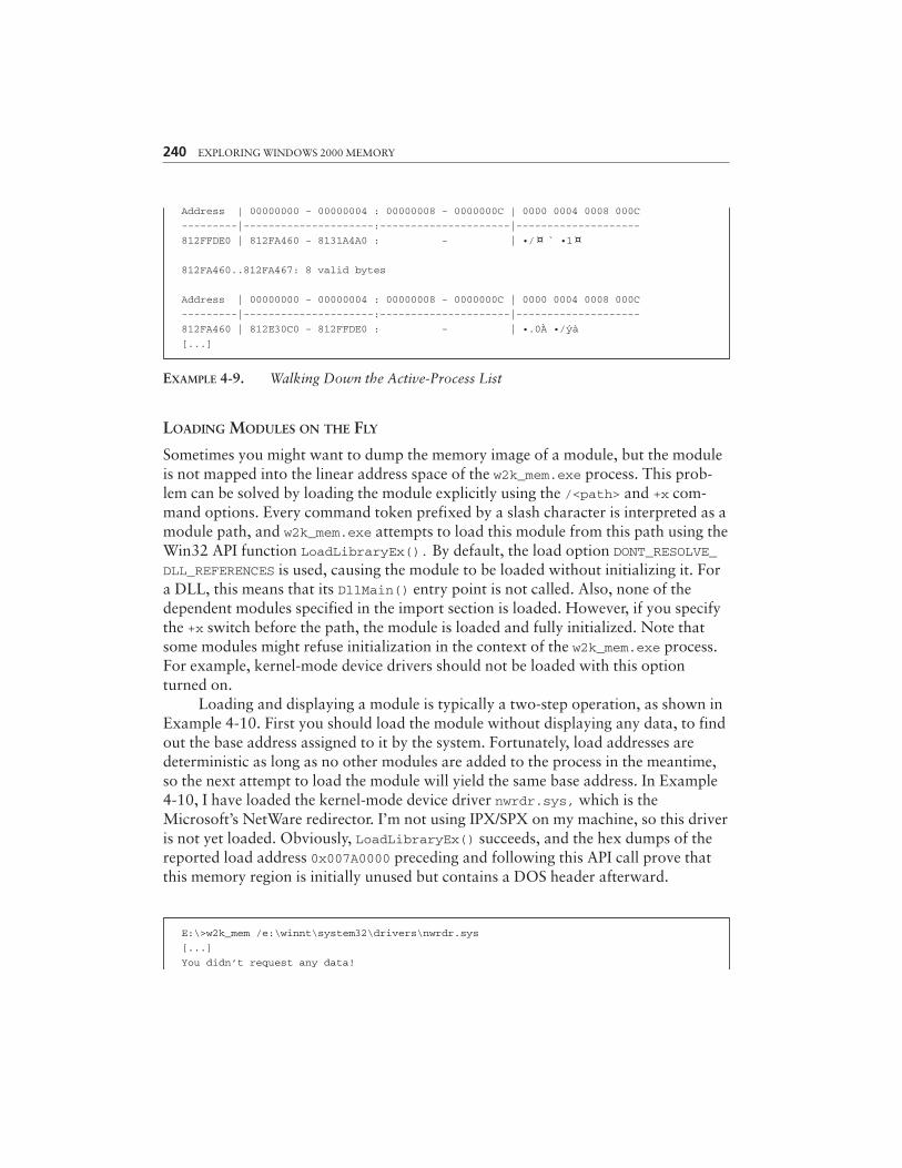
EXAMPLE 4-9. Walking Down the Active-Process List
LOADING MODULES ON THE FLY
Sometimes you might want to dump the memory image of a module, but the moduleis not mapped into the linear address space of the w2k_mem.exe process. This prob-lem can be solved by loading the module explicitly using the /<path> and +x com-mand options. Every command token prefixed by a slash character is interpreted as amodule path, and w2k_mem.exe attempts to load this module from this path using theWin32 API function LoadLibraryEx(). By default, the load option DONT_RESOLVE_DLL_REFERENCES is used, causing the module to be loaded without initializing it. Fora DLL, this means that its DllMain() entry point is not called. Also, none of thedependent modules specified in the import section is loaded. However, if you specifythe +x switch before the path, the module is loaded and fully initialized. Note thatsome modules might refuse initialization in the context of the w2k_mem.exe process.For example, kernel-mode device drivers should not be loaded with this optionturned on.
Loading and displaying a module is typically a two-step operation, as shown inExample 4-10. First you should load the module without displaying any data, to findout the base address assigned to it by the system. Fortunately, load addresses aredeterministic as long as no other modules are added to the process in the meantime,so the next attempt to load the module will yield the same base address. In Example4-10, I have loaded the kernel-mode device driver nwrdr.sys, which is theMicrosoft’s NetWare redirector. I’m not using IPX/SPX on my machine, so this driveris not yet loaded. Obviously, LoadLibraryEx() succeeds, and the hex dumps of thereported load address 0x007A0000 preceding and following this API call prove thatthis memory region is initially unused but contains a DOS header afterward.
240 EXPLORING WINDOWS 2000 MEMORY
Address | 00000000 - 00000004 : 00000008 - 0000000C | 0000 0004 0008 000C
---------|---------------------:---------------------|--------------------
812FFDE0 | 812FA460 - 8131A4A0 : - | •/ ` •1
812FA460..812FA467: 8 valid bytes
Address | 00000000 - 00000004 : 00000008 - 0000000C | 0000 0004 0008 000C
---------|---------------------:---------------------|--------------------
812FA460 | 812E30C0 - 812FFDE0 : - | •.0À •/yà
[...]
¤¤
E:\>w2k_mem /e:\winnt\system32\drivers\nwrdr.sys
[...]
You didn’t request any data!
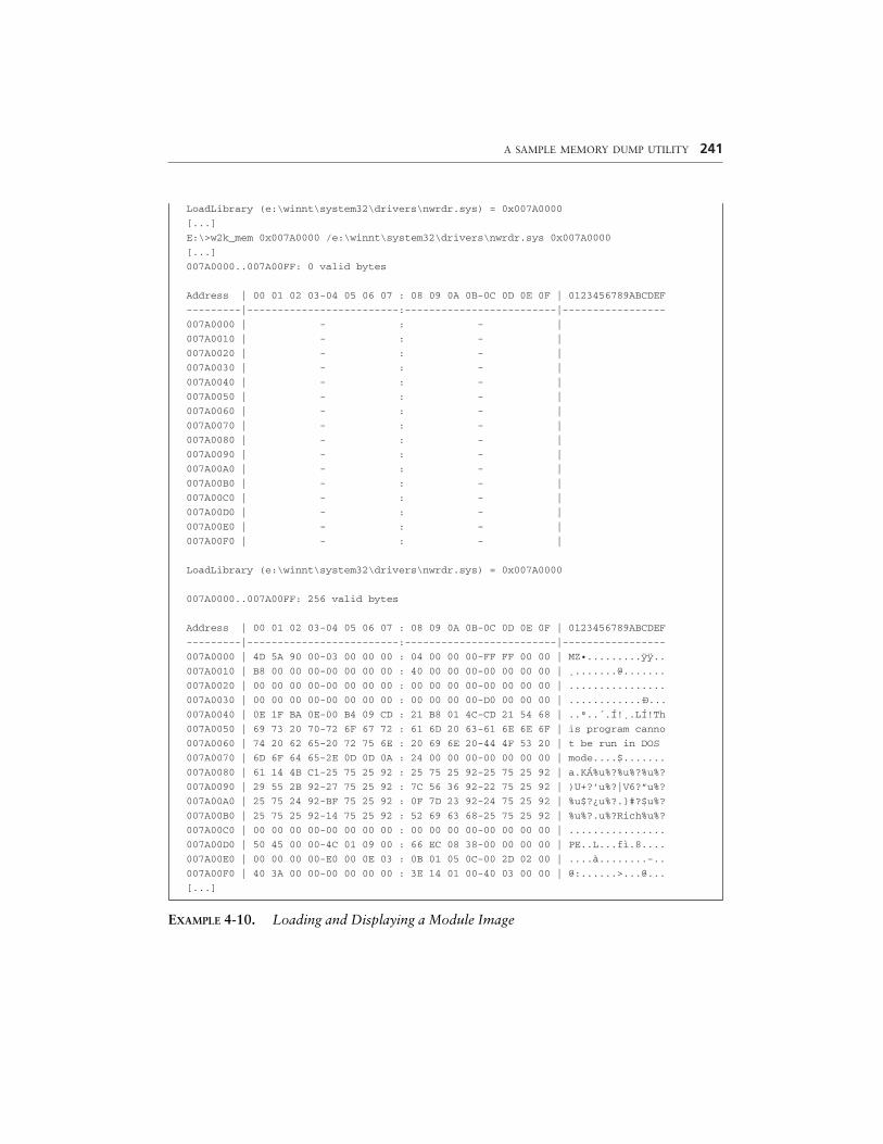
A SAMPLE MEMORY DUMP UTILITY 241
LoadLibrary (e:\winnt\system32\drivers\nwrdr.sys) = 0x007A0000
[...]
E:\>w2k_mem 0x007A0000 /e:\winnt\system32\drivers\nwrdr.sys 0x007A0000
[...]
007A0000..007A00FF: 0 valid bytes
Address | 00 01 02 03-04 05 06 07 : 08 09 0A 0B-0C 0D 0E 0F | 0123456789ABCDEF
---------|-------------------------:-------------------------|-----------------
007A0000 | - : - |
007A0010 | - : - |
007A0020 | - : - |
007A0030 | - : - |
007A0040 | - : - |
007A0050 | - : - |
007A0060 | - : - |
007A0070 | - : - |
007A0080 | - : - |
007A0090 | - : - |
007A00A0 | - : - |
007A00B0 | - : - |
007A00C0 | - : - |
007A00D0 | - : - |
007A00E0 | - : - |
007A00F0 | - : - |
LoadLibrary (e:\winnt\system32\drivers\nwrdr.sys) = 0x007A0000
007A0000..007A00FF: 256 valid bytes
Address | 00 01 02 03-04 05 06 07 : 08 09 0A 0B-0C 0D 0E 0F | 0123456789ABCDEF
---------|-------------------------:-------------------------|-----------------
007A0000 | 4D 5A 90 00-03 00 00 00 : 04 00 00 00-FF FF 00 00 | MZ•.........ÿÿ..
007A0010 | B8 00 00 00-00 00 00 00 : 40 00 00 00-00 00 00 00 | ¸.......@.......
007A0020 | 00 00 00 00-00 00 00 00 : 00 00 00 00-00 00 00 00 | ................
007A0030 | 00 00 00 00-00 00 00 00 : 00 00 00 00-D0 00 00 00 | ............–D...
007A0040 | 0E 1F BA 0E-00 B4 09 CD : 21 B8 01 4C-CD 21 54 68 | ..º..´.Í!¸.LÍ!Th
007A0050 | 69 73 20 70-72 6F 67 72 : 61 6D 20 63-61 6E 6E 6F | is program canno
007A0060 | 74 20 62 65-20 72 75 6E : 20 69 6E 20-44 4F 53 20 | t be run in DOS
007A0070 | 6D 6F 64 65-2E 0D 0D 0A : 24 00 00 00-00 00 00 00 | mode....$.......
007A0080 | 61 14 4B C1-25 75 25 92 : 25 75 25 92-25 75 25 92 | a.KÁ%u%?%u%?%u%?
007A0090 | 29 55 2B 92-27 75 25 92 : 7C 56 36 92-22 75 25 92 | )U+?’u%?|V6?”u%?
007A00A0 | 25 75 24 92-BF 75 25 92 : 0F 7D 23 92-24 75 25 92 | %u$?¿u%?.}#?$u%?
007A00B0 | 25 75 25 92-14 75 25 92 : 52 69 63 68-25 75 25 92 | %u%?.u%?Rich%u%?
007A00C0 | 00 00 00 00-00 00 00 00 : 00 00 00 00-00 00 00 00 | ................
007A00D0 | 50 45 00 00-4C 01 09 00 : 66 EC 08 38-00 00 00 00 | PE..L...fì.8....
007A00E0 | 00 00 00 00-E0 00 0E 03 : 0B 01 05 0C-00 2D 02 00 | ....à........-..
007A00F0 | 40 3A 00 00-00 00 00 00 : 3E 14 01 00-40 03 00 00 | @:......>...@...
[...]
EXAMPLE 4-10. Loading and Displaying a Module Image
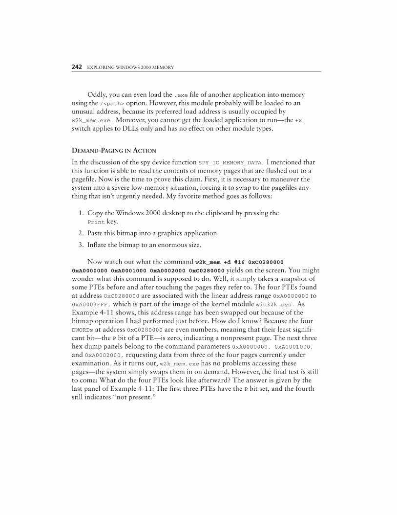
242 EXPLORING WINDOWS 2000 MEMORY
Oddly, you can even load the .exe file of another application into memoryusing the /<path> option. However, this module probably will be loaded to anunusual address, because its preferred load address is usually occupied byw2k_mem.exe. Moreover, you cannot get the loaded application to run—the +xswitch applies to DLLs only and has no effect on other module types.
DEMAND-PAGING IN ACTION
In the discussion of the spy device function SPY_IO_MEMORY_DATA, I mentioned thatthis function is able to read the contents of memory pages that are flushed out to apagefile. Now is the time to prove this claim. First, it is necessary to maneuver thesystem into a severe low-memory situation, forcing it to swap to the pagefiles any-thing that isn’t urgently needed. My favorite method goes as follows:
1. Copy the Windows 2000 desktop to the clipboard by pressing thePrint key.
2. Paste this bitmap into a graphics application.
3. Inflate the bitmap to an enormous size.
Now watch out what the command w2k_mem +d #16 0xC02800000xA0000000 0xA0001000 0xA0002000 0xC0280000 yields on the screen. You mightwonder what this command is supposed to do. Well, it simply takes a snapshot ofsome PTEs before and after touching the pages they refer to. The four PTEs foundat address 0xC0280000 are associated with the linear address range 0xA0000000 to0xA0003FFF, which is part of the image of the kernel module win32k.sys. AsExample 4-11 shows, this address range has been swapped out because of thebitmap operation I had performed just before. How do I know? Because the fourDWORDs at address 0xC0280000 are even numbers, meaning that their least signifi-cant bit—the P bit of a PTE—is zero, indicating a nonpresent page. The next threehex dump panels belong to the command parameters 0xA0000000, 0xA0001000,and 0xA0002000, requesting data from three of the four pages currently underexamination. As it turns out, w2k_mem.exe has no problems accessing thesepages—the system simply swaps them in on demand. However, the final test is stillto come: What do the four PTEs look like afterward? The answer is given by thelast panel of Example 4-11: The first three PTEs have the P bit set, and the fourthstill indicates “not present.”
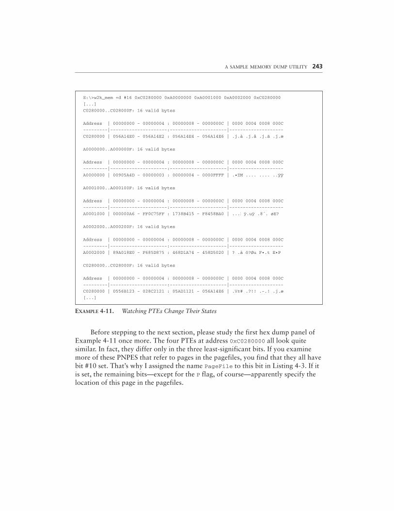
A SAMPLE MEMORY DUMP UTILITY 243
E:\>w2k_mem +d #16 0xC0280000 0xA0000000 0xA0001000 0xA0002000 0xC0280000
[...]
C0280000..C028000F: 16 valid bytes
Address | 00000000 - 00000004 : 00000008 - 0000000C | 0000 0004 0008 000C
---------|---------------------:---------------------|--------------------
C0280000 | 056A14E0 - 056A14E2 : 056A14E4 - 056A14E6 | .j.à .j.â .j.ä .j.æ
A0000000..A000000F: 16 valid bytes
Address | 00000000 - 00000004 : 00000008 - 0000000C | 0000 0004 0008 000C
---------|---------------------:---------------------|--------------------
A0000000 | 00905A4D - 00000003 : 00000004 - 0000FFFF | .•ZM .... .... ..ÿÿ
A0001000..A000100F: 16 valid bytes
Address | 00000000 - 00000004 : 00000008 - 0000000C | 0000 0004 0008 000C
---------|---------------------:---------------------|--------------------
A0001000 | 000000A6 - FF0C75FF : 1738B415 - F8458BA0 | ...|| ÿ.uÿ .8´. øE?
A0002000..A000200F: 16 valid bytes
Address | 00000000 - 00000004 : 00000008 - 0000000C | 0000 0004 0008 000C
---------|---------------------:---------------------|--------------------
A0002000 | 89A018E0 - F685D875 : 468D1A74 - 458D5020 | ? .à ö?Øu F•.t E•P
C0280000..C028000F: 16 valid bytes
Address | 00000000 - 00000004 : 00000008 - 0000000C | 0000 0004 0008 000C
---------|---------------------:---------------------|--------------------
C0280000 | 0556B123 - 028C2121 : 05AD1121 - 056A14E6 | .V±# .?!! .-.! .j.æ
[...]
EXAMPLE 4-11. Watching PTEs Change Their States
Before stepping to the next section, please study the first hex dump panel ofExample 4-11 once more. The four PTEs at address 0xC0280000 all look quitesimilar. In fact, they differ only in the three least-significant bits. If you examinemore of these PNPES that refer to pages in the pagefiles, you find that they all havebit #10 set. That’s why I assigned the name PageFile to this bit in Listing 4-3. If itis set, the remaining bits—except for the P flag, of course—apparently specify thelocation of this page in the pagefiles.
244 EXPLORING WINDOWS 2000 MEMORY
MORE COMMAND OPTIONS
Some of the most interesting command options listed in Example 4-1 have not yetbeen explained. For example the “System status options” +o, +c, +g, +i, and+b are missing, although they sound promising. I will return to them in the lastsection of this chapter, where several secrets of the Windows 2000 memory systemwill be revealed.
INTERFACING TO THE SPY DEVICE
Now that you know how w2k_mem.exe is used, it’s time to see how it works. Ratherthan discuss command line parsing and dispatching, let’s see how this applicationcommunicates with the spy device inside w2k_spy.sys.
DEVICE I/O CONTROL REVISITED
The kernel-mode side of IOCTL communication has already been shown in Listings4-6 and 4-7. The spy device simply sits waiting for I/O Request Packets (IRPs) andhandles some of them, especially those tagged IRP_MJ_DEVICE_CONTROL, whichrequest some forbidden actions to be executed, at least forbidden in the context ofthe user-mode application that sends these requests. It does so by calling the Win32API function DeviceIoControl(), prototyped in Listing 4-27. The dwIoControlCode,lpInBuffer, nInBufferSize, lpOutBuffer, nOutBufferSize, and lpBytesReturnedarguments should look familiar to you. In fact, they correspond 1:1 to the dCode,pInput, dInput, pOutput, dOutput, and pdInfo arguments of the SpyDispatcher()function in Listing 4-7. The remaining arguments are explained quickly. hDevice isthe handle to the spy device, and lpOverlapped optionally points to an OVERLAPPEDstructure required for asynchronous IOCTL. We are not going to send asynchronousrequests, so this argument will always be NULL.
Listing 4-28 is a collection of wrapper functions that perform basic IOCTLoperations. The most basic function is IoControl(), which calls DeviceIoControl()and tests the reported output data size. Because w2k_mem.exe sizes its output buffersaccurately, the number of output bytes should always be equal to the buffer size.ReadBinary() is a simplified version of IoControl() for IOCTL functions that don’trequire input data. ReadCpuInfo(), ReadSegment(), and ReadPhysical() arespecifically tailored to the spy functions SPY_IO_CPU_INFO, SPY_IO_SEGMENT, andSPY_IO_PHYSICAL, because these are the most frequently used IOCTL functions.Encapsulating them in C functions makes the code much more readable.
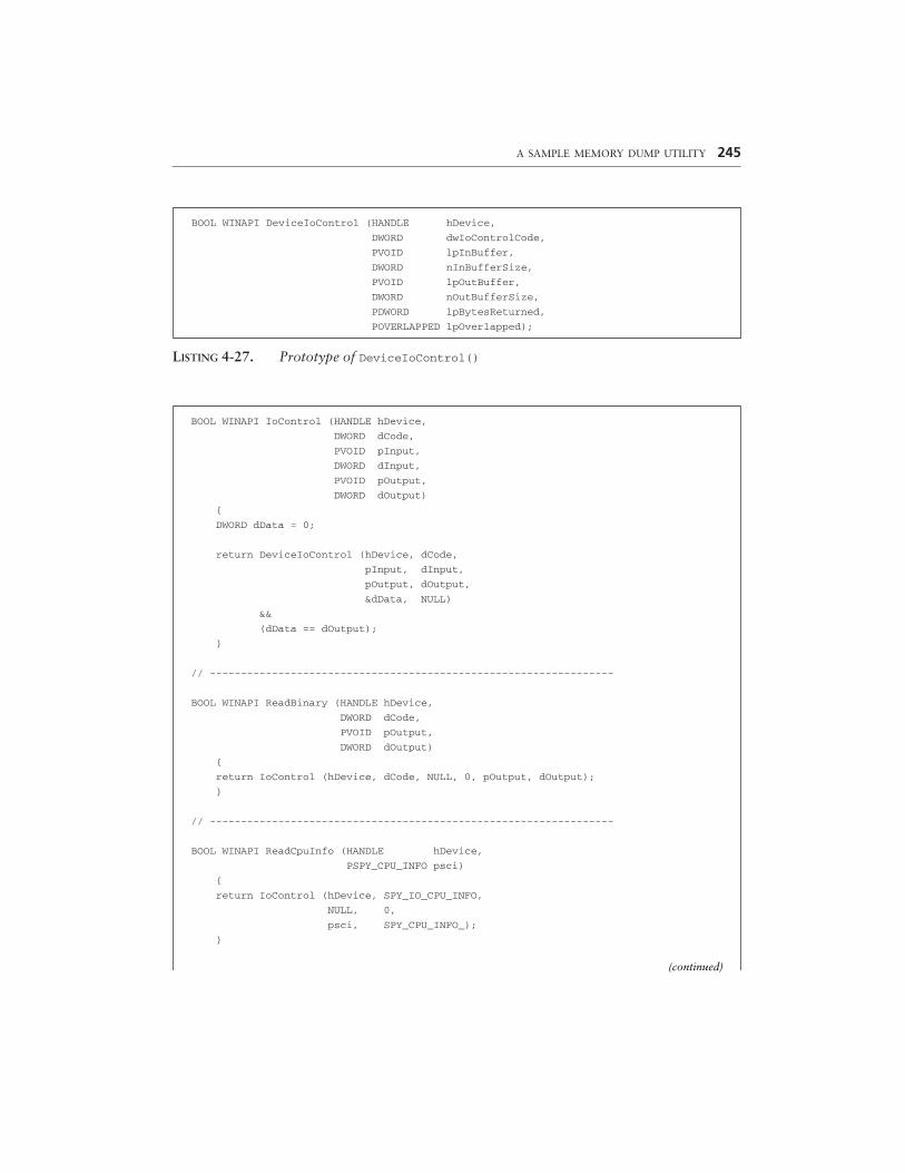
A SAMPLE MEMORY DUMP UTILITY 245
BOOL WINAPI DeviceIoControl (HANDLE hDevice,
DWORD dwIoControlCode,
PVOID lpInBuffer,
DWORD nInBufferSize,
PVOID lpOutBuffer,
DWORD nOutBufferSize,
PDWORD lpBytesReturned,
POVERLAPPED lpOverlapped);
LISTING 4-27. Prototype of DeviceIoControl()
BOOL WINAPI IoControl (HANDLE hDevice,
DWORD dCode,
PVOID pInput,
DWORD dInput,
PVOID pOutput,
DWORD dOutput)
{
DWORD dData = 0;
return DeviceIoControl (hDevice, dCode,
pInput, dInput,
pOutput, dOutput,
&dData, NULL)
&&
(dData == dOutput);
}
// -----------------------------------------------------------------
BOOL WINAPI ReadBinary (HANDLE hDevice,
DWORD dCode,
PVOID pOutput,
DWORD dOutput)
{
return IoControl (hDevice, dCode, NULL, 0, pOutput, dOutput);
}
// -----------------------------------------------------------------
BOOL WINAPI ReadCpuInfo (HANDLE hDevice,
PSPY_CPU_INFO psci)
{
return IoControl (hDevice, SPY_IO_CPU_INFO,
NULL, 0,
psci, SPY_CPU_INFO_);
}
(continued)
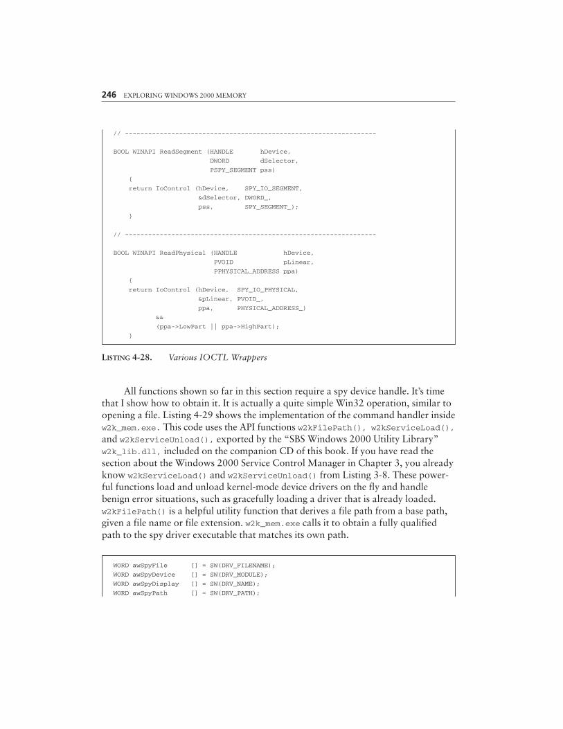
LISTING 4-28. Various IOCTL Wrappers
All functions shown so far in this section require a spy device handle. It’s timethat I show how to obtain it. It is actually a quite simple Win32 operation, similar toopening a file. Listing 4-29 shows the implementation of the command handler insidew2k_mem.exe. This code uses the API functions w2kFilePath(), w2kServiceLoad(),and w2kServiceUnload(), exported by the “SBS Windows 2000 Utility Library”w2k_lib.dll, included on the companion CD of this book. If you have read thesection about the Windows 2000 Service Control Manager in Chapter 3, you alreadyknow w2kServiceLoad() and w2kServiceUnload() from Listing 3-8. These power-ful functions load and unload kernel-mode device drivers on the fly and handlebenign error situations, such as gracefully loading a driver that is already loaded.w2kFilePath() is a helpful utility function that derives a file path from a base path,given a file name or file extension. w2k_mem.exe calls it to obtain a fully qualifiedpath to the spy driver executable that matches its own path.
246 EXPLORING WINDOWS 2000 MEMORY
// -----------------------------------------------------------------
BOOL WINAPI ReadSegment (HANDLE hDevice,
DWORD dSelector,
PSPY_SEGMENT pss)
{
return IoControl (hDevice, SPY_IO_SEGMENT,
&dSelector, DWORD_,
pss, SPY_SEGMENT_);
}
// -----------------------------------------------------------------
BOOL WINAPI ReadPhysical (HANDLE hDevice,
PVOID pLinear,
PPHYSICAL_ADDRESS ppa)
{
return IoControl (hDevice, SPY_IO_PHYSICAL,
&pLinear, PVOID_,
ppa, PHYSICAL_ADDRESS_)
&&
(ppa->LowPart || ppa->HighPart);
}
WORD awSpyFile [] = SW(DRV_FILENAME);
WORD awSpyDevice [] = SW(DRV_MODULE);
WORD awSpyDisplay [] = SW(DRV_NAME);
WORD awSpyPath [] = SW(DRV_PATH);
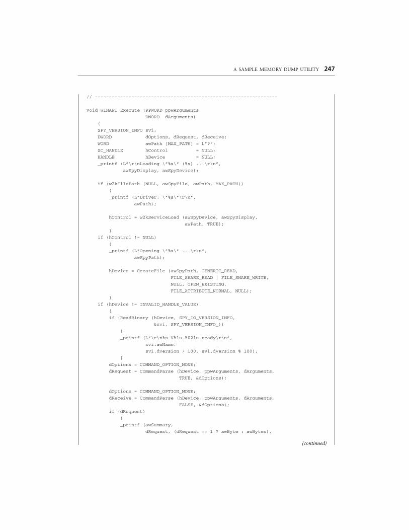
A SAMPLE MEMORY DUMP UTILITY 247
// -----------------------------------------------------------------
void WINAPI Execute (PPWORD ppwArguments,
DWORD dArguments)
{
SPY_VERSION_INFO svi;
DWORD dOptions, dRequest, dReceive;
WORD awPath [MAX_PATH] = L”?”;
SC_HANDLE hControl = NULL;
HANDLE hDevice = NULL;
_printf (L”\r\nLoading \”%s\” (%s) ...\r\n”,
awSpyDisplay, awSpyDevice);
if (w2kFilePath (NULL, awSpyFile, awPath, MAX_PATH))
{
_printf (L”Driver: \”%s\”\r\n”,
awPath);
hControl = w2kServiceLoad (awSpyDevice, awSpyDisplay,
awPath, TRUE);
}
if (hControl != NULL)
{
_printf (L”Opening \”%s\” ...\r\n”,
awSpyPath);
hDevice = CreateFile (awSpyPath, GENERIC_READ,
FILE_SHARE_READ | FILE_SHARE_WRITE,
NULL, OPEN_EXISTING,
FILE_ATTRIBUTE_NORMAL, NULL);
}
if (hDevice != INVALID_HANDLE_VALUE)
{
if (ReadBinary (hDevice, SPY_IO_VERSION_INFO,
&svi, SPY_VERSION_INFO_))
{
_printf (L”\r\n%s V%lu.%02lu ready\r\n”,
svi.awName,
svi.dVersion / 100, svi.dVersion % 100);
}
dOptions = COMMAND_OPTION_NONE;
dRequest = CommandParse (hDevice, ppwArguments, dArguments,
TRUE, &dOptions);
dOptions = COMMAND_OPTION_NONE;
dReceive = CommandParse (hDevice, ppwArguments, dArguments,
FALSE, &dOptions);
if (dRequest)
{
_printf (awSummary,
dRequest, (dRequest == 1 ? awByte : awBytes),
(continued)
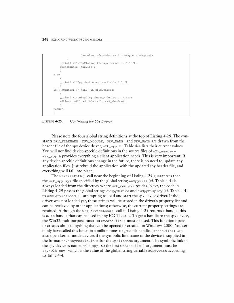
248 EXPLORING WINDOWS 2000 MEMORY
dReceive, (dReceive == 1 ? awByte : awBytes));
}
_printf (L”\r\nClosing the spy device ...\r\n”);
CloseHandle (hDevice);
}
else
{
_printf (L”Spy device not available.\r\n”);
}
if ((hControl != NULL) && gfSpyUnload)
{
_printf (L”Unloading the spy device ...\r\n”);
w2kServiceUnload (hControl, awSpyDevice);
}
return;
}
LISTING 4-29. Controlling the Spy Device
Please note the four global string definitions at the top of Listing 4-29. The con-stants DRV_FILENAME, DRV_MODULE, DRV_NAME, and DRV_PATH are drawn from theheader file of the spy device driver, w2k_spy.h. Table 4-4 lists their current values.You will not find device-specific definitions in the source files of w2k_mem.exe.w2k_spy.h provides everything a client application needs. This is very important: Ifany device-specific definitions change in the future, there is no need to update anyapplication files. Just rebuild the application with the updated spy header file, andeverything will fall into place.
The w2kFilePath() call near the beginning of Listing 4-29 guarantees thatthe w2k_spy.sys file specified by the global string awSpyFile (cf. Table 4-4) isalways loaded from the directory where w2k_mem.exe resides. Next, the code inListing 4-29 passes the global strings awSpyDevice and awSpyDisplay (cf. Table 4-4)to w2kServiceLoad(), attempting to load and start the spy device driver. If thedriver was not loaded yet, these strings will be stored in the driver’s property list andcan be retrieved by other applications; otherwise, the current property settings areretained. Although the w2kServiceLoad() call in Listing 4-29 returns a handle, thisis not a handle that can be used in any IOCTL calls. To get a handle to the spy device,the Win32 multipurpose function CreateFile() must be used. This function opensor creates almost anything that can be opened or created on Windows 2000. You cer-tainly have called this function a million times to get a file handle. CreateFile() canalso open kernel-mode devices if the symbolic link name of the device is supplied inthe format \\.\<SymbolicLink> for the lpFileName argument. The symbolic link ofthe spy device is named w2k_spy, so the first CreateFile() argument must be\\.\w2k_spy, which is the value of the global string variable awSpyPath accordingto Table 4-4.
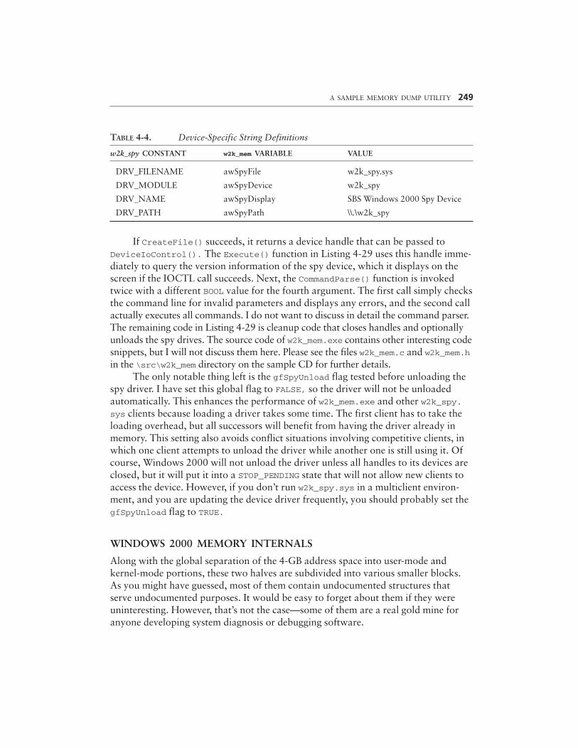
TABLE 4-4. Device-Specific String Definitions
w2k_spy CONSTANT w2k_mem VARIABLE VALUE
DRV_FILENAME awSpyFile w2k_spy.sys
DRV_MODULE awSpyDevice w2k_spy
DRV_NAME awSpyDisplay SBS Windows 2000 Spy Device
DRV_PATH awSpyPath \\.\w2k_spy
If CreateFile() succeeds, it returns a device handle that can be passed toDeviceIoControl(). The Execute() function in Listing 4-29 uses this handle imme-diately to query the version information of the spy device, which it displays on thescreen if the IOCTL call succeeds. Next, the CommandParse() function is invokedtwice with a different BOOL value for the fourth argument. The first call simply checksthe command line for invalid parameters and displays any errors, and the second callactually executes all commands. I do not want to discuss in detail the command parser.The remaining code in Listing 4-29 is cleanup code that closes handles and optionallyunloads the spy drives. The source code of w2k_mem.exe contains other interesting codesnippets, but I will not discuss them here. Please see the files w2k_mem.c and w2k_mem.hin the \src\w2k_mem directory on the sample CD for further details.
The only notable thing left is the gfSpyUnload flag tested before unloading thespy driver. I have set this global flag to FALSE, so the driver will not be unloadedautomatically. This enhances the performance of w2k_mem.exe and other w2k_spy.sys clients because loading a driver takes some time. The first client has to take theloading overhead, but all successors will benefit from having the driver already inmemory. This setting also avoids conflict situations involving competitive clients, inwhich one client attempts to unload the driver while another one is still using it. Ofcourse, Windows 2000 will not unload the driver unless all handles to its devices areclosed, but it will put it into a STOP_PENDING state that will not allow new clients toaccess the device. However, if you don’t run w2k_spy.sys in a multiclient environ-ment, and you are updating the device driver frequently, you should probably set thegfSpyUnload flag to TRUE.
WINDOWS 2000 MEMORY INTERNALS
Along with the global separation of the 4-GB address space into user-mode andkernel-mode portions, these two halves are subdivided into various smaller blocks.As you might have guessed, most of them contain undocumented structures thatserve undocumented purposes. It would be easy to forget about them if they wereuninteresting. However, that’s not the case—some of them are a real gold mine foranyone developing system diagnosis or debugging software.
A SAMPLE MEMORY DUMP UTILITY 249
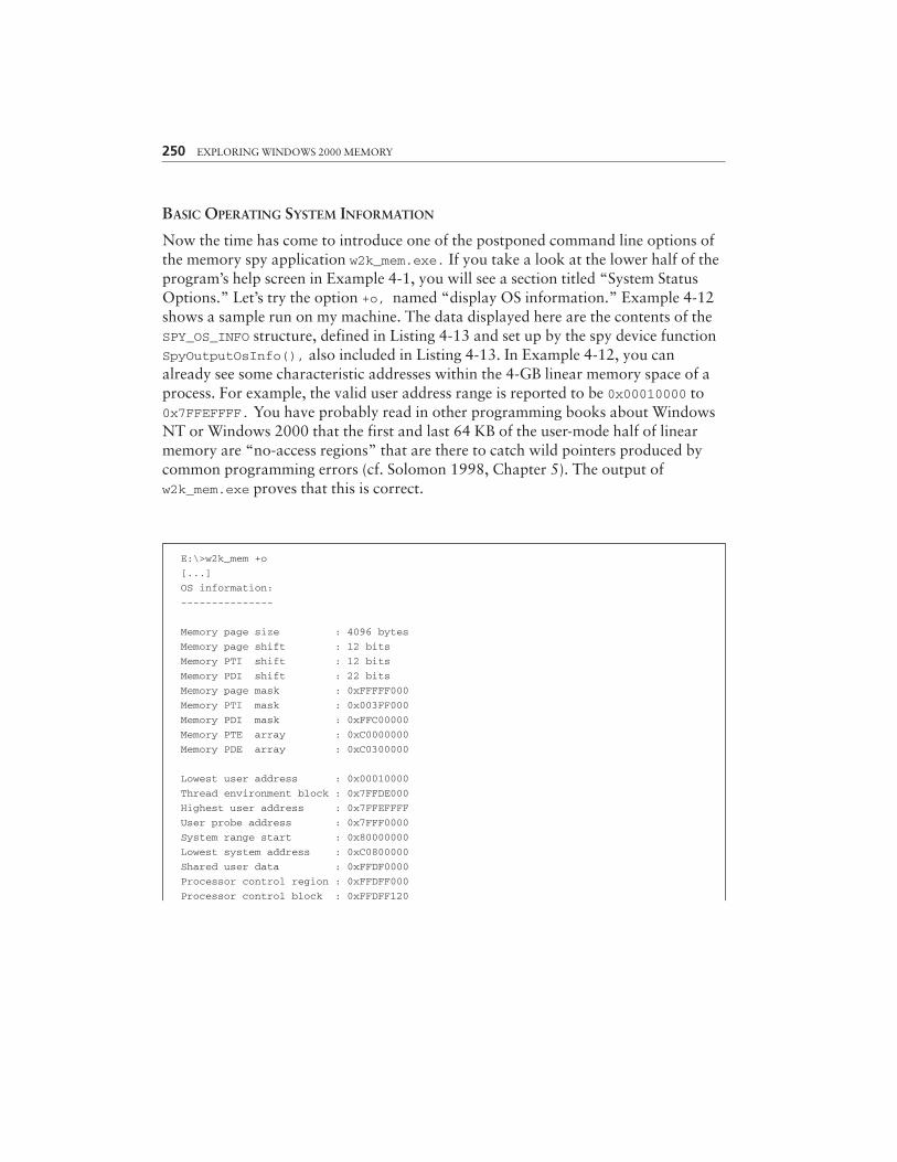
250 EXPLORING WINDOWS 2000 MEMORY
BASIC OPERATING SYSTEM INFORMATION
Now the time has come to introduce one of the postponed command line options ofthe memory spy application w2k_mem.exe. If you take a look at the lower half of theprogram’s help screen in Example 4-1, you will see a section titled “System StatusOptions.” Let’s try the option +o, named “display OS information.” Example 4-12shows a sample run on my machine. The data displayed here are the contents of theSPY_OS_INFO structure, defined in Listing 4-13 and set up by the spy device functionSpyOutputOsInfo(), also included in Listing 4-13. In Example 4-12, you canalready see some characteristic addresses within the 4-GB linear memory space of aprocess. For example, the valid user address range is reported to be 0x00010000 to0x7FFEFFFF. You have probably read in other programming books about WindowsNT or Windows 2000 that the first and last 64 KB of the user-mode half of linearmemory are “no-access regions” that are there to catch wild pointers produced bycommon programming errors (cf. Solomon 1998, Chapter 5). The output ofw2k_mem.exe proves that this is correct.
E:\>w2k_mem +o
[...]
OS information:
---------------
Memory page size : 4096 bytes
Memory page shift : 12 bits
Memory PTI shift : 12 bits
Memory PDI shift : 22 bits
Memory page mask : 0xFFFFF000
Memory PTI mask : 0x003FF000
Memory PDI mask : 0xFFC00000
Memory PTE array : 0xC0000000
Memory PDE array : 0xC0300000
Lowest user address : 0x00010000
Thread environment block : 0x7FFDE000
Highest user address : 0x7FFEFFFF
User probe address : 0x7FFF0000
System range start : 0x80000000
Lowest system address : 0xC0800000
Shared user data : 0xFFDF0000
Processor control region : 0xFFDFF000
Processor control block : 0xFFDFF120
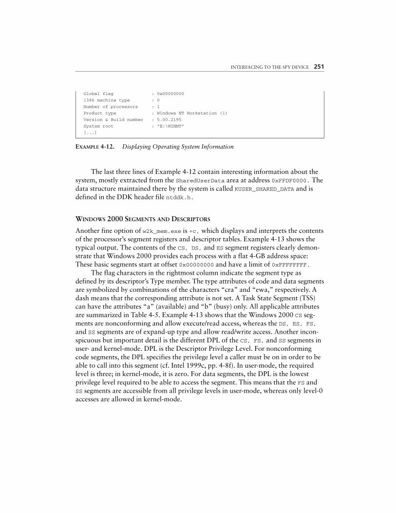
INTERFACING TO THE SPY DEVICE 251
Global flag : 0x00000000
i386 machine type : 0
Number of processors : 1
Product type : Windows NT Workstation (1)
Version & Build number : 5.00.2195
System root : “E:\WINNT”
[...]
EXAMPLE 4-12. Displaying Operating System Information
The last three lines of Example 4-12 contain interesting information about thesystem, mostly extracted from the SharedUserData area at address 0xFFDF0000. Thedata structure maintained there by the system is called KUSER_SHARED_DATA and isdefined in the DDK header file ntddk.h.
WINDOWS 2000 SEGMENTS AND DESCRIPTORS
Another fine option of w2k_mem.exe is +c, which displays and interprets the contentsof the processor’s segment registers and descriptor tables. Example 4-13 shows thetypical output. The contents of the CS, DS, and ES segment registers clearly demon-strate that Windows 2000 provides each process with a flat 4-GB address space:These basic segments start at offset 0x00000000 and have a limit of 0xFFFFFFFF.
The flag characters in the rightmost column indicate the segment type asdefined by its descriptor’s Type member. The type attributes of code and data segmentsare symbolized by combinations of the characters “cra” and “ewa,” respectively. Adash means that the corresponding attribute is not set. A Task State Segment (TSS)can have the attributes “a” (available) and “b” (busy) only. All applicable attributesare summarized in Table 4-5. Example 4-13 shows that the Windows 2000 CS seg-ments are nonconforming and allow execute/read access, whereas the DS, ES, FS,and SS segments are of expand-up type and allow read/write access. Another incon-spicuous but important detail is the different DPL of the CS, FS, and SS segments inuser- and kernel-mode. DPL is the Descriptor Privilege Level. For nonconformingcode segments, the DPL specifies the privilege level a caller must be on in order to beable to call into this segment (cf. Intel 1999c, pp. 4-8f). In user-mode, the requiredlevel is three; in kernel-mode, it is zero. For data segments, the DPL is the lowestprivilege level required to be able to access the segment. This means that the FS andSS segments are accessible from all privilege levels in user-mode, whereas only level-0accesses are allowed in kernel-mode.

252 EXPLORING WINDOWS 2000 MEMORY
E:\>w2k_mem +c
[...]
CPU information:
----------------
User mode segments:
CS : Selector = 001B, Base = 00000000, Limit = FFFFFFFF, DPL3, Type = CODE -ra
DS : Selector = 0023, Base = 00000000, Limit = FFFFFFFF, DPL3, Type = DATA -wa
ES : Selector = 0023, Base = 00000000, Limit = FFFFFFFF, DPL3, Type = DATA -wa
FS : Selector = 0038, Base = 7FFDE000, Limit = 00000FFF, DPL3, Type = DATA -wa
SS : Selector = 0023, Base = 00000000, Limit = FFFFFFFF, DPL3, Type = DATA -wa
TSS : Selector = 0028, Base = 80244000, Limit = 000020AB, DPL0, Type = TSS32 b
Kernel mode segments:
CS : Selector = 0008, Base = 00000000, Limit = FFFFFFFF, DPL0, Type = CODE -ra
DS : Selector = 0023, Base = 00000000, Limit = FFFFFFFF, DPL3, Type = DATA -wa
ES : Selector = 0023, Base = 00000000, Limit = FFFFFFFF, DPL3, Type = DATA -wa
FS : Selector = 0030, Base = FFDFF000, Limit = 00001FFF, DPL0, Type = DATA -wa
SS : Selector = 0010, Base = 00000000, Limit = FFFFFFFF, DPL0, Type = DATA -wa
TSS : Selector = 0028, Base = 80244000, Limit = 000020AB, DPL0, Type = TSS32 b
IDT : Limit = 07FF, Base = 80036400
GDT : Limit = 03FF, Base = 80036000
LDT : Selector = 0000
CR0 : Contents = 8001003B
CR2 : Contents = 00401050
CR3 : Contents = 06F70000
[...]
EXAMPLE 4-13. Displaying CPU Information
The contents of the IDT and GDT registers show that the GDT spans from lin-ear address 0x80036000 to 800363FF, immediately followed by the IDT, occupyingthe address range 0x80036400 to 0x80036BFF. With each descriptor taking 64 bits,the GDT and IDT contain 128 and 256 entries, respectively. Note that the GDTcould comprise as many as 8,192 entries, but Windows 2000 uses only a small frac-tion of them.
The w2k_mem.exe utility features two more options—+g and +i—that displaymore details about the GDT and IDT. Example 4-14 demonstrates the output of the+g option. It is similar to the “kernel-mode segments:” section of Example 4-13, butlists all segment selectors available in kernel-mode, not just those that are stored insegment registers. w2k_mem.exe compiles this list by looping through the entire GDT,
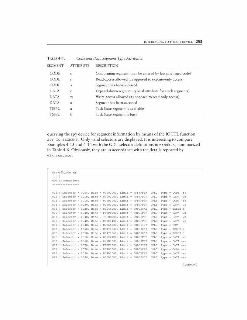
INTERFACING TO THE SPY DEVICE 253
TABLE 4-5. Code and Data Segment Type Attributes
SEGMENT ATTRIBUTE DESCRIPTION
CODE c Conforming segment (may be entered by less privileged code)
CODE r Read-access allowed (as opposed to execute-only access)
CODE a Segment has been accessed
DATA e Expand-down segment (typical attribute for stack segments)
DATA w Write-access allowed (as opposed to read-only access)
DATA a Segment has been accessed
TSS32 a Task State Segment is available
TSS32 b Task State Segment is busy
querying the spy device for segment information by means of the IOCTL functionSPY_IO_SEGMENT. Only valid selectors are displayed. It is interesting to compareExamples 4-13 and 4-14 with the GDT selector definitions in ntddk.h, summarizedin Table 4-6. Obviously, they are in accordance with the details reported byw2k_mem.exe.
E:\>w2k_mem +g
[...]
GDT information:
----------------
001 : Selector = 0008, Base = 00000000, Limit = FFFFFFFF, DPL0, Type = CODE -ra
002 : Selector = 0010, Base = 00000000, Limit = FFFFFFFF, DPL0, Type = DATA -wa
003 : Selector = 0018, Base = 00000000, Limit = FFFFFFFF, DPL3, Type = CODE -ra
004 : Selector = 0020, Base = 00000000, Limit = FFFFFFFF, DPL3, Type = DATA -wa
005 : Selector = 0028, Base = 80244000, Limit = 000020AB, DPL0, Type = TSS32 b
006 : Selector = 0030, Base = FFDFF000, Limit = 00001FFF, DPL0, Type = DATA -wa
007 : Selector = 0038, Base = 7FFDE000, Limit = 00000FFF, DPL3, Type = DATA -wa
008 : Selector = 0040, Base = 00000400, Limit = 0000FFFF, DPL3, Type = DATA -wa
009 : Selector = 0048, Base = E2E6A000, Limit = 00000177, DPL0, Type = LDT
00A : Selector = 0050, Base = 80470040, Limit = 00000068, DPL0, Type = TSS32 a
00B : Selector = 0058, Base = 804700A8, Limit = 00000068, DPL0, Type = TSS32 a
00C : Selector = 0060, Base = 00022AB0, Limit = 0000FFFF, DPL0, Type = DATA -wa
00D : Selector = 0068, Base = 000B8000, Limit = 00003FFF, DPL0, Type = DATA -w-
00E : Selector = 0070, Base = FFFF7000, Limit = 000003FF, DPL0, Type = DATA -w-
00F : Selector = 0078, Base = 80400000, Limit = 0000FFFF, DPL0, Type = CODE -r-
010 : Selector = 0080, Base = 80400000, Limit = 0000FFFF, DPL0, Type = DATA -w-
011 : Selector = 0088, Base = 00000000, Limit = 00000000, DPL0, Type = DATA -w-
(continued)
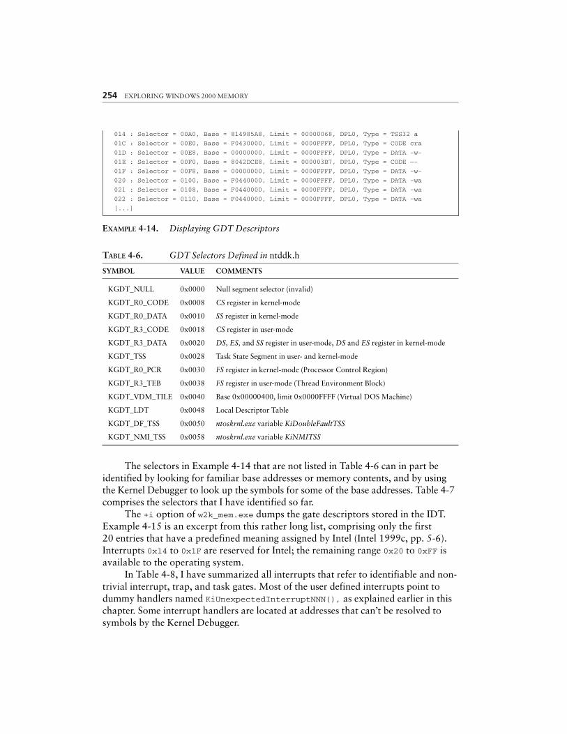
254 EXPLORING WINDOWS 2000 MEMORY
014 : Selector = 00A0, Base = 814985A8, Limit = 00000068, DPL0, Type = TSS32 a
01C : Selector = 00E0, Base = F0430000, Limit = 0000FFFF, DPL0, Type = CODE cra
01D : Selector = 00E8, Base = 00000000, Limit = 0000FFFF, DPL0, Type = DATA -w-
01E : Selector = 00F0, Base = 8042DCE8, Limit = 000003B7, DPL0, Type = CODE —-
01F : Selector = 00F8, Base = 00000000, Limit = 0000FFFF, DPL0, Type = DATA -w-
020 : Selector = 0100, Base = F0440000, Limit = 0000FFFF, DPL0, Type = DATA -wa
021 : Selector = 0108, Base = F0440000, Limit = 0000FFFF, DPL0, Type = DATA -wa
022 : Selector = 0110, Base = F0440000, Limit = 0000FFFF, DPL0, Type = DATA –wa
[...]
EXAMPLE 4-14. Displaying GDT Descriptors
TABLE 4-6. GDT Selectors Defined in ntddk.h
SYMBOL VALUE COMMENTS
KGDT_NULL 0x0000 Null segment selector (invalid)
KGDT_R0_CODE 0x0008 CS register in kernel-mode
KGDT_R0_DATA 0x0010 SS register in kernel-mode
KGDT_R3_CODE 0x0018 CS register in user-mode
KGDT_R3_DATA 0x0020 DS, ES, and SS register in user-mode, DS and ES register in kernel-mode
KGDT_TSS 0x0028 Task State Segment in user- and kernel-mode
KGDT_R0_PCR 0x0030 FS register in kernel-mode (Processor Control Region)
KGDT_R3_TEB 0x0038 FS register in user-mode (Thread Environment Block)
KGDT_VDM_TILE 0x0040 Base 0x00000400, limit 0x0000FFFF (Virtual DOS Machine)
KGDT_LDT 0x0048 Local Descriptor Table
KGDT_DF_TSS 0x0050 ntoskrnl.exe variable KiDoubleFaultTSS
KGDT_NMI_TSS 0x0058 ntoskrnl.exe variable KiNMITSS
The selectors in Example 4-14 that are not listed in Table 4-6 can in part beidentified by looking for familiar base addresses or memory contents, and by usingthe Kernel Debugger to look up the symbols for some of the base addresses. Table 4-7comprises the selectors that I have identified so far.
The +i option of w2k_mem.exe dumps the gate descriptors stored in the IDT.Example 4-15 is an excerpt from this rather long list, comprising only the first20 entries that have a predefined meaning assigned by Intel (Intel 1999c, pp. 5-6).Interrupts 0x14 to 0x1F are reserved for Intel; the remaining range 0x20 to 0xFF isavailable to the operating system.
In Table 4-8, I have summarized all interrupts that refer to identifiable and non-trivial interrupt, trap, and task gates. Most of the user defined interrupts point todummy handlers named KiUnexpectedInterruptNNN(), as explained earlier in thischapter. Some interrupt handlers are located at addresses that can’t be resolved tosymbols by the Kernel Debugger.
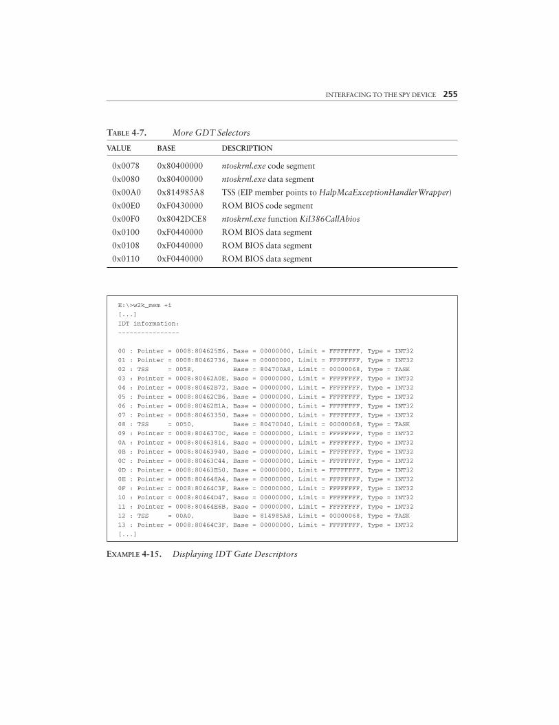
INTERFACING TO THE SPY DEVICE 255
TABLE 4-7. More GDT Selectors
VALUE BASE DESCRIPTION
0x0078 0x80400000 ntoskrnl.exe code segment
0x0080 0x80400000 ntoskrnl.exe data segment
0x00A0 0x814985A8 TSS (EIP member points to HalpMcaExceptionHandlerWrapper)
0x00E0 0xF0430000 ROM BIOS code segment
0x00F0 0x8042DCE8 ntoskrnl.exe function KiI386CallAbios
0x0100 0xF0440000 ROM BIOS data segment
0x0108 0xF0440000 ROM BIOS data segment
0x0110 0xF0440000 ROM BIOS data segment
E:\>w2k_mem +i
[...]
IDT information:
----------------
00 : Pointer = 0008:804625E6, Base = 00000000, Limit = FFFFFFFF, Type = INT32
01 : Pointer = 0008:80462736, Base = 00000000, Limit = FFFFFFFF, Type = INT32
02 : TSS = 0058, Base = 804700A8, Limit = 00000068, Type = TASK
03 : Pointer = 0008:80462A0E, Base = 00000000, Limit = FFFFFFFF, Type = INT32
04 : Pointer = 0008:80462B72, Base = 00000000, Limit = FFFFFFFF, Type = INT32
05 : Pointer = 0008:80462CB6, Base = 00000000, Limit = FFFFFFFF, Type = INT32
06 : Pointer = 0008:80462E1A, Base = 00000000, Limit = FFFFFFFF, Type = INT32
07 : Pointer = 0008:80463350, Base = 00000000, Limit = FFFFFFFF, Type = INT32
08 : TSS = 0050, Base = 80470040, Limit = 00000068, Type = TASK
09 : Pointer = 0008:8046370C, Base = 00000000, Limit = FFFFFFFF, Type = INT32
0A : Pointer = 0008:80463814, Base = 00000000, Limit = FFFFFFFF, Type = INT32
0B : Pointer = 0008:80463940, Base = 00000000, Limit = FFFFFFFF, Type = INT32
0C : Pointer = 0008:80463C44, Base = 00000000, Limit = FFFFFFFF, Type = INT32
0D : Pointer = 0008:80463E50, Base = 00000000, Limit = FFFFFFFF, Type = INT32
0E : Pointer = 0008:804648A4, Base = 00000000, Limit = FFFFFFFF, Type = INT32
0F : Pointer = 0008:80464C3F, Base = 00000000, Limit = FFFFFFFF, Type = INT32
10 : Pointer = 0008:80464D47, Base = 00000000, Limit = FFFFFFFF, Type = INT32
11 : Pointer = 0008:80464E6B, Base = 00000000, Limit = FFFFFFFF, Type = INT32
12 : TSS = 00A0, Base = 814985A8, Limit = 00000068, Type = TASK
13 : Pointer = 0008:80464C3F, Base = 00000000, Limit = FFFFFFFF, Type = INT32
[...]
EXAMPLE 4-15. Displaying IDT Gate Descriptors
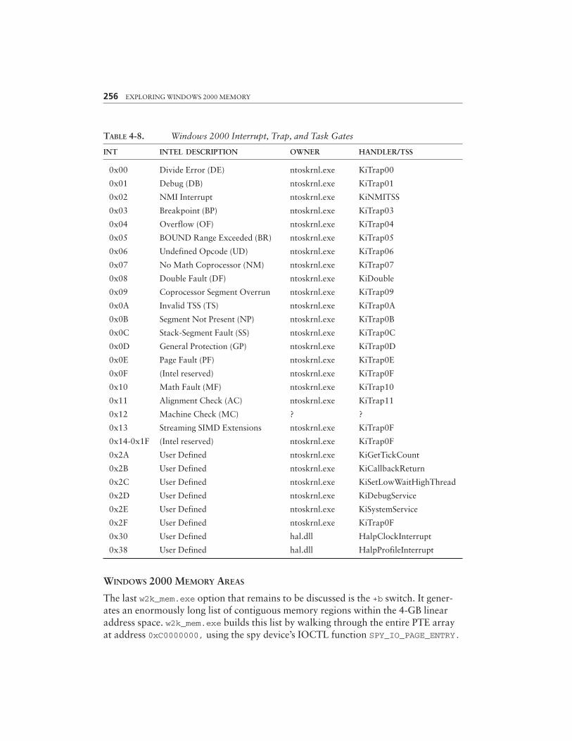
TABLE 4-8. Windows 2000 Interrupt, Trap, and Task Gates
INT INTEL DESCRIPTION OWNER HANDLER/TSS
0x00 Divide Error (DE) ntoskrnl.exe KiTrap00
0x01 Debug (DB) ntoskrnl.exe KiTrap01
0x02 NMI Interrupt ntoskrnl.exe KiNMITSS
0x03 Breakpoint (BP) ntoskrnl.exe KiTrap03
0x04 Overflow (OF) ntoskrnl.exe KiTrap04
0x05 BOUND Range Exceeded (BR) ntoskrnl.exe KiTrap05
0x06 Undefined Opcode (UD) ntoskrnl.exe KiTrap06
0x07 No Math Coprocessor (NM) ntoskrnl.exe KiTrap07
0x08 Double Fault (DF) ntoskrnl.exe KiDouble
0x09 Coprocessor Segment Overrun ntoskrnl.exe KiTrap09
0x0A Invalid TSS (TS) ntoskrnl.exe KiTrap0A
0x0B Segment Not Present (NP) ntoskrnl.exe KiTrap0B
0x0C Stack-Segment Fault (SS) ntoskrnl.exe KiTrap0C
0x0D General Protection (GP) ntoskrnl.exe KiTrap0D
0x0E Page Fault (PF) ntoskrnl.exe KiTrap0E
0x0F (Intel reserved) ntoskrnl.exe KiTrap0F
0x10 Math Fault (MF) ntoskrnl.exe KiTrap10
0x11 Alignment Check (AC) ntoskrnl.exe KiTrap11
0x12 Machine Check (MC) ? ?
0x13 Streaming SIMD Extensions ntoskrnl.exe KiTrap0F
0x14-0x1F (Intel reserved) ntoskrnl.exe KiTrap0F
0x2A User Defined ntoskrnl.exe KiGetTickCount
0x2B User Defined ntoskrnl.exe KiCallbackReturn
0x2C User Defined ntoskrnl.exe KiSetLowWaitHighThread
0x2D User Defined ntoskrnl.exe KiDebugService
0x2E User Defined ntoskrnl.exe KiSystemService
0x2F User Defined ntoskrnl.exe KiTrap0F
0x30 User Defined hal.dll HalpClockInterrupt
0x38 User Defined hal.dll HalpProfileInterrupt
WINDOWS 2000 MEMORY AREAS
The last w2k_mem.exe option that remains to be discussed is the +b switch. It gener-ates an enormously long list of contiguous memory regions within the 4-GB linearaddress space. w2k_mem.exe builds this list by walking through the entire PTE arrayat address 0xC0000000, using the spy device’s IOCTL function SPY_IO_PAGE_ENTRY.
256 EXPLORING WINDOWS 2000 MEMORY
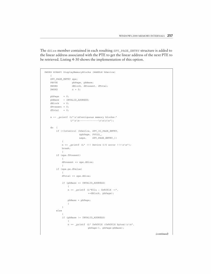
The dSize member contained in each resulting SPY_PAGE_ENTRY structure is added tothe linear address associated with the PTE to get the linear address of the next PTE tobe retrieved. Listing 4-30 shows the implementation of this option.
WINDOWS 2000 MEMORY INTERNALS 257
DWORD WINAPI DisplayMemoryBlocks (HANDLE hDevice)
{
SPY_PAGE_ENTRY spe;
PBYTE pbPage, pbBase;
DWORD dBlock, dPresent, dTotal;
DWORD n = 0;
pbPage = 0;
pbBase = INVALID_ADDRESS;
dBlock = 0;
dPresent = 0;
dTotal = 0;
n += _printf (L”\r\nContiguous memory blocks:”
L”\r\n-------------\r\n\r\n”);
do {
if (!IoControl (hDevice, SPY_IO_PAGE_ENTRY,
&pbPage, PVOID_,
&spe, SPY_PAGE_ENTRY_))
{
n += _printf (L” !!! Device I/O error !!!\r\n”);
break;
}
if (spe.fPresent)
{
dPresent += spe.dSize;
}
if (spe.pe.dValue)
{
dTotal += spe.dSize;
if (pbBase == INVALID_ADDRESS)
{
n += _printf (L”%5lu : 0x%08lX ->”,
++dBlock, pbPage);
pbBase = pbPage;
}
}
else
{
if (pbBase != INVALID_ADDRESS)
{
n += _printf (L” 0x%08lX (0x%08lX bytes)\r\n”,
pbPage-1, pbPage-pbBase);
(continued)

258 EXPLORING WINDOWS 2000 MEMORY
pbBase = INVALID_ADDRESS;
}
}
}
while (pbPage += spe.Size);
if (pbBase != INVALID_ADDRESS)
{
n += _printf (L”0x%08lX\r\n”, pbPage-1);
}
n += _printf (L”\r\n”
L” Present bytes: 0x%08lX\r\n”
L” Total bytes: 0x%08lX\r\n”,
dPresent, dTotal);
return n;
}
LISTING 4-30. Finding Contiguous Linear Memory Blocks
Example 4-16 is an excerpt from a sample run on my machine, showing someof the more interesting regions. Some very obvious addresses are 0x00400000, wherethe image of w2k_mem.exe starts (block #13), and 0x10000000, where the image ofw2k_lib.dll is located (block #23). The TEB and PEB pages also are clearly dis-cernible (block #104), as are the hal.dll, ntoskrnl.exe, and win32k.sys areas(blocks #105 and 106). Blocks #340 to 350 are, of course, the valid fragments of thesystem’s PTE array, featuring the page-directory as part of block #347. Block #2122contains the SharedUserData area, and #2123 comprises the KPCR, KPRCB, andCONTEXT structures containing thread and processor status information.
E:\>w2k_mem +b[...]
Contiguous memory blocks:
-------------------------
1 : 0x00010000 -> 0x00010FFF (0x00001000 bytes)
2 : 0x00020000 -> 0x00020FFF (0x00001000 bytes)
3 : 0x0012D000 -> 0x00138FFF (0x0000C000 bytes)
4 : 0x00230000 -> 0x00230FFF (0x00001000 bytes)
5 : 0x00240000 -> 0x00241FFF (0x00002000 bytes)
6 : 0x00247000 -> 0x00247FFF (0x00001000 bytes)
7 : 0x0024F000 -> 0x00250FFF (0x00002000 bytes)
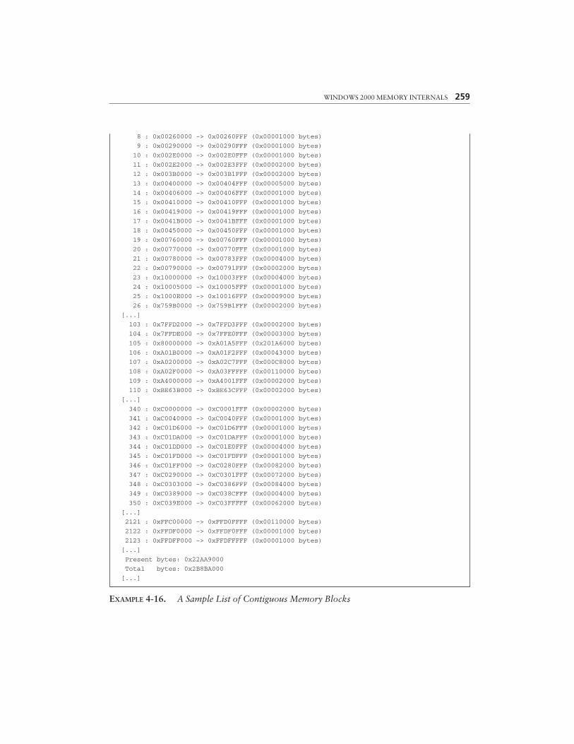
WINDOWS 2000 MEMORY INTERNALS 259
8 : 0x00260000 -> 0x00260FFF (0x00001000 bytes)
9 : 0x00290000 -> 0x00290FFF (0x00001000 bytes)
10 : 0x002E0000 -> 0x002E0FFF (0x00001000 bytes)
11 : 0x002E2000 -> 0x002E3FFF (0x00002000 bytes)
12 : 0x003B0000 -> 0x003B1FFF (0x00002000 bytes)
13 : 0x00400000 -> 0x00404FFF (0x00005000 bytes)
14 : 0x00406000 -> 0x00406FFF (0x00001000 bytes)
15 : 0x00410000 -> 0x00410FFF (0x00001000 bytes)
16 : 0x00419000 -> 0x00419FFF (0x00001000 bytes)
17 : 0x0041B000 -> 0x0041BFFF (0x00001000 bytes)
18 : 0x00450000 -> 0x00450FFF (0x00001000 bytes)
19 : 0x00760000 -> 0x00760FFF (0x00001000 bytes)
20 : 0x00770000 -> 0x00770FFF (0x00001000 bytes)
21 : 0x00780000 -> 0x00783FFF (0x00004000 bytes)
22 : 0x00790000 -> 0x00791FFF (0x00002000 bytes)
23 : 0x10000000 -> 0x10003FFF (0x00004000 bytes)
24 : 0x10005000 -> 0x10005FFF (0x00001000 bytes)
25 : 0x1000E000 -> 0x10016FFF (0x00009000 bytes)
26 : 0x759B0000 -> 0x759B1FFF (0x00002000 bytes)
[...]
103 : 0x7FFD2000 -> 0x7FFD3FFF (0x00002000 bytes)
104 : 0x7FFDE000 -> 0x7FFE0FFF (0x00003000 bytes)
105 : 0x80000000 -> 0xA01A5FFF (0x201A6000 bytes)
106 : 0xA01B0000 -> 0xA01F2FFF (0x00043000 bytes)
107 : 0xA0200000 -> 0xA02C7FFF (0x000C8000 bytes)
108 : 0xA02F0000 -> 0xA03FFFFF (0x00110000 bytes)
109 : 0xA4000000 -> 0xA4001FFF (0x00002000 bytes)
110 : 0xBE63B000 -> 0xBE63CFFF (0x00002000 bytes)
[...]
340 : 0xC0000000 -> 0xC0001FFF (0x00002000 bytes)
341 : 0xC0040000 -> 0xC0040FFF (0x00001000 bytes)
342 : 0xC01D6000 -> 0xC01D6FFF (0x00001000 bytes)
343 : 0xC01DA000 -> 0xC01DAFFF (0x00001000 bytes)
344 : 0xC01DD000 -> 0xC01E0FFF (0x00004000 bytes)
345 : 0xC01FD000 -> 0xC01FDFFF (0x00001000 bytes)
346 : 0xC01FF000 -> 0xC0280FFF (0x00082000 bytes)
347 : 0xC0290000 -> 0xC0301FFF (0x00072000 bytes)
348 : 0xC0303000 -> 0xC0386FFF (0x00084000 bytes)
349 : 0xC0389000 -> 0xC038CFFF (0x00004000 bytes)
350 : 0xC039E000 -> 0xC03FFFFF (0x00062000 bytes)
[...]
2121 : 0xFFC00000 -> 0xFFD0FFFF (0x00110000 bytes)
2122 : 0xFFDF0000 -> 0xFFDF0FFF (0x00001000 bytes)
2123 : 0xFFDFF000 -> 0xFFDFFFFF (0x00001000 bytes)
[...]
Present bytes: 0x22AA9000
Total bytes: 0x2B8BA000
[...]
EXAMPLE 4-16. A Sample List of Contiguous Memory Blocks
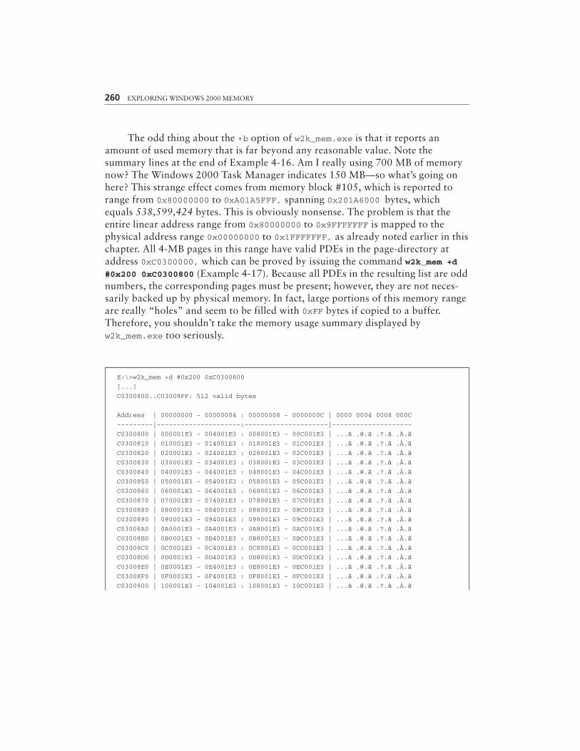
260 EXPLORING WINDOWS 2000 MEMORY
The odd thing about the +b option of w2k_mem.exe is that it reports anamount of used memory that is far beyond any reasonable value. Note thesummary lines at the end of Example 4-16. Am I really using 700 MB of memorynow? The Windows 2000 Task Manager indicates 150 MB—so what’s going onhere? This strange effect comes from memory block #105, which is reported torange from 0x80000000 to 0xA01A5FFF, spanning 0x201A6000 bytes, whichequals 538,599,424 bytes. This is obviously nonsense. The problem is that theentire linear address range from 0x80000000 to 0x9FFFFFFF is mapped to thephysical address range 0x00000000 to 0x1FFFFFFF, as already noted earlier in thischapter. All 4-MB pages in this range have valid PDEs in the page-directory ataddress 0xC0300000, which can be proved by issuing the command w2k_mem +d#0x200 0xC0300800 (Example 4-17). Because all PDEs in the resulting list are oddnumbers, the corresponding pages must be present; however, they are not neces-sarily backed up by physical memory. In fact, large portions of this memory rangeare really “holes” and seem to be filled with 0xFF bytes if copied to a buffer.Therefore, you shouldn’t take the memory usage summary displayed byw2k_mem.exe too seriously.
E:\>w2k_mem +d #0x200 0xC0300800
[...]
C0300800..C03009FF: 512 valid bytes
Address | 00000000 - 00000004 : 00000008 - 0000000C | 0000 0004 0008 000C
---------|---------------------:---------------------|--------------------
C0300800 | 000001E3 - 004001E3 : 008001E3 - 00C001E3 | ...ã .@.ã .?.ã .À.ã
C0300810 | 010001E3 - 014001E3 : 018001E3 - 01C001E3 | ...ã .@.ã .?.ã .À.ã
C0300820 | 020001E3 - 024001E3 : 028001E3 - 02C001E3 | ...ã .@.ã .?.ã .À.ã
C0300830 | 030001E3 - 034001E3 : 038001E3 - 03C001E3 | ...ã .@.ã .?.ã .À.ã
C0300840 | 040001E3 - 044001E3 : 048001E3 - 04C001E3 | ...ã .@.ã .?.ã .À.ã
C0300850 | 050001E3 - 054001E3 : 058001E3 - 05C001E3 | ...ã .@.ã .?.ã .À.ã
C0300860 | 060001E3 - 064001E3 : 068001E3 - 06C001E3 | ...ã .@.ã .?.ã .À.ã
C0300870 | 070001E3 - 074001E3 : 078001E3 - 07C001E3 | ...ã .@.ã .?.ã .À.ã
C0300880 | 080001E3 - 084001E3 : 088001E3 - 08C001E3 | ...ã .@.ã .?.ã .À.ã
C0300890 | 090001E3 - 094001E3 : 098001E3 - 09C001E3 | ...ã .@.ã .?.ã .À.ã
C03008A0 | 0A0001E3 - 0A4001E3 : 0A8001E3 - 0AC001E3 | ...ã .@.ã .?.ã .À.ã
C03008B0 | 0B0001E3 - 0B4001E3 : 0B8001E3 - 0BC001E3 | ...ã .@.ã .?.ã .À.ã
C03008C0 | 0C0001E3 - 0C4001E3 : 0C8001E3 - 0CC001E3 | ...ã .@.ã .?.ã .À.ã
C03008D0 | 0D0001E3 - 0D4001E3 : 0D8001E3 - 0DC001E3 | ...ã .@.ã .?.ã .À.ã
C03008E0 | 0E0001E3 - 0E4001E3 : 0E8001E3 - 0EC001E3 | ...ã .@.ã .?.ã .À.ã
C03008F0 | 0F0001E3 - 0F4001E3 : 0F8001E3 - 0FC001E3 | ...ã .@.ã .?.ã .À.ã
C0300900 | 100001E3 - 104001E3 : 108001E3 - 10C001E3 | ...ã .@.ã .?.ã .À.ã

WINDOWS 2000 MEMORY INTERNALS 261
C0300910 | 110001E3 - 114001E3 : 118001E3 - 11C001E3 | ...ã .@.ã .?.ã .À.ã
C0300920 | 120001E3 - 124001E3 : 128001E3 - 12C001E3 | ...ã .@.ã .?.ã .À.ã
C0300930 | 130001E3 - 134001E3 : 138001E3 - 13C001E3 | ...ã .@.ã .?.ã .À.ã
C0300940 | 140001E3 - 144001E3 : 148001E3 - 14C001E3 | ...ã .@.ã .?.ã .À.ã
C0300950 | 150001E3 - 154001E3 : 158001E3 - 15C001E3 | ...ã .@.ã .?.ã .À.ã
C0300960 | 160001E3 - 164001E3 : 168001E3 - 16C001E3 | ...ã .@.ã .?.ã .À.ã
C0300970 | 170001E3 - 174001E3 : 178001E3 - 17C001E3 | ...ã .@.ã .?.ã .À.ã
C0300980 | 180001E3 - 184001E3 : 188001E3 - 18C001E3 | ...ã .@.ã .?.ã .À.ã
C0300990 | 190001E3 - 194001E3 : 198001E3 - 19C001E3 | ...ã .@.ã .?.ã .À.ã
C03009A0 | 1A0001E3 - 1A4001E3 : 1A8001E3 - 1AC001E3 | ...ã .@.ã .?.ã .À.ã
C03009B0 | 1B0001E3 - 1B4001E3 : 1B8001E3 - 1BC001E3 | ...ã .@.ã .?.ã .À.ã
C03009C0 | 1C0001E3 - 1C4001E3 : 1C8001E3 - 1CC001E3 | ...ã .@.ã .?.ã .À.ã
C03009D0 | 1D0001E3 - 1D4001E3 : 1D8001E3 - 1DC001E3 | ...ã .@.ã .?.ã .À.ã
C03009E0 | 1E0001E3 - 1E4001E3 : 1E8001E3 - 1EC001E3 | ...ã .@.ã .?.ã .À.ã
C03009F0 | 1F0001E3 - 1F4001E3 : 1F8001E3 - 1FC001E3 | ...ã .@.ã .?.ã .À.ã
[...]
EXAMPLE 4-17. The PDEs of the Address Range 0x80000000 to 0x9FFFFFFF
THE WINDOWS 2000 MEMORY MAP
The last part of this chapter is dedicated to the general layout of the 4-GB linearaddress space as it is “seen” by a Windows 2000 process. Table 4-9 lists the addressranges of various essential data structures. The big holes between them are used forseveral purposes, such as load areas for process modules and device drivers, memorypools, working set lists, and the like. Note that some addresses and block sizes mightvary considerably from system to system, depending on the memory and hardwareconfiguration, the process properties, and several other variables. Therefore, use thislist only as a rough sketch, not as an accurate roadmap.
Some physical memory blocks appear twice or more in the linear address space.For example, the SharedUserData area at linear address 0xFFDF0000 is mirrored ataddress 0x7FFE0000. Both refer to the same page in physical memory—writing a byteto 0xFFDF0000+n mysteriously changes the value of the byte at 0x7FFE0000+n. This isthe world of virtual memory—a physical address can be mapped anywhere into thelinear address space, even to several addresses at the same time. It’s just a matter ofsetting up the page-directory and page-tables appropriately. Please recall Figures 4-3and 4-4, which clearly show that linear addresses are fake. Their Directory andTable bit fields are just pointers to structures that determine the real location of thedata. And if the PFNs of two PTEs happen to be identical, the corresponding linearaddresses refer to the same physical memory location.
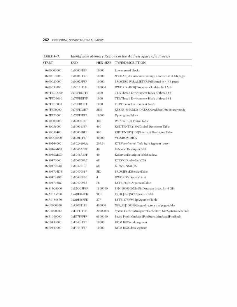
262 EXPLORING WINDOWS 2000 MEMORY
TABLE 4-9. Identifiable Memory Regions in the Address Space of a Process
START END HEX SIZE TYPE/DESCRIPTION
0x00000000 0x0000FFFF 10000 Lower guard block
0x00010000 0x0001FFFF 10000 WCHAR[]/Environment strings, allocated in 4-KB pages
0x00020000 0x0002FFFF 10000 PROCESS_PARAMETERS/allocated in 4-KB pages
0x00030000 0x0012FFFF 100000 DWORD [4000]/Process stack (default: 1 MB)
0x7FFDD000 0x7FFDDFFF 1000 TEB/Thread Environment Block of thread #2
0x7FFDE000 0x7FFDEFFF 1000 TEB/Thread Environment Block of thread #1
0x7FFDF000 0x7FFDFFFF 1000 PEB/Process Environment Block
0x7FFE0000 0x7FFE02D7 2D8 KUSER_SHARED_DATA/SharedUserData in user-mode
0x7FFF0000 0x7FFFFFFF 10000 Upper guard block
0x80000000 0x800003FF 400 IVT/Interrupt Vector Table
0x80036000 0x800363FF 400 KGDTENTRY[80]/Global Descriptor Table
0x80036400 0x80036BFF 800 KIDTENTRY[100]/Interrupt Descriptor Table
0x800C0000 0x800FFFFF 40000 VGA/ROM BIOS
0x80244000 0x802460AA 20AB KTSS/user/kernel Task State Segment (busy)
0x8046AB80 0x8046ABBF 40 KeServiceDescriptorTable
0x8046ABC0 0x8046ABFF 40 KeServiceDescriptorTableShadow
0x80470040 0x804700A7 68 KTSS/KiDoubleFaultTSS
0x804700A8 0x8047010F 68 KTSS/KiNMITSS
0x804704D8 0x804708B7 3E0 PROC[F8]/KiServiceTable
0x804708B8 0x804708BB 4 DWORD/KiServiceLimit
0x804708BC 0x804709B3 F8 BYTE[F8]/KiArgumentTable
0x814C6000 0x82CC5FFF 1800000 PFN[100000]/MmPfnDatabase (max. for 4 GB)
0xA01859F0 0xA01863EB 9FC PROC[27F]/W32pServiceTable
0xA0186670 0xA01868EE 27F BYTE[27F]/W32pArgumentTable
0xC0000000 0xC03FFFFF 400000 X86_PE[100000]/page-directory and page-tables
0xC1000000 0xE0FFFFFF 20000000 System Cache (MmSystemCacheStart, MmSystemCacheEnd)
0xE1000000 0xE77FFFFF 6800000 Paged Pool (MmPagedPoolStart, MmPagedPoolEnd)
0xF0430000 0xF043FFFF 10000 ROM BIOS code segment
0xF0440000 0xF044FFFF 10000 ROM BIOS data segment
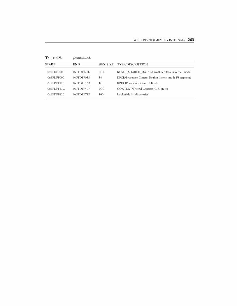
WINDOWS 2000 MEMORY INTERNALS 263
TABLE 4-9. (continued)
START END HEX SIZE TYPE/DESCRIPTION
0xFFDF0000 0xFFDF02D7 2D8 KUSER_SHARED_DATA/SharedUserData in kernel-mode
0xFFDFF000 0xFFDFF053 54 KPCR/Processor Control Region (kernel-mode FS segment)
0xFFDFF120 0xFFDFF13B 1C KPRCB/Processor Control Block
0xFFDFF13C 0xFFDFF407 2CC CONTEXT/Thread Context (CPU state)
0xFFDFF620 0xFFDFF71F 100 Lookaside list directories