Embed Size (px)
DESCRIPTION
Researchon local wave speed in a draft tube with cavitation
Citation preview

Seediscussions,stats,andauthorprofilesforthispublicationat:http://www.researchgate.net/publication/271204433
Experimentalinvestigationofthelocalwavespeedinadrafttubewithcavitationvortexrope
CONFERENCEPAPERinIOPCONFERENCESERIESEARTHANDENVIRONMENTALSCIENCE·SEPTEMBER2014
DOI:10.1088/1755-1315/22/3/032037
READS
43
6AUTHORS,INCLUDING:
ArthurFavrel
ÉcolePolytechniqueFédéraledeLausanne
6PUBLICATIONS4CITATIONS
SEEPROFILE
AndresMüller
ÉcolePolytechniqueFédéraledeLausanne
16PUBLICATIONS22CITATIONS
SEEPROFILE
ChristopheNicolet
ÉcolePolytechniqueFédéraledeLausanne
57PUBLICATIONS298CITATIONS
SEEPROFILE
FrançoisAvellan
ÉcolePolytechniqueFédéraledeLausanne
263PUBLICATIONS1,419CITATIONS
SEEPROFILE
Availablefrom:ChristianLandry
Retrievedon:10October2015

This content has been downloaded from IOPscience. Please scroll down to see the full text.
Download details:
IP Address: 128.178.4.136
This content was downloaded on 22/01/2015 at 16:45
Please note that terms and conditions apply.
Experimental investigation of the local wave speed in a draft tube with cavitation vortex rope
View the table of contents for this issue, or go to the journal homepage for more
2014 IOP Conf. Ser.: Earth Environ. Sci. 22 032037
(http://iopscience.iop.org/1755-1315/22/3/032037)
Home Search Collections Journals About Contact us My IOPscience

Experimental investigation of the local wave speed in a draft tube with cavitation vortex rope
C Landry 1, A Favrel1, A Müller 1, C Nicolet2, K Yamamoto1, F Avellan1
1 EPFL Laboratory for Hydraulic Machines, Avenue de Cour 33bis, 1007 Lausanne, Switzerland
2 Power Vision engineering sàrl, Ch. des Champs-Courbes 1, 1024 Ecublens, Switzerland
E-mail: [email protected]
Abstract. Hydraulic machines operating in a wider range are subjected to cavitation developments inducing undesirable pressure pulsations which could lead to potential instability of the power plant. The occurrence of pulsating cavitation volumes in the runner and the draft tube is considered as a mass source of the system and is depending on the cavitation compliance. This dynamic parameter represents the cavitation volume variation with the respect to a variation of pressure and defines implicitly the local wave speed in the draft tube. This parameter is also decisive for an accurate prediction of system eigen frequencies. Therefore, the local wave speed in the draft tube is intrinsically linked to the eigen frequencies of the hydraulic system. Thus, if the natural frequency of a hydraulic system can be determined experimentally, it also becomes possible to estimate a local wave speed in the draft tube with a numerical model.
In the present study, the reduced scale model of a Francis turbine (�=0.29) was investigated at off-design conditions. In order to measure the first eigenmode of the hydraulic test rig, an additional discharge was injected at the inlet of the hydraulic turbine at a variable frequency and amplitude to excite the system. Thus, with different pressure sensors installed on the test rig, the first eigenmode was determined. Then, a hydro-acoustic test rig model was developed with the In-house EPFL SIMSEN software and the local wave speed in the draft tube was adjusted to obtain the same first eigen frequency as that measured experimentally. Finally, this method was applied for different Thoma and Froude numbers at part load conditions.
1. Introduction Nowadays, the pump-storage power plants are a proven solution for storing electricity at large scale and offering flexibility to the power management. Therefore, the hydraulic machines are increasingly subject to off-design operation, start-up and shutdown sequences. At off-design operating points, a swirling flow at the outlet runner remains and gives rise to a cavitation vortex rope. This cavitation vortex rope is described as an excitation source for the hydraulic system with a frequency of about 0.2 to 0.4 times the rotational frequency [1]. Interaction between this excitation source and system eigen frequency may result in resonance effect and induce a draft tube surge and electrical power swings [2][3]. Then it becomes necessary to predict the eigen frequency of a power plant as a function of its
27th IAHR Symposium on Hydraulic Machinery and Systems (IAHR 2014) IOP PublishingIOP Conf. Series: Earth and Environmental Science 22 (2013) 032037 doi:10.1088/1755-1315/22/3/032037
Content from this work may be used under the terms of the Creative Commons Attribution 3.0 licence. Any further distributionof this work must maintain attribution to the author(s) and the title of the work, journal citation and DOI.
Published under licence by IOP Publishing Ltd 1

hydroacoustic parameters. Moreover, the volume of the cavitation vortex rope is dependent on the cavitation number σ and affects the parameters characterizing the hydroacoustic behavior and the eigen frequencies of the entire power plant. Indeed, the presence of cavitation drastically slows the propagation wave in the draft tube. Therefore, there is an intrinsic link between the wave speed in the draft tube and all eigen frequencies.
Many numerical models were developed for hydraulic systems with a bubbly air-water mixture and
a review about one-dimensional bubbly flow is given by van Wijngaarden [4]. The simpliest model descibed by Wood [5] assumes a homogeneous mixture containing small, isothermal, non diffusing gas bubbles of uniform radius and devoid of surface tension effects. Several investigations about a single oscillating bubble in a liquid have shown that the influence of both the fluid and the gas compressibility and the surface tension can be strong [6]. Thus, Rath developed a theoretical definition linking the wave speed with the void fraction, taking into account these influences for a homogeneous air-water bubbly mixture flow.
However, experimental and theoritical wave speeds published by Henry et al. [7] showed
significant differences between bubbly flow, slug flow and stratified flow. Thus, the theoritical developed models for homogeneous flow cannot be used for the cavitation vortex rope. Therefore, an alternative method based on experimental data and a numerical model is presented in this paper to identify the local wave speed as a function of the Thoma number for a cavitation vortex rope. First, the eigen frequency of a hydraulic test rig including a reduced scale model of a Francis turbine was experimentally characterized with a modal analysis by using an external excitation source. Then, a numerical model of the hydraulic system was developped with particular attention to the modeling of the cavitation vortex rope. As the local wave speed in the draft tube is intrinsically linked to the eigen frequencies of the system, it becomes possible to estimate this local wave speed for a given Thoma number.
2. Experimental setup The reduced scale of a Francis turbine was tested in the EPFL PF3 test rig shown in figure 1. Two 400 kW centrifugal pumps connected in series features a maximum head of 100 m and a maximum discharge of 1.4 m3/s. The characterization of the test rig eigenmodes was determined in a modal analysis with an external excitation source. This source was designed and constructed to inject or extract a periodical discharge at a given frequency in the upstream pipe and is sketched in figure 2.
Figure 1. Scheme of the EPFL PF3 test rig with the excitation system
Francis Turbine
Injection Location
Pump
27th IAHR Symposium on Hydraulic Machinery and Systems (IAHR 2014) IOP PublishingIOP Conf. Series: Earth and Environmental Science 22 (2013) 032037 doi:10.1088/1755-1315/22/3/032037
2

The excitation system uses a variable speed pump KSB Movichrom G 15/5 which permits to
control the amplitude of excitation. The modulation of the discharge is achieved through a rotating valve. This valve is driven by a variable speed motor permitting to excite the test rig in a range of frequency from 1 Hz to 15 Hz. Moreover, an air vessel dynamically decouples the injection pump from the entire hydraulic circuit. Finally, the average discharge of excitation is measured by a magnetic flow meter ADMAG-AE 205. These measurements were synchronized with the pressure measurements, the flow meter of the excitation system and the test rig parameters measurement, such as cavitation number, head, discharge and torque. Moreover, with 27 sensors placed throughout the hydraulic circuit, the eigen shape can accurately be surveyed. 12 pressure sensors are located along the test rig penstock. Moreover, 8 pressure sensors are placed in the cone on two different sections at 90° to one another and 4 pressure sensors are installed in the elbow and the diffuser. Finally, one pressure sensors are placed between the guide vanes and 2 other are installed on the excitation system penstock to measure the fluctuating discharge. It is interesting to note that the location of the sensors was deliberately concentrated in the draft tube and on the first part of the test rig to reduce the error on the eigen shape.
Figure 2. Sketch of the excitation system
The modal analysis was performed at part load, in both cavitation-free and cavitation condition, for two different operating points, described in Table 1. For each sigma value, different excitation frequencies were generated to determine the eigenmode of the hydraulic test rig for a given operating point.
Table 1. Selected turbine operating points
nED QED Fr σ PL 1 Part Load 1 0.8 [6.56, 7.66, 8.75, 9.85] [0.08 - 0.15] PL 2 Part Load 1 0.64 [7.66, 8.75, 9.85] [0.11 - 0.20]
For each operating point, pressure fluctuations measurements were synchronized with the torque
fluctuations measurements and acquired simultaneously with a PXI system using a sampling frequency of 1000 Hz. A high-speed video camera was also used to visualize the dynamic behavior of the cavitation volume vortex rope in the cone.
3. Numerical model A hydroacoustic test rig model was developed with the EPFL SIMSEN software. The modeling of the hydraulic components is based on equivalent electrical scheme representation. The momentum and the
27th IAHR Symposium on Hydraulic Machinery and Systems (IAHR 2014) IOP PublishingIOP Conf. Series: Earth and Environmental Science 22 (2013) 032037 doi:10.1088/1755-1315/22/3/032037
3
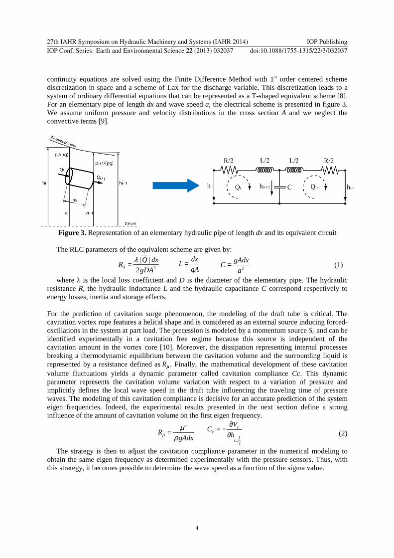
continuity equations are solved using the Finite Difference Method with 1st order centered scheme discretization in space and a scheme of Lax for the discharge variable. This discretization leads to a system of ordinary differential equations that can be represented as a T-shaped equivalent scheme [8]. For an elementary pipe of length dx and wave speed a, the electrical scheme is presented in figure 3. We assume uniform pressure and velocity distributions in the cross section A and we neglect the convective terms [9].
Figure 3. Representation of an elementary hydraulic pipe of length dx and its equivalent circuit
The RLC parameters of the equivalent scheme are given by:
2
| |
2
Q dxR
gDAλλ=
dxL
gA=
2
gAdxC
a=
(1)
where λ is the local loss coefficient and D is the diameter of the elementary pipe. The hydraulic resistance R, the hydraulic inductance L and the hydraulic capacitance C correspond respectively to energy losses, inertia and storage effects.
For the prediction of cavitation surge phenomenon, the modeling of the draft tube is critical. The cavitation vortex rope features a helical shape and is considered as an external source inducing forced-oscillations in the system at part load. The precession is modeled by a momentum source Sh and can be identified experimentally in a cavitation free regime because this source is independent of the cavitation amount in the vortex core [10]. Moreover, the dissipation representing internal processes breaking a thermodynamic equilibrium between the cavitation volume and the surrounding liquid is represented by a resistance defined as��. Finally, the mathematical development of these cavitation volume fluctuations yields a dynamic parameter called cavitation compliance Cc. This dynamic parameter represents the cavitation volume variation with respect to a variation of pressure and implicitly defines the local wave speed in the draft tube influencing the traveling time of pressure waves. The modeling of this cavitation compliance is decisive for an accurate prediction of the system eigen frequencies. Indeed, the experimental results presented in the next section define a strong influence of the amount of cavitation volume on the first eigen frequency.
''
RgAdxµµ
ρ=
1
2
cc
i
VC
h+
∂= −∂
(2)
The strategy is then to adjust the cavitation compliance parameter in the numerical modeling to obtain the same eigen frequency as determined experimentally with the pressure sensors. Thus, with this strategy, it becomes possible to determine the wave speed as a function of the sigma value.
27th IAHR Symposium on Hydraulic Machinery and Systems (IAHR 2014) IOP PublishingIOP Conf. Series: Earth and Environmental Science 22 (2013) 032037 doi:10.1088/1755-1315/22/3/032037
4

Figure 4. Representation of the draft tube with a cavitation vortex rope and its equivalent circuit
To compute the eigen frequency for each operating point, an eigenvalue study of the non-linear hydraulic system was conducted. The electrical analogy of the hydraulic model describes the dynamic behavior as a first order differential equation system in the following matrix form:
[ ] ( ) ( )dxA B x x V x
dt+ ⋅ =
rrr r r
(3)
where ��� and ����� are the state global matrices of dimension � � �, � and ����� are respectively the state vector and the boundary conditions vector with n components. The eigenvalues are based on the linearization of the set of equations around the operating point [11]. Damping and oscillation frequency of the eigenmodes are respectively given by the real part and the imaginary part of the eigenvalues.
4. Results and discussions For a given QED, Froude and Thoma number, the hydraulic system was experimentally excited in a frequency range to determine the eigenmode of the test rig. For each excitation frequency, the hydraulic system response was measured with 27 pressure sensors located on the test rig. For instance, the figure 5a shows the cross spectral density function of the two pressure sensors, named P6 and ES1, divided by the one-sided autospectral density function of reference sensor, located at the turbine inlet, for 21 excitation frequencies for the PL1 operating point with a Froude number equal to 8.75 and a Thoma number equal to 0.15. The amplitude obtained for each given excitation frequency is plotted in the figure 5b. The two pics highlighted by the red arrows indicate the first and the second eigen frequencies of the hydraulic system.
a) Spectrum obtained for each excitation frequency b) Amplitude obtained for each excitation frequency
Figure 5. Cross spectral density function of the P6 and ES1 pressure sensors, divided by the one-sided autospectral density function of the P1 reference sensor located at the turbine inlet.
1st eigen frequency
2nd eigen frequency
27th IAHR Symposium on Hydraulic Machinery and Systems (IAHR 2014) IOP PublishingIOP Conf. Series: Earth and Environmental Science 22 (2013) 032037 doi:10.1088/1755-1315/22/3/032037
5

The figure 6 described the hydraulic EPFL PF3 test rig response for the first and the second eigen frequencies. Each value represents the cross spectral density function divided by the one-sided autospectral density function of P1 reference sensor located at the turbine inlet.
Figure 6. The hydraulic EPFL PF3 test rig response for the first and the second eigen frequencies
Applying the same methodology for all operating points, figure 7a shows the relation between the Thoma number and the first eigen frequency of the hydraulic system. In general, increasing the volume of the vortex rope decreases the eigen frequency of the system. In addition, the Froude number affects the distribution of cavitation in the flow as it determines the pressure gradient relatively to the size of the machine. The Froude number influence remains small and its decrease causes a slight reduction of the eigen frequency. Finally, the difference between the two operating points is related to the pressure level in the draft tube.
a) Natural frequency as a function of the Thoma
number for operating points PL1 and PL2 b) Wave speed as a function of the Thoma number
for operating points PL1 and PL2
Figure 7. Evolution of the natural frequency and the wave speed as a function of the Thoma number
By knowing the first eigen frequency for each operating point, it is possible to determine the wave speed in the draft tube by using the one-dimensional numerical model of the hydraulic system. In fact, the wave speed in the cone is determined to obtain the same natural frequency as that measured experimentally. The relation between the Thoma number and the wave speed is defined in the figure 7b. Thus, it can be observed that the wave speeds drop between 10 and 60 m/s when the cavitation vortex rope is present. Such low wave speeds imply that the convective part of the Navier-Stokes equation cannot be simplified anymore when the cavitation vortex rope occurs. A new numerical
f1 = 5.615 Hz f2 = 8.545 Hz
P6 P6
Francis Turbine
Injection Location
Pump
27th IAHR Symposium on Hydraulic Machinery and Systems (IAHR 2014) IOP PublishingIOP Conf. Series: Earth and Environmental Science 22 (2013) 032037 doi:10.1088/1755-1315/22/3/032037
6

model taking into account this physical term has been developed [12] and also includes the divergent geometry of the draft tube. Finally, as was pointed out to the natural frequency, there is always a strong dependence of the wave speed with the pressure in the draft tube, but also with the Thoma number linked to the implementation of the turbine. It will then be necessary to create dimensionless parameters to compare the two different operating points.
5. Conclusion Many numerical models have been developed for bubbly air-water mixture. However, significant differences between bubbly flow, slug flow and stratified flow indicate that the theoretical formulations are inappropriate for a cavitation vortex rope. Therefore, an alternative method based on experimental data and numerical model was developed to identify the local wave speed as a function of Thoma number. As the local wave speed in the draft tube is intrinsically linked to the natural frequency, it becomes possible to estimate the resonance effect and avoid the draft tube surge and electrical swings.
The results indicate that the wave speeds drop between 10 and 60 m/s when the cavitation vortex rope is present. Such low wave speeds imply that the convective part of the Navier-Stokes equation cannot be simplified anymore when the cavitation vortex rope occurs. A new numerical model taking into account this physical term will be used. Moreover, there is always a strong dependence of the wave speed with the pressure in the draft tube, but also with the Thoma number linked to the implementation of the turbine. It will then be necessary to create dimensionless parameters to compare the two different operating points and thus define a general relation describing the local wave speed in a draft tube with a cavitation vortex rope.
Acknowledgments The research leading to the results published in this paper is part of the HYPERBOLE research project, granted by the European Commission (ERC/FP7-ENERGY-2013-1-Grant 608532). The authors would like to thank the Energy Program of The Ark, the Foundation for Innovation of Valais Canton, for their financial support and BC Hydro for making available the reduced scale model, in particular Danny Burggraeve and Jacob Losfin. Moreover, the authors would like to acknowledge the commitment of the Laboratory for Hydraulic Machines’ technical staff, especially Georges Crittin, Maxime Raton, Alain Renaud and Vincent Berruex.
Nomenclature A a C CC D Fr g h
Cross-section area [m2] Wave speed [m/s] Hydraulic capacitance [m2] Cavitation Compliance [m2] Diameter [m] Froude number [-] Gravity [m/s2] Piezometric head [m]
L nED
Q QED Rλ Rµ
s VC
Hydraulic inductance [s2/m2] IEC speed factor [-] Discharge [m3/s] IEC discharge factor [-] Hydraulic resistance [s/m2] Viscoelastic resistance [s/m2] Complex eigenvalue [-] Cavitation volume [m3]
λ µ’’ ρ σ σk
χ ωk
Local loss coefficient [-] Bulk viscosity [Pa s] Density [kg/m3] Thoma number [-] Damping [1/s] Mass flow gain factor [s] Oscillation pulsation [rad/s]
References [1] Nishi, M., 1984, Surging characteristics of conical and elbow type draft tubes. 12th IAHR
Symposium on hydraulic Machinery and Systems, Stirling, pp. 272-283. [2] Fritsch, A. and Maria, D., 1988, Comportement dynamique d’une turbine Francis à charge
partielle : comparaison modèle-prototype. La Houille Blanche, pp. 273-280.
27th IAHR Symposium on Hydraulic Machinery and Systems (IAHR 2014) IOP PublishingIOP Conf. Series: Earth and Environmental Science 22 (2013) 032037 doi:10.1088/1755-1315/22/3/032037
7

[3] Favrel A, Landry C, Müller A and Avellan F, 2012, Experimental identification and study of hydraulic resonance test rig with Francis turbine operating at partial load, 26th IAHR Symposium on Hydraulic Machinery and Systems, Beijing, China
[4] Wijngaarden, L. v., 1972. Heat Mass Transfer 6, Enschede, The Netherlands: Twente Institute of Technology, Vol. 637.
[5] Wood, A. B., 1941, A Textbook of Sound, London, G. Bell and Sons Ltd. [6] Rath H.J., 1981, Unsteady Pressure Waves and Shock Waves in elastic Tubes Containing
Bubbly Air-Water Mitures, Acta Mechanica 38, pp 1-17. [7] Henry, R. E., Grolmes, M. A., Fauske, H. K., 1969, Propagation velocity of pressure waves in
gas-liquid mixtures. Concurrent Gas-Liquid Flow, pp. 1-18. [8] Nicolet, C., Alligné, S., Kawkabani, B., Koutnik, J., Simond, J.J. and Avellan, F., 2009,
Stability Study of Francis Pump-turbine at Runaway, 3rd IAHR International Meeting of the Workgroup on Cavitation and Dynamic Problems in Hydraulic Machinery and Systems.
[9] Wylie, E .B. and Streeter, V.L., 1993, Fluid transients in systems, Prentice Hall, Englewood Cliffs, N.J.
[10] Dörfler, P. K., 1982, System dynamics of the Francis turbine half load surge, 11th IAHR Symposium on the Hydraulic Machinery and systems, Amsterdam, Netherlands, Paper N° 39
[11] Alligné, S., Nicolet, C., Allenbach, P., Kawkabani, B., Simon, J.J., Avellan, F., 2009, Influence of the Francis turbine location under vortex rope excitation on the hydraulic system stability, International Journal of Fluid Machinery and Systems, Vol. 2.
[12] Alligné, S., Nicolet, C., Tsujimoto, Y., Avellan, A., 2014, Cavitation surge modelling in Francis turbine draft tube, Journal of Hydraulic Research.
27th IAHR Symposium on Hydraulic Machinery and Systems (IAHR 2014) IOP PublishingIOP Conf. Series: Earth and Environmental Science 22 (2013) 032037 doi:10.1088/1755-1315/22/3/032037
8