Embed Size (px)
Citation preview
www.elsevier.com/locate/enconman
Energy Conversion and Management 46 (2005) 1523–1542
Experimental evaluation of energy and exergy efficiency of aseasonal latent heat storage system for greenhouse heating
H. Huseyin Ozturk *
Department of Agricultural Machinery, Faculty of Agriculture, University of Cukurova, Balcali, 01330 Adana, Turkey
Received 7 January 2004; received in revised form 25 March 2004; accepted 18 July 2004
Available online 15 September 2004
Abstract
In the following work, a seasonal thermal energy storage using paraffin wax as a PCM with the latent
heat storage technique was attempted to heat the greenhouse of 180 m2 floor area. The system consists
mainly of five units: (1) flat plate solar air collectors (as heat collection unit), (2) latent heat storage(LHS) unit, (3) experimental greenhouse, (4) heat transfer unit and (5) data acquisition unit. The external
heat collection unit consisted of 27 m2 of south facing solar air heaters mounted at a 55� tilt angle. The
diameter and the total volume of the steel tank used as the latent heat storage unit were 1.7 m and 11.6
m3, respectively. The LHS unit was filled with 6000 kg of paraffin, equivalent to 33.33 kg of PCM per
square meter of the greenhouse ground surface area. Energy and exergy analyses were applied in order
to evaluate the system efficiency. The rate of heat transferred in the LHS unit ranged from 1.22 to 2.63
kW, whereas the rate of heat stored in the LHS unit was in the range of 0.65–2.1 kW. The average daily
rate of thermal exergy transferred and stored in the LHS unit were 111.2 W and 79.9 W, respectively. Dur-ing the experimental period, it was found that the average net energy and exergy efficiencies were 40.4% and
4.2%, respectively. The effect of the temperature difference of the heat transfer fluid at the inlet and outlet of
the LHS unit on the computed values of the energy and exergy efficiency is evaluated during the charging
period.
� 2004 Elsevier Ltd. All rights reserved.
Keywords: Latent heat storage; Paraffin; Energy and exergy efficiency
0196-8904/$ - see front matter � 2004 Elsevier Ltd. All rights reserved.
doi:10.1016/j.enconman.2004.07.001
* Tel.: +90 322 3386408; fax: +90 322 3387165.
E-mail address: [email protected]
Nomenclature
A area, m2
cp specific heat, J/kg Kd diameter, mk heat transfer coefficient, W/m2KL length, m_Q rate of heat transfer, Wt time, sT temperature, Ks thickness, m_v volumetric flow rate, m3/s_W power consumption, W
Greek letters_N rate of exergy transfer, WW exergy efficiency, %a heat convection coefficient, W/m2Kg energy efficiency, %k heat conduction coefficient, W/mKq density, kg/m3
Subscripts
a ambientb bottomc charginge equivalenth horizontali inlet, or innerl losso outlet, or outerp paraffinr references storedt transferred1 steel plate2 glass wool3 storage tank
1524 H.H. Ozturk / Energy Conversion and Management 46 (2005) 1523–1542
H.H. Ozturk / Energy Conversion and Management 46 (2005) 1523–1542 1525
1. Introduction
Solar energy, an abundant, clean and safe source, is an attractive substitute for conventionalfuels for passive and active heating applications. During the day, excess solar heat is collectedfor short or long term storage, and it is recovered at night in order to satisfy the heating needsof greenhouses. Efficient and economical heat storage is the main factor in utilization of solar en-ergy for agricultural purposes. Solar thermal energy can be stored as sensible heat, latent heat,heat of reaction or a combination of these. In most storage systems, it is stored as sensible heatin materials such as water and rocks. In air collection systems, rock beds are normally used tostore heat, while water tanks store the heat in liquid systems. In latent heat storage (LHS) systems,the latent heat arising from the phase change of a material is used for thermal energy storage. Thephase change materials (PCMs) can store large amounts of heat (latent heat of fusion) in changingphase from solid to liquid. LHS systems using PCM, in general, provide much higher energy stor-age density than systems using sensible heat storage. For solar heating applications, the use ofLHS systems for thermal energy storage has become an attractive design option in terms ofconstruction cost and storage efficiency. The efficiency of seasonal storage as well as that of dailystorage depends on system configurations, climate conditions and various set points for environ-mental control.
Several authors have investigated the present status, technical potentials and regional distribu-tion of renewable energy resources in Turkey [1–18] and concluded that Turkey has extensiverenewable energy resources that can be developed as a significant source of energy. Turkey alsohas great solar energy potential due to its location in the Mediterranean Region (36� and 42�North latitudes). The sunshine period of Turkey is 2624 h/year with a maximum of 365 h/monthin July and a minimum of 103 h/month in December. The main solar radiation intensity is about3.67 kWh/m2 day. The cumulative total of this is about 1.340 MWh/m2 year. The amount of solarradiation received over all of Turkey, in other words, the gross solar energy potential is 3517 EJ/year [19]. With rising energy costs and an increasing demand for renewable energy sources, ther-mal energy storage (TES) systems are becoming an interesting option. TES is a key component ofany successful thermal system, and a good TES system should allow minimum thermal energylosses [20]. In recent years, TES has been recognized as a potentially significant means by whichprimary energy consumption can be reduced in domestic, commercial and industrial processes[21]. Comprehensive studies have been conducted concerning the application and modelling ofLHS systems and the thermal properties of PCMs by many researchers [6,22–49]. Latent heatthermal energy storage has been proved to be an effective method for utilization of clean energysources, such as solar energy, because of its high energy storage density and small temperaturevariation from storage to extraction. Therefore, a number of investigations that aimed at improv-ing the efficiency of LHS systems have been done by some researchers in the design, modeling andtesting of LHS systems [50–57]. El-Dessouky and Al-Juwayhel [58] developed second law analysisfor a phase change thermal energy storage system using paraffin wax and calcium chloride hexa-hydrate as the PCM.
Consequently, this study is devoted to an analysis and operation of a large scale LHS system forgreenhouse heating. Energy and exergy analyses were applied for evaluating the efficiency of a so-lar thermal latent heat storage application. In this experimental study, solar energy was storedusing paraffin as a PCM with the latent heat technique for heating a plastic greenhouse of
1526 H.H. Ozturk / Energy Conversion and Management 46 (2005) 1523–1542
180 m2. In the present paper, the energy and exergy efficiencies of a LHS system, using paraffin asthe PCM, defined as the ratio of the energy and exergy stored in the LHS unit to the energy andexergy originally delivered to the LHS unit, respectively, are introduced for the first time. Thus,the performance of the LHS system for greenhouse heating was evaluated by energy and exergyanalyses, and the energy and exergy efficiencies of the LHS system were compared during thecharging periods. The objectives of the present study are: (1) to achieve more efficient utilizationof solar energy in greenhouse heating systems; (2) to determine the annual fraction of the green-house heating demand that can be supplied by the LHS system under ambient conditions of theCukurova region in Turkey; (3) to investigate the thermal performance of the LHS system usingparaffin as a PCM under the operating conditions; (4) to design and build external collection andheat storage units based on paraffin with a melting temperature range of 48–60 �C and latent heatof melting of 190 kJ/kg; (5) to compare the energy efficiency of the LHS system with its exergyefficiency; and (6) to determine the feasibility of using a PCM as a possible alternative to otherstorage techniques for storage of solar thermal energy for the Cukurova climate.
2. Description of the system
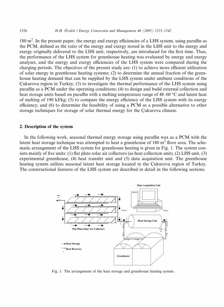
In the following work, seasonal thermal energy storage using paraffin wax as a PCM with thelatent heat storage technique was attempted to heat a greenhouse of 180 m2 floor area. The sche-matic arrangement of the LHS system for greenhouse heating is given in Fig. 1. The system con-sists mainly of five units: (1) flat plate solar air collectors (as heat collection unit), (2) LHS unit, (3)experimental greenhouse, (4) heat transfer unit and (5) data acquisition unit. The greenhouseheating system utilizes seasonal latent heat storage located in the Cukurova region of Turkey.The constructional features of the LHS system are described in detail in the following sections.
V E R TOP LAM A V E
KONTROL N TE S
4
5
1 2
3
FANA
FAN
B
IS I D EP O LAM A N TE S
IS I TOP LAM A N TE S
PLAS T K S E RA
IS I DE P OLAM A HATTI
Heat Storage Unit
Valves Valves
Flat Plate Solar Air Collectors
Greenhouse
Heat Storage
Heat Recovery
Data Acquisition Unit
Fig. 1. The arrangement of the heat storage and greenhouse heating system.
H.H. Ozturk / Energy Conversion and Management 46 (2005) 1523–1542 1527
2.1. Flat plate solar air collectors
Flat plate solar air collectors were used to collect solar energy. The external heat collection unitconsisted of 27 m2 of south facing solar air heaters mounted at a 55� tilt angle (Fig. 1). Solar aircollectors that have packed air flow passages were used in the heat collection unit. Each of thesolar air collectors has an absorber plate area of 1.5 m2. The Raschig ring type of packing wasused to increase the heat transfer from the plates to the heat transfer fluid underneath the absor-ber plates of the air collectors. The characteristic diameter of the Raschig rings, made of polyvinylchloride (PVC) tube, was 0.05 m. The aluminum based absorber of the air heaters is covered witha 4 mm glass sheet, and the underside is insulated with glass wool. The dimensions of the air col-lectors are 1.9 · 0.9 m, and 18 of them form the external heat collection system. The absorber sur-face area of the installed air collectors was 0.225 m2 per square meter of the tunnel greenhouseground surface area. The heat collection unit was supplied with air from the environment by acentrifugal fan that had a volumetric flow rate of 600 m3/h. The heat collection unit was installedoutside the greenhouse and mounted on a galvanized steel structure.
2.2. Latent heat storage unit
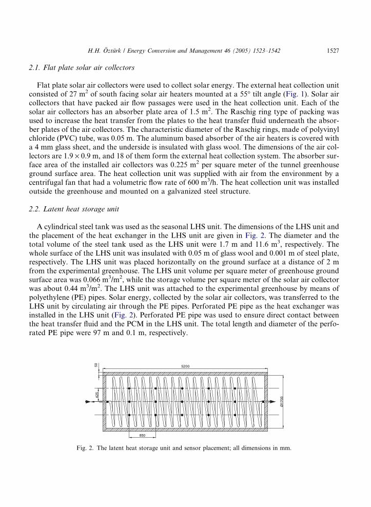
A cylindrical steel tank was used as the seasonal LHS unit. The dimensions of the LHS unit andthe placement of the heat exchanger in the LHS unit are given in Fig. 2. The diameter and thetotal volume of the steel tank used as the LHS unit were 1.7 m and 11.6 m3, respectively. Thewhole surface of the LHS unit was insulated with 0.05 m of glass wool and 0.001 m of steel plate,respectively. The LHS unit was placed horizontally on the ground surface at a distance of 2 mfrom the experimental greenhouse. The LHS unit volume per square meter of greenhouse groundsurface area was 0.066 m3/m2, while the storage volume per square meter of the solar air collectorwas about 0.44 m3/m2. The LHS unit was attached to the experimental greenhouse by means ofpolyethylene (PE) pipes. Solar energy, collected by the solar air collectors, was transferred to theLHS unit by circulating air through the PE pipes. Perforated PE pipe as the heat exchanger wasinstalled in the LHS unit (Fig. 2). Perforated PE pipe was used to ensure direct contact betweenthe heat transfer fluid and the PCM in the LHS unit. The total length and diameter of the perfo-rated PE pipe were 97 m and 0.1 m, respectively.
850
Ø1700
5200
425
50
Fig. 2. The latent heat storage unit and sensor placement; all dimensions in mm.
1528 H.H. Ozturk / Energy Conversion and Management 46 (2005) 1523–1542
2.3. Heat storage material
In general, materials that have a large change in internal energy per unit volume minimize thespace needed to store energy. A large number of organic and inorganic substances are known tomelt with a high heat of fusion in any required temperature range (0–120 �C). However, for theiremployment as heat storage materials in LHS systems, these PCMs must exhibit certain desirablethermodynamic, kinetic and chemical properties. Moreover, economic considerations of cost andlarge scale availability of the materials must be considered. Paraffin was used as a PCM in thepresent LHS system due to several desirable properties. Paraffins qualify as heat of fusion storagematerials due to their availability in a large temperature range and their reasonably high heat offusion. Furthermore, they are known to freeze without subcooling. Because of cost considera-tions, however, only technical grade paraffins may be used as PCMs in LHS systems. Hawladeret al. [59] found that encapsulated paraffin wax shows a good potential as a storage materials.
In the selection of PCM for the present LHS system, the following desirable properties of theparaffin as a PCM were taken into account: high latent heat of fusion per unit mass, chemical sta-bility, melting in the desired operating temperature range, small volume changes during the phasetransition, self nucleating and fast phase transition, little subcooling during freezing, availabilityin large quantities, non-corrosiveness to construction materials, easily packaged and inexpensive.The distribution of C–atoms of the technical grade paraffin used in this experiment is C22–C45,and its purity (oil content) is 5%. The thermal properties of the paraffin used as the PCM weremeasured with a differential scanning calorimeter (DSC): the melting temperature range andthe latent heat of fusion were 48–60 �C and 190 kJ/kg, respectively. The PCM required for thegreenhouse heating was calculated on the basis of the heat storage capacity per unit volume ofthe selected paraffin and the total heat requirement of the experimental greenhouse. The LHS unitwas filled with 6000 kg of paraffin, equivalent to 33.33 kg of PCM per square meter of the green-house ground surface area.
2.4. Experimental greenhouse
The experiments were conducted in a PE greenhouse that was aligned north–south. The exper-imental greenhouse, consisting of galvanized steel tube, has continuous side openings operated bya rolling mechanism. The openings in the sidewalls, created by rolling a plastic film up or down,were used for ventilation. The greenhouse was covered with a double skin PE material (thicknessof 0.35 mm) that contains ultraviolet (UV) and infrared (IR) stabilizers. The dimensions of thegreenhouse were: width 12 m; length 15 m and height 3 m. The warm air from the LHS unitwas distributed by perforated PE ducts lying on the ground surface inside the greenhouse. Thediameter of the PE ducts was 0.15 m.
2.5. Heat transfer unit
In this experiment, heat transfer with forced convection between the heat collection unit, LHSunit and the experimental greenhouse was accomplished with two centrifugal fans (fan A and fanB in Fig. 1). Two differential thermostats were used to control the charging and discharging proc-ess by controlling the centrifugal fans, which can be operated independently. When the difference
H.H. Ozturk / Energy Conversion and Management 46 (2005) 1523–1542 1529
between the outside air temperature and the LHS system temperature exceeds the preset value,one of the differential thermostats activates fan A (charging fan). During the summer, heat col-lected by the flat plate solar air collectors was used to charge the LHS unit. During the chargingoperation, the air from outside was circulated through the heat collection unit by the charging fanand then passed through the LHS unit. During the winter, when the air temperature of the exper-imental greenhouse fell below a preset value, fan B (discharging fan) was activated during theextraction operation. The discharging fan drove the greenhouse air through the LHS unit duringthe night and then returned it to the interior of the experimental greenhouse via the perforated PEducts. The operation of the electric motor activating the discharging fan was controlled by a timeclock between 22:00 and 02:00 h.
2.6. Operational procedures
There are many factors that affect the performance of a LHS system, such as the average tem-peratures of the LHS unit and the fractions of time during which the LHS unit is charged anddischarged. These factors depend primarily on the amount of incident solar energy relative to theheating load of the experimental greenhouse. In this experiment, the directions of the heat flowbetween the heat collection unit, LHS unit and experimental greenhouse were controlled by fivevalves. The five valves and two fans, shown in Fig. 1, were installed to control the operationmodes of the LHS system. All valves and fans were activated and controlled by the computerprograms according to the data logger records and preset values of the outlet temperature ofthe flat plate solar air collectors and the air temperature inside the greenhouse. During thecharging operation, valves 1, 2 and 4 were open, and 3 and 5 were closed. The warm air, comingfrom the heat collection unit, was circulated through the heat exchanger embedded in theparaffin in the LHS unit. The paraffin, used as a PCM in the LHS unit, changed its phase(solid-liquid phase transition) and stored heat (heat of fusion) during this process. During thedischarging process in the winter, valves 2, 3 and 5 were open, and 1 and 4 were closed. Duringthe discharging of the LHS unit, the paraffin released its latent heat and solidified (liquid–solidphase transition).
2.7. Data acquisition unit
All air temperatures at the inlets and outlets of the flat plate solar air collectors and the LHS unitand inside the tunnel greenhouse were measured with thermistors. The range of the thermistorswas �20 to +80 �C, and the accuracy was ±0.2 �C over the range 0–70 �C. The sensors consistedof a stainless steel clad thermistor probe with a 5 m cable. The temperatures of the paraffin, as thePCM, and the circulating air, as the heat transfer fluid, were measured with 2 kX thermistors dis-tributed uniformly throughout the LHS unit. Fifteen thermistors were placed in the LHS unit tomeasure the temperature of the paraffin and heat transfer fluid. The thermistors that were used tomeasure the temperature of the paraffin and heat transfer fluid were installed in three rows at 0.425m depth in the LHS unit (Fig. 2). The distance between the thermistor rows was 0.425 m. Thesethermistors were located at the distance of 0.85 m on each of the thermistor rows in the LHS unit.The sensors that were used to measure the temperature of the PCM were positioned in such a waythat the temperature of the paraffin was measured in the LHS unit. Four thermistors were located

1530 H.H. Ozturk / Energy Conversion and Management 46 (2005) 1523–1542
to measure the temperature of the heat transfer fluid at the inlet and outlet of the LHS unit. Theaverage temperatures of the PCM and heat transfer fluid were determined by averaging the meas-urements of the sensors. Air temperature inside the tunnel greenhouse was measured with 2 kXhermetically sealed thermistors with an accuracy of ±0.1 �C over the range 0–80 �C; the accuracywas ±0.13 �C at �20 �C. The sensors were mounted in an open cylindrical probe made from amaterial that has a low affinity for water and that fits inside a cylindrical louvered radiation screenmade of anodized aluminum, which protects the sensor against solar radiation and rain. Six sen-sors were used to measure air temperature inside the tunnel greenhouse. These sensors were placedat a height of 1.5 m at three different locations of the tunnel greenhouse. Two sensors were placedat each of the inlet, the middle and at the end of the tunnel greenhouse. The flow rates of the heattransfer fluid were measured at the inlet and outlet of the heat storage unit. The flow rates of the airflow were measured with an anemometer (OMEGA HHF7–P1) with a range of 0.5–3.5 m/s and anaccuracy of ±1%.
A data logger was used for taking and storing readings from the sensors; it could accept digitalinputs in the form of voltages, resistances, counts and frequencies. The recorded data were storedin memory for output to a printer or to a computer for storage on disk. Data can be retrievedfrom the logger, and the current readings of the sensors can be examined without interruptingthe logging process. Readings can be taken at regular intervals, which can be different for eachchannel. To optimize use of the logger memory, timed readings taken on a channel over specifiedperiods can be recorded as single values, representing the average, maximum or minimum readingfor the period. Recording of the temperatures was made at 1 s intervals and averaged over 30 minin the experiment.
3. Energy and exergy analysis for the charging period
The rate of heat transfer _Qt in W from the heat collection unit to the LHS unit was calculatedduring the charging period by using the following equation:
_QtðtÞ ¼ _vqcp½T iðtÞ � T oðtÞ� ð1Þ
where _v is the volumetric flow rate of the charging fluid in m3/s; q is the density of the heat transferfluid in kg/m3; cp is the specific heat of the heat transfer fluid in J/kg K; Ti and To are the inlet andoutlet temperatures of the heat transfer fluid in K; and t is the time in s.The rate of heat stored in the LHS unit _Qs in W was determined with respect to the heat transferrate into the LHS unit and the heat losses from the LHS unit for the charging period:
_QsðtÞ ¼ _QtðtÞ � _QlðtÞ ð2Þ
where _Ql is the rate of the overall heat loss from the LHS unit in W. The rates of the heat lossesfrom the bottom and horizontal surfaces of the LHS unit and the overall heat loss were calculatedfrom:_QlðtÞ ¼ _QlhðtÞ þ _QlbðtÞ ð3Þ
_QlbðtÞ ¼ 2kbAb½T pðtÞ � T aðtÞ� ð4Þ
H.H. Ozturk / Energy Conversion and Management 46 (2005) 1523–1542 1531
_QlhðtÞ ¼ khAh½T pðtÞ � T aðtÞ� ð5Þ
where _Qlb and _Qlh are the rates of heat loss from the bottom and horizontal surfaces of the LHSunit in W; kb and kh are the heat transfer coefficients for the bottom and horizontal surfaces of theLHS unit in W/m2K; Ab and Ah are the bottom and horizontal surface areas of the LHS unit inm2; Tp and Ta are the temperatures of the paraffin and the ambient air in K, respectively.It was assumed that heat was transferred from the LHS unit to the surroundings by conductionand free convection. The temperature of the inner surfaces of the LHS unit was assumed to beequal to that of the PCM. The overall heat loss coefficient was calculated on the basis of the heatconduction and convection coefficients, the thickness of the insulating materials, the inner andouter surface areas of the LHS unit and the temperatures of the PCM and the ambient (seeAppendix A for the related equations).
The energy efficiency for the charging period was defined as the ratio of the heat stored in theLHS unit to the heat transfer from the heat collection unit. Then, the total energy efficiency duringthe charging period gc(total) in % can be formulated as follows:
gcðtotalÞðtÞ ¼_QsðtÞ_QtðtÞ
� 100 ð6Þ
When the power consumed by the electric motor that was used to activate the charging fan for thecharging period is considered, the net energy efficiency during the charging period gc(net) in % wasdefined as follows [60–66]:
gcðnetÞðtÞ ¼_QsðtÞ
_QtðtÞ þ _W� 100 ð7Þ
where _W is the power of the electric motor in W.The rate of thermal exergy transfer from the heat collection unit to the LHS unit _Nt in W was
calculated during the charging period from the following equation [60–66]:
_NtðtÞ ¼ _QtðtÞ � T ra _vqcp lnT iðtÞT oðtÞ
ð8Þ
where Tra is the reference ambient temperature in K.The rate of thermal exergy stored in the LHS unit _Ns in W was determined in relation to the
exergy transfer rate to the LHS unit and the exergy losses from the LHS unit for the chargingperiod:
_NsðtÞ ¼ _NtðtÞ � _NlðtÞ ð9Þ
where _Nl is the rate of thermal exergy loss from the LHS unit in W. During the charging period,the rate of thermal exergy losses associated with the heat losses from the LHS unit to the sur-roundings was evaluated as follows [60–66]:_NlðtÞ ¼ _QlðtÞ 1� T aðtÞT pðtÞ
� �ð10Þ
Similar to the energy efficiency, the total and net exergy efficiencies during the charging periodwere determined by the following equations, respectively.
1532 H.H. Ozturk / Energy Conversion and Management 46 (2005) 1523–1542
WcðtotalÞðtÞ ¼_NsðtÞ_NtðtÞ
� 100 ð11Þ
WcðnetÞðtÞ ¼_NsðtÞ
_NtðtÞ þ _W� 100 ð12Þ
where Wc(net) is the net exergy efficiency during the charging period in %; and Wc(total) is the totalexergy efficiency during the charging period in %.
4. Results and discussion
There are a lot of factors affecting the efficiency of LHS systems as solar energy collection/stor-age systems for greenhouse heating. The efficiency of the heat storage system depends on the ther-mal and physical properties of the PCM, the heat storage temperature, the geometry of the heatexchanger and the system configuration. Furthermore, an exergy efficiency of the LHS systems isa new approach to determine the net efficiency of the system. The results of energy and exergyanalyses of the LHS system were evaluated for the charging periods.
4.1. The results of the energy and exergy analyses during the charging period
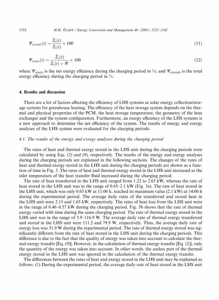
The rates of heat and thermal exergy stored in the LHS unit during the charging periods werecalculated by using Eqs. (2) and (9), respectively. The results of the energy and exergy analysesduring the charging periods are explained in the following sections. The changes of the rates ofheat and thermal exergy stored in the LHS unit during the charging periods are shown as a func-tion of time in Fig. 3. The rates of heat and thermal exergy stored in the LHS unit increased as theinlet temperature of the heat transfer fluid increased during the charging period.
The rate of heat transferred in the LHS unit ranged from 1.22 to 2.63 kW, whereas the rate ofheat stored in the LHS unit was in the range of 0.65–2.1 kW (Fig. 3a). The rate of heat stored inthe LHS unit, which was only 0.65 kW at 11:00 h, reached its maximum value (2.1 kW) at 14:00 hduring the experimental period. The average daily rates of the transferred and stored heat inthe LHS unit were 2.15 and 1.63 kW, respectively. The rates of heat loss from the LHS unit werein the range of 0.46–0.57 kW during the charging period. Fig. 3b shows that the rate of thermalexergy varied with time during the same charging period. The rate of thermal exergy stored in theLHS unit was in the range of 3.9–116.9 W. The average daily rate of thermal exergy transferredand stored in the LHS unit were 111.2 and 79.9 W, respectively. Thus, the average daily rate ofexergy loss was 31.9 W during the experimental period. The rate of thermal exergy stored was sig-nificantly different from the rate of heat stored in the LHS unit during the charging periods. Thisdifference is due to the fact that the quality of energy was taken into account to calculate the ther-mal exergy transfer [Eq. (9)]. However, in the calculation of thermal energy transfer [Eq. (2)], onlythe quantity of the energy was taken into account. In other words, the useless part of the thermalenergy stored in the LHS unit was ignored in the calculation of the thermal exergy transfer.
The differences between the rates of heat and exergy stored in the LHS unit may be explained asfollows. (1) During the experimental period, the average daily rate of heat stored in the LHS unit
0
0.5
1
1.5
2
2.5
3
11 12 13 14 15 16 17
Time, h
Rat
e of
hea
t tra
nsfe
r, W
Transferrred Stored Loss
0
50
100
150
200
11 12 13 14 15 16 17Time, h
Rat
e of
exe
rgy
tran
sfer
, W
Transferred Stored Loss
(a)
(b)
Fig. 3. The rates of heat and thermal exergy stored in the heat storage unit during charging.
H.H. Ozturk / Energy Conversion and Management 46 (2005) 1523–1542 1533
was higher than that of the thermal exergy. Since the rate of exergy depends on the temperature ofthe heat transfer fluid and its surrounding, the rate of exergy increased as the difference betweenthe inlet and outlet temperatures of the heat transfer fluid increased during the charging periods.(2) The rate of exergy transfer is higher at high temperatures than that at low temperatures. (3)Moreover, the percentage increase in the thermal exergy at high temperatures was higher in com-parison with the thermal energy. In this study, it was also found that the percentage increase in thethermal exergy was higher than that of the thermal energy during the charging periods. These re-sults may be simply explained in terms of heat transfer considerations. The possible amount ofthermal energy stored in the LHS unit decreased as the difference between the inlet and outlet tem-peratures of the heat transfer fluid decreased during the charging periods. The percentage decreasein the possible amount of thermal energy stored in the LHS unit was higher in comparison withthe thermal exergy during the charging periods. The differences between the thermal energy andexergy stored in the LHS unit are attributed to the differences in the inlet and outlet temperaturesof the heat transfer fluid and the ambient temperature.
4.2. Energy and exergy efficiency during the charging period
The total and net energy and exergy efficiencies of the heat storage system during the chargingperiod were calculated by using Eqs. (6), (7), (11) and (12), respectively. The changes of the energy
1534 H.H. Ozturk / Energy Conversion and Management 46 (2005) 1523–1542
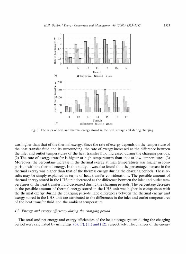
and exergy efficiencies during the experimental period are shown as a function of time in Fig. 4.The energy and exergy efficiencies of the LHS system increased as the inlet temperature of the heattransfer fluid increased.
The total energy efficiency ranged from 53.7% to 79.6%, while the net energy efficiency was inthe range of 22.1–47.9% during the first charging period (Fig. 4a). While the net exergy efficiencyat 11:00 h was only 22.1%, it reached its maximum value (47.9%) at 14:00 h. During the experi-mental period, it was found that the average daily total and net energy efficiencies were 74.3% and40.4%, respectively. On the other hand, the total exergy efficiency ranged from 10.5% to 80.6%,whereas the net exergy efficiency was in the range of 0.2–6.2% during the same charging period(Fig. 4b). The average daily total and net exergy efficiencies were 65.2% and 4.2%, respectively.
When the net energy efficiency is compared with net exergy efficiency during the charging per-iod, the following results can be drawn: (1) The net energy efficiency was always higher than thenet exergy efficiency. This is expected because the total energy content of the hot air used as heattransfer fluid is taken into account in order to calculate the net energy efficiency. In other words,to calculate the net energy efficiency, the quantity of the energy transferred is taken into account,and the quality of the energy transferred is neglected. (2) For all charging periods, similar resultswere obtained in terms of the net energy efficiency of the LHS system. The average daily netenergy efficiency of the LHS system remained nearly constant (approximately 75%) during thecharging periods. The net energy efficiency of the heat storage system did not change much during
0
20
40
60
80
100
11 12 13 14 15 16 17
Time, h
Ene
rgy
effi
cien
cy, %
Total efficiency Net efficiency
0
20
40
60
80
100
11 12 13 14 15 16 17
Time, h
Tot
al e
xerg
y ef
fici
ency
, %
0
2
4
6
8
10
Net
exe
rgy
effi
cien
cy, %
Net efficiency Total efficiency
(a)
(b)
Fig. 4. The change of efficiency of the latent heat storage system during the charging period: (a) energy efficiency;
(b) exergy efficiency.
H.H. Ozturk / Energy Conversion and Management 46 (2005) 1523–1542 1535
the charging periods. However, the net exergy efficiency of the LHS system changed during thecharging periods. The above results indicate that the net exergy efficiency of the LHS systemwas always lower than the net energy efficiency at the higher temperatures. (3) It was found thatthe average net exergy efficiency was only 4.2% during the charging period. This result indicatesthat the heat storage system investigated in this study is inefficient in terms of the exergy efficiency.
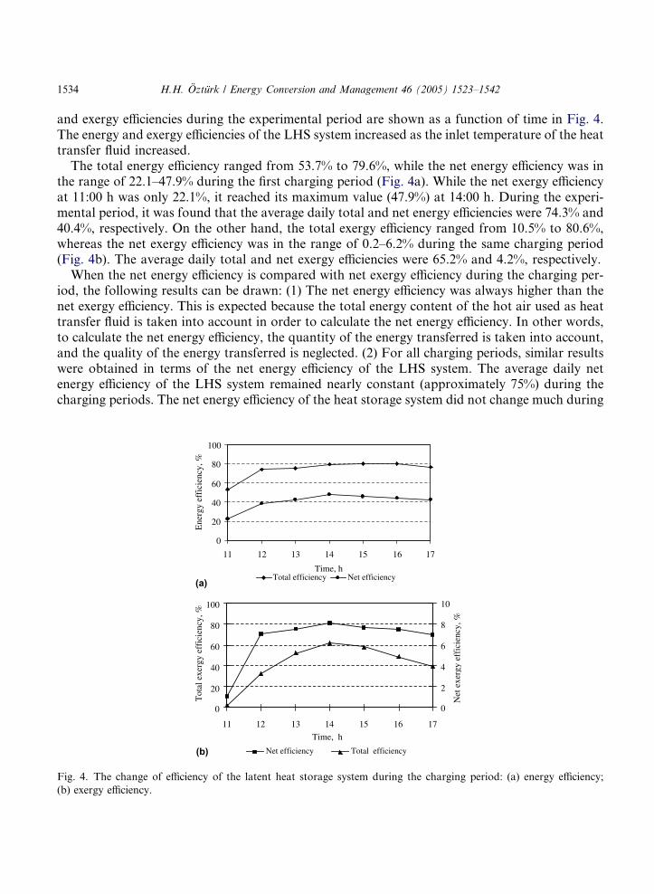
The effect of the temperature difference of the heat transfer fluid at the inlet and outlet of theLHS unit on the computed values of the net energy and exergy efficiencies during the chargingperiod is presented in Fig. 5. A linear regression of the plotted points was used to find the rela-tionship between the net energy and exergy efficiencies and temperature difference in terms ofintercept (%) and slope (%/K). The temperature difference in the LHS unit was observed to havemuch influence on the net energy and exergy efficiencies of the LHS system, their values beinghigher for higher temperature differences. In other words, the net energy and exergy efficienciesincreased as the temperature difference increased during the charging period. Initially, the temper-ature difference of the heat transfer fluid at the inlet and outlet of the LHS unit was small, but itincreased with time. It was obtained that the highest temperature difference was 40 K in the LHSunit during the charging period. While the temperature difference was only 16.1 K in the morning,it reached 40 K in the early afternoon. For the period of time covered by Fig. 4, the average tem-perature difference in the LHS unit was 31.2 K. The net energy and exergy efficiencies (%) as afunction of temperature difference (K) during the charging period were (Fig. 5):
gcðnetÞ ¼ 5:2961þ 1:1243DT R2 ¼ 0:98 ð13Þ
WcðnetÞ ¼ �4:0143þ 0:2629DT R2 ¼ 0:96 ð14Þ
The linear regression coefficient of determination (R2) for the net energy and exergy efficiencieswere 98% and 96%, respectively. The results of the variance analysis (ANOVA) for the relation-ships between the net energy/exergy efficiency and temperature difference are given in Table 1. Therelationships between the net energy/exergy efficiency and temperature difference are statisticallyimportant (P = 2.59 · 10�5 and P = 1.29 · 10�4) at the 95% probability level. For that reason,the obtained regression equations (Eqs. (13) and (14)) represent the relationships between they = 1.1243x + 5.2961R2 = 0.9775
y = 0.2629x - 4.0143R2 = 0.9574
0
10
20
30
40
50
60
0 10 20 30 40 50
Temperature difference, K
Eff
icie
ncy,
%
Energy efficiency Exergy efficiency
Fig. 5. Effect of temperature difference on efficiency of the latent heat storage system.
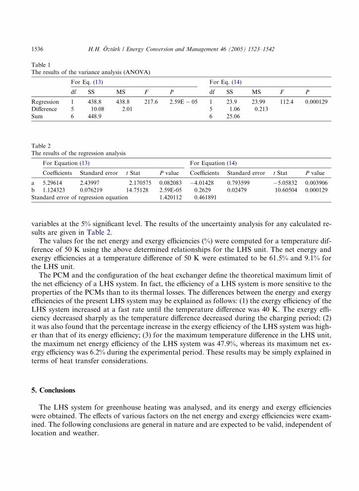
Table 1
The results of the variance analysis (ANOVA)
For Eq. (13) For Eq. (14)
df SS MS F P df SS MS F P
Regression 1 438.8 438.8 217.6 2.59E � 05 1 23.9 23.99 112.4 0.000129
Difference 5 10.08 2.01 5 1.06 0.213
Sum 6 448.9 6 25.06
Table 2
The results of the regression analysis
For Equation (13) For Equation (14)
Coefficients Standard error t Stat P value Coefficients Standard error t Stat P value
a 5.29614 2.43997 2.170575 0.082083 �4.01428 0.793599 �5.05832 0.003906
b 1.124323 0.076219 14.75128 2.59E-05 0.2629 0.02479 10.60504 0.000129
Standard error of regression equation 1.420112 0.461891
1536 H.H. Ozturk / Energy Conversion and Management 46 (2005) 1523–1542
variables at the 5% significant level. The results of the uncertainty analysis for any calculated re-sults are given in Table 2.
The values for the net energy and exergy efficiencies (%) were computed for a temperature dif-ference of 50 K using the above determined relationships for the LHS unit. The net energy andexergy efficiencies at a temperature difference of 50 K were estimated to be 61.5% and 9.1% forthe LHS unit.
The PCM and the configuration of the heat exchanger define the theoretical maximum limit ofthe net efficiency of a LHS system. In fact, the efficiency of a LHS system is more sensitive to theproperties of the PCMs than to its thermal losses. The differences between the energy and exergyefficiencies of the present LHS system may be explained as follows: (1) the exergy efficiency of theLHS system increased at a fast rate until the temperature difference was 40 K. The exergy effi-ciency decreased sharply as the temperature difference decreased during the charging period; (2)it was also found that the percentage increase in the exergy efficiency of the LHS system was high-er than that of its energy efficiency; (3) for the maximum temperature difference in the LHS unit,the maximum net energy efficiency of the LHS system was 47.9%, whereas its maximum net ex-ergy efficiency was 6.2% during the experimental period. These results may be simply explained interms of heat transfer considerations.
5. Conclusions
The LHS system for greenhouse heating was analysed, and its energy and exergy efficiencieswere obtained. The effects of various factors on the net energy and exergy efficiencies were exam-ined. The following conclusions are general in nature and are expected to be valid, independent oflocation and weather.
H.H. Ozturk / Energy Conversion and Management 46 (2005) 1523–1542 1537
5.1. Greenhouse heating with solar energy
The use of solar energy for greenhouse heating has gained an increasing acceptance during recentyears. The main problem is related to the selection and sizing, or more appropriately the passive oractive technology, for the specific application. Active solar systems applied to greenhouses can sup-ply a significant part of the heating requirements. However, there are some problems related to thecost of the heat collection unit, of the occupied land, the backup system and the heat storage meth-ods. A significant investment cost is necessary with active solar systems; especially for the metallicglazed collectors used as the heat collection unit. The investment cost of the present system was$US 3500. Basic and applied research and development is needed to improve performance analysis,reduce operation cost of installed systems, assure their long term trouble free operation and im-prove their efficiency. The economics and thermal efficiency of each new system must be carefullyevaluated in a total system context; otherwise, it is not certain if a concept has sufficient merit towarrant further development for solar application. In each application, system studies with realisticcost estimates are needed to define the economic worth of storage in the intermediate temperaturerange. An active solar system for greenhouse heating can be coupled with a heat pump in order toincrease its efficiency. In addition, the storage volume and capacity of the heat storage materialshould be chosen carefully. Research and development on active solar systems for greenhouse heat-ing have given a certain number of technical solutions aimed at overcoming the above problems.
5.2. Heat storage material for greenhouse heating
For intermediate temperature sensible heat storage, the commercially available liquids are generallyexpensive. Research directed toward improving the lifetime of sensible heat storage fluids could be use-ful. Solidmaterials are economicallymore attractive for high temperature storage than fluids, and theirvolume requirements are nearly comparable. However, research and development are needed to findheat transfer fluids that can be used in direct contact with the solids over long time periods. Develop-ment and low cost containment and direct heat technology could significantly reduce the cost of green-house heating systems with solar energy in the intermediate temperature range. Direct contact betweenthe solid storage media and a heat transfer fluid is vital to minimise the cost of heat exchange in a sen-sible heat storage system. If the same heat exchanger is used for the charging and discharging proc-esses, considerable attention should be given to the design of the heat exchanger. In this case,technical limitations should be taken into account. LHS using PCMs, in general, provides much higherenergy storage density than systems using sensible heat storage. High energy storage densities over anarrow temperature range make PCMs attractive for greenhouse heating. There are problems withrepeatable cycling, heat transfer rate and containment that need to be solved before LHS systemscan become commercially and economically viable for intermediate temperatures. Future studiesshould focus on: LHS for greenhouse heating and modelling the efficiency of the heat storage systems.Such experimental studies will be very useful to optimise the management of the heat storage systems.
5.3. Evaluation of the system efficiency
The results of this study show that the difference between the results of energy and exergyanalyses is significant. Since exergy is a measure of the quality of energy, exergy efficiency is
1538 H.H. Ozturk / Energy Conversion and Management 46 (2005) 1523–1542
more significant than energy efficiency, and exergy analysis should be considered in the evalua-tion and comparison of thermal energy storage systems. Exergy analysis clearly takes into ac-count the loss of availability of heat in storage operations, and hence, it more correctlyreflects the thermodynamic and economic value of the storage operation. Optimisation of thedesign and exploitation of thermal energy storage systems can be made by means of exergy anal-ysis. When optimising the thermodynamic efficiency of a thermal energy storage system, bothdesign and operational parameters must be considered. The real purpose of a thermal energystorage system is not to store energy, but to store exergy. According to the results of the exper-iments, LHS systems are inherently inefficient devices in terms of the exergy efficiency. Exergyloss and auxiliary energy consumptions for the charging and discharging processes could be re-duced to improve the exergy efficiency of the thermal energy storage systems for a particularapplication. The unit should be capable of receiving energy at the maximum rate without exces-sive driving forces. Analyses of the thermal performance of systems, the costs of solar equipmentand the costs of auxiliary energy systems can be used to determine the optimum size of the sys-tem components for a particular application. Exergy analysis is essential to cost effective designand management of the thermal energy storage systems. Therefore, exergy analysis must be usedto design thermal energy storage systems with the highest possible thermodynamic efficiencies. Inconclusion, the charging and discharging processes of a thermal energy storage system must beanalysed in order to optimise system efficiency.
Appendix A
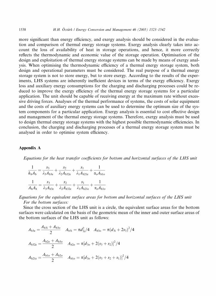
Equations for the heat transfer coefficients for bottom and horizontal surfaces of the LHS unit
1
kbAb
¼ s3k3Ab3e
þ s2k2Ab32e
þ s1k1Ab21e
þ 1
aoAb1o
1
AhAh
¼ s3k3Ah3e
þ s2k2Ah32e
þ s1k1Ah21e
þ 1
aoAh1o
Equations for the equivalent surface areas for bottom and horizontal surfaces of the LHS unitFor the bottom surfaces:
Since the cross section of the LHS unit is a circle, the equivalent surface areas for the bottomsurfaces were calculated on the basis of the geometric mean of the inner and outer surface areas ofthe bottom surfaces of the LHS unit as follows:
Ab3e ¼Ab3i þ Ab3o
2Ab3i ¼ pd2
3i=4 Ab3o ¼ pðd3i þ 2s3Þ2=4
Ab32e ¼Ab2o þ Ab3o
2Ab2o ¼ p½d3o þ 2ðs3 þ s2Þ�2=4
Ab21e ¼Ab1o þ Ab2o
2Ab1o ¼ p½d3o þ 2ðs3 þ s2 þ s1Þ�2=4
H.H. Ozturk / Energy Conversion and Management 46 (2005) 1523–1542 1539
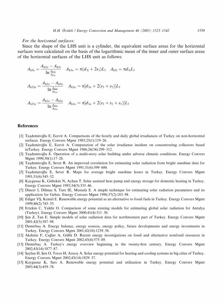
For the horizontal surfaces:
Since the shape of the LHS unit is a cylinder, the equivalent surface areas for the horizontalsurfaces were calculated on the basis of the logarithmic mean of the inner and outer surface areasof the horizontal surfaces of the LHS unit as follows:
Ah3e ¼Ah3o � Ah3i
ln Ah3o
Ah3i
Ah3o ¼ pðd3i þ 2s3ÞL3 Ah3i ¼ pd3iL3
Ah32e ¼Ah2o � Ah3o
ln Ah2o
Ah3o
Ah2o ¼ p½d3o þ 2ðs3 þ s2Þ�L3
Ah21e ¼Ah1o � Ah2o
ln Ah1o
Ah2o
Ah1o ¼ p½d3o þ 2ðs3 þ s2 þ s1Þ�L3
References
[1] Tas�demiroglu E, Ecevit A. Comparisons of the hourly and daily global irradiances of Turkey on non-horizontal
surfaces. Energy Convers Mgmt 1985;25(1):119–26.
[2] Tas�demiroglu E, Ecevit A. Computation of the solar irradiance incident on concentrating collectors based
inTurkey. Energy Convers Mgmt 1986;26(34):299–312.
[3] Tas�demiroglu E. Operation of a multi-story solar building under adverse climatic conditions. Energy Convers
Mgmt 1990;30(1):17–28.
[4] Tas�demiroglu E, Sever R. An improved correlation for estimating solar radiation from bright sunshine data for
Turkey. Energy Convers Mgmt 1991;31(6):599–600.
[5] Tas�demiroglu E, Sever R. Maps for average bright sunshine hours in Turkey. Energy Convers Mgmt
1991;31(6):545–52.
[6] Kaygusuz K, Gultekin N, Ayhan T. Solar assisted heat pump and energy storage for domestic heating in Turkey.
Energy Convers Mgmt 1993;34(5):335–46.
[7] Dincer I, Dilmac S, Ture IE, Mustafa E. A simple technique for estimating solar radiation parameters and its
application for Gebze. Energy Convers Mgmt 1996;37(2):183–98.
[8] Ediger VS�, Kentel E. Renewable energy potential as an alternative to fossil fuels in Turkey. Energy Convers Mgmt
1999;40(2):743–55.
[9] Ertekin C, Yaldiz O. Comparison of some existing models for estimating global solar radiation for Antalya
(Turkey). Energy Convers Mgmt 2000;41(4):311–30.
[10] S�en Z, Tan E. Simple models of solar radiation data for northwestern part of Turkey. Energy Convers Mgmt
2001;42(5):587–98.
[11] Demirbas� A. Energy balance, energy sources, energy policy, future developments and energy investments in
Turkey. Energy Convers Mgmt 2001;42(10):1239–58.
[12] Akdeniz F, Caglar A, Gullu D. Recent energy investigations on fossil and alternative nonfossil resources in
Turkey. Energy Convers Mgmt 2002;43(4):575–89.
[13] Demirbas� A. Turkey�s energy overview beginning in the twenty-first century. Energy Convers Mgmt
2002;43(14):1877–87.
[14] S�aylan H, S�en O, Toros H, Arısoy A. Solar energy potential for heating and cooling systems in big cities of Turkey.
Energy Convers Mgmt 2002;43(14):1829–37.
[15] Kaygusuz K, Sarı A. Renewable energy potential and utilization in Turkey. Energy Convers Mgmt
2003;44(3):459–78.
1540 H.H. Ozturk / Energy Conversion and Management 46 (2005) 1523–1542
[16] Kaygusuz K. Energy policy and climate change in Turkey. Energy Convers Mgmt 2003;44(10):1671–88.
[17] Ocak M, Ocak Z, Bilgen S, Keles� S, Kaygusuz K. Energy utilization, environmental pollution and renewable
energy sources in Turkey. Energy Convers Mgmt 2004;45(6):845–64.
[18] Hepbasli A, Akdemir O. Energy and exergy analysis of a ground source (geothermal) heat pump system. Energy
Convers Mgmt 2004;45(5):737–43.
[19] Ultanır, M. Potential of new and renewable energy sources in long-term utilisation for Turkish rural areas. In:
Proceedings of AGENG 94 international conference on agricultural engineering, 29th August–1st September,
Milano, Italy, 1994. p. 822–8.
[20] Kaygusuz K. The viability of thermal energy storage. Energy Sources 1999;21(8):745–55.
[21] Tahat MA, Babus Hag RF, Callagfan PWO, Probert SD. Design feasibility of an intermittent domestic energy
store. Appl Energy 1995;51(3):277–90.
[22] Fath HES. Heat exchanger performance for latent heat thermal energy storage system. Energy Convers Mgmt
1991;31(2):149–55.
[23] Hasan A. Thermal energy storage system with stearic acid as phase change material. Energy Convers Mgmt
1994;35(10):843–56.
[24] Tayeb AM. Organic-inorganic mixtures for solar energy storage systems. Energy Convers Mgmt
1995;36(10):969–74.
[25] Paksoy HO. Determining thermal properties of heat storage materials using the twin bath method. Energy
Convers Mgmt 1996;37(3):261–8.
[26] Buddhi D, Murthy VVS. Comparison of using thermocouple and optical fibre to study the solid-liquid boundary
in phase change materials. Energy Convers Mgmt 1996;37(5):637–9.
[27] Brousseau P, Lacroix M. Study of the thermal performance of a multi-layer PCM storage unit. Energy Convers
Mgmt 1996;37(5):599–609.
[28] Esen M, Ayhan T. Development of a model compatible with solar assisted cylindrical energy storage tank and
variation of stored energy with time for different phase change materials. Energy Convers Mgmt 1996;37(12):
1775–85.
[29] Kurklu A. Thermal performance of a tapered store containing tubes of phase change material: cooling cycle.
Energy Convers Mgmt 1997;38(4):333–40.
[30] Royon L, Guiffant LG, Flaud P. Investigation of heat transfer in a polymeric phase change material for low level
heat storage. Energy Convers Mgmt 1997;38(6):517–24.
[31] Lacroix M, Duong T. Experimental improvements of heat transfer in a latent heat thermal energy storage unit with
embedded heat sources. Energy Convers Mgmt 1998;39(8):703–16.
[32] Hasnain SM. Review on sustainable thermal energy storage technologies, Part I: heat storage materials and
techniques. Energy Convers Mgmt 1998;39(11):1127–38.
[33] Ismail KAR, Goncalves MM. Thermal performance of a PCM storage unit. Energy Convers Mgmt
1999;40(2):115–38.
[34] Kaygusuz K, Ayhan T. Experimental and theoretical investigation of combined solar heat pump system for
residential heating. Energy Convers Mgmt 1999;40(13):1377–96.
[35] Ismail KAR, Henrıquez JR. Solidification of PCM inside a spherical capsule. Energy Convers Mgmt
2000;41(2):173–87.
[36] Lacroix M. Contact melting of a phase change material inside a heated parallelepipedic capsule. Energy Convers
Mgmt 2001;42(1):35–47.
[37] El Qarnia H, Lacroix M, Mercadier Y. Use of a phase change material to prevent frosting in a compact crossflow
air exchanger. Energy Convers Mgmt 2001;42(10):1277–96.
[38] Xiao M, Feng B, Gong K. Preparation and performance of shape stabilized phase change thermal storage
materials with high thermal conductivity. Energy Convers Mgmt 2002;43(1):103–8.
[39] Sarı A, Kaygusuz K. Thermal performance of palmitic acid as a phase change energy storage material. Energy
Convers Mgmt 2002;43(6):863–76.
[40] Ismail KAR, Henrıquez JR. Parametric study on composite and PCM glass systems. Energy Convers Mgmt
2002;43(7):973–93.
H.H. Ozturk / Energy Conversion and Management 46 (2005) 1523–1542 1541
[41] He B, Setterwall F. Technical grade paraffin waxes as phase change materials for cool thermal storage and cool
storage systems capital cost estimation. Energy Convers Mgmt 2002;43(13):1709–23.
[42] Sarı A, Kaygusuz K. Thermal and heat transfer characteristics in a latent heat storage system using lauric acid.
Energy Convers Mgmt 2002;43(18):2493–507.
[43] Simard AP, Lacroix M. Study of the thermal behavior of a latent heat cold storage unit operating under frosting
conditions. Energy Convers Mgmt 2003;44(18):1605–24.
[44] Sarı A. Thermal reliability test of some fatty acids as PCMs used for solar thermal latent heat storage applications.
Energy Convers Mgmt 2003;44(13):2277–87.
[45] El Qarnia H. Theoretical study of transient response of a rectangular latent heat thermal energy storage system
with conjugate forced convection. Energy Convers Mgmt 2004;45(9–10):1537–51.
[46] Farid MM, Khudhair AM, Ali S, Razack K, Al-Hallaj S. A review on phase change energy storage: materials and
applications. Energy Convers Mgmt 2004;45(9–10):1597–615.
[47] Sarı A, Baran G. Phase change and heat transfer characteristics of a eutectic mixture of palmitic and stearic acids
as PCM in a latent heat storage system. Energy Convers Mgmt 2003;44(20):3227–46.
[48] Sarı A. Form-stable paraffin/high density polyethylene composites as solid–liquid phase change material for
thermal energy storage: preparation and thermal properties. Energy Convers Mgmt 2004;45(13–14):2033–42.
[49] Khudhair AM, Farid MM. A review on energy conservation in building applications with thermal storage by
latent heat using phase change materials. Energy Convers Mgmt 2004;45(2):263–75.
[50] Brousseau P, Lacroix M. Numerical simulation of a multi-layer latent heat thermal energy storage system. Int J
Energy Res 1998;22:1–15.
[51] Branden GVD, Hesius M, Dhaeseleer W. Comparisons of heat storage systems employing sensible and latent heat.
Int J Energy Res 1999;23:605–24.
[52] Wang J, Chen G, Jiang H. Theoretical study on a novel phase change process. Int J Energy Res 1999;23:287–94.
[53] Wang J, Chen G, Zheng F. Study on phase change temperature distributions of composite PCMs in thermal
energy storage systems. Int J Energy Res 1999;23:277–85.
[54] Sarı A, Kaygusuz K. Energy and exergy calculations of latent heat energy storage systems. Energy Sources
2000;22(2):117–26.
[55] Sarı A, Kaygusuz K. Thermal energy storage system using some fatty acids as latent heat energy storage materials.
Energy Sources 2001;23(1):275–85.
[56] Ozturk HH, Bas�cetincelik A. Thermal energy storage techniques. The Union of Turkish Chambers of Agriculture,
Publication Number 230, Ankara; 2002 [in Turkish].
[57] Ozturk HH, Bas�cetincelik A. Energy and exergy analyses for the evaluation of the efficiency of solar thermal
energy storage systems. In: Proceedings of national symposium on solar energy systems, Mersin, Turkey, 2003. p.
102–16 [in Turkish].
[58] El-Dessouky H, Al-Juwayhel F. Effectiveness of a thermal energy storage system using phase change materials.
Energy Convers Mgmt 1997;38(6):601–17.
[59] Hawlader MNA, Uddin MS, Khin MM. Microencapsulated PCM thermal energy storage system. Appl Energy
2003;74(1):195–202.
[60] Ozturk HH. The research on storage of solar energy in phase change material (PCM) for greenhouse heating. PhD
thesis, Department of Agricultural Machinery Institute of Natural and Applied Sciences, University of Cukurova,
Turkey, 1997 [in Turkish].
[61] Rosen MA, Hooper FC, Barbaris LN. Exergy analysis for the evaluation of the performance of closed thermal
energy storage systems. Trans ASME, J Solar Energy Eng 1988;110:255–61.
[62] Rosen MA. Appropriate thermodynamic performance measures for closed systems for thermal energy storage.
ASME J Solar Energy Eng 1992;114:100–5.
[63] Gunnewiek LH, Nguyen S, Rosen MA. Evaluation of the optimum discharge period for closed thermal energy
storages using energy and exergy analyses. Solar Energy 1993;51:39–43.
[64] Dincer I, Dost S, Li X. Performance analysis of sensible heat storage systems for thermal applications. Int J Energy
Res 1997;21:1157–71.

1542 H.H. Ozturk / Energy Conversion and Management 46 (2005) 1523–1542
[65] Dincer I. Evaluation and selections of energy storage systems for thermal applications. Int J Energy Res
1999;23:1017–28.
[66] Ozturk HH, Bas�cetincelik A. Energy and exergy efficiency of a packed-bed heat storage unit for greenhouse
heating. Biosyst Eng 86(2):231–45.