Embed Size (px)
Citation preview
U.P.B. Sci. Bull., Series B, Vol. 79, Iss. 3, 2017 ISSN 1454-2331
EXPERIMENTAL AND FINITE ELEMENT ANALYSIS OF
MULTILAYERED HONEYCOMB COMPOSITE MATERIAL
SUBJECT TO STATIC LOADING
Cormos RAUL1, Horia-Alexandru PETRESCU2, Anton HADAR3
A set of four different multilayered honeycomb composite materials were
created for the purpose of determine their mechanical properties under static
compressive loading. Thus, the four different configurations were subjected to a
specific compression test and afterwards retested, in the same manner but through
numerical virtualization.
Validation of these results allows the use of such finite element models in
widespread areas of engineering such as aeronautics, but not limited thereto.
Keywords: honeycomb structure, numerical virtualization, composite materials,
numerical validation.
1. Introduction
Sandwich structures are composite materials with high strength and low
mass. This combination of mechanical properties makes them highly used in
many areas of mechanical engineering, such as: aerospace, naval and automobile
industry, as well on civilian and military. The result of the usage of sandwich
structures, in these areas of mechanical engineering, are stronger and lighter
structural components [4, 5].
The most important industrial applications of honeycomb sandwich
structures can be found in the aerospace industry. Such applications as helicopter
rotor blades, hall of the aircraft, aircraft engine turbine noise reduction, or
spacecraft structures represents the highest performance demanding areas where
the usage of honeycomb sandwich structures is vital. A study about their
applications for the Boeing 737-800 interiors is reported in [13].
L. J. Gibson [1] and J. R. Vinson [3], have demonstrated that the most
important load bearing component for a statically loaded honeycomb sandwich
1 Faculty of Applied Chemistry and Materials Science, University POLITEHNICA of Bucharest,
Romania, e-mail: [email protected] 2 Faculty of Applied Chemistry and Materials Science, University POLITEHNICA of Bucharest,
Romania 3 Faculty of Applied Chemistry and Materials Science, University POLITEHNICA of Bucharest,
Romania
122 Cormos Raul, Horia-Alexandru Petrescu, Anton Hadar
structure is the core component. Furthermore Gibson [1] and Bruhn [7] have
numerically determined the mechanical properties of the honeycomb sandwich
structure based on the honeycomb cell configuration and the material used for the
honeycomb core. Also, it presented that a regular cell sized honeycomb structure
has isotropic mechanical properties in the tangential direction of the cell, if the
cell structure is made by evenly sized cells.
The loading curve of a honeycomb core, axially loaded, is independent by
the material from which the core is made, or the cell size.
The failure of honeycomb cores statically loaded on the transversal
direction (bending or shear) of the cell occurs by the appearance of yield points on
the intersection of the cells. In [9], the plastic collapse of inclined walls in the Y-
direction due to plastic hinges formation is depicted.
For a honeycomb sandwich structure subjected to compression, the failure
of the core is caused by the buckling effect of the cell walls, not by compression
stress failure. An approach, based on an elasticity solution that matches the
deformations of individual face-sheets, focused on the calculation of stresses and
predict failure in sandwich ramp-down regions under bending loads is presented
in [10].
Out-of-plane compressive tests on bare honeycombs were carried out in
[17] resulting that the compressive stress increases almost linearly with the strain
due to the elastic bending of the thin cell walls.
The multitudes of cores used in the sandwich structures, gives different
mechanical properties alongside their thickness, for these materials. In the last
decades, strong efforts have been made to develop nonconventional cores for
sandwich structures. These resulted in new mechanical properties such as negative
Poisson’s ratio [6].
Thus, development of nonconventional sandwich structures, such as
multilayered honeycomb composite materials, represents a strategic line of
development in the area of future composite materials.
For mechanical applications, any load is transmitted through contact.
There is an increasing practical interest in the application of cellular
materials (such as honeycombs and foams) being used in passive vehicle safety
systems as crash energy absorber elements [14-16].
Analytical methods have been developed to describe the impact
phenomena, for regularly sized bodies. These methods are not suited to describe
the contact phenomena for bodies with highly complex contact geometry.
With the development of the finite element method (FEM) new
computational methods were introduced which allow the numerical simulation of
the contact phenomena for complex contact areas between bodies. One such
method is the penalty method presented by P. Wriggers [2, 8], which represents
the most used method for finite element simulation in contact mechanics. This
Experimental and finite element analysis of multilayered honeycomb composite material (…) 123
energetic method allows the determination of contact force between the two
bodies, considering the elasticity of the bodies.
Tao Zhu et al. in [11] have used FEM to predict the local buckling
behavior and the debonding propagation in honeycomb sandwich structures.
In order to reflect microscopic structure and deformation of the unit cell,
periodic boundary conditions should be applied on unit cell, as is stated in [12],
but not the case of this study due to the mesoscale of our study.
The main purpose of this article is to validate the finite element analysis of
four multilayered honeycomb composite material configurations subjected to
static loading, in the linear elastic domain of the material.
2. Multilayered honeycomb composite material description
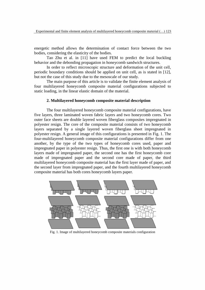
The four multilayered honeycomb composite material configurations, have
five layers, three laminated woven fabric layers and two honeycomb cores. Two
outer face sheets are double layered woven fiberglass composites impregnated in
polyester resign. The core of the composite material consists of two honeycomb
layers separated by a single layered woven fiberglass sheet impregnated in
polyester resign. A general image of this configurations is presented in Fig. 1. The
four-multilayered honeycomb composite material configurations differ from one
another, by the type of the two types of honeycomb cores used, paper and
impregnated paper in polyester resign. Thus, the first one is with both honeycomb
layers made of impregnated paper, the second one has the first honeycomb core
made of impregnated paper and the second core made of paper, the third
multilayered honeycomb composite material has the first layer made of paper, and
the second layer from impregnated paper, and the fourth multilayered honeycomb
composite material has both cores honeycomb layers paper.
Fig. 1. Image of multilayered honeycomb composite materials configuration
124 Cormos Raul, Horia-Alexandru Petrescu, Anton Hadar
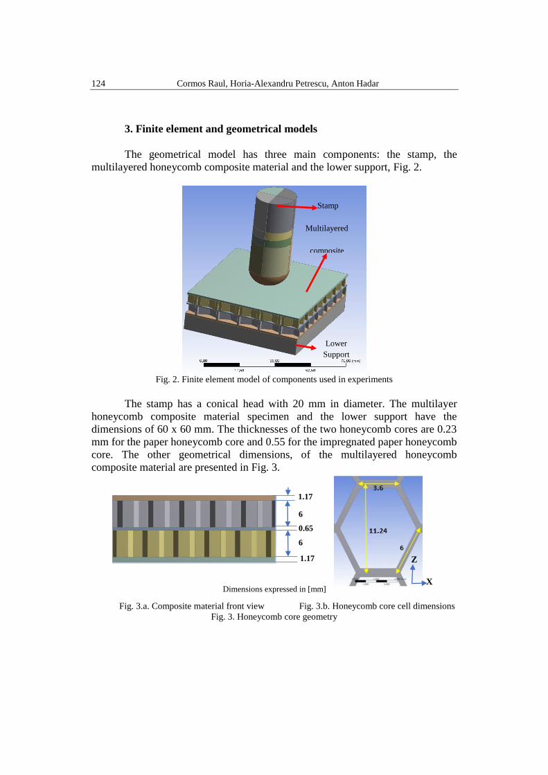
3. Finite element and geometrical models
The geometrical model has three main components: the stamp, the
multilayered honeycomb composite material and the lower support, Fig. 2.
Fig. 2. Finite element model of components used in experiments
The stamp has a conical head with 20 mm in diameter. The multilayer
honeycomb composite material specimen and the lower support have the
dimensions of 60 x 60 mm. The thicknesses of the two honeycomb cores are 0.23
mm for the paper honeycomb core and 0.55 for the impregnated paper honeycomb
core. The other geometrical dimensions, of the multilayered honeycomb
composite material are presented in Fig. 3.
Fig. 3.a. Composite material front view Fig. 3.b. Honeycomb core cell dimensions
Fig. 3. Honeycomb core geometry
Stamp
Multilayered
composite
material
Lower
Support
1.17
6
0.65
6
1.17 Z
X Dimensions expressed in [mm]
Experimental and finite element analysis of multilayered honeycomb composite material (…) 125
The lower support, on witch multilayered honeycomb composite material is
placed, has a hole in the center of 40 mm in diameter. For these multilayer
honeycomb composite materials, the position of the two honeycomb layers are not
known to each other, four geometrical models were considered, based on the
position of the honeycomb layers.
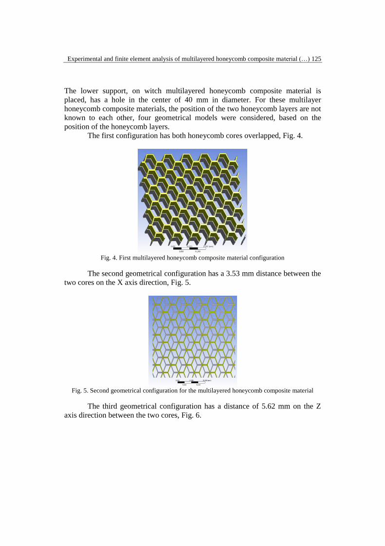
The first configuration has both honeycomb cores overlapped, Fig. 4.
Fig. 4. First multilayered honeycomb composite material configuration
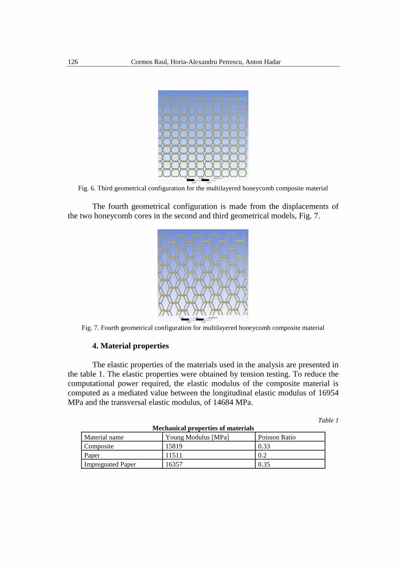
The second geometrical configuration has a 3.53 mm distance between the
two cores on the X axis direction, Fig. 5.
Fig. 5. Second geometrical configuration for the multilayered honeycomb composite material
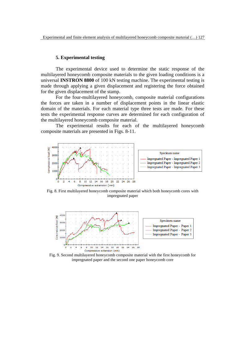
The third geometrical configuration has a distance of 5.62 mm on the Z
axis direction between the two cores, Fig. 6.
126 Cormos Raul, Horia-Alexandru Petrescu, Anton Hadar
Fig. 6. Third geometrical configuration for the multilayered honeycomb composite material
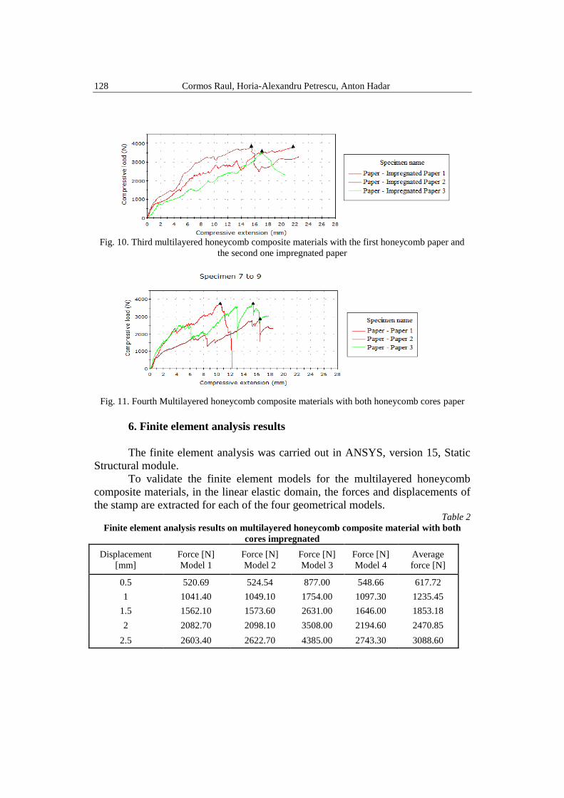
The fourth geometrical configuration is made from the displacements of
the two honeycomb cores in the second and third geometrical models, Fig. 7.
Fig. 7. Fourth geometrical configuration for multilayered honeycomb composite material
4. Material properties
The elastic properties of the materials used in the analysis are presented in
the table 1. The elastic properties were obtained by tension testing. To reduce the
computational power required, the elastic modulus of the composite material is
computed as a mediated value between the longitudinal elastic modulus of 16954
MPa and the transversal elastic modulus, of 14684 MPa.
Table 1
Mechanical properties of materials
Material name Young Modulus [MPa] Poisson Ratio
Composite 15819 0.33
Paper 11511 0.2
Impregnated Paper 16357 0.35
Experimental and finite element analysis of multilayered honeycomb composite material (…) 127
5. Experimental testing
The experimental device used to determine the static response of the
multilayered honeycomb composite materials to the given loading conditions is a
universal INSTRON 8800 of 100 kN testing machine. The experimental testing is
made through applying a given displacement and registering the force obtained
for the given displacement of the stamp.
For the four-multilayered honeycomb, composite material configurations
the forces are taken in a number of displacement points in the linear elastic
domain of the materials. For each material type three tests are made. For these
tests the experimental response curves are determined for each configuration of
the multilayered honeycomb composite material.
The experimental results for each of the multilayered honeycomb
composite materials are presented in Figs. 8-11.
Fig. 8. First multilayered honeycomb composite material which both honeycomb cores with
impregnated paper
Fig. 9. Second multilayered honeycomb composite material with the first honeycomb for
impregnated paper and the second one paper honeycomb core
128 Cormos Raul, Horia-Alexandru Petrescu, Anton Hadar
Fig. 10. Third multilayered honeycomb composite materials with the first honeycomb paper and
the second one impregnated paper
Fig. 11. Fourth Multilayered honeycomb composite materials with both honeycomb cores paper
6. Finite element analysis results
The finite element analysis was carried out in ANSYS, version 15, Static
Structural module.
To validate the finite element models for the multilayered honeycomb
composite materials, in the linear elastic domain, the forces and displacements of
the stamp are extracted for each of the four geometrical models. Table 2
Finite element analysis results on multilayered honeycomb composite material with both
cores impregnated
Displacement
[mm]
Force [N]
Model 1
Force [N]
Model 2
Force [N]
Model 3
Force [N]
Model 4
Average
force [N]
0.5 520.69 524.54 877.00 548.66 617.72
1 1041.40 1049.10 1754.00 1097.30 1235.45
1.5 1562.10 1573.60 2631.00 1646.00 1853.18
2 2082.70 2098.10 3508.00 2194.60 2470.85
2.5 2603.40 2622.70 4385.00 2743.30 3088.60
Experimental and finite element analysis of multilayered honeycomb composite material (…) 129
The value of the forces, for a given displacement of the stamp, is computed as an
average of the reaction forces obtained for the four geometrical models for that
displacement. The finite element simulation results are presented in the tables 2-5.
Table 3
Finite element analysis results on multilayered honeycomb composite material with the first
core impregnated paper in the second paper
Displacement
[mm]
Force [N]
Model 1
Force [N]
Model 2
Force [N]
Model 3
Force [N]
Model 4
Average
force [N]
0.2 207.19 208.74 347.74 225.08 247.19
0.4 414.38 417.47 695.48 450.17 494.38
0.6 621.57 626.20 1043.20 675.25 741.56
0.8 828.76 834.94 1391.00 900.34 988.76
1 1035.90 1043.70 1738.70 1125.40 1235.93
Table 4
Finite element analysis results on multilayered honeycomb composite material with the first
corer paper in the second impregnated paper
Displacement
[mm]
Force [N]
Model 1
Force [N]
Model 2
Force [N]
Model 3
Force [N]
Model 4
Average
force [N]
0.2 204.36 205.73 341.48 160.75 228.08
0.4 408.71 411.46 682.95 321.49 456.15
0.6 613.07 617.19 1024.40 482.24 684.23
0.8 817.43 822.92 1365.90 642.98 912.31
1 1021.80 1028.60 1707.40 803.73 1140.38
Table 5
Finite element analysis results on multilayered honeycomb composite material which both
cores paper
Displacement
[mm]
Force [N]
Model 1
Force [N]
Model 2
Force [N]
Model 3
Force [N]
Model 4
Average
force [N]
0.1 101.62 102.31 169.18 106.99 120.03
0.2 203.24 204.61 338.37 213.98 240.05
0.3 304.86 306.92 507.55 320.96 360.07
0.375 381.08 383.65 634.44 401.21 450.10
7. Comparative analysis
To compare the experimental and finite element analysis results, force-
displacement graphs were made for each material multilayered honeycomb
130 Cormos Raul, Horia-Alexandru Petrescu, Anton Hadar
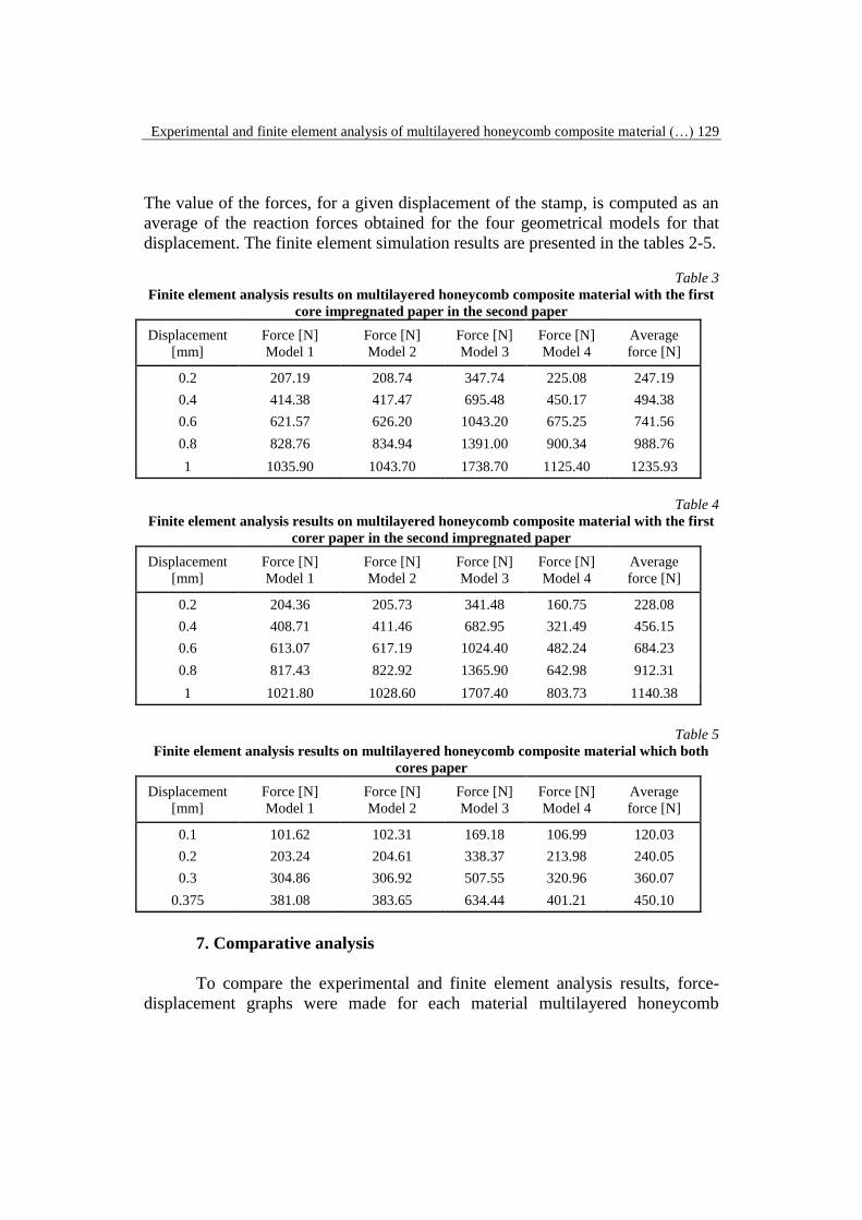
composite material configuration, in the linear elastic domain. These results are
presented in Figs. 12-15.
Fig. 12. Comparative analysis results on the first multilayered honeycomb composite material with
both cores impregnated
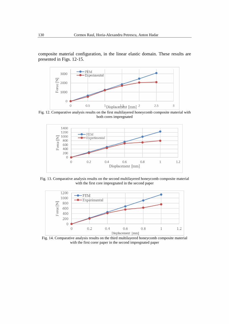
Fig. 13. Comparative analysis results on the second multilayered honeycomb composite material
with the first core impregnated in the second paper
Fig. 14. Comparative analysis results on the third multilayered honeycomb composite material
with the first corer paper in the second impregnated paper
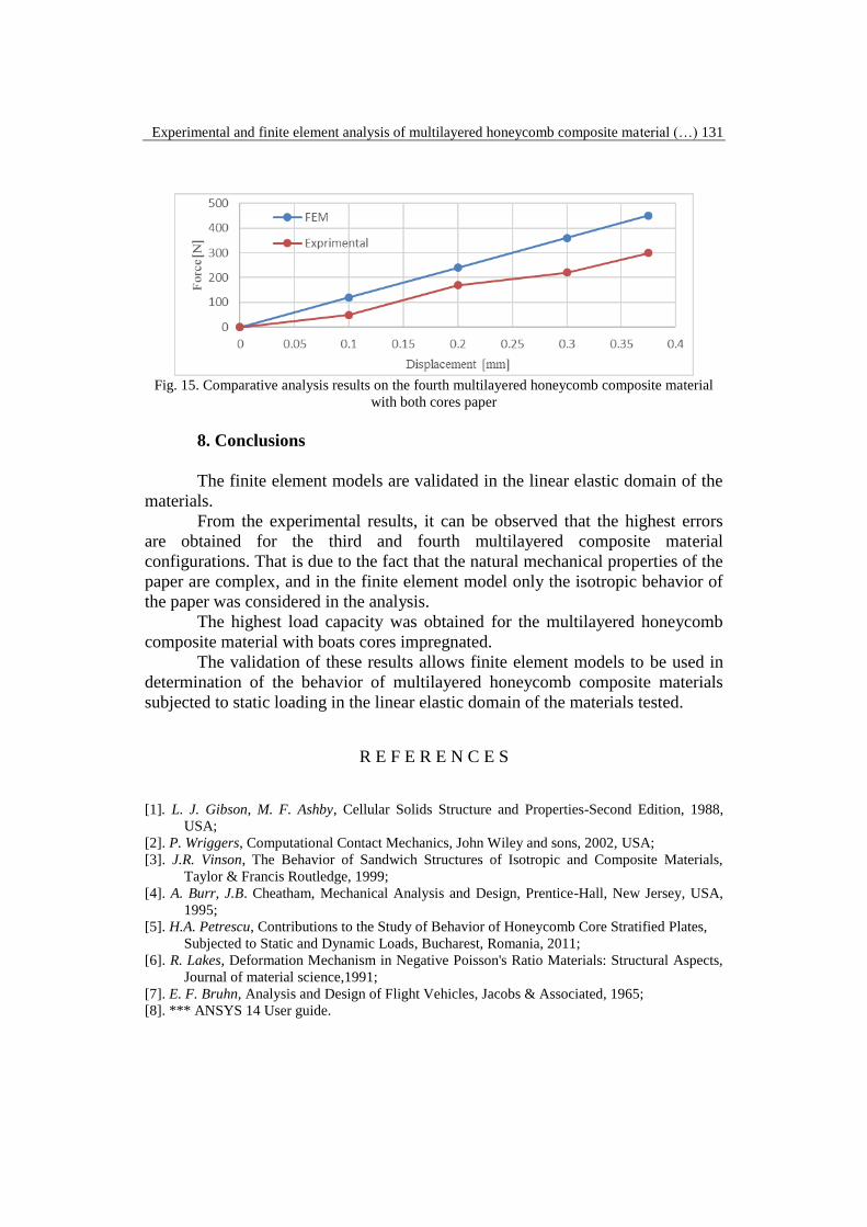
Experimental and finite element analysis of multilayered honeycomb composite material (…) 131
Fig. 15. Comparative analysis results on the fourth multilayered honeycomb composite material
with both cores paper
8. Conclusions
The finite element models are validated in the linear elastic domain of the
materials.
From the experimental results, it can be observed that the highest errors
are obtained for the third and fourth multilayered composite material
configurations. That is due to the fact that the natural mechanical properties of the
paper are complex, and in the finite element model only the isotropic behavior of
the paper was considered in the analysis.
The highest load capacity was obtained for the multilayered honeycomb
composite material with boats cores impregnated.
The validation of these results allows finite element models to be used in
determination of the behavior of multilayered honeycomb composite materials
subjected to static loading in the linear elastic domain of the materials tested.
R E F E R E N C E S
[1]. L. J. Gibson, M. F. Ashby, Cellular Solids Structure and Properties-Second Edition, 1988,
USA;
[2]. P. Wriggers, Computational Contact Mechanics, John Wiley and sons, 2002, USA;
[3]. J.R. Vinson, The Behavior of Sandwich Structures of Isotropic and Composite Materials,
Taylor & Francis Routledge, 1999;
[4]. A. Burr, J.B. Cheatham, Mechanical Analysis and Design, Prentice-Hall, New Jersey, USA,
1995;
[5]. H.A. Petrescu, Contributions to the Study of Behavior of Honeycomb Core Stratified Plates,
Subjected to Static and Dynamic Loads, Bucharest, Romania, 2011;
[6]. R. Lakes, Deformation Mechanism in Negative Poisson's Ratio Materials: Structural Aspects,
Journal of material science,1991;
[7]. E. F. Bruhn, Analysis and Design of Flight Vehicles, Jacobs & Associated, 1965;
[8]. *** ANSYS 14 User guide.
132 Cormos Raul, Horia-Alexandru Petrescu, Anton Hadar
[9]. S.A. Galehdaria, M. Kadkhodayana, S. Hadidi-Mouda, Analytical, Experimental and
Numerical Study of Agraded Honeycomb Structure under In-Plane Impact Load with Low
Velocity, International Journal of Crashworthiness Vol. 20, Iss. 4, 2015, pp. 387-400
[10]. C. Kassapoglou, Stress Determination and Core Failure Analysis in Sandwich Rampdown
Structures under Bending Loads, Key Engineering Materials 120-121 pp. 307-328, January
1996
[11]. T. Zhu, J. Chen, W. Gong, Numerical Analysis of Debonded Honeycomb Sandwich Structure
under Compressive Load, Advanced Materials Research, Vol 658, pp 227-231, Trans Tech
Publications, Switzerland, 2013
[12]. M. Xihuia, M. Xiaoyub, Z. Xiaoyac, Numerical Computation for Effective Mechanical
Properties of Honeycomb Core Structure, Advanced Materials Research, Vol. 912-914, pp
460-465, Trans Tech Publications, Switzerland, 2014
[13]. A. Akatay, M.O. Bora, O. Coban, S. Fidan, V. Tuna, The influence of low velocity repeated
impacts on residual compressive properties of honeycomb sandwich structures, Compos.
Struct. 125 (2015), pp. 425-433.
[14]. W. Abramowicz, Thin-walled structures as impact energy absorbers, Thin Wall. Struct. 41
(2003), pp. 91-107.
[15]. N.K. Gupta, G.L. Easwara Prasad, S.K. Gupta, Plastic collapse of metallic conical frusta of
large semi-apical angles, Int. J. Crashworthiness 2 (1997), pp. 349-366.
[16]. A. Meran, C. Baykasoglu, A. Mugan, T. Toprak, Development of a Design for a Crash
Energy Management System for Use in a Railway Passenger Car, Proc. Inst. Mech. Eng. F
J. Rail Rapid Transit. 230, 2016, pp. 206-219.
[17]. C.C. Foo, G.B. Chai, L.K. Seah, Mechanical properties of Nomex material and Nomex
honeycomb structure, Composite Structures, vol. 80, Elsevier, 2007, pp. 588–594.


