Embed Size (px)
Citation preview

R. T. FRANKIAN & ASSOCIATES 1329 scott road burbank california 91504
tel. (818) 531-1501 fax (818) 531-1511 www.rtfrankian.com
May 23, 2014 Chiquita Canyon Landfill 29201 Henry Mayo Drive Castaic, California 91384 Job No. 2002-036-004 Attention: Mr. Michael Dean Division Vice President Subject: Geotechnical Evaluation of Updated Excavation Plan
Master Plan Revision Chiquita Canyon Landfill 29201 Henry Mayo Drive Castaic, California
Gentlemen:
This letter summarizes the findings from R. T. Frankian & Associates’ (RTF&A)
geotechnical evaluation of the updated Chiquita Canyon Landfill (CCL) Proposed Project
Excavation Plan (herein referred to as the 2014 Excavation Plan) for the Master Plan Revision
(MPR). The 2014 Excavation Plan, prepared by Golder Associates (Golder) and dated April 30,
2014, supersedes the December 2011 Golder Excavation Plan presented in our January 27, 2012
MPR geotechnical investigation report (RTF&A, 2012c).
Since the completion of our 2012 MPR report, RTF&A has provided additional
geotechnical services for CCL. These have included construction observation services during
development of Cell 5 (RTF&A, 2012d and 2012e) and a geotechnical investigation for future
Cell 6 (RTF&A, 2014). Geologic and geotechnical data developed for this additional work have
been incorporated into this geotechnical evaluation.

Chiquita Canyon Landfill May 23, 2014 2002-036-004 Page 2
SUMMARY OF 2014 EXCAVATION PLAN REVISIONS
The 2014 Excavation Plan revisions are primarily associated with the future landfill
entrance facility and the Future Potential Conversion Technology Set-Aside Area (herein
referred to as the “Set-Aside Area”). The landfill entrance facility will be located in the
southwest corner of the CCL site, northwest of the intersection of California State Highway 126
(also known as Henry Mayo Drive in the vicinity of CCL) and Wolcott Way. It will include a
new entrance road, scales, gatehouse, and administration building. The new entrance road
alignment will extend westerly from the current intersection of Franklin Parkway and Wolcott
Way, extending west-southwesterly toward the current landfill entrance. The 2011 Excavation
Plan indicated the grading of two cut slopes at the west end of the entrance facility. Revisions to
the entrance facility, as depicted on the 2014 Excavation Plan, indicate two additional cut slopes,
and modification of one of the previously proposed cut slopes.
The Set-Aside Area will be located within a southerly-draining steep-walled canyon
(herein referred to as “Wolcott Canyon”) located immediately north of the intersection of
Wolcott Way and Franklin Parkway. Potential grading for the Set-Aside Area will include
construction of a near-level pad at approximate elevation 1025 feet above mean sea level (msl),
with associated cut and fill slopes surrounding the pad. The Set-Aside Area pad will be
accessible by way of road extending from the north end of Wolcott Way to the southwest corner
of the graded pad.
The 2011 Excavation Plan indicated Potential Borrow Area cut slopes along the northern
and northwestern walls of Wolcott Canyon. The 2014 Excavation Plan includes an additional
Potential Borrow Area cut slope and pad southwest of the Set-Aside Area pad.
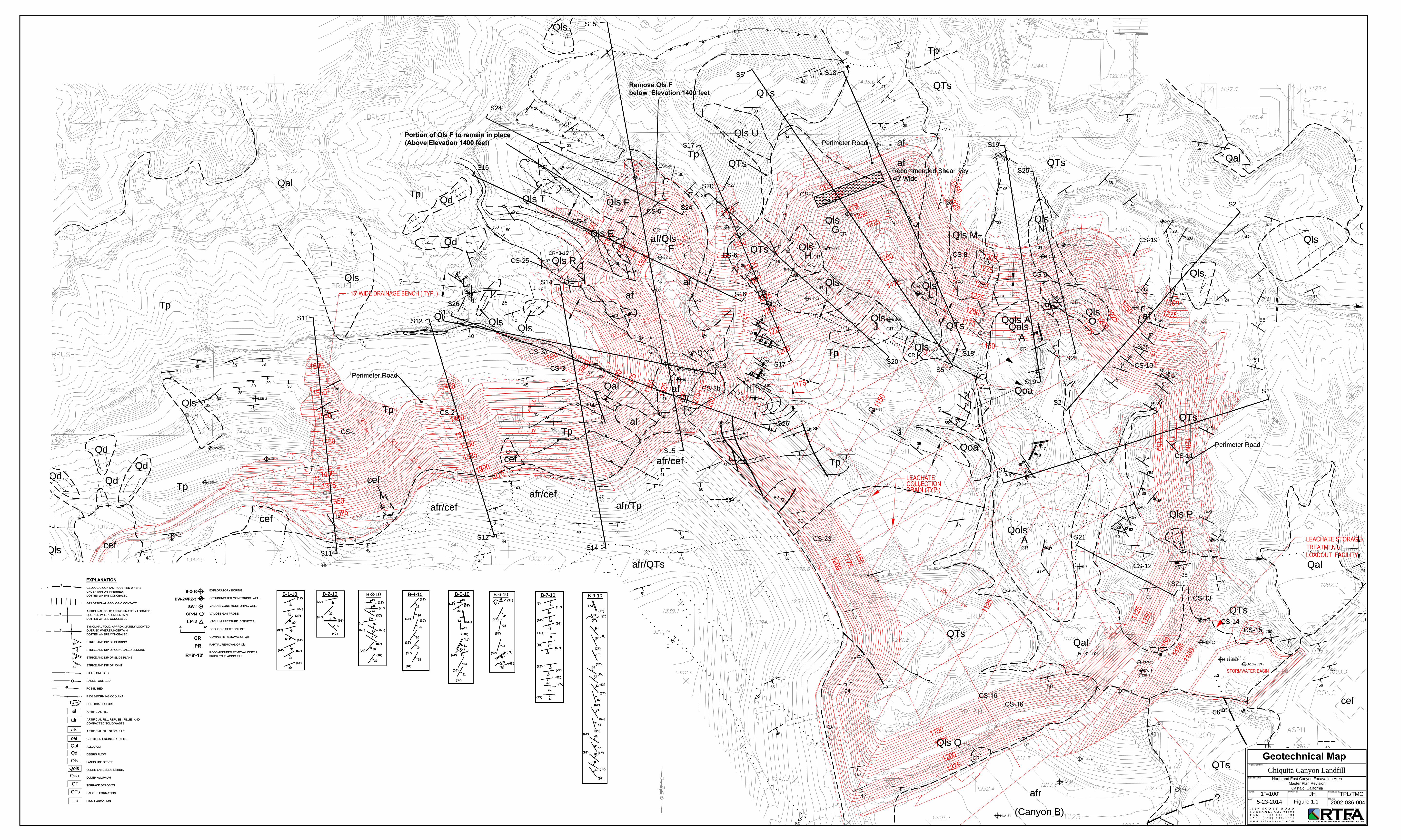
The grading associated with the 2014 Excavation Plan is indicated on our Geotechnical
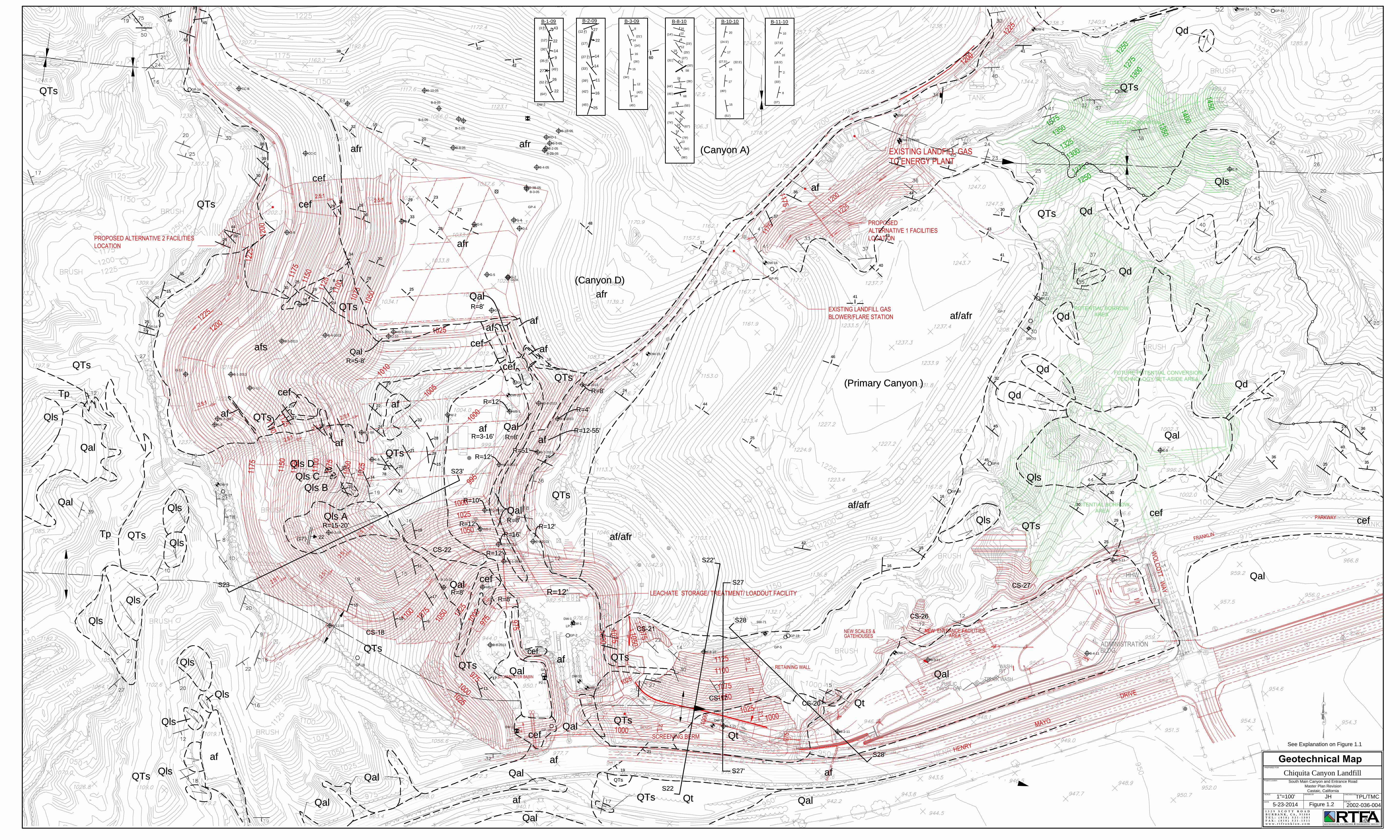
Map, presented as Figures 1.1 and 1.2. The 2014 Excavation Plan is included as Figure 2.

Chiquita Canyon Landfill May 23, 2014 2002-036-004 Page 3
GEOTECHNICAL EVALUATION
The geotechnical evaluation was performed to provide additional temporary slope
stability calculations for Cut Slope CS-7 and to assess the impact of the site geologic and
geotechnical conditions relative to the revised MPR development at CCL, as depicted on the
2014 Excavation Plan. This included RTF&A evaluating the stability of proposed new cut
slopes. The geologic conditions within the site are shown on the Geotechnical Map (Figures 1.1
and 1.2). The geologic data presented in our 2012 MPR report (RTF&A, 2012c) have been
slightly modified to reflect new findings from studies post-dating our 2012 report, changed
geologic interpretations, and/or corrections. Specifically, we have revised the depiction of the
inactive faulting identified in East Canyon, based on our 2006 fault study (RTF&A, 2006b) and
adjusted geologic contacts in the areas of Cell 5 and future Cell 6, based on additional
geotechnical work (RTF&A, 2012d, 2012e, and 2014). The adjusted geologic contacts were
mapped using the March 12, 2013 aerial survey prepared by Cooper Aerial Survey Co.
From a geotechnical standpoint, the most significant plan revisions relate to the grading
proposed along the north side of the landfill entrance facility in which two new cut slopes
(designated as Cut Slopes CS-26 and CS-27) are proposed, and a previously planned cut slope
(Cut Slope CS-20) will be relocated and reduced in height. The three cut slopes are indicated on
the Geotechnical Map (Figure 1.2). Data specific to the three cut slopes, including slope height,
gradient, and underlying geologic conditions, are summarized in Table 1, Summary of Cut
Slopes. The stability of the three cut slopes is addressed below. Additionally, we are providing
a preliminary evaluation of the potential grading of the Set-Aside Area and Potential Borrow
Area slopes.
We also received feedback from Los Angeles County Department of Public Works
Geotechnical Materials and Engineering Division (GMED) relative to factor of safety
requirements for the proposed temporary excavation slopes that have the potential to exist for an
extended period of time. GMED indicated that a temporary factor of safety of 1.25 is acceptable
for the proposed excavation slopes within the Chiquita Canyon Landfill property boundary.

Chiquita Canyon Landfill May 23, 2014 2002-036-004 Page 4
However, any potential failure planes that daylight off property that have the potential to exist in
an unmodified condition for an extended period of time will need to meet the GMED static factor
of safety requirements of 1.5 for permanent slopes.
We have reviewed the numerous proposed cut slopes for the 2012 MPR Report and have
determined that only proposed Cut Slope CS-7, depicted on Geotechnical Section S5-S5’ (Figure
3 of this report), has the potential to exist unmodified for an extended period of time and has a
failure plane that extends off-site that will have a factor of safety of less than 1.5. In addition to
the revised geotechnical evaluation for plan revisions presented in this report, we also performed
additional slope stability calculations for Cut Slope CS-7 as presented below. Table 1 from our
MPR Report has been updated based on the slope stability evaluations and is re-presented in this
report.
CUT SLOPE CS-7
Cut Slope CS-7 (Figure 1.1) will be graded as a southeast- to southwest-facing, 2:1 to 3:1
slope. The total slope height is approximately 205 feet high, with the upper (permanent) portion
of the cut slope approximately 35 feet high and the lower (lined) portion of the slope 170 feet
high. The cut slope will encounter Saugus Formation units and landslides Qls G through Qls I,
and Qls L. Bedding in the underlying Saugus Formation strikes from north-south to northeast,
with easterly dips between 20 and 40 degrees. As indicated on Geotechnical Section S5-S5’
(Figure 3), a daylighted bedding component of 17 degrees will be exposed in the cut slope
(RTF&A, 2012c). It is anticipated that grading of Cut Slope CS-7 will remove landslides Qls G
through Qls I, and Qls L. If any landslide debris remains after completion of the cut slope, the
debris should be removed and certified engineered fill placed to restore grade.
Cut Slope CS-7 has the potential to exist for an extended period of time and has a
potential bedding plane that extends beyond the Chiquita Canyon Landfill property limit.
Accordingly, a static factor of safety of 1.5 will be required. As presented in the MRP report
(RTF&A, 2012c), the static factor of safety is greater than 1.25, but is less than 1.5. Slope

Chiquita Canyon Landfill May 23, 2014 2002-036-004 Page 5
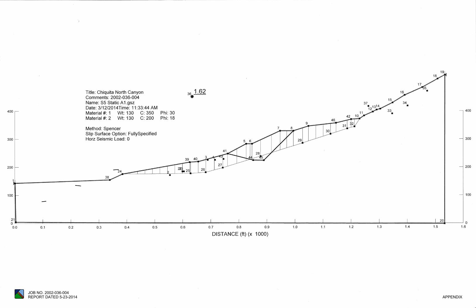
stability calculations were performed for a buttress shear key design that meets the GMED slope
stability static factor of safety requirements of 1.5. The slope stability calculations were
performed using the below listed shear strength parameters and the computer program Slope/W.
The slope stability calculations are presented in the Appendix of this report. The proposed
buttress shear key and the slope stability results that exceed a static factor of safety of 1.5 are
shown on Geotechnical Section S5-S5’.
The recommended shear strength parameters are based on the results of the direct shear
test results (RTF&A, 2012c). In addition, we also reviewed shear strength parameters presented
in the referenced report for the subject site and nearby vicinity. Presented in the following table
are the selected bedding plane shear strengths, as well as the cross-bedding and compacted fill
shear strengths recommended for slope stability evaluation at the site.
MATERIAL
COHESION (psf)
ANGLE OF SHEARING RESISTANCE (degrees)
Landslide Failure Plane (MSR) 100 10 QTs & Tp Bedding Plane (MSR) 200 18 Seismic Bedding Plane (SSR) 300 26 QTs Cross Bedding (SSR) 600 36 Tp Cross Bedding (SSR) 500 30 Compacted Fill (SSR) 350 30
Mitigation to obtain a permanent factor of safety of 1.5 for Cut Slope CS-7 will consist of
excavating a 40-foot-wide buttress shear key at approximate elevation of 1,300 feet,
downgradient from the proposed perimeter road, as depicted on Figure 1.1 and attached
Geotechnical Section S5-S5’. Construction of the recommended buttress shear key provides the
required factor of safety of 1.5 for static slope stability conditions, as presented in Figure 3 and
the Appendix.
CUT SLOPE CS-20
Cut Slope CS-20 will be graded as a southeast-facing, 2:1 (horizontal:vertical) slope, to a
height of approximately 30 feet. The cut slope will be graded for a debris basin along the north

Chiquita Canyon Landfill May 23, 2014 2002-036-004 Page 6
side of the project. The upper portion of the cut slope will expose Saugus Formation units;
Pleistocene terrace deposits could be encountered in the lower portion of CS-20. Bedding in the
Saugus Formation strikes northwest and dips 15 degrees to the northeast, with an apparent
bedding of 6 degrees dipping into the proposed cut slope. The Saugus Formation bedding
orientation is favorable with respect to the southeast-facing cut slope. Bedding within the terrace
deposits is essentially flat-lying and is grossly stable. Accordingly, Cut Slope CS-20 is
considered grossly stable from a geologic standpoint.
CUT SLOPE CS-26
Cut Slope CS-26 is proposed as an 85-foot-high, southwest-facing, 2:1 slope. The cut
slope will expose Saugus Formation units in which the underlying bedding strikes northwest and
dips 12 degrees towards the northeast. This bedding orientation is favorable with respect to
southwest-facing cut slope, and Cut Slope CS-26 is considered grossly stable from a geologic
standpoint.
CUT SLOPE CS-27
Cut Slope CS-27 will consist of a 75-foot-high, south- to southwest-facing, 2:1 slope.
The cut slope is underlain by Saugus Formation units in which the bedding strikes northwest,
dipping 15 to 25 degrees towards the northeast. This bedding orientation is favorable with
respect to Cut Slope CS-27, and the cut slope is considered grossly stable from a geologic
standpoint.
POTENTIAL SET-ASIDE AREA AND BORROW AREA SLOPES
The 2014 Excavation Plan includes grading for potential improvements in the Set-Aside
Area and three Potential Borrow Areas, as depicted with green elevation contours on Figure 1.2.
As shown on Figure 1.2, perimeter cut slopes would be created for any grading associated with
the Set-Aside Area pad, including slopes on the north and east sides of the pad, as well as a

Chiquita Canyon Landfill May 23, 2014 2002-036-004 Page 7
borrow area slope along the northwest side. These slopes would range from 100 feet on the
north and east to approximately 125 feet for the northwest borrow area slope. The proposed pad
elevation of the Set-Aside Area would be established at an elevation of approximately 1025 feet
msl. Additionally, borrow area slopes would be graded along the western and northern walls of
Wolcott Canyon. The maximum proposed heights for these slopes range from 100 feet to 225
feet.
The cut slopes will encounter sedimentary bedrock units of the Saugus Formation, with
the underlying bedding striking northwest and dipping approximately 20 to 40 degrees towards
the northeast. Based on the orientation of bedding relative to cut slopes, there is a potential for
adversely dipping, or “daylighted,” bedding for the easterly-facing cut slopes along the western
side of Wolcott Canyon. Potential daylighted bedding may require some type of stabilization,
such as buttresses, retaining walls, or flattening of the cut slope gradient.
Landslides would likely be encountered in the 160-foot-high borrow area cut slope in the
southwest corner of the Set-Aside Area, and in the borrow area cut slope along the north wall of
Wolcott Canyon. Both landslides would require complete removal to establish a stable slope
configuration if the potential grading depicted on the 2014 Excavation Plan is implemented. If
the cut slopes do not effectively remove the landslides, additional excavation deeper than the
proposed cut grades would be necessary to remove the slide debris, and the slope grades restored
with engineered fill.
The floor of the Set-Aside Area is mantled by Holocene alluvial deposits. These
materials may be susceptible to liquefaction and/or hydroconsolidation. If grading of the Set-
Aside Area is performed, alluvial deposits determined to be susceptible to liquefaction or
hydroconsolidation would need to be removed and replaced with engineered fill materials.
Once site-specific grading plans are developed for the Set-Aside Area and the Potential
Borrow Area slopes, geotechnical investigations will need to be performed to refine the
geotechnical mitigation measures and recommendations addressed above.

Chiquita Canyon Landfill May 23, 2014 2002-036-004 Page 8
SECTION 111 STATEMENT
Based on our review of the 2014 Excavation Plan and the referenced reports, it is our
professional opinion that the proposed MPR development will be safe from hazard of landslide,
settlement, or slippage and will not adversely affect the geotechnical conditions of off-site
properties, provided our recommendations and the requirements of the Los Angeles County
Building Code are followed.
Our professional services have been performed using that degree of care and skill
ordinarily exercised, under similar circumstances, by reputable geotechnical engineers and
geologists practicing in this or similar localities. No other warranty, expressed or implied, is
made as to the professional advice included in this report. This report has been prepared for CCL
and their design consultants, to be used solely for planning and design of the MPR and associated
grading.


Chiquita Canyon Landfill May 23, 2014 2002-036-004
REFERENCES
EMCON, 1990a, “Geologic/Hydrogeologic Report, Chiquita Canyon Landfill Expansion, Los
Angeles County, California,” for Laidlaw Waste Systems, dated May 1990 (sic), Project No. 976-03.04.
EMCON, 1990b, “Fault Investigation, Chiquita Canyon Landfill, Los Angeles County,
California,” for Laidlaw Waste Systems, dated October 19, 1990, Project No. 976-03.13. EMCON, 1997a, “Joint Technical Document, Chiquita Canyon Landfill,” for Chiquita Canyon
Landfill, Inc., dated September 1997, Project No. 976-003.026. EMCON, 1997b, “Chiquita Canyon Landfill Cell Development, Canyon C., Cell II, Phase 2a
Subgrade Geologic Mapping,” prepared for California Regional Water Quality Control Board, Los Angeles Region, dated September 21, 1997.
EMCON, 1997c, “Chiquita Canyon Landfill Cell Development; Canyon C, Cell II, Phase 2B
Subgrade Geologic Mapping,” for USA Waste Services, dated October 21, 1997, Project No. 20976-001.048.
Frankian, R. T., & Associates, 1989, “Report of Geotechnical Investigation, Tentative Tract No. 19784, Hasley Industrial Center, Valencia, California,” for Valencia Company, dated August 11, 1989, Job No. 88-059-FT.
Frankian, R. T., & Associates, 1990, “Report of Geotechnical Investigations, Proposed U. S. Post
Office Site and Vicinity, Valencia, California,” dated February 2, 1990, Job No. 85-183-F3.
Frankian, R. T., & Associates, 1992, “Report of Geotechnical Investigation, Post Office Site and
Vicinity, Franklin Parkway Extension to Route 126, Valencia, California,” dated September 28, 1992, Job No. 89-025-F7.
Frankian, R. T., & Associates, 2003, “Geotechnical Report of Observation and Testing And As-
Built Geologic Report, Sedimentation Basin, Chiquita Canyon Landfill, Valencia, California,” for Chiquita Canyon Landfill, Republic Services, Inc., dated April 4, 2003, Job No. 2002-033-11.
Frankian, R. T., & Associates, 2005, “Semi-Annual Groundwater Monitoring Report, First and
Second Quarters 2005, Chiquita Canyon Landfill Compliance File No. C1-6231, Valencia, California,” for Chiquita Canyon Landfill, dated June 29, 2005, Job No. 2004-001-90.
Chiquita Canyon Landfill May 23, 2014 2002-036-004 References Page 2
Frankian, R. T., & Associates, 2006a, “Slope Stability Study, East Main Canyon, Chiquita
Canyon Landfill, Valencia, California,” for Chiquita Canyon Landfill, dated March 13, 2006, Job No. 2002-036-01.
Frankian, R. T., & Associates, 2006b, “Geologic Fault Study, East Canyon, Chiquita Canyon
Landfill, Valencia, California,” for Chiquita Canyon Landfill, dated April 11, 2006, Job No. 2002-036-01.
Frankian, R. T., & Associates, 2009a, “Semi-Annual Groundwater Monitoring Report, First and
Second Quarters 2009, Chiquita Canyon Landfill Compliance File No. C1-6231, Valencia, California,” for Chiquita Canyon Landfill, dated June 29, 2009, Job No. 2004-001-90.
Frankian, R. T., & Associates, 2009b, “Geotechnical Investigation, South Main Canyon,
Chiquita Canyon Landfill, Castaic, California,” for Chiquita Canyon Landfill, dated November 20, 2009, Job No. 2002-036-03.
Frankian, R. T., & Associates, 2012a, “Geotechnical Investigation, Landfill Entrance Road,
Chiquita Canyon Landfill, 29201 Henry Mayo Drive, Castaic, California,” for Chiquita Canyon Landfill, dated January 13, 2012, Job No. 2002-036-006.
Frankian, R. T., & Associates, 2012b, Hydrogeologic Report, Chiquita Canyon Landfill, Castaic,
California,” for Chiquita Canyon Landfill, dated January 20, 2012, Job No. 2002-036-005.
Frankian, R. T., & Associates, 2012c, “Geotechnical Investigation, Master Plan Revision,
Chiquita Canyon Landfill, Castaic, California,” for Chiquita Canyon Landfill, dated January 27, 2012, Job No. 2002-036-004.
Frankian, R. T., & Associates, 2012d, “Report of Geotechnical and Geosynthetic CQA Services,
Chiquita Canyon Landfill, Cell 5 Expansion, File No. 67-020, Wdid No. 4A190359001, 29201 Henry Mayo Drive, Castaic, California,” for Chiquita Canyon Landfill, dated September 21, 2012, Job No. 2002-036-008.
Frankian, R. T., & Associates, 2012e, “Report of Geotechnical Observation and Testing Services, Grading and Construction Activities, Areas Beyond Constructed Cell 5 Liner Limits, Chiquita Canyon Landfill, Castaic, California,” for Chiquita Canyon Landfill, dated November 30, 2012, Job No. 2002-036-004.

Chiquita Canyon Landfill May 23, 2014 2002-036-004 References Page 3
Frankian, R. T., & Associates, 2014, “Geotechnical Investigation, Cell 6 Design Report, Chiquita Canyon Landfill, Castaic, California,” for Chiquita Canyon Landfill, dated February 25, 2014, Job No. 2002-036-004.
GeoLogic Associates, 2005a, “Exploratory Geotechnical Report, Module 3/4/5 Liner Design and
Construction, Chiquita Canyon Landfill, Valencia, California,” for Bryan A. Stirrat & Associates, dated January 28, 2005, Job No. 2004-207.
GeoLogic Associates, 2005b, “Exploratory Geotechnical Report Addendum, Module 3/4/5 Liner
Design and Construction, Chiquita Canyon Landfill, Valencia, California,” for Bryan A. Stirrat & Associates, dated February 14, 2005, Job No. 2004-207.
GeoLogic Associates, 2005c, “Composite Liner System Construction, Report of Geotechnical
and Geosynthetic CQA Services, Cells 4 and 5, Chiquita Canyon Landfill, Valencia, California,” for Republic Services of California, LLC, dated December 2005, Job No. 2005-071.
Shaw-EMCON/OWT, 2002, “Report on Evaluation of Existing Landslide Area, Chiquita
Canyon Landfill, Los Angeles County, California,” for Republic Services of California, dated December 2002, Project 827026, Task 40000000.
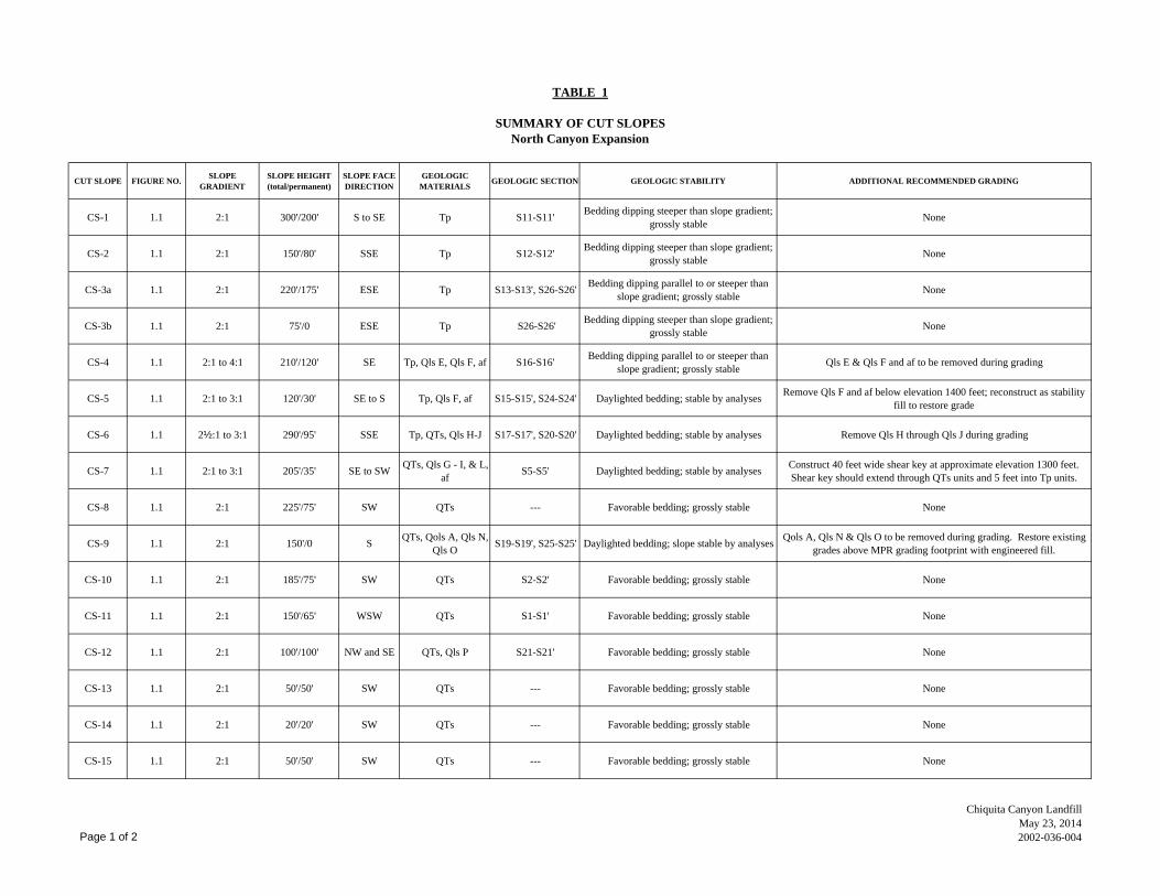
TABLE 1
SUMMARY OF CUT SLOPESNorth Canyon Expansion
CUT SLOPE FIGURE NO. SLOPE GRADIENT
SLOPE HEIGHT (total/permanent)
SLOPE FACE DIRECTION
GEOLOGIC MATERIALS GEOLOGIC SECTION GEOLOGIC STABILITY ADDITIONAL RECOMMENDED GRADING
CS-1 1.1 2:1 300'/200' S to SE Tp S11-S11' Bedding dipping steeper than slope gradient; grossly stable None
CS-2 1.1 2:1 150'/80' SSE Tp S12-S12' Bedding dipping steeper than slope gradient; grossly stable None
CS-3a 1.1 2:1 220'/175' ESE Tp S13-S13', S26-S26' Bedding dipping parallel to or steeper than slope gradient; grossly stable None
CS-3b 1.1 2:1 75'/0 ESE Tp S26-S26' Bedding dipping steeper than slope gradient; grossly stable None
CS-4 1.1 2:1 to 4:1 210'/120' SE Tp, Qls E, Qls F, af S16-S16' Bedding dipping parallel to or steeper than slope gradient; grossly stable Qls E & Qls F and af to be removed during grading
CS-5 1.1 2:1 to 3:1 120'/30' SE to S Tp, Qls F, af S15-S15', S24-S24' Daylighted bedding; stable by analyses Remove Qls F and af below elevation 1400 feet; reconstruct as stability fill to restore grade
CS-6 1.1 2½:1 to 3:1 290'/95' SSE Tp, QTs, Qls H-J S17-S17', S20-S20' Daylighted bedding; stable by analyses Remove Qls H through Qls J during grading
CS-7 1.1 2:1 to 3:1 205'/35' SE to SW QTs, Qls G - I, & L, af S5-S5' Daylighted bedding; stable by analyses Construct 40 feet wide shear key at approximate elevation 1300 feet.
Shear key should extend through QTs units and 5 feet into Tp units.
CS-8 1.1 2:1 225'/75' SW QTs --- Favorable bedding; grossly stable None
CS-9 1.1 2:1 150'/0 S QTs, Qols A, Qls N, Qls O S19-S19', S25-S25' Daylighted bedding; slope stable by analyses Qols A, Qls N & Qls O to be removed during grading. Restore existing
grades above MPR grading footprint with engineered fill.
CS-10 1.1 2:1 185'/75' SW QTs S2-S2' Favorable bedding; grossly stable None
CS-11 1.1 2:1 150'/65' WSW QTs S1-S1' Favorable bedding; grossly stable None
CS-12 1.1 2:1 100'/100' NW and SE QTs, Qls P S21-S21' Favorable bedding; grossly stable None
CS-13 1.1 2:1 50'/50' SW QTs --- Favorable bedding; grossly stable None
CS-14 1.1 2:1 20'/20' SW QTs --- Favorable bedding; grossly stable None
CS-15 1.1 2:1 50'/50' SW QTs --- Favorable bedding; grossly stable None
Page 1 of 2
Chiquita Canyon LandfillMay 23, 20142002-036-004

TABLE 1
SUMMARY OF CUT SLOPESNorth Canyon Expansion
CUT SLOPE FIGURE NO. SLOPE GRADIENT
SLOPE HEIGHT (total/permanent)
SLOPE FACE DIRECTION
GEOLOGIC MATERIALS GEOLOGIC SECTION GEOLOGIC STABILITY ADDITIONAL RECOMMENDED GRADING
CS-16 1.1 2:1 110'/0 NW QTs --- Favorable bedding; grossly stable None
CS-17 1.2 2:1 160'/160' S QTs, Qt S22-S22', S27-S27' Favorable bedding; grossly stable Construct stability fill slopes above and below entrance to control erosion
CS-18 1.2 2:1 200'/200' E QTs, Qls A S23-S23' Daylighted bedding; stable by analyses Qls A to be removed during grading; if needed place engineered fill to restore slope grades
CS-19 1.1 2:1 50'/50' WSW QTs --- Favorable bedding; grossly stable None
CS-20 1.2 2:1 30'/30' SE QTs, Qt --- Favorable bedding; grossly stable None
CS-21 1.2 2:1 85'/85' W QTs --- Favorable bedding; grossly stable None
CS-22 1.2 2:1 100'/100' SSE QTs --- Favorable bedding; grossly stable None
CS-23 1.1 2:1 85'/0 ENE to E Tp, QTs --- Favorable bedding; grossly stable None
CS-24 1.2 2-1/2:1 235'/60' E to N QTs, afs --- Bedding dipping steeper than slope gradient; grossly stable Remove "afs" and reconstruct as engineered fill slope
CS-25 1.1 2:1 35'/35' SE Tp --- Bedding dipping steeper than slope gradient; grossly stable None
CS-26 1.2 2:1 85'/85' SW QTs --- Favorable bedding; grossly stable None
CS-27 1.2 2:1 75'/75' SW QTs --- Favorable bedding; grossly stable None
Page 2 of 2
Chiquita Canyon LandfillMay 23, 20142002-036-004
1500
1550
1600
1450
1350
13751400
1325
1375
1400
1450
12751300
1350
1325
1500
1450
137514
00
130013
5013
25
1275
1400
1250
1300
1350
1400
1375
1350
1300
1200
13251300
12751250
1225
13251350
1300
12501225
1275
12001175
1175
1200
1150
1275
12501225120011751300
1175
1200
1150
1125
117511501200
1250 1150
1325
1225
1275
1325
1175
MAIN CANYONLANDFILL
3%
2:1
3:1
2:12:1
2:1
2:1
2:1
2:1
2:1
2:1
STORMWATER BASIN
3:1
3:1
3:12:1
2:12:1
2:1
2:1
2:1
2:1
2:1
2:1
LEACHATE STORAGE/TREATMENT/LOADOUT FACILITY
15'-WIDE DRAINAGE BENCH ( TYP. )
2.5:1
2:1
2:1
2.5:12.5:1
2:1
Qls
Tp
Qls
QlsQls
Qls
QTs
Tp
Tp
Qols
QTs
QTs
Qal
afr
Qls F
QdQd
afr/Tp
Tp
Tp
Tp
QTs
22
12
23
41
50
17
52
45
Qal
cef
?
Qls
45
4449
61
85
?
?
QTs
Qls Q
38
23
45
47
5452
23
24
74
58
56
70
56
60
80
90
58
63
65
56
(Canyon B)
(Canyon C)
afr/QTs
afr/cef
Qal
?
65
45
56
24
62
61
52
QTs
cef
cef
Qal
Qoa
Qoa74
7555
35
83
54
54
27
40
74
60
45
36
41
47
48
Qls U
33
Qls
Qls af
18
24
45
57
55
47
54 52
52
60
55
45
27
40
53
30
10
23
29
31
27
15
13
30
16
38
44
76
60
7447
72
74
60
49
20
24
15
83
Qls Qls
Qd
Qd
90af
af
Qal
90
af47
Qls R
Qls
58
40
4073
27
82
53
**
*
* *
*
*
X
X
X
X
XX
XX
X
X
XX
X
X
X
X
41
28
33
29
13
64
54
Qd
Qls M
?
*
47
8
46
0-1043
48
79
26
82
50
Qls
48
42
61
58
Qls T
27
X
X
X
X
XX
27
39
37
30
**
***
*
*
36
**
*
*
**
13
Qls P
Qols A
?
?
QTs
QTs
XXX
X
X
**
X
X
X
X
X
X
X
X
X
X
X
XX
X
* *
afr/cef
Tp
75
48
af/Qls
31
37
af
30
80
7532
63
75
6874
|||||||||||||||||||
|||||||||
90
Qd
Qls
51afr/QTs
afr/cefQd
cef
afr/cef
45
42
36
5340
36
48
40
30
35
40
42
47
48
40
50
78
4242
60
38
55
52
40
38
68
40
57
26
2930
28
Tp
Qal
65
42
cef
afr/cef
afr/Tp
(Main Canyon)
CS-1
CS-2
CS-3
CS-4CS-5
CS-6
CS-7
af
CS-8
CS-9
CS-19
CS-10
CS-11
CS-12
41
46
3743
36
47
49
2537
30
27 2926
21
2533
Qls E G
H
I
J
K
L
N
O
*****
* **
** *
**
**
*
**
* * * * * * * ** * * *
* * * * * *Qls
28Tp
QTs
34
57
61
59
71
39
CS-14
5239
||||||||||||
45
44
6546
72
49
44
42
38
44
52
48
43
42
56
51
55
50
50
41
39
afr/Tp47
48 50
afr/cef43
47
44
43
43
47
43 55
58
53
40
43
48
44
48
49
52
?
?
?
?
Qt
Qls
72
42
57
51
afr/QTs
A
CR=8-15'
Approximate Location of25 feet Wide Keyway
CS-3
CS-4CS-5
CS-6
CS-7
CS-3
CS-4CS-5
CS-6
CS-7
QTs
CR
|||||||||||||||||||
|||||||||
S11'
S11
S12
S12'
S14
S13
S13'
S14'
S15'
S16'
S16
S17
S17'
S5
S5'
S18'
S18'
S19
S19'
S2
S2'
S1
S1'
41
46
3743
36
H
I
J
K
L
N
A
O
S20'
S20
S21
S21'
||||||||||||
S25
A
S26
S26'
Portion of Qls F to remain in place
(Above Elevation 1400 feet)
Perimeter Road
Perimeter Road
Perimeter Road
Recommended Shear Key40' Wide
B-11-2013B-10-2013
B-1-03
B-2-03
B-3-03
B-4-03
B-5-03
B-6-03
B-7-03
B-8-03
CC-A
DW-19
DW-23
DW-24DW-25
DW-26
DW-27
DW-28
DW-3
DW-8
E-6
E-7
GP-10/VP-1
GP-11
GP-12
GP-13
GP-15
GP-24
GP-25
GP-3
GP-8
GP-9
GP-A
GP-B
HLA-B1
HLA-B2
HLA-B3
HLA-B4
PZ-3
PZ-4
PZ-5
PZ-6
PZ-7
SW-32
E-2
E-1
LSB-4
LSB-3
LSB-2
LSB-1
HS-1-10
HS-4-10
HS-3-10
HS-2-10
B-1-10
B-2-10
B-3-10
B-4-10
B-5-10
B-6-10
B-7-10
B-9-10PZ-8
GP-26
Qls
Tp
Qls
QlsQls
Qls
QTs
Tp
Tp
Qols
QTs
QTs
Qal
afr
Qls F
QdQd
afr/Tp
Tp
Tp
Tp
QTs
22
12
23
41
50
17
52
45
Qal
cef
?
Qls
45
4449
61
85
?
?
QTs
Qls Q
38
23
45
47
5452
23
24
74
58
56
70
56
60
80
90
58
63
65
56
(Canyon B)
(Canyon C)
afr/QTs
afr/cef
Qal
?
65
45
56
24
62
61
52
QTs
cef
cef
Qal
Qoa
Qoa74
7555
35
83
54
54
27
40
74
60
45
36
41
47
48
Qls U
33
Qls
Qls af
18
24
45
57
55
47
54 52
52
60
55
45
27
40
53
30
10
23
29
31
27
15
13
30
16
38
44
76
60
7447
72
74
60
49
20
24
15
83
Qls Qls
Qd
Qd
90af
af
Qal
90
af47
Qls R
Qls
58
40
4073
27
82
53
**
*
* *
*
*
X
X
X
X
XX
XX
X
X
XX
X
X
X
X
41
28
33
29
13
64
54
Qd
Qls M
?
*
47
8
46
0-1043
48
79
26
82
50
Qls
48
42
61
58
Qls T
27
X
X
X
X
XX
27
39
37
30
**
***
*
*
36
**
*
*
**
13
Qls P
Qols A
?
?
QTs
QTs
XXX
X
X
**
X
X
X
X
X
X
X
X
X
X
X
XX
X
* *
afr/cef
Tp
75
48
af/Qls
31
37
af
30
80
7532
63
75
6874
|||||||||||||||||||
|||||||||
90
Qd
Qls
51afr/QTs
afr/cefQd
cef
afr/cef
45
42
36
5340
36
48
40
30
35
40
42
47
48
40
50
78
4242
60
38
55
52
40
38
68
40
57
26
2930
28
Tp
Qal
65
42
cef
afr/cef
afr/Tp
(Main Canyon)
CS-1
CS-2
CS-3
CS-4CS-5
CS-6
CS-7
af
CS-8
CS-9
CS-19
CS-10
CS-11
CS-12
41
46
3743
36
47
49
2537
30
27 2926
21
2533
Qls E G
H
I
J
K
L
N
O
*****
* **
** *
**
**
*
**
* * * * * * * ** * * *
* * * * * *Qls
28Tp
QTs
34
57
61
59
71
39
CS-14
5239
||||||||||||
45
44
6546
72
49
44
42
38
44
52
48
43
42
56
51
55
50
50
41
39
afr/Tp47
48 50
afr/cef43
47
44
43
43
47
43 55
58
53
40
43
48
44
48
49
52
?
?
?
?
Qt
Qls
72
42
57
51
afr/QTs
A
CR=8-15'
Approximate Location of25 feet Wide Keyway
CS-3
CS-4CS-5
CS-6
CS-7
CS-3
CS-4CS-5
CS-6
CS-7
QTs
CR
Qls
Tp
Qls
Tp
Tp
Qols
QTs
QTs
Qal
Qls F
Qal
Qal
85
QTs
38
23
45
47
5452
23
24 Qal
61
52
Qoa
Qoa74
7555
35
83
54
54
27
40
74
60
45
36
41
47
48
Qls
Qls af
18
24
45
57
55
47
54 52
52
60
55
45
27
40
27
15
13
16
38
76
60
7447
72
74
60
49
20
24
15
83
af
af47
Qls R
Qls
40
4073
27
53
**
*
*
54
*
Qls M
*
47
8
46
0-1043
79
82
50
Qls
42
61
58
27
39
36
**
*
*
**
13
Qls P
Qols
?
QTs
QTs
X
X
X
X
X
X
X
X
X
X
Tp
75
af/Qls
af
30
80
7532
63
75
6874
|||||||||||||||||||
|||||||||
90
Qal
65
Qls S11'
S11
S12
S12'
S14
S13
S13'
S14'
S15
S15'
S16'
S16
S17
S17'
S5
S5'
S18'
S18'
S19
S19'
S2
S2'
S1
S1'
CS-3a
CS-4CS-5
CS-6
CS-7
af
CS-8
CS-9
CS-19
CS-10
CS-11
CS-12
Qls E
J
K
A
O
QTs
57
61
59
71
39
S20'
S20
S21
S21'
CS-14
||||||||||||
S25
A
CS-25
CS-3b
S26
S26'
CS-23
CR
CR
CR
CR
CR
CR
CR
CR
CR
CR
CR
Portion of Qls F to remain in place
(Above Elevation 1400 feet)
Remove Qls F
below Elevation 1400 feet
Perimeter Road
Perimeter Road
Perimeter Road
CR
R=8'-15'
CR
PR
Recommended Shear Key40' Wide
B-2-10B-1-10 B-3-10 B-4-10 B-5-10 B-6-10 B-7-10 B-9-10(17')
(27')
(38')
(38')
(44')
(50')(44')
(65')
(20')
(30')(36')
(40')
(96')(94')
(80')
(59') (53')
(30')
(41')
(22')
(13')
(38')
(35')
(46')
(30')(18')
(12')
(31')(18')(34')
(47')
(54')
(33')
(38')
(41')
(41')(62') (69')
(69')
(50')
(55')
QlsTp
QlsTp
afQls
(10')(9')
(14')(26')
(49')
(58')(58')
(72')(79')
(82')
(85')
(93')
(17')
(17')
(20')
(99')
(85')
(78') (67')
(64')(64')
(63')
(61')
(57')
(53')
(45')
(37')
(27')
Qls
QTs1275
31
13
17
80
60
15
67
44
55
35
41
33
36
38
42
38
30
65
43
38
47
34
37
39
37
30
32
25
26
21
26
24
24
48
20
34
31
34
35
34
41
42
42
48
39
47
42
43
40
42
39
41
60
37
31
53
41
42
71
43
52
58
43
?
?
?
af
afr
cefQal
Qls
afs
EXPLANATION
GEOLOGIC CONTACT; QUERIED WHEREUNCERTAIN OR INFERRED;DOTTED WHERE CONCEALED
GRADATIONAL GEOLOGIC CONTACT
ANTICLINAL FOLD; APPROXIMATELY LOCATED,QUERIED WHERE UNCERTAIN,DOTTED WHERE CONCEALED
SYNCLINAL FOLD; APPROXIMATELY LOCATEDQUERIED WHERE UNCERTAIN,DOTTED WHERE CONCEALED
STRIKE AND DIP OF BEDDING
STRIKE AND DIP OF CONCEALED BEDDING
STRIKE AND DIP OF SLIDE PLANE
STRIKE AND DIP OF JOINT
SILTSTONE BED
SANDSTONE BED
FOSSIL BED
RIDGE-FORMING COQUINA
SURFICIAL FAILURE
ARTIFICIAL FILL
ARTIFICIAL FILL, REFUSE - FILLED ANDCOMPACTED SOLID WASTE
ARTIFICIAL FILL STOCKPILE
CERTIFIED ENGINEERED FILL
ALLUVIUM
DEBRIS FLOW
LANDSLIDE DEBRIS
OLDER LANDSLIDE DEBRIS
OLDER ALLUVIUM
TERRACE DEPOSITS
SAUGUS FORMATION
PICO FORMATION
QT
QolsQoa
Tp
||||||
Qd
80
14
13
QTs
?
?
?
af
afr
cefQal
Qls
afs
EXPLANATION
GEOLOGIC CONTACT; QUERIED WHEREUNCERTAIN OR INFERRED;DOTTED WHERE CONCEALED
GRADATIONAL GEOLOGIC CONTACT
ANTICLINAL FOLD; APPROXIMATELY LOCATED,QUERIED WHERE UNCERTAIN,DOTTED WHERE CONCEALED
SYNCLINAL FOLD; APPROXIMATELY LOCATEDQUERIED WHERE UNCERTAIN,DOTTED WHERE CONCEALED
STRIKE AND DIP OF BEDDING
STRIKE AND DIP OF CONCEALED BEDDING
STRIKE AND DIP OF SLIDE PLANE
STRIKE AND DIP OF JOINT
SILTSTONE BED
SANDSTONE BED
FOSSIL BED
RIDGE-FORMING COQUINA
SURFICIAL FAILURE
ARTIFICIAL FILL
ARTIFICIAL FILL, REFUSE - FILLED ANDCOMPACTED SOLID WASTE
ARTIFICIAL FILL STOCKPILE
CERTIFIED ENGINEERED FILL
ALLUVIUM
DEBRIS FLOW
LANDSLIDE DEBRIS
OLDER LANDSLIDE DEBRIS
OLDER ALLUVIUM
TERRACE DEPOSITS
SAUGUS FORMATION
PICO FORMATION
QT
QolsQoa
Tp
||||||
Qd
80
14
13
X
*
56
QTs
LP-2
EXPLORATORY BORING
GROUNDWATER MONITORING WELL
VADOSE ZONE MONITORING WELL
VADOSE GAS PROBE
VACUUM PRESSURE LYSIMETER
GEOLOGIC SECTION LINE
COMPLETE REMOVAL OF Qls
PARTIAL REMOVAL OF Qls
RECOMMENDED REMOVAL DEPTHPRIOR TO PLACING FILL
B-2-10
DW-24/PZ-3
A
A'
GP-14
SW-1
CR
PR
R=8'-12'
LP-2
EXPLORATORY BORING
GROUNDWATER MONITORING WELL
VADOSE ZONE MONITORING WELL
VADOSE GAS PROBE
VACUUM PRESSURE LYSIMETER
GEOLOGIC SECTION LINE
COMPLETE REMOVAL OF Qls
PARTIAL REMOVAL OF Qls
RECOMMENDED REMOVAL DEPTHPRIOR TO PLACING FILL
B-2-10
DW-24/PZ-3
A
A'
GP-14
SW-1
CR
PR
R=8'-12'
PREPARED FOR
SCALE
DATE
CHECKED BY
JOB NO.
DRAWN BY
Chiquita Canyon LandfillNorth and East Canyon Excavation Area
Master Plan RevisionCastaic, California
Geotechnical Map
Project Location
2002-036-004TPL/TMCJH1"=100'
5-23-2014 Figure 1.1
1250
1375
1350
1325
14001350
1450
1250
1275
1300
1300
1275
1175
1225
1200
1000
1125
10501025
1075
1100
1000
1000
975
1175
11501125
975
12001025
1225
11001125
1075
1050
115011
75
1025
1200
1225
1175
1000
WOLCOTT W
AY
2:1
HENRY
MAYO
DRIVE
FRANKLIN
PARKWAY
2.5:12.5:1
2.5:1
2.5:1
2.5:12.5:1
2:12:1
2:1
EXIS
TING
36" C
SP C
ULVE
RT
2:1
2.5:12.5:1
2.5:1
2.5:1
2.5:12.5:1
2:12:1
2:1
2.5:1
2.5:1
2.5:1
2.5:1
TRUCK WASHPUBLIC
DROP - OFF
WASHPIT
EXISTING LANDFILL GASBLOWER/FLARE STATION
PROPOSEDALTERNATIVE 1 FACILITIESLOCATION
EXISTING LANDFILL GASTO ENERGY PLANT
SCREENING BERM
PROPOSED ALTERNATIVE 2 FACILITIESLOCATION
HHW
ADMINISTRATIONBLDG.
POTENTIAL BORROWAREA
Qt
af
af
Qt
af
Qal
Qal
Qal
af
Qls
QTs
QTs
QdQd
Qd
Qd
Qd
Qd
Qd
QTs
Qal
QTs
Qls
QTs
QTs
QTs
QTs
Qt
Qal
Qal
af
cefcef
af
Qls
Qls
afr
Qal
Qal af
Qal
QTs Qal
Qal
Qal
35
3627
40
25
36
2128
30
29
30
25
Qls
(Canyon A)
(Primary Canyon )
afs
60
37
36
21
19
47
42
32
cef
cef
cef
cef
35
45 45
50
38
39
30
44
3926
35
1530
25
22
32
11
20
17
20
42
15
QTs
28
2821
1525
21
1478
18
15
23Qls B
Qls
11
17
910
15
42
46
41
41
41
43
30
43
40
25
44
16
15
16
45
45
32
4645
44
24
24
48
17
afr
41
Qls AR=15-20'
Qls CQls D
Qls
QTs
QTs
Tp
Qls
Qls
Qls
QTs
Tp
Qls
Qal
Qls
38
(Canyon D)
afr
QalR=8'
afaf
af
cef
QalR=8'
QTs
af
26
30
30
28
2426
24
24
34
27
27 22
24
29
8
75
cef
QTsaf
af
af
cef
QTs
2825
27
2329
33
253025
34
2826
R=8'
QalR=5-8'
R=8'R=12'
R=12'
R=12'
R=10'
R=16'R=12'
QalR=8'
R=51'
R=12-55'
R=8'
R=4'
R=12'
R=3-16'
R=12'
afr
QTs
QTs
af/afr
(17') 22
QTs
af/afr
af/afr
(94')
S23
S23'
S22
S22'
B-8-10
(14')
(23')
(25')
(27')(31')
(33')
(36')
(44')
(45')
(55')
(60')
(74')(67')
(79')
(96')
68
58
14
13
14
22
24
16
26
9
24
12
1912
8
1216
(37')
8
(33')
2
(18.5')
10
(17.5')
10
B-11-10B-10-10
(24.5')
20
(27.5')
17
(32.5')
15
(40')
17
(51')
15
B-3-09
(21')
8
(24')
14
(26')
16
(34')
15
(42')
12
(45')
14
B-2-09B-1-09
S27
S27'
S28
S28'
HS-5-2013
HS-6-2013
HS-4-2013
HS-3-2013
HS-2-2013
HS-1-2013
B-1-2013
B-2-2013
B-3-2013
B-4-2013
B-5-2013
B-6-2013
B-7-2013
B-8-2013
B-9-2013
B-1-09
B-2-09
CC-B
CC-C
DW-1
DW-12
DW-13
DW-14
DW-15
DW-16
DW-17
DW-18
DW-2
DW-20
DW-21
DW-22 RDA
DW-22 RDB
DW-6
DW-7
DW-9
E-9
GP-1
GP-14
GP-16
GP-17
GP-18
GP-19
GP-1R
GP-2
GP-20
GP-21
GP-22
GP-23
GP-4
GP-5
GP-6
GP-7
GP-D1
GP-P1
LP-1SW-1 SW-71
SW-72
WB-1
WB-2
WB-3
B-10-05
B-1B-05
B-2-05B-2B-05
B-3-05B-3B-05
B-4-05
B-5-05
B-6-05
B-7-05
B-8-05
B-9-05
E-8
E-5
E-4
E-3
RD-1
W-2
G-9
G-8
G-7G-6
G-5
G-4
G-3
G-2AG-2
G-12
G-11
G-10
G-1
B-8-10
PZ-1
B-11-10
B-10-10
B-3-11
B-2-11
B-1-11
B-4-11
B-5-11
Qt
af
af
Qt
af
Qal
Qal
Qal
af
Qls
QTs
QTs
QdQd
Qd
Qd
Qd
Qd
Qd
QTs
Qal
QTs
Qls
QTs
QTs
QTs
QTs
Qt
Qal
Qal
af
cefcef
af
Qls
Qls
afr
Qal
Qal af
Qal
QTs Qal
Qal
Qal
35
3627
40
25
36
2128
30
29
30
25
Qls
(Canyon A)
(Primary Canyon )
afs
60
37
36
21
19
47
42
32
cef
cef
cef
cef
35
45 45
50
38
39
30
44
3926
35
1530
25
22
32
11
20
17
20
42
15
QTs
28
2821
1525
21
1478
18
15
23Qls B
Qls
11
17
910
15
42
46
41
41
41
43
30
43
40
25
44
16
15
16
45
45
32
4645
44
24
24
48
17
afr
41
Qls AR=15-20'
Qls CQls D
Qls
QTs
QTs
Tp
Qls
Qls
Qls
QTs
Tp
Qls
Qal
Qls
38
(Canyon D)
afr
QalR=8'
afaf
af
cef
QalR=8'
QTs
af
26
30
30
28
2426
24
24
34
27
27 22
24
29
8
75
cef
QTsaf
af
af
cef
QTs
2825
27
2329
33
253025
34
2826
R=8'
QalR=5-8'
R=8'R=12'
R=12'
R=12'
R=10'
R=16'R=12'
QalR=8'
R=51'
R=12-55'
R=8'
R=4'
R=12'
R=3-16'
R=12'
afr
QTs
QTs
af/afr
(17') 22
QTs
af/afr
af/afr
QTs
afcef
16
(94')
S23
S23'
S22
S22'
B-8-10
(14')
(23')
(25')
(27')(31')
(33')
(36')
(44')
(45')
(55')
(60')
(74')(67')
(79')
(96')
68
58
14
13
14
22
24
16
26
9
24
12
1912
8
1216
(37')
8
(33')
2
(18.5')
10
(17.5')
10
B-11-10B-10-10
(24.5')
20
(27.5')
17
(32.5')
15
(40')
17
(51')
15
B-3-09
(21')
8
(24')
14
(26')
16
(34')
15
(42')
12
(45')
14
27
22
14
14
11
16
25
(12 12')
(17')
(27 12')
(33')
(39')
(42')
(45')
43
22(12')
14(30')
9(35 12')
27 (45')
26(52 12')
22(64')
(3 12')
B-2-09B-1-09
S27
S27'
S28
S28'
PREPARED FOR
SCALE
DATE
CHECKED BY
JOB NO.
DRAWN BY
Chiquita Canyon LandfillSouth Main Canyon and Entrance Road
Master Plan RevisionCastaic, California
Geotechnical Map
Project Location
2002-036-004TPL/TMCJH1"=100'
5-23-2014 Figure 1.2
See Explanation on Figure 1.1

1250
1375
1350
1325
14001350
1450
1250
1275
1300
1300
1275
1175
1225
1500
1550
1600
1450
1350
13751400
1325
1375
1400
1450
12751300
1350
1325
1500
1450
137514
00
130013
5013
25
1275
1400
1250
1300
1350
1400
1375
1350
1300
1200
13251300
12751250
1225
13251350
1300
12501225
1275
12001175
1175
1200
1150
1275
1250122512001175
1300
1175
1200
1150
1125
117511501200
1000
1125
1050
1025
1075
1100
1000
1000
975
1175
11501125
975
12001025
1225
11001125
1075
1050
115011
75
1250 1150
1325
1225
1275
1325
1175
1200
1225
1000
WOLCOTT W
AY
2:1
HENRYMAYO
DRIVE
FRANKLINPARKWAY
2.5:12.5:1
2.5:1
2.5:1
2.5:12.5:1
3%2:1
3:1
2:12:1
2:1
2:1
2:12:1
2:1
2:1
2:1
2:1
2:1
EXIS
TING
36" C
SP C
ULVE
RT
STORMWATERBASIN
2:1
APPROXIMATEPROPERTY LINE
2.5:12.5:1
2.5:1
2.5:1
2.5:12.5:1
3:1
3:1
3:12:1
2:12:1
2:1
2:1
2:12:1
2:1
2:1
2:1
2:1
2:1
LEACHATE STORAGE/TREATMENT/ LOADOUTFACILITY
SOUTHERN
C
ALIFORNIA
EDISON
CO.
EASEMENT
15'-WIDEDRAINAGE BENCH( TYP. )
2.5:1
2.5:1
2.5:1
2.5:1
TRUCK WASHPUBLIC
DROP - OFF
WASHPIT
2.5:1
2:1
2:1
2.5:12.5:1
2:1
EXISTINGLANDFILL GASBLOWER/FLARESTATION
PROPOSEDALTERNATIVE 1FACILITIESLOCATION
EXISTINGLANDFILL GAS TOENERGY PLANT
SCREENING BERM
PROPOSEDALTERNATIVE 2FACILITIES LOCATION
HHW
ADMINISTRATIONBLDG.
POTENTIAL
BORROW
AREA
N 1,981,000 N 1,981,000
E 6
,36
8,0
00
E 6
,368
,000
N 1,982,000 N 1,982,000
N 1,983,000 N 1,983,000
N 1,984,000 N 1,984,000
N 1,980,000 N 1,980,000
N 1,979,000 N 1,979,000
N 1,978,000 N 1,978,000
E 6
,36
9,0
00
E 6
,369
,000
E 6
,37
0,0
00
E 6
,370
,000
E 6
,37
1,0
00
E 6
,371
,000
E 6
,36
7,0
00
E 6
,367
,000
E 6
,36
6,0
00
E 6
,366
,000
E 6
,36
5,0
00
E 6
,365
,000
E 6
,36
4,0
00
E 6
,364
,000
E 6
,36
3,0
00
E 6
,363
,000
11111111111111111111111171117171711117777775775757575757555575757555551111111111111111 777775757575557575555511111111111111111
IF T
HIS
ME
AS
UR
EM
EN
T D
OE
S N
OT
MA
TC
H W
HA
T I
S S
HO
WN
, T
HE
SH
EE
T S
IZE
HA
S B
EE
N M
OD
IFIE
D F
RO
M:
AN
SI
D
CONSULTANT
DESIGN
PREPARED
REVIEW
APPROVED
YYYY-MM-DD
TITLE
PROJECT No. Rev.
PROJECT
CLIENT
Pa
th:
G:\
CA
D\V
AU
LT
_C
AD
\Ch
iqu
ita
Ca
nyo
n L
F\9
9_
PR
OJE
CT
S\0
93
97
47
30
3_
Ch
iqu
ita
Ca
nyo
n\0
10
1_
Ma
ste
rPla
nR
ev\0
2_
PR
OD
UC
TIO
N\D
WG
\20
14
_0
4_
29
_E
ntr
an
ce
Up
da
te
| F
ile N
am
e:
Op
tim
ize
d E
XC
-30
0_
AP
R_
20
14
.dw
g
01
in
0939747303FIGURE
2-3
2014-04-30
KLT
SER
RDH
RDH
CHIQUITA CANYON LANDFILL
LOS ANGELES COUNTY, CALIFORNIA
WASTE CONNECTIONS INC.
PROPOSED PROJECT EXCAVATION PLAN
LEGEND
EXISTING LIMIT OF LANDFILL
CLOSED PERMITTED LANDFILL AREA
POTENTIAL BORROW AREA
EARTHFILL
ALTERNATIVE EQUIPMENT/MAINTENANCE AREA
1. BASE COMPILED BY PHOTOGRAMMETRIC METHODS BY DON READ CORPORATION, BREA, CA.
DATE OF PHOTOGRAPHY: OCTOBER 17, 2012
NOTES
0
FEET
400 800 1200
RTF&A JOB NO. 2002-036-004 REPORT DATED 5-23-2014

Ele
vatio
n (F
T.-M
SL)
1000
1100
1200
1300
1400
1500
1600
1000
1100
1200
1300
1400
1500
1600
13°
3°
Existing Topography
S5 S5'
N35W
Tp
QTs
Qls G
Tp
Proposed Grade
Base of Excavation
Section S4-S4'
Bedding
Boring B-4-03Boring B-8-03
Projected 53 feet S60W
Boring B-5-03
T.D.=102'
T.D.=101'
T.D.=120'
Qls KQTs
Cut Slope CS-7
?
?
??
?
??
Lined Slope Permanent SlopePL
af
Material #2
Static Factor of Safety = 1.62
C=300 psf
Phi = 26 °
Material #1
Static Factor of Safety = 1.62
C=200 psf
Phi = 18 °
Material #1
Static Factor of Safety = 1.62
C=200 psf
Phi = 18 °
Compacted Fill
40' Wide Shear Key Benchedat least 5' into Tp
PREPARED FOR
SCALE
DATE
CHECKED BY
JOB NO.
DRAWN BY
Chiquita Canyon LandfillTract No. 53901-01Valencia, California
Geotechnical Section
Project Location
2002-036-004TPL/AWRJH1" = 100'
5-23-2014 Figure 3

Chiquita Canyon Landfill May 23, 2014 2002-036-004
APPENDIX
STABILITY ANALYSES
JOB NO. 2002-036-004REPORT DATED 5-23-2014 APPENDIX