Embed Size (px)
Citation preview
OWNERS MANUAL
Hydraulically Driven Welders
Amps = 200-225-250-300
KW = 4 - 4.2 - 5.5 - 6
Phase = 1
RPM = 3600
AC Volt = 120/240
.........
. . . . . . . . . . . . . . . . . . . . . . . . . . . .
General Information
The HW series welder/generators “200-4, 225-4, 250-5.5, and 300-6”
are welders that produce DC current welding power. The unit
consists of two major components; a DC welder and an AC
generator. The amperage of the DC welder is controlled by selector
switches. All HW DC welders are operating at 3600 RPM. The
generator section produces 120/240Volt and 60 Hz sine wave output
at 3600 RPM. The welder generator is equipped with a high volume
internal fan for a maximum cooling effect.
624 Harris Road
Ferndale, New York 12734
(845) 292-0800 (Phone)
(845) 292-0830 (Fax)
Manufacturer of high quality hydraulic generators and
welders
.........
. . . . . . . . . . . . . . . . . . . . . . . . . . . .
Caution
When used with customer supplied flow
regulator, use extreme caution on initial
setup. Overspeed will cause physical
damage and is not covered under
manufacturer’s warranty.
624 Harris Road
Ferndale, New York 12734
(845) 292-0800 (Phone)
(845) 292-0830 (Fax)
Manufacturer of high quality hydraulic generators and
welders
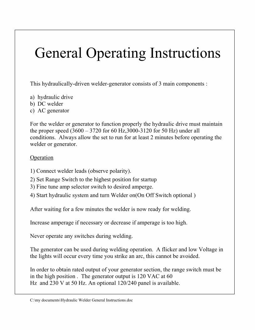
General Operating Instructions
This hydraulically-driven welder-generator consists of 3 main components :
a) hydraulic drive
b) DC welder
c) AC generator
For the welder or generator to function properly the hydraulic drive must maintain
the proper speed (3600 – 3720 for 60 Hz,3000-3120 for 50 Hz) under all
conditions. Always allow the set to run for at least 2 minutes before operating the
welder or generator.
Operation
1) Connect welder leads (observe polarity).
2) Set Range Switch to the highest position for startup3) Fine tune amp selector switch to desired amperge.
4) Start hydraulic system and turn Welder on(On Off Switch optional )
After waiting for a few minutes the welder is now ready for welding.
Increase amperage if necessary or decrease if amperage is too high.
Never operate any switches during welding.
The generator can be used during welding operation. A flicker and low Voltage in
the lights will occur every time you strike an arc, this cannot be avoided.
In order to obtain rated output of your generator section, the range switch must be
in the high position . The generator output is 120 VAC at 60
Hz and 230 V at 50 Hz. An optional 120/240 panel is available.
C:\my documents\Hydraulic Welder General Instructions.doc
.........
. . . . . . . . . . . . . . . . . . . . . . . . . . . .
Hydra – Weld ™
General Installation
The Hydra-Weld™ is a hydraulically-driven AC welder/generator that will deliver rated amperage when
the proper flow is delivered to it’s hydraulic drive. Oil temperature should be between 100-140˚F. A
10-micron filter is also recommended to maintain the drive at its maximum performance. Depending on
the size of the reservoir, an oil cooler must be used; the smaller the reservoir; the larger the cooler.
The tank should NEVER be smaller than 2 times the required GPM.
When starting a new hydraulic system, we strongly recommend that you connect the pressure line to the
return, bypassing the hydraulic welder drive. You should operate the system for 10 minutes that way.
This will clean the system; otherwise, all kinds of problems will occur. After connecting the pressure
and return line to the welder’s hydraulic drive, state your system at a low speed, slowly increasing the
speed until you reached the proper operating speed. While setting up a hydraulically-driven welder or
generator, it is necessary to check the speed setting of the hydraulic drive, since most systems will vary
in many ways (temperature – flow – viscosity / type of oil – etc.) from our test set up.
NEVER allow the welder to exceed 3900 RPM.
The return line pressure, under no circumstances, should reach 100 PSI or seal failure will occur.
The case drain must be connected directly to the tank (do NOT connect to the return line). We strongly
recommend that the case drain be connected to the upper portion of the tank. Making it easier for the
case drain oil to return to the tank. Return line must be ¾ or larger.
624 Harris Road
Ferndale, New York 12734
(845) 292-0800 (Phone)
(845) 292-0830 (Fax)
Manufacturer of high quality hydraulic generators and
welders (6/01)
Important Hydraulic
Circuit Installation
Information
If the hydraulically-driven welder/generator or
generator is mounted below the system tank, it is highly
recommended that a check valve with a very low cracking
pressure is installed in the case drain line (free flow motor
to tank, blocking tank to motor). This will eliminate seal
leakage during non-use time. It is also recommended that
the case drain be connected directly to the top of the tank
and not through a cooler or filter.
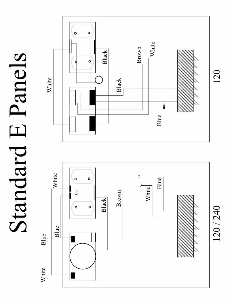
Sta
nd
ard
E P
anel
s
Cut
���������
���������
���������
Blu
e
Wh
ite
Bro
wn
Bla
ck
Blu
eW
hit
e
Blu
eW
hit
e
���������
���������
���������
Whit
e
Bla
ck
Bla
ck
Blu
eW
hit
e0
12
01
20
/ 2
40
Bro
wn
.........
. . . . . . . . . . . . . . . . . . . . . . . . . . . .
200-4 Operating Instructions
This welder is a hydraulically driven welder and it is extremely important that
the hydraulic system can supply the proper flow and pressure to maintain a
welder speed of 3,600 RPM under load. If the welder drops below 3600 RPM,
it cannot perform properly.
Start Hydraulic system
Turn welder hydraulic system on
Allow welder 2-3 minutes for warm-up
Be sure the red light between the 2 AC receptacles is lit
This will show you that the welder is close to the roper RPM and that you
have AC generator output
Insert welding leads into welding receptacles
CAUTION – Be sure that the positive cable is in the positive receptacle and
the negative cable in the negative receptive.
Set Range Selector switch to the position that is in the amperage range you
need for your welding job. Then set the Amp Selector switch to the amperage
that is nearest your desired amperage. Begin to weld. You may have to
switch one position up or down to get the desired amperage.
NEVER MOVE ANY SWITCHES DURNING WELDING
624 Harris Road
Ferndale, New York 12734
(845) 292-0800 (Phone)
(845) 292-0830 (Fax)
Manufacturer of high quality hydraulic generators and
welders
September 7, 2003
Page 2
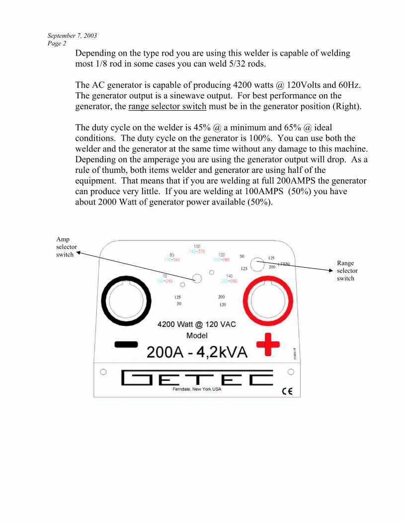
Depending on the type rod you are using this welder is capable of welding
most 1/8 rod in some cases you can weld 5/32 rods.
The AC generator is capable of producing 4200 watts @ 120Volts and 60Hz.
The generator output is a sinewave output. For best performance on the
generator, the range selector switch must be in the generator position (Right).
The duty cycle on the welder is 45% @ a minimum and 65% @ ideal
conditions. The duty cycle on the generator is 100%. You can use both the
welder and the generator at the same time without any damage to this machine.
Depending on the amperage you are using the generator output will drop. As a
rule of thumb, both items welder and generator are using half of the
equipment. That means that if you are welding at full 200AMPS the generator
can produce very little. If you are welding at 100AMPS (50%) you have
about 2000 Watt of generator power available (50%).
Amp
selector
switch
Range
selector
switch
.........
. . . . . . . . . . . . . . . . . . . . . . . . . . . .
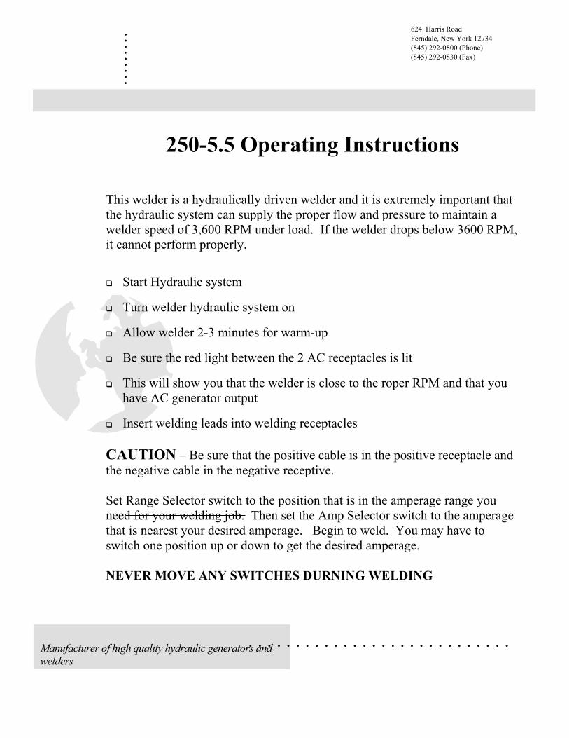
250-5.5 Operating Instructions
This welder is a hydraulically driven welder and it is extremely important that
the hydraulic system can supply the proper flow and pressure to maintain a
welder speed of 3,600 RPM under load. If the welder drops below 3600 RPM,
it cannot perform properly.
Start Hydraulic system
Turn welder hydraulic system on
Allow welder 2-3 minutes for warm-up
Be sure the red light between the 2 AC receptacles is lit
This will show you that the welder is close to the roper RPM and that you
have AC generator output
Insert welding leads into welding receptacles
CAUTION – Be sure that the positive cable is in the positive receptacle and
the negative cable in the negative receptive.
Set Range Selector switch to the position that is in the amperage range you
need for your welding job. Then set the Amp Selector switch to the amperage
that is nearest your desired amperage. Begin to weld. You may have to
switch one position up or down to get the desired amperage.
NEVER MOVE ANY SWITCHES DURNING WELDING
624 Harris Road
Ferndale, New York 12734
(845) 292-0800 (Phone)
(845) 292-0830 (Fax)
Manufacturer of high quality hydraulic generators and
welders
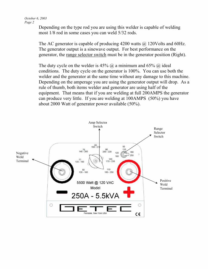
October 6, 2003
Page 2
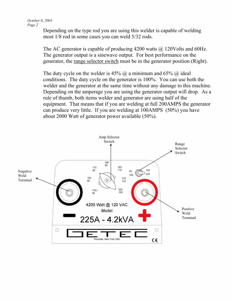
Depending on the type rod you are using this welder is capable of welding
most 1/8 rod in some cases you can weld 5/32 rods.
The AC generator is capable of producing 4200 watts @ 120Volts and 60Hz.
The generator output is a sinewave output. For best performance on the
generator, the range selector switch must be in the generator position (Right).
The duty cycle on the welder is 45% @ a minimum and 65% @ ideal
conditions. The duty cycle on the generator is 100%. You can use both the
welder and the generator at the same time without any damage to this machine.
Depending on the amperage you are using the generator output will drop. As a
rule of thumb, both items welder and generator are using half of the
equipment. That means that if you are welding at full 200AMPS the generator
can produce very little. If you are welding at 100AMPS (50%) you have
about 2000 Watt of generator power available (50%).
Amp Selector
Switch
Negative
Weld
Terminal
Range
Selector
Switch
Positive
Weld
Terminal
.........
. . . . . . . . . . . . . . . . . . . . . . . . . . . .
250-5.5 Operating Instructions
This welder is a hydraulically driven welder and it is extremely important that
the hydraulic system can supply the proper flow and pressure to maintain a
welder speed of 3,600 RPM under load. If the welder drops below 3600 RPM,
it cannot perform properly.
Start Hydraulic system
Turn welder hydraulic system on
Allow welder 2-3 minutes for warm-up
Be sure the red light between the 2 AC receptacles is lit
This will show you that the welder is close to the roper RPM and that you
have AC generator output
Insert welding leads into welding receptacles
CAUTION – Be sure that the positive cable is in the positive receptacle and
the negative cable in the negative receptive.
Set Range Selector switch to the position that is in the amperage range you
need for your welding job. Then set the Amp Selector switch to the amperage
that is nearest your desired amperage. Begin to weld. You may have to
switch one position up or down to get the desired amperage.
NEVER MOVE ANY SWITCHES DURNING WELDING
624 Harris Road
Ferndale, New York 12734
(845) 292-0800 (Phone)
(845) 292-0830 (Fax)
Manufacturer of high quality hydraulic generators and
welders
October 6, 2003
Page 2
Depending on the type rod you are using this welder is capable of welding
most 1/8 rod in some cases you can weld 5/32 rods.
The AC generator is capable of producing 4200 watts @ 120Volts and 60Hz.
The generator output is a sinewave output. For best performance on the
generator, the range selector switch must be in the generator position (Right).
The duty cycle on the welder is 45% @ a minimum and 65% @ ideal
conditions. The duty cycle on the generator is 100%. You can use both the
welder and the generator at the same time without any damage to this machine.
Depending on the amperage you are using the generator output will drop. As a
rule of thumb, both items welder and generator are using half of the
equipment. That means that if you are welding at full 200AMPS the generator
can produce very little. If you are welding at 100AMPS (50%) you have
about 2000 Watt of generator power available (50%).
Negative
Weld
Terminal
Amp Selector
Switch Range
Selector
Switch
Positive
Weld
Terminal
.........
. . . . . . . . . . . . . . . . . . . . . . . . . . . .
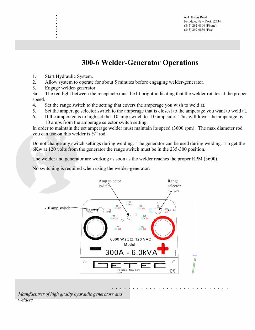
300-6 Welder-Generator Operations
1. Start Hydraulic System.
2. Allow system to operate for about 5 minutes before engaging welder-generator.
3. Engage welder-generator
3a. The red light between the receptacle must be lit bright indicating that the welder rotates at the proper
speed.
4. Set the range switch to the setting that covers the amperage you wish to weld at.
5. Set the amperage selector switch to the amperage that is closest to the amperage you want to weld at.
6. If the amperage is to high set the -10 amp switch to -10 amp side. This will lower the amperage by
10 amps from the amperage selector switch setting.
In order to maintain the set amperage welder must maintain its speed (3600 rpm). The max diameter rod
you can use on this welder is ¼” rod.
Do not change any switch settings during welding. The generator can be used during welding. To get the
6Kw at 120 volts from the generator the range switch must be in the 235-300 position.
The welder and generator are working as soon as the welder reaches the proper RPM (3600).
No switching is required when using the welder-generator.
300A - 6.0kVA
Model
6000 W att @ 120 VAC
Ferndale, New YorkUSA
624 Harris Road
Ferndale, New York 12734
(845) 292-0800 (Phone)
(845) 292-0830 (Fax)
Manufacturer of high quality hydraulic generators and
welders
-10 amp switch
Amp selector
switch
Range
selector
switch

September 7, 2003
Page 2
45÷2
00 A
dc
AU
XILI
ARY
WIN
DIN
G
-
WEL
DIN
GBR
IDG
E
+
THER
MA
LTR
IP
3
RA
NG
ESE
LEC
TOR
1
2
WEL
DIN
G C
URR
ENT
SELE
CTO
R
56
4
ALT
ERN
ATO
R W
IND
ING
WEL
DIN
G IM
PED
AN
CE
EXCI
TATI
ON
AC
BRID
GE
AC
-+
AC
AC
+ -
SLIP
RIN
G
RO
TOR
RED
BLA
CK
BLA
CK
RED
OR
AN
GE
WH
ITE
GREY
BLUE
WHITE
R/L1
WHITE
INSI
DE
THE
WIN
DIN
G
RED
BLACK
BROWN
YELLOW
BROWN
WELDING WINDING
BLACK
BLUE
BROWN+BLACK
BLUE
WHITE
BR
OW
NN
BLA
CK
BLUE
WHITE
240V
60Hz
120V
60Hz
7
ON
- O
FF
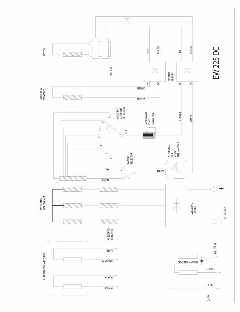
50¸ 2
25 A
dc
AU
XILI
ARY
WIN
DIN
G
-
WEL
DIN
GBR
IDG
E
WEL
DIN
GIM
PED
AN
CE
+
THER
MA
LTR
IP
3
RA
NG
ESE
LEC
TOR
12
1
2
WEL
DIN
G
SELE
CTO
RC
URR
ENT
56
7
4
EXCI
TOR
AC
BRID
GE
AC
-+
AC
AC
+ -
SLIP
RIN
G
RO
TOR
RED
BLA
CK
BLA
CK
RED
OR
AN
GE
WH
ITE
GREEN
GREEN
WHITE
R/L1
INSI
DE
THE
WIN
DIN
G
RED
BLACK
BLUE
BLACK
BROWN
WHITE
ALT
ERN
ATO
R W
IND
ING
WEL
DIN
GW
IND
ING
BROWN+BLACK
240V
BLUE
WHITE
NEU
TRA
L
OP
TIO
NA
LFI
NE
CO
NTR
OL
EW 2
25 D
C
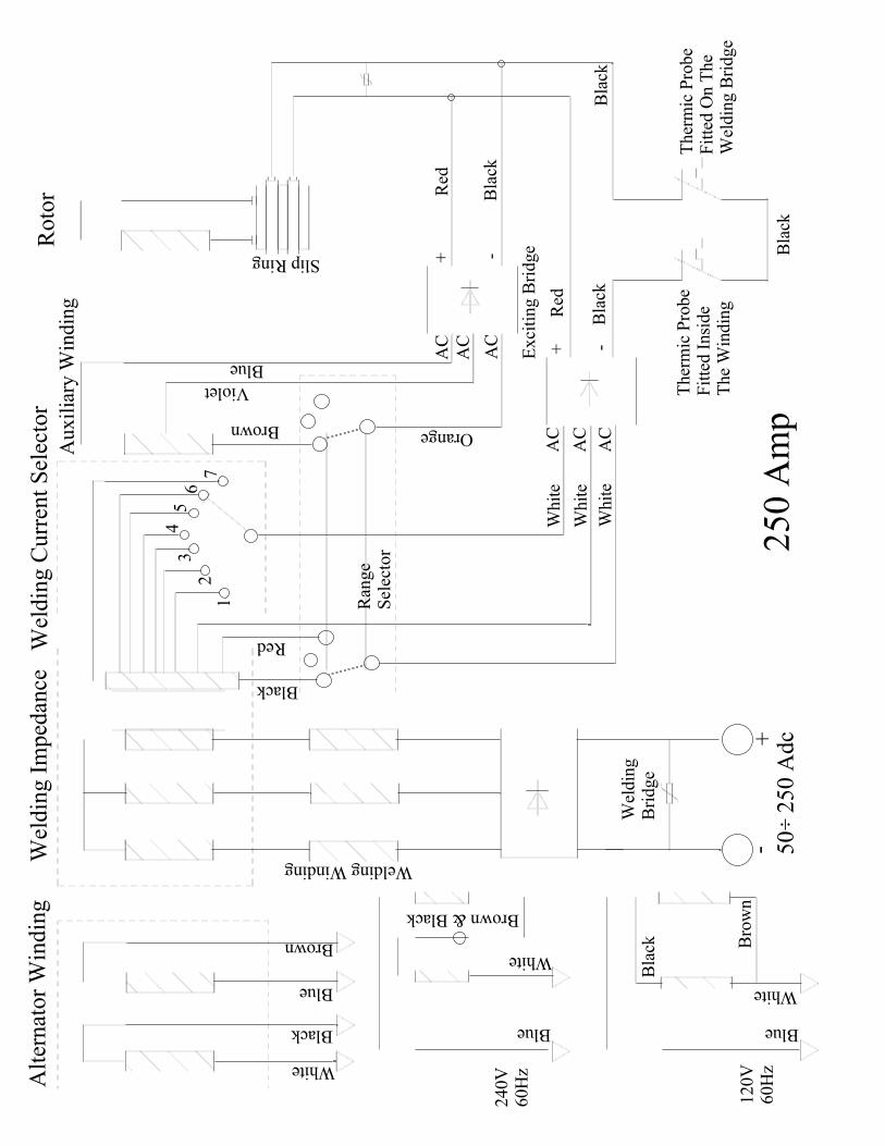
Alt
ern
ato
r W
ind
ing
White
Black
Brown
Blue
240V
60H
z
Blue
White
Brown & Black
120V
60H
z
Bla
ck Bro
wn
Blue
White
Wel
din
g I
mp
edan
ce
Welding Winding
Wel
din
gB
ridge
-+
50
2
50
Ad
c
Black
Red
76
54
32
1
Wel
din
g C
urr
ent
Sel
ecto
rA
uxil
iary
Win
din
g
AC
AC
AC
OrangeBrown
Violet
Blue Exci
ting B
ridge
Whit
e
Whit
e
Whit
eA
C
AC
AC
Roto
r
Slip Ring + -
Red
Bla
ck
Ran
ge
Sel
ecto
r
Bla
ck
Red
Bla
ck
Ther
mic
Pro
be
Fit
ted I
nsi
de
The
Win
din
g
Bla
ck
Ther
mic
Pro
be
Fit
ted O
n T
he
Wel
din
g B
ridge
+ -
25
0 A
mp
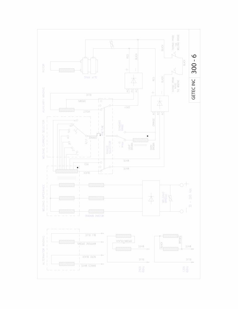
GET
ECIN
C30
0-6

200
- 22
5 -2
50 -
300
DC
Wel
der
Par
ts I
llus
tr.
13
12
11
109
1417
16
15
7
8a
5
6
4a
3
28
2726
6
21
22
23
24
2
8
5b
b
b
a
aa
39
4141
a
41d
41c
41e
42
43
44
45
46
47
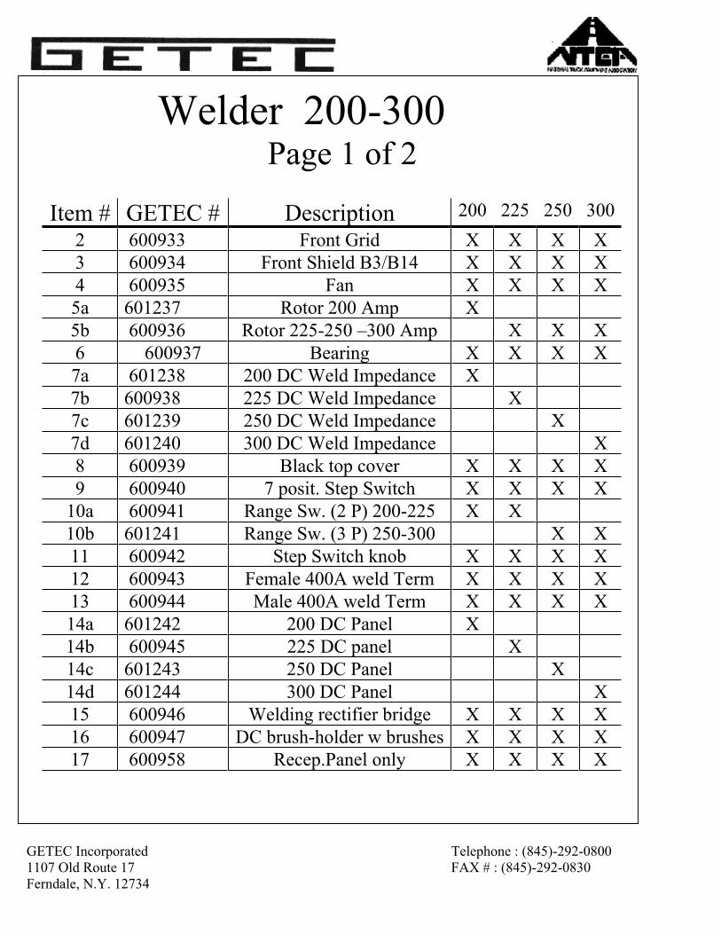
GETEC Incorporated Telephone : (845)-292-0800
1107 Old Route 17 FAX # : (845)-292-0830
Ferndale, N.Y. 12734
Welder 200-300Page 1 of 2
Item # GETEC # Description 200 225 250 300
2 600933 Front Grid X X X X
3 600934 Front Shield B3/B14 X X X X
4 600935 Fan X X X X
5a 601237 Rotor 200 Amp X
5b 600936 Rotor 225-250 –300 Amp X X X
6 600937 Bearing X X X X
7a 601238 200 DC Weld Impedance X
7b 600938 225 DC Weld Impedance X
7c 601239 250 DC Weld Impedance X
7d 601240 300 DC Weld Impedance X
8 600939 Black top cover X X X X
9 600940 7 posit. Step Switch X X X X
10a 600941 Range Sw. (2 P) 200-225 X X
10b 601241 Range Sw. (3 P) 250-300 X X
11 600942 Step Switch knob X X X X
12 600943 Female 400A weld Term X X X X
13 600944 Male 400A weld Term X X X X
14a 601242 200 DC Panel X
14b 600945 225 DC panel X
14c 601243 250 DC Panel X
14d 601244 300 DC Panel X
15 600946 Welding rectifier bridge X X X X
16 600947 DC brush-holder w brushes X X X X
17 600958 Recep.Panel only X X X X
GETEC Incorporated Telephone : (845)-292-0800
1107 Old Route 17 FAX # : (845)-292-0830
Ferndale, N.Y. 12734
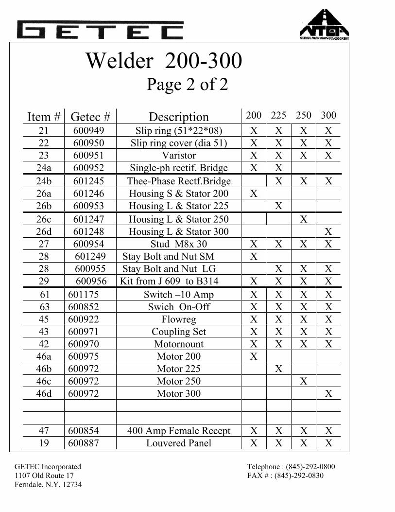
Welder 200-300Page 2 of 2
Item # Getec # Description 200 225 250 300
21 600949 Slip ring (51*22*08) X X X X
22 600950 Slip ring cover (dia 51) X X X X
23 600951 Varistor X X X X
24a 600952 Single-ph rectif. Bridge X X
24b 601245 Thee-Phase Rectf.Bridge X X X
26a 601246 Housing S & Stator 200 X
26b 600953 Housing L & Stator 225 X
26c 601247 Housing L & Stator 250 X
26d 601248 Housing L & Stator 300 X
27 600954 Stud M8x 30 X X X X
28 601249 Stay Bolt and Nut SM X
28 600955 Stay Bolt and Nut LG X X X
29 600956 Kit from J 609 to B314 X X X X
61 601175 Switch –10 Amp X X X X
63 600852 Swich On-Off X X X X
45 600922 Flowreg X X X X
43 600971 Coupling Set X X X X
42 600970 Motornount X X X X
46a 600975 Motor 200 X
46b 600972 Motor 225 X
46c 600972 Motor 250 X
46d 600972 Motor 300 X
47 600854 400 Amp Female Recept X X X X
19 600887 Louvered Panel X X X X
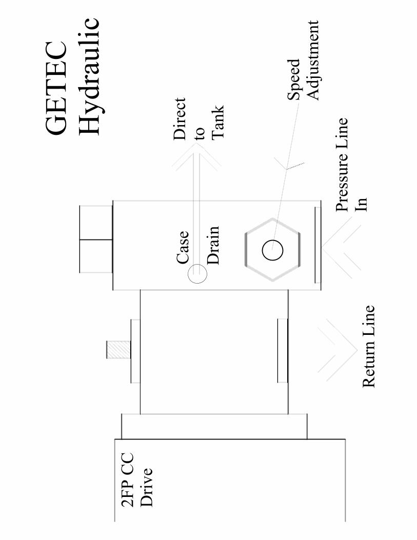
2F
P C
CD
riv
e
Ret
urn
Lin
e
Cas
e
Dra
in
Pre
ssure
Lin
eIn
Spee
dA
dju
stm
ent
GE
TE
CH
yd
rau
lic
Dir
ect
to Tan
k
.........
. . . . . . . . . . . . . . . . . . . . . . . . . . . .Getec’s Web Page(Addition 1)
http://www.getecinc.com
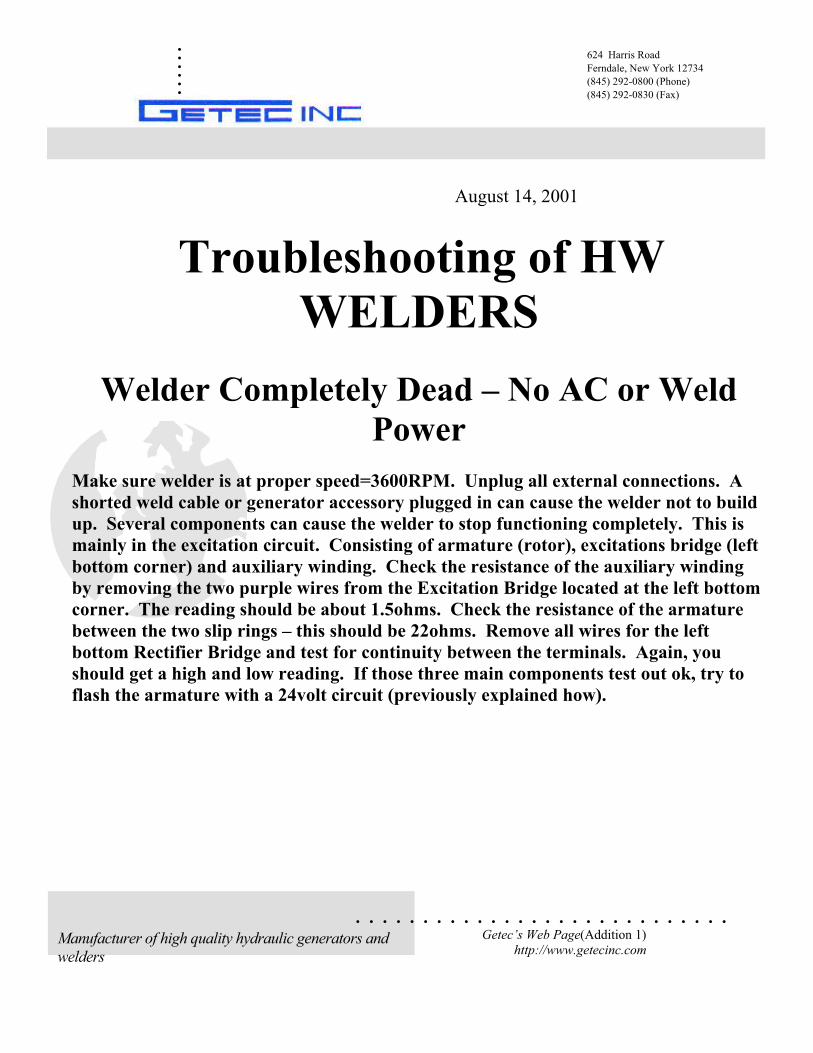
August 14, 2001
Troubleshooting of HW
WELDERS
Welder Completely Dead – No AC or Weld
Power
Make sure welder is at proper speed=3600RPM. Unplug all external connections. A
shorted weld cable or generator accessory plugged in can cause the welder not to build
up. Several components can cause the welder to stop functioning completely. This is
mainly in the excitation circuit. Consisting of armature (rotor), excitations bridge (left
bottom corner) and auxiliary winding. Check the resistance of the auxiliary winding
by removing the two purple wires from the Excitation Bridge located at the left bottom
corner. The reading should be about 1.5ohms. Check the resistance of the armature
between the two slip rings – this should be 22ohms. Remove all wires for the left
bottom Rectifier Bridge and test for continuity between the terminals. Again, you
should get a high and low reading. If those three main components test out ok, try to
flash the armature with a 24volt circuit (previously explained how).
624 Harris Road
Ferndale, New York 12734
(845) 292-0800 (Phone)
(845) 292-0830 (Fax)
Manufacturer of high quality hydraulic generators and
welders
.........
. . . . . . . . . . . . . . . . . . . . . . . . . . . .Getec’s Web Page(Addition 1)
http://www.getecinc.com
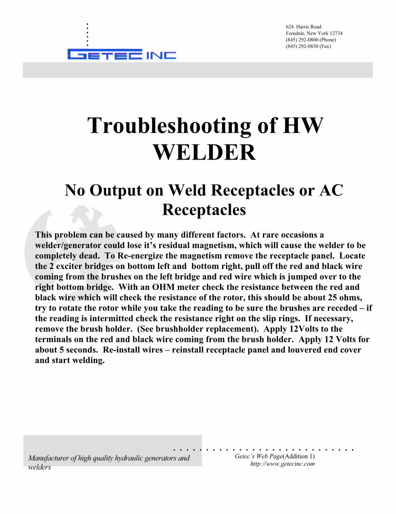
Troubleshooting of HW
WELDER
No Output on Weld Receptacles or AC
Receptacles
This problem can be caused by many different factors. At rare occasions a
welder/generator could lose it’s residual magnetism, which will cause the welder to be
completely dead. To Re-energize the magnetism remove the receptacle panel. Locate
the 2 exciter bridges on bottom left and bottom right, pull off the red and black wire
coming from the brushes on the left bridge and red wire which is jumped over to the
right bottom bridge. With an OHM meter check the resistance between the red and
black wire which will check the resistance of the rotor, this should be about 25 ohms,
try to rotate the rotor while you take the reading to be sure the brushes are receded – if
the reading is intermitted check the resistance right on the slip rings. If necessary,
remove the brush holder. (See brushholder replacement). Apply 12Volts to the
terminals on the red and black wire coming from the brush holder. Apply 12 Volts for
about 5 seconds. Re-install wires – reinstall receptacle panel and louvered end cover
and start welding.
624 Harris Road
Ferndale, New York 12734
(845) 292-0800 (Phone)
(845) 292-0830 (Fax)
Manufacturer of high quality hydraulic generators and
welders
.........
. . . . . . . . . . . . . . . . . . . . . . . . . . . .Getec’s Web Page(Addition 1)
http://www.getecinc.com
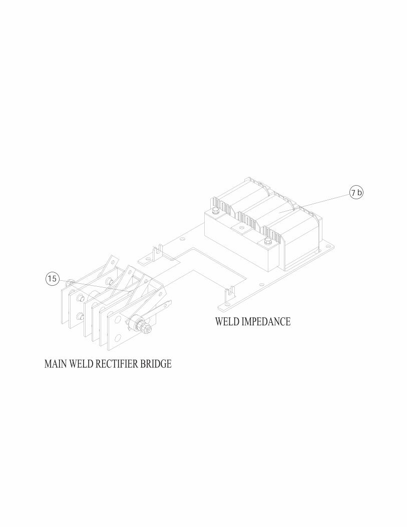
Troubleshooting of HW
WELDERS
No Output on Weld Receptacles but AC
Receptacle Output OK
If you have no welding power at all but the AC (120volts) is fully operational, this could
be caused by three components
The welding impedance (transformer)
The stator windings
The main welding rectifier bridge
Using the electrical diagram check for continuity of the welding impedance. By
disconnecting the three heavy lead wires from the main welding bridge rectifier, you
can check continuity between those three wires. In any combination, the resistance
should be between one and 2 ohms. All three readings should be the same. If you have
readings that determines that the stator winding and impedance winding are in good
condition. With the three wires removed, you can now check the resistance of the main
Rectifier Bridge. By measuring resistance between the three terminals forward and
reverse you always should get a high and a low reading, for example; if you measure
between one and two, if the first reading is very high the reverse reading should be
very low. You also can check the bridge by taking a resistance reading on the main
welding terminals. Again, you should have a high and low reading by reversing the
leads.
624 Harris Road
Ferndale, New York 12734
(845) 292-0800 (Phone)
(845) 292-0830 (Fax)
Manufacturer of high quality hydraulic generators and
welders
.........
. . . . . . . . . . . . . . . . . . . . . . . . . . . .Getec’s Web Page(Addition 1)
http://www.getecinc.com
Troubleshooting of HW
WELDERS
No AC Output but Weld Output
If the welder section functions properly but you have no AC output remove the
receptacle panel and make sure the white plugs are plugged solid. If there are
connected all the way, disconnect and make a resistance reading as follows
Blue to Brown (1.2ohm)
Black to White (1.2ohms)
If either one of those two readings is open the AC windings are defective. If they both
check out ok, check the receptacle and the wires going to the receptacles. To be certain
that is in the receptacle panel wiring, very carefully startup the welder and check for
120 volts between Blue and Brown and again 120 Volts between Black and White. If
you have 120 Volts pressing at those two readings, you must have a defective receptacle
or receptacle wiring.
624 Harris Road
Ferndale, New York 12734
(845) 292-0800 (Phone)
(845) 292-0830 (Fax)
Manufacturer of high quality hydraulic generators and
welders
.........
. . . . . . . . . . . . . . . . . . . . . . . . . . . .Getec’s Web Page(Addition 1)
http://www.getecinc.com
Troubleshooting of HW
WELDERS
Low Welding Amps
Low welding amps can be caused by three components
A defective Excitation Bridge located on the bottom right hand corner
B an open fine control (Optional). Resistance should be 6 ohms.
C Thermal trip in the windings. Disconnect the two AC wires off the bottom right
hand Excitation Bridge (white&orange) and make a resistance reading. With the
seven-step selector switch in the lowest position and the range switch and in the high
position you should get about 2 ohms. Move the seven-step switch while observing the
ohmmeter all the way to its highest position. The resistance should increase slightly
with every step. You should end up with about 3 ohms. If you do not start off with 2
ohms and the circuit shows open move your ohm meter 1 lead to the center terminal on
the range switch, the other ohm meter lead onto the terminal RL1 on the seven position
switch. If you have a reading, there about 2ohms the transformer is ok. To test for the
terimal trip in a windings take a reading between the center post of the range switch
and the white wire you remove from the Excitation Bridge. You should get 0ohms.
Any other readings on the trip is defective. To check the fine control put one-ohm
meter lead on the seven-step switch terminal RL1, the other lead on the orange wire
you removed from the Excitation Bridge. You should be able by moving the fine
control up and down adjust the ohmmeter reading between 0 and 6 ohms. To check
the Excitation Bridge, remove all wires from it and measure forward and backward
going around clockwise. In any position and in any combination between terminals
you should get a high and low reading. If any of the readings come out the same, the
bridge is defective.
624 Harris Road
Ferndale, New York 12734
(845) 292-0800 (Phone)
(845) 292-0830 (Fax)
Manufacturer of high quality hydraulic generators and
welders
.........
. . . . . . . . . . . . . . . . . . . . . . . . . . . .Getec’s Web Page(Addition 1)
http://www.getecinc.com
Troubleshooting of HW
WELDERS
Intermitting Welder Operation
Welder works properly for a few minutes and then stop operating but returns to full
welding power after several minutes of cooling off.
This will occur when the welder is operated past its duty cycle or in extreme high
ambient temperatures or if welder-cooling circuit is blocked. Be sure air intake is free
welder cooling might be affected by engine heat. Allow fresh air to enter louvered end
cover on welder. A cooling off period is 4-5 times longer if welder is turned off and
sitting still. Running it at its RPM will speed up the cooling and reset the internal
thermal trip.
624 Harris Road
Ferndale, New York 12734
(845) 292-0800 (Phone)
(845) 292-0830 (Fax)
Manufacturer of high quality hydraulic generators and
welders
.........
. . . . . . . . . . . . . . . . . . . . . . . . . . . .Getec’s Web Page(Addition 1)
http://www.getecinc.com
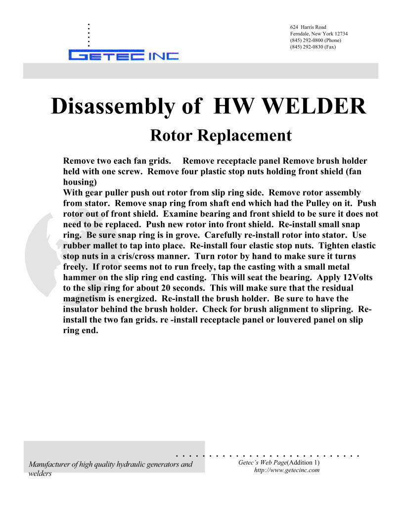
Disassembly of HW WELDER
Rotor Replacement
Remove two each fan grids. Remove receptacle panel Remove brush holder
held with one screw. Remove four plastic stop nuts holding front shield (fan
housing)
With gear puller push out rotor from slip ring side. Remove rotor assembly
from stator. Remove snap ring from shaft end which had the Pulley on it. Push
rotor out of front shield. Examine bearing and front shield to be sure it does not
need to be replaced. Push new rotor into front shield. Re-install small snap
ring. Be sure snap ring is in grove. Carefully re-install rotor into stator. Use
rubber mallet to tap into place. Re-install four elastic stop nuts. Tighten elastic
stop nuts in a cris/cross manner. Turn rotor by hand to make sure it turns
freely. If rotor seems not to run freely, tap the casting with a small metal
hammer on the slip ring end casting. This will seat the bearing. Apply 12Volts
to the slip ring for about 20 seconds. This will make sure that the residual
magnetism is energized. Re-install the brush holder. Be sure to have the
insulator behind the brush holder. Check for brush alignment to slipring. Re-
install the two fan grids. re -install receptacle panel or louvered panel on slip
ring end.
624 Harris Road
Ferndale, New York 12734
(845) 292-0800 (Phone)
(845) 292-0830 (Fax)
Manufacturer of high quality hydraulic generators and
welders
.........
. . . . . . . . . . . . . . . . . . . . . . . . . . . .Getec’s Web Page(Addition 1)
http://www.getecinc.com
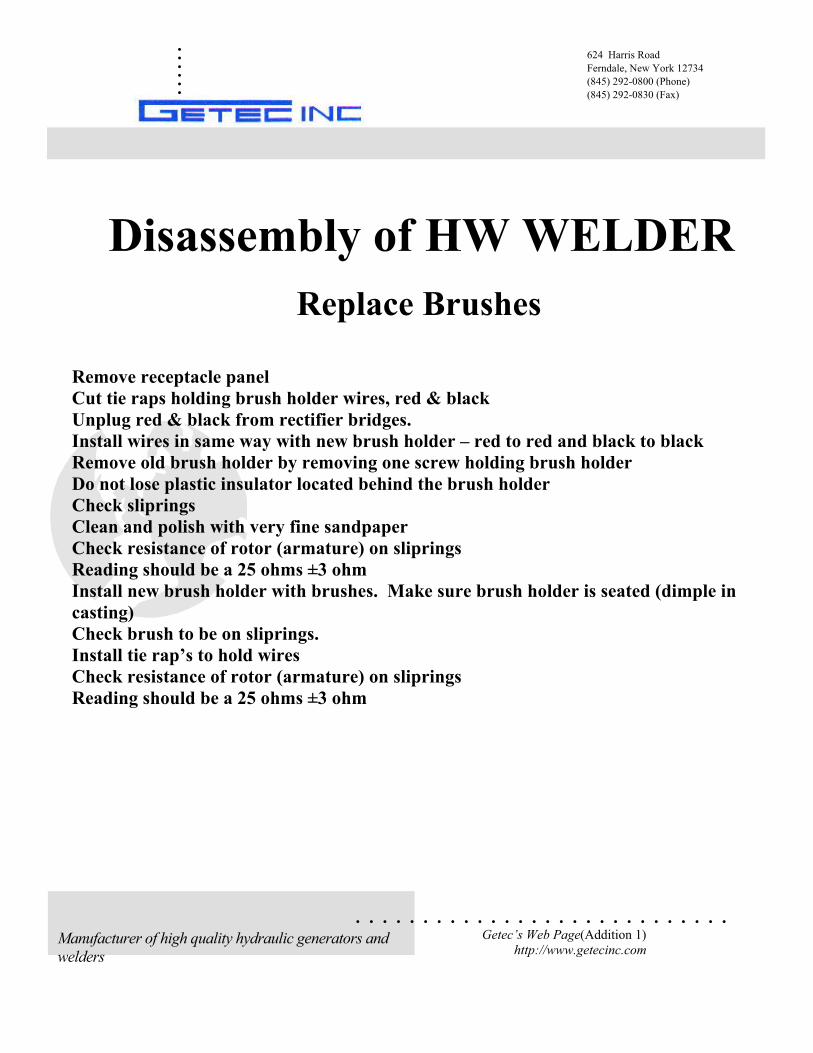
Disassembly of HW WELDER
Replace Brushes
Remove receptacle panel
Cut tie raps holding brush holder wires, red & black
Unplug red & black from rectifier bridges.
Install wires in same way with new brush holder – red to red and black to black
Remove old brush holder by removing one screw holding brush holder
Do not lose plastic insulator located behind the brush holder
Check sliprings
Clean and polish with very fine sandpaper
Check resistance of rotor (armature) on sliprings
Reading should be a 25 ohms ±3 ohm
Install new brush holder with brushes. Make sure brush holder is seated (dimple in
casting)
Check brush to be on sliprings.
Install tie rap’s to hold wires
Check resistance of rotor (armature) on sliprings
Reading should be a 25 ohms ±3 ohm
624 Harris Road
Ferndale, New York 12734
(845) 292-0800 (Phone)
(845) 292-0830 (Fax)
Manufacturer of high quality hydraulic generators and
welders
15
7 b
MAIN WELD RECTIFIER BRIDGE
WELD IMPEDANCE
A20
019
0
8
27
185
362
60
¯7
¯15
5
¯12
160
200
101203
142
540
135
200
625
225
680
250
680
300
680
Mod
elA
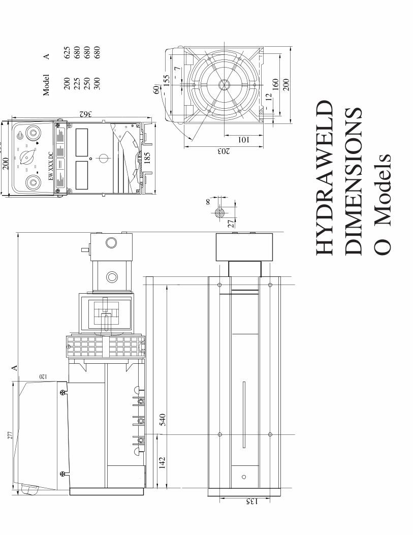
HY
DR
AW
EL
DD
IME
NSI
ON
SO
Mod
els
120
277
EWX
XX
DC


![Hydraulique [MA HYDR] - HES-SO](https://img.dokumen.tips/doc/110x75/62aeb5578aedff70f9094053/hydraulique-ma-hydr-hes-so.jpg)