Embed Size (px)
Citation preview
User Guide
Terminal Web User Interface
Evolution Release 4.1.x
iDirect 9-Series and iQ Desktop Satellite Routers
January 25, 2018
User Guide iDirect 9-Series and iQ Desktop Satellite Routers
ii User GuideiDirect 9-Series and iQ Desktop Satellite Routers | T0000946 | Rev A
Copyright © 2018, Inc. All rights reserved. Reproduction in whole or in part without permission is prohibited. Information contained herein is subject to change without notice. The specifications and information regarding the products in this document are subject to change without notice. All statements, information and recommendations in this document are believed to be accurate, but are presented without warranty of any kind, express, or implied. Users must take full responsibility for their application of any products. Trademarks, brand names and products mentioned in this document are the property of their respective owners. All such references are used strictly in an editorial fashion with no intent to convey any affiliation with the name or the product's rightful owner.
VT iDirect is a global leader in IP-based satellite communications providing technology and solutions that enable our partners worldwide to optimize their networks, differentiate their services and profitably expand their businesses. Our product portfolio, branded under the name iDirect, sets standards in performance and efficiency to deliver voice, video and data connectivity anywhere in the world. VT iDirect is the world’s largest TDMA enterprise VSAT manufacturer and is the leader in key industries including mobility, military/government and cellular backhaul.
VT iDirectCompany Web site: http://www.idirect.net ~ Main Phone: 703.648.8000TAC Contact Information: Phone: 703.648.8151 ~ Email: [email protected] ~ Web site: http://tac.idirect.net
iDirect Government™, created in 2007, is a wholly owned subsidiary of iDirect and was formed to better serve the U.S. government and defense communities.
iDirect Government™Company Web site: http://www.idirectgov.com ~ Main Phone: 703.648.8118TAC Contact Information: Phone: 703.648.8111 ~ Email: [email protected] ~ Web site: http://tac.idirectgov.com
Document Name: UG_TerminalWUI_Evo4.1.x_T0000946_RevB_01252018.pdf
Document Part Number: T0000946
Revision History
Revision History
The following table shows all revisions for this document. To determine if this is the latest revision, check the Technical Assistance Center (TAC) Web site. Refer to Getting Help on page x for TAC access information.
Revision Date Updates
A 11/15/2017 Initial release of the document for iDX Release 4.1.x.
B 01/25/2018 Removed all CX780 references from the document since it is no longer supported in Evolution platform.
User Guide iiiiDirect 9-Series and iQ Desktop Satellite Routers | T0000946 | Rev A

Revision History
iv User GuideiDirect 9-Series and iQ Desktop Satellite Routers | T0000946 | Rev A
Contents
Contents
Revision History . . . . . . . . . . . . . . . . . . . . . . . . . . . . . . . . . . . . . . . . . . . . . . . . iii
Figures. . . . . . . . . . . . . . . . . . . . . . . . . . . . . . . . . . . . . . . . . . . . . . . . . . . . . . . .viii
Tables . . . . . . . . . . . . . . . . . . . . . . . . . . . . . . . . . . . . . . . . . . . . . . . . . . . . . . . . ix
About. . . . . . . . . . . . . . . . . . . . . . . . . . . . . . . . . . . . . . . . . . . . . . . . . . . . . . . . . xi
Intended Audience. . . . . . . . . . . . . . . . . . . . . . . . . . . . . . . . . . . . . . . . . . . . . . . xi
Manual Contents . . . . . . . . . . . . . . . . . . . . . . . . . . . . . . . . . . . . . . . . . . . . . . . . xi
Document Conventions . . . . . . . . . . . . . . . . . . . . . . . . . . . . . . . . . . . . . . . . . . . . xii
Related Documents . . . . . . . . . . . . . . . . . . . . . . . . . . . . . . . . . . . . . . . . . . . . . . xii
Related Training Services . . . . . . . . . . . . . . . . . . . . . . . . . . . . . . . . . . . . . . . . . .xiii
Getting Help . . . . . . . . . . . . . . . . . . . . . . . . . . . . . . . . . . . . . . . . . . . . . . . . . . .xiii
Chapter 1 Introduction . . . . . . . . . . . . . . . . . . . . . . . . . . . . . . . . . . . . . . . . . 1
1.1 Supported Routers . . . . . . . . . . . . . . . . . . . . . . . . . . . . . . . . . . . . . . . . . . . 1
1.2 Terminal Web User Interface . . . . . . . . . . . . . . . . . . . . . . . . . . . . . . . . . . . . 1
1.2.1 Terminal WUI Features . . . . . . . . . . . . . . . . . . . . . . . . . . . . . . . . . . . . . 1
1.3 Terminal Web User Interface Login . . . . . . . . . . . . . . . . . . . . . . . . . . . . . . . . 2
1.4 Connecting to the Terminal WUI . . . . . . . . . . . . . . . . . . . . . . . . . . . . . . . . . . 2
1.4.1 Manually Configuring the Windows Host to Connect to the Satellite Router . . 3
1.5 Starting a Terminal WUI Session . . . . . . . . . . . . . . . . . . . . . . . . . . . . . . . . . . 6
1.5.1 Simulated LEDs . . . . . . . . . . . . . . . . . . . . . . . . . . . . . . . . . . . . . . . . . . 7
User Guide viDirect 9-Series and iQ Desktop Satellite Routers | T0000946 | Rev A
Contents
Chapter 2 Terminal Web User Interface. . . . . . . . . . . . . . . . . . . . . . . . . . . 9
2.1 Dashboard . . . . . . . . . . . . . . . . . . . . . . . . . . . . . . . . . . . . . . . . . . . . . . . . 9
2.2 Details Menu . . . . . . . . . . . . . . . . . . . . . . . . . . . . . . . . . . . . . . . . . . . . . . 11
2.2.1 Satellite Interface . . . . . . . . . . . . . . . . . . . . . . . . . . . . . . . . . . . . . . . 11
2.2.1.1 Satellite Interface - Reporting and Configuration . . . . . . . . . . . . . . . 11
2.2.2 Terminal/Device . . . . . . . . . . . . . . . . . . . . . . . . . . . . . . . . . . . . . . . . 13
2.2.2.1 Terminal Device - Reporting and Configuration . . . . . . . . . . . . . . . . 13
2.2.3 LAN Interface . . . . . . . . . . . . . . . . . . . . . . . . . . . . . . . . . . . . . . . . . . 14
2.2.3.1 LAN Interface - Reporting (LAN Ports). . . . . . . . . . . . . . . . . . . . . . . 15
2.2.3.2 LAN Interface - IP Configuration VLANs . . . . . . . . . . . . . . . . . . . . . . 16
2.2.4 External Equipment . . . . . . . . . . . . . . . . . . . . . . . . . . . . . . . . . . . . . . 17
2.2.4.1 External Equipment - Antenna . . . . . . . . . . . . . . . . . . . . . . . . . . . 17
2.2.4.2 External Equipment - LNB . . . . . . . . . . . . . . . . . . . . . . . . . . . . . . 18
2.3 Administration . . . . . . . . . . . . . . . . . . . . . . . . . . . . . . . . . . . . . . . . . . . . 19
2.3.1 Software and Configuration. . . . . . . . . . . . . . . . . . . . . . . . . . . . . . . . . 19
2.3.1.1 Loading Packages using the Terminal WUI . . . . . . . . . . . . . . . . . . . . 19
2.3.1.2 Loading Option Files using the Terminal WUI . . . . . . . . . . . . . . . . . . 20
2.4 Commissioning . . . . . . . . . . . . . . . . . . . . . . . . . . . . . . . . . . . . . . . . . . . . 21
2.4.1 Commissioning Wizard . . . . . . . . . . . . . . . . . . . . . . . . . . . . . . . . . . . . 21
2.4.2 Commissioning Details . . . . . . . . . . . . . . . . . . . . . . . . . . . . . . . . . . . . 21
2.4.3 Angle Calculator . . . . . . . . . . . . . . . . . . . . . . . . . . . . . . . . . . . . . . . . 23
2.4.4 Antenna Pointing. . . . . . . . . . . . . . . . . . . . . . . . . . . . . . . . . . . . . . . . 24
2.4.5 Cross Polarization/P1dB . . . . . . . . . . . . . . . . . . . . . . . . . . . . . . . . . . . 25
Chapter 3 Commissioning a Terminal . . . . . . . . . . . . . . . . . . . . . . . . . . . . 27
3.1 Introduction . . . . . . . . . . . . . . . . . . . . . . . . . . . . . . . . . . . . . . . . . . . . . . 27
3.2 Software Upgrade . . . . . . . . . . . . . . . . . . . . . . . . . . . . . . . . . . . . . . . . . . 28
3.3 Manual Antenna Pointing (without OpenAMIP) . . . . . . . . . . . . . . . . . . . . . . . . 28
Selecting a Site . . . . . . . . . . . . . . . . . . . . . . . . . . . . . . . . . . . . . . . . . . . . 28
Assembly . . . . . . . . . . . . . . . . . . . . . . . . . . . . . . . . . . . . . . . . . . . . . . . . 28
Orientation. . . . . . . . . . . . . . . . . . . . . . . . . . . . . . . . . . . . . . . . . . . . . . . 29
Magnetic Variation . . . . . . . . . . . . . . . . . . . . . . . . . . . . . . . . . . . . . . . . . . 29
vi User GuideiDirect 9-Series and iQ Desktop Satellite Routers | T0000946 | Rev A
Contents
Sighting Antenna Azimuth . . . . . . . . . . . . . . . . . . . . . . . . . . . . . . . . . . . . . 30
Elevation Offset. . . . . . . . . . . . . . . . . . . . . . . . . . . . . . . . . . . . . . . . . . . . 30
Using the Terminal WUI . . . . . . . . . . . . . . . . . . . . . . . . . . . . . . . . . . . . . . . . . 32
3.4 Cross-Polarization Test . . . . . . . . . . . . . . . . . . . . . . . . . . . . . . . . . . . . . . . 33
Overview. . . . . . . . . . . . . . . . . . . . . . . . . . . . . . . . . . . . . . . . . . . . . . . . . . . 33
Satellite Access . . . . . . . . . . . . . . . . . . . . . . . . . . . . . . . . . . . . . . . . . . . . . . 34
Preparation . . . . . . . . . . . . . . . . . . . . . . . . . . . . . . . . . . . . . . . . . . . . . . 34
Performing Cross-Pol Adjustment. . . . . . . . . . . . . . . . . . . . . . . . . . . . . . . . . . . 35
After Securing the Antenna. . . . . . . . . . . . . . . . . . . . . . . . . . . . . . . . . . . . . . . 36
Using the Terminal WUI . . . . . . . . . . . . . . . . . . . . . . . . . . . . . . . . . . . . . . . . . 36
Appendix A Acronyms and Abbreviations. . . . . . . . . . . . . . . . . . . . . . . . . . 39
Appendix B Remote Locking. . . . . . . . . . . . . . . . . . . . . . . . . . . . . . . . . . . . . 43
B.1 Locking an iQ Desktop. . . . . . . . . . . . . . . . . . . . . . . . . . . . . . . . . . . . . . . . 44
B.2 Configuring the Network Key . . . . . . . . . . . . . . . . . . . . . . . . . . . . . . . . . . . 44
B.3 Performing a Temporary Lock . . . . . . . . . . . . . . . . . . . . . . . . . . . . . . . . . . 44
B.4 Performing a Soft Lock . . . . . . . . . . . . . . . . . . . . . . . . . . . . . . . . . . . . . . . 46
B.5 Performing a Hard Lock. . . . . . . . . . . . . . . . . . . . . . . . . . . . . . . . . . . . . . . 48
B.6 Non-Warranty RMA Required to Remove Remote Locks . . . . . . . . . . . . . . . . . . 49
User Guide viiiDirect 9-Series and iQ Desktop Satellite Routers | T0000946 | Rev A
Figures
viii User GuideiDirect 9-Series and iQ Desktop Satellite Routers | T0000946 | Rev A
Figures
Figure 1-1. WUI Log-In Screen . . . . . . . . . . . . . . . . . . . . . . . . . . . . . . . . . . . . . . . . . . . . 2
Figure 1-2. Network and Sharing Center . . . . . . . . . . . . . . . . . . . . . . . . . . . . . . . . . . . . . 3
Figure 1-3. Local Area Connection Status . . . . . . . . . . . . . . . . . . . . . . . . . . . . . . . . . . . . . 4
Figure 1-4. Local Area Connection Properties Window . . . . . . . . . . . . . . . . . . . . . . . . . . . . 5
Figure 1-5. Internet Protocol Version 4 Properties . . . . . . . . . . . . . . . . . . . . . . . . . . . . . . . 6
Figure 1-6. Terminal WUI Dashboard . . . . . . . . . . . . . . . . . . . . . . . . . . . . . . . . . . . . . . . . 7
Figure 1-7. LED Indicators . . . . . . . . . . . . . . . . . . . . . . . . . . . . . . . . . . . . . . . . . . . . . . . 7
Figure 2-1. Dashboard Menu . . . . . . . . . . . . . . . . . . . . . . . . . . . . . . . . . . . . . . . . . . . . . 9
Figure 2-2. Details Menu . . . . . . . . . . . . . . . . . . . . . . . . . . . . . . . . . . . . . . . . . . . . . . 11
Figure 2-3. Satellite Interface - Reporting and Configuration . . . . . . . . . . . . . . . . . . . . . . . 11
Figure 2-4. Terminal Device - Reporting and Configuration . . . . . . . . . . . . . . . . . . . . . . . . 13
Figure 2-5. LAN Interface - Reporting (LAN Ports) . . . . . . . . . . . . . . . . . . . . . . . . . . . . . . 15
Figure 2-6. LAN Interface - IP Configuration VLANs . . . . . . . . . . . . . . . . . . . . . . . . . . . . . 16
Figure 2-7. External Equipment - Antenna . . . . . . . . . . . . . . . . . . . . . . . . . . . . . . . . . . . 17
Figure 2-8. External Equipment - LNB . . . . . . . . . . . . . . . . . . . . . . . . . . . . . . . . . . . . . . 18
Figure 2-9. Administration Menu . . . . . . . . . . . . . . . . . . . . . . . . . . . . . . . . . . . . . . . . . 19
Figure 2-10. Upload Software Packages. . . . . . . . . . . . . . . . . . . . . . . . . . . . . . . . . . . . . . 20
Figure 2-11. Commissioning Menu . . . . . . . . . . . . . . . . . . . . . . . . . . . . . . . . . . . . . . . . . 21
Figure 2-12. Commissioning Details . . . . . . . . . . . . . . . . . . . . . . . . . . . . . . . . . . . . . . . . 21
Figure 2-13. Angle Calculator . . . . . . . . . . . . . . . . . . . . . . . . . . . . . . . . . . . . . . . . . . . . 23
Figure 2-14. Antenna Pointing . . . . . . . . . . . . . . . . . . . . . . . . . . . . . . . . . . . . . . . . . . . . 24
Figure 2-15. Cross Polarization . . . . . . . . . . . . . . . . . . . . . . . . . . . . . . . . . . . . . . . . . . . 25
Figure 3-1. Commissioning Menu . . . . . . . . . . . . . . . . . . . . . . . . . . . . . . . . . . . . . . . . . 27
Figure 3-2. Commissioning Wizard . . . . . . . . . . . . . . . . . . . . . . . . . . . . . . . . . . . . . . . . 28
Figure 3-3. Example: Magnetic Declination. . . . . . . . . . . . . . . . . . . . . . . . . . . . . . . . . . . 29
Figure 3-4. Antenna Elevation Offset. . . . . . . . . . . . . . . . . . . . . . . . . . . . . . . . . . . . . . . 31
Figure 3-5. Antenna Pointing . . . . . . . . . . . . . . . . . . . . . . . . . . . . . . . . . . . . . . . . . . . . 32
Figure 3-6. Configure Downstream . . . . . . . . . . . . . . . . . . . . . . . . . . . . . . . . . . . . . . . . 32
Figure 3-7. Antenna Pointing . . . . . . . . . . . . . . . . . . . . . . . . . . . . . . . . . . . . . . . . . . . . 33
Figure 3-8. Terminal WUI Cross Polarization Page . . . . . . . . . . . . . . . . . . . . . . . . . . . . . . 34
Figure 3-9. Cross Polarization test . . . . . . . . . . . . . . . . . . . . . . . . . . . . . . . . . . . . . . . . 36
Figure 3-10. Exit Commissioning Mode . . . . . . . . . . . . . . . . . . . . . . . . . . . . . . . . . . . . . . 37
Figure 3-11. Commissioning Complete. . . . . . . . . . . . . . . . . . . . . . . . . . . . . . . . . . . . . . . 37
Figure B-1. Network Lock Page. . . . . . . . . . . . . . . . . . . . . . . . . . . . . . . . . . . . . . . . . . . 45
Figure B-2. Entering the Confirmation Word . . . . . . . . . . . . . . . . . . . . . . . . . . . . . . . . . . 46
Figure B-3. Soft Lock Admin Netlock . . . . . . . . . . . . . . . . . . . . . . . . . . . . . . . . . . . . . . . 47
Figure B-4. Network Lock Page. . . . . . . . . . . . . . . . . . . . . . . . . . . . . . . . . . . . . . . . . . . 48

Tables
Tables
Table 2-1. Dashboard Menu Items . . . . . . . . . . . . . . . . . . . . . . . . . . . . . . . . . . . . . . . . . 10
Table 2-2. Satellite Interface - Reporting and Configuration Field Descriptions . . . . . . . . . . . 12
Table 2-3. Terminal Device - Reporting and Configuration Field Descriptions . . . . . . . . . . . . 14
Table 2-4. LAN Interface - Reporting (LAN Ports) Field Descriptions. . . . . . . . . . . . . . . . . . . 15
Table 2-5. IP Configuration VLANs Field Descriptions . . . . . . . . . . . . . . . . . . . . . . . . . . . . 16
Table 2-6. LNB Field Descriptions . . . . . . . . . . . . . . . . . . . . . . . . . . . . . . . . . . . . . . . . . 18
Table 2-7. Commissioning Details . . . . . . . . . . . . . . . . . . . . . . . . . . . . . . . . . . . . . . . . . 22
Table 2-8. Angle Calculator . . . . . . . . . . . . . . . . . . . . . . . . . . . . . . . . . . . . . . . . . . . . . 23
Table 2-9. Antenna Pointing. . . . . . . . . . . . . . . . . . . . . . . . . . . . . . . . . . . . . . . . . . . . . 24
Table 2-10. Cross Polarization . . . . . . . . . . . . . . . . . . . . . . . . . . . . . . . . . . . . . . . . . . . . 25
User Guide ixiDirect 9-Series and iQ Desktop Satellite Routers | T0000946 | Rev A

Tables
x User GuideiDirect 9-Series and iQ Desktop Satellite Routers | T0000946 | Rev A
About
This chapter contains the following sections:
• Intended Audience
• Manual Contents
• Document Conventions
• Related Documents
• Related Training Services
• Getting Help
Intended AudienceThe Terminal WUI User Guide is for iDirect network operators or installers to connect directly to an iQ Desktop satellite router. This may include installers responsible for Terminal commissioning, network operators connecting remotely, or on-site personnel working with iDirect to troubleshoot network problems.
Manual ContentsIn addition to the information in this chapter, this manual also includes the following:
• Chapter 1, Introduction on page 1, provides information about what the terminal WUI is, the supported routers, the login details, and the LED information.
• Chapter 2, Terminal Web User Interface provides information on how to connect to the terminal WUI and provides information on the terminal WUI and explains each one of the tabs in-detail.
• Chapter 3, Commissioning a Terminal provides information on how to commission a new remote using the terminal WUI.
NOTE: A basic list of acronyms and abbreviations can be found in Appendix A, Acronyms and Abbreviations.
User Guide xiiDirect 9-Series and iQ Desktop Satellite Routers | T0000946 | Rev A
Document Conventions
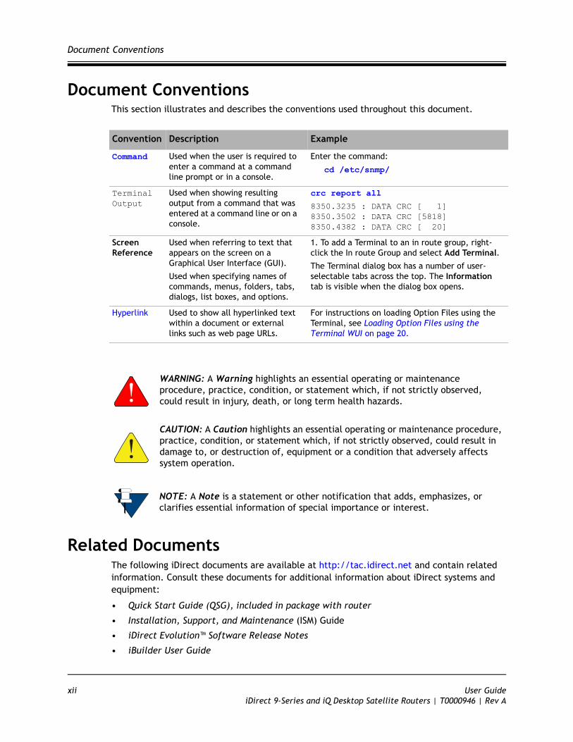
Document ConventionsThis section illustrates and describes the conventions used throughout this document.
Related DocumentsThe following iDirect documents are available at http://tac.idirect.net and contain related information. Consult these documents for additional information about iDirect systems and equipment:
• Quick Start Guide (QSG), included in package with router
• Installation, Support, and Maintenance (ISM) Guide
• iDirect Evolution™ Software Release Notes
• iBuilder User Guide
Convention Description Example
Command Used when the user is required to enter a command at a command line prompt or in a console.
Enter the command:
cd /etc/snmp/
Terminal Output
Used when showing resulting output from a command that was entered at a command line or on a console.
crc report all
8350.3235 : DATA CRC [ 1]8350.3502 : DATA CRC [5818]8350.4382 : DATA CRC [ 20]
Screen Reference
Used when referring to text that appears on the screen on a Graphical User Interface (GUI).
Used when specifying names of commands, menus, folders, tabs, dialogs, list boxes, and options.
1. To add a Terminal to an in route group, right-click the In route Group and select Add Terminal.
The Terminal dialog box has a number of user-selectable tabs across the top. The Information tab is visible when the dialog box opens.
Hyperlink Used to show all hyperlinked text within a document or external links such as web page URLs.
For instructions on loading Option Files using the Terminal, see Loading Option Files using the Terminal WUI on page 20.
WARNING: A Warning highlights an essential operating or maintenance procedure, practice, condition, or statement which, if not strictly observed, could result in injury, death, or long term health hazards.
CAUTION: A Caution highlights an essential operating or maintenance procedure, practice, condition, or statement which, if not strictly observed, could result in damage to, or destruction of, equipment or a condition that adversely affects system operation.
NOTE: A Note is a statement or other notification that adds, emphasizes, or clarifies essential information of special importance or interest.
xii User GuideiDirect 9-Series and iQ Desktop Satellite Routers | T0000946 | Rev A

Related Training Services
• iMonitor User Guide
• iDX Technical Reference Guide
Related Training ServicesiDirect offers scheduled classroom training at various global training centers, as well as eLearning, in the installation, operation, maintenance and management of iDirect satellite networks. For training course descriptions and available training dates visit the iDirect web site Training and Services at: http://www.idirect.net/Training-and-Services.aspx or call +1 (800) 648-8240 for class registration and information.
Getting HelpThe iDirect Technical Assistance Center (TAC) and the iDirect Government Technical Assistance Center (TAC) are available to provide assistance 24 hours a day, 365 days a year. Software user guides, installation procedures, FAQs, and other documents that support iDirect and iDirect Government products are available on the respective TAC Web site:
• Access the iDirect TAC Web site at http://tac.idirect.net
• Access the iDirect Government TAC Web site at http://tac.idirectgov.com
The iDirect TAC may be contacted by telephone or email:
• Telephone: 703.648.8151
• E-mail: [email protected]
The iDirect Government TAC may be contacted by telephone or email:
• Telephone: 703.648.8111
• Email: [email protected]
iDirect and iDirect Government produce documentation that are technically accurate, easy to use, and helpful to our customers. Please assist us in improving this document by providing feedback. Send comments to:
• iDirect: [email protected]
• iDirect Government: [email protected]
For sales or product purchasing information contact iDirect Corporate Sales at the following telephone number or e-mail address:
• Telephone: 703.648.8000
• E-mail: [email protected]
User Guide xiiiiDirect 9-Series and iQ Desktop Satellite Routers | T0000946 | Rev A

Getting Help
xiv User GuideiDirect 9-Series and iQ Desktop Satellite Routers | T0000946 | Rev A
1 Introduction
This chapter provides a general overview of the Terminal Web User Interface (WUI).
• Section 1.1, Supported Routers on page 1
• Section 1.2, Terminal Web User Interface on page 1
• Section 1.3, Terminal Web User Interface Login on page 2
• Section 1.4, Connecting to the Terminal WUI on page 2
• Section 1.5, Starting a Terminal WUI Session on page 6
1.1 Supported RoutersThe Terminal WUI is supported on the iDirect 9-Series and iQ Desktop Satellite Routers.
1.2 Terminal Web User InterfaceThe Terminal Web User Interface (WUI) provides users with secure means to monitor satellite routers from the local area network (LAN) side.
The Terminal WUI also provides configuration and real-time status and statistical information about the satellite routers. Terminal WUI provides interaction with the satellite router, enabling configuration, commissioning, and monitoring without a direct connection with the iVantage NMS. The level of functionality available to the user is determined by the login access (admin or user).
1.2.1 Terminal WUI FeaturesTerminal WUI provides the following features:
• LED indicators that display real-time status of the satellite router
• A dashboard view of high-level satellite router information (for example, displays if a satellite router is in network or locked to the satellite)
• A status and monitoring view that provides status and monitoring information about the satellite router in real-time for modem information, events, Ethernet receive and transmit connections, and Internet Protocol (IP) configuration and information
• Administration tools for loading software packages and options files
• A wizard for commissioning new remotes
User Guide 1iDirect 9-Series and iQ Desktop Satellite Routers | T0000946 | Rev A

Terminal Web User Interface Login
1.3 Terminal Web User Interface LoginThe Terminal WUI supports two levels of log-in; a generic user level, and an administrator level. The log-in screen is shown in Figure 1-1.
Figure 1-1. WUI Log-In Screen
The default login credentials for the two configured user accounts admin and user are:
Username: admin
Password: iDirect
1.4 Connecting to the Terminal WUITerminal WUI may be used at any time to access the Satellite Routers. All that is necessary is the IP address assigned to the satellite router and a physical Ethernet connection to the LAN port.
Default factory settings for the Satellite Routers are shown below:
• LAN IP Address: 192.168.0.1
• Subnet mask: 255.255.255.0
NOTE: The password specified above is just an example and the actual password is the one that is configured in iBuilder. Username and password are both case sensitive.
2 User GuideiDirect 9-Series and iQ Desktop Satellite Routers | T0000946 | Rev A
Connecting to the Terminal WUI
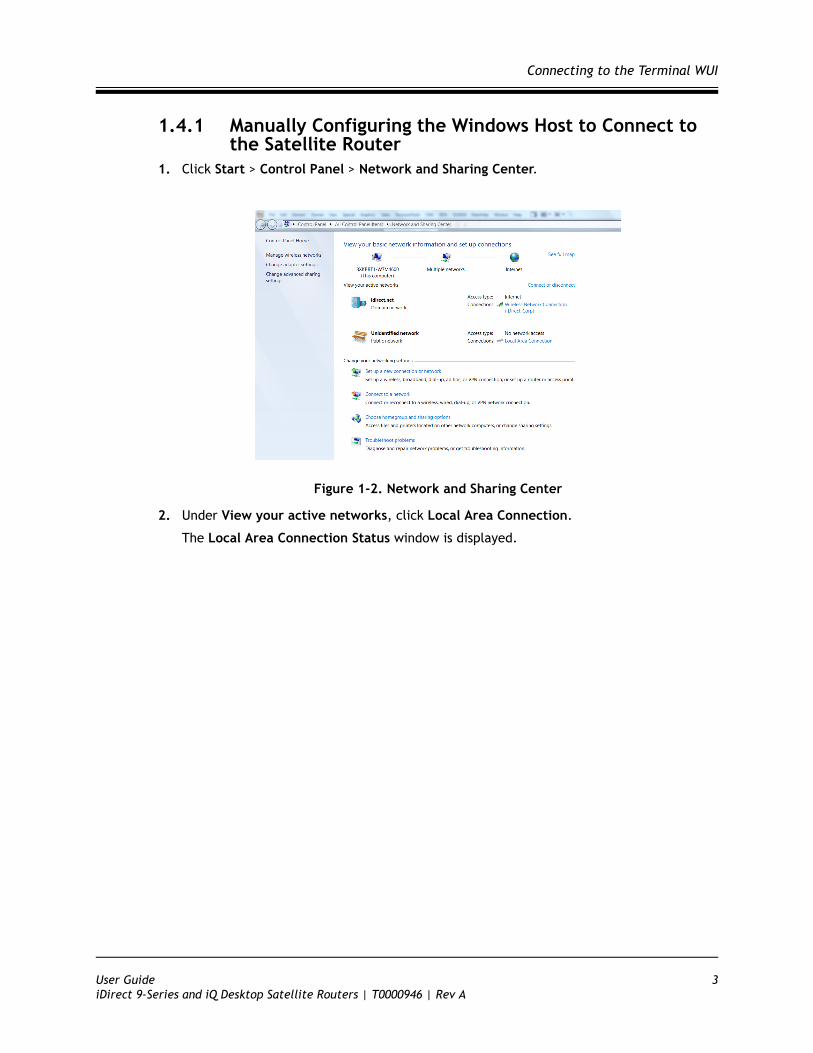
1.4.1 Manually Configuring the Windows Host to Connect to the Satellite Router
1. Click Start > Control Panel > Network and Sharing Center.
Figure 1-2. Network and Sharing Center
2. Under View your active networks, click Local Area Connection.
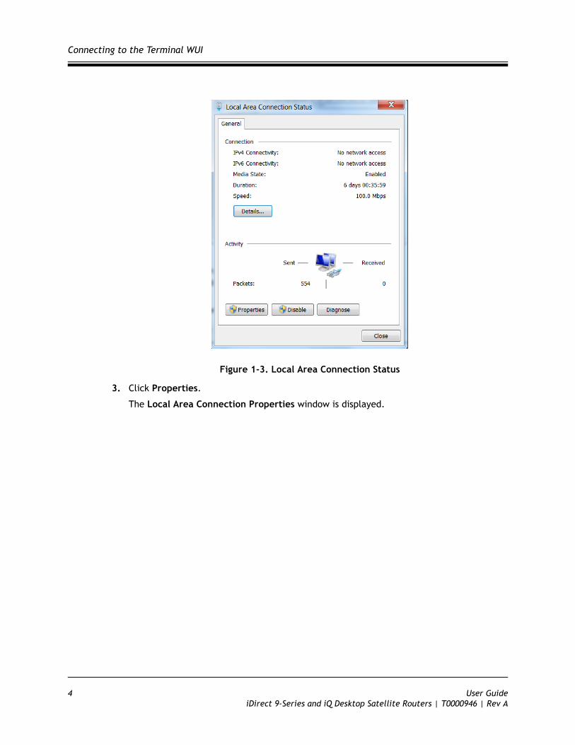
The Local Area Connection Status window is displayed.
User Guide 3iDirect 9-Series and iQ Desktop Satellite Routers | T0000946 | Rev A
Connecting to the Terminal WUI
Figure 1-3. Local Area Connection Status
3. Click Properties.
The Local Area Connection Properties window is displayed.
4 User GuideiDirect 9-Series and iQ Desktop Satellite Routers | T0000946 | Rev A
Connecting to the Terminal WUI
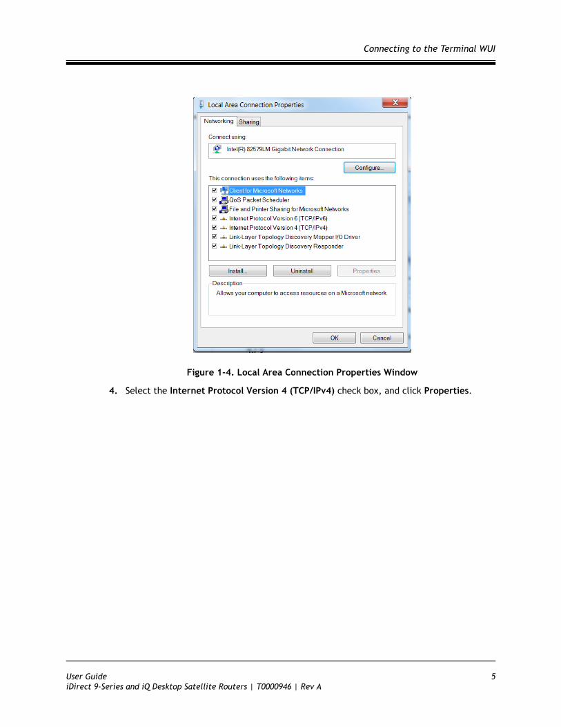
Figure 1-4. Local Area Connection Properties Window
4. Select the Internet Protocol Version 4 (TCP/IPv4) check box, and click Properties.
User Guide 5iDirect 9-Series and iQ Desktop Satellite Routers | T0000946 | Rev A
Starting a Terminal WUI Session
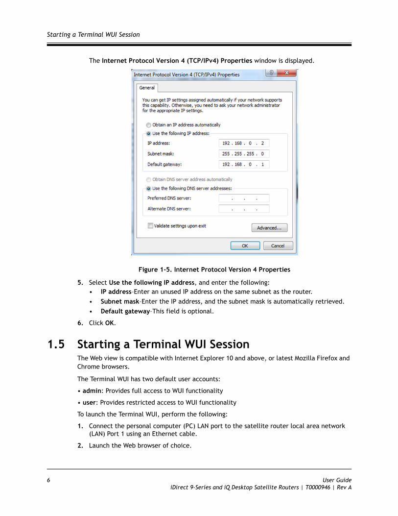
The Internet Protocol Version 4 (TCP/IPv4) Properties window is displayed.
Figure 1-5. Internet Protocol Version 4 Properties
5. Select Use the following IP address, and enter the following:• IP address–Enter an unused IP address on the same subnet as the router.
• Subnet mask–Enter the IP address, and the subnet mask is automatically retrieved.
• Default gateway–This field is optional.
6. Click OK.
1.5 Starting a Terminal WUI SessionThe Web view is compatible with Internet Explorer 10 and above, or latest Mozilla Firefox and Chrome browsers.
The Terminal WUI has two default user accounts:
• admin: Provides full access to WUI functionality
• user: Provides restricted access to WUI functionality
To launch the Terminal WUI, perform the following:
1. Connect the personal computer (PC) LAN port to the satellite router local area network (LAN) Port 1 using an Ethernet cable.
2. Launch the Web browser of choice.
6 User GuideiDirect 9-Series and iQ Desktop Satellite Routers | T0000946 | Rev A
Starting a Terminal WUI Session
On the address bar, enter the IP address of the satellite router into the address field.
The login terminal as seen in Figure 1-1 is displayed.
3. Enter the Username and Password as follows:
Username - admin
Password - iDirect
4. Click Login.
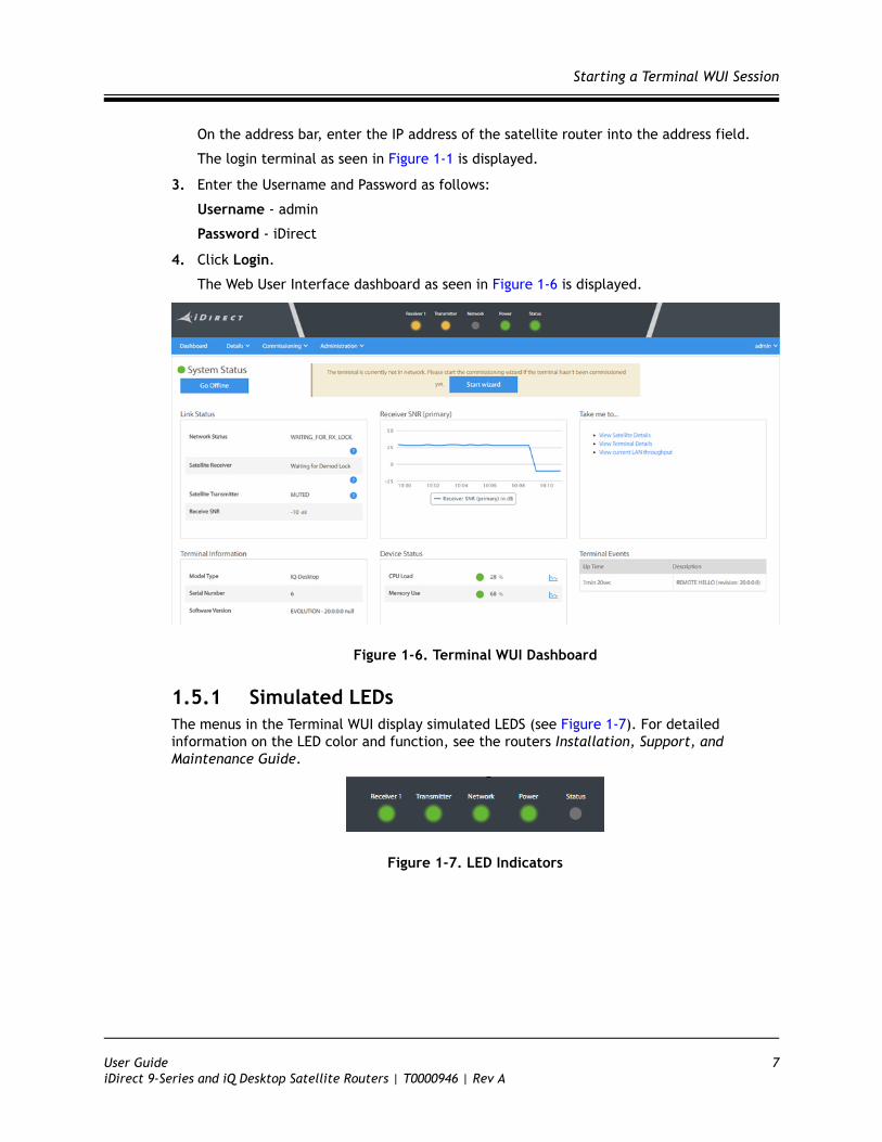
The Web User Interface dashboard as seen in Figure 1-6 is displayed.
Figure 1-6. Terminal WUI Dashboard
1.5.1 Simulated LEDsThe menus in the Terminal WUI display simulated LEDS (see Figure 1-7). For detailed information on the LED color and function, see the routers Installation, Support, and Maintenance Guide.
Figure 1-7. LED Indicators
User Guide 7iDirect 9-Series and iQ Desktop Satellite Routers | T0000946 | Rev A

Starting a Terminal WUI Session
8 User GuideiDirect 9-Series and iQ Desktop Satellite Routers | T0000946 | Rev A

2 Terminal Web User Interface
This chapter introduces the Terminal Web User Interface (WUI) provided on iDirect Satellite Routers. It contains the following sections:
• Section 2.1, Dashboard on page 9
• Section 2.2, Details Menu on page 11
• Section 2.3, Administration on page 19
• Section 2.4, Commissioning on page 21
2.1 DashboardThe Dashboard page provides key information about the Satellite Routers that have an established connection.
The Dashboard page is the default landing page of the Terminal Web UI. See Figure 2-1.
Figure 2-1. Dashboard Menu
User Guide 9iDirect 9-Series and iQ Desktop Satellite Routers | T0000946 | Rev A
Dashboard
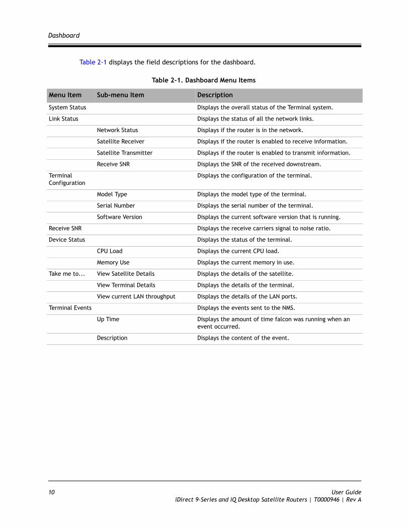
Table 2-1 displays the field descriptions for the dashboard.
Table 2-1. Dashboard Menu Items
Menu Item Sub-menu Item Description
System Status Displays the overall status of the Terminal system.
Link Status Displays the status of all the network links.
Network Status Displays if the router is in the network.
Satellite Receiver Displays if the router is enabled to receive information.
Satellite Transmitter Displays if the router is enabled to transmit information.
Receive SNR Displays the SNR of the received downstream.
Terminal Configuration
Displays the configuration of the terminal.
Model Type Displays the model type of the terminal.
Serial Number Displays the serial number of the terminal.
Software Version Displays the current software version that is running.
Receive SNR Displays the receive carriers signal to noise ratio.
Device Status Displays the status of the terminal.
CPU Load Displays the current CPU load.
Memory Use Displays the current memory in use.
Take me to... View Satellite Details Displays the details of the satellite.
View Terminal Details Displays the details of the terminal.
View current LAN throughput Displays the details of the LAN ports.
Terminal Events Displays the events sent to the NMS.
Up Time Displays the amount of time falcon was running when an event occurred.
Description Displays the content of the event.
10 User GuideiDirect 9-Series and iQ Desktop Satellite Routers | T0000946 | Rev A
Details Menu
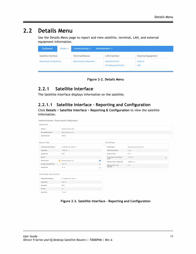
2.2 Details MenuUse the Details Menu page to report and view satellite, terminal, LAN, and external equipment information.
Figure 2-2. Details Menu
2.2.1 Satellite InterfaceThe Satellite Interface displays information on the satellite.
2.2.1.1 Satellite Interface - Reporting and ConfigurationClick Details > Satellite Interface > Reporting & Configuration to view the satellite information.
Figure 2-3. Satellite Interface - Reporting and Configuration
User Guide 11iDirect 9-Series and iQ Desktop Satellite Routers | T0000946 | Rev A

Details Menu
Table 2-2 displays the field descriptions for the satellite interface.
Table 2-2. Satellite Interface - Reporting and Configuration Field Descriptions
Menu Item Sub-menu Item Sub-menu Item Description
Satellite Interface- Reporting and Configuration
Modem State Displays the status of the modem.
Network Displays if the modem is connected to the network.
Main Satellite Receive Displays one of the following:
• Locked• Waiting for NCR Lock—Third and final
stage of the receiver lock.• Waiting for Demod Lock—Second stage
of the receiver lock.• Waiting for Tuner
Locktuner_locked—First stage of the receiver lock.
• Off
Satellite Transmit Displays the state as either MUTED or UNMUTED. The transmitter can be muted by any of the following conditions:
• not in network• external mute signal• OpenAMIP mute commandNOTE: The above conditions are not
exhaustive.
Transmit State Displays the status of the transmitter.
Point of Report Indicates the point for which the terminal's transmit power is reported. This point could be either at the output of the satellite router's transmit output, or at the BUC flange.
Initial Transmit Power Displays the initial transmit power of the satellite router.
Maximum Power Displays the configured max power of the satellite router’s transmitter.
Power Relative to the Nominal Carrier
Displays the current transmit power relative to the nominal carrier.
Reference Carrier - Symbol Rate
Displays the symbol rate of the reference carrier.
Reference Carrier - C/N threshold
Displays the threshold of the reference carrier.
12 User GuideiDirect 9-Series and iQ Desktop Satellite Routers | T0000946 | Rev A
Details Menu
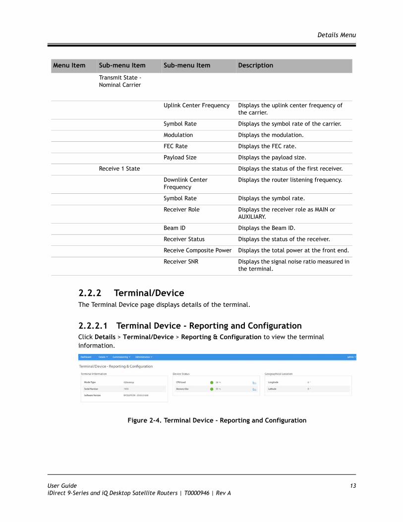
2.2.2 Terminal/DeviceThe Terminal Device page displays details of the terminal.
2.2.2.1 Terminal Device - Reporting and ConfigurationClick Details > Terminal/Device > Reporting & Configuration to view the terminal information.
Figure 2-4. Terminal Device - Reporting and Configuration
Transmit State - Nominal Carrier
Uplink Center Frequency Displays the uplink center frequency of the carrier.
Symbol Rate Displays the symbol rate of the carrier.
Modulation Displays the modulation.
FEC Rate Displays the FEC rate.
Payload Size Displays the payload size.
Receive 1 State Displays the status of the first receiver.
Downlink Center Frequency
Displays the router listening frequency.
Symbol Rate Displays the symbol rate.
Receiver Role Displays the receiver role as MAIN or AUXILIARY.
Beam ID Displays the Beam ID.
Receiver Status Displays the status of the receiver.
Receive Composite Power Displays the total power at the front end.
Receiver SNR Displays the signal noise ratio measured in the terminal.
Menu Item Sub-menu Item Sub-menu Item Description
User Guide 13iDirect 9-Series and iQ Desktop Satellite Routers | T0000946 | Rev A
Details Menu
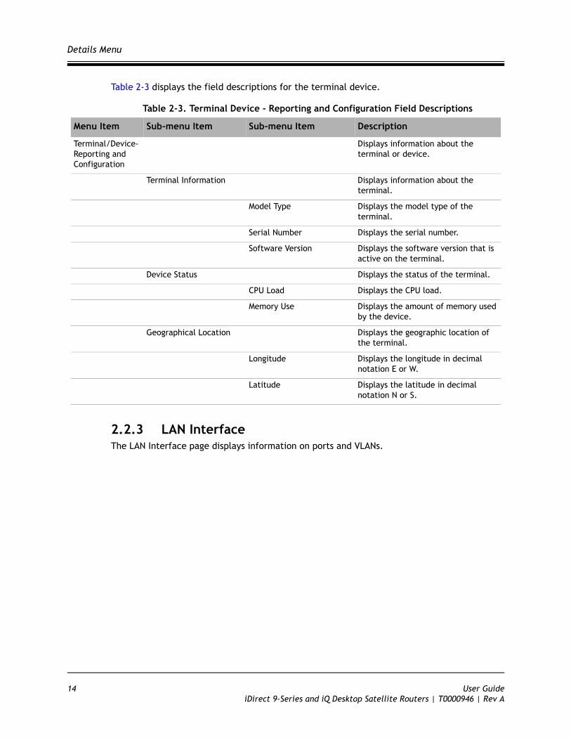
Table 2-3 displays the field descriptions for the terminal device.
Table 2-3. Terminal Device - Reporting and Configuration Field Descriptions
2.2.3 LAN InterfaceThe LAN Interface page displays information on ports and VLANs.
Menu Item Sub-menu Item Sub-menu Item Description
Terminal/Device- Reporting and Configuration
Displays information about the terminal or device.
Terminal Information Displays information about the terminal.
Model Type Displays the model type of the terminal.
Serial Number Displays the serial number.
Software Version Displays the software version that is active on the terminal.
Device Status Displays the status of the terminal.
CPU Load Displays the CPU load.
Memory Use Displays the amount of memory used by the device.
Geographical Location Displays the geographic location of the terminal.
Longitude Displays the longitude in decimal notation E or W.
Latitude Displays the latitude in decimal notation N or S.
14 User GuideiDirect 9-Series and iQ Desktop Satellite Routers | T0000946 | Rev A
Details Menu
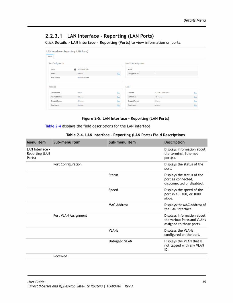
2.2.3.1 LAN Interface - Reporting (LAN Ports)Click Details > LAN Interface > Reporting (Ports) to view information on ports.
Figure 2-5. LAN Interface - Reporting (LAN Ports)
Table 2-4 displays the field descriptions for the LAN interface.
Table 2-4. LAN Interface - Reporting (LAN Ports) Field Descriptions
Menu Item Sub-menu Item Sub-menu Item Description
LAN Interface - Reporting (LAN Ports)
Displays information about the terminal Ethernet port(s).
Port Configuration Displays the status of the port.
Status Displays the status of the port as connected, disconnected or disabled.
Speed Displays the speed of the port in 10, 100, or 1000 Mbps.
MAC Address Displays the MAC address of the LAN interface.
Port VLAN Assignment Displays information about the various Ports and VLANs assigned to those ports.
VLANs Displays the VLANs configured on the port.
Untagged VLAN Displays the VLAN that is not tagged with any VLAN ID.
Received
User Guide 15iDirect 9-Series and iQ Desktop Satellite Routers | T0000946 | Rev A
Details Menu
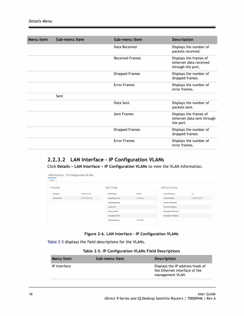
2.2.3.2 LAN Interface - IP Configuration VLANsClick Details > LAN Interface > IP Configuration VLANs to view the VLAN information.
Figure 2-6. LAN Interface - IP Configuration VLANs
Table 2-5 displays the field descriptions for the VLANs.
Table 2-5. IP Configuration VLANs Field Descriptions
Data Received Displays the number of packets received.
Received Frames Displays the frames of ethernet data received through the port.
Dropped Frames Displays the number of dropped frames.
Error Frames Displays the number of error frames.
Sent
Data Sent Displays the number of packets sent.
Sent Frames Displays the frames of ethernet data sent through the port.
Dropped Frames Displays the number of dropped frames.
Error Frames Displays the number of error frames.
Menu Item Sub-menu Item Sub-menu Item Description
Menu Item Sub-menu Item Description
IP Interface Displays the IP address/mask of the Ethernet interface of the management VLAN.
16 User GuideiDirect 9-Series and iQ Desktop Satellite Routers | T0000946 | Rev A
Details Menu
2.2.4 External EquipmentThe External Equipment page displays information on the BUC, LNB, and Antenna.
2.2.4.1 External Equipment - Antenna
Figure 2-7. External Equipment - Antenna
IP Address Displays the IP address.
Subnet Mask Displays the subnet mask address.
DHCP Config Displays the DHCP configuration information.
DHCP Mode Displays the DHCP mode as either Server, Client, or Relay.
Lease Range Start Displays the DHCP servers lease range start.
Lease Range End Displays the DHCP servers lease range end.
Lease Time Displays the DHCP servers lease time.
Primary DHCP Displays the primary DHCP server.
Secondary DHCP Displays the secondary DHCP server.
Default Gateway Displays the default gateway.
DNS Config
Local DNS Name Displays the local DNS name.
Local IP Address Displays the local IP address.
Primary DNS Name Displays the DNS server name.
Primary IP Address Displays the primary DNS server IP address.
Secondary DNS Name Displays the DNS secondary name.
Secondary IP Address Displays the secondary DNS server IP address.
Menu Item Sub-menu Item Description
User Guide 17iDirect 9-Series and iQ Desktop Satellite Routers | T0000946 | Rev A

Details Menu
2.2.4.2 External Equipment - LNBClick Details > External Equipment > LNB to view the LNB information.
Figure 2-8. External Equipment - LNB
Table 2-6 displays the field descriptions for the LNB.
Table 2-6. LNB Field Descriptions
Menu Item Sub-menu Item Sub-menu Item Description
External Equipment -LNB
LNB Information Displays LNB information.
Translation Displays the LNBs LO frequency.
Spectral Inversion Displays the value as True or False if enabled in the options file. This is the function of the BUC or LNB where it mirror images the signal that helps in decoding the signal.
Reference Displays the LNB's reference clock in MHz.
18 User GuideiDirect 9-Series and iQ Desktop Satellite Routers | T0000946 | Rev A
Administration
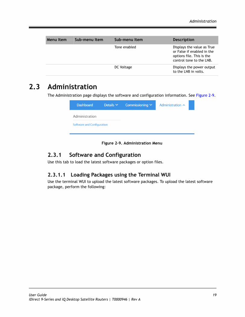
2.3 AdministrationThe Administration page displays the software and configuration information. See Figure 2-9.
Figure 2-9. Administration Menu
2.3.1 Software and ConfigurationUse this tab to load the latest software packages or option files.
2.3.1.1 Loading Packages using the Terminal WUIUse the terminal WUI to upload the latest software packages. To upload the latest software package, perform the following:
Tone enabled Displays the value as True or False if enabled in the options file. This is the control tone to the LNB.
DC Voltage Displays the power output to the LNB in volts.
Menu Item Sub-menu Item Sub-menu Item Description
User Guide 19iDirect 9-Series and iQ Desktop Satellite Routers | T0000946 | Rev A
Administration
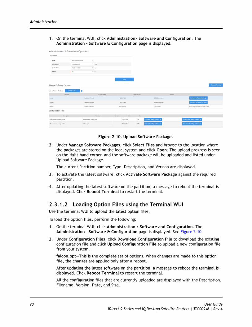
1. On the terminal WUI, click Administration> Software and Configuration. The Administration - Software & Configuration page is displayed.
Figure 2-10. Upload Software Packages
2. Under Manage Software Packages, click Select Files and browse to the location where the packages are stored on the local system and click Open. The upload progress is seen on the right-hand corner. and the software package will be uploaded and listed under Upload Software Package.
The current Partition number, Type, Description, and Version are displayed.
3. To activate the latest software, click Activate Software Package against the required partition.
4. After updating the latest software on the partition, a message to reboot the terminal is displayed. Click Reboot Terminal to restart the terminal.
2.3.1.2 Loading Option Files using the Terminal WUIUse the terminal WUI to upload the latest option files.
To load the option files, perform the following:
1. On the terminal WUI, click Administration > Software and Configuration. The Administration - Software & Configuration page is displayed. See Figure 2-10.
2. Under Configuration Files, click Download Configuration File to download the existing configuration file and click Upload Configuration File to upload a new configuration file from your system.
falcon.opt—This is the complete set of options. When changes are made to this option file, the changes are applied only after a reboot.
After updating the latest software on the partition, a message to reboot the terminal is displayed. Click Reboot Terminal to restart the terminal.
All the configuration files that are currently uploaded are displayed with the Description, Filename, Version, Date, and Size.
20 User GuideiDirect 9-Series and iQ Desktop Satellite Routers | T0000946 | Rev A
Commissioning
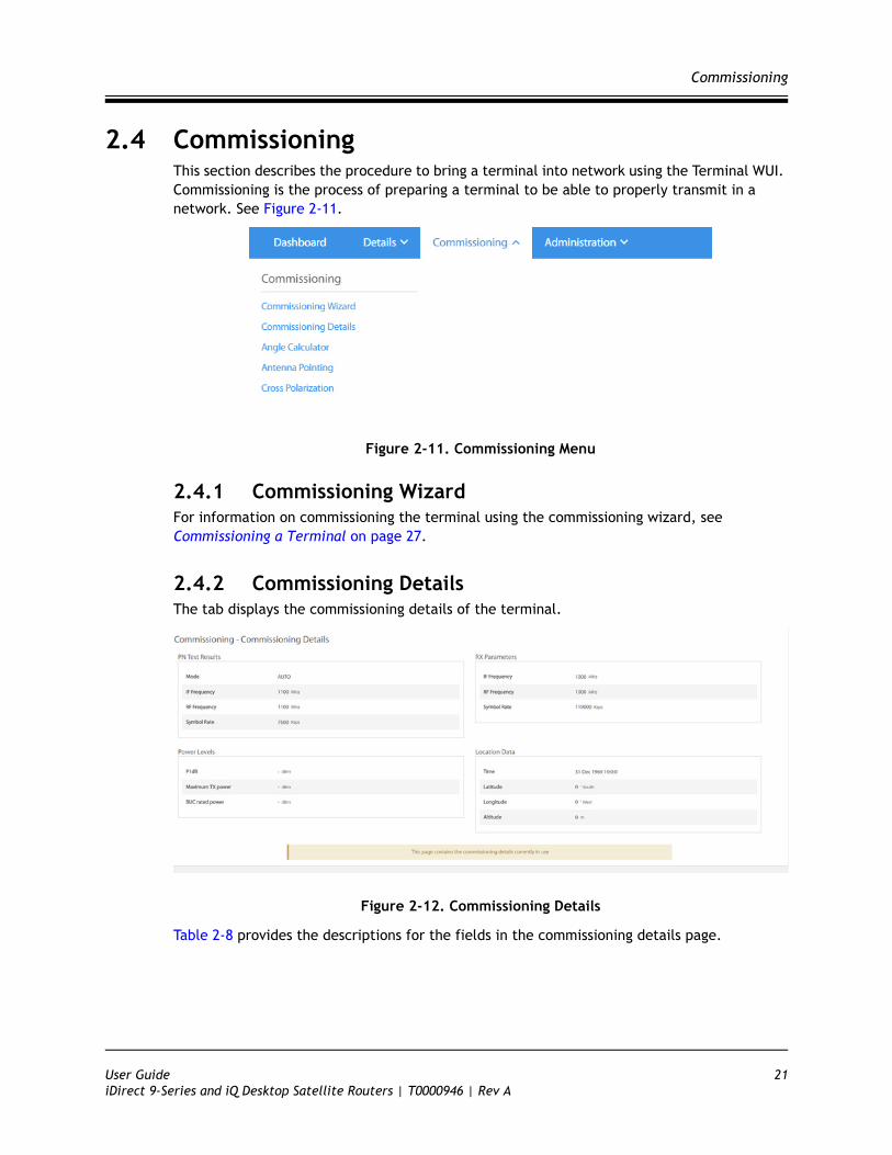
2.4 CommissioningThis section describes the procedure to bring a terminal into network using the Terminal WUI. Commissioning is the process of preparing a terminal to be able to properly transmit in a network. See Figure 2-11.
Figure 2-11. Commissioning Menu
2.4.1 Commissioning WizardFor information on commissioning the terminal using the commissioning wizard, see Commissioning a Terminal on page 27.
2.4.2 Commissioning DetailsThe tab displays the commissioning details of the terminal.
Figure 2-12. Commissioning Details
Table 2-8 provides the descriptions for the fields in the commissioning details page.
User Guide 21iDirect 9-Series and iQ Desktop Satellite Routers | T0000946 | Rev A
Commissioning
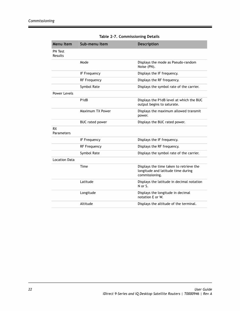
Table 2-7. Commissioning Details
Menu Item Sub-menu Item Description
PN Test Results
Mode Displays the mode as Pseudo-random Noise (PN).
IF Frequency Displays the IF frequency.
RF Frequency Displays the RF frequency.
Symbol Rate Displays the symbol rate of the carrier.
Power Levels
P1dB Displays the P1dB level at which the BUC output begins to saturate.
Maximum TX Power Displays the maximum allowed transmit power.
BUC rated power Displays the BUC rated power.
RX Parameters
IF Frequency Displays the IF frequency.
RF Frequency Displays the RF frequency.
Symbol Rate Displays the symbol rate of the carrier.
Location Data
Time Displays the time taken to retrieve the longitude and latitude time during commissioning.
Latitude Displays the latitude in decimal notation N or S.
Longitude Displays the longitude in decimal notation E or W.
Altitude Displays the altitude of the terminal.
22 User GuideiDirect 9-Series and iQ Desktop Satellite Routers | T0000946 | Rev A
Commissioning
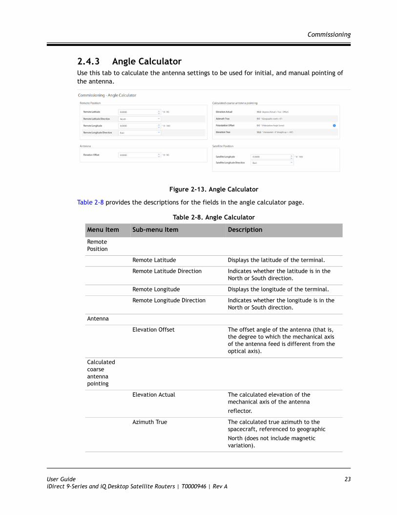
2.4.3 Angle CalculatorUse this tab to calculate the antenna settings to be used for initial, and manual pointing of the antenna.
Figure 2-13. Angle Calculator
Table 2-8 provides the descriptions for the fields in the angle calculator page.
Table 2-8. Angle Calculator
Menu Item Sub-menu Item Description
Remote Position
Remote Latitude Displays the latitude of the terminal.
Remote Latitude Direction Indicates whether the latitude is in the North or South direction.
Remote Longitude Displays the longitude of the terminal.
Remote Longitude Direction Indicates whether the longitude is in the North or South direction.
Antenna
Elevation Offset The offset angle of the antenna (that is, the degree to which the mechanical axis of the antenna feed is different from the optical axis).
Calculated coarse antenna pointing
Elevation Actual The calculated elevation of the mechanical axis of the antenna
reflector.
Azimuth True The calculated true azimuth to the spacecraft, referenced to geographic
North (does not include magnetic variation).
User Guide 23iDirect 9-Series and iQ Desktop Satellite Routers | T0000946 | Rev A
Commissioning
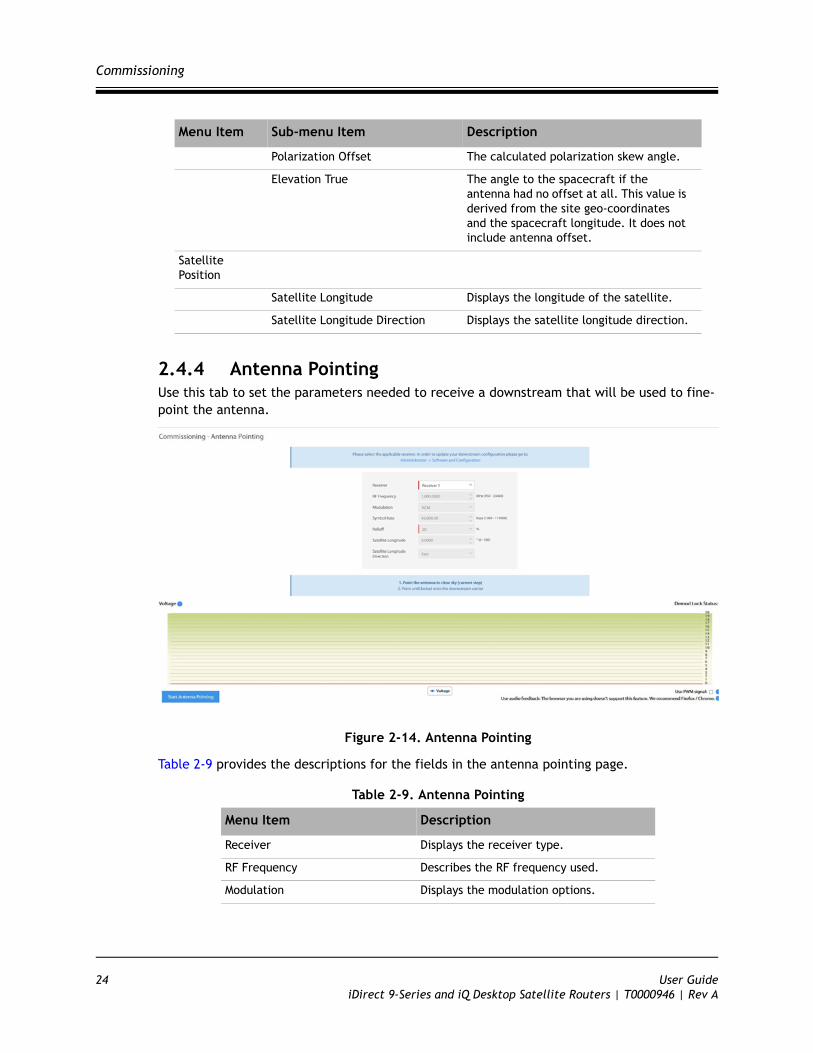
2.4.4 Antenna PointingUse this tab to set the parameters needed to receive a downstream that will be used to fine-point the antenna.
Figure 2-14. Antenna Pointing
Table 2-9 provides the descriptions for the fields in the antenna pointing page.
Table 2-9. Antenna Pointing
Polarization Offset The calculated polarization skew angle.
Elevation True The angle to the spacecraft if the antenna had no offset at all. This value is derived from the site geo-coordinates and the spacecraft longitude. It does not include antenna offset.
Satellite Position
Satellite Longitude Displays the longitude of the satellite.
Satellite Longitude Direction Displays the satellite longitude direction.
Menu Item Description
Receiver Displays the receiver type.
RF Frequency Describes the RF frequency used.
Modulation Displays the modulation options.
Menu Item Sub-menu Item Description
24 User GuideiDirect 9-Series and iQ Desktop Satellite Routers | T0000946 | Rev A
Commissioning
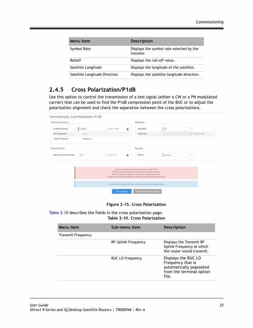
2.4.5 Cross Polarization/P1dBUse this option to control the transmission of a test signal (either a CW or a PN modulated carrier) that can be used to find the P1dB compression point of the BUC or to adjust the polarization alignment and check the separation between the cross polarizations.
Figure 2-15. Cross Polarization
Table 2-10 describes the fields in the cross polarization page.
Symbol Rate Displays the symbol rate selected by the installer.
Rolloff Displays the roll-off value.
Satellite Longitude Displays the longitude of the satellite.
Satellite Longitude Direction Displays the satellite longitude direction.
Table 2-10. Cross Polarization
Menu Item Sub-menu Item Description
Transmit Frequency
RF Uplink Frequency Displays the Transmit RF Uplink Frequency at which the router would transmit.
BUC LO Frequency Displays the BUC LO Frequency that is automatically populated from the terminal option file.
Menu Item Description
User Guide 25iDirect 9-Series and iQ Desktop Satellite Routers | T0000946 | Rev A
Commissioning
L-Band Tx Frequency Displays the L-Band Tx Frequency that is calculated based on the RF uplink frequency and BUC LO frequency.
Transmit Power
Adjust L-Band Transmit Power Displays the power value set by the installer.
Modulator
Modulation Displays the modulation options.
Symbol Rate Displays the symbol rate selected by the installer.
Receiver Displays the receiver type.
Table 2-10. Cross Polarization
Menu Item Sub-menu Item Description
26 User GuideiDirect 9-Series and iQ Desktop Satellite Routers | T0000946 | Rev A

Introduction
3 Commissioning a Terminal
This chapter describes how to commission a satellite router. Commissioning is the process of preparing a satellite router to be able to properly transmit in a network.
This chapter includes the following sections:
• Section 3.1, Introduction on page 27
• Section 3.2, Software Upgrade on page 28
• Section 3.3, Manual Antenna Pointing (without OpenAMIP) on page 28
• Section 3.4, Cross-Polarization Test on page 33
3.1 IntroductionCommissioning is the process of preparing a terminal to be able to properly transmit in a network.
To commission a remote using the Terminal WUI, click Commissioning > Commissioning Wizard. See Figure 3-1.
Figure 3-1. Commissioning Menu
NOTE: For commissioning a remote with manual antenna, see Manual Antenna Pointing (without OpenAMIP) on page 28. For commissioning a remote with automatic antennas, see Cross-Polarization Test on page 33.
User Guide 27iDirect 9-Series and iQ Desktop Satellite Routers | T0000946 | Rev A
Software Upgrade
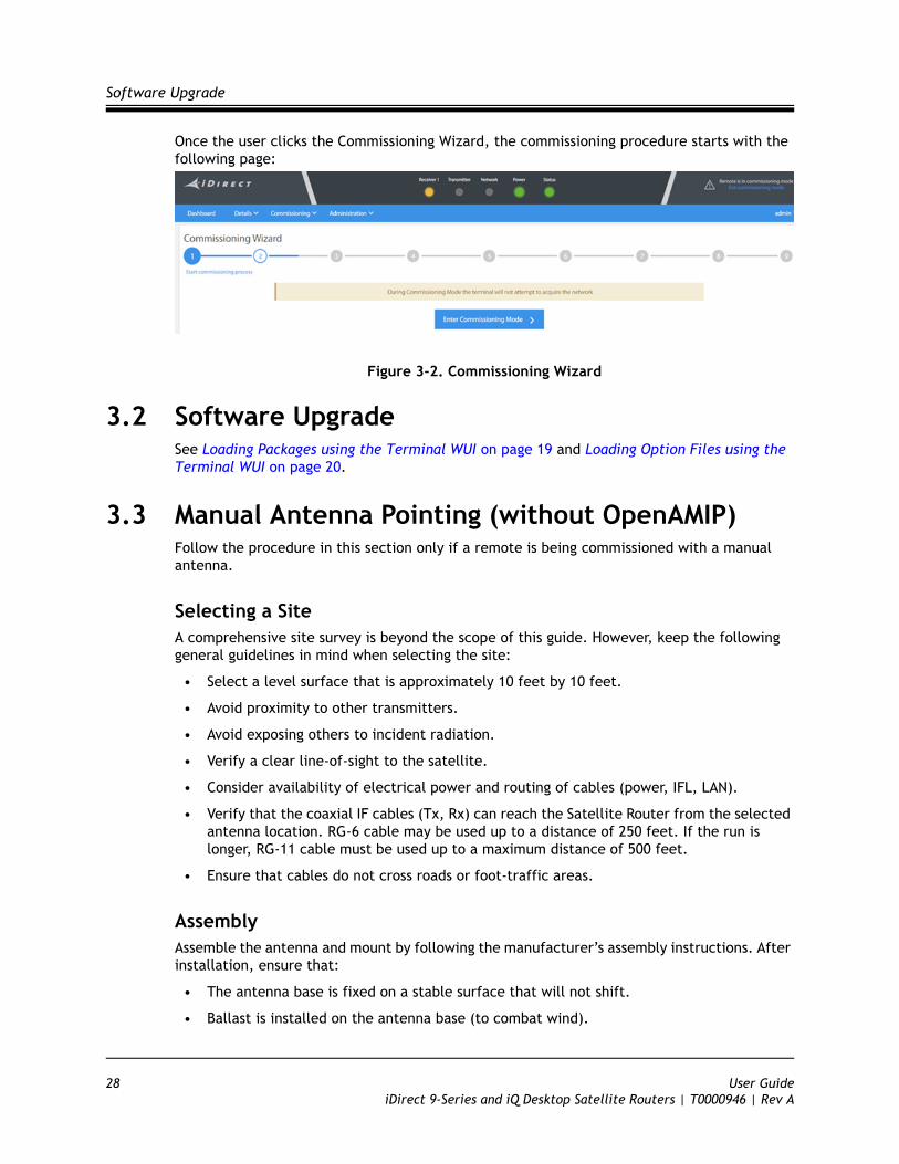
Once the user clicks the Commissioning Wizard, the commissioning procedure starts with the following page:
Figure 3-2. Commissioning Wizard
3.2 Software UpgradeSee Loading Packages using the Terminal WUI on page 19 and Loading Option Files using the Terminal WUI on page 20.
3.3 Manual Antenna Pointing (without OpenAMIP)Follow the procedure in this section only if a remote is being commissioned with a manual antenna.
Selecting a SiteA comprehensive site survey is beyond the scope of this guide. However, keep the following general guidelines in mind when selecting the site:
• Select a level surface that is approximately 10 feet by 10 feet.
• Avoid proximity to other transmitters.
• Avoid exposing others to incident radiation.
• Verify a clear line-of-sight to the satellite.
• Consider availability of electrical power and routing of cables (power, IFL, LAN).
• Verify that the coaxial IF cables (Tx, Rx) can reach the Satellite Router from the selected antenna location. RG-6 cable may be used up to a distance of 250 feet. If the run is longer, RG-11 cable must be used up to a maximum distance of 500 feet.
• Ensure that cables do not cross roads or foot-traffic areas.
AssemblyAssemble the antenna and mount by following the manufacturer’s assembly instructions. After installation, ensure that:
• The antenna base is fixed on a stable surface that will not shift.
• Ballast is installed on the antenna base (to combat wind).
28 User GuideiDirect 9-Series and iQ Desktop Satellite Routers | T0000946 | Rev A

Manual Antenna Pointing (without OpenAMIP)
• The mast pipe is plumb.
OrientationThe following section describes antenna orientation principles generally applicable to all site installations, illustrated with a typical VSAT antenna configuration. Magnetic variation and elevation offset principles are discussed in detail.
Magnetic VariationMagnetic variation (also referred to as “declination”) is the difference between the true heading referenced to the geographic North Pole, and the magnetic heading as registered on a magnetic compass. The magnitude and direction of magnetic variation differs depending upon the geographic location. Magnetic variation changes slowly with time.
Figure 3-3 illustrates magnetic variation in the United States. More detailed, up-to-date maps are available on the Internet, and must be consulted for the latest data.
Figure 3-3. Example: Magnetic Declination
Magnetic variation alters the reading of a magnetic compass with respect to true North. Maps and map display systems, including the output of the iDirect Look Angle Calculator, are referenced to true geographic North. Therefore a correction factor must be applied to
NOTE: The antenna may not be identical to the antenna used in this example. See the antenna manufacturer’s instructions for specific information.
User Guide 29iDirect 9-Series and iQ Desktop Satellite Routers | T0000946 | Rev A
Manual Antenna Pointing (without OpenAMIP)
readings taken by a magnetic compass to obtain the correct value, referred to as the true heading.
Magnetic variation is specified in degrees East or West of the agonic line (line of zero variation), shown as a red dotted line in Figure 3-3. As depicted in the figure, East declination causes the compass to be deflected to the right of the true heading, while West declination causes the compass needle to deflect to the left of the true heading. Consequently, add West declination, and subtract East declination, from the compass reading to obtain the true heading.
For example, the illustration depicts the 10 West isogonic line passing through Baltimore, MD. In that location, 10 degrees must be added to the compass indication to obtain the true heading.
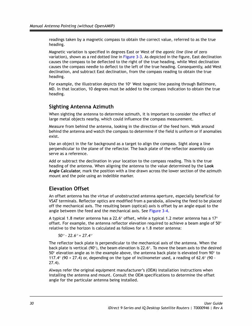
Sighting Antenna AzimuthWhen sighting the antenna to determine azimuth, it is important to consider the effect of large metal objects nearby, which could influence the compass measurement.
Measure from behind the antenna, looking in the direction of the feed horn. Walk around behind the antenna and watch the compass to determine if the field is uniform or if anomalies exist.
Use an object in the far background as a target to align the compass. Sight along a line perpendicular to the plane of the reflector. The back plate of the reflector assembly can serve as a reference.
Add or subtract the declination in your location to the compass reading. This is the true heading of the antenna. When aligning the antenna to the value determined by the Look Angle Calculator, mark the position with a line drawn across the lower section of the azimuth mount and the pole using an indelible marker.
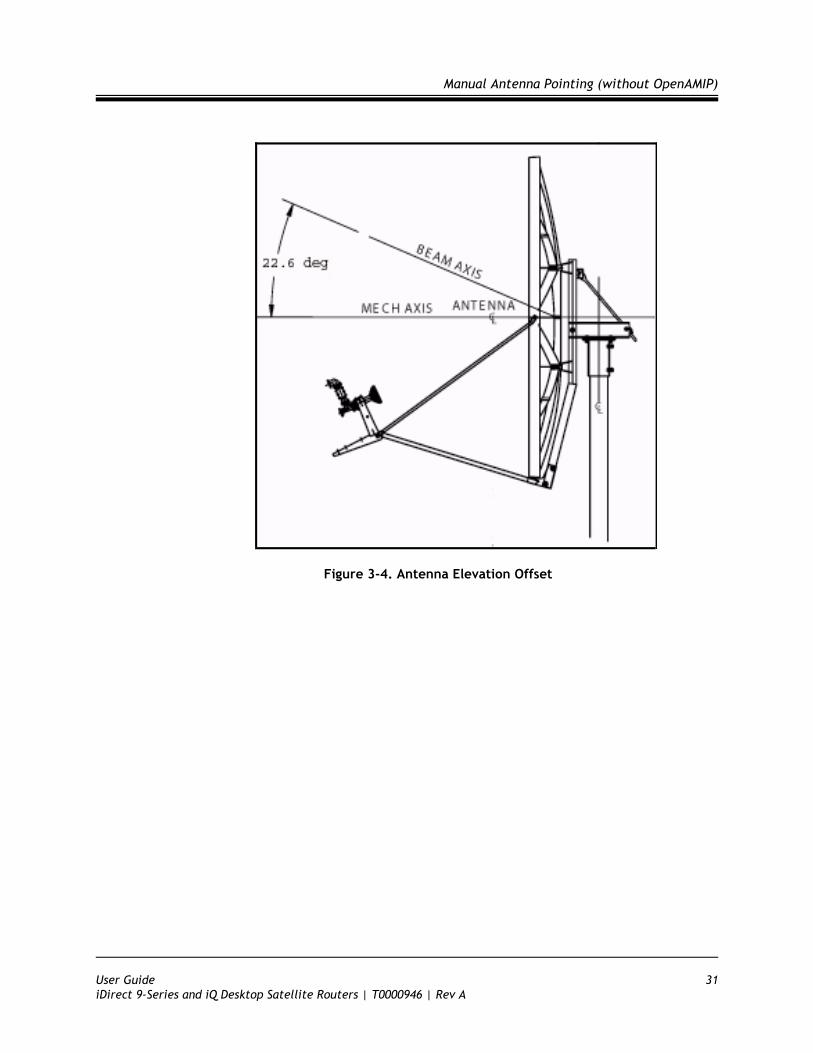
Elevation OffsetAn offset antenna has the virtue of unobstructed antenna aperture, especially beneficial for VSAT terminals. Reflector optics are modified from a parabola, allowing the feed to be placed off the mechanical axis. The resulting beam (optical) axis is offset by an angle equal to the angle between the feed and the mechanical axis. See Figure 3-4.
A typical 1.8 meter antenna has a 22.6 offset, while a typical 1.2 meter antenna has a 17 offset. For example, the antenna reflector elevation required to achieve a beam angle of 50relative to the horizon is calculated as follows for a 1.8 meter antenna:
50 - 22.6 = 27.4
The reflector back plate is perpendicular to the mechanical axis of the antenna. When the back plate is vertical (90, the beam elevation is 22.6. To move the beam axis to the desired 50 elevation angle as in the example above, the antenna back plate is elevated from 90 to 117.4 (90 + 27.4) or, depending on the type of inclinometer used, a reading of 62.6(90 - 27.4).
Always refer the original equipment manufacturer’s (OEM) installation instructions when installing the antenna and mount. Consult the OEM specifications to determine the offset angle for the particular antenna being installed.
30 User GuideiDirect 9-Series and iQ Desktop Satellite Routers | T0000946 | Rev A
Manual Antenna Pointing (without OpenAMIP)
Figure 3-4. Antenna Elevation Offset
User Guide 31iDirect 9-Series and iQ Desktop Satellite Routers | T0000946 | Rev A
Manual Antenna Pointing (without OpenAMIP)
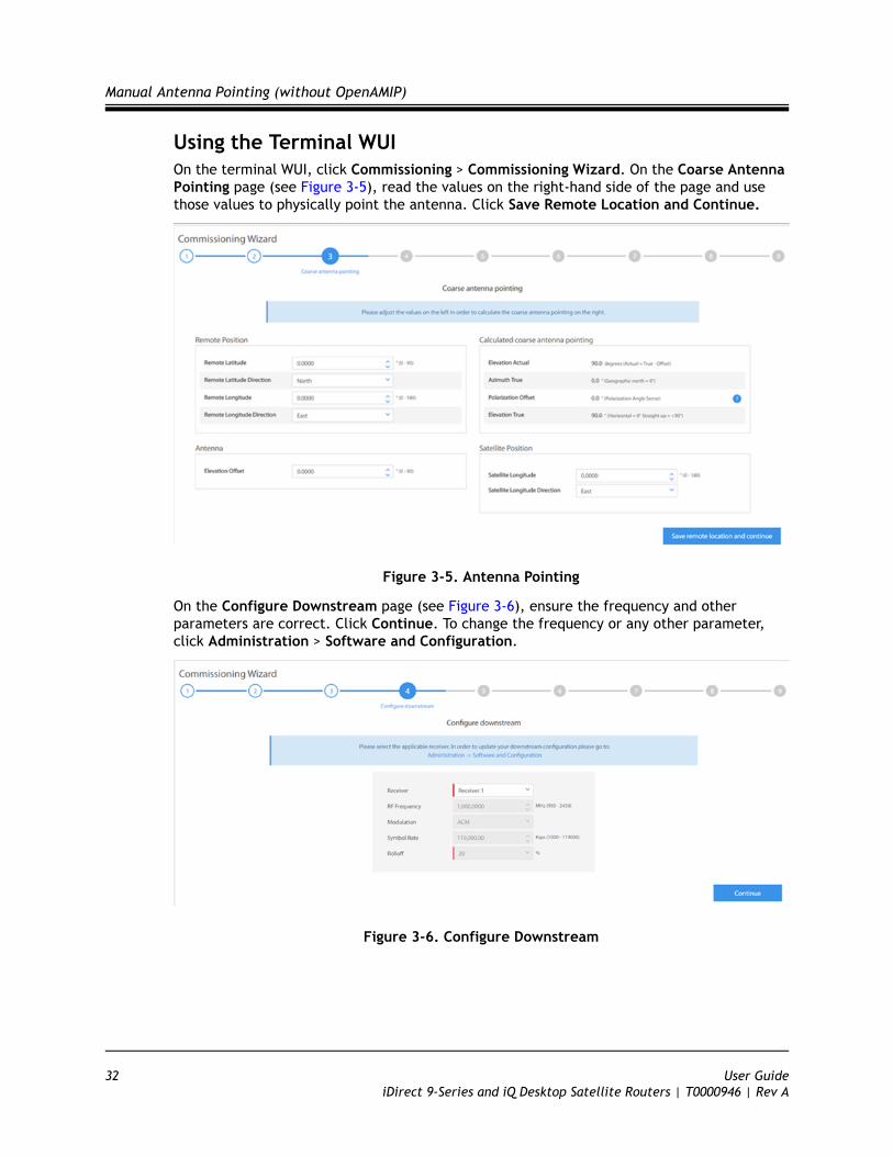
Using the Terminal WUIOn the terminal WUI, click Commissioning > Commissioning Wizard. On the Coarse Antenna Pointing page (see Figure 3-5), read the values on the right-hand side of the page and use those values to physically point the antenna. Click Save Remote Location and Continue.
Figure 3-5. Antenna Pointing
On the Configure Downstream page (see Figure 3-6), ensure the frequency and other parameters are correct. Click Continue. To change the frequency or any other parameter, click Administration > Software and Configuration.
Figure 3-6. Configure Downstream
32 User GuideiDirect 9-Series and iQ Desktop Satellite Routers | T0000946 | Rev A
Cross-Polarization Test
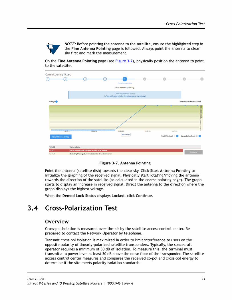
On the Fine Antenna Pointing page (see Figure 3-7), physically position the antenna to point to the satellite.
Figure 3-7. Antenna Pointing
Point the antenna (satellite dish) towards the clear sky. Click Start Antenna Pointing to initialize the graphing of the received signal. Physically start rotating/moving the antenna towards the direction of the satellite (as calculated in the coarse pointing page). The graph starts to display an increase in received signal. Direct the antenna to the direction where the graph displays the highest voltage.
When the Demod Lock Status displays Locked, click Continue.
3.4 Cross-Polarization Test
OverviewCross-pol isolation is measured over-the-air by the satellite access control center. Be prepared to contact the Network Operator by telephone.
Transmit cross-pol isolation is maximized in order to limit interference to users on the opposite polarity of linearly-polarized satellite transponders. Typically, the spacecraft operator requires a minimum of 30 dB of isolation. To measure this, the terminal must transmit at a power level at least 30 dB above the noise floor of the transponder. The satellite access control center measures and compares the received co-pol and cross-pol energy to determine if the site meets polarity isolation standards.
NOTE: Before pointing the antenna to the satellite, ensure the highlighted step in the Fine Antenna Pointing page is followed. Always point the antenna to clear sky first and mark the measurement.
User Guide 33iDirect 9-Series and iQ Desktop Satellite Routers | T0000946 | Rev A

Cross-Polarization Test
VSAT terminals using circularly-polarized feed systems need not perform cross-pol tests.
To Prepare for Cross-Pol Adjustment:
1. Disconnect power from the Satellite Router.
2. Disconnect the receive IF cable from the Satellite Router.
3. Connect the transmit IF cable to the BUC Tx input.
4. Connect power to the Satellite Router.
5. Connect to the satellite router's web user interface using a Web browser.
6. Log in as Admin and click Commissioning > Cross Polarization/P1dB. See Figure 3-8.
Figure 3-8. Terminal WUI Cross Polarization Page
Satellite Access
While still connected to the Satellite Router, call the Network Operator. The Network Operator will establish a conference call with the satellite access control center. The access controller will assign an uplink frequency for performing the cross-pol isolation adjustment. For a Satellite Router that transmits an SCPC return channel, the assigned test frequency may be the same as the final operating frequency. For TDMA terminals, cross-pol must be measured at a test frequency different from the traffic-carrying channel.
PreparationFollow the steps below to prepare for satellite access and cross-pol adjustment:
WARNING: Do not click the Turn on Signal until instructed to do so by the satellite access control center. Clicking the Turn on Signal causes the Satellite Router to transmit a continuous-wave (CW) signal to the satellite.
34 User GuideiDirect 9-Series and iQ Desktop Satellite Routers | T0000946 | Rev A

Cross-Polarization Test
To Prepare for Satellite Access:
1. Loosen the fasteners securing the feed, as well as the hose clamp on the BUC, so that the entire assembly (feed, BUC, and LNB) rotates freely.
2. Provide the final antenna pointing voltage reading to the Network Operator. The Network Operator records the value.
3. Obtain the test frequency from the satellite access controller.
4. Under Commissioning > Cross Polarization/P1dB, under RF Uplink Frequency (Figure 3-8) enter the test frequency.
5. Verify with the Network Operator that the displayed L-band TX Frequency is correct.
6. In Adjust Transmit Power, set power to -35 dBm.
Performing Cross-Pol AdjustmentDuring adjustment of the antenna feed, the satellite access controller observes the transmitted signal on a spectrum analyzer, switching from co-pol to cross-pol to compare levels. The controller will ask for power to be increased until sufficient energy is available to detect the cross-pol signal. At that time a polarity adjustment is made. The controller may ask for more changes in transmit power and additional polarity adjustments as needed until the required level of isolation is achieved.
The access controller will not specify a transmit power in absolute terms, such as -35 dBm or -20 dBm. Instead, the controller will ask for power increases or decreases in relative terms, such as a 1 dB increase, or a 2 dB decrease. Perform the following procedure when instructed by the access controller.
To Start the CW Carrier and Adjust TX Polarity Isolation:
1. On the Terminal WUI, click Turn On Signal (Figure 3-8).
2. In the terminal WUI, adjust the transmit power as instructed by the access controller by selecting the appropriate power value in the Transmit Power section of the Cross Polarization screen. (See Figure 3-8)
3. At the instruction of the access controller, rotate the feed slowly in one direction. Move the assembly in small (1/2) increments.
4. Wait for the access controller to make a measurement. The access controller may say to continue moving the feed in the same direction, or to reverse direction. Continue as directed until the required isolation is achieved.
5. Secure all fasteners and the hose clamp.
It may be necessary to re-peak azimuth and elevation in order to achieve sufficient cross-pol isolation. The access controller may ask for fine adjustments in azimuth or elevation before repeating the cross-pol adjustment. Follow the directions of the access controller. Securely fasten all antenna axes after peaking and isolation have been optimized.
NOTE: The BUC LO Frequency is read from the options file loaded on the Satellite Router. Using the RF Uplink Frequency and BUC LO Frequency, the L-band TX Frequency is calculated automatically.
User Guide 35iDirect 9-Series and iQ Desktop Satellite Routers | T0000946 | Rev A
Cross-Polarization Test
After Securing the AntennaWait for the access controller to verify that cross-pol isolation and peaking did not change due to tightening of the antenna axis fixing hardware. Confirm that the Network Operator has recorded the final cross-pol isolation value.
When directed to modulate the test carrier, perform the following:
1. Using the Terminal WUI, on the Cross Polarization/P1dB page (see Figure 3-8):
a. In the Modulation field of the Modulator section, select BPSK.
b. Enter the Symbol Rate as directed.
c. Click Turn On Signal.
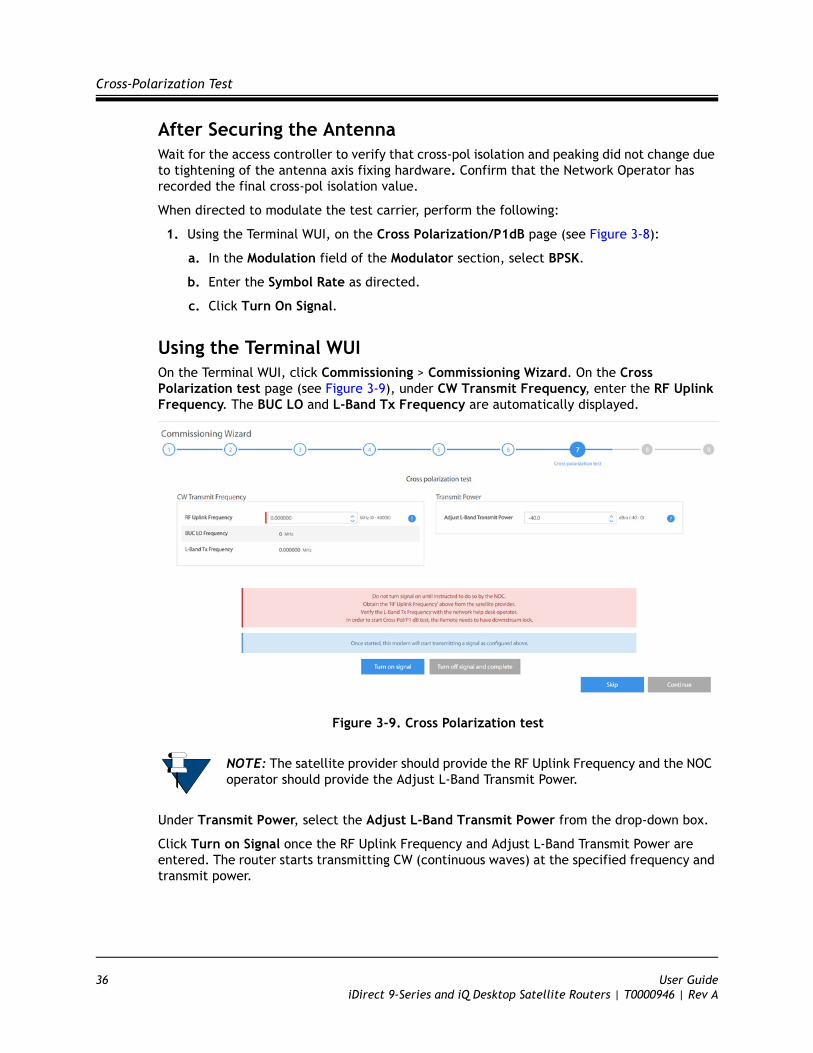
Using the Terminal WUIOn the Terminal WUI, click Commissioning > Commissioning Wizard. On the Cross Polarization test page (see Figure 3-9), under CW Transmit Frequency, enter the RF Uplink Frequency. The BUC LO and L-Band Tx Frequency are automatically displayed.
Figure 3-9. Cross Polarization test
Under Transmit Power, select the Adjust L-Band Transmit Power from the drop-down box.
Click Turn on Signal once the RF Uplink Frequency and Adjust L-Band Transmit Power are entered. The router starts transmitting CW (continuous waves) at the specified frequency and transmit power.
NOTE: The satellite provider should provide the RF Uplink Frequency and the NOC operator should provide the Adjust L-Band Transmit Power.
36 User GuideiDirect 9-Series and iQ Desktop Satellite Routers | T0000946 | Rev A
Cross-Polarization Test
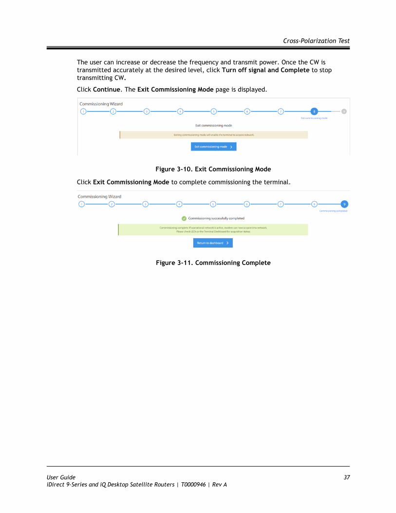
The user can increase or decrease the frequency and transmit power. Once the CW is transmitted accurately at the desired level, click Turn off signal and Complete to stop transmitting CW.
Click Continue. The Exit Commissioning Mode page is displayed.
Figure 3-10. Exit Commissioning Mode
Click Exit Commissioning Mode to complete commissioning the terminal.
Figure 3-11. Commissioning Complete
User Guide 37iDirect 9-Series and iQ Desktop Satellite Routers | T0000946 | Rev A

Cross-Polarization Test
38 User GuideiDirect 9-Series and iQ Desktop Satellite Routers | T0000946 | Rev A
Appendix A Acronyms and Abbreviations
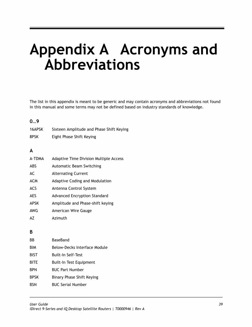
The list in this appendix is meant to be generic and may contain acronyms and abbreviations not found in this manual and some terms may not be defined based on industry standards of knowledge.
0…9
16APSK Sixteen Amplitude and Phase Shift Keying
8PSK Eight Phase Shift Keying
A
A-TDMA Adaptive Time Division Multiple Access
ABS Automatic Beam Switching
AC Alternating Current
ACM Adaptive Coding and Modulation
ACS Antenna Control System
AES Advanced Encryption Standard
APSK Amplitude and Phase-shift keying
AWG American Wire Gauge
AZ Azimuth
B
BB BaseBand
BIM Below-Decks Interface Module
BIST Built-In Self-Test
BITE Built-In Test Equipment
BPN BUC Part Number
BPSK Binary Phase Shift Keying
BSN BUC Serial Number
User Guide 39iDirect 9-Series and iQ Desktop Satellite Routers | T0000946 | Rev A
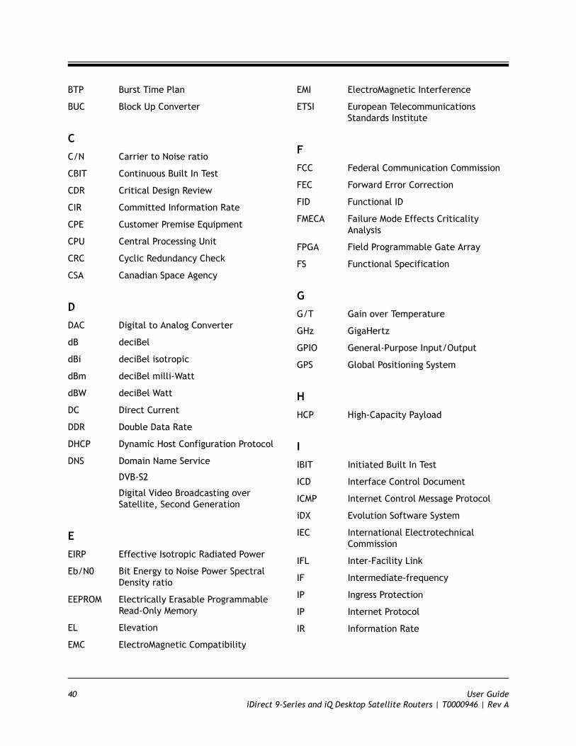
BTP Burst Time Plan
BUC Block Up Converter
C
C/N Carrier to Noise ratio
CBIT Continuous Built In Test
CDR Critical Design Review
CIR Committed Information Rate
CPE Customer Premise Equipment
CPU Central Processing Unit
CRC Cyclic Redundancy Check
CSA Canadian Space Agency
D
DAC Digital to Analog Converter
dB deciBel
dBi deciBel isotropic
dBm deciBel milli-Watt
dBW deciBel Watt
DC Direct Current
DDR Double Data Rate
DHCP Dynamic Host Configuration Protocol
DNS Domain Name Service
DVB-S2
Digital Video Broadcasting over Satellite, Second Generation
E
EIRP Effective Isotropic Radiated Power
Eb/N0 Bit Energy to Noise Power Spectral Density ratio
EEPROM Electrically Erasable Programmable Read-Only Memory
EL Elevation
EMC ElectroMagnetic Compatibility
EMI ElectroMagnetic Interference
ETSI European Telecommunications Standards Institute
F
FCC Federal Communication Commission
FEC Forward Error Correction
FID Functional ID
FMECA Failure Mode Effects Criticality Analysis
FPGA Field Programmable Gate Array
FS Functional Specification
G
G/T Gain over Temperature
GHz GigaHertz
GPIO General-Purpose Input/Output
GPS Global Positioning System
H
HCP High-Capacity Payload
I
IBIT Initiated Built In Test
ICD Interface Control Document
ICMP Internet Control Message Protocol
iDX Evolution Software System
IEC International Electrotechnical Commission
IFL Inter-Facility Link
IF Intermediate-frequency
IP Ingress Protection
IP Internet Protocol
IR Information Rate
40 User GuideiDirect 9-Series and iQ Desktop Satellite Routers | T0000946 | Rev A
J
K
kbps kilobit per second
kHz kilohertz
KRFU Ku/Ka-band Radio Frequency Unit
ksps kilosymbol per second
L
LAN Local Area Network
LDPC Low-Density Parity Coding
LED Light Emitting Diode
LNB Low Noise Block Converter
LOS Loss of Signal
LRU Line-Replaceable Unit
M
Mbps Megabits per second
Mcps Megachips per second
MES Mobile Earth Station
MF-TDMA Multi-Frequency TDMA
MHz Megahertz
MID Manufacturer ID
MIL-STD US Military Standard
MODCOD Modulation and Coding
Msps Mega Symbols per Second
MTBF Mean Time Between Failures
MTBUR Mean Time Between Unscheduled Removals
N
NAND Not AND
NF Noise Figure
NOR Not OR
NMS Network Management System
O
OAE Outside Antenna Equipment
ODU Outdoor Unit
OEM Original Equipment Manufacturer
OMT Orthogonal-Mode Transducer
OpenAMIP Open Antenna-Modem Interface Protocol
OTA Over The Air
OTP One Time Programmable
P
PA Power Amplifier
PAST Person-Activated Self-Test
PCB Printed Circuit Board
PC Personal Computer
PDR Preliminary Design Review
PLL Phased Locked Loop
PSK Phase Shift Keying
PSU Power Supply Unit
Q
QEF Quasi Error Free
QoS Quality of Service
QPSK Quadrature Phase Shift Keying
R
RF Radio Frequency
RGMII Reduced Gigabit Media Independent Interface
RMS Root Mean Square
RoHS Restriction of Hazardous Substances
ROM Read-Only Memory
RSSI Receive Signal Strength Indication
User Guide 41iDirect 9-Series and iQ Desktop Satellite Routers | T0000946 | Rev A

RTP Real-Time Protocol
Rx or RX Receive
S
SAS Satellite Access Station
SCPC Single Channel Per Carrier
SGMII Serial Gigabit Media Independent Interface
SIM Subscriber Identity Module
SNR Signal to Noise Ratio
SRS Systems Requirement Specification
SRU Shop Replaceable Unit
SSB Single Side Band
T
TBD To Be Defined
TCP Transmission Control Protocol
TDMA Time Division Multiple Access
TFI Terminal Functional ID
TMI Terminal Manufacturer ID
TPCFEC Turbo Product Code FEC
TPN Terminal Part Number
TSN Terminal Serial Number
TTC Terminal Transmit Control
Tx or TX Transmit
U
UDP Universal Data Protocol
UL Underwriters Laboratories
V
VAC Volts Alternating Current
VDC Volts Direct Current
VSAT Very Small Aperture Terminal
W
WFQ Weighted Fair Queuing
WGS Wideband Global SATCOM
X
X
Z
42 User GuideiDirect 9-Series and iQ Desktop Satellite Routers | T0000946 | Rev A
Appendix B Remote Locking
Soft, temporary, and hard locking for an iQ Desktop remote requires a unique Locking Key for each satellite router in combination with a Network Key and a randomly generated Confirmation Word to securely lock satellite routers to a network.
An iQ Desktop can be configured with a hard (permanent) lock. However, during the configuration of a hard lock, the network operator may choose to create a temporary lock. This is to allow a network operator to test the lock for the first iQ Desktop in order to verify operation, and to record the Netkey Fingerprint that is returned.
A hard locked satellite router cannot be unlocked; it must be returned to iDirect for a Non-Warranty RMA hardware replacement. A Netkey Fingerprint can help to avoid errors when locking the satellite router. The fingerprint identifies the network for the satellite router without revealing the Network Key on the satellite router.
A remote locked with a Soft Lock can be unlocked by entering the Confirmation Word provided when the lock was performed. If the Confirmation Word is lost, the soft lock cannot be disengaged. In order to unlock the remote, it must be returned to iDirect for a Non-Warranty RMA hardware replacement.
Remote locking is performed at the operator’s own risk. Non-Warranty RMA charges (plus all shipping) apply to all satellite routers returned to iDirect for the purpose of removing a network lock.
This appendix contains the following sections:
• Locking an iQ Desktop on page 44
• Configuring the Network Key on page 44
• Performing a Temporary Lock on page 44
• Performing a Soft Lock on page 46
WARNING: It is possible to remove a soft lock or temporary lock using the Terminal WUI. However, it is not possible to remove a hard lock using the Terminal WUI. Removing a hard lock requires returning the satellite router to iDirect for a Non-Warranty RMA hardware replacement.
NOTE: Non-Warranty RMA and shipping charges apply to all satellite routers returned to iDirect for the purpose of removing a network lock.
User Guide 43iDirect 9-Series and iQ Desktop Satellite Routers | T0000946 | Rev A
Locking an iQ Desktop
• Performing a Hard Lock on page 48
• Non-Warranty RMA Required to Remove Remote Locks on page 49
B.1 Locking an iQ Desktop Temporary, Soft, and/or Hard locking an iQ Desktop requires the following:
1. Creating the Network Key at the network level in iBuilder, and applying the changes. See Configuring the Network Key on page 44.
2. Connecting to the satellite router to be locked and entering the Network Key.
3. Generating the Netkey Fingerprint and Confirmation Word, and recording their values.
4. Entering the Confirmation Word and locking the remote.
B.2 Configuring the Network KeyRemote Locking of any sort requires the creation of a Network Key before locking the satellite routers to a network. Create the Network Key by configuring the following custom key on the Custom tab for the network in iBuilder:
[NETWORK_DEFINITION]net_key = <Network Key>
where <Network Key> is a string of between 5 and 64 alphanumeric characters.
After configuring the custom key in iBuilder, propagate the key to all satellite routers in the network by applying the changes to the network.
During operation, if a locked satellite router receives a Network Key message containing a Network Key that is different from the key set on the satellite router, the satellite router immediately stops sending upstream messages.
B.3 Performing a Temporary LockPerforming an optional Temporary Lock allows a network operator to test the locking of the first iQ Desktop, to verify operation, and to record the Netkey Fingerprint that is returned. Perform the following steps to temporarily lock the first iQ Desktop in a network.
1. Using a Web browser, connect to the satellite router to be locked and log on as developer. See Figure 1-1.
2. In the browser address bar, type /#admin-netlock to the right of the IP address. For example:
https://192.168.0.1/#admin-netlock
The Admin Netlock page is displayed. See Figure B-1.
NOTE: Locking a satellite router requires an developer login.
44 User GuideiDirect 9-Series and iQ Desktop Satellite Routers | T0000946 | Rev A
Performing a Temporary Lock
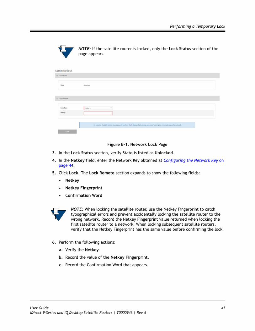
Figure B-1. Network Lock Page
3. In the Lock Status section, verify State is listed as Unlocked.
4. In the Netkey field, enter the Network Key obtained at Configuring the Network Key on page 44.
5. Click Lock. The Lock Remote section expands to show the following fields:
• Netkey
• Netkey Fingerprint
• Confirmation Word
6. Perform the following actions:
a. Verify the Netkey.
b. Record the value of the Netkey Fingerprint.
c. Record the Confirmation Word that appears.
NOTE: If the satellite router is locked, only the Lock Status section of the page appears.
NOTE: When locking the satellite router, use the Netkey Fingerprint to catch typographical errors and prevent accidentally locking the satellite router to the wrong network. Record the Netkey Fingerprint value returned when locking the first satellite router to a network. When locking subsequent satellite routers, verify that the Netkey Fingerprint has the same value before confirming the lock.
User Guide 45iDirect 9-Series and iQ Desktop Satellite Routers | T0000946 | Rev A
Performing a Soft Lock
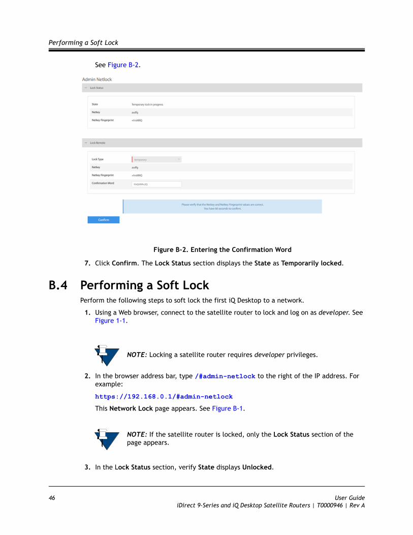
See Figure B-2.
Figure B-2. Entering the Confirmation Word
7. Click Confirm. The Lock Status section displays the State as Temporarily locked.
B.4 Performing a Soft LockPerform the following steps to soft lock the first iQ Desktop to a network.
1. Using a Web browser, connect to the satellite router to lock and log on as developer. See Figure 1-1.
2. In the browser address bar, type /#admin-netlock to the right of the IP address. For example:
https://192.168.0.1/#admin-netlock
This Network Lock page appears. See Figure B-1.
3. In the Lock Status section, verify State displays Unlocked.
NOTE: Locking a satellite router requires developer privileges.
NOTE: If the satellite router is locked, only the Lock Status section of the page appears.
46 User GuideiDirect 9-Series and iQ Desktop Satellite Routers | T0000946 | Rev A

Performing a Soft Lock
4. In the Lock Remote section, select Soft from the Lock type drop-down list.
5. In the Netkey field, enter the Network key obtained at Configuring the Network Key on page 44. See Figure B-3.
Figure B-3. Soft Lock Admin Netlock
6. Click Lock. The Lock Remote section expands to show the following fields:
• Netkey Fingerprint
• Confirmation Word
7. Perform the following actions:
a. Review the warning at the bottom of the page
b. Verify the Netkey.
c. Verify the value of the Netkey Fingerprint matches the value recorded in Section A3, Step 7.b.
d. Record the Confirmation Word.
NOTE: When locking the satellite router, use the Network Key Fingerprint to catch typographical errors and prevent accidentally locking the satellite router to the wrong network. Record the Network Key Fingerprint value returned when locking the first satellite router to a network. When locking subsequent satellite routers, verify that the Network Key Fingerprint has the same value before confirming the lock.
WARNING: Recording the Confirmation Word is critical. Without the Confirmation Word, the unit will have to be returned to iDirect under Non-Warranty RMA repair.
User Guide 47iDirect 9-Series and iQ Desktop Satellite Routers | T0000946 | Rev A
Performing a Hard Lock
e. Enter the Confirmation Word in the designated area.
8. Click Confirm. The Lock Status section shows the State is Soft locked.
B.5 Performing a Hard LockA hard lock permanently burns the Locking Key into the remote hardware using the generated Confirmation Word.
To hard lock a remote into the network, do the following:
1. In a Web browser, connect to the satellite router to be locked and log on as developer at the Terminal WUI. See Figure 1-1.
2. In the browser address bar, type /#admin-netlock to the right of the IP address. For example:
https://192.168.0.1/#admin-netlock
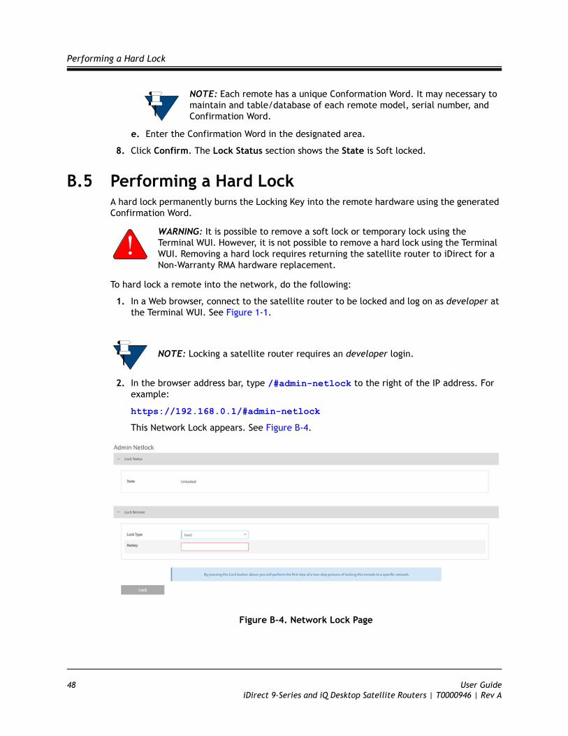
This Network Lock appears. See Figure B-4.
Figure B-4. Network Lock Page
NOTE: Each remote has a unique Conformation Word. It may necessary to maintain and table/database of each remote model, serial number, and Confirmation Word.
WARNING: It is possible to remove a soft lock or temporary lock using the Terminal WUI. However, it is not possible to remove a hard lock using the Terminal WUI. Removing a hard lock requires returning the satellite router to iDirect for a Non-Warranty RMA hardware replacement.
NOTE: Locking a satellite router requires an developer login.
48 User GuideiDirect 9-Series and iQ Desktop Satellite Routers | T0000946 | Rev A
Non-Warranty RMA Required to Remove Remote Locks
3. In the Lock Status section, verify State displays Unlocked.
4. In the Remote Lock section, select Hard from the Lock type drop-down list.
5. At the Netkey field, enter the Network Key obtained in Locking an iQ Desktop on page 44.
6. Click Lock. The Lock Status section expands to display the following fields:
• Netkey
• Netkey Fingerprint
• Confirmation Word
7. Perform the following actions:
a. Review the warning at the bottom of the page
b. Verify the Netkey.
c. Verify the value of the Netkey Fingerprint matches the value recorded in Performing a Temporary Lock
d. Enter the Confirmation Word in the designated area.
8. Click Confirm. A window opens showing the lock status of the satellite router.
B.6 Non-Warranty RMA Required to Remove Remote LocksIt is not possible to change or remove a lock on an iQ Desktop. In order to unlock the satellite router, return it to iDirect for a Non-Warranty RMA hardware replacement.
NOTE: If the satellite router is locked, only the Lock Status section of the page appears.
NOTE: When locking the satellite router, use the Network Key Fingerprint to catch typographical errors and prevent accidentally locking the satellite router to the wrong network. Record the Network Key Fingerprint value returned when locking the first satellite router to a network. When locking subsequent satellite routers, verify that the Network Key Fingerprint has the same value before confirming the lock.
WARNING: The following step will permanently lock the satellite router to the network. Only a hardware replacement can reverse this lock.
NOTE: Repeat these procedures to lock additional remotes.
User Guide 49iDirect 9-Series and iQ Desktop Satellite Routers | T0000946 | Rev A
Non-Warranty RMA Required to Remove Remote Locks
NOTE: RMA and shipping charges apply to all satellite routers returned to iDirect for the purpose of removing a network lock.
50 User GuideiDirect 9-Series and iQ Desktop Satellite Routers | T0000946 | Rev A


iDirect13861 Sunrise Valley Drive, Suite 300Herndon, VA 20171-6126+1 703.648.8000+1 866.345.0983
www.idirect.net
Advancing a Connected World