Embed Size (px)
Citation preview
Evolution of Physical Downlink Control Channel (PDCCH) for LTE-Advanced Systems
1,Bala Alhaji Salihu, 2Yang Dacheng, 3Zhang Xin, 4Suleiman Zubair
1Beijing University of Posts and Telecommunications, Wireless Theory and Technology Lab, PR China, [email protected], [email protected]
2Beijing University of Posts and Telecommunications, Wireless Theory and Technology Lab, PR China, [email protected]
3Beijing University of Posts and Telecommunications, Wireless Theory and Technology Lab, PR China, [email protected]
4UTM-MIMOS Centre of Excellence (CoE) in Telecommunication Technology Universiti Teknologi Malaysia, [email protected]
Abstract In progressive pattern, 3GPP has continued to expand and improve capacity of LTE data and
control channels especially for downlink transmissions. Among others, the physical downlink control channel (PDCCH) was designated in 3GPP LTE release 8 for sending downlink control information (DCI) to user equipment (UE), The DCI message is needed by every UE within the network in order to be served or serviced. The PDCCH make use of limited resource within the control region to perform this function. These resources become scarcer as the number of UEs increase within the network. As such, the PDCCH design becomes crucial to meet continuously increasing demand for ever increasing data transmission. Different designs have led to evolution of PDCCH in stages to suit scenarios and also fit new technologies introduced for LTE- Advanced systems. This article explains the underlying principles of PDCCH and how it has evolved to conform to the requirements of LTE-Advanced system specifications. We also provide some research opening for future breakthrough for DCI messaging.
Keywords: LTE, PDCCH, Relay, downlink control information (DCI), search space,
aggregation level.
1. Introduction
The early mobile communication technologies focused primarily on voice communication before the emphasis shifted to provision of systems optimized for data[1]. This voyage began with Wideband Code Division Multiple Access (WCDMA) system also called 3rd generation networks (3G) engineered by 3rd generation Partnership Project (3GPP), further enhancement of WCDMA in stages led to advent of another mobile communication technology known as Long-Term Evolution (LTE) showcased as 4th generation (4G). The dawn of LTE enables wide range of possibilities that were not obtainable in the previous technologies and provides solutions to challenges of its predecessors. E.g. amongst numerous functionality and flexibility of LTE we have wide-area coverage, seamless support for mobility, support for packet-switched data services and higher capacity[2]. Other requirements and targets for LTE can be found in[1, 3].
The LTE is built on new network architecture referred to as Evolved Packet System (EPS) describing both the evolved core network and an evolved Radio-Access Network (RAN). RAN is a non-hierarchical network platform with a single type of node known as evolved NodeB (eNB).The radio interface between the User Equipment (UE) and the network is divide into three layers, namely; Radio resource control layer (sub-layer of layer 3), Medium Access Control layer (sub-layer of layer 2) and layer 1(Physical layer)[4]. In this paper we focused our discussion more on the latter.
The role of physical layer is mainly to encipher data into a reliable signal for transmission across the radio interface between the eNB and the User Equipment (UE).Physical channels are defined for different purposes, some are either earmarked for downlink transmission or uplink transmission while the remainders are used for sending/ receiving control information. Remarkably, no any meaningful data flow in either direction (downlink or uplink) can take place without control information. Therefore, every user must first decode its control information successfully before it can establish any meaningful communication. Hence, the need for effective control signaling becomes indispensable. From onset
International Journal of Advancements in Computing Technology(IJACT) Volume 6, Number 1, January 2014
Evolution of Physical Downlink Control Channel (PDCCH) for LTE-Advanced Systems Bala Alhaji Salihu, Yang Dacheng, Zhang Xin, Suleiman Zubair
20
design, LTE frame structure dedicated some channels for data and they are called data channels while others for control information, known as control channels. In recent time, much data is needed in downlink compare to uplink direction; as such, emphases are more in optimizing downlink data rate. In this work, our discussion would be on downlink control channels.
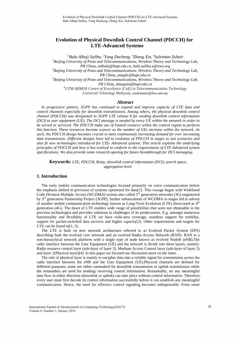
It is obvious that enhancing the capacity and performance of the LTE downlink data channels require corresponding improvement on the control channels. As shown in figure 1, the control region in LTE subframe comprise of Physical Hybrid ARQ Indicator Channel (PHICH), Physical Control Format Indicator Channel (PCFICH), Reference Signals (RS), synchronization signals (primary and secondary) and Physical Downlink Control CHannel (PDCCH). PDCCH is the most critical of all because it requires scheduling. Details of PDCCH framework and functionality will be provided in subsequent sections.
Snap look at figure 1, shows that the control region would be inadequate in a network deployment with significant large number of UEs because of limited resource (36 REs only) for the control region especially in Heterogeneous network (HetNet) and multi carrier networks. In this regard, 3GPP proposed enhanced PDCCH (EPDCCH) for LTE-Advanced systems and R-PDCCH for relay network.
The rest of the paper is organized as follows: in section 2 we discussed the underlying principle of PDCCH, section 3 provide the details for R-PDCCH in relay network. The framework of EPDCCH and its expected function are given in section 4, while in section 5 we discussed some possible research windows. Section 6 concludes the paper and point out the likely future breakthrough expected for DCI messaging.
Figure 1. Illustration of Control and Data region in LTE subframe
2. Physical Downlink Control Channel (PDCCH) Frameworks
PDCCH is one of the physical downlink control channels used for supporting efficient data
transmission in LTE. Its formation stem from release 8 and continued to evolve to-date in order to align with other technologies incorporated into LTE (examples of such new technologies include Carrier aggregation in release 10, Multiple Input Multiple Output antenna system MIMO etc.).
PDCCH carries a message known as Downlink Control Information (DCI), which includes transmission resource assignments, modulation and coding scheme and other control information for a UE or group of UEs. To accommodate different infrastructure and scenario especially UE capability, different DCI formats are adopted for PDCCH transmission, DCI formats is chosen based on the payload of DCI information and the channel coding rate[5]. Many PDCCHs can be transmitted in a subframe [6-8]. As depicted in figure 1. PDCCH and other control channels occupy up to three OFDM symbols in a subframe for a normal cyclic prefix for bandwidth higher than 1.4MHz. The frame structure in LTE can be described in time-frequency domain. One radio frame has time duration of 10ms subdivided into 20 slots. Each slot is 0.5ms. Two consecutive slots (1ms ) form a subframe. The time span of a subframe is referred to as Transmit Time Interval (TTI). A slot consists of seven OFDM symbols with normal cyclic prefix (CP) or six OFDM in case of extended CP. In frequency axis (vertical), every unit step is 15 kHz called sub-carriers. These spacing between two adjacent channels
Evolution of Physical Downlink Control Channel (PDCCH) for LTE-Advanced Systems Bala Alhaji Salihu, Yang Dacheng, Zhang Xin, Suleiman Zubair
21
(subcarriers) is always uniform (in width) regardless of total bandwidth in a system, see figure 1 for illustration.
A unit time-frequency forms a cube with dimension of 15 kHz in frequency axis and 1ms in time axis; this is known as Resource Element (RE). 12 consecutive subcarriers in frequency domain and a time of 7 OFDM symbols (a slot) in time domain is known as Resource Block (RB). Distinctively, out of 84 REs that made up one RB only 36 REs are reserved for control channel. In control region, four REs are grouped to form Resource Element Group (REG) and nine resource element groups (REGs) constitute a control channel element (CCE). PDCCH can only be mapped to CCEs. In effect, PDCCHs are constructed from CCEs.
The number of symbols used for PDCCH construction is always indicated by Physical Control Format Indicator Channel (PCFICH). Now that every UE must first receive and decode its PDCCHs from control region before it can be enabled to send or receive data the process for detecting PDCCH must be cleared. Without explicit signaling of such control message there would be complexity, particularly if UEs needed to search for their control information within all possible combinations of data, format and resource allocation. Analogously, this will be a sort of busy road network without traffic control. Further details of PDCCH detection process is explained below.
2.1. PDCCH Resource Allocation
Discussing PDCCH process cannot be isolated with Physical Downlink Shared Channel (PDSCH),
because the former is meant to serve or manage the latter. PDSCH is the principal data-bearing downlink channel. It is used for data, transmission of some system information not sent by Physical Broadcast Channel (PBCH), paging message and some other control signaling. Typically, the allocation of RBs to PDSCH transmission for a UE or group of UEs is signaled to UE at the beginning of subframe using PDCCH. The reason for positioning all the control channels at the beginning of subframe is to ensure that all the necessary requirements at both ends between the transmitter (eNB) and the receiver (UE) are adequately fulfilled prior to commencement of actual data transmission, and also to ensure that any UE that does not decode any PDCCH turns off its receiver circuitry for the remaining part (i.e.11 symbols) of the subframe to save power consumption. The amount of CCEs to be used to send PDCCH is determined by eNB to match the channel condition and the PDCCH format, which could be 0, 1, 2 or 3 depending on size of the bits to be transmitted. For UEs with good channel experience 1 or 2 CCEs is likely to suffice while for cell-edge UEs 4 or 8 CCEs may be required. The numbers of CCEs require for a particular UE is known as its aggregation level.
The CCE is the main resource of PDCCH. The relevant questions in PDCCH resource scheduling
are two; 1. Where would UE lookup for their possible PDCCH? 2. What is the format adopted for DCI payload at the transmitter end? The PDCCH configuration in LTE requires that each UE does blind decoding of a set of candidate locations (CCEs) to ascertain which, if any, contains its DCI information.
The set of candidates locations )(LM in which the UE may find its PDCCHs is referred to as search space. Specific and common search spaces are defined in LTE. The concept of search space is to partition the search area for the UEs so as to reduce the time for decoding especially for large bandwidths where there may be more numbers of PDCCH transmitted in a subframe. The sizes of the specific and common search spaces are already standardized by 3GPP as listed in table1. This answered the first question.
,
1
m o d ( 1 )
m o d
KA L
C C Ekk L T E
K K
A L m iA L
A D
NS P Y
Y Y
0, , 1i AL and ( )0, , 1Lm M . )( LM is the number of PDCCH candidates to monitor in a given
search space. Where 0RNTI1 nY , 3982A , 6553D and s 2k n , sn is the slot number within a
radio subframe. As shown Table 1, the relation for computing the search space of an UE in any given subframe is given as [9].
Evolution of Physical Downlink Control Channel (PDCCH) for LTE-Advanced Systems Bala Alhaji Salihu, Yang Dacheng, Zhang Xin, Suleiman Zubair
22
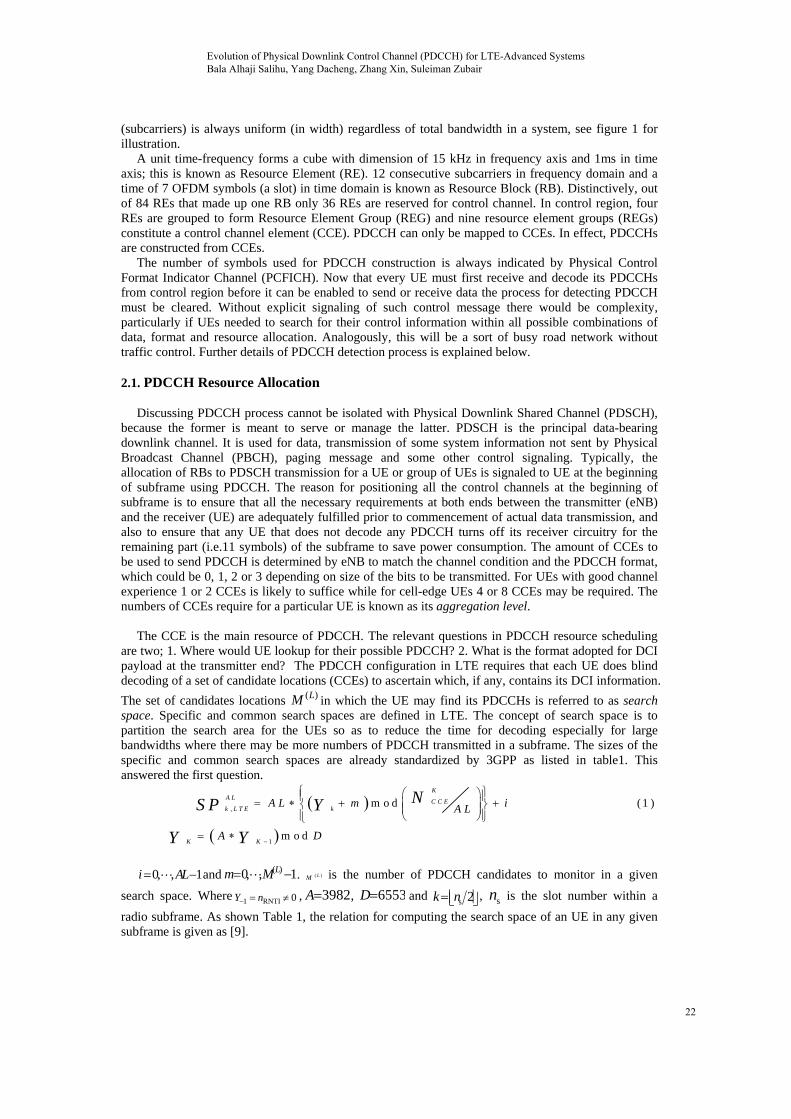
Looking closely at search space computation formula given in equation 1, from the table 1 it be seen that for UE with aggregation level 2 the search space size is 12 with 6 possible locations to monitor, another complexity may arise if UE does not know where to start probing within its search space. To simplify the search a start point is specified using the relation in equation 2.
Table 1. PDCCH candidates monitored and search Spaces sizes of UE
Type Aggregation level ( AL )
Search space Size [in CCEs]
,
A L
k L T ES P Number of PDCCH
candidates ( )(LM ) UE-specific 1 6 6
2 12 6 4 8 2
8 16 2
Common 4 16 4
8 16 2
,m o d ( 2 )
KA L
C C Ekk L T E
A L A LNS T Y
With confined search space for UEs there would be possibility that eNB cannot find sufficient CCEs
to send control information to all UEs not because the CCEs are all utilized but for the reason that the remainder of CCEs does not fall within the search space of un-serviced UEs. This situation may become worse in a multi carrier system with cross carrier scheduling enabled where one PDCCH is designed to service more than one PDSCH. To avert the possibility of such blocking, researchers have proposed different techniques as can be found in [9-12]. More works are still on going as regard ways to reduce blocking probability particularly for LTE-Advanced systems.
However, there is no clear answer to the second question; thus, UEs are required to blindly decode the DCI format. Though, the procedure for decoding is well fashioned. Before any DCI is sent a CRC is attached to its payload, the identity of the targeted UE is implicitly embedded in CRC. Different identity (Radio Network Temporary Identifier-RNTI) are used depending on the purpose of DCI message to be transmitted [13]. It is also clear from eq. (1) and eq. (2) that search space sizes for all aggregation levels are dependent on the available CCEs and the RNTI value. Number of CCE (NCCE) is determined by bandwidth. For instance, in a bandwidth of 10MHz there are 50 RBs, in each RB there are 36 REs meant for entire control channel region. In a pair RB we have 72 REs out of which PDCCH
may be allocated a fraction of 4 5 . So, the maximum NCCE available in a 10MHz bandwidth is 27
approximately. However, there are abundant RNTI values available for PDCCH, [14] mentioned the specified range as 003D to FFF3.
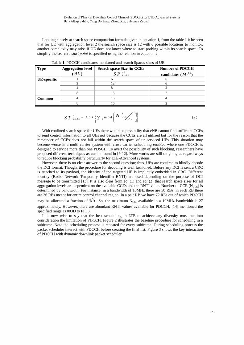
It is now wise to say that the best scheduling in LTE to achieve any diversity must put into consideration the limitation of PDCCH. Figure 2 illustrates the baseline procedure for scheduling in a subframe. Note the scheduling process is repeated for every subframe. During scheduling process the packet scheduler interact with PDCCH before creating the final list. Figure 3 shows the key interaction of PDCCH with dynamic downlink packet scheduler.
Evolution of Physical Downlink Control Channel (PDCCH) for LTE-Advanced Systems Bala Alhaji Salihu, Yang Dacheng, Zhang Xin, Suleiman Zubair
23
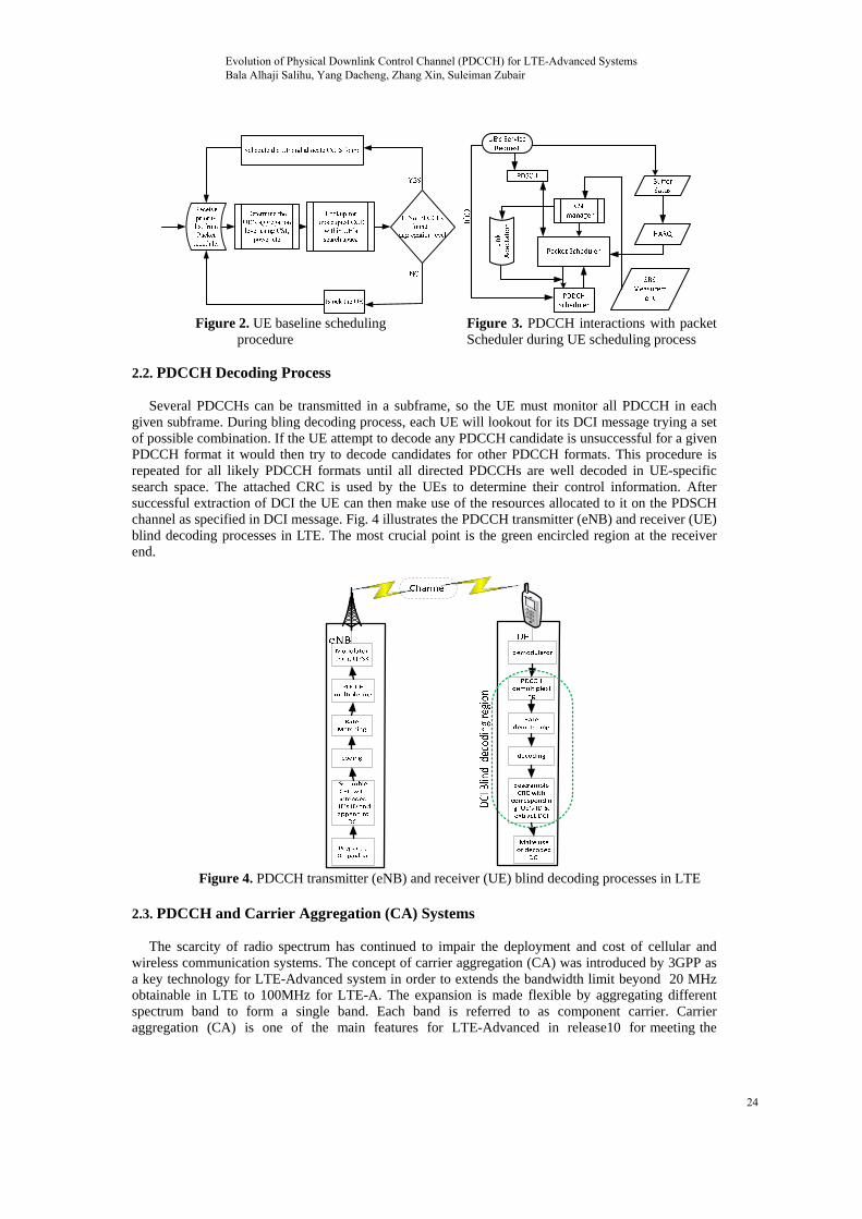
Figure 2. UE baseline scheduling
procedure Figure 3. PDCCH interactions with packet Scheduler during UE scheduling process
2.2. PDCCH Decoding Process
Several PDCCHs can be transmitted in a subframe, so the UE must monitor all PDCCH in each
given subframe. During bling decoding process, each UE will lookout for its DCI message trying a set of possible combination. If the UE attempt to decode any PDCCH candidate is unsuccessful for a given PDCCH format it would then try to decode candidates for other PDCCH formats. This procedure is repeated for all likely PDCCH formats until all directed PDCCHs are well decoded in UE-specific search space. The attached CRC is used by the UEs to determine their control information. After successful extraction of DCI the UE can then make use of the resources allocated to it on the PDSCH channel as specified in DCI message. Fig. 4 illustrates the PDCCH transmitter (eNB) and receiver (UE) blind decoding processes in LTE. The most crucial point is the green encircled region at the receiver end.
Figure 4. PDCCH transmitter (eNB) and receiver (UE) blind decoding processes in LTE
2.3. PDCCH and Carrier Aggregation (CA) Systems
The scarcity of radio spectrum has continued to impair the deployment and cost of cellular and
wireless communication systems. The concept of carrier aggregation (CA) was introduced by 3GPP as a key technology for LTE-Advanced system in order to extends the bandwidth limit beyond 20 MHz obtainable in LTE to 100MHz for LTE-A. The expansion is made flexible by aggregating different spectrum band to form a single band. Each band is referred to as component carrier. Carrier aggregation (CA) is one of the main features for LTE-Advanced in release10 for meeting the
Evolution of Physical Downlink Control Channel (PDCCH) for LTE-Advanced Systems Bala Alhaji Salihu, Yang Dacheng, Zhang Xin, Suleiman Zubair
24
peakdowoverComaggrtreatmeschanACKprim
HenviUE (comas thfor optishow
2.4.
Htransuchfor netwfemtRecNetwresudiredescprimof Popti
k data rate rewnlink respectirall system ba
mponent Carriregated resourted as release
ssaging were nges added to K/NACK per
mary compone
Having introduisioned to copin two ways;
mmon PDCCHhe release 8/9the second opon for cross-cws how the PD
Figu
PDCCH an
Having incorpsmission etc. h, another alteimprovement.
work) was revto, Remote Rently, NTT Dwork Architec
ulted into newct communicacription. Thermary of aim ofPDCCH to adjons.
equirements oively. CA enabandwidth [15,iers (CC) whilrce. The CCs c8 carrier. Howenhanced in physical layercomponent ca
ent carrier of th
uced CA techpe with new ch
same carrier H for multiple9 PDCCH struption, New 3-carrier schedulDCCH are con
ure 5. PDCCH
nd Heterogen
orated technolinto LTE-Adv
ernative was in. The popular
visited. In so dRadio Head (
DoCoMo propocture (C-RAN
w topology foation betweenrefore, PDCCf introducing Hudicate HetN
of IMT-Advanbles multiple c, 16]. Releaselst Rel-10 UEcan be of diffewever, for relorder to accor protocol is sarrier. The carhat particular U
hnology in Relhallenges. Froscheduling (s
e component cucture and DC-bit Carrier Inling is to allow
nfigure with di
H configuratio
neous Netwo
logies like carvanced, the ranevitable. 3GPr macro statiodoing, the mix(RRH), and rosed new lookN)[19]. Theor LTE-A knon eNB and UH protocol nHetNet is to bet complexity
nced, namely component cae 8/9 UEs canEs can be alloerent bandwidease10 UEs so
ommodate moignaling of serrier that handUE.
l-10, the needom schedulingseparate PDCCcarriers)[18]. T
CI formats are ndicator Field w control chaifferent option
on options for
ork (HetNet)
rrier aggregatidio link perfoPP then consion-only netwox of macro starelay base-stak for next gen
overlying of own as Heter
UEs is now inneeded to be oost network
y opened anoth
500 Mbps anarriers (CCs) ton be allocated
ocated downlindths [17].Primaome physical
ore than one condary compdles the RRC
d for expanding perspective,CH for each CThe first optio maintained b(CIF) is add
annel to spans ns.
Multi carrier
) Scenario
ion, MIMO, cormance tend tidered networkork topology ations and lowations) were ceration eNB u
f low power rogeneous Netnterceded by complimentedcoverage and her window fo
nd 1 Gbps foo be aggregated resources onk and uplinkarily, each comlayer protococarrier. One
ponent carrier connection of
ng the functionresources can
CC) or cross-con does not pobut it encouragded to release
the entire ban
systems in LT
oordinated muto approach thk topology as(also known
w power nodesconsidered asusing Centraliznodes on matwork (HetNeLPN. See figd to fit this capacity[20].
or researchers
or the uplink ed to form a wn any one of
k resources onmponent carril, MAC and Rof the signifias well as HAf UE is know
n of PDCCH n be allocated carrier scheduose any challeges wastages. 8 DCI. Ano
ndwidth. Figu
TE-Advanced
ulti-point (CoMheoretical limis the new win
as homogenes LPN (such ps best alternatzed Radio Ac
acro stations tet). With HetNgure 6 for simscenario. OneThe modifica to propose be
and wider f the n the er is
RRC icant ARQ
wn as
was to a
uling enge But
other ure 5
MP) it, as dow eous pico, tive.
ccess then
tNet, mple e of ation etter
Evolution of Physical Downlink Control Channel (PDCCH) for LTE-Advanced Systems Bala Alhaji Salihu, Yang Dacheng, Zhang Xin, Suleiman Zubair
25
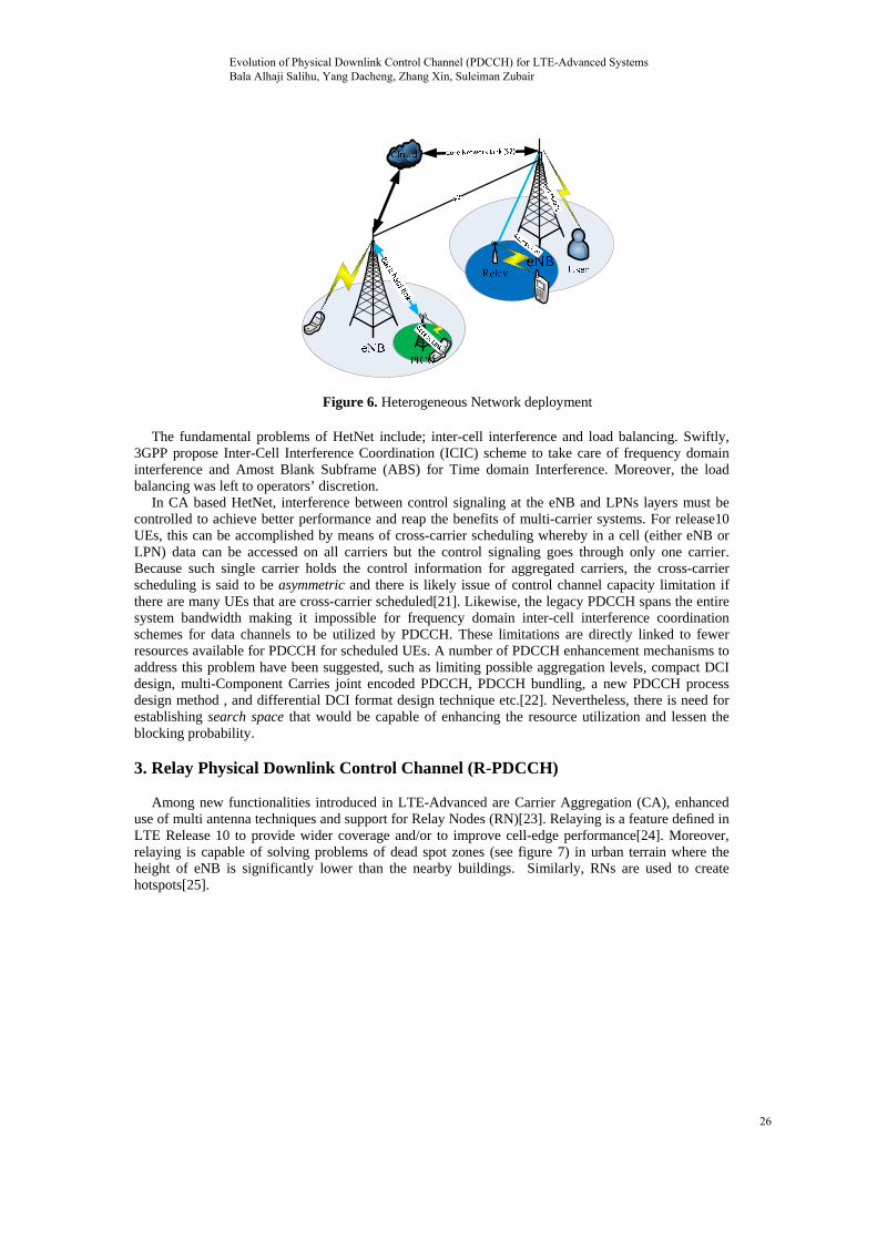
Figure 6. Heterogeneous Network deployment
The fundamental problems of HetNet include; inter-cell interference and load balancing. Swiftly,
3GPP propose Inter-Cell Interference Coordination (ICIC) scheme to take care of frequency domain interference and Amost Blank Subframe (ABS) for Time domain Interference. Moreover, the load balancing was left to operators’ discretion.
In CA based HetNet, interference between control signaling at the eNB and LPNs layers must be controlled to achieve better performance and reap the benefits of multi-carrier systems. For release10 UEs, this can be accomplished by means of cross-carrier scheduling whereby in a cell (either eNB or LPN) data can be accessed on all carriers but the control signaling goes through only one carrier. Because such single carrier holds the control information for aggregated carriers, the cross-carrier scheduling is said to be asymmetric and there is likely issue of control channel capacity limitation if there are many UEs that are cross-carrier scheduled[21]. Likewise, the legacy PDCCH spans the entire system bandwidth making it impossible for frequency domain inter-cell interference coordination schemes for data channels to be utilized by PDCCH. These limitations are directly linked to fewer resources available for PDCCH for scheduled UEs. A number of PDCCH enhancement mechanisms to address this problem have been suggested, such as limiting possible aggregation levels, compact DCI design, multi-Component Carries joint encoded PDCCH, PDCCH bundling, a new PDCCH process design method , and differential DCI format design technique etc.[22]. Nevertheless, there is need for establishing search space that would be capable of enhancing the resource utilization and lessen the blocking probability.
3. Relay Physical Downlink Control Channel (R-PDCCH)
Among new functionalities introduced in LTE-Advanced are Carrier Aggregation (CA), enhanced
use of multi antenna techniques and support for Relay Nodes (RN)[23]. Relaying is a feature defined in LTE Release 10 to provide wider coverage and/or to improve cell-edge performance[24]. Moreover, relaying is capable of solving problems of dead spot zones (see figure 7) in urban terrain where the height of eNB is significantly lower than the nearby buildings. Similarly, RNs are used to create hotspots[25].
Evolution of Physical Downlink Control Channel (PDCCH) for LTE-Advanced Systems Bala Alhaji Salihu, Yang Dacheng, Zhang Xin, Suleiman Zubair
26

DeNB
Dead spot
UE
UE
Hotspot zone
UE
UERN
RN
Wireless camera
Figure 7. Using Relay for Dead Spot and Hotspot zones
A relay-assisted communication network is a typical heterogeneous network as described in figure 6.
The backhaul link (Un) and the access link (Uu) cannot be treated the same way in most cases for efficiency. The capacity and/or robustness of the backhaul link are fundamental to any successful HetNet with relay. Therefore, using the legacy PDCCH to serve the LPNs (Relay Node) for control signaling was found to be inefficient. Hence, the necessity for separate channel ensued. The new channel known as Relay- PDCCH (R-PDCCH) was proposed and found to be an efficient way out[26]. This channel was not unwarranted because of advantages of relaying in LTE, some of these advantages are briefly introduced in[26, 27] and its different relay architectures could be found in [28]. Donor eNB DeNB-to-RN transmissions are bounded to a subset of the OFDM symbols in a slot. The starting and ending OFDM symbols respectively in the first and second slot of a subframe varies and are clearly specified in a table as in[29].
The new control channel (R-PDCCH) signaling is transmitted outside legacy control region (see figure 8), for backhauling the link between the donor eNB (DeNB) and the relay node (RN) using a semi-statically configured set of resource blocks (RBs). It means that the R-PDCCH make use of data channel resources and is time and frequency multiplex with PDSCH. Hence, the legacy PDCCH is less affected by introduction of R-PDCCH. However, using R-PDCCH would be a prohibitive overhead in a scenario where the backhaul link (DeNBRN) and access links (RNUE) are in different frequency bands or when there is an ample antenna isolation between the two links (“full-duplex relay”) or when the need for subframe alignment between RN and DeNB is not necessary then the legacy PDCCH can gainfully be utilized. Using the PDCCH in such instances would curb the overhead for reserved “R-PDCCH resources” as well as limit the “trunking loss” between directly connected UEs and RNs present when the R-PDCCH is used[30]. In simple terms, one can say R-PDCCH usage is an extension of the PDCCH to address additional scenarios but not a replacement per se. [25]. In general, the relay physical downlink control channel (R-PDCCH) carries DCI for relay nodes.
Data transmission on the Un link makes use of the same physical channels as defined for the direct UEs. There are three options for multiplexing R-PDCCH and PDSCH in data region with respect to how R-PDCCH are configured within physical resource block they occupy viz:
i. Downlink assignment in the first and uplink grant in the second slot ii. Only a downlink assignment in the first slot iii. Only an uplink assignment in the second slot
As depicted in figure 8, in the first option, it is preferable to have the second slot of such PRB for PDSCH data transmission to the same RN that is using the first slot for R-PDCCH. In this pattern, the RN would be aware that the first slot was used to transmit R-PDCCH, and can hence perfectly assume that only the second slot of that RB pair is meant for data transmission.
For the third option, it is much better to leave the first slot unused than to use it for PDSCH transmission for either the same relay or another. Though, it is possible but the benefit does not worth the cost. Because, the available number of REs that could be used for PDSCH in the first slot is smaller than in the second. Therefore, transmission of PDSCH in the third option is practically infeasible and discouraged.
Evolution of Physical Downlink Control Channel (PDCCH) for LTE-Advanced Systems Bala Alhaji Salihu, Yang Dacheng, Zhang Xin, Suleiman Zubair
27
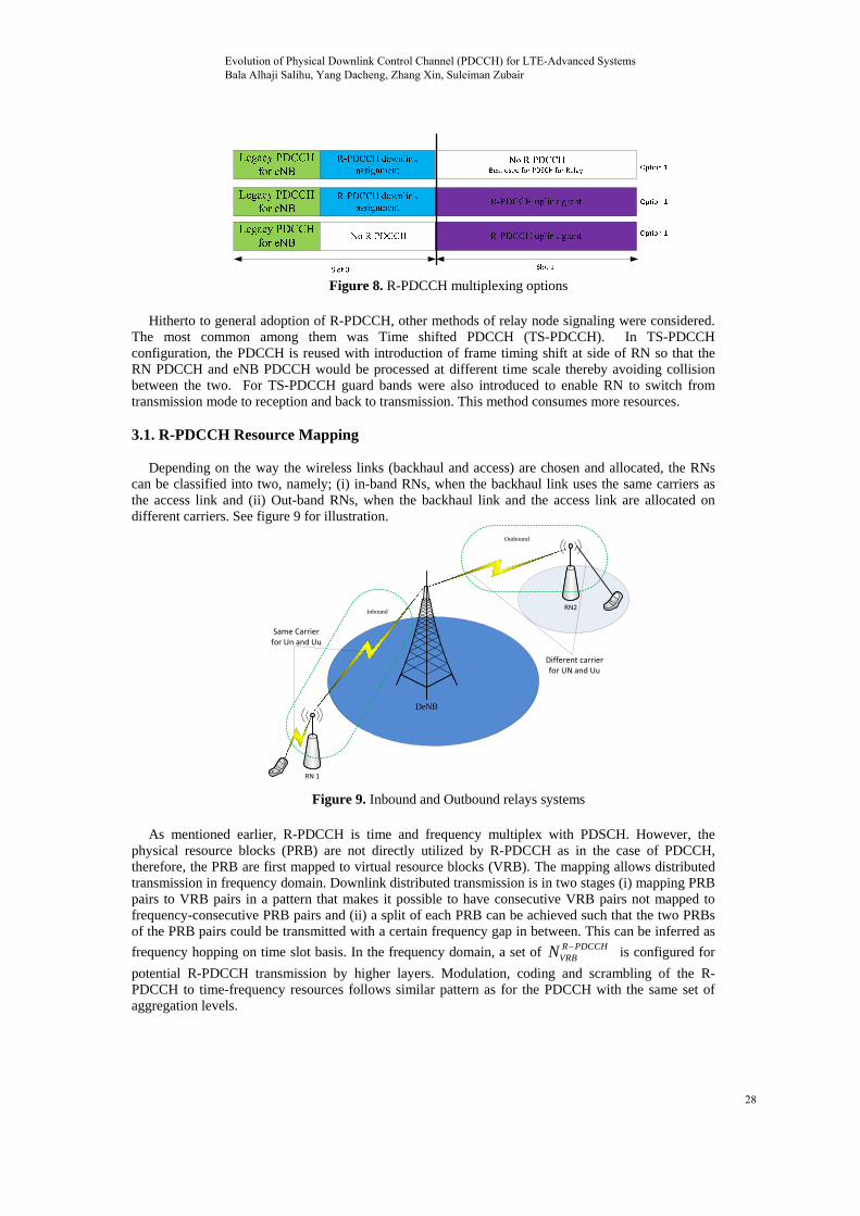
Figure 8. R-PDCCH multiplexing options
Hitherto to general adoption of R-PDCCH, other methods of relay node signaling were considered.
The most common among them was Time shifted PDCCH (TS-PDCCH). In TS-PDCCH configuration, the PDCCH is reused with introduction of frame timing shift at side of RN so that the RN PDCCH and eNB PDCCH would be processed at different time scale thereby avoiding collision between the two. For TS-PDCCH guard bands were also introduced to enable RN to switch from transmission mode to reception and back to transmission. This method consumes more resources.
3.1. R-PDCCH Resource Mapping
Depending on the way the wireless links (backhaul and access) are chosen and allocated, the RNs
can be classified into two, namely; (i) in-band RNs, when the backhaul link uses the same carriers as the access link and (ii) Out-band RNs, when the backhaul link and the access link are allocated on different carriers. See figure 9 for illustration.
RN 1
RN2
DeNB
Same Carrier for Un and Uu
Different carrier for UN and Uu
Inbound
Outbound
Figure 9. Inbound and Outbound relays systems
As mentioned earlier, R-PDCCH is time and frequency multiplex with PDSCH. However, the
physical resource blocks (PRB) are not directly utilized by R-PDCCH as in the case of PDCCH, therefore, the PRB are first mapped to virtual resource blocks (VRB). The mapping allows distributed transmission in frequency domain. Downlink distributed transmission is in two stages (i) mapping PRB pairs to VRB pairs in a pattern that makes it possible to have consecutive VRB pairs not mapped to frequency-consecutive PRB pairs and (ii) a split of each PRB can be achieved such that the two PRBs of the PRB pairs could be transmitted with a certain frequency gap in between. This can be inferred as
frequency hopping on time slot basis. In the frequency domain, a set of R PDCCHVRBN is configured for
potential R-PDCCH transmission by higher layers. Modulation, coding and scrambling of the R-PDCCH to time-frequency resources follows similar pattern as for the PDCCH with the same set of aggregation levels.
Evolution of Physical Downlink Control Channel (PDCCH) for LTE-Advanced Systems Bala Alhaji Salihu, Yang Dacheng, Zhang Xin, Suleiman Zubair
28
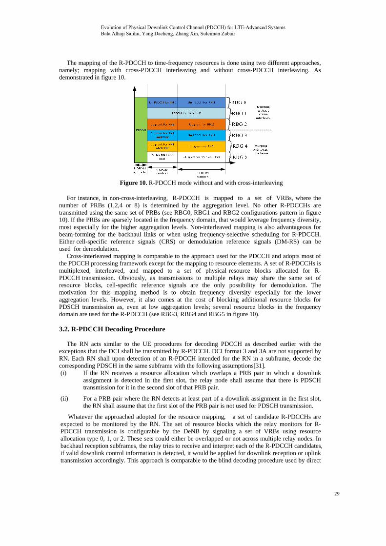
The mapping of the R-PDCCH to time-frequency resources is done using two different approaches, namely; mapping with cross-PDCCH interleaving and without cross-PDCCH interleaving. As demonstrated in figure 10.
Figure 10. R-PDCCH mode without and with cross-interleaving
For instance, in non-cross-interleaving, R-PDCCH is mapped to a set of VRBs, where the
number of PRBs (1,2,4 or 8) is determined by the aggregation level. No other R-PDCCHs are transmitted using the same set of PRBs (see RBG0, RBG1 and RBG2 configurations pattern in figure 10). If the PRBs are sparsely located in the frequency domain, that would leverage frequency diversity, most especially for the higher aggregation levels. Non-interleaved mapping is also advantageous for beam-forming for the backhaul links or when using frequency-selective scheduling for R-PDCCH. Either cell-specific reference signals (CRS) or demodulation reference signals (DM-RS) can be used for demodulation.
Cross-interleaved mapping is comparable to the approach used for the PDCCH and adopts most of the PDCCH processing framework except for the mapping to resource elements. A set of R-PDCCHs is multiplexed, interleaved, and mapped to a set of physical resource blocks allocated for R-PDCCH transmission. Obviously, as transmissions to multiple relays may share the same set of resource blocks, cell-specific reference signals are the only possibility for demodulation. The motivation for this mapping method is to obtain frequency diversity especially for the lower aggregation levels. However, it also comes at the cost of blocking additional resource blocks for PDSCH transmission as, even at low aggregation levels; several resource blocks in the frequency domain are used for the R-PDCCH (see RBG3, RBG4 and RBG5 in figure 10).
3.2. R-PDCCH Decoding Procedure
The RN acts similar to the UE procedures for decoding PDCCH as described earlier with the
exceptions that the DCI shall be transmitted by R-PDCCH. DCI format 3 and 3A are not supported by RN. Each RN shall upon detection of an R-PDCCH intended for the RN in a subframe, decode the corresponding PDSCH in the same subframe with the following assumptions[31]. (i) If the RN receives a resource allocation which overlaps a PRB pair in which a downlink
assignment is detected in the first slot, the relay node shall assume that there is PDSCH transmission for it in the second slot of that PRB pair.
(ii) For a PRB pair where the RN detects at least part of a downlink assignment in the first slot, the RN shall assume that the first slot of the PRB pair is not used for PDSCH transmission.
Whatever the approached adopted for the resource mapping, a set of candidate R-PDCCHs are expected to be monitored by the RN. The set of resource blocks which the relay monitors for R-PDCCH transmission is configurable by the DeNB by signaling a set of VRBs using resource allocation type 0, 1, or 2. These sets could either be overlapped or not across multiple relay nodes. In backhaul reception subframes, the relay tries to receive and interpret each of the R-PDCCH candidates, if valid downlink control information is detected, it would be applied for downlink reception or uplink transmission accordingly. This approach is comparable to the blind decoding procedure used by direct
Evolution of Physical Downlink Control Channel (PDCCH) for LTE-Advanced Systems Bala Alhaji Salihu, Yang Dacheng, Zhang Xin, Suleiman Zubair
29
UEs to decode their PDCCH, although there are differences in some respect. First, because there is no need to receive broadcast information, the need for common search spaces for the relays is unwarranted. Any information necessary for relay operation is transmitted using dedicated signaling. Secondly, the search spaces for the non-interleaved mapping remain static in time unlike the ones for UEs that varies with time.
RN procedure for determining R-PDCCH assignment depends on whether the mapping is with or without cross-interleaving. For cross inter-leaving, release 8 search space is reused. On the other hand, without cross-interleaving, the starting CCE position of RN-specific search space is the first PRB of the configured RN-specific R-PDCCH region. During the decoding process relays only monitor specific search space as there is no common search space defined, this is logical because relays does not receive broadcast as UEs. Whenever the higher-layers configure the R-PDCCH to be cross-interleaved, the relay node procedure for determining the R-PDCCH assignment is according to the UE procedure for determining PDCCH assignment.
The set of CCEs to be monitored by each R-PDCCH candidate m of search space ,AL
k tSP in slot
0,1t of subframe k is given as ,modR PDCCHCCE k
k
NAL Y m iAL
where i =0, 1,…, 1M , and
,R PDCCHCCE kN
is the number of CCEs in the set of RBs allocated for possible R-PDCCH transmission.
However, without cross-interleaved, the same set of VRBs is configured for a possible R-PDCCH in
the first and in the second slot. In each slot, any R-PDCCH candidate 0,1,... 1m M at
aggregation level AL includes VRB numbered with ,. modR PDCCH R PDCCHVRB CCE kn AL m i N
where 0,1,... 1i AL and M remain the same as for the UEs.
Obviously, the number of R-PDCCH candidates to monitor is the same as for a UE (see table 1). Another point to note is that an R-PDCCH can be transmitted in either first or second slot of a subframe. Hence, the total number of decoding attempts performed by a relay is 64[32].” No PHICH channel is defined for the backhaul. The main reason for the PHICH in release 8 was efficient support of non-adaptive retransmissions for delay-sensitive low-rate applications such as voice-over IP. The backhaul from a relay, on the other hand, typically uses a higher data rate as multiple UEs are served by the relay. Thus, as control signaling overhead is less of an issue, the PHICH was omitted from the backhaul in order to simplify the overall design. Retransmissions are still supported through the use of the R-PDCCH”.
4. Enhanced PDCCH Frame Work
Due to limitation of PDCCH, enhanced PDCCH (EPDCCH) was introduced in release 11 to figure
out most of legacy PDCCH constraints. Besides supplementing the control channel capacity, the EPDCCH was also meant to provide the following benefits [8, 33];
• aid frequency-domain intercell interference coordination • enriched spatial reuse (e.g., MIMO) • ease frequency-selective scheduling • support operation in multicast-broadcast single-frequency network (MBSFN) subframes • beamforming • coexistence on the same carrier with legacy PDCCH
The immediate question that needs to be answered is the source of EPDCCH resources. Just like R-PDCCH, EPDCCH does not derive its resources from the legacy control region of a normal LTE subframe so that interference with legacy PDCCH would not be in question. Instead, the EPDCCH is Frequency Division Multiplexed (FDM) with the PDSCH, and occupies a subset of physical resource block pairs within system bandwidth. See figure 11 for illustration of EPDCCH location with a subframe. Moreover, the multiplexing of EPDCCH and PDSCH in a PRB pair is not favorable except by FDM, outside FDM multiplexing, it will introduce extra signaling overhead. If such multiplexing were allowed in one PRB pair, new signaling would be desired to indicate which resource element or sub-carriers within PRB pair are used for PDSCH. For the fact that EPDCCH and PDSCH are
Evolution of Physical Downlink Control Channel (PDCCH) for LTE-Advanced Systems Bala Alhaji Salihu, Yang Dacheng, Zhang Xin, Suleiman Zubair
30
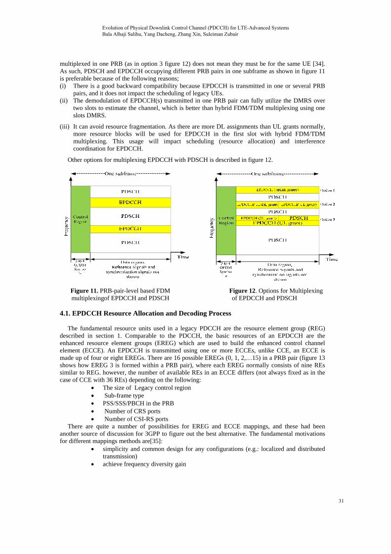
multiplexed in one PRB (as in option 3 figure 12) does not mean they must be for the same UE [34]. As such, PDSCH and EPDCCH occupying different PRB pairs in one subframe as shown in figure 11 is preferable because of the following reasons; (i) There is a good backward compatibility because EPDCCH is transmitted in one or several PRB
pairs, and it does not impact the scheduling of legacy UEs. (ii) The demodulation of EPDCCH(s) transmitted in one PRB pair can fully utilize the DMRS over
two slots to estimate the channel, which is better than hybrid FDM/TDM multiplexing using one slots DMRS.
(iii) It can avoid resource fragmentation. As there are more DL assignments than UL grants normally, more resource blocks will be used for EPDCCH in the first slot with hybrid FDM/TDM multiplexing. This usage will impact scheduling (resource allocation) and interference coordination for EPDCCH.
Other options for multiplexing EPDCCH with PDSCH is described in figure 12.
Figure 11. PRB-pair-level based FDM multiplexingof EPDCCH and PDSCH
Figure 12. Options for Multiplexing of EPDCCH and PDSCH
4.1. EPDCCH Resource Allocation and Decoding Process
The fundamental resource units used in a legacy PDCCH are the resource element group (REG)
described in section 1. Comparable to the PDCCH, the basic resources of an EPDCCH are the enhanced resource element groups (EREG) which are used to build the enhanced control channel element (ECCE). An EPDCCH is transmitted using one or more ECCEs, unlike CCE, an ECCE is made up of four or eight EREGs. There are 16 possible EREGs (0, 1, 2,…15) in a PRB pair (figure 13 shows how EREG 3 is formed within a PRB pair), where each EREG normally consists of nine REs similar to REG. however, the number of available REs in an ECCE differs (not always fixed as in the case of CCE with 36 REs) depending on the following:
The size of Legacy control region Sub-frame type PSS/SSS/PBCH in the PRB Number of CRS ports Number of CSI-RS ports
There are quite a number of possibilities for EREG and ECCE mappings, and these had been another source of discussion for 3GPP to figure out the best alternative. The fundamental motivations for different mappings methods are[35]:
simplicity and common design for any configurations (e.g.: localized and distributed transmission)
achieve frequency diversity gain
Evolution of Physical Downlink Control Channel (PDCCH) for LTE-Advanced Systems Bala Alhaji Salihu, Yang Dacheng, Zhang Xin, Suleiman Zubair
31
make it possible to randomize interference in different deployment scenarios (e.g.: HetNet and CoMP)
support ECCE level or PRB level ICIC closely align with legacy PDCCH design
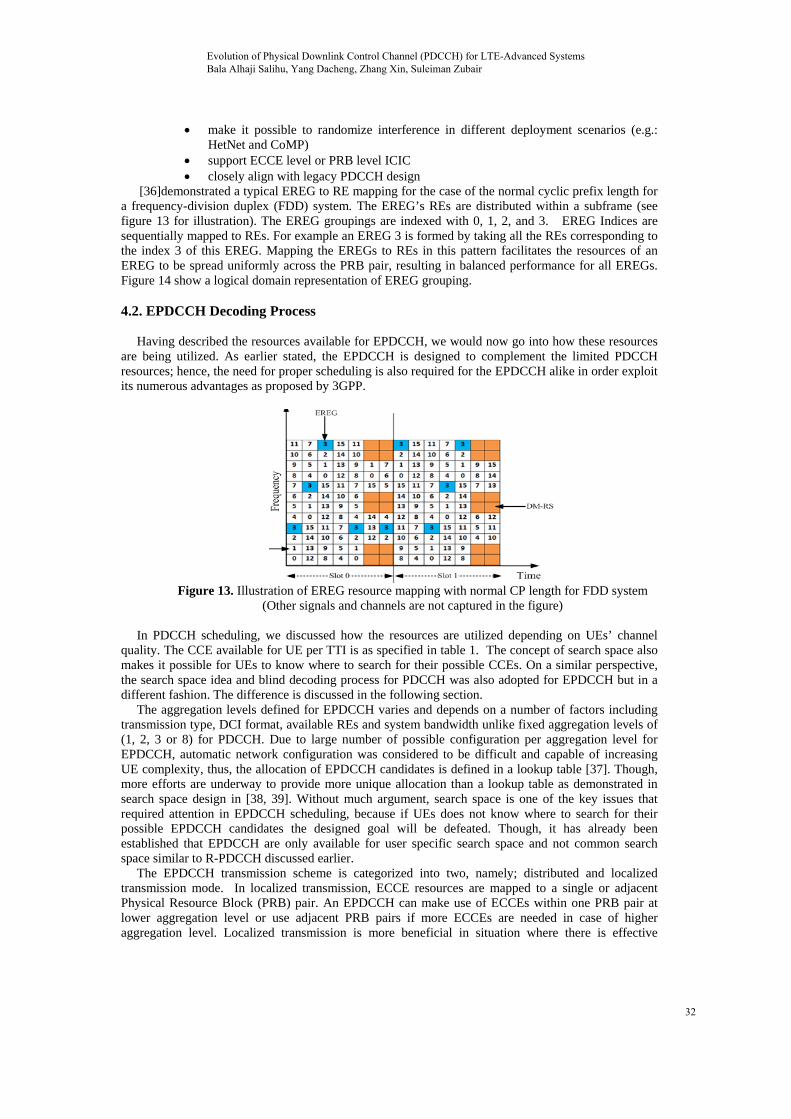
[36]demonstrated a typical EREG to RE mapping for the case of the normal cyclic prefix length for a frequency-division duplex (FDD) system. The EREG’s REs are distributed within a subframe (see figure 13 for illustration). The EREG groupings are indexed with 0, 1, 2, and 3. EREG Indices are sequentially mapped to REs. For example an EREG 3 is formed by taking all the REs corresponding to the index 3 of this EREG. Mapping the EREGs to REs in this pattern facilitates the resources of an EREG to be spread uniformly across the PRB pair, resulting in balanced performance for all EREGs. Figure 14 show a logical domain representation of EREG grouping.
4.2. EPDCCH Decoding Process
Having described the resources available for EPDCCH, we would now go into how these resources
are being utilized. As earlier stated, the EPDCCH is designed to complement the limited PDCCH resources; hence, the need for proper scheduling is also required for the EPDCCH alike in order exploit its numerous advantages as proposed by 3GPP.
Figure 13. Illustration of EREG resource mapping with normal CP length for FDD system
(Other signals and channels are not captured in the figure)
In PDCCH scheduling, we discussed how the resources are utilized depending on UEs’ channel quality. The CCE available for UE per TTI is as specified in table 1. The concept of search space also makes it possible for UEs to know where to search for their possible CCEs. On a similar perspective, the search space idea and blind decoding process for PDCCH was also adopted for EPDCCH but in a different fashion. The difference is discussed in the following section.
The aggregation levels defined for EPDCCH varies and depends on a number of factors including transmission type, DCI format, available REs and system bandwidth unlike fixed aggregation levels of (1, 2, 3 or 8) for PDCCH. Due to large number of possible configuration per aggregation level for EPDCCH, automatic network configuration was considered to be difficult and capable of increasing UE complexity, thus, the allocation of EPDCCH candidates is defined in a lookup table [37]. Though, more efforts are underway to provide more unique allocation than a lookup table as demonstrated in search space design in [38, 39]. Without much argument, search space is one of the key issues that required attention in EPDCCH scheduling, because if UEs does not know where to search for their possible EPDCCH candidates the designed goal will be defeated. Though, it has already been established that EPDCCH are only available for user specific search space and not common search space similar to R-PDCCH discussed earlier.
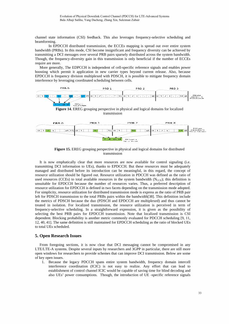
The EPDCCH transmission scheme is categorized into two, namely; distributed and localized transmission mode. In localized transmission, ECCE resources are mapped to a single or adjacent Physical Resource Block (PRB) pair. An EPDCCH can make use of ECCEs within one PRB pair at lower aggregation level or use adjacent PRB pairs if more ECCEs are needed in case of higher aggregation level. Localized transmission is more beneficial in situation where there is effective
Evolution of Physical Downlink Control Channel (PDCCH) for LTE-Advanced Systems Bala Alhaji Salihu, Yang Dacheng, Zhang Xin, Suleiman Zubair
32
channel state information (CSI) feedback. This also leverages frequency-selective scheduling and beamforming.
In EPDCCH distributed transmission, the ECCEs mapping is spread out over entire system bandwidth (PRBs). In this mode, CSI become insignificant and frequency diversity can be achieved by transmitting a DCI messages over several PRB pairs sparsely distributed across the system bandwidth. Though, the frequency-diversity gain in this transmission is only beneficial if the number of ECCEs require are more.
More generally, The EDPCCH is independent of cell-specific reference signals and enables power boosting which permit it application in new carrier types beyond current release. Also, because EPDCCH is frequency division multiplexed with PDSCH, it is possible to mitigate frequency domain interference by leveraging coordinated scheduling between cells.
Figure 14. EREG grouping perspective in physical and logical domains for localized transmission
Figure 15. EREG grouping perspective in physical and logical domains for distributed
transmission
It is now emphatically clear that more resources are now available for control signaling (i.e. transmitting DCI information to UEs), thanks to EPDCCH. But these resources must be adequately managed and distributed before its introduction can be meaningful, in this regard, the concept of resource utilization should be figured out. Resource utilization in PDCCH was defined as the ratio of used resources (CCEs) to total available resources in the system bandwidth (NCCE); this definition is unsuitable for EPDCCH because the number of resources varies. Thus, a preferred description of resource utilization for EPDCCH is defined in two facets depending on the transmission mode adopted. For simplicity, resource utilization for distributed transmission mode is express as the ratio of PRB pair left for PDSCH transmission to the total PRBs pairs within the bandwidth[38]. This definition include the metrics of PDSCH because the duo (PDSCH and EPDCCH are multiplexed) and thus cannot be treated in isolation. For localized transmission, the resource utilization is perceived in term of frequency-selective scheduling. In a straightforward expression, it is given as the possibility of selecting the best PRB pairs for EPDCCH transmission. Note that localized transmission is CSI dependent. Blocking probability is another metric commonly evaluated for PDCCH scheduling [9, 11, 12, 40, 41]. The same definition is still maintained for EPDCCH scheduling as the ratio of blocked UEs to total UEs scheduled.
5. Open Research Issues
From foregoing sections, it is now clear that DCI messaging cannot be compromised in any
LTE/LTE-A systems. Despite several inputs by researchers and 3GPP in particular, there are still more open windows for researchers to provide schemes that can improve DCI transmission. Below are some of key open issues.
1. Because the legacy PDCCH spans entire system bandwidth, frequency domain intercell interference coordination (ICIC) is not easy to realize. Any effort that can lead to establishment of control channel ICIC would be capable of saving time for blind decoding and also UEs’ power consumptions. Though, the introduction of UE -specific reference signals
Evolution of Physical Downlink Control Channel (PDCCH) for LTE-Advanced Systems Bala Alhaji Salihu, Yang Dacheng, Zhang Xin, Suleiman Zubair
33
(Demodulation Reference Signal) has helped to reduce control channel interference to some extent in one hand. However, on the other hand, it imposes more complexity for eNB implementation.
2. The concept of search space design has received several inputs especially for UE-specific search space to avoid DCI collision for two or more UEs. But the search space function has not been fully fashioned for PDCCH/EPDCCH. The case is more foxing in case of EPDCCH search space because of abundant resource that could be used for EPDCCH candidates. More work is need to realize a well define search space function in order to optimize resource utilization for both control and data regions. Similarly, for now there is no generalized metrics to be used to evaluate the performance of EPDCCH, however, suggestions are already in place as quoted in section 4. A standardized metric for evaluating the performance of EPDCCH would be a great achievement.
3. In most circumstances, aggregation level is determined through channel state information (CSI) feedback received from UE. Knowing that CSI-feedback consumes uplink resource and UEs power, subband level feedback was adopted in LTE/LTE-A systems. The challenge now is how to effectively select the subband so as to ensure that the best subband in term of channel quality is chosen for CSI-feedback. Research in this direction to create a clear pattern or technique to choose the best subband for feedback will be a breakthrough. Such a technique could also be useful for EDPCCH distributed transmission to achieve better frequency selective gain.
4. I any operational network, PDCCH EPDCCH can be configured side by side. The need for EPDCCH should only be warranted if the PDCCH becomes deficient to serve the UEs, however, this idea is subject to research findings. Likewise, to our knowledge the level of impact of EPDCCH on the PDSCH and PDCCH is not yet available.
6. Conclusions
In this article, knowledge advancement of how to convey downlink control information (DCI) to efficiently and effectively support enhanced transmission schemes newly introduced in LTE-advanced systems were overviewed. For the PDCCH use in release 8/9/10 for transmitting DCI messages to UEs, the fundamental procedure for scheduling the UEs to benefit from limited PDDCH resources was explained. In particular, the concepts of search space and aggregation levels were described. The need for introduction of R-PDCCH in release 10 to cater for relay node’s DCI messaging and its fundamental principles were explained. We also provide the exposition of EPDCCH in release 11 for high capacity networks. Finally, we outline the performance metrics and how the network performance is being evaluated with these metrics. In the nearest future, it is expected that control channel ICIC, standardized search space function can be realized for LTE-A systems
7. References
[1] S. Sesia, I. Toufik, and M. Baker, LTE, The UMTS Long Term Evolution: From Theory to
Practice: John Wiley & Sons Ltd, 2009. [2] C. Cox, An Introduction to LTE: LTE, LTE-Advanced, SAE and 4G Mobile Communications: Joh
Wiley & Sons Inc., 2012. [3] 3GPP, "(3GPP TR 36.913 version 9.0.0 Release 9) Requirements for further advancements for
Evolved Universal Terrestrial Radio Access (E-UTRA) (LTE-Advanced)," ed: 3GPP, 2010. [4] 3GPP, "Technical Specification Group Radio Access Network; Evolved Universal Terrestrial
Radio Access (E-UTRA); Physical layer procedures," in (Release 10), ed, 2010. [5] E. Dahlman, S. Parkvall, and J. Sköld, "Chapter 10 - Downlink Physical-Layer Processing," in 4G
LTE/LTE-Advanced for Mobile Broadband, ed Oxford: Academic Press, 2011, pp. 143-202. [6] 3GPP, "(3GPP TS 36.212) LTE;Evolved Universal Terrestrial Radio Access (E-UTRA);
Multiplexing and channel coding," ed, 2010. [7] 3GPP, "TS 36.211,V11.4.0 Technical Specification Group Radio Access Network;Evolved
Universal Terrestrial Radio Access (E-UTRA);Physical channels and modulation (Release 11)," ed, 2013.
Evolution of Physical Downlink Control Channel (PDCCH) for LTE-Advanced Systems Bala Alhaji Salihu, Yang Dacheng, Zhang Xin, Suleiman Zubair
34
[8] Y. Sigen, W. Shin Horng, and C. Worrall, "Enhanced physical downlink control channel in LTE advanced Release 11," Communications Magazine, IEEE, vol. 51, pp. 82-89, 2013.
[9] L. Anxin, K. Takeda, N. Miki, Y. Yuan, and K. Hidetoshi, "Search Space Design for Cross-Carrier Scheduling in Carrier Aggregation of LTE-Advanced System," in Communications (ICC), 2011 IEEE International Conference on, 2011, pp. 1-5.
[10] C. Yonghui, "Resource Allocation for Downlink Control Channel in LTE Systems," in Wireless Communications, Networking and Mobile Computing (WiCOM), 2011 7th International Conference on, 2011, pp. 1-4.
[11] P. Hosein, "Resource Allocation for the LTE Physical Downlink Control Channel," in GLOBECOM Workshops, 2009 IEEE, 2009, pp. 1-5.
[12] L. Le-xiang, "Resource scheduling in downlink LTE-advanced system with carrier aggregation," 2012.
[13] 3GPP, "TS 36.213, V10.10.0 Evolved Universal Terrestrial Radio Access (E-UTRA);Physical layer procedures (Release 10)," 2013.
[14] C. Xiaoli, Y. Wei, X. Changlong, and K. Young-il, "RNTI Allocation Schemes for User Equipments in LTE System," in Wireless Communications, Networking and Mobile Computing (WiCOM), 2012 8th International Conference on, 2012, pp. 1-4.
[15] Y. Guangxiang, Z. Xiang, W. Wenbo, and Y. Yang, "Carrier aggregation for LTE-advanced mobile communication systems," Communications Magazine, IEEE, vol. 48, pp. 88-93, 2010.
[16] K. I. Pedersen, F. Frederiksen, C. Rosa, H. Nguyen, L. G. U. Garcia, and W. Yuanye, "Carrier aggregation for LTE-advanced: functionality and performance aspects," Communications Magazine, IEEE, vol. 49, pp. 89-95, 2011.
[17] 3GPP. (2013). Carrier Aggragation Explained Available: http://www.3gpp.org/Carrier-Aggregation-explained
[18] M. Zemede. LTE-Advanced Design and Test Challenges - Carrier Aggregation [Online]. Available: http://www.home.agilent.com/upload/cmc_upload/All/23Aug12_LTEwebcast.pdf?&cc=CN&lc=chi
[19] DoCoMo, "Press Release NTT DOCOMO to Develop Nextgeneration Base Stations Utilizing Advanced C-RAN Architecture for LTE-Advanced," ed. TOKYO, JAPAN: NTT DoCoMo, February 21, 2013:.
[20] NOMOR. (June, 2013 3GPP Newsletter, LTE-A HetNets using Carrier Aggregation. Available: http://www.nomor.de/uploads/db/a3/dba3e71e617a0ab4b7d3821afd59cc5e/Newsletter_CA_HetNet_2013-06.pdf
[21] 3GPP, "R1-113669 On PDCCH enhancements for CA based HetNet," ed: Ericsson, ST-Ericsson, 2011.
[22] 3GPP, "R1-113687 PDCCH bundling analysis for downlink control signalling TSG RAN WG1 Meeting #67," ed, 2011.
[23] 3GPP. (2012). LTE-Advanced. Available: http://www.3gpp.org/IMG/pdf/lte_advanced_v2.pdf [24] G. Jiansong, G. Zhiheng, R. Fan, W. Liu, H. Wang, K. Sandlund, J. Liu, X. Shen, and G. Liu,
"LTE In-Band Relay Prototype and Field Measurement," in Vehicular Technology Conference (VTC Spring), 2012 IEEE 75th, 2012, pp. 1-5.
[25] Y. Yuan, LTE-Advanced Relay Technology and Standardization Springer, 2013. [26] P. Sartori, L. Zhongfeng, G. Zhengwei, A. Callard, and A. C. K. Soong, "LTE relay backhaul
design for sparsely-populated environments," in GLOBECOM Workshops (GC Wkshps), 2011 IEEE, 2011, pp. 1034-1038.
[27] Ericsson. (2010). Available: http://www.ikr.uni-stuttgart.de/Content/itg/fg524/Meetings/2010-07-08-Heidelberg/11_ITG524_Heidelberg_Hoymann.pdf
[28] 3GPP, " TR 36.806 V9.0.0 Evolved Universal Terrestrial Radio Access (E-UTRA); Relay architectures for E-UTRA (LTE-Advanced) (Release 9)," ed, 2010.
[29] 3GPP, "Universal Mobile Telecommunications System (UMTS);LTE; Evolved Universal Terrestrial Radio Access (E-UTRA); Physical layer for relaying operation (3GPP TS 36.216 version 11.0.0 Release 11) ", ed, 2012.
[30] 3GPP, "R1-094449; On the use of PDCCH for relaying," ed, 2009. [31] 3GPP, "TS 36.216 V10.0.0 ;Evolved Universal Terrestrial Radio Access (E-UTRA);Physical layer
for relaying operation (Release 10)," ed, 2010.
Evolution of Physical Downlink Control Channel (PDCCH) for LTE-Advanced Systems Bala Alhaji Salihu, Yang Dacheng, Zhang Xin, Suleiman Zubair
35
[32] E. Dahlman, S. Parkvall, and J. Sköld, "Chapter 16 - Relaying," in 4G LTE/LTE-Advanced for Mobile Broadband, E. Dahlman, et al., Eds., ed Oxford: Academic Press, 2011, pp. 331-345.
[33] 3GPP, "Executive summary Release 11; Understanding the standards for HSPA+ and LTE-Advanced Enhancements," ed, 2013.
[34] 3GPP, "R1-120047 Multiplexing of ePDCCH and PDSCH Huawei, HiSilicon ", ed, 2012. [35] 3GPP, "EREG and ECCE definitions and mappings for ePDCCH " in TSG RAN WG1 Meeting
#70, ed. Qingdao, China, 2012. [36] Rohde and Schwarz, "LTE- Advanced (3GPP Rel.11) Technology Introduction," ed, 2013. [37] 3GPP, "LTE; Evolved Universal Terrestrial Radio Access (E-UTRA); Physical layer procedures
(3GPP TS 36.213 version 11.2.0 Release 11)," ed, 2013. [38] L. Liu, M. Qin, K. Takeda, and C. Lan, "Search space design of enhanced physical downlink
control channel for long term evolution advanced system," in Wireless Communications and Networking Conference (WCNC), 2013 IEEE, 2013, pp. 3323-3328.
[39] Y. Wang, H. Zhou, and J. Wu, "The search space design for enhanced Downlink Control Channel in LTE-advanced system," in Wireless Communications and Mobile Computing Conference (IWCMC), 2012 8th International, 2012, pp. 322-326.
[40] L.-x. Lin, Y.-a. Liu, F. Liu, G. Xie, K.-m. Liu, and X.-y. Ge, "Resource scheduling in downlink LTE-advanced system with carrier aggregation," The Journal of China Universities of Posts and Telecommunications, vol. 19, pp. 44-123, 2012.
[41] F. Capozzi, G. Piro, L. A. Grieco, G. Boggia, and P. Camarda. Downlink Packet Scheduling in LTE Cellular Networks: Key Design Issues and a Survey [Online]. Available: http://telematics.poliba.it/publications/2012/COMST/COMST-00100-2011.R2.pdf
Evolution of Physical Downlink Control Channel (PDCCH) for LTE-Advanced Systems Bala Alhaji Salihu, Yang Dacheng, Zhang Xin, Suleiman Zubair
36


![LTE PHY Layer Measurement Guide...4 LTE PHY Layer Measurement Guide LTE Downlink The LTE downlink can be set on six different frequency profiles, as follows: Channel Bandwidth [MHz]](https://img.dokumen.tips/doc/110x75/5e9903898496907a812cd628/lte-phy-layer-measurement-guide-4-lte-phy-layer-measurement-guide-lte-downlink.jpg)