Embed Size (px)
Citation preview
Evolution of 3GPP LTE-Advanced Standard toward 5G
KRNet
2013. 6. 24.
LG Electronics Byoung-Hoon Kim ([email protected])
2
802.20
UMB* 1G 2G
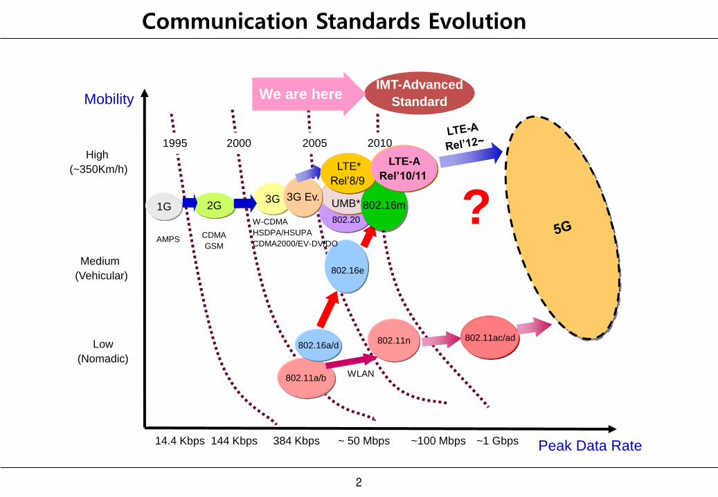
High
(~350Km/h)
Medium
(Vehicular)
Low
(Nomadic)
Peak Data Rate 14.4 Kbps 144 Kbps 384 Kbps ~ 50 Mbps ~100 Mbps
CDMA
GSM AMPS
W-CDMA
HSDPA/HSUPA
CDMA2000/EV-DV/DO
1995 2000 2005 2010
802.16e
802.11a/b
802.16a/d
Mobility
3G
802.11n
IMT-Advanced
Standard
~1 Gbps
3G Ev.
WLAN
802.11ac/ad
We are here
802.16m ? LTE*
Rel’8/9
LTE-A
Rel’10/11
Communication Standards Evolution
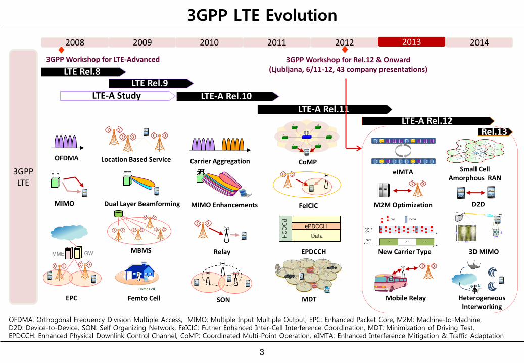
3GPP LTE Evolution
OFDMA: Orthogonal Frequency Division Multiple Access, MIMO: Multiple Input Multiple Output, EPC: Enhanced Packet Core, M2M: Machine-to-Machine, D2D: Device-to-Device, SON: Self Organizing Network, FeICIC: Futher Enhanced Inter-Cell Interference Coordination, MDT: Minimization of Driving Test, EPDCCH: Enhanced Physical Downlink Control Channel, CoMP: Coordinated Multi-Point Operation, eIMTA: Enhanced Interference Mitigation & Traffic Adaptation
3GPP LTE
2013 2011 2012
LTE-A Rel.10
LTE-A Rel.11 LTE-A Rel.12
2014
OFDMA
3GPP Workshop for Rel.12 & Onward (Ljubljana, 6/11-12, 43 company presentations)
Rel.13
2008 2009 2010
LTE Rel.9 LTE Rel.8
LTE-A Study
3GPP Workshop for LTE-Advanced
Dual Layer Beamforming MIMO Enhancements MIMO
EPC
Location Based Service
MBMS
Femto Cell
Carrier Aggregation
SON
Relay
MDT
CoMP
D S U U U D S U U U
D S U D S U D D D D
eIMTA
M2M Optimization
New Carrier Type
Mobile Relay
Small Cell Amorphous RAN
D2D
3D MIMO
Heterogeneous Interworking
FeICIC
EPDCCH
Data
ePDCCH
PD
CC
H
GW MME
3
4
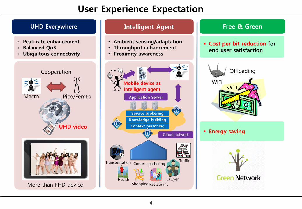
User Experience Expectation
Intelligent Agent Free & Green
Transportation
Mobile device as
intelligent agent
Knowledge building
Service brokering
Context reasoning
Health Shopping Restaurant
Lawyer
Traffic Context gathering
Application Server
Cloud network
Ambient sensing/adaptation Throughput enhancement Proximity awareness
Cost per bit reduction for end user satisfaction
Energy saving
UHD Everywhere
Peak rate enhancement Balanced QoS Ubiquitous connectivity
Macro
WiFi
More than FHD device
UHD video
Cooperation
Pico/Femto
Offloading
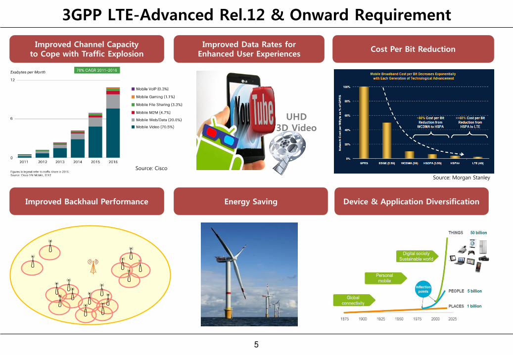
3GPP LTE-Advanced Rel.12 & Onward Requirement
5
Source: Morgan Stanley
Source: Cisco
UHD 3D Video
Improved Channel Capacity to Cope with Traffic Explosion
Improved Data Rates for Enhanced User Experiences
Cost Per Bit Reduction
Improved Backhaul Performance Energy Saving Device & Application Diversification
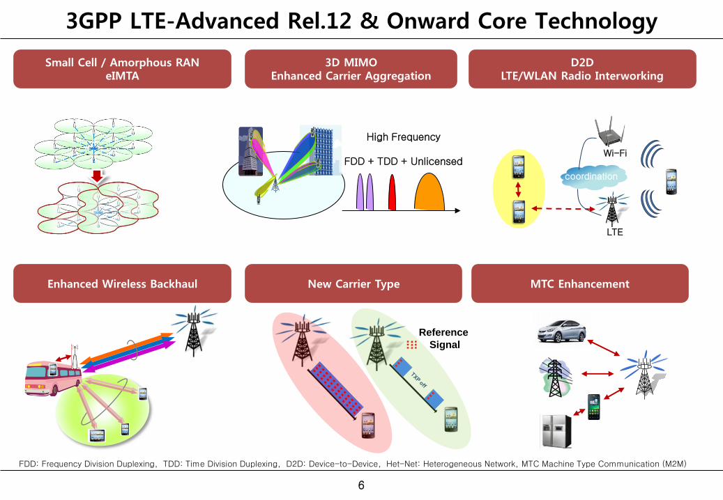
3GPP LTE-Advanced Rel.12 & Onward Core Technology
6
Small Cell / Amorphous RAN eIMTA
3D MIMO Enhanced Carrier Aggregation
D2D LTE/WLAN Radio Interworking
Enhanced Wireless Backhaul New Carrier Type MTC Enhancement
LTE
Wi-Fi
coordination
FDD: Frequency Division Duplexing, TDD: Time Division Duplexing, D2D: Device-to-Device, Het-Net: Heterogeneous Network, MTC Machine Type Communication (M2M)
Reference
Signal
High Frequency
FDD + TDD + Unlicensed
Focus Areas in LTE-Advanced Rel.12~ 1. Small Cell Enhancement 2. 3D MIMO 3. Device-to-Device Communication 4. Enhanced Interference Mitigation and Traffic Adaptation 5. New Carrier Type 6. LTE/WLAN Radio Interworking 7. Other Enhancements
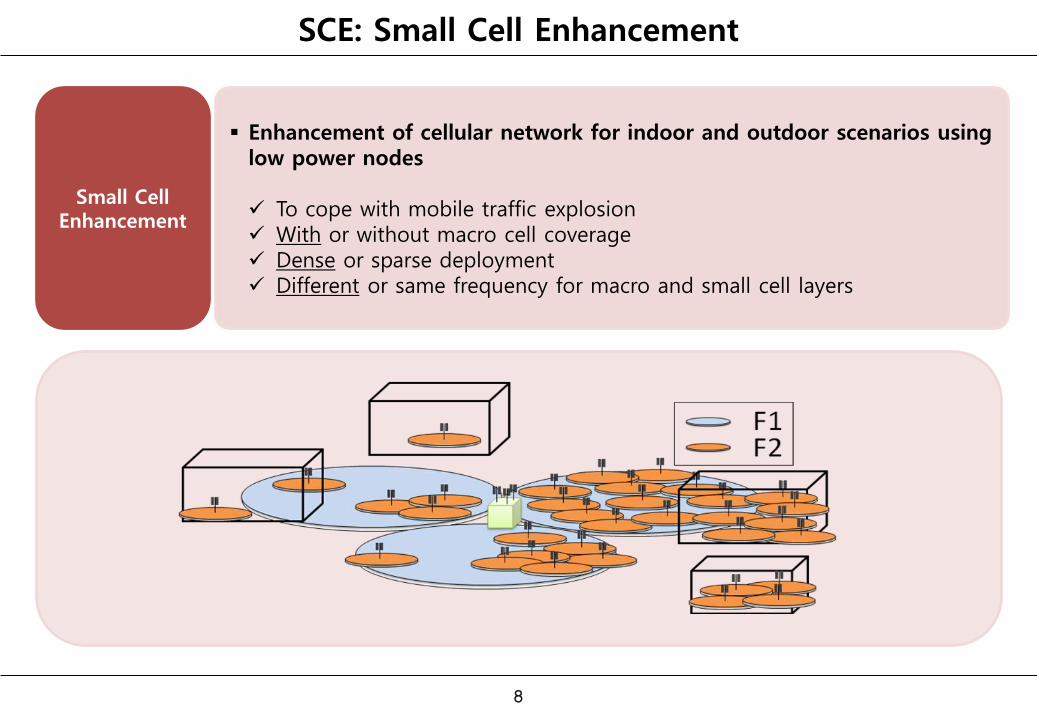
SCE: Small Cell Enhancement
Small Cell Enhancement
Enhancement of cellular network for indoor and outdoor scenarios using low power nodes To cope with mobile traffic explosion With or without macro cell coverage Dense or sparse deployment Different or same frequency for macro and small cell layers
8
SCE : Use Cases
9
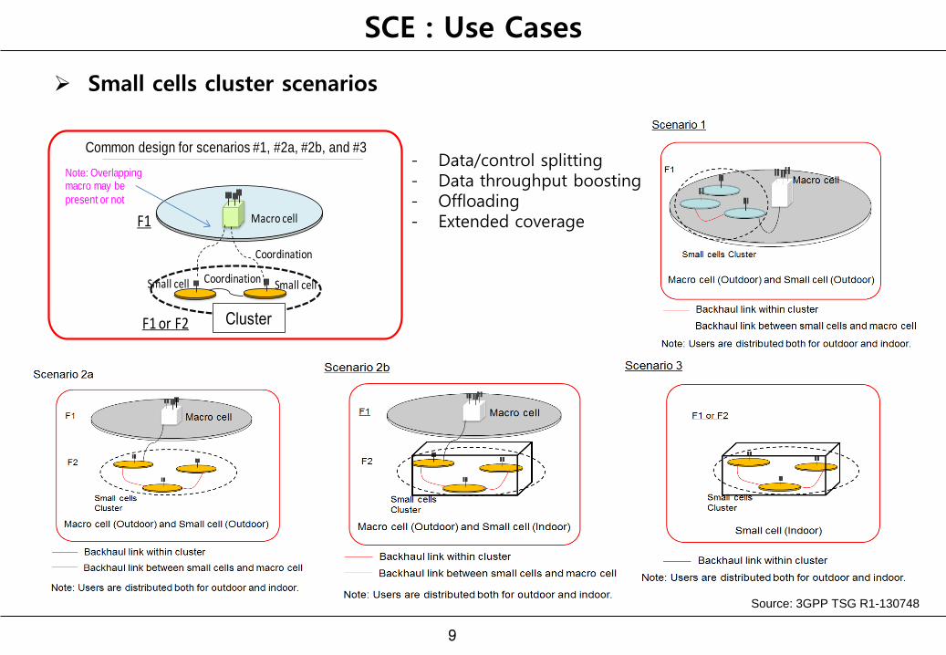
Small cells cluster scenarios
Common solution for scenario #1, #2, #3
Small cell
Macro cell
Small cell
Note: Overlapping macro may be
present or not
Coordination
Coordination
F1
F1 or F2 Cluster
Common design for scenarios #1, #2a, #2b, and #3- Data/control splitting - Data throughput boosting - Offloading - Extended coverage
Source: 3GPP TSG R1-130748
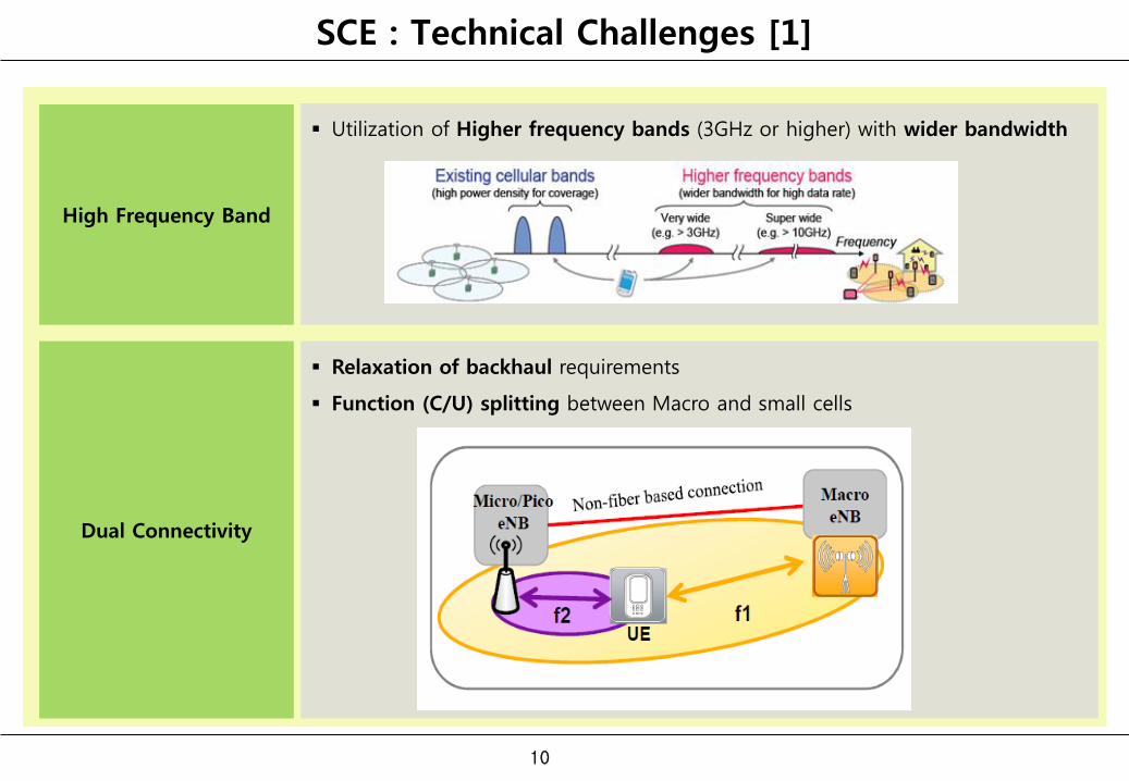
SCE : Technical Challenges [1]
Utilization of Higher frequency bands (3GHz or higher) with wider bandwidth
Dual Connectivity
10
Relaxation of backhaul requirements
Function (C/U) splitting between Macro and small cells
High Frequency Band
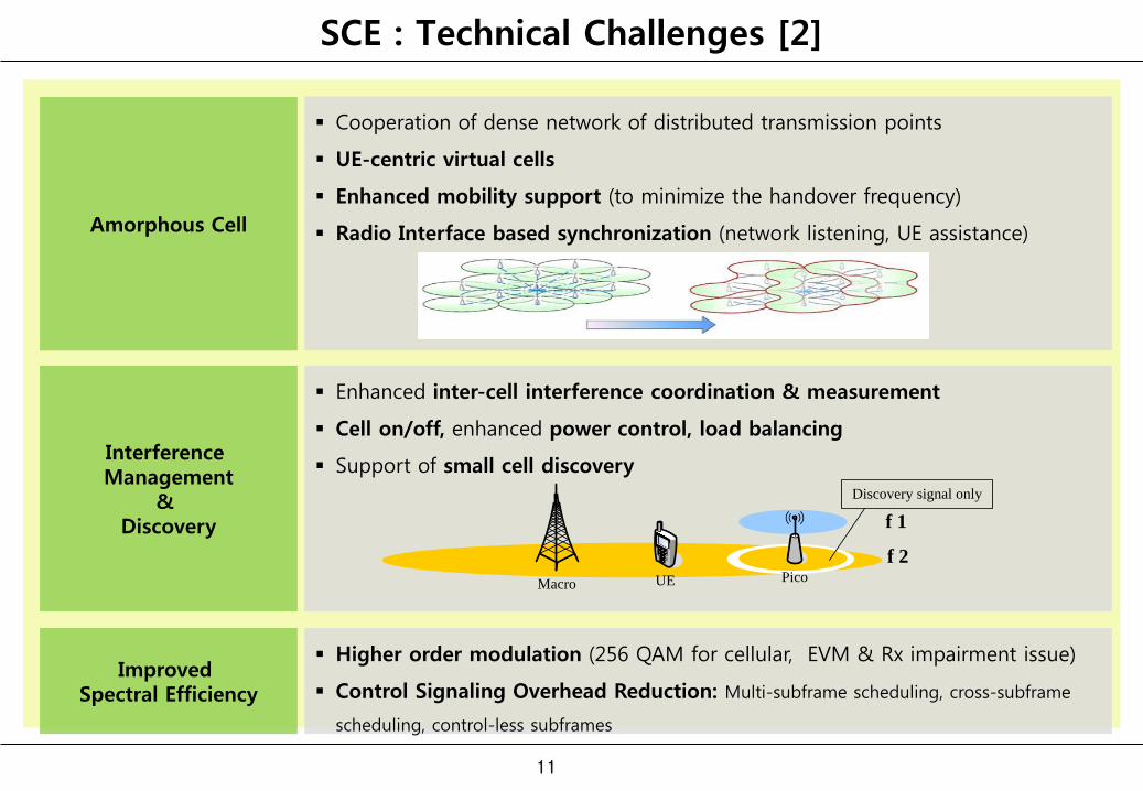
SCE : Technical Challenges [2]
Cooperation of dense network of distributed transmission points
UE-centric virtual cells
Enhanced mobility support (to minimize the handover frequency)
Radio Interface based synchronization (network listening, UE assistance)
Interference Management
& Discovery
11
Enhanced inter-cell interference coordination & measurement
Cell on/off, enhanced power control, load balancing
Support of small cell discovery
Amorphous Cell
Improved Spectral Efficiency
Higher order modulation (256 QAM for cellular, EVM & Rx impairment issue)
Control Signaling Overhead Reduction: Multi-subframe scheduling, cross-subframe
scheduling, control-less subframes
PicoMacro UE
f 1
f 2
Discovery signal only
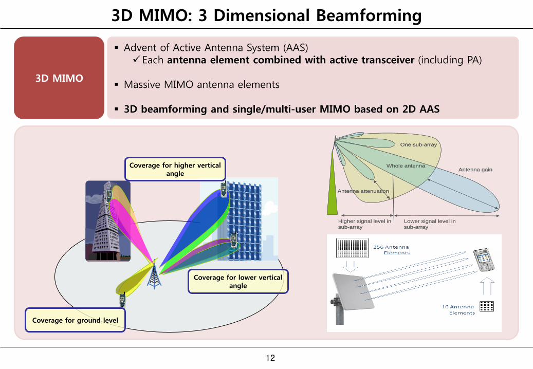
3D MIMO: 3 Dimensional Beamforming
3D MIMO
Advent of Active Antenna System (AAS)
Each antenna element combined with active transceiver (including PA)
Massive MIMO antenna elements
3D beamforming and single/multi-user MIMO based on 2D AAS
12
Coverage for lower vertical angle
Coverage for higher vertical angle
Coverage for ground level
Antenna gain
One sub-array
Whole antenna
Antenna attenuation
Higher signal level in
sub-array
Lower signal level in
sub-array
Antenna gain
One sub-array
Whole antenna
Antenna attenuation
Higher signal level in
sub-array
Lower signal level in
sub-array
13
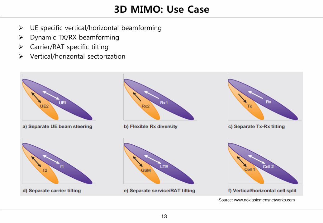
3D MIMO: Use Case
UE specific vertical/horizontal beamforming
Dynamic TX/RX beamforming
Carrier/RAT specific tilting
Vertical/horizontal sectorization
Source: www.nokiasiemensnetworks.com
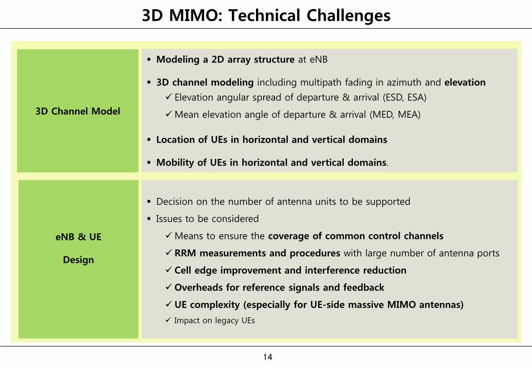
3D MIMO: Technical Challenges
3D Channel Model
Modeling a 2D array structure at eNB
3D channel modeling including multipath fading in azimuth and elevation
Elevation angular spread of departure & arrival (ESD, ESA)
Mean elevation angle of departure & arrival (MED, MEA)
Location of UEs in horizontal and vertical domains
Mobility of UEs in horizontal and vertical domains.
eNB & UE
Design
14
Decision on the number of antenna units to be supported
Issues to be considered
Means to ensure the coverage of common control channels
RRM measurements and procedures with large number of antenna ports
Cell edge improvement and interference reduction
Overheads for reference signals and feedback
UE complexity (especially for UE-side massive MIMO antennas)
Impact on legacy UEs
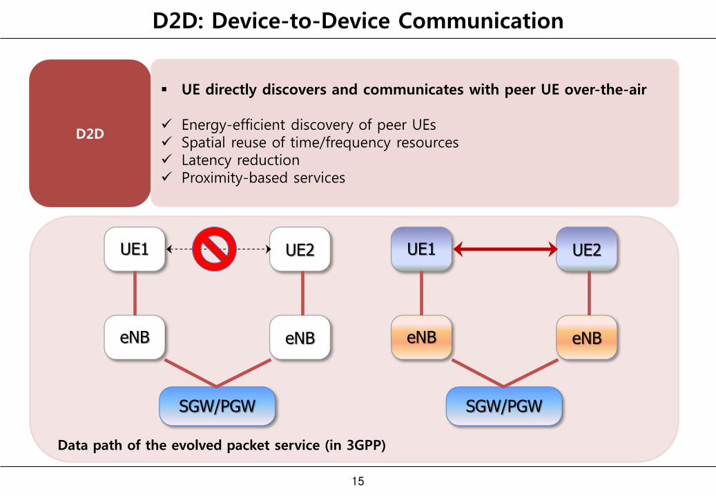
D2D: Device-to-Device Communication
D2D
15
UE directly discovers and communicates with peer UE over-the-air
Energy-efficient discovery of peer UEs Spatial reuse of time/frequency resources Latency reduction Proximity-based services
SGW/PGW
eNB eNB
UE1 UE2
SGW/PGW
eNB eNB
UE1 UE2
Data path of the evolved packet service (in 3GPP)
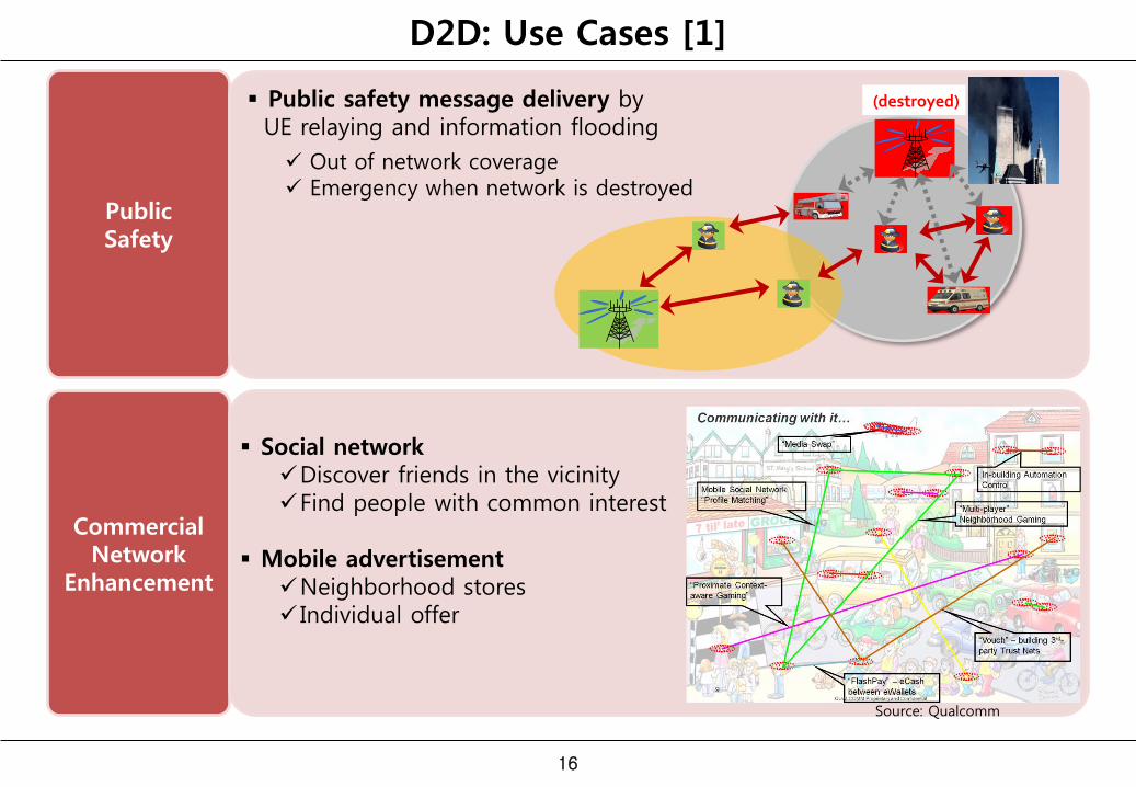
D2D: Use Cases [1]
Public Safety
Public safety message delivery by UE relaying and information flooding
Commercial Network
Enhancement
Out of network coverage Emergency when network is destroyed
Social network Discover friends in the vicinity Find people with common interest
Mobile advertisement
Neighborhood stores Individual offer
Source: Qualcomm
16
(destroyed)
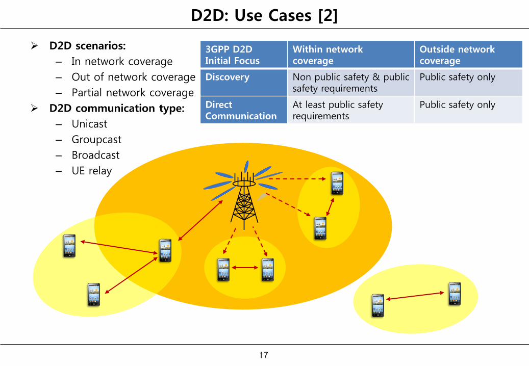
D2D: Use Cases [2]
D2D scenarios:
– In network coverage
– Out of network coverage
– Partial network coverage
D2D communication type:
– Unicast
– Groupcast
– Broadcast
– UE relay
17
3GPP D2D Initial Focus
Within network coverage
Outside network coverage
Discovery Non public safety & public safety requirements
Public safety only
Direct Communication
At least public safety requirements
Public safety only
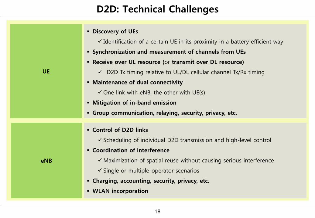
D2D: Technical Challenges
UE
Discovery of UEs
Identification of a certain UE in its proximity in a battery efficient way
Synchronization and measurement of channels from UEs
Receive over UL resource (or transmit over DL resource)
D2D Tx timing relative to UL/DL cellular channel Tx/Rx timing
Maintenance of dual connectivity
One link with eNB, the other with UE(s)
Mitigation of in-band emission
Group communication, relaying, security, privacy, etc.
eNB
18
Control of D2D links
Scheduling of individual D2D transmission and high-level control
Coordination of interference
Maximization of spatial reuse without causing serious interference
Single or multiple-operator scenarios
Charging, accounting, security, privacy, etc.
WLAN incorporation
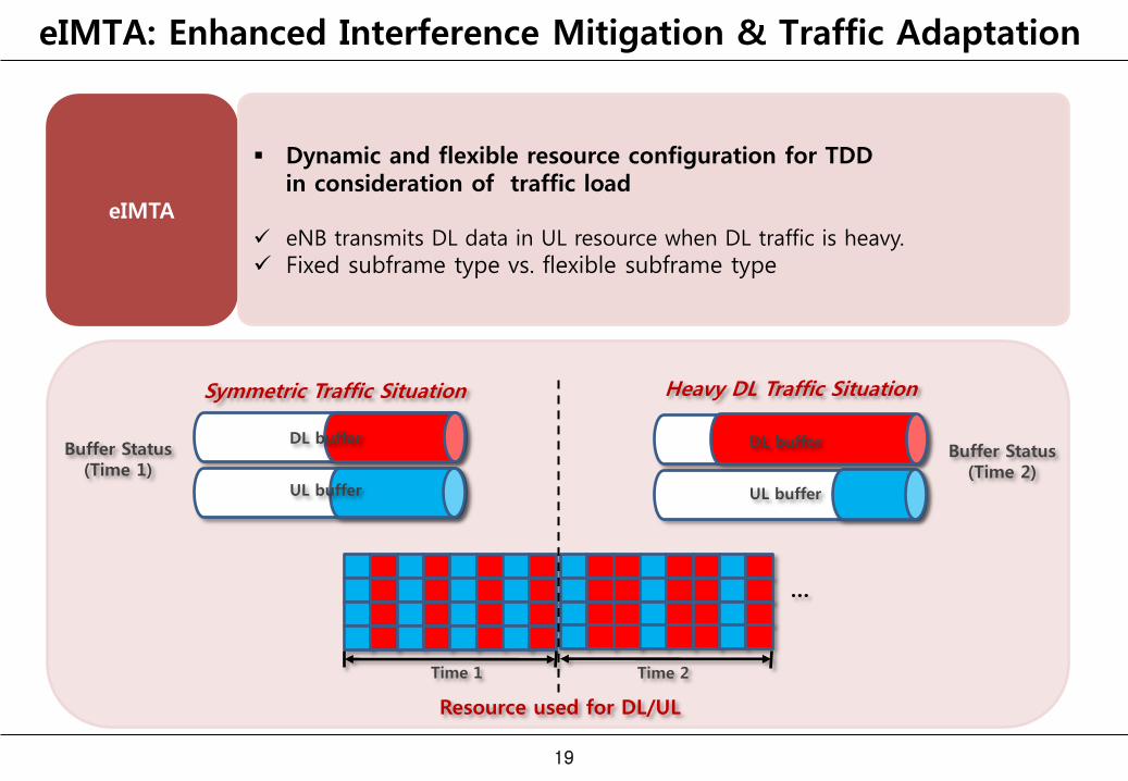
eIMTA: Enhanced Interference Mitigation & Traffic Adaptation
eIMTA
19
Dynamic and flexible resource configuration for TDD in consideration of traffic load eNB transmits DL data in UL resource when DL traffic is heavy.
Fixed subframe type vs. flexible subframe type
Symmetric Traffic Situation
…
Time 1 Time 2
Resource used for DL/UL
Buffer Status (Time 1)
UL traffic
DL buffer
UL buffer
Heavy DL Traffic Situation
UL traffic
DL buffer
UL buffer
Buffer Status (Time 2)
eIMTA: Technical Challenges
Power Control &
Coordinated Scheduling
20
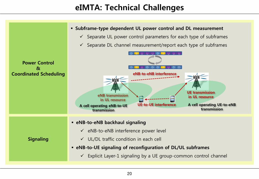
Subframe-type dependent UL power control and DL measurement
Separate UL power control parameters for each type of subframes
Separate DL channel measurement/report each type of subframes
Signaling
eNB-to-eNB backhaul signaling
eNB-to-eNB interference power level
UL/DL traffic condition in each cell
eNB-to-UE signaling of reconfiguration of DL/UL subframes
Explicit Layer-1 signaling by a UE group-common control channel
D S U U U D S U U U
D S U D S U D D D D
eNB transmission in UL resource
A cell operating eNB-to-UE transmission
A cell operating UE-to-eNB transmission
UE transmission in UL resource
eNB-to-eNB interference
UE-to-UE interference
NCT: New Carrier Type
LTE/WLAN Radio
Interworking
21
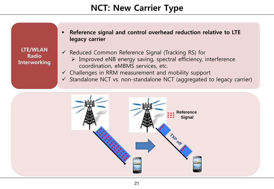
Reference signal and control overhead reduction relative to LTE legacy carrier
Reduced Common Reference Signal (Tracking RS) for Improved eNB energy saving, spectral efficiency, interference
coordination, eMBMS services, etc. Challenges in RRM measurement and mobility support Standalone NCT vs. non-standalone NCT (aggregated to legacy carrier)
Reference
Signal
LTE/WLAN Radio Interworking
LTE/WLAN Radio
Interworking
22
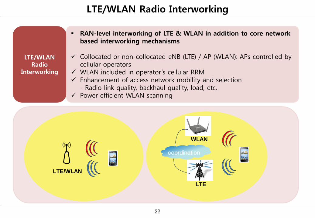
RAN-level interworking of LTE & WLAN in addition to core network based interworking mechanisms
Collocated or non-collocated eNB (LTE) / AP (WLAN): APs controlled by cellular operators
WLAN included in operator’s cellular RRM Enhancement of access network mobility and selection - Radio link quality, backhaul quality, load, etc. Power efficient WLAN scanning
LTE/WLAN
LTE
WLAN
coordination
Other Technologies for Rel. 12 & Onward [1]
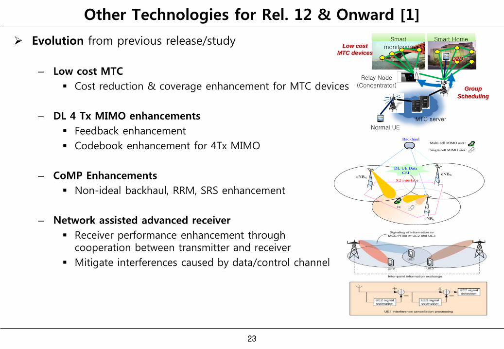
Evolution from previous release/study
– Low cost MTC
Cost reduction & coverage enhancement for MTC devices
– DL 4 Tx MIMO enhancements
Feedback enhancement
Codebook enhancement for 4Tx MIMO
– CoMP Enhancements
Non-ideal backhaul, RRM, SRS enhancement
– Network assisted advanced receiver
Receiver performance enhancement through cooperation between transmitter and receiver
Mitigate interferences caused by data/control channel
23
eNBBeNBA
eNBC
X2 interface
UE
Multi-cell MIMO user :
Single-cell MIMO user :
DL UE Data
CSI
Backhaul
Smart
monitoring
Smart Home
Relay Node
(Concentrator)
MTC server
Normal UE
Low cost
MTC devices
Group
Scheduling
D2D
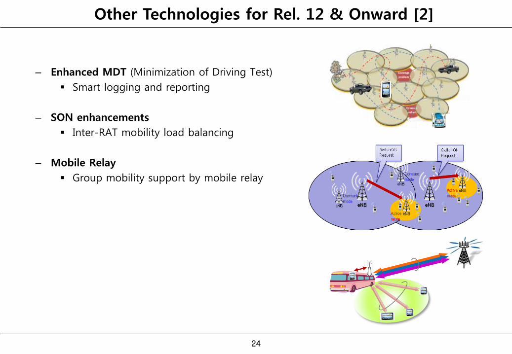
– Enhanced MDT (Minimization of Driving Test)
Smart logging and reporting
– SON enhancements
Inter-RAT mobility load balancing
– Mobile Relay
Group mobility support by mobile relay
24
Other Technologies for Rel. 12 & Onward [2]


![3GPP 5G NR System Design & Verification SolutionA6...3GPP 5G NR System Design & Verification Solution 2 arXiv:1704.02540v1 [csIT] 8 Apr 2017 [ Block diagram of 5G use equipment wireless](https://img.dokumen.tips/doc/110x75/61047f06ecbc7d614d7bccc6/3gpp-5g-nr-system-design-verification-solution-a6-3gpp-5g-nr-system-design.jpg)