Embed Size (px)
Citation preview
I I
_.1 t.
•
•
• • > •
•
•
•
• •
•
EVELEIGH RAILWAY LOCOMOTIVE WORKSHOPS Conservation Plan for The Wheel Press Shop
The Machinery in the Wheel Press Shop The Traverser
•
Report prepared for Commercial Development and Asset Management
Services Branch
February l.994
." .. • • •
•
•
•
•
•
•
•
•
•
~I ___________________ ' ____ O __ O_. ________ ' -
I •
•
I I
• •
I I CONTENTS PAGE
•
EXECUTIVE SUMMARY I'
(I 1.0 INTRODUCTION • I
1.1 Recommendations ••• m ...
I 2.1 The Wheel Press Shop m
2.1.1 Description ••• m
2.1.2 Significance ~ .... m · .,;.
2.1.3 Policy
I m
2.2 Pedestal Cranes ...... 111
2.2.1 Description ...... m •
2.2.2 Significance
~I IV
2.2.3. Policy · , IV
2.2.4 Implementation · IV •
) 2.3 The Wheel Press
I IV
Description •
2.3.1 IV
2.3.2 Significance • IV
2.3.3 Policy V
I 2.3.4 Implementation V
2.4 The Rim Press V •
2.4.1 Description V
2.4.2 Significance V
2.4.3 Policy V
, 2.4.4 Implementation V •
I I1 2.5 The Pipe Bending Press VI
2.5.1 Description •
VI I •
2.5.2 Significance VI •
'I 2.5.3 Policy VI • •
2.5.4 Implementation •
VI
2.6 Doors of the Main Workshops • VI •
-I 2.6.1 Description VI
2.6.2 Significance •
VI
2.6.3 Policy ..
VII
2.6.4 Implementation ..
I ' vu
2.7 Patterns ..
VII
2.7.1 Description ..
VII
2.7.2 Significance ..
I VII
2.7.3 Policy ..
VII
2.7.4 Implementation vii -
2.8 Hoists ••
. Oil· VII
2.8.1 Description •• VII
2.8.2 Significance ..
VII
2.B.3 Recommendation ...
I VIll
•
,I I i -
I I I I I I I I I I I I I I I I I· I •
•
•
•
CONTENTS •
EXECUTIVE SUMMARY 2.9 Oil Tanks
2.9.1 Description 2.9.2 Significance 2.9.3 Recommendations
2.10 The Traverser 2.10.1 Description 2.10.2 Significance 2.10.3 Policy 2.10.4 Implementation
1.0 INTRODUCTION 1.1 Preamble
2.0
1.2 Background' 1.3 Site and Item Identification 1.4 Author Identification 1.5 Methodology 1.6 Documentary Research 1.7 Fieldwork 1.8 limitations 1.9 Acknowledgments 1.10 Report Format
HISTORICAL CONTEXT 2.1 Brief History of Eveleigh Railway Workshops
2.1.1 History and Development 2.1.2 Developments
2.2 Operation of the-Wheel-press Shop and its Plant 2.2.1 Background 2.2.2 Sources . 2.2.3 Operations of the Wheel-press Shop
•
•
2.2.4 Operation of the Wheel-press , 2.2.5 Operation of the Massey Ring Moulder or Flange Press •
2.2.6 Operation of the Pedestal Cranes 2.2.7 Operation of the Pipe-bending Machine
3.0 CONSERVATION POUCY FOR THE WHEEL-PRESS SHOP 3.1 Description
3.1.1 Introduction and Layout 3.1.2 Wall framing . 3.1.3 Roof Framing. 3.1.4 Cladding 3.1.5 External Features of the Services Bridge
•
PAGE
••• V111
" .... Vlll
V111
viii viii ..... ' V111 ... V111
viii viii
1 1 1 4 4 5 5 5 5 6 6
7 7 7 23 23 23 24 25 25 30 30 32
34 34 34 38 38 38 39
•
•

I • • I •
• •
I •
~'
I • • ,
I CONTENTS PAGE
I EXECUTIVE SUMMARY 2.9 Oil Tanks
.. .... Vlll
2.9.1 Description ...
I Vlll
2.9.2 Significance ...
Vlll.
2.9.3 Recommendations ...
Vlll
2.10 The Traverser ...
I Vlll
2.10.1 Description ....
Vlll
2.10.2 Significance ...
Vlll
2.10.3 Policy .......
I Vlll
2.10.4 Implementation ...
Vlll
1.0 INTRODUCTION 1
I 1.1 Preamble 1 • 1.2 Background 1
I. 1.3 Site and Item Identification 4 1.4 Author Identification 4 1.5 Methodology 5 1.6 Documentary Research 5
I 1.7 Fieldwork 5 1.8 Limitations 5 1.9 Acknowledgments 6
I 1.10 Report Format 6
•
2.0 HISTORICAL CONTEXT 7
I 2.1 Brief History of Eveleigh Railway Workshops 7
2.1.1 History and Development 7 •
2.1.2 Developments 23 2.2 Operation of the Wheel-press Shop and its Plant 23
I 2.2.1 Background 23 2.2.2 Sources 24 2.2.3 Operations of the Wheel-press Shop 25
I 2.2.4 Operation of the Wheel-press 25 . •
2.2.5 Operation of the Massey Ring Moulder or Flange Press 30 . .
2.2.6 Operation of the Pedestal Cranes 30
I 2.2.7 Operation of the Pipe-bending Machine 32
3.0 CONSERVATION POUCY FOR THE WHEEL·PRESS SHOP 34
I 3.1 Description 34 3.1.1 Introduction and Layout • 34
3.1.2 Wall framing. 38
I 3.1.3 Roof Framing. 38
3.1.4 Cladding 38
3.1.5 External Features of the Services Bridge 39
I I •
I I I I I I I I I I I I I I I I I I I I I
•
•
• •
CONTENTS
3.0 CONSERVATION POUCY FOR THE WHEEL-PRESS SHOP (CONT'D) 3.2 Documentary Evidence 3.3 Discussion of Significance 3.4 Statement of Significance 3.5 Constraints 3.6 Conservation Policy 3.7 Implementation
4.0 CONSERVATION PLAN FOR THE PEDESTAL CRANES 4.1 Description: Pedestal Crane No 41.
4.1.1 Identification 4.1.2 Description 4.1.3 Detached Components
4.2 Documentary Evidence 4.3 Discussion of Significance 4.4 Statement of Significance 4.5 Constraints 4.6 Conservation Policy 4.7 Implementation
4.7.1 General ,.
4.7.2 Disassembly Instructions andLabelling •
4.7.3 Relocation 4.7.4 Conservation Measures 4.7.5 Reassembly Instructions 4.7.6 Pedestal Crane LC40
5.0 CONSERVATION PLAN FOR THE WHEEL-PRESS 5.1 Description
5.1.1 Identification 5.1.2 Description 5.1.3 Missing or Detached Components
5.2 Documentary Evidence -5.3 Discussion of Significance 5.4 Statement of Cultural Significance 5.5 Constraints 5.6 Conservation Policy 5.7 Implementation
5.7.1 General 5.7.2 Disassembly Instructions andLilbeliing 5.3 Relocation 5.7.4 Conservation Measures 5.7.5 Reassembly Instructions
,
•
PAGE
34 39 40 42 43 44 45
46 46 46 46 50 50 51 51 52 53 • 54
,
54 55 57 57 58 58
60 60 60 60 63 63 • •
.63 64 • 64 65 , 66 I
66 67 68 68 68
-::::-1--:-' --------~------
• • I •
I I
•
I •
CONTENTS PAGE
I 6.0 CONSERVATION PLAN FOR THE RIM-PRESS 69
6.1 Description 69
I 6.1.1 Identification 69 6.1.2 Description 69 6.1.3 Missing Components 71
I 6.2 Documentary Evidence 72
. 6.3 Discussion of Significance 72 6.4 Statement of Cultural Significance 72
I 6.5 Constraints 73 6.6 Conservation Policy 74 6.7 Implementation 74
6.7.1 General 74
I 6.7.2 Disassembly Instructions and Labelling 75 6.7.3 Relocation 75 •
6.7.4 Conservation Measures 75
I 6.7.5 Reassembly Instructions 76
7.0 CONSERVATION PLAN FOR THE PIPE BENDING PRESS 77 • ,
I 7.1 Description 77 7.1.1 Identification 77 7.1.2 Description 77
..
I 7.1.3 Missing Components • 79 7.2 Documentary Evidence 79 7.3 Discussion of Significance 80
I 7.4 Statement of Cultural Significance 80 7.5 Constraints 80 7.6 Conservation Policy 81
I 7.7 Implementation 82
7.7.1 General 82 7.7.2 Disassembly Instructions and Labelling 83
I 7.7.3 Relocation 83 .
7.7.4 Conservation Measures 83 7.7.5 Reassembly Instructions 83
I . 8.0 CONSERVATION PLAN FOR THE DOORS OFTHE MAIN WORKSHOPS • • 84
8.1 Description 84
I 8.1.1 Identification 84 •
8.1.2 Description 84
8.1.3 Missing or Detached Components 84.
I 8.2 Documentary Evidence 85 8.3 Discussion of Significance 85 8.4 Statement of Significance 85
I I
I I I I I I I I I I I I I I I I I I I I
•
•
CONTENTS
8.0 CONSERVATION PLAN FOR THE DOORS OF THE MAIN WORKSHOPS (CONT'D) 8.5 Constraints 8.6 Conservation Policy 8.7 Implementation 9.1 Description
9.1.1 Identification 9.1.2 l)escrijOtion
9.2 Documentary Evidence 9.3 Conservation Policy 9.4 Implementation
10.0 CONSERVATION PLANS FOR HOISTS 10.1 Description
11.0 CONSERVATION POUCY FOR OIL TANKS 11.1 Description
11.1.1 Identification , 11.2 Discussion of Significance 11.3 Recommendations
12.0 CONSERVATION PLAN FORTHETRAVERSER 12.1 Description: The Traverser
12.1.1 Location 12.1.2 l)escrijOtion 12.1.3 Physical Condition
12.2 Documentary Evidence 12.3 Discussion of Significance 12.4 Statement of Cultural Significance 12.5 Constraints . 12.6 Conservation Policy
13.0 BIBUOGRAPHY
•
•
•
PAGE
84 85 85 86 . 88 88 88 88 88 88
89 89
90 90 90 90 90
91 91 91 91 91' 95 95 95 96 96
• 98
•
• •
• ,
•
,
•
I I I I I I I I I I I I I I I
I I I I I
GODDEN MACKAY
EVELEIGH WHEEL PRESS SHOP AND MACHINERY
EXECUTIVE SUMMARY
1.0 INTRODUCTION • This report was prepared for the Commercial Development and Asset Management Services Branch of the Public Works Department as part of the requirements outlined in Conservation Plan Eveleigh prepared by Schwager Brooks Pty Ltd in 1994.
This Executive Summary outlines the findings of this report and indicates the short term and medium term Management Strategies for a range of structures and relics still existing on the Eveleigh site. The buildings, structures and relics addressed in this report are as follows:
The Wheel Press Shop •
The Equipment within the Wheel Press Shop
Cranes The Wheel Press The Rim Press The pipe bending machine The Doors of Bays 1-15 The Patterns The Hoists
The Oil Tanks •
The Traverser
1.1 Recommendations
•
The short term and medium term management strategies for building structures and eqUipment stem directly from the Conservation Plan which was prepared to address each item. •
The Wheel Press Shop The machinery from the Shop should be moved to Bay 4A of the main workshop building. The Wheel Press Shop may be demolished if the site is required for a new purpose. A photographic and architectural recording has been completed for this building.
• I
•

GODDEN MACKAY
The Pedestal Cranes, The Wheel Press, The Rim Press and The Pipe Bending Machine These are recognised as items of significance. They are to be temporarily relocated to Bay 4A of the main workshops where they will be preserved with appropriate conservation and security procedures. in the long term, they will be reconstructed and recommissioned as working relics.
The Doors to Bays 1-15 and The Patterns These were temporarily stored in the Wheel Press Shop for safe keeping. They are to be removed and temporarily stored along with the other machines from the Wheel Press ShOp.
The Hoists and The Oil Tanks These are of insufficient significance to warrant conservation.
The Traverser The traverser is an item that should be conserved in the long term. In the short term, a steel construction is to be built around the cabin and the pantograph tower to be temporarily relocated in Bay 4A, where it may be stored with the items from the Wheel Press Shop.
Brief analysis of each item is provided in the following Section 2.2 to 2.10. For a full description of the items and implementation instructions, the Conservation Plans in the main document should be referred to.
ii
•
I I I I I
I I I I
I I I I I I I I I I

I. I. I. I.
I I I I I I
I I I
•
2. 1 The Wheel Press Shop 2.1.1 Description
GODDEN MACKAY
The Wheel Press Shop is a steel framed, gable rOOfed, corrugated iron clad, purpose built workshop, dating from 1903. The Wheel Press Shop was designed to house the wheel press, a number of cranes and a hydraulic chain and cable testing machine.
It was built as one of a group of three buildings on the south side of the rail tracks which run down the south side of the Main Workshops Bays 1-15. The Wheel Press Shop is stilI
. in good structural condition although the corrugated iron sheeting needs replacing. The floor is uneven and has been subject to a series of changes as changes in technology brought out changes to the floor of the shop.
2.1.2 Significance The Wheel Press Shop has been associated with the Eveleigh Railway Workshops for 90 years. The Wheel Press Shop is a rare example of an open fronted steel framed corrugated iron clad building which exhibits unusual construction techniques. The Wheel Press Shop is now one of the early non-masonry buildings which reflects a change in construction technology at Eveleigh during the period of rapid expansion. The significance of the Wheel Press Shop also lies to a great extent in the equipment and machinery that it houses.
2.1.3 Policy The cultural significance of the building is closely associated with the machinery that is contained within it. If the machinery is to be removed, the building would decrease in significance. It would be difficult to conserve the machinery within the building in both the short term and the long term. Such conservation would be difficult and expensive and would isolate the machinery within this building from that which is already stored in Bays 1-4A
Because of the signifiqmce of the machinery it is recommended that the machinery be removed to Bay 4A and should a new purpose for the site on which the Wheel Press Shop now stands be required, then the Wheel Press Shop may be demolished.
The Wheel Press Shop has been adequately recorded both photographically and archi tecturall y.
2.2 Pedestal Cranes 2.2.1 Description The two identical Pedestal Cranes, registered as LC40 and LC41 were installed in 1917 and 1918 respectively.
ill
•
r
GODDEN MACKAY
The cranes each consist of a pedestal supporting a large ring gear and a vertical king post.
Suspended from the king post is the rotatable crane assembly which consists of a horizontal
jib, a vertical mast surrounding the king post, diagonal braces, a counter weight and the
operator's control cabin. Mounted on the crane assembly are three electric motors, drive
chains and rope tackles to enable loads to be hoisted, traversed or slewed.
2.2.2 Significance The Pedestal Cranes with their open gear trains and riveted construction are large and
impressive examples of electrically powered industrial cranes manufactured around the turn
of the century. The cranes are over 70 years old and have served as an integral part of the
operations of the Wheel Press Shop at Eveleigh Railway Workshops.
2.2.3. Policy The cranes have high heritage significance and because of their rarity, both should be
conserved and made secure. As the Wheel Press Shop may be demolished, the management
policy is to temporarily relocate the cranes in Bay 4A of the Main Workshops building,
while the long term policy is to reconstruct the cranes as working relics within the
workshops complex.
2.2.4 Implementation It is recommended that the two Pedestal Cranes be lifted from their present positions and •
removed to temporary storage. It is therefore proposed that both cranes be dismantled down
to a vertical core, consisting of base, king-post, mast and operator's cabin, as detailed in
Section 4.7.2 p. 55 of the Conservation Plan. The cranes and their labelled auxiliary parts
are to be removed to Bay 4A North of the Main Workshop where they are to be laid in a
stable condition on suitably placed bearers. Each component is to be brushed or sprayed
with Shell ENSIS SDS oil and a chain wire fence to be constructed around the components.
2.3 The Wheel Press 2.3.1 Description The Wheel Press manufactured by Fielding & Platt Ltd, consists of upper and lower
horizontal tension bars supported by a reaction post (housing a hydraulic ram) at the
western end and a passive supporting post at the eastern end. An axle supporter and wheel
thrust blocks can be attached at various positions along the tension bars.
2.3.2 Significance The Wheel Press with its massive cast iron and cast steel components is an impressive turn
of the century machine designed to be transported in sections. The Wheel Press is over 90
years old and served in the building that bears its name since its cOmmissioning.
iv
I I I I
I I I I I I I I I I I I I I I I

I. I. I I. I. I I 1 I I I I I I I I I I I
•
2.3.3 Policy
•
GODDEN MACKAY
As the Wheel Press Shop is to be demolished, the wheel press cannot remain in situ. The
short term management strategy is to temporarily relocate the wheel press in an adjacent
building at the Eveleigh Railway Workshop, where it will be preserved with other heritage
equipment and will be subject to periodic maintenance and security procedures. The long
term management strategy is to reconstruct the wheel press as a working relic within the
workshop complex.
2.3.4 Implementation
It is recommended that the ,wheel press be lifted from its present poSition and moved to
temporary storage in Bay 4A of the main workshops building. It is proposed that the press
be removed as a whole, without disassembly ex~ept for the detachment of the hydraulic
tank and the removal of the Wheel Thrust block. The wheel press and its auxiliary parts are
to be removed to Bay 4A north of the Main Workshop and stored on suitably placed beams
in the location shown on Figure 4.4. Each component should be sprayed or painted with
Shell ENSIS SDC and a chain wire fence should be constructed around the components.
2.4 The Rim Press
2.4.1 Description The rim press, manufactured by B & S Massey Ltd, consists of an upright chassis housing a •
drive mechanism and hydraulics and a set of horizontal wheel support arms near floor leveL
The press is fixed by holding down bolts to a foundation near the south wall of the Wheel
Press Shop and its overall dimensions are approximately 1.75m wide, 2.5m long and 1.9m
high.
2.4.2 Significance The rim press is an impressive, representative example of the types of machines which were
manufactured before the First World War and is now a rare example of early railway
technology. The rim press was an integral part of the Wheel Press Shop and has been
associated with the operations of the railway workshops for a number of decades.
2.4.3 Policy The rim press has some heritage Significance and rarity and should be conserved and made
secure. It is accepted that the Wheel Press Shop may be demolished and that the rim press
can not remain in situ. Temporary relocation in an adjacent building is recommended,
where it will be preserved with appropriate conservation and security procedures until
subsequent recommissioning.
2.4.4 Implementation
It is recommended that the rim press be lifted from its present position and moved to
temporary storage. It is proposed that the rim press be moved in 5 main parts, that is,
disassembled into the four wheel support arms and the chassis. The press and the labelled
v
• •
•
GODDEN MACKAY
auxiliary parts are to be removed to Bay 4A north of the Main Workshop and laid on
suitably placed beams. Each component covered with surface rust should be painted with
phosphoric acid and then painted or sprayed with Shell ENSIS SDC. A chain wire fence
should be constructed around all the components of all the machines.
2.5 The Pipe Bending Press
2.5.1 Description The pipe bending press manufactured by Henry Berry and Co. Ltd, consists of a cast ferrous
chassis to which are attached two hydraulic rams and two anvils or reaction blocks. The
overall dimensions are 2.2m wide, 2.6m long and 0.6m high.
2.5.2 Significance The pipe bending press is a representative example of turn of the century railway
engineering design and is now a rare example of a railway workshop machine. The pipe
bending press is over 90 years old and was once an integral part of the operations of the
Coppersmiths Shop and the Eveleigh Railway Workshops.
2.5.3 Policy The pipe bending press has some heritage significance and because of its rarity should be
conserved and made secure. The short term management strategy is for temporary •
relocation in the main Locomotive Workshops building in Bay 4A, where appropriate
maintenance and security procedures will be available. The long term strategy is for
recommissioning of the press as a working relic.
2.5.4 Implementation The pipe bending press and its auxiliary parts are to be lifted from their present location and
stored together in the location shown on the plan in Figure 4.4. No disassembly is required;
the machine should be laid on suitably placed beams in Bay 4A North of the Main
Workshops.
2.6 Doors of the Main Workshops
2.6.1 Description The original doors were constructed as framed double doors to be hung on either side of a.
round headed or semi-circular arched doorway about 3 metres wide and 4.5 metres high of
which there were 14 in the south side of the Main Workshops.
The doors were panelled with diagonally laid tongue and grooved pine with two braces
fitted internally.
2.6.2 Sjgnificance The doors are integral parts of the fabric of the Eveleigh Locomotive Workshops and hence
are of equivalent heritage status when they are composed of original material. Further
discussion is not possible until the doors can be individually inspected.
vi
I I I I I I I I I I I I I I I I I I I I I
TI
·1
I I
I I I I I I I I I I I
GODDEN MACKAY
2.6.3 Policy A Conservation Policy cannot be prepared for the doors until they can be inspected. A short term policy can be given in this report, which is to preserve the doors in th~~r present condition by storing them in the secure surroundings of Bay 4A of the Locomotive
Workshops.
2.6.4 Implementation The doors should be laid on two separate sets of beams to form two stacks. They should be laid in such a way that the door on top remains parallel to the one below.
No doors should be reinstated until each has been inspected, a Conservation Plan prepared for it and maintenance has been carried out.
2. 7 Patterns 2.7.1 Description The timber patterns appear to be core patterns. They are in fair condition although some of them show signs of cracking. They bear railway pattern numbers which now have no meaning as the catalogue cards have been destroyed.
2.7.2 Significance The patterns have some significance as they were associated with the operations of the
workshops.
2.7.3 Policy It is unlikely that the significance of the patterns can ever be proved. However, until such a time that the space is required, these patterns should be stored with the other material
removed from the Wheel Press ShOp.
2.7.4 Implementation There are no specific conservation methods to be applied to these patterns. It is recommended that they be stored either on pallets or on racks which may be specially
constructed for them.
2.8 Hoists . 2.8.1 Description These are two simple jib hoists with horizontal jibs and diagonal stays attached to the
columns on the south side of the workshops.
2.8.2 Significance There are numerous other examples in the same condition scattered through Bay 4A. It is not believed that these items will help with the interpretation of the workshops.
vii
•
•
I _____________________________________ J
2.8.3 Recommendation These items may be scrapped.
2.9 Oil Tanks 2.9.1 Description
GODDEN MACKAY
These are two very large oil reservoirs outside the fonner Potash Shop which are
approximately 7.5 metres high and 1.4 metres in diameter. They are of riveted construction
in three sections. The tanks have been welded to large flanged feet which have in turn been
bolted to a concrete bed.
2.9.2 Significance The oil tanks are interesting artefacts only and their significance lies in the fact that, in its
later stages at least, the managers at Eveleigh were forced to recycle some of their redundant
machinery.
2.9.3 Recommendations The recommendation is that these large receivers be scrapped.
2. 1 0 The Traverser
2.10.1 Description The traverser is a machine which ran on a set of rail tracks perpendicular to a series of
working tracks which can move a locomotive or a piece of rolling stock from one set of
working tracks to another. The traverser ran on six rail lines of about 80 metres in length.
It consists of a driving mechanism housed in the driver's cabin, towards the rear of the
timber decked platform.
2.10.2 Significance The traverser is an early electrically powered relic which is an integral part of the
locomotive workshops. This traverser, or one very like it, has been operating on the set of
traverser tracks for at least 90 years.
2.10.3 Policy The traverser, the traverser trench and associated rail, are heritage items which should be
considered for retention and conservation. Restoration can only be considered in the long
term as the future of this part of the site is not known. The short term policy is to make the
traverser secure and to prevent weathering and corrosion.
2.10.4 Implementation The short term preservation activity will include building of a steel construction around the
cabin and the removal of the pantograph tower to Bay 4A where it may be stored with items
removed from the Wheel Press Shop.
viii
•
I
I
I I I I I I I I I I I I I I I
I
I I I I ·1 I
I I I I I I I I I I I I
•
1.0 INTRODUCTION
1.1 Preamble
•
GODDEN MACKAY
,
•
• •
•
From the time of their construction until their closure in 1988 Eveleigh Railway Workshops were the most important single workshops complex in the State Rail system. When constructed they were the largest and certainly the most advanced workshOps in Australia. They were an indication of the importance of the NSW rail system and the esteem in which the Victorians held their railways.
At the time of their closure in 1988, the workshops contained the finest example~ of large late Victorian industrial buildings in New South Wales. The workshops also contained the most complete set of late 19th and early 20th century light and medium engineering workshop technology in Australia. This collection of equipment was of international heritage signific~nce and there were no known collections of such importance in the United Kingdom, Europe or the United States of America.
This report concerns the building known as the Wheel Press Shop and the equipment assembled in that workshop. The wheel press is one of the last of the corrugated iron clad or non masonry buildings at Eveleigh and the equipment includes one of the most important sets of late 19th and early 20th century collections within the workshops complex. The', report also addresses two large oil tanks and a traverser which are outside the Wheel Press Shop but adjacent to it. These two relics together with the workshop and its equipment represent the last of the items remaining on the site south of the main workshOps buildings.
1.2 Background The City West Urban Strategy has been embodied in the Regional Environmental Plan 26, City West. This plan is to provide a pleanning framework for four precincts. The Regional Environmental Plan for the Ultimo Pyrmont Precinct was gazetted in October, 1992. Amendment No. 1, English Precinct, to REP 26 was gazetted in July, 1993. A number of buildings, pieces of machinery and several structures are identified in the Amendment as Heritage Items. In their Heritage Study of the precinct, Godden Mackay Pty Ltd in 1990 stated that the complex had international significance and that heritage buildings are relics should be conserved. •
The SRA, at the time of writing, are the owners of the land. The area south of the main rail lines are to become the site of the Australian Technology Park. The ATP proposes to adapt the heritage buildings. ,
The Building Better Cities program (BCC) which is a joint Federal/State initiative, is to provide funding to redevelop the Eveleigh Precinct. One of the requirements of the Bce funding is that a Conservation Policy be prepared for the whole precinct.
•
1
• •
•
I I
,I
I
.1 I I
•
I I I I I I I I I I I
,
•
'n
o I· D t~'~ 1 r J~'" I, .
, I,
hH o . .
.~
" 1 •
• •
•
• ~ \
•
j I I
I
I
-- Nt!.l.c']W:'L~S:fO~U~T,~H~lW.~, ~~: ~L~E~S~-.fC~O~V~£,~Ii'~, N~M'iE.f.~'N~T=-.-:./i'~'A~/fL:lW~~~Y S~-· --
LOCOMOTIve WOfi'f(SHOPS eVELE/CI(. - y.;::.~ .. -
" ,I I , J J ,I , " 1 ,
I, r I , ,
•
,
•
...... ~ -: ..... ~ ,
( I
, , ,~ t I I
" , ' I 1\
, t
" " 11
•
" • ., , ~ •• .l
I·
i • \
I I I
• •
•
n
• t
.~------.~---, · 0 0
, j-- ..... - ~
L-[ -.Jp
;---0 • I.
J.. ;...- ; --,
~ ~~ :'. ,
I, ~ .. • • , .
, . , I
t ~,
, I
• I \ 1
•
•
• I, J ., ."
, . , _ .. ---_ .. - --- --- - -- ~ - ---- .. -
--~ ----------- - -,--- - ---.. ----'t- - ----------'"-' '--
.
I ,f
!I
.--___ ' -, --- ,---;-:L[ .:_.:....,.:.;-". :::::::::::;::-,'_1_, b_, ----le] ___ -, • ' r-•
- • •
• ~ ,I • t • ~--- ... ~- ........ ..,..., ,.'-'- --",.---~-,0,.,> '"' _r, I ,.
• f iI' "'~. .,
',' // - • )J ••
"
f - , . --
I, 11:-·' I r I ' _..,__ 1= = ::::.:.~ It J I , I :: .. :·~-=--------=.-:.-rn ~ ~.,-~ 1; ~: ,;.: I ·,~I : ~:I
- - - - -- - --~t:I' .., I1 .11 I' - - - - - - - - - - d I,:, I I' 'r • r l.l- 1.1 ----- ----- -~/" ,."', d 11 ~---- ----- -, 11 I'" "'.. ,'I
, . , •
,--,
____ ~ _____ -,I I1 1~:1 . :' !l ~---- ---- -1',1 '. 11 I' I' 11 I' • ~ _________ -1',/1 IJ " i" II " !'"'--- ---- -1 I \ ", , ,,' . I , It " , ~ ____ ' _____ --i -, I t I' 'l ! t t I 01 d
DD r- ..... -~.-
• • ..--
I1
n
, •
, , I ,
,I q 11 /I 1" " d ,,,1
r:---'-------+-1L
111 , I "1 I, '( 1I 11 • ( , , /
1--- __ :: -- - -- -,,1 1 I ,," /'. ,I ,I ',I-~. 1-: . ,:,-.c.. -- - - - -j-' 1I ' :' It,l 11 ' ..J .J ~ll...t \'.! 1' __ U ____ l l ___ ), __ 1- __ " __ ... ____ ------
__ .1., _____ .)1 __ --1'1-- __ ~t-_
11 (' 11 /1 " 11 'I . " I I - , I'
i"I ' I t
rl I' I I'
I, Il " , . I t, It
! I, I :: ~ I ~ I , ,I , " • I: • - ---
- - - -- -L-'" - - --1--- - - - -__ .:::!:I - -J...-_-_ ~ -::..t::" -'1=::'::' -- - - ..... - - -- - -- - ----p-- - - .... - - - ---1------' ------r------r------ ---- 1-' j,r- r ;, " I' '''~' . ~ _____ -----H / /I _ _ :':" __ = 11 ~----- ---;- . "if -} ---- " 1--- - --. - - --"7: .: I 11 - :::.-:::- III l""---~- -----~-, :'1' - --· 11
f-~:::.-----ll-:--=--::t 1:"1-=---::: :1 ____ ___ ~ • __ • /1 ---- r -----'-- r-'- -- - , 1-_-____ -- __ L t1---_-= :: I-----~----j-- "j---:-- " 1--- -- - - -- 1_ - ---=1 11 >:-- -- ·-----r- -r-:- II~.-
•
n ~ ... , I :
....--
j
I
t
I , I
· l
•
- -- .. - - ..... - --.. - - - - - -- ------ - - - -- - - .. -- - ----- - '" t' - ----- - -- ... _-- _ ... --- ---- -- ---- .... -- ---- - -- -.--- - _ .. . '
~ ----- ------ - -----.--- ... ::-:..-- - -- -..... --- - - -----'" \ ~--· ~, t i ... _...J
~--------- --------...... -t----. -- -,- - - --- ... - ----~ -------------------'"' I--- --------.--------'" • 1----- ------ - ------------------- - ----
I I • (
'. ~:;:::;:::========j------I -------[ t . , __ _ _.L __________ ..... -
, • • • I
1 j
---------,--------'(1 r-"'" ,,1"- ,1'"--
I-____ ..!-_....o.:...... ~ d ; t -.
~ .......
j' ____ J _____ -_.. ::~ _ -----, ... --: I, q I ' ... ___________ ... __ ..; __ ----.. -'! ! 'I,
i I )J...
; J
I _ ~-:.-:-L __ .L -------:=--~
~:;;.-~'I ..
/.1
\...11 •
•
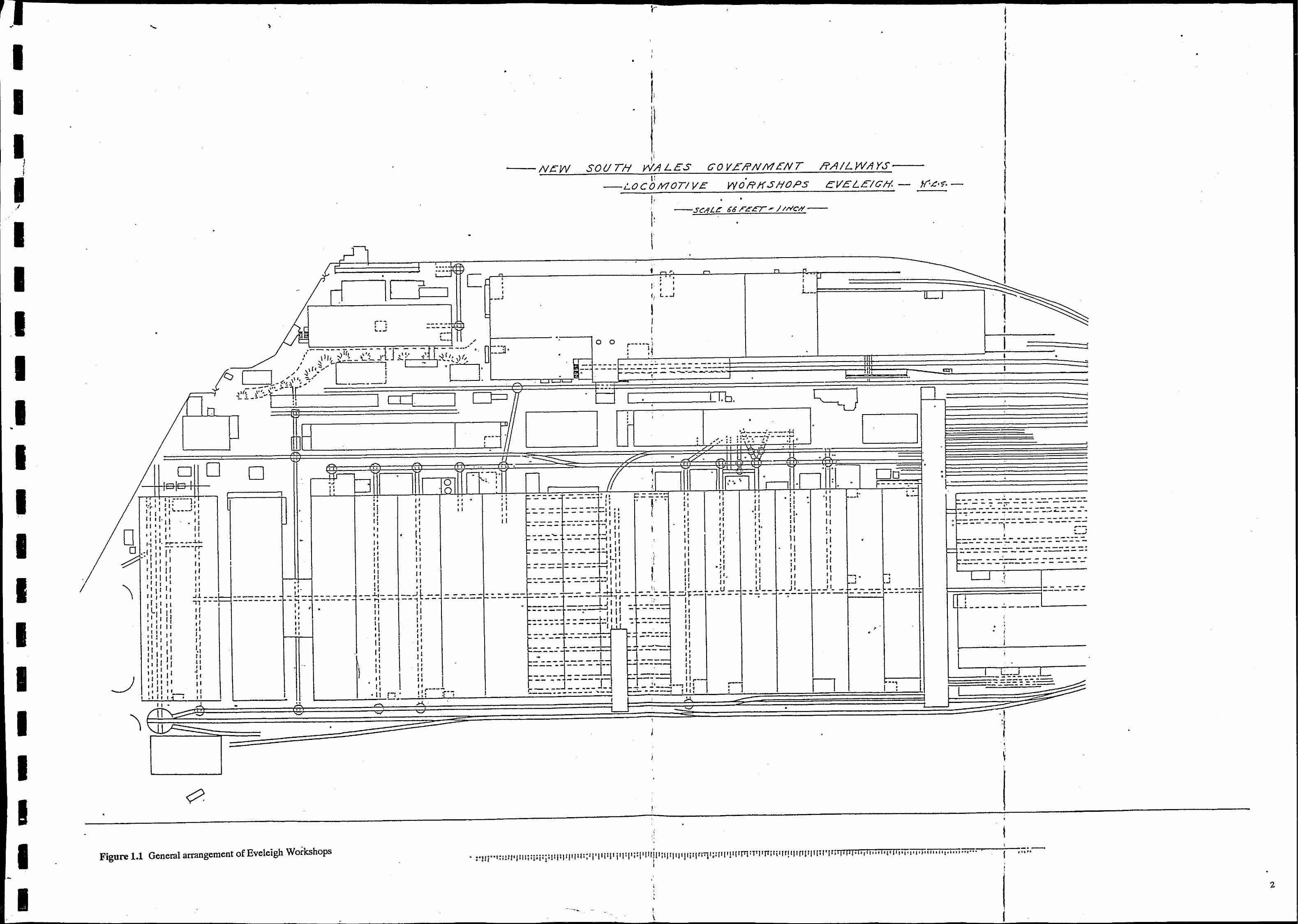
Figure 1.1 General arrangement of Eveleigh Workshops
I
, " ,
•
•
I · -,..,.-_..!--_ ... _ ..
, :'!lju':llIl'lllll Ij,:jl;:ttllP,/I11I :;'1 'I' jl I' i' I: I'i.:! Ifl 'Villi q' I'llill rI'1q:p 1'1 'PP1 q 111rt1li 1lq IJ I [1[lllli/'IWII Ill·! I, ,11' ;"/'1' p,'Toi'i'Ti<"" '11 ,,'" ".,,,. I , .. ..
~-
I
I
\
•
•
•
2


I I I
I I
I I
I I
I
•
,
•
•
GODDEN MACKAY
•
• •
The objectives of the conversation policy was stated in part as
•
•
.. to identify any items within the precinct which are not covered by the heritage provision of the statutory instruments; and
..... to provide guidance for the preparation of individual conservation plans as staged development occurs.
There are a number of items which are not mentioned in the REP but which fall within the Masterplan Areas. These items include the Wheel Press Shop and the relics which are contained in it, the fuel oil tanks and the traverser. The Conservation Policy: states in ,
Section 3.8 that:
Prior to any demolition, relocation or conservation of additional items, a Heritage Report should be prepared which clearly sets out the factors which have been taken into consideration and outlines the reasfJns for the decision taken.
•
This report contains Conservation Plans which address the short term and medium term conservation management of these items. Also covered is the future of the Wheel Press Shop itself which is addressed in Section 3.
•
1.3 Site and Item Identification
• ,
The Wheel Press Shop is located 20 metres south of the main workshops building directly opposite Bays 10-12. The large vertically mounted oil tanks are some 40 metres south of the main workshops, directly opposite Bay 14. The traverser is at the south end of the. traverser tracks some 40 metres south of Bay 15 and some 2 metres west.
The items of machinery, including the wheel press, the two pedestal cranes, the flange press, the wooden patterns, the doors to the workshop Bays 4A-15 and the heavy steel louvre from the former coppersmiths shop as well as the hydraulic pipe bending machine from the coppersmiths shop are all located in the Wheel Press Shop as indicated in Figure 1.2.
• • • •
1.4 Author Identification This report was compiled and written by Don Godden and Christina Kanellakis of Godden Mackay Pty Ltd and Ken Wyatt, Chartered Professional Engineer. Historic photographs and plans were provided by the Archives Section of the State Rail Authority and all photographs were taken by Patrick Grant, Don Godden and Ken Wyatt. Machine drawings are by Christina Kanellakis. •
•
4
•
•
-----------------------------------------------------------------.
I I I I I I I I I I I
I I I I I I
•
1.5 Methodology
GODDEN MACKAY
This report follows the methodology outlined in 1.S. Kerr's The Conservation Plan, the National Trust of Australia (NSW), Third Edition 1991, and complies with the principles of the Australia I CO MOS Charter for the Conservation of Places of Cultural Significance (The Burra Charter and Guidelines).
The terminology used in this report, and particularly the words place, cultural significance, conservation, maintenance, preservation, restoration, reconstruction, adaptation and compatible use follow the definitions provided by the Burra Charter.
1.6 Documentary Research Documentary research was primarily carried out by Christina Kanellakis who made use of the SRA Archives and the collection and material relating to Eveleigh Railway Workshops held by Godden Mackay. Very few photographs, plans and other records relating to the Wheel Press Workshop or the associated equipment was found. The single photograph held by the SRA Archive was undated. Other dated plans of the complex showed the location of the building only and the traverser but gave no details of any equipment to be found inside the Wheel Press Shop. It is believed that no further pertinent documentation pertaining to the Workshop or the material it contains survives.
1.7 Fieldwork The equivalent of the nine and a half person days were spent at the Eveleigh site in measuring the workshops and the associated equipment and in interviewing key informants who had spent their time working at the workshops and within the Wheel Press Shop in particular. The layout of the workshops was recorded in detail by traverse with detailed notes being made of the location of former equipment.
•
1.8 Limitations ,:- ... Documentary research, as indicated above, revealed very little significant information. The age and operations of some of the equipment has been deduced by an examination of the existing fabric, by reference to the general literature on the subject and by interviewing key informants.
This report does not provide detailed plans or drawings of any of the items considered. Photographs have been supplied which indicate the main members of each piece which are mentioned in this report. It iS,believed that sufficient information is provided to allow the implementation of the recommendations of this report.
"
5
-1·····
I I I I I I I I I I I I I I I I I I I
•
•
1.9 Acknowledgments
GODDEN MACKAY
•
•
Valuable assistance in the search for documentary material was again provided efficiently and cheerfully by Victor Poljanski of the State Rail Archives in Transport House, Sydney . Informants who supplied information on site include Guido Governor, Louie Cavalieri, Mr Frank Evans, Maintenance Fitter, Retired; Mr Kevin Skinner, Maintenance Fitter, Retired; Mr Gordon Sim, Millright in the former Spring Shop, since retired; and Mr Steve Swadling, Crane fitter. Mr Jack Bruce, former Supervisor of the Locomotive Workshops also provided valuable information especially concerning the Coppersmiths Shop.
1.10 Report Format This report contains only a brief historical outline of the workshops as this has been dealt with in detail in the report by Don Godden & Associates called the Eveleigh Railway Workshops History and Development 1870-1987, which was part of the larger report called Eveleigh Railway Workshops, unpublished report for the SRA of New South Wales and the National Trust of Australia (NSW). However, a brief chronological history of the • workshops is given followed by the operations of the Wheel Press Shop and its plant. Section 3 contains the Conservation Plan for the Wheel Press Shop and the following, Sections 4-12, contain individual Conservation Plans or policies for the traverser, the oil tanks and the equipment located within the Wheel Press Shop. These polices have been arranged as discrete units and may be repetitive in part. However, each may be used as an individual structure policy.
• '.
•
6
•
•
I I ,
I
, I I I I I I
I I I I I I I I
I
I I
•
• •
GODDEN MACKAY
•
2.0 HISTORICAL CONTEXT
2. 1 Brief History of Eveleigh Railway Workshops
2.1.1 History and Development
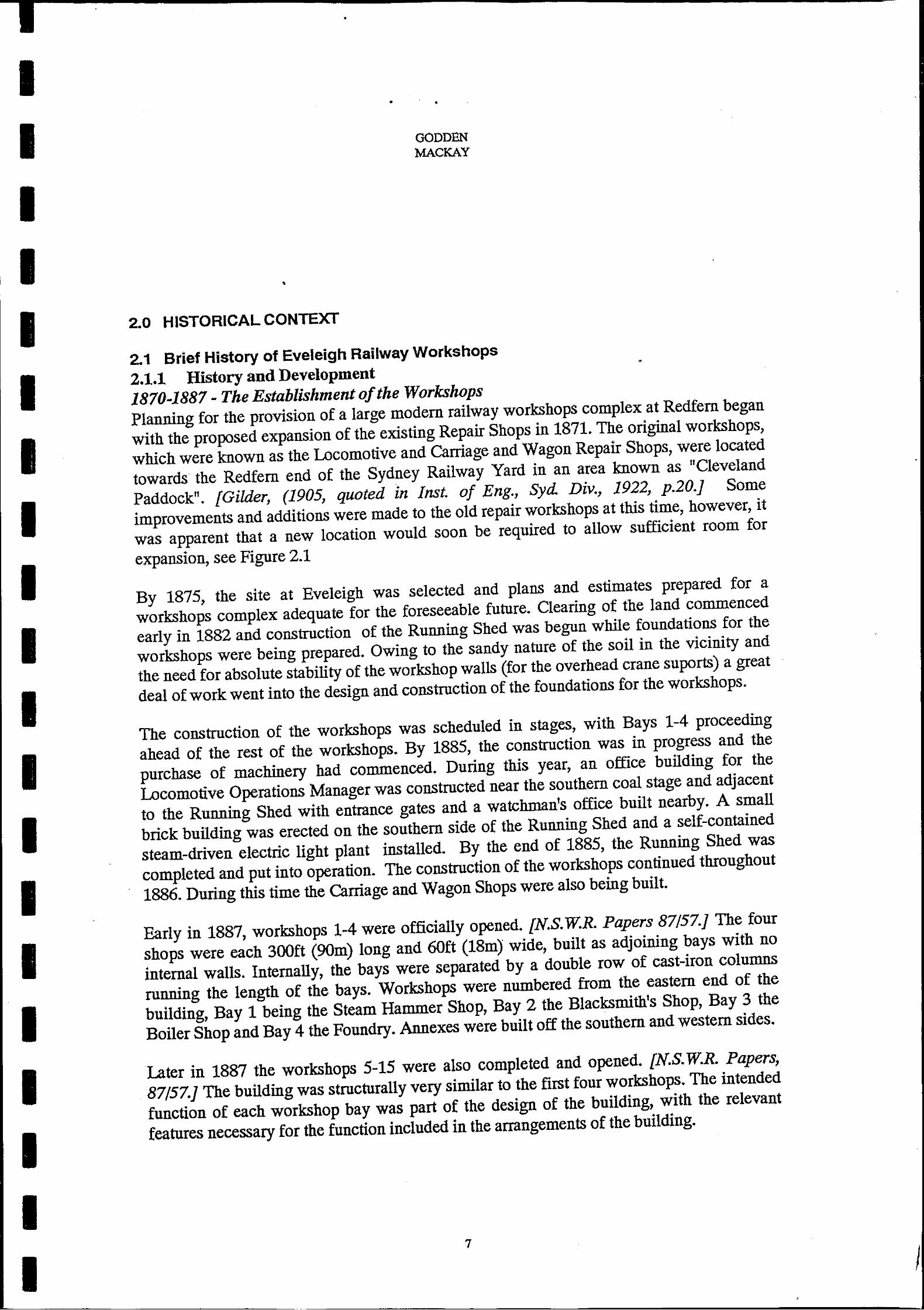
1870-1887 - The Establishment of the Workshops
Planning for the proviSion of a large modem railway workshops complex at Redfern began
with the proposed expansion of the existing Repair Shops in 1871. The original workshops,
which were known as the Locomotive and Carriage and Wagon Repair Shops, were located
towards the Redfern end of the Sydney Railway Yard in an area known as IICleveland
Paddock". [Gilder, (1905, quoted in Inst. of Eng., Syd. Div., 1922, p.20.] Some
improvements and additions were made to the old repair workshops at this time, however, it
was apparent that a new location would soon be required to allow sufficient room for
expansion, see Figure 2.1
By 1875, the site at Eveleigh was selected and plans and estimates prepared for a
workshops complex adequate for the foreseeable future. Clearing of the land commenced
early in 1882 and construction of the Running Shed was begun while foundations for the
workshops were being prepared. Owing to the sandy nature of the soil in the vicinity and
the need for absolute stability of the workshop walls (for the overhead crane suports) a great
deal of work went into the design and construction of the foundations for the workshops.
The construction of the workshops was scheduled in stages, with Bays 1-4 proceeding
ahead of the rest of the workshops. By 1885, the construction was in progress and the
purchase of machinery had commenced. During this year, an office building for the
Locomotive Operations Manager was constructed near the southern coal stage and adjacent
to the Running Shed with entrance gates and a watchman's office built nearby. A small
brick building was erected on the southern side of the Running Shed and a self-contained
steam-driven electric light plant installed. By the end of 1885, the Running Shed was
completed and put into operation. The construction of the workshops continued throughout
1886. During this time the Carriage and Wagon Shops were also being built.
Early in 1887, workshops 1-4 were officially opened. [N.S. w.R. Papers 87157.J The four
shops were each 300ft (90m) long and 60ft (18m) wide, built as adjoining bays with no
internal walls. Internally, the bays were separated by a double row of cast-iron columns
running the length of the bays. Workshops were numbered from the eastern end of the
building, Bay 1 being the Steam Hammer Shop, Bay 2 the Blacksmith's Shop, Bay 3 the
Boiler Shop and Bay 4 the Foundry. Annexes were built off the southern and western sides.
Later in 1887 the workshops 5-15 were also completed and opened. [N.S. w.R. Papers,
87/57.] The building was structurally very similar to the first four workshops. The intended
function of each workshop bay was part of the design of the building, with the relevant
features necessary for the function included in the arrangements of the building.
7
I

I
I
. -
I I I I I I
I
• • • •• ,
ill il _ .. _
• .. --"'C.- ~' ...
-... ---
•
•
I .. ,
• Figure 2.1 The original railway workshops were housed in a collection of sheds around' a two storey store Turning and Pattern Shop. shown in this photograph. The Mortuary Station and Sydney University are apparent in the background.
-
•
8
•
•
• •
• • • • • ,
•
-
•
• • • . ' • • !
! ·1 1
i 1 J 1
I I • L
I I •
I
• •
- -
• : .. .... t. .... j. ., . '. • • , • •
• " •
• • • ,'. · ,~ " . ,
.. ,.., ....... ~ .... .. t. .. ". T .. .. • t .. , .. ,.,
" . . , • • ,
':~
• • . ' . .'
~t • ..
"'-.. --
-
•• , • •
-· -, • • •
• •
-. • _____ • lOO
.,": .. . • •
-
I '
• •
-
. ,.-•
, •
-...... --~ =:t . .:::::l
n.t\ATlON or PUll I
• •
• "
• ,
.,. .... .., .. ... .-"' " ,
• ..
- -
•
• •
.... ',. :-=~ --- -• •
•
• • •
•
. -
J •
• . \ •
"-;;. .... '"
- - -
__ 00' 1--.1
. -,
•• •
'.
•
•
.'
-----~I legioN' .1. L • , , •
•
--C"OSI ateTIOH,,,,tJ--
, .. •
• •
•
• . , • ! ,
• •
• •
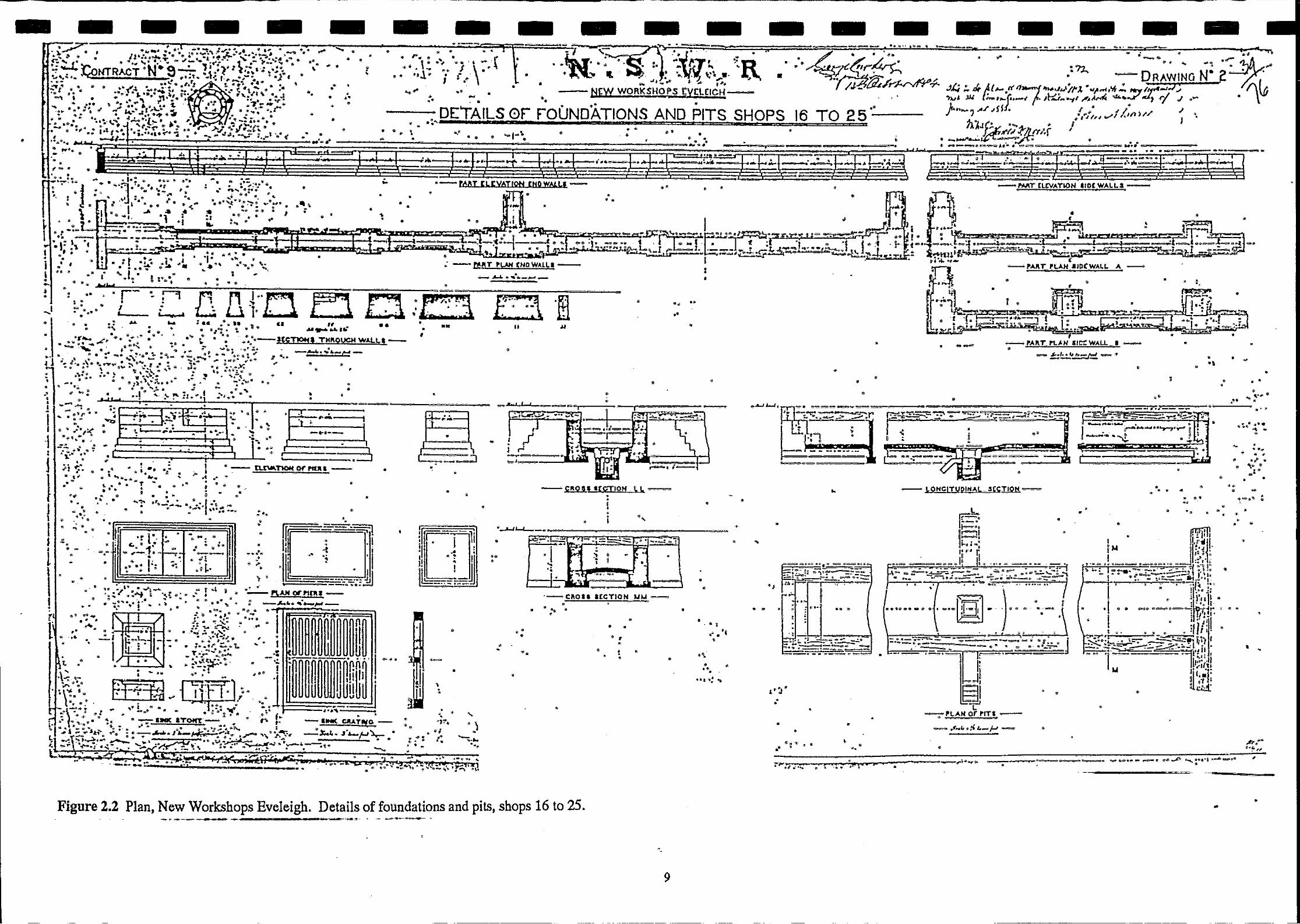
Figure 2.2 Plan, New Workshops Eveleigh. Details of foundations and pits, shops 16 to 25. -~---- - ---- - •
.
9
,
• •
-
•
,
. , of' .. ~, ,
•
• •
- -
"
•
• •
•
• •
•• ". • ••
, , t="~ •• ~:! .'>-::"~.....::.:.~ 1::' .... ---...... --... ... _ -~ ... ,,-.~-------~ .. -.--~~..",
• •
• "',~ '-\)
" ••
, • '.
,
-
•
•
-;" >;'O-'!.* "'''r •• '''. 4 .. ..
•
•
-
- •
- -
• •
•
.-----
•
-
"
• • • •
•
I
• • .. "
.,
-
, •
-
• •
• •
" •
•
• •
_.
• . '
• •
•
•
•
•
I I I I I I I I I I I I
I I I I I I I
•
GODDEN MACI(AY
•
•
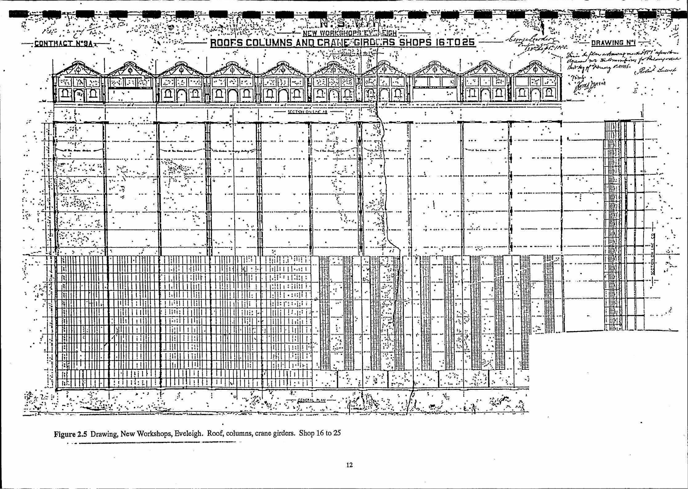
On the northern half of the site, the Carriage and Wagon Workshops also opened late in
1887. Built of the same materials and to an almost identical design as the Locomotive
Workshops, the building comprised ten bays, again 300 ft (90m) long and 60 ft (18m) wide,
numbered 16-25. These shops performed much the same general function as the
Locomotive Workshops but acted exclusively on Carriages and Wagons and from the
outset, new carriages and wagons were constructed at these workshops, see Figure 2.2.
On the eastern side of the Carriage Workshops was built a large Paint Shop for the painting
of carriages. On the ridge above the workshops adjacent to Wilson Street, a large two storey
brick building was erected to house the offices of the chief Mechanical Engineer, under
whose supervision the whole workshops operated.
All the workshops began operations almost as soon as they were completed, such was the
backlog of work created by the inadequacy of the old workshops and the demand created by
the constantly expanding rail system. [Illus. Syd. New, 18/7/91 p.ll.) Approximately 1500
men were employed in the Workshops, under the Chief Mechanical Engineer, Mr W. Thow.
Works Manager of the Locomotive side was Mr H.B: Howe and of the Carriage Side was
MrElson.
1888-1910 - Consolidation and Growth
Following the opening of the Workshops in 1887, the NSW. rail system underwent a
period of sustained growth both in the construction of new lines and the amount of traffic
handled. Although other workshops were established in other locations, Eveleigh was the •
central repair facility for the N.S.W. system throughout this period.
A few major additions appear to have been made to the workshops following its opening. In
1890, a carriage shed was constructed in the south-western corner of the site, adjacent to the
Macdonaldtown Station. In September of 1890 the erection of a timber drying shed was
commenced on the Carriage Side of the Workshops for the storage and seasoning of timber
used in Carriage construction and repair. In 1891, a new coal stage was constructed using
materials salvaged from "the demolition of other earlier coal stages on the site. [N.S. w'R.
Shop Order 1590/252.J A special workshop was established in that year for the
manufacture, maintenance and repair of Signals and Telegraphs in the northern pa~ of the
site. [N.S. w'R. Shop Order 2265/252.J In the western corner of the site, construction of a
gas-producing plant was commenced in November to replace a small plant established
during the construction of the Workshops, [N.S. W.R. Shop Order 2720/253.J •
Construction also commenced on a steam-powered laundry to be housed in a corrugated
iron shed on the southern side of the workshops. [N.S. w'R. Shop Order 2357/252.J It
washed the waste and sponge cloths used for cleaning all over the N.S.W. rail system.
[N.S. w'R. Budget, 21/7/00, p.239-240.J
10
I I I
I I -
I I I I I I I I
•
. • •
•
•
•
•
'~-' . • •
• •
- .
• • •
•
•
,
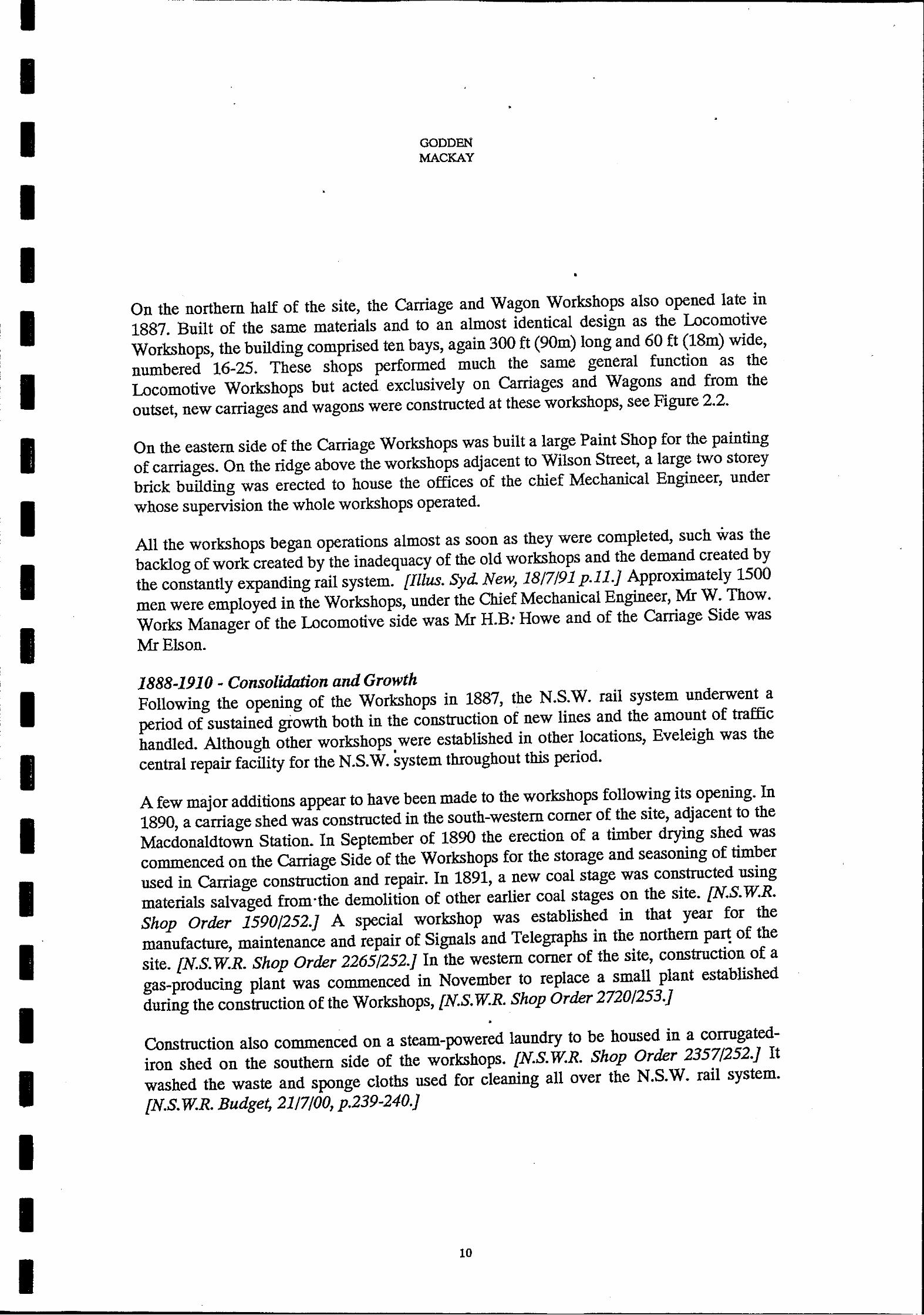
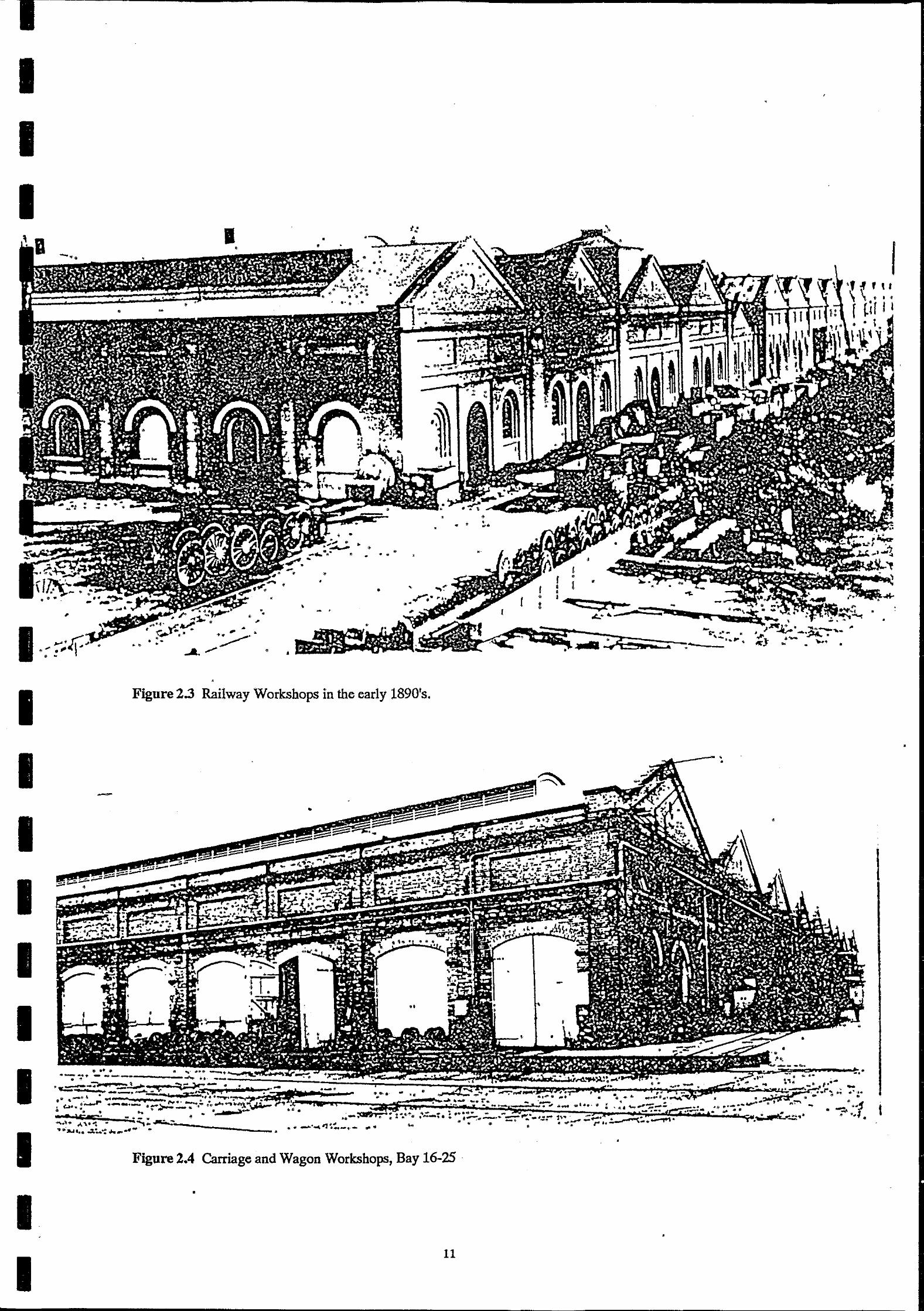
Figure 2.3 Railway Workshops in the early 1890's.
•
~~::~~~~"'!!'~' '" '01 .'~,_ •• ' .: ~ .... "'~ .. ,." -""''''4''~!.._,,_ ..... ,.."
. , •
... .. ' ..
Figure 2.4 Carriage and Wagon Workshops, Bay 16-25
•
11
r I • , , I ........ .
'Pi , L' ~
oL---~
•
• •
•
•
, 'H\ ' 11
\ t, I ~ [ ~i I I1
-
. I ~
•
-'''1 . ... . " •
•
I
I
•
,
• •
•
•
• • • •
• • • . ' .
•
•
•
" ....
,
" "
• , -.
, •
•
•
• •
,
• • :
.' . ,<,.. "
. ' .1r~r-"~ .. ".',..~ .. ~.:,:. .... ",, .. oI'''~~L-..... ." '" ~ ... ~": •...• :., ~·~'-l"IP""=."~ , __ ... c:o" ..
• • • •
• ..,- ...
,
"
... ,..
• • ", · • • • • • , • ... ;;~ -, • •
•
'. •
•
•
•
•
, •
•
... -.. -• • · ., . . . -\.
"
• •
•
•
•
~.
•
• .. • · " •
•
• • • •
. ....
• •
• •
• .. _ ...... •
• -, . ,.
• , . •
" ,', •
" -SO ..
•
•
. " ,
•
•
•
•
-
•
•
• ••
• ,
I , I
.. "'~
. • • . , .. .....
•
• • •
, ,
•
• •
• • .. _-
•• -, ..
• .. ,;
• -" .'
•
,
'.
• • ,
•
• •
•
..... -.. ~ •
_ ...
,
• • \ " --m----I---
•
Il
•
• •
• ,,~ ~ .. ----~ .. •
•
• •
•
• • •
• •
I
,
, • •
•
• - ~"' ... ___ "Ill ..
-,
•
.... -~, '"
.... ~ ....
• ~ ._ ... _____ •.• u:", .... ~.
•
.... , .. ---~~
' .. •
• •
• I
.... -~ ... -...
• • • •
.. • • -. .•.. .:....' .-..
'. ~:. "'* " , . .
• • •
...... ,.~" ....... ~~ •• ( "
.'
.. _ ........
•
.. . •
• ••
, -.~ .
• '" -, •
Figure 2.5 Drawing, New Workshops, Eveleigh. Roof, columns, crane girders. Shop 16 to 25 ... ...................................................................................... . ............ " ............... .
12
•
•
..... -•
.'
• • ,
, .. ..
•
•
@ .. @- .....
.."- ._-• •
• • .,
• , •
•
, •••
•
_ .. ~ ......... -~.III~-"'''-·-· .. .
... ... •
• •
•••
•
•
• • .. .... -
• ,
,
-_ ....... • • •
.. - .. ~ ..... -,
•
•
.,
• •
• ,
•
•
• •
• •
• •
•
•
•
•
.r; :~
f •
•
•
• • ..._. ... .. -.... ~~ 33.' •••••• ,..;·: ..... iitlll ....... •• ...... ---.. •• .. --·II· ...................... -1I.j~~~!I~4.-~i-,,-1i-··"'" •
",'
•
. ..'" .. .. • • •
•
1 , . • .' . • 0, ........ '" ~ .., co,"
...... _ .. ~ 'to!_
"" . •
-•
.. ~_. 0 ..... • •• • ,
• • • ~ .. :~ •
."'. ~
• .~ (~ -J • .. ·.1 '';;'~ . . ...
•
•
•
............ 5 ... "_, .. :,, •
• ,
, • •
•
• •
•
•
•
•
•
• •
•
· •
",
• \
, • •
•
• •
• •
•
\ ,
· .' •
} .. ,
, •
•

I I I I
I
I
I
• •
~ ,
0 ," • • ,. 0 • • ~ . ,
.t-: , • • • ). • . " . ' t • 0 ,
• • '. , • .. • • • .' • l • • , •
~
•
Figure 2.6 Chief Mechanical Engineers Office.
A , . --.= .. '
•
• •
---.,.
• " •
~
~~
• • • •
;.. . •
• •
•
• • ..
•
.' • • • •
• -- • • • •
• • • • • • , ,
• • • #
,. .- -
This building, erected in 1887 as the control centre for both the Locomotive and the Carriage Workshops.
•
13
•
• • • • -..... " • • • •
•
I
I I I I
I I I I I I
I I I
..
•
, .
GODDEN MACKAY
A contemporary description from 18th July, 1891 edition of the Illustrated Sydney News describes the works in detail and claims that in size, scope and in the technology employed, Eveleigh Workshops at this time had no equal either in Australia or the southern hemisphere.
In 1892, union negotiations led to the workshops being closed on Saturdays - this was part of the social change underway at this time that eventually created the two-day weekend that remains a feature of Australian working conditions. [McLachlan, N.S. W.R. Sec. Office 19/3/92.}
In 1898, the first major expansion of workshop facilities occurred with the construction of the new Erecting Shop. See Figure 2.7. Built to increase the accommodation for the repair of locomotives, it soon became known as the Large Erecting Shop to differentiate it from the Erecting Shop occupying Bays 6-8 in the main workshop building. The Large Erecting Shop was situated on the western side of Bay 15 and was completed in June, 1899. [N.S. W.R. Shop Order 28/6/99.}
Concurrently, a new Foundry building was being erected adjacent to the Large Erecting Shop site. [N.S. W.R. Shop Order 2/3/99.J It was established to allow the Boiler Shop to expand in Bay 4 of the main workshops.
Following the establishment of the Large erecting Shop enabling many of the engine repair functions to be removed from the main building, the Paint Shop became immediately redundant and work commenced on converting Bays 12 and 13 for an Interlocking Shop. [N.S. W.R. Budget 21/7/00, p.239-240.}
In 1900, owing to the large amount of locomotive repair work in hand and the expected growth in the area, an extension to the Large Erecting Shop was commenced. [N.S. W. Railway and Tramway Magazine, 12/17, p.37.J This extension was of 200 ft on the western end. It appears that this extension proceeded gradually as the work was not completed till 1906. .
In a seperate development, a compressed-air plant was installed in an annexe to the Boiler Shop (Bays 3 and 4) and air-mains were installed around the workshops. [Fewtel~ F., Works Manager, 14/5/55.} The year.1900 also provid~d an excellent and comprehensive description of both the Locomotive Workshops and the Carriage and Wagon Workshops in the monthly journal known as the N.S.W. Railway Budget. The Locomotive Workshops were detailed in the July 21 issue and the Carriage and Wagon Shops in the following issue of August 21.
•
14
•

I I I I I
•
I 'i
I I I I I I I
•
• • • ••
•
•
.' I
", 1 " •
•
,
•
' ........
I' \ : \
Figure2.7 Loco Workshops, Large Erecting Shop. Constructed in 1899 and extended progressively until 1906, it was the centre of the locomotive repair operations at Eveleigh.
•
15
..- - -=-
I I I I I I I I I I I I I I I I I I
GODDEN MACKAY
Two new structures were commenced at the end of 1902. [N.S. W.R. Shop Order 1112102.J A new Copper and Tinsmiths Shop was established in a shed on the southern side of Bays 5-9, the former shop in the laneway between Bays 4 and 5 being demolished shortly afterward. [N.S. W.R. Shop Order 1/12/02.J A large building of corrugated-iron was erected on the eastern end of the workshops (outside Bay 1) which contained in its northern half a Spring Shop and in its southern half a Steam Hammer Shop. The reason for these two constructions was the need to expand the operations of both the Blacksmiths Shop (Bay 2) and the Boiler Shop (Bays 3 and 4).
. Although the exact date is unclear, it appears that the Wheel Press Shop was also established at this time adjacent to the new Tinsmiths Shop. Housed in a corrugatediron/clad, steel framed shed to the south of Bays 10-12, this shop contained hydraulic presses for removing axle centers, a tyre-heating plant, hydraulic cranes and a chain-testing machine. [Inst. of Eng. Syd. Div. 11/10122.J
The year 1907 was distinguished by the decision of the Commissioners for Railways to begin the manufacture of new locomotives at Eveleigh and a new building was designed for this purpose. Clearing of ground on the eastern end of the workshops complex commenced in September and construction began shortly afterwards of the new Loco Shop. [Fewtel~ F., Works' Manager, 14/5/55.J Also during 1907 a new compressor house was established on the south side of the New Loco Shop site.
The following two years saw the refurbishment or replacement of many of the operating boilers around the workshops. [N.S. W.R Shop Order, 2815/08.J
Most overhead cranes in the workshops were all converted to electric drives by 1902. A significant development in 1910 was the construction of indoor toilet facilities throughout the workshops - the result of labour negotiations for improved conditions .
•
In contrast to the almost constant development in the Locomotive Workshops during the two decades 1890-1910, operations in the Carriage and Wagon Workshops appear to have proceeded with few major changes or alterations to either the buildings or equipment. [N.S. W.R Shop Order, 31/1/01 and Shop Order, 7/11101.J In 1907, a new building was erected on the northern side of the workshops to house the Wagon and Carriage Blacksmiths Shop. [N.S. W.R Shop Order, 29110107.J Apart from minor changes, work on the maintenance and repair of the Railways rolling stock was carried on uninterrupted and new carriages were being constructed at the rate of about ten per week.
16
•
I I I I
I I I I
I I
>
I I I I I I I
1910-1935 - War, Peace and Recession
GODDEN MACKAY
The years 1911 to 1913 were quiet years for the Workshops. A Grinding and File Making
Shop was established in the old Cleaning Annexe behind Bay 9 during 1911, it provided a
central facility in the Workshops for tool maintenance and repair. [Fewtell, F., Works
Manager, 14/5/55.J In 1912 a Sigrial and Telegraph Branch Workshop was constructed in
the north-eastern corner of the workshops site, adjacent to the Redfern Station No. 1
Platform. [NS. W.R. Shop Order 228/256.J
<
The Carriage and Wagon Paint Shop was extended around this time and the area on the
western side of the Carriage Repair Shed, known as the Carriage Shop Paddock, was roofed
over the additional car repair space. [NS. W.R Shop Order 228/256.J The Paint Shop
extension was built on the northern side of the existing shed. [NS. W.R. Shop Order 24/8/12
and Shop Order 19/9/13J In 1913 a footbridge was built across the southern end of the yard
for the workmen to cross the tracks more safely. [ N.S. W.R. Shop Order 256/187.J
The beginning of 1914 and presumably the outbreak of war in Europe gave impetus to a
significant upgrading of facilities and rearrangement of workshops. The New Loco Shop,
constructed in 1907, was extended on its southern end by 100 ft (30m) to a total of 300 ft
(SOm), making it equivalent in length to the Main Workshops. [N.S.W.R. Shop Order
11/5/14.J
Electrification of machinery in the workshops was another major undertaking, with No. 14
Bay (Pattern ShOp) electrified by the Sth of January, No. S Bay (Erecting Shop) and No. 9
Bay (Machine Shop) completed by the beginning of August. >
In order to allow an expansion of the Machine Shop, the Laundry was removed from the
building adjacent to the Large Erecting Shop and re-established in a new building at Clyde
where it still remains, known as the Clyde Laundry. The Millwrights Section and the Water
Supply Section then moved from No. 11 Bay to the former Laundry building and the No.
11 Bay become part of t~e. Machine ShOp. [Fewtell, F., Works Manager, 14/5/55.J This
was a temporary arrangement while the Machine Shop was reorganised.
On the Carriage side of the Workshops, a large two-storey stores building was constructed
west of the timber shed in the Stores Branch complex. [NS. w.R. Shop Order 257/38.J The
other stores buildings were less substantial timber and corrugated-iron buildings, built at
various times since the establishment of the Workshops, all administered by the Railways
Stores Branch. The new building rationalised much of the Stores Branch's activities under
one roof in the centre of this area. See Figure 2.S
Following the rearrangement of the Machine Shop, the Millwrights moved into a section of
No. 9 Bay. The Water Supply section, concerned with the supply of all taps, pipes,
connections, tanks and other material concerned with the provision and use of water in the
railways, also moved out of the former Laundry to a new workshop at Erskineville and the
laundry building was subsequently demolished. • <
17

I • •
I I I I •
I
- • • • -• •
• • ~~
• • • .. • •
• • •
•
I •
I •
I ..
~ • • .-'. ., I • , . '. " • I
• • • ~ • • I
I Figure 2.8 Carriage Workshops - Stores Building This bulding was constructed to rationalise the existing stores facilities which had been housed in a collection
of Air Sheds in this area. ."
I I I
18

I
I I I I I I I I I . 1 I I I I I I I I I
'-------------------------------------------,
GODDEN MACKAY
, .
During 1916 as part of the war effort at this time, a trial production run of 5,000 18lb fieldgun shells was made in the workshops using machines modified for the purpose. [Fewtell, F., Works Manager, 14/5/55.} This was discontinued because the machines were on the whole inappropriate and the whole arrangement judged to be unsatisfactory for both the Army and the Railways.
In 1917, a new Foundry building and a new Pattern Shop building were constructed on the southern side of the workshops. This required a resumption of two acres of land on the south-western end of the site to allow a rail siding to be built to connect to these two new structures. [N.S. W.R. Shop Orders 258/272, 40/254 and 2160/259.J
Sometime prior to 1917, a Potash Washing Plant was established in a small corrugated-iron ,
shed between Bay 15 and the site of a new Foundry. Containing large Potash tanks served by a hand-operated overhead crane, it was used to wash the grease and dirt from detail parts of locomotives. [N.S. W.Railway and Tramway Magazine, 12/17, p.37.J With the completion of the new buildings and the transfer of operations from the workshop building, the remaining shops were rearranged and rationalised .
The Steel Foundry section of the new foundry was opened in 1919 using an oil-fired Stock Steel Converter as its main furnace. [Inst. of Eng. Syd. Div. 11/10/22.J By 1922, it was deemed necessary to have an electric furnace for this section and a major extension of the Steel Foundry was undertaken for this purpose. Added on to the western end of the Foundry building, the extension and furnace installation was completed by November, 1923. [N.S. W.R. Shop Order 437/260.}
In 1923, a major portion of the boiler repair work was shifted to a new facility established at Chullora. In 1925, the No. 1 Blacksmiths Shop in Bay 1 was completely rearranged and a 1500 ton steam-driven "Davy" press was installed in the northern side. [Fewtell, F., Works Manager, 14/5/55.}
The quadruplication of the Illawarra Line in 1925 brought, as an initial step, the demolition of the northern bay of the Running Shed to provide more room in the yard for these lines. [Wylie, 1963, in A.R.H.S. Bulletin 291-314, p.945.} Also in 1925, construction commenced on an elevated timber coal stage on the northern side of the workshops, a 40,000 gallon water tank was erected on high ground near Cornwallis Street and plans were approved and construction commenced on a subway under the main yard. The subway was completed in July 1927. [E.W.C.S.C., 1968 in EveleighNews No. 377.}
As these works were underway, elsewhere in the works the mounting pressure on Locomotive repair facilities led to, in 1925, the decision to cease the manufacture of new
. locomotives at Eveleigh. [Fewten F., Works Manager, 14/5/55.J The New Loco Shop was from this time used largely for locomotive repair work. Up to this time, one hundred and fifty-three locomotives had been constructed at EveJeigh.
19 •

I I
I
I
I I I I I I I I I I I
I •
GODDEN MACKAY
By the end of the year, a new Tinsmiths and Plumbers Shop had been built on the bank above the Pattern Shop. The former Tinsmiths Shop adjacent to the Wheel-Press House was subsequently converted to a Welding Shop, welders having previously been housed in several different areas.
In February of 1928, two new Traversers were installed in the Large Erecting Shop. This appears to be the last new building or purchase of new equipment that occurred in the workshops until 1935, the period of the Great Depression. Apart from this lack of growth, the Workshops appear to have managed through the difficult times without major setbacks.
The equivalent period 1910-1935 brought far less activity and development in the Carriage and Wagon Workshops than for the Lococmotive Workshops. 1913 saw extensions to the Paint Shop and the Carriage Repair yards, with the construction of the large stores building in 1914. The Traverser between the Paint Shop and the Wagon Shop was extended in 1915 and two 25 ton T.Goodall and Co. electric overhead cranes were installed in 1920. [N.S. W.R. Shop Order 21/6/15.J A number of buildings came into existence in the Carriage Workshops area that were erected between 1914 and 1924. They were a Materials Testing Laboratory, two stores and general workshops, a brick residence near the stores buildings and an oil storage shed.
1935-1970 From Excellence to Obsolescence By 1935, the Eveleigh Workshops had grown into a solid and mature operation, with its role within the Railway's system established and complete. Eveleigh was the central Locomotive and Carriage and Wagon Repair facility as well as handling most of the heavy forging and parts casting for the system. Technology brought in with the twentieth century, electricity and steel for example, had been embraced and adopted where appropriate and the interrelationships between various departments and shops were well established.· The improvements made during the early 1920's were obviously sufficient to carry the works through the Depression without mishaps or problems .
•
The lack of development at Eveleigh during the 1930's was related to the development of other Workshops in the system - with Eveleigh established and running smoothly, new constructions and developments in other departments could be undertaken at the other Workshops. In 1937, the opening of a new large locomotive repair depot at the Chullora Workshops enabled much of the repair work to be removed from Eveleigh and the Old Erecting Shop located in Bays 5 and 6 was vacated later in the year. [Fewtel~ F., Works
. Manager, 14/5/55.J
With the outbreak of war in Europe, negotiations between the Department of Defence and the Railways Department were initiated again as all heavy engineering shops throughout the country were pressed to assist in the manufacture of military equipment. The lessons of the First World War experiment had been learned and in early 1940, Bays 5 and 6 were cleared of machinery and plans drawn up for the installation of equipment supplied by the Department of Defence for the manufacture of 25lb field-gun shells. [Fewtel~ F., Works Manager,14/5/55.J Another contribution to the war effort was the manufacture of the
20
,
•
I I I I I I I I I I I I I I I
I I I I
•
GODDEN MACKAY
,
special tools required in the manufacture of Bren Guns. Although the guns were manufactured in Defence Department factories, the whole of the machinery required was manufactured in the Machine Shop at Eveleigh. These arrangements were in general a temporary solution while the Defence Department organised its own factories.
On the Carriage Workshops side, the war saw the building of several temporary barrackstype accommodation buildings and the conversion of the large brick stores building to a hostel for the accommodation of transient railway employees and Defence Department workers. A canteen building and kitchen were constructed adjacent to the hostel. The stores residence was used during this period as the Hostel and Canteen Supervisors Residence.
About 1942/43, concrete air-raid shelters were erected in various locations around the Workshops, generally agains~ embankments or in sheltered corners of the site.
During 1944, plans were drawn up and construction commenced on a major extension of the Works Managers Office, transforming it into a much larger building. [Plans: N.S. W.R. Ways and Works Branch No's. 102/144 to 102/146, 23/3/44.] At the same time a larger addition was erected on the southern side of the Foundry to house new staff amenities for the foundry staff. [Plan: N.S. W.R. Ways and Works Branch No. 975/34.215, 8/12/43.J
With the end of the war in 1945, the production of 251b field gun shells in Bay 5 ceased and the machinery, owned by the Defence Department, was removed soon afterwards. The Workshops settled back into their normal routines with only few alterations and additions over the'next few years. '
1945 also saw the reintroduction of the construction of new locomotives at Eveleigh. Between 1945 and 1952, fourteen C38 Class locomotives and thirteen D58 Class locos were built. No further new locomotives were constructed at Eveleigh after this time. All of these locomotives were built in the Large Erecting Shop.
The national coal strike of 1949 brought a host of difficulties for the railways with their dependence on coal as a fuel supply. Although the crisis was endured without serious setback, much of the Gasworks machinery was severely damaged by the low grade brown coal it was forced to use during this period. As a consequence about 1958 the gas manufacturing plant was demolished and the Workshops began drawing gas from the city supply, using the old gasworks as a storage and distribution centre.
The 1950's and 1960's brought a new era to the railways and the introduction and reequipment with large diesel locomotives. By the middle of the 1960's, steam locomotion had been completely abandoned. Due to Eveleigh's historical place as a steam locomotive workshop and the lack of available space on the site for additional facilities, diesel construction, maintenance and repair facilities were erected at other workshops, with
. Eveleigh continuing to service steam locomotives until the change over was complete. Coincidental with this was the development and re-equipment of the electric train and carriage fleet with the now familiar air-conditioned cars.
21

I
I I. I I I I I
I I
•
I I I I I I I
•
•
-• •
Figure 2.9 Loco Workshops - Diesel Loco Servicing Depot. The Boiler Mounting and Repair Shop, built in 1899 as the Foundry, was demolished in 1964 to make way for a shed in which Diesel Locomotives were housed while routine service and maintenance was undertaken.
•
•
22
•
I I I I I I I I I I I I I I I I I I I I
GODDEN MACKAY
The last passenger service in N.S.W. to be hauled by a steam locomotive ran during 1963. Where appropriate, the steam locomotives were then used to pull goods trains and for shunting and yard services, otherwise they were disposed of. In 1964, the Boiler Repair Shop located in the former foundry on the north side of the Large Erecting Shop was dismantled and the building was remodelled as a Diesel Locomotive Service Depot. See
Figure 2.9
2.1.2 Developments 1970-1988 By the early 1970's the change in the Eveleigh Workshops from a central and fully equiped railway workshops, capable of all aspects of constructions, maintenance and repair of steam locomotives, to an old complex of engineering shops filled with ageing and obsolete equipment ill-suited to the requirements of the new railway technology was apparent and various re-arrangements and re-equipment were made to update the works.
The main responsibilities of the Workshops in the final years were, for Classes 44,45,80 and 86, locomotive bogie overhauls, rail car engine overhauls, component manufacturing and repair to support branch programmes, foundry, machine shop, blacksmith and boilermaker activities and the overhaul of the 73 class shunting locomotives. [Lyons,
Fisher, 1985.}
With the rationalisation of the New South Wales rail system in the 1980's, Eveleigh Workshops was closed down as a workshop in 1988. Paddy's Markets were relocated there temporarily from their home in Darling Harbour and took up residence for the period 1989-
1993.
2.2 Operation of the Wheel-press Shop and its Plant 2.2.1 Background During the latter part of the 19th century, railway wheels were of hand-rivetted construction, and consisted of a hub, several spokes and a rim. The maintenance of these wheels required processes that were only slightly less complex than the original manufacture: when the rim of the wheel became cracked or worn, it was nearly as expensive to service the existing wheel as it was to fabricate a new one.
•
Near the turn of the century, a change oeeured in wheel technology which was to dominate . this section of the industry for the next fifty years. The wheel was, in a sense, re-invented.
The new wheel consisted of two main parts: a "wheel-centre", and a "rim" or tyre. The wheel-centre was a casting of relatively resilient steel, consisting of hub, spokes and perimeter, together as a single unit. The rim or tyre was of harder steel, able to resist wear from the track and from the friction of braking. The tyre was located on the wheel-centre by heating and shrinking, in a similar way to the manner in which iron tyres had been fitted
to wooden carriage wheels for decades.
23
•
• •

I I I I I I I
I I I I I I I I I I I
GODDEN MACKAY
•
In the early years of this century, the tyre was usually locked to the wheel-centre by rivetting, but later, various types of clip became available to retain the rim. This circlip might be rivetted to the ~heel-centre, or might itself be retained by the rolling-over of a small lip on the edge of the tyre. Figure 2.15 reproduces a page from the 1956 edition of the Wheel and Axle Manual of the NSW Department of Railways, showing the various types of tyre or rim retainment that were in use at that time.
These new wheels were combined with a solid axle-shaft by pressing the wheels onto the axle to form a IIwheel-setll
• A wheel-set consisted of a pair of tyred wheels rigidly attached to a solid axle.
This method of making tyred wheel-sets lasted for nearly half a century, until changes in metallurgical technology made it possible to produce solid wheels in which the mechanical properties of the steel varied from the hub to the rim. The need to have a separate tyre of hardened steel disappeared, and the rimmed or tyred wheel became obsolete.
The life of the wheel-press Shop at Eveleigh corresponds roughly to the period from when rimmed wheel-centres were first introduced until well into the era of solid wheels. The building was completed in 1904, and ceased its functions in about 1986.
2.2.2 Sources Despite searches of railway and other archives, it has not been possible to locate any documentary sources of information concerning the operations of this ShOp. It appears that all records were destroyed during the closing-down phase of the Eveleigh complex. Similarly, no instruction manuals or descriptions of these or similar machines, from which the method of operation might be inferred has been located.
During the preparation of this Report the field team actively sought to make contact with men who were operators of the plant in the Wheel-press Shop. We have had valuable assistance from the following:
Mr Louie Cavalieri Mr Frank Evans, Maintenance fitter, retired. Mr Kevin Skinner, Maintenance fitter, retired. Mr Gordon Sim, Millwright in Spring Shop, since retired. Mr Steve Swadling, Crane Fitter.
•
However, none of these were plant-operators in this particular Shop; none have the detailed knowledge of the day-to-day operation of these machines that comes only with individual involvement with the processes of the shop. That information is still lacking.
•
24
•
•
j • I

I I I I I I I I I I I I
I I I I I I I I
GODDBN MACKAY
•
•
For these reasons, the operational procedures descqbed in this section are, to a certain extent, conjectural. The team had to rely upon a detailed examination and analysis of the machines themselves, supplemented by their knowledge of plant of this general type, to derive what is believed to be the most probable operational procedures. We are satisfied that we have made the best possible use of the sources that we have been able to locate, but
• we have no means of being quite certain that the descriptions are entirely without error.
2.2.3 Operations of the Wheel-press Shop Wheel-sets and other components were moved to and from the Shop on hand-operated trolleys running on tracks crossing the roadway adjoining the Main Workshop. Tracks ran from the southern doors of Bays 9, 11 and 12. See Figure 1.1.
Within the Wheel Press Shop, components were moved around by means of the two Pedestal cranes. These two cranes replaced earlier hydraulic cranes located in the Wheel Press ShOp. Nothing else is known about the earlier cranes except that they were badly fractured and so were dismantled and removed. Crane IAO was installed in 1917 and IA 1 in 1918. [N.S; W.R. Shop Order 2594J
Crane No 41 serviced the Wheel-press, which was located at the western end of the Shop. (In more recent times it also serviced the rim-press, which is a more recent installation.) Wheel-sets were brought in from the workshops, unloaded from their trolleys, separated into wheels and axles, and, if necessary, sent back to the workshops for surfacing.
New or repaired components were moved to the shed using the tracks at the eastern end, where they were unloaded by Crane No 40. See Figure 2.10. This same crane would also have been used in the process of heating the tyres or rims prior to attachment to the wheelcentres, in the two ovens located to the south east of the crane. Probably, the rims would have been rivetted to the wheels in this part of the Shop, necessitating a small furnace for
. heating the rivets. The operating areas of the two cranes do not overlap, and trolleys must have been used on the short length of track which runs from near Crane No 40 to near the Flange-press to enable components to be returned to the Wheel-press end of the shop. Some wheels would be delivered to the Rim-press where the circlip would have been inserted and rolled into place. The wheels would then have been moved by Crane No 41 to await being fitted to an axle in the Wheel-press.
2.2.4 Operation of the Wheel-press In this description of operations, the operator is imagined standing at the control valves on the northern side of the machine; the hydraulic tank is to his right, and the wheel-set being pressed will be on his left. See Figures 2.11 and 2.12.
Wheel-sets awaiting pressing were stored on sets of half-gauge tracks to the north-west of the machine, behind the opera tots back; the use of rail-tracks at half the standard spacing meant that the wheel-sets could be interleaved, doubling the effective storage capacity of the area.
25
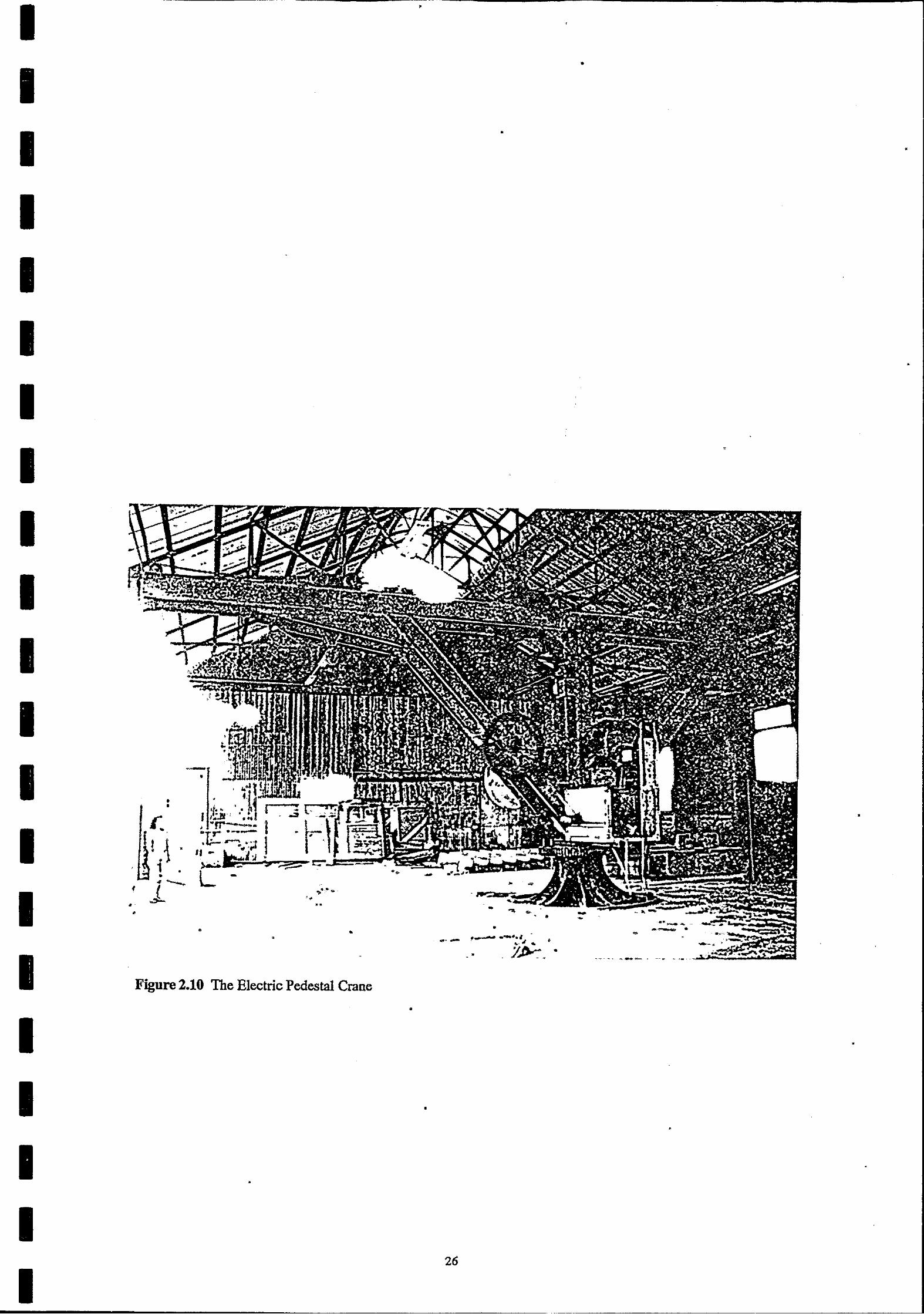
I I I I I I I I I I I I I I I
I I I I I
•
• •
- •
•
."", .. •
•
Figure 2.10 The Electric Pedestal Crane
•
•
•
•
•
•
•
- - . •
f-- --"'.~ -~.- ",." ... '
. . JJ)-, •
•
•
•
26
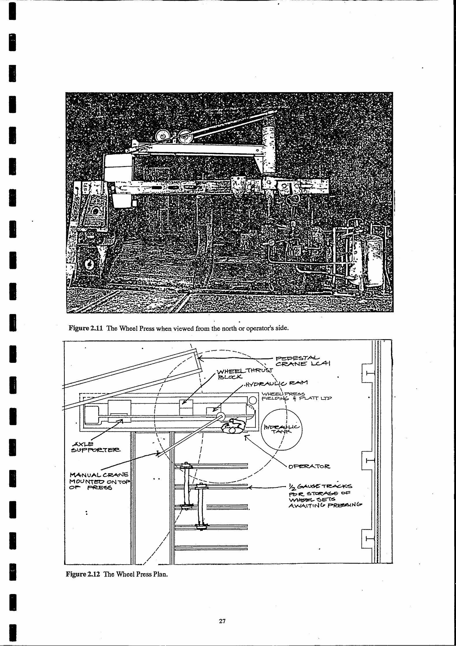
I I I I I I I I
I I I
I I I I I
•
• Figure 2.11 The Wheel Press when viewed from the north or operator's side.
• • \
AXI..B •
!!:>",p~e:t' eJe..
MANU;'L..~ MOt1 me:o ON O~ FR.E15S
• •
Figure 2.12 The Wheel Press Plan.
-- -..---
/ ./
./' ./ ........
• ---~~~~~---- 1I2-c;,...~,.~'S
27
pt;>-=:'s~ ~ . ~~g\,s AlM"<.li,N& p~IN&
•
•
• •

I I
I I I I I
I I I I
I I I I I
, •
GODDEN MACKAY
•
•
•
Pedestal Crane No 41 (or perhaps the manual crane mounted on the top of the press) would be used to lift a wheel-set, and move it into position to press off the whee1.
During pressing, the axle of the wheel-set would be supported on the axle-supporter, using adjustment plates as necessary to suit the axle diameter; the wheel-set would then be positioned with the inner face of the wheel in contact with the right-hand face of the rear thrust-block. The front thrust-block, which had been moved away to allow the wheel-set to be installed, would then be moved back into position so that it also was in contact with the inner face of the wheel. The hydraulic ram would then be advanced (under air-pressure) to bring it into contact with the end of the axle. Hydraulic ressure would then be applied to push the axle through the wheel-hub, the wheel itself being supported during this process by
. . , the manual crane or by the lifting block hung from the lower flange of the crane boom. If necessary, the wheel-set would then be reversed and the other wheel removed in like manner.
The controls on the hydraulic pump on the front face of the reaction post indicate that the ram could be moved under pressure to the left, or retracted to the right. The pressure or force could be monitored by a gauge, and there was a safety valve to prevent overload.
Mter pressing, it seems probable that the axles and wheel-centres would have to be . , inspected and measured to see whether any re-surfacing was required. It would also be necessary to cut the rims from the wheels, presumably by oxy-cutting. There are at present no facilities in the Shop where this work could have taken place; possibly these facilities were removed following the obsolescence of rimmed wheels, or perhaps the components were returned to the Running Shed for inspection and further work.
Replacement rims were prepared in the workshops, and these were re-fitted to the wheelcentres in the Wheel-press ShOp. The process involved heating the rim in a IIfurnaceH to cause it to expand so that it could be dropped over the wheel-centre. Two furnaces were in use, both located in the south-east corner of the shop. The westemmost one was called the IIbeehivell
; it consisted of il'domed oven, 2180 mm in internal diameter and presumably oilfired, with a trolley that could be run into the oven on rail tracks. Wheel-rimes) were placed onto the trolley, run into the oven, removed and fitted to waiting wheel-centres. The rail tracks, the remnants of four vertical steel posts and an imprint on the floor are all that remain of this furnace. The rim-expander to the east of the bee-hive was neither an oven nor a furnace. It consisted of a ring of nozzles, fed with dieseline under pressure, which sprayed fire on the rim. See Figure 2.13. It seems possible that the wheel-centre was held underneath the rim, which could then simply be dropped onto the wheel when the desired amount of expansion had taken place. No evidence of the firing-ring remains, but a rivetted oil-storage tank (approx 1.2 x 1.2 x 1.1 m high, 1.8 m above floor level) stands in the southeast corner of the shed, and an air-pressurised pressure-tank 400 x 500 x 1670 mm long stands against the rear wall of the Shed ..
•
28
•

I I I I I I
o
I I
o
I. •
I
,
· ' • , ;
-------~,~~~--------~----~·~~.,~--~------~·~~--------~~fL~--~---------:~--------~.------~~~----~~--~.--~ ..... . . . . ...... . • ._ I ') . 0;:--" • o· .' ".
III .. "'iIO-~"" -, ... ,
o
I I
,', •
I • I • o , I •
" , o o
i I "
• • , , , o
, ., • I
! f I • • . ' • , • t , ! I • , , I I
i o
'. , t • • , .' , I • • • 'to • • } ! • "
I r 1 I .
• ,.
• .' •
• • IT • •
•
•
•
'.
•
• • •
• o •
• 1
• • •• .. • o •
•
•
" ••
I
• ,
r '.
•
or \
• • •
• • . /
'.
'. "
• • ,
'. •
I • \ •
•
• • • ,
,
• : •
•
•
•
•
•
• •
, • • " • "'''.:- ..
•
,
,
• • ~". "
I' "C • • • • ,
•
0 1
• • •
• • : •
•
o
. ,
, • , ., , •
• I t 8_ • ;.~-
• • • • ., 'lA. I ... .........
I . _ ... w
" " • .-• , . ' ,.~
! • ,
• • " -• '1 ,Y ~---
_. ~ 't- t • • • ... .,·X··t"'r.~ ~.~ ·'tg~·,.;·~ .-
.1 t. ~+_~. ~'I~_~.o:. ~~~~ , ' ~
r -- •
•
•
• • "
•
•
,
• •
-1'''-
• • .' •
• . , •
• •
•
/_11- "...,.l .... 1 .. -;:r---... ....... fo- ... -r ........ - ---1:---"- ...... ::1-', -- ............ .. -.... _- .. • •
I, , LW,":., • - t .... • • • (T. • • • • ~ .".- .... ............ ." ' 41~t \
_ .'f: "11 ~''!;L , .~ 'l'!" , ' '·r .... !..lo' ~ . ~~t.~-c:~-:q'~ ff 'f'~\r.~':.~~._a·t(.i ~(~,'i:_ ~~.) '1.q.!.":'t~'?tQ'HlJ - ~ -K
~ ·PJ~ .. 2'7""~·/~ ~<:r~_~.".'/6;.,;;.S • ...-w.
•
• •
~ · •
•
•
"'a' .... .....
, • •
•
•
•
•
-•
I • • • • , , -• • '~/1
•
• •
• •
•
,
•
• ,
•
•
•
• • .. •
• • • • ' . • •
o
• .'
•
, • - • • ,
• •
Otrr.wwn.w: flM /cV C.l
Sc gle ,,'It" t. 11>: • •
•
,
•
•
•
•
o
o
•
o
,
•
•
•
•
, •
'" ill
•
•
•
o
\ /
•
•
•
•
". '0
•
•
• •
.. . •
•
•
•
•
,.~ ,
•
•
• •
Figure 2.13 The tyring furnace which was ~moved from the Wheel Press Shop in 1986.
• •
, • •
• • • • • • • • • • • • • •
•
•
•
•
•
•
•
• •
o o
•
'. •
•
• •
•
• ,
,
,
•
I
I
•
,
,
·1
,
'/ ~
•
•
. , • • •
•
• It" .. ~
•
•
•
\
•
•
'1.,:" ..... f ~ , •• "
" 'I, III ..... iIl~ ~-....... ...
j i"" "";. • 0 • ~ .. ... • -- .... ~
... '\t ~I "'.. ,;; ,~,,.'" >.J.':... .. .. ..
o' ! .. ~ • ~, • J • .. ~, I ~ .. iI
• io I
I ,
•
,Scv' .. : [Viis!;!! •
• .. ""-•
•
\
•• • • ~~-->-l "r" I I
• ", •
, • .'
• • •
o
, . ,
• •
•
• • o
•
• •
~ ••
• • •
,
•
.iOl .. ,
• • ,
• ,
•
o
•
•
; . ,
,
• .1 ,
•
0'
•
1; -I •
.I I 0 .1 .
" 1 !. " '
"
• • •
,., .' ,.
" "" ~ ~ ,
, ..... , • •
• I
•
o '.
• ,
•
•
•
,
• •
•
" • \
•
! --------j"--j"-------------1~,-,-_il"~~,;.i{,~.:.::.:.:;.I:;::.:.:.::.1r------------... --.. --cc-----------------o----------·~--.~:.----.------------.:>-~'~':·~·--.:.".:·"l~;~· _____ ·i
• •
•
o , · ~ •
•
.,. • , o
i,
•
• , .' .'
. '"I' ...
Gt.dN12 IS affC,t1.
• •
o
• F •
• ,
" • .. .'
1,' .. "' •
a o/'J' WI, •
.' •
•
., •
• •
o. "
•
• '. • • • .- -,
· ' •
•
o , .
• • -''"of'' . "
•
• • •
, • " •
il:. , 0' !
•
· .j'
," ,. ..
• .,
: •
•
, • ,I
• 0 .. , .
• • i· • •
, • • • , • ~, ,
'1 " I'
"
, •
• • I
,,'
•
-0 o
-
.,
• •
• •
• •
•
• •
•
•
•
•
'.'
~
•
,
,
,
•
•
o
•
., •
•
•
•
•
,. .. , .
,
o
• I • !
-•
•
•
•
• • ,
•
•
•
•
•
•
•
•
•
• ,
'. • •
•
•
,
• . " o
~" ..... r •
• •
•
•
•
•
•
•
•
•
, •
o
•
" ... ~' __ "#L''''''' i ""':"f"o'> • .. , • o
". , i -:-. -;".'
'·~r"f.,.. "' . ... .... "'-" -• •
• • • •
•
•
•
•
• • •
•• ,
•
•
•
,
• • •
o
•
• 1
-l •
,
'Rull'~nNc CtJe/{ • • •
• _~8L"sZ!/j~7'.JC;,., .c.11L.., _ · • • ,
•
• " . I .. ,
j I
j
• j I I ,
( 1 •
•
•
•
{' •
• •
,d
, t
•
• •
• • .-
•
,
......
•
•
, ,
•
• , .
• '1" •• ". •
• .,
.. '\ • t, }-
•
~~ ...... ., .... --- . '.' -~ .. , .# ....
,. •
o
I • •
i • • I
' .. •
,-
•
•
• • •
•
•
•
,
........ " . .. .,,,,., ..
H •
... • • -' · -~ . •
,
o
• "
•
•
" • ••• .'
.. ."'. ~~. . '. r .~"
S':. • .. •
i' ':. ." o • •
• ,f'.. ~.-
•
, , - •
.- • • • -': .. · • • •
• .. •• • • • •
,
• o
• • .0 • , e'... " '0 0 "
" .. ~ .... • • · ' ,~1 ..
-•
• o
I .. ?, .'
,
• h ' .. ~ .. - .. ~ ~ " .. .., • • • •
o o ••
• •
.' • • "
• •
•
, -" • ~ .
o
o
No S. W. G. ~.!.!-
11!8- DIA" TYRERINC: NEW TYRE SHOP . ~
•
.. ,
,
•
•
o
'-, ' '0 .. '1' .. ' "
•
, ,
• I
,
,
" •
•
,
• o
,
• • • •
•
•
o
•
•
•
•
29
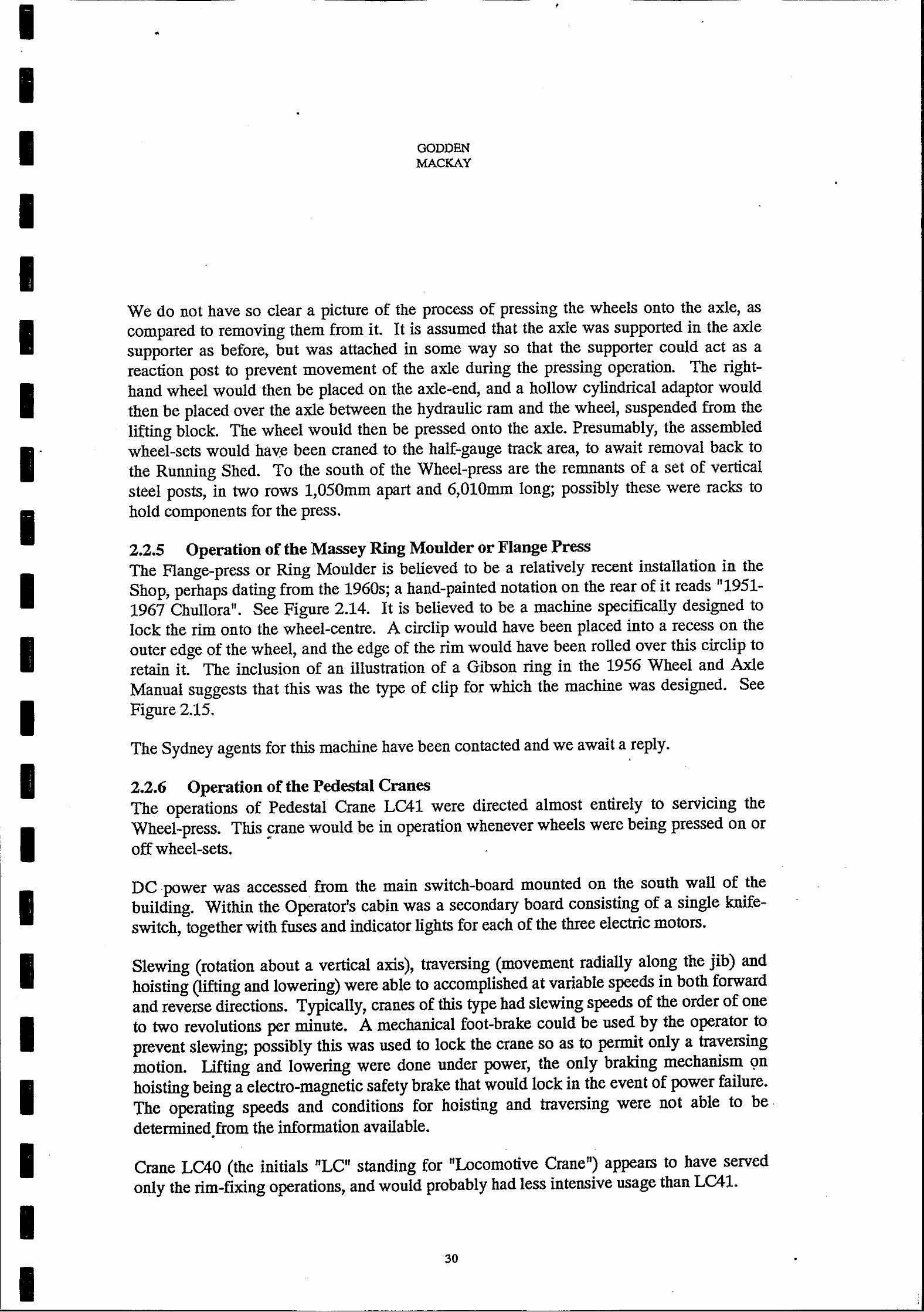
I I I I I I I
I I I I I I I I I I I I I
•
GODDEN MACKAY
,
We do not have so clear a picture of the process of pressing the wheels onto the axle, as compared to removing them from it. It is assumed that the axle was supported in the axle supporter as before, but was attached in some way so that the supporter could act as a reaction post to prevent movement of the axle during the pressing operation. The righthand wheel would then be placed on the axle-end, and a hollow cylindrical adaptor would then be placed over the axle between the hydraulic ram and the wheel, suspended from the lifting block. The wheel would then be pressed onto the axle. Presumably, the assembled wheel-sets would hav:e been craned to the half-gauge track area, to await removal back to the Running Shed. To the south of the Wheel-press are the remnants of a set of vertical steel posts, in two rows 1,050mm apart and 6,010mm long; possibly these were racks to hold components for the press.
2.2.5 Operation of the Massey Ring Moulder or Flange Press The Flange-press or Ring Moulder is believed to be a relatively recent installation in the Shop, perhaps dating from the 1960s; a hand-painted notation on the rear of it reads "1951-1967 Chullora". See Figure 2.14. It is believed to be a machine specifically designed to lock the rim onto the wheel-centre. A circlip would have been placed into a recess on the outer edge of the wheel, and the edge of the rim would have been rolled over this circlip to retain it. The inclusion of an illustration of a Gibson ring in the 1956 Wheel and Axle Manual suggests that this was the type of clip for which the machine was designed. See Figure 2.15.
The Sydney agents for this machine have been contacted and we await a reply. .
2.2.6 Operation of the Pedestal Cranes The operations of Pedestal Crane LC41 were directed almost entirely to servicing the Wheel-press. This crane would be in operation whenever wheels were being pressed on or
• off wheel-sets.
DC power was accessed from the main switch-board mounted on the south wall of the building. Within the Operatorts cabin was a secondary board consisting of a single knifeswitch, together with fuses and indicator lights for each of the three electric motors.
Slewing (rotation about a vertical axis), traversing (movement radially along the jib) and hoisting (lifting and lowering) were able to accomplished at variable speeds in both forward and reverse directions. Typically, cranes of this type had slewing speeds of the order of one to two revolutions per minute. A mechanical foot-brake could be used by the operator to prevent slewing; possibly this was used to lock the crane so as to permit only a traversing motion. Lifting and lowering were done under power, the only braking mechanism <;m hoisting being a electro-magnetic safety brake that would lock in the event of power failure. The operating speeds and conditions for hoisting and traversing were not able to be. determined from the information available .
•
Crane LC40 (the initials tlLC" standing for "Locomotive Crane") appears to have served only the rim-fixing operations, and would probably had less intensive usage than LC41.
30
•
•
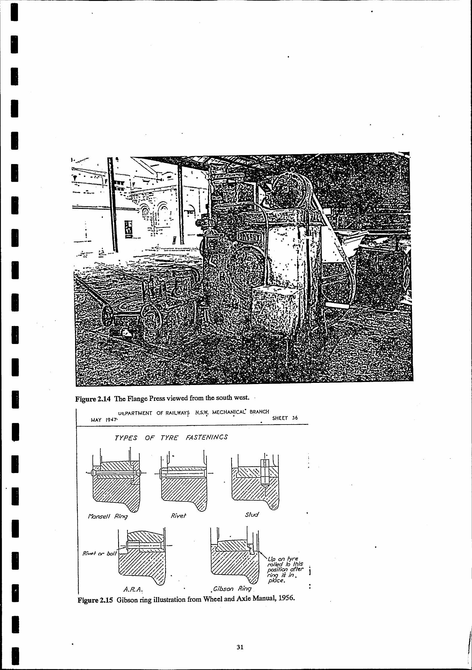
I I I I I I I I I I I I I I I I I I I I I
•
I.~ •
-- ..... "
•
,
, j • ---
• ;,.....-.. ~ -- ..
........ ,;: ---
Figure 2.14 The Flange Press viewed from the south west. .
Ul;.PARTMENT OF RAILWAYS NoS.W. MECHANICAL BRANCH • • •
MAY 19.(7' SHEE:T 36 •
TYPES OF TYRE FASTENINCS
•
, --- ~---- --
rvbnse// Ring River Slud
•
- -I - ._. '""'-'
. • GibsOl1 R/ng.
I' •
•
Lip on tyre rolled /rj 'hIs I
fX?Silk;t! ,affer I rJ'?9 IS In. p/6ce,
• •
Figure 2.15 Gibson ring illustration from Wheel and Axle Manual, 1956.
31
•
•
•
•
I

I I I I I I I I I I I I I I I I I I I I I
•
•
I
•
•
GODDEN MACKAY
2.2.7 Operation of the Pipe-bending Machine
•
,
•
The pipe-bending machine was powered by high pressure water from the main hydraulic system, but, because the machine has been relocated to its present position without any control mechanisms, we cannot deduce details of its operation. See Figure 2.16.
• ,
•
•
•
•
•
•
.~" .. •
•
•
32
•
•
•
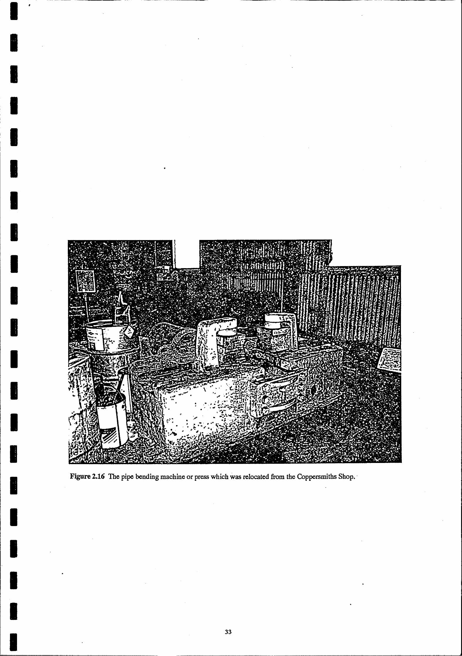
•
I I
I •
I I I I I I I I • '* -, _ .... • • • + .. ~ .. ,. . .. '. .,. - .,
:~ ..
I I
Figure 2.16 The pipe bending machine or press which was relocated from the Coppersmiths Shop •.
I I
• I •
I •
I 33
I I
I I
I
I
I
I I I
I I
• • •
• •
GODDEN MACKAY
3.0 CONSERVATION POLICY FOR THE WHEEL PRESS SHOP
3.1 Description 3.1.1 Introduction and Layout
• •
The Wheel Press Shop is one of a complex of three buildings described in two drawings, dated 9.7.03 and titled: N.S.W.R., Eveleigh Workshops, New Buildings 'B', 'e' and 'D', figures 3.1 and 3.2. The following description uses imperial units taken from this drawing and supplements these with the controlling dimensions converted to metric.
The Wheel Press Shop is shown as Building D and is the western part of a composite building (C & D). This building was to be 250ft Oin" (76.2 m) long, separated into two sections by a steel clad partition wall 100 feet from the east end. The eastern part (building C) is described as the Tin Smith's Shop.
Building D is a steel-clad gable-roofed building consisting of eight bays each 18ft 9in (5.7 m) wide (east-west) and 52ft 4in (16.0 m) deep (north-south), with an eaves height of 19ft Din (5.8 m) and a ridge height of about 33ft Oin (10.1 m). At the time of preparing this report, Building C had been demolished The former partition between Buildings C and D is now an external wall and the cladding is on the inside face of the steel structure.
Clearly, the building was purpose-designed to accommodate the machinery and functions needed to service loco and rolling-stock wheels. The arrangement of the plant and general layout of the shed is shown in Figure 1.2.
In the south-east corner were two furnaces and equipment (no longer in place) where wheelrims were heated and fitted to wheels. Wheels could be brought into the Shop using trolleys on rail tracks which ran from turntables outside the main ShOps, and the wheels could be moved around inside the Shop using the Pedestal Crane No 40 located on the building's centreline in the third bay from the east end. Towards the rear of the building, further to the west, was the Rim press or Massey Ring Moulder, and at the extreme western end was the Wheel-press itself. These two machines were serviced by Pedestal crane 41, located in the third bay from the western end of the Shed. Trolley-tracks linked the Rimpress to No 40 Crane and to the main Sheds. Banks of additional tracks were set in the floor to the north-west of the Wheel-press to hold axles awaiting pressing.
Two small jib-cranes are mounted on columns in the rear wall. On the column 17.2m from the east end is a crane with an I-beam jib about 6.5 m long supported by two steel flats. The crane on the south west corner column has a jib (of about the same length) composed of a dumb-bell rail line section forged at its outer end for attachment to its supporting rod; it carries a plate "Load not to exceed 3 cwts." .
34
•
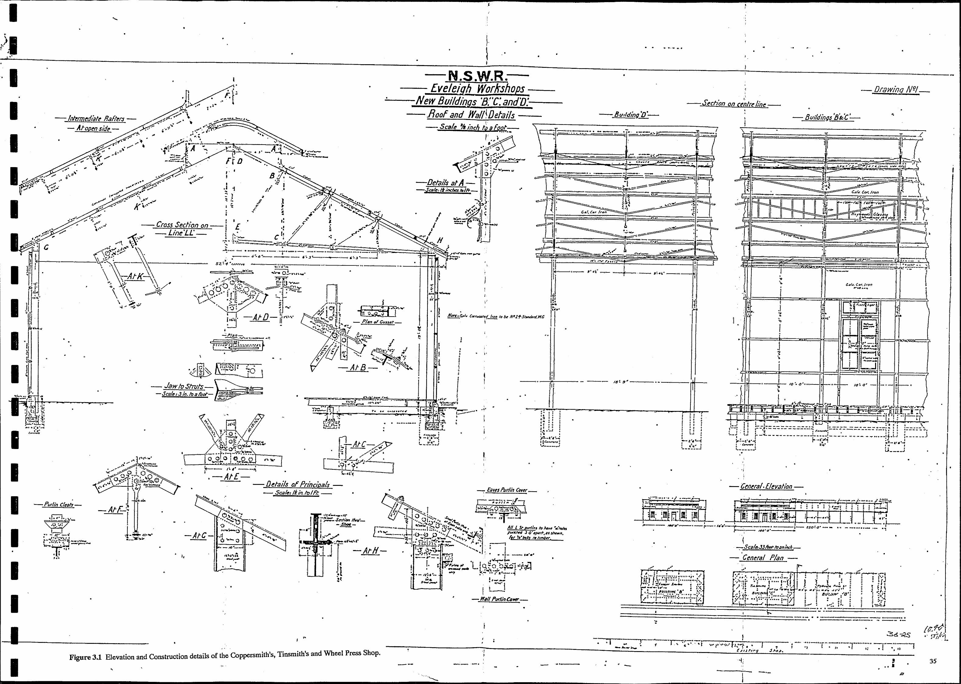
I
-•
•
•
I
I •
I
I I I I •
I I
•
. •
•
•
c
•
• • •
• •
•
. -Purlln C/I!al:r-
•
•
,,('"... •. , ,.. -
•
•
•
•
•
•
•
•
\
•
•
•
" 1 •
•
I •
I' • I
• .1 1 ~
:: } ~ -, I -:: • I
I
£
I ,
tJ· •
•
•
t.-.- " " _->. I . . . -,
,-Atl
•
•
•
•
•
•
- Details of Principals
"
• ~ ""I;"'"" ><. '. . . . ~"
- Sca/~:!t/n.ltJ/f'I:_
~ '" .. \ ... ~' I ..... . -AtC-
.J. •
• I,
• " .
, .
•
I ... •
•
•
•
Figure 3.1 Elevation and Construction details of the Coppersmith's, Tinsmith's and Wheel Press Shop.
•
• • •
•
!-
~ • • • •
•
N.S.W.R.£ve/eign. Workshops-
New Bul'ldin[ls '8;"C:andV:---- .Roof and WallWefails --
-Seall! *':?ch fqafM!::::- \ ~
- -,
l-.-'
! • ,
" ~ .",p b
b
I -
~~
. . ~~~ ..........
,
! ,
•
I
,
I
· Narc'r~/., CtJl'ruoJ~d_ Iron ID 6~ ,N'21-.s. hnd.M,w.a
I • • • " , I , I • " ,
f
• •
-- -.
I
\ 1
,
I
,
, ,
,
, •
-
,
• • •
•
..
-
:. '" "
•
•
, ,
, ,
"
!~: .. , I
, • ..
I
, I
I ,
,
'. ,~ • '. ,: '.' , •
•
••.•• _--
!
• • .... ....... ", • -. .- •
•
' ...... _ .... - .. ; .. ,1
,
r ," ~.
. ~- - ..-•
G.I. ~.,.
• • -_ ..... ,
j
~.;,.-',~ ,~ -I-i'" ".....,.......
- - 18! s'-
,
•
• •
•
, -
' -,
•
~
.~ ':'.i.~ -
..,~
•
•
• •
• • • •
1 -. -
, \
-- Drawif7!l. Nr?/_
Section on c~'ntre linl! •
I
! - BC/Jidings BkC~
-J 7
'\ --;-
, .. < ,
, 'Ii /
..~ ... , . . . '\
i .... ~'; r.: ."
Ii
-~ .~~ III ;;;; t" . CJI", t«-Iron
. -">
,
~. ~, .. .t ~ , j \1
~Il , m- . .,
¥'y ~i "
:;= , -. . I- . I
b. • ,
I· "'" , , I " ,
, , ~
.
f ~
, , -----.. ,
! ~ b
~ ~~~ ,
~ , . , I !' .- ,
• . : , , .. ,
! , , • ... cJI .... Cor • ./rDn
,
-~ ..... ",
i -i , ,
,
" , 1-. ~
!-•. , ,
I ~
,I,
• ,~
'" • .. ,-I, , , ---, , ,
• • -- , , , , rf;;:; f,:;;-.: I ~
, "
,
,
:
I
, h;-' , , , ,
• , ~ ,
, , - I :
10".0 , ,
, IO~ o~ • , !
.' , , , • j .J.
,
•• , I' ,!: ~ :' I .I,·f 'I • J ~ ~, '. I J .,
, ·/l<S , ~lfJ . :ii ::(
, 0 1 ,: ' ' 1 .. / ',1..
0,
o ",~ _. I I~, ,r 1, 'I' 11 I ;, 'I...; I.
,:=-= ! I :.. J :'. .' ~;j ;::--: .. -------- -... ~ • , .~---- .... -- - - - -. - - ';' ;;;:;-:;-i ,
• 'f 11 • ------_ ...... - , .- ......... -.' 'I-_ ... ",~ , ' .
,t '.' ,~ .' -Z.'6'--'; , . : a:,." j" --- ... ~-
· ~-,.II t .. ....:~- ...... -- ... _- -... ---~ ... , •
[ -:n . ;~~.
• . •
• 'I
- C~n~ral.[leyalion-•
{ -:-St:a/I!>JJ Ii!d m3",nm_
• - Ceneral Plan
-,: , ---~-,- ~. -"-
, . , .... _-- ......... _-- ..... " : ... --- ....... : ~._&, •. J
f . = •
• •
•
• •
•
•
, ., . •
•
•
35
,
I
•
•
•
•

"
• , , .-... --------:--------~r_----------:-----------If I s~ . .
I I •
• I I , j
•
" .. . . . . .. _ ' . '. :' . J. -..... r~----------~·--· ---.--------------~.~.~~~._~.~"------. ___ · __ ~·Ll __ ~ I : l N.S.W.R .. -- l-·---------,-·-c-·-·~I
, -S~cfiononunlr~/i,,~- _Eveltligh Workshops -Ent! ElevaHon- ' . -Draw/,7Q.,N.2.- •
•
•
I I I
•
I
I I
• 1'1
I
-Myjlg}]t Detar:'s-- Ski"i 3tncks Lc~Foot_
•
•
•
-•
n
-"B -c,,.,-re...-ll. ... --
•
,
•
Gahh DetaIls B . £~ .' - Half Cdron fl~moytd --New BUIldings '8;'(;: andYX- I ./1 ~ e ! racmg, - . Scarfs toPur/!ns_ • 1rl~~~:::: -£a~g hm(fI9--
_S~/e!" inch foq,("OtfC- - Scalr' IUncbe5loafoot_ I -SecHcn at End of S!ryJ!ght·_-
•
. -
, •
-End Principal. Buildi.7q·O"-8~3t~r Ct'tr OMi? SJr1~ ,
t , t" , <0: _ ......... ·.3 4 _,_,~ ...... ""
-AtF"+::'~' . r 0' ,~'"'"" .. <'::::1" I :@"...! .0_ .. --.' " ,
'I t ••
• -
--.... ..--~---"
.. ., , -I.
,.'t\oioA.r.... 'I l I
.... 'W:;g;';;L t, ' I'·" o ". t
I , 11 ~.
•
•
~~~~~ ! ~I! r>c ~"~~.5 [',", --,,~7" ~"!t .. ~75~i;:!h4~'_"t.-.r-- -- It It ,___ _ _ t~ -. ....... - ",~,-
-•
I . I . i
• • I
i :::: ~~ . 11 ,. } · r " ·w-l '*'f'J=; •• ===~~=j ::),:;:11=-
~ ~J'-AtH-\]r ~ -r :~
• - Planof Ra/kr Brac/nq-
• at end ll1ys "
•
, . ,
, , ,
I
•
•
•
.. , •. Q. ~';.~J".t , i ot...· '_ r>. to:' ,. _ ~_~ _ --.r_.. ~-... ~- ~- I' .. ~ .. " .. _, _~_t.'':;:-.::"'-='"'~'''
•
• •
• •
... '~. h ,I _
.... J ... s ...... ·:J,
•
tj, ......... _ 'Oj~. r' .. ~ .. :·l· ,,-,. ...... : • ',tl ~
............ --"', ... """ -- ... "". "-...
•
- - ........... _ .~,. f;l. ..
, 'I ,1
1'1 I.: ,
•
, ....... 1.-'.,.1 ... - -.-... -:- ~.'- -[;mreftJ [;n't:. ---.-- -
.- ,-'" p----1:.::===========' ""-'''''': .' , .. ~, .' I ,. .,
• •
J..: ~ '.
i • • •
•
•
,
--.--~ ,-------------------------------1---- --. -------------'----: -- ---.-~ ... ---_ ......... " -
•
I I
•
I I ,I; , I
I I I
•
I
I
I
I , I • I
i I I •
I I
I
. --.......... .. - -.. ---- -' --'-.:::.~--Figure 3.2 Elevation and Construction details of the Coppersmith's, Tinsmith's and Wheel Press Shop, - • • -. • ., • 36
• .-. • • " • . - • •

I I I I I I I I I I I I I I I
I
•
Figure 3.3 The Wheel Press Shop. viewed from the scut east
Figure 3.4 The Wheel Press Shop, south west corner. •
37
•
•
••
!
•
•
•
I I I I I I I I
I I I I
-------------------------------------------------.. ,
3.1.2 Wall framing.
GODDEN MACKAY
Columns in the north wall are 12 x 6 x 54lb I-beams, at 18ft 9in centres with webs aligned north-south. In the south wall they are 12 x 5 x 32 lb at 9ft 4.5in (2.85 m) centres. These columns are embedded in mass concrete footings 2ft 6in square and 5ft Gin deep. The columns are in the east and west walls are 12 x 5 x 32lb I-beams at various spacings with webs east-west. An unusual feature is that the corner columns are treated as part of the end walls with webs aligned east-west; in modern practice they would be proportioned as facade columns.
The west and south walls are braced using opposing steel 4 x 5/8 inch steel straps, two in each wall plane.
3.1.3 Roof Framing. Roof trusses span north-south at 18ft 9in (5.7 m) centres (except at the west end, where the first three trusses are spaced at half distance), supported on the columns in the north facade. They are of riveted and bolted construction. The top chord is a 4 x 4 x3/8 inch Tee section, the lower chord a 4 x 3/4 inch steel strap. The vertical web members are 2-1/2 x 3/8 inch straps and the diagonal web struts are 3-1/2 x 3-1/2 x1/2 inch (or 3 x 3 x 5/~6 inch) angles.
< The end connections of these web struts are unusual in that they are formed by slotting the angle along its back and crimping the two legs until they are parallel, forming a fork which passes around the webs of the chords. The trusses were fabricated in two halves, using single rivets at the web members, and these were bolted together using gussets at the kingpost.
Half-way between each pair of principal trusses is an IIIntermediate Rafterll, formed from a
4 x 4 x 3/8 inch Tee; this is strutted (on 1-1/4 inch rounds) from 2-1/2 x 3/8 inch truss bars which are suspended from the principals. The southern Intermediate Rafter is supported by a wall column and four truss bars (including one at the ridge), whereas the northern one has one additional truss bar near the eaves, where there is no supporting column or beam. (This form of construction was adopted to permit the wide spacing of the northern columns, and is very uncommon. Modern practice would use a steel eaves beam spanning between the northern columns to support trusses at constant spacings. The westernmost pair of columns does use such a beam in order to support roof bracing.)
The building has a ventilated ridge, which is framed in 4 x 4 x 3/8 inch riveted Tees which are bolted to the principal and intermediate rafters. The end bay of the roof is ~ross-braced using 3 x 3/8 inch steel straps. In common with most roofs of this vintage, this structure was not designed to resist wind uplift., Tension members in the trusses and the truss-bar system for the intermediate rafters have no capability for stress reversal.
3.1.4 Cladding The walls and roof of the building were clad in 24 gauge galvanised corrugated iron. The north wall is open.
38

I I I I I I I I I I I I I I I I I
•
GODDEN MACKAY
•
Girts on the south wall are 4 x 3 inch timbers, arranged to provide four approximately equal spacings. On the east and west walls the girts are also 4 x 3 inches for the most part.
The roof purlins are 5 x 3 inch. AB shown on the drawing, tnese were to be spaced at approximately 7 ft, supported on angle cleats, but intermediate purlins have now been inserted by bolting. The fascia board is 14 x 1-3/4 inch with a 6 x 4 inch galvanised gutter; the barge board is 15 x 1-1/2 inch.
Six windows are located in the south wall. They are 7 x 5 feet overall, consisting of two casement sashes with an upper section of fixed glass in three panes. There are no doors.
3.1.S External Features of the Services Bridge An unusual bridge carries air and water pipe-lines over the road from the Main Workshops to the western end of the Wheel-press Shop. It is composed of wire rope in the form of a funicular, directly supporting the pipes, and is strongly reminiscent of the method used to support overhead cables on electrified suburban track. It is anchored to the western end of the Shop by two structural members bolted to the central pair of columns.
3.2 Documentary Evidence Unlike much of the equipment, buildings and structures at Eveleigh, very little documentary . evidence exists on the Wheel Press Shop. The original plans which are noted NSW Railways, Eveleigh Workshops, New Buildings B, C, D, Sheets 1 & 2 (SRA601-28) exist and provide excellent reference to their construction. The buildings B, C and D were to be erected parallel to the main workshops building and were to be some five metres to the south of the two standard gauge rail tracks which ran on the south side of the main workshops building itself. It would appear that Building A which was basically of a similar construction was to become an adjunct to the blacksmiths shop, later to be known as the Oliver Shop. (However, this cannot be confirmed by reference to the documentation). The plans of the building are dated 9th July, 1903 and the subject building is noted as Hydraulic Press (the next word is missing) Building D, but there is no indication of what type of machinery was to be erected in the building.
The Railway Budget of the 1st August, 1903 stated that the decision to erect the buildings had been made and that Building D was to be the new Spring ShOp. Springs had·formerly been made in the main workshops near the blacksmiths section, however with the expansion that was taking place at the turn of the century, a separate workshop was needed for the manufacture and heat treating of springs for both locomotives and rolling stock. It would appear that the Spring Shop was not relocated to Building D (the Wheel Press Shop) as this shop was designed with one side open which is unsuitable for spring making. Rather, a building especially erected between the main workshops and the new engines house was to be designated the Spring Shop or New Spring Shop and this was constructed in 1903 [NSW Shop Order 1st December, 1902J and remained unti11982 when it was demolished (Jack Bruce, personal communication January, 1994).
39
•
I I I I I I I I I I I I I I I I I I I I I
GODDEN MACKAY
•
All drawings of Eveleigh show the subject building as the Wheel Press Shop or Hydraulic Wheel Press ShOp. The account of the visit of the Institution of Engineers Australia, Sydney Division, to the Eveleigh Workshops on the 11th October, 1922 described the Hydraulic Wheel Press Shop and Tyre Shop as being
... devoted to the assembling of axles, wheel centres and tyres.· Hydraulic presses are installed for removing centres from axles and replacing them, while a tyre heating plant is provided for tyres for removal from or subsequent shrinking, on to centres.
The building was never equipped with overhead travelling cranes and' to function as a Wheel Press Shop required two large cranes, one for the tyring furnace and one for the wheel press. The Henry Berry cranes LC40 and LC41, installed in the Wheel Press Shop in 1917 and 1918, replaced the previous Hydraulic Cranes which had become badly fractured and therefore dangerous to use. The two Henry Berry cranes at present located in the Wheel Press Shopare on the 600 volt DC current which was standard for the NSW Government Railways at the time.
. A photograph of the Wheel Press Shop (undated but probably taken between the Wars) shows a hydraulically powered cable and chain testing machine on the south wall of the workshop. See figure 3.5. This hydraulic tester was about 20 metresin length and the head stock was at the west end of the building. It is not known when the machine was removed or its fate. No discernible evidence of the machinery remains.
3.3 Discussion of Significance The Wheel Press Shop housed machinery which performed functions which were integral to the operation of the locomotive workshops. The Wheel Press Shop was located on the site from 1903 until the early 1980s when, with the replacement of the tyred wheel with the solid wheel, some of the functions were removed to the main workshop.
The workshop is a purpose designed and built industrial structure which performed a specific range of operations for some 80 years and was the principal wheel and tyre shop in the workshop. Like almost all buildings on site, it and the operations it supported, was vital to the operation of the NSW Railways.
The building's design and construction is unusual and it incorporates some rare detail now evident in few railway buildings throughout the State. The webb struts are composed of slotted and crimped angle section steel while the roof is composed of principle trusses and intermediate steel rafters which permit the wide spacing of the north posts (see Section 3.1.2).
•
The style of building, with its rusted corrugated iron walls, gable roof with surmounting monitor, steel framing and completely open north wall is rare. Its form, with its intact maChinery and evidence of former functions such as the inground rail tracks, concrete slabs, make it an easily interpreted annexe to the main workshops.
40
•
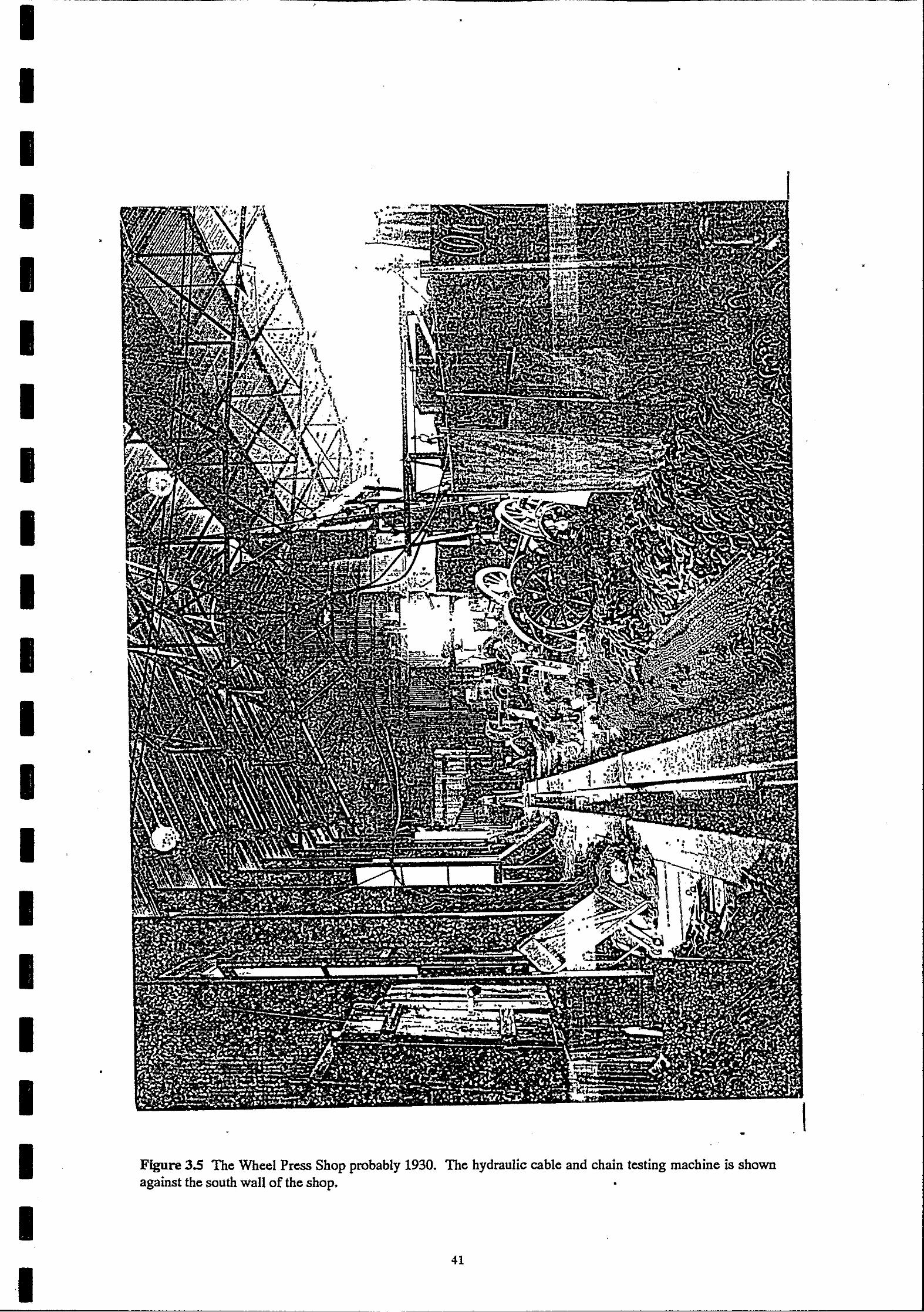
I I I I
•
I I I I I I I I
•
I I I I I
•
I I I I
Figure 3.5 The Wheel Press Shop probably 1930. against the south wall of the shop.
•
-The hydraulic cable and chain testing machine is shown
•
41
•
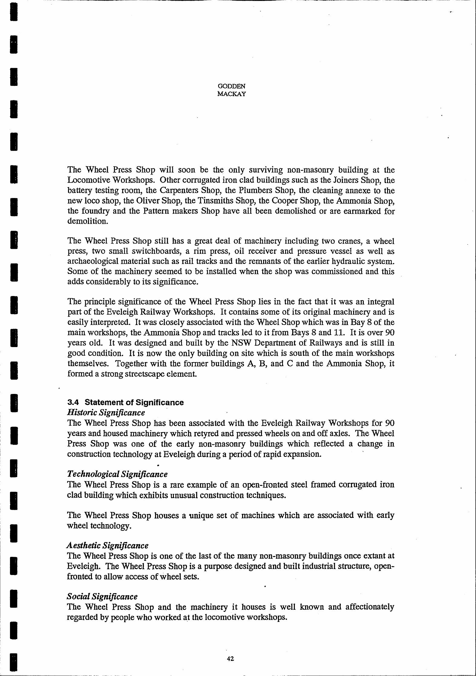
I I I I I I I I I I I I I I I I I I I I
GODDEN MACKAY
The Wheel Press Shop will soon be the only surviving non-masonry building at the Locomotive Workshops. Other corrugated iron clad buildings such as the Joiners Shop, the battery testing room, the Carpenters Shop, the Plumbers Shop, the cleaning annexe to the new loco shop, the Oliver Shop, the Tinsmiths Shop, the Cooper Shop, the Ammonia Shop, the foundry and the Pattern makers Shop have all been demolished or are earmarked for demolition.
The Wheel Press Shop still has a great deal of machinery including two cranes, a wheel press, two small switchboards, a rim press, oil receiver and pressure vessel as well as archaeological material such as rail tracks and the remnants of the earlier hydraulic system. Some of the machinery seemed to be installed when the shop was commissioned and this adds considerably to its significance.
The principle significance of the Wheel Press Shop lies in the fact that it was an integral part of the Eveleigh Railway Workshops. It contains some of its original machinery and is easily interpreted. It was closely associated with the Wheel Shop which was in Bay 8 of the main workshops, the Ammonia Shop and tracks led to it from Bays 8 and 11. It is over 90 years old. It was designed and built by the NSW Department of Railways and is still in good condition. It is now the only building on site which is south of the main workshops themselves. Together with the former buildings A, B, and C and the Ammonia Shop, it formed a strong streetscape element.
3.4 Statement of Significance Historic Significance The Wheel Press Shop has been associated with the Eveleigh Railway Workshops for 90 years and housed machinery which retyred and pressed wheels on and off axles. The Wheel Press Shop was one of the early non-masonry buildings which reflected a change in construction technology at Eveleigh during a period of rapid expansion.
•
TechnolOgicalSignijicance The Wheel Press Shop is a rare example of an open-fronted steel framed corrugated iron clad building which exhibits unusual construction techniques.
The Wheel Press Shop houses a unique set of machines which are associated with early wheel technology.
Aesthetic Significance The Wheel Press Shop is one of the last of the many non-masonry buildings once extant at Eveleigh. The Wheel Press Shop is a purpose designed and built industrial structure, openfronted to allow access of wheel sets.
•
Social Significance The Wheel Press Shop and the machinery it houses is well known and affectionately regarded by people who worked at the locomotive workshops.
42
•

I I I I I I I I I I I I I I I I I I I I I
-----------------------------------------------,
• GODDEN MACKAY
•
3.5 Constraints Constraints arising from the Statement of Cultural Significance. The Wheel Press Shop and the material it houses is of some cultural significance and the building should be retained and conserved. '
The existing building fabric and the configuration of the building should be preserved and maintained. .
~ Statutory Constraints The Wheel Press Shop is not subject to any conservation instrument issued pursuant to the NSW Heritage Act 1977.
The Wheel Press Shop falls within the SRAs Eveleigh Heritage Precinct. This precinct is included in that Authorities Section 170 Register. It is not specifically mentioned on that Register. The Register is required to list items which could be made subject to a conservation instrument. It is the expectation of the Heritage Council that statutory authorities will take responsibility for appropriate conservation and management of items on their Section 170 register.
Under the provisions of REP26, Amendment 1, Eveleigh Precinct, The Wheel Press Shop falls within the area which is subject to Master Planning Requirements and the Minister is the consent authority.
The Urban Development Plan for the Eveleigh Precinct requires that Conservation Plans be prepared for heritage items to determine appropriate and economically viable adaptation. Conservation Plans are to address the guidelines for conservation management established in a Conservation Policy for the precinct.
The Wheel Press Shop is not included as a heritage item in the Regional Environment Plan which identifies the following buildings in the Locomotives Workshops site; the Locomotives Workshop Bays 1-15, including the machinery in Bays 1-4, the new Loco Shop, the Works Managers office and the Large. Erecting Shop.
• •
The Wheel Press Shop is not included on the list of additional items identified in the draft Conservation Policy Eveleigh. However, the traverser, the cast iron water tank and stand, the two oil tanks and the machinery in the Wheel Press Shop itself are identified. It is further recommended in this document that the machinery stored in the Wheel Press Shop should be relocated in Bay 4A.
The Draft Conservation Plan Eveleigh states in the Section of Strategic Conservation Issues under sub-section General Conservation of Building Fabric that:
extent building fabric, both internally and externally, from all periods should be selectively conserved to illustrate the development and growth of the complex in preference to an emphasis on one particular period of use.
43
•

I I I I I I
I I I I I I I
I I
,
•
GODDEN MACKAY
•
Client Requirements The client, the Commercial Development Branch of the Public Works Department of New South Wales, desires that the building be demolished and the machinery in it be removed 'and conserved to facilitate access to varIous parts of the site.
3.6 Conservation Policy The following points must be recognised during any discussion of the policy.
(1) The building is recognised as an item of the environmental heritage.
(2) 1'1!e cultural significance of the building is closely associated with the machinery which is contained within it. If the machinery were to be removed, the building would decrease in significance.
(3) If the machinery were removed it would be extremely difficult to adapt the building to any other use without an unacceptable decrease in its significance.
(4) If the machinery were in fact conserved in situ, a further set of conservation procedures would have to be carried out if the machinery were to be moved at some later date.
(5) If the building and machinery were to be retained in situ, the building would require immediate and then on-going maintenance. The relics within the building would have to be conserved, maintained and secured. This would in all probability be expensive and difficult.
(6) Conserving the machinery in situ isolates it from the equipment in Bays 1-4A and will require the maintenance of two separate collections of heritage relics.
(7) The Conservation Poljcy Eveleigh identifies the need to conserve building fabric from all periods in order'to illustrate the growth and development of the complex. The Wheel Press Shop was constructed in 1903 and the first phase of the Loco Shop or New Engine Shop was constructed between 1907 to 1908, while the eastern end of the New Erecting Shop was built between 1889 to 1900 and further extension was commenced in 1900 and continued to 1906.
The Wheel Press Shop is the one remaining non-masonry building remaining from this period, however, it is not the only building constructed on the workshop site early this century.
There are a wide range of options which would be considered for the future management ~f the buildings. However, these can generally be narrowed into three main options.
(1) Conservation of the building and the in situ conservation of the relics for the long term.
• 44
__________________________________________________ -.J
I I I I I I I I I I I I I I I
I I
•
GODDEN MACKAY
•
(2) Conservation of the building and in situ conservation of the equipment for the short . term with a view to possible relocation at a later date.
(3) The demolition of the building and relocation and conservation of the equipment with a view to the later reinstatement of the equipment in Bay 4A.
The first option is acceptable on heritage grounds but unacceptable to the client as the site may be required for future development of the Australian Technology Park. The second option is acceptable on heritage grounds but again unacceptable to the client as this will require conservation procedures to be carried out twice on the equipment and may also involved expensive refurbishment of the building itself.
The third option is acceptable to the client but can be challenged on heritage grounds in that the building may not be required by the ATP in either the short term or the long term.
Recommendation Because of the needs of the client and the necessity for securing and conserving the equipment in both the short and the long terms, it is recommended that the equipment be relocated, conserved in the short term and recommissioned in the long term .
It is further recommended that the building may be demolished if a new purpose be required for the site.
3.7 Implementation For the implementation of the policy pertaining to the various items of machinery and material within the Wheel Press Shop, please see the following sections.
•
•
•
•
• 45
I I

\
I I I I I I I
I I I
I I I
I
,
,
GODDEN MACKAY
•
•
4.0 CONSERVATION PLAN FOR THE PEDESTAL CRANES. The Wheel-press Shop contains two Pedestal Cranes, identical in size and detail. This Plan deals in detail with Crane Number LC41 which serviced the wheel-press itself, but, except where stated otherwise, all items in the plan shall be taken to apply equally to Number LC40, which served the eastern end of the Shop. (See Figure 4.1).
4.1 Description: Pedestal Crane No 41. 4.1.1 Identification. The crane carries the following identification marks:
Inside the control cabin: SWL7Ton CLASS 3 LC41
Chalk-marked on the outer walls of the cabin: No1
Cast into the counterweight: HENRY BERRY & CO LTD, LEEDS
On the boom: LOAD NOT TO EXCEED 7 TONS
It is located adjacent to the wheel-press, distant 12.8 m from the western wall and 7.8 m .
from the northern wall. .
It has an overall height (to the top of the boom) of 5.3 m, overall length of 11.4 m and overall width at the base of 2.6 m (excluding the cabin). Its mass is estimated at 17,000 kg total, which includes an estimated 5,600 kg of scrap iron in the counterweight.
4.1.2 Description. The crane (Figure 4.1) consists of a pedestal (A) which supports a large ring gear (B) and a vertical king-post. Suspended from the king-post is the rotatable crane assembly, which consists of: a horizontal jib (q; a vertical mast surrounding the king-post (D); diagonal braces (E & F); a counterweight (G); and the operators' control cabin (H). Mounted on the crane assembly are three electric motors, drive chains and rope tackles to enable loads to be
hoisted, traversed or slewed . •
It is anticipated that the crane is mounted on a massive concrete foundation, possibly 30 cubic metres in extent. Calculations show that the centre of gravity of the crane falls within the baseplate for all rated conditions ofloading, but it is probable that the greater part of the factor of safety against overturning was to be provided by anchorage to a foundation block.
46
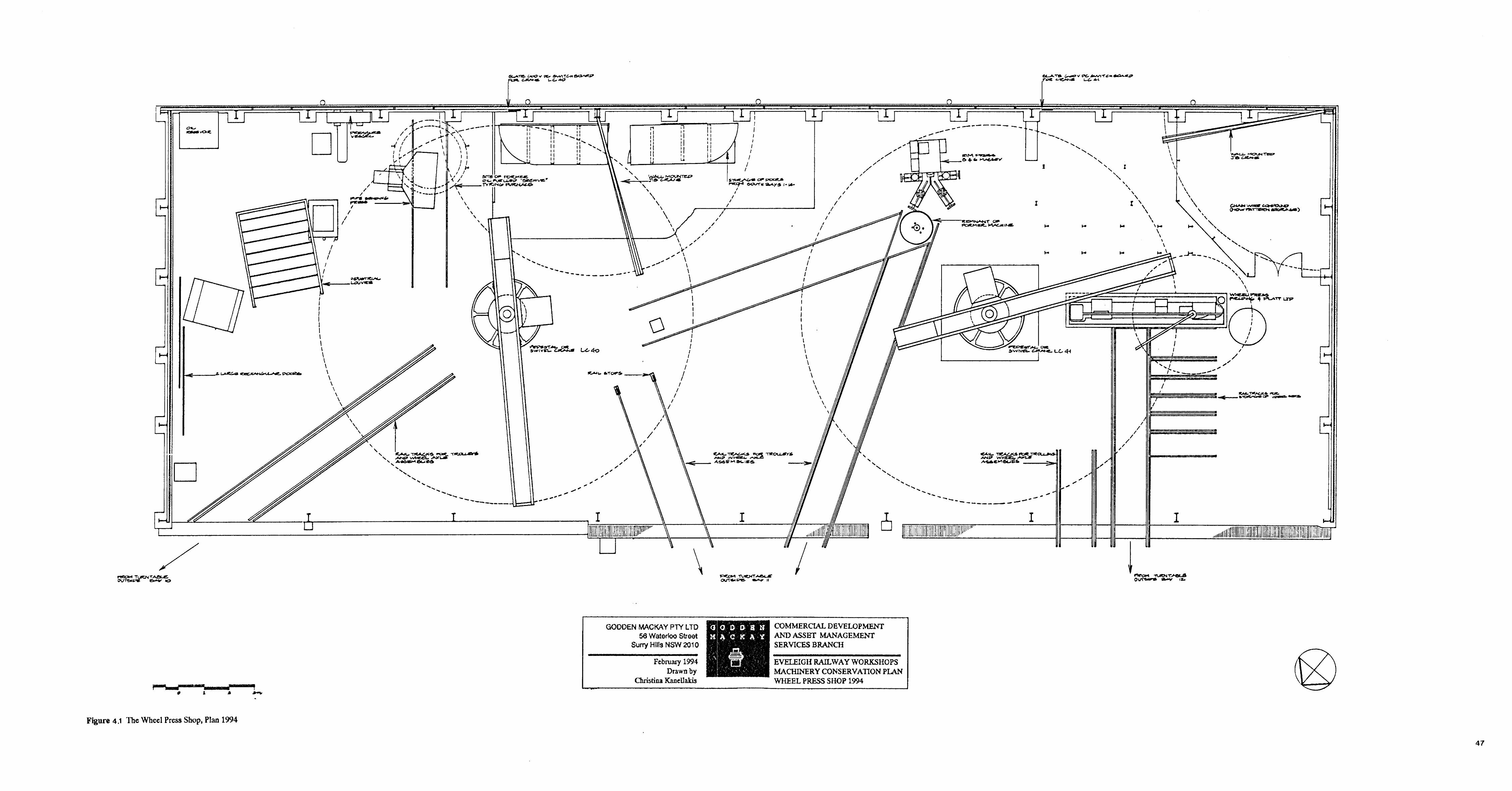
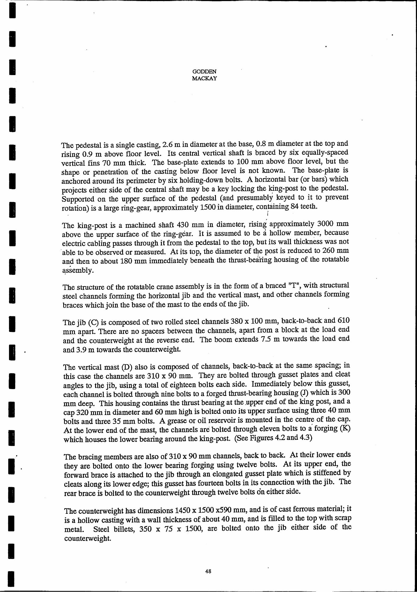
I I I I I I I I I I I I
1 I I
•
I· I 1 I
•
GODDEN MACKAY
•
The pedestal is a single casting, 2.6 m in diameter at the base, 0.8 m diameter at the top and rising 0.9 m above floor level. Its central vertical shaft is braced by six equally-spaced vertical fins 70 mm thick. The base-plate extends to 100 mm above floor level, but the shape or penetration of the casting below floor level is not known. The base-plate is anchored around its perimeter by six hOlding-down bolts. A horizontal bar (or bars) which projects either side of the central shaft may be a key locking the king-post to the pedestal. , Supported on the upper surface of the pedestal (and presumably keyed to it to prevent rotation) is a large ring-gear, approximately 1500 in diameter, containing 84 teeth.
I . I
,
The king-post is a machined shaft 430 mm in diameter, rising approximately 3000 mm above the upper surface of the ring-gear. It is assumed to be a hollow member, because electric cabling passes through it from the pedestal to the top, but its wall thickness was not . able to be observed or measured. At its top, the diameter of t~e post is reduced to 260 mm and then to about 180 mm immediately beneath the thrust-beanng housing of the rotatable
• B:ssembly.
The structure of the rotatable crane assembly is in the form of a braced "T", with structural steel channels forming the horizontal jib and the vertical mast, and other channels forming braces which join the base of the mast to the ends of the jib.
The jib (C) is composed of two rolled steel channels 380 x 100 mm, back-ta-back and 610 mm apart. There are no spacers between the channels, apart from a block at the load end and the counterweight at the reverse end. The boom extends 7.5 m towards the load end and 3.9 m towards the counterweight.
The vertical mast (D) also is composed of channels, back-ta-back at the same spacing; in this case the channels are 310 x 90 mm. They are bolted through gusset plates and cleat angles to the jib, using a total of eighteen bolts each side. Immediately below this gusset, each channel is bolted through nine bolts to a forged thrust-bearing housing (J) which is 300 mm deep. This housing contains the thrust bearing at the .upper end of the king post, and a cap 320 mm in diameter and 60 mm high is bolted onto its upper surface using three 40 mm bolts and three 35 mm bolts. A grease or oil reservoir is mounted in the centre of the cap. At the lower end of the mast, the channels are bolted through eleven bolts to a forging (K) which houses the lower bearing around the king-post. (See Figures 4.2 and 4.3)
The bracing members are also of 310 x 90 mm channels, back to back. At their lower ends they are bolted onto the lower bearing forging using twelve bolts. At its upper end, the forward brace is attached to the jib through an elongated gusset plate which is stiffened by cleats along its lower edge; this gusset has fourteen bolts in its connection with the jib. The rear brace is bolted to the counterweight through twelve bolts on either side.
The counterweight has dimensions 1450 x 1500 x590 mm, and is of cast ferrous material; it is a hollow casting with a wall thickness of about 40 mm, and is filled to the top with scrap metal. Steel billets, 350 x 75 x 1500, are bolted onto the jib either side of the counterweight.
48
•
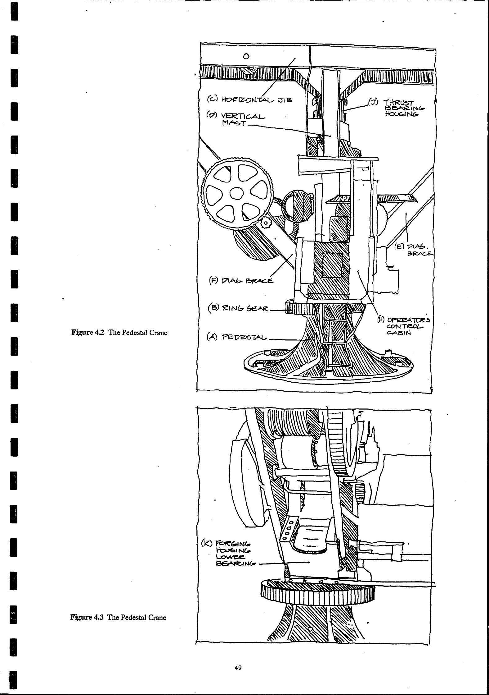
I I I I I I I I I I I I I I I I I I I I
•
•
•
•
Figure 4.2 The Pedestal Crane
Figure 4.3 The Pedestal Crane
•
o •
(~) Ho1~IZ:ON,,;A:L.. ;;)113
(17) Vet< 11c.AL-MAo::.T-___ L
t?IAb .
49

I I I I
I I
I I I I I I
I I I I I I
•
•
GODDEN MACKAY
The control cab (H) is mounted on a pair of angles which are bolted to the bottom edge of
the forging for the lower kingpost bearing. Its axis is perpendicular to that of the crane; the
operator sits facing the crane hook with his back to the counterweight. It is of timber and
steel construction with its floor about 1100 mm above the floor of the shed; a four-runged
ladder gives access, The cabin contains three electric motor speed controllers with five
forward and five reverse settings. They are 600 v DC operating through a series of air
cooled iron resistors located at the rear of the cabin. A single mechanical foot-brake,
located between controllers 1 and 2, operates on the slewing motor drive chain. On the
rear wall, behind the operator's head, is a knife switch and three fuses and indicator lights.
A 600 v DC Radiator is on the rightof the cabin.
The crane hook is attached to a sheave block which is suspended from a double-sheave
carriage by the hoisting cable. This cable is anchored to the front end of the jib, and passes
around the forward carriage sheave, down and beneath the hook sheave, and up and over the
rear carriage sheave. Thus, the carriage is able to be traversed along the jib without altering
the height of the hook. The hoisting rope passes over a sheave mounted between the
channels of the jib and then vertically downward to a hoisting drum mounted on the
forward brace. The drum is driven by a motor mounted in front of the vertical mast; an
idler shaft between the motor and the drum provides gear ratios of 1:9 and 1:6, giving an
overall reduction at the drum of 1:54. An electra-magnetic safety brake with a brake drum
460 mm in diameter is mounted on the shaft of the motor ..
The carriage is a four-wheel assembly with single-flanged cast-iron wheels running on the
upper surfaces of the structural channels which form the jib. Movement of the carriage
along the jib is achieved by a motor (driving a flat chain) mounted on the jib in front of the
kingpost.
Slewing of the crane is accomplished by means of a pinnion gear on the vertical mast
engaging in the ring gear,attached to the pedestal. The slew motor is mounted behind the
vertical mast and uses tWo idlers and a set of bevel gears to achieve a gear ratio of about
1:380. A brake is mounted on this drive, operated by the foot-pedal in the cabin.
The main switchboard for the crane is on the south wall. It consists of a slate board •
mounted on steel brackets, an open knife switch shrouded by a fibre box, three indicator
lights, an ammeter and an open-air circuit breaker. Electrical power for the crane is brought
in through a shielded cable from the concrete floor slab, over the baseplate and into the
pedestal. The cable is brought out of the kingpost just below the upper thrust bearing and
connects to a rotary take-off system from which cables run to the control cabin.
4.1.3 Missing or Detached Components.
As far as can be ascertained, this crane is complete except for the roof to the cabin and
minor items such as fuses and indicator lights.
50
.-.' . .. -..: ~ .. -... .. .. '
•

I
I I
I I I I I I I I I I I I I
I I
•
•
•
4.2 Documentary Evidence
GODDEN MACKAY
•
Very little documentary evidence was located referring to the pedestal cranes. Locomotive
Accountant cards were the main documentary source of iI)iormation. They include the
name and classification number of the crane, the name of the manufacturer, location of the
crane, date of installation, cost and a shop order number referring to the installation.
The Shop Order 2594 was located, and it refers to two liS elf-contained electric motor
cranes ll being erected in the Wheel Press Shop to replace the hydraulic cranes formerly in
place. A reference is also made to the dismantling of the hydraulic cranes. There is also
one photograph (undated) that shows the pedestal crane in the background. Most
information concerning these items was obtained by interviewing employees at Eveleigh.
A search of the literature failed to reveal cranes of an identical nature although the use of
pedestal cranes was widespread throughout works around the turn of the century.
4.3 Discussion of Significance
The pedestal cranes in the Wheel Press Shop are massive cast iron, cast steel and mild steel
structures which are representative examples of electrically powered industrial cranes
manufactured around the turn of the century. Through the materials and techniques used in
their construction, they indicate the relatively conservative approach to the design of
mechanical equipment at that time. Their mass is all the more unusual considering their •
relatively modest lift of seven tonne. The cranes are now rare and there are no other
examples of equivalent size in New South Wales in any condition. Because of their open
electrical circuitry it is obvious they were made for use in covered areas. These cranes were
decommissioned only in 1988 and had been operating continuously from the time of their
installation in 1917 and 1918, to that date.
The cranes, with their three motors and motor controller, exposed gearing and riveted and
bolted fabrication are easily interpreted. The cranes are British made reflecting the new
nations ties to the United Kingdom for rail technology.
The former employees spoke fondly of the cranes. They and the men who operated them
obviously held them in some esteem.
4.4 Statement of Significance
Aesthetic Significance The cranes with their open gear trains and riveted construction are large and impressive
examples of turn of the century lifting devices. •
51
. .
•
•
•

I
I I
I
I
I
I I I I I I
I
Technological Significance
GODDEN MACKAY
The cranes are outstanding examples of turn of the century design . •
The cranes are now rare examples of pedestal cranes. •
•
The cranes are an integral part of the operations of the Wheel Press Shop at Eveleigh Railway Workshops and are essential to their interpretation.
Historical Significance The cranes are over 70 years old and have served in the Wheel Press Shop since shortly after its cOmmissioning.
Social Significance The cranes are well known to former workshop workers and are held in high esteem by them.
4.5 Constraints Constraints arising from the Statement of Cultural Significance The Redestal Cranes are of high cultural significance and should be retained and conserved in situ or in another place.
•
Le~sumveConstrmnts The cranes. in the wheel press shop are not subject to any conservation instrument issued pursuant to the NSW Heritage Act 1977. The cranes do fall within the SRA's Eveleigh Heritage Precinct. This precinct is included in that authorities Section 170 Register. The cranes however, are not specifically mentioned on that register. The Register is required to list items which could be made subject to a conservation instrument. It is the expectation of the Heritage Council that statutory authorities will take responsibility for appropriate conservation and management of items on their Section 170 Register.
Under the provisions of REP 26, Amendment 1 Eveleigh Precinct, the cranes which are in the Wheel Press Shop fall within the area which is subject to Master Planning Requirements and the Minister is the consent authority. The Urban Development Plan, City West, requires that conservation plans be prepared for heritage items to determine appropriate and economically viable adaptations. Conservation plans are to address the guidelines for conservation management established in the Conservation Policy for the precinct.
The cranes are included as heritage items in the list of additional items identified in the Draft Conservation Policy of Eveleigh prepared by SChwager Brooks Pty Ltd. It is further recommended that these items, at presently located in the Wheel Press Shop, be relocated to Bay 4a in the Main Loco Workshops.
•
•
52
-
.... ----------------___ --.J

I I I I I I I I I I I I I I I I I I I I I
GODDEN MACKAY
Constraints arising from physical condition The cranes are in excellent condition and could be operated by reconnecting them to the electric power supply. The cranes were transported to Australia in sections and assembled on site. This would indicate that they could easily be disassembled and removed to another place for conservation .
•
Client requirements The client has expressed no specific opinion as to the future of the cranes. However, as they are within the workshops and the client desires the workshops to be removed, it is accepted that the client requires the removal of the cranes and their conservation in another place.
4.6 Conservation Policy The cranes were decommissioned when the workshops were closed. However, they could be recommissioned by reconnecting the electricity power supply providing they meet Work Cover requirements. They are in excellent condition.
The cranes are not required by the SRA or any other agency or authority with interest in the site.
•
The cranes have high heritage significance. Because of their rarity both should be conserved and made secure.
. It is accepted that the Wheel Press Shop may be demolished. The cranes therefore cannot remain in situ and will be relocated. The most appropriate short term management strategy is for temporary relocation in the main workshop buildings in Bay 4A Here they will remain in association with other heritage equipment and with appropriate preservation maintenance and security procedures will be available for subsequent recommissioning. The .long term management strategy is to reconstruct the crane as a working relic within the workshop complex.
It is not appropriate to place either crane in an open position. If one crane is required for display in the short term it must be displayed under an appropriately designed and constructed shelter and be protected from the weather, corrosion and vandalism. The requirements of such a shelter will be subject to a separate report. .
The cranes should be dismantled, each component labelled with a non-destructible label and the components preserved in the workshops. A complete list of all components of each crane is to be kept, with the crane, with SRA Archives, with the PWD and with Godden Mackay. Each component must be suspended above the ground, air must be allowed to circulate between the components, the components are to be sprayed with oil as nominated elsewhere in this report, every two years and a chain wire fence is to be constructed around the cranes and other machinery removed from the Wheel Press ShOp. Details of the dismantling and storage are given in the Implementation Section 4.7.
53

I I I I I I I I I I I I I I I I
I I I
4.7 Implementation. 4.7.1 General
•
GODDEN MACKAY
•
This section sets out recommendations for the implementation of the Conservation Policy enunciated in the previous section. It is recommended therein that the two Pedestal Cranes be lifted from their present positions, and removed to temporary storage in an adjacent building at Eveleigh Railway Workshops.
It must be recognised that work of this nature is extremely delicate, especially when, as here, one is dealing with machinery for which there are no manufacturer's drawings, no installation details, no records of maintenance and no available workmen who have any familiarity with the machine. The task of disassembly and relocation under these conditions is utterly different and far more complex than the relocation of a modem machine within an operating industrial environment. Relocation of these machines will be a difficult activity, requiring skilled and specialised techniques and close supervision. For this reason, it is important that this work not be put to open tender. It is recommended that tenders be invited from a restricted group of contractors.
A procedure for relocation of the Pedestal Cranes is proposed in the following sections of this report, but it is not intended that use of this procedure be mandatory. Individual contractors in this field have particular items of lifting or transporting equipment, some of which may be especially appropriate for this particular task. It is recommended that considerable flexibility be provided to the tenderers as to the procedure that they intend to adopt; the tenderer should be required to nominate the procedures and equipment that he
proposes to use.
The tender documents should make clear that the contractor shall be held responsible for the safekeeping of the machine at all times during the relocation process; the contractor is responsible for satisfying himself that any procedure that he elects to use will achieve the objective of removing the machine to its new location without damage to the machine.
Regardless of what procedure or equipment that the contractor elects to use, it is important that the labelling and component-identification principles embodied in the procedures proposed in this report be followed; it may be some years before the plant is re-assembled after storage, and human memory should not be relied upon for component-identification. Also, where slings are used for hoisting, they shall be attached in such a way and adequately padded so that no damage is done to the machine.
• •
The procedures suggested below are for the LC41 crane; they are intended to apply also to
LC40. •
•
54
I
I I I I I I I I I I I I I I I I I I I
•
•
GODDEN MACKAY
•
4.7.2 Disassembly Instructions and Labelling From a conservation point of view, the most favoured option for relocation of these cranes is to move them in one piece without dismantling. This option we examined very closely. If it was certain that the building itself was to be demolished prior to removal of the cranes, this may well have been the recommendation. The Pedestal Cranes are nearly as tall and as wide as the building itself, and the presence of the building envelope is a very considerable hindrance to removal of these machines. The cranes cannot be moved in one piece as it is impossible to gain access to Bay 4A through doors long enough to accommodate the crane.
It is therefore proposed that both cranes be dismantled down to a vertical core, consisting of base, king-post, mast and operator's cab; this reduces both the bulk and the mass of the major lift, yet involves only slight interference with the mechanical components" of the
crane.
The following disassembly procedure is proposed:
Removal of the counterweight: 1. Remove all scrap metal from the shell of the counterweight. Notify Archaeologist that
scrap is ready for examination. Place scrap in a designated container.
2. Support the counterweight from below on an elevating platform with a capacity of at least 3000 kg.
3. Undo the lower nine bolts attaching each brace to the cpunterweight.
4. Undo the four bolts connecting the jib to the counterweight on the starboard side, and lower the 350 x 75 x 1500 steel billet onto the elevating platform, and then lower it to the ground by sling. Repeat for the port side.
5. Undo the final three bolts attaching each brace to the counterweight. Uft the counterweight so that its lugs are clear the jib, and lower to the ground.
6. Place all" nuts and bolts in a suitably-sized box, and label "Crane LC41 -Counterweight". Place the steel billets and the box inside the counterweight shell.
Removal ofthejib: 1 If necessary, rotate the jib so that it is parallel to the roof trusses.
2. Uncouple the hoist cable, and wind it onto the hoisting drum.
3. Disconnect the traversing chains. Remove traversing motor. Remove traversing
carriage ..
4. Support the jib from a crane.
5. Support the upper part of the front brace from the upper part of the mast by a sling.
55
•
•
•
•
I
I
I
I I I I I
I I I I I I I I
GODDEN MACKAY
•
•
6. Undo the 10 bolts on either side of the upper end of the front brace at its connection to
the jib.
7. Undo the 9 bolts connecting the upper end of the mast to the gusset plate which is riveted to the jib. .
8. Lift the jib by crane clear of the mast and braces, and lower to the ground. •
. 9. Attach a metal label bearing the words "Crane LC41 - Jib", to the jib with tie-wire.
Attach metal labels bearing the words "Crane LC41 - Traverser" to the traversing motor, chains and carriage with tie-wire. Place all nuts and bolts in a suitably-sized box, and label "Crane LC41 - Jib" .
Removal of rear brace: 1. Remove the slewing brake by unbolting the brackets that connect it to the port brace
member.
2. Disconnect the diagonal steel strap that braces the cabin from the port bracing member.
3 Support each bracing member in turn by crane, and undo the 12 bolts that connect it to the lower bearing housing on the mast.
4. Attach a metal label bearing the words "Crane LC41 - Rear Brace" to each member with tie-wire. Place all nuts and bolts in a suitably-sized box, and label "Crane LC41-Rear Brace" .
•
Removal offront brace: 1. Support the entire brace (both members) by sling and crane.
2. Disconnect the diagonal steel strap that braces the cabin from the port bracing member.
3. Undo the 24 bolts that connect the lower part of the brace (both sides) to the lower bearing housing on the mast. Remove the brace (both members) as a single component, complete with hoisting drum and gearing, taking care of other geared components still attached to the mast.
4. Attach a metal label bearing the words "Crane LC41 - Front Brace" with tie-wire. Place all nuts and bolts in a suitably-sized box, and label "Crane LC41 - Front Brace".
Removal of pedestal, ldng-post, mast and cabin: 1. Disconnect the electric cabling at the junction box near the pedestal base-plate.
2. Use pneumatic-hammers or pick to remove concrete from beneath the baseplate around
each hOlding-down bolt.
3. Remove the 6 holding-down nuts.
S6
•
•

I I I I I I I I I I I I I I I I I I I I I
GODDEN MACKAY
•
•
4. Insert flat jacks as necessary around the edge of the baseplate, beneath the stiffening
ribs. Jack the base-plate clear of the foundation; the weight of the lift should not
exceed about 7000 kg; if excessive resistance is encountered, further excavation
beneath the baseplate will be required. .
4.7.3 Relocation .
The Cranes and their auxiliary parts are to be removed by transporter to Bay 4A North, of
the main Workshop, and stored together in the location shown on the plan. (See Figure
4.4). ,
The stripped-down assembly (consisting of pedestal, king-post, mast and cabin) has a mass
estimated at 7000 kg; the height from the base of the pedestal to the top of the mast is at ,
least 4.9 ID, and could be more depending upon the details beneath floor level. .
The most practicable route for moving this assembly from the Shop to Bay 4 North is
through the large door at the southern end of Bay 7; this door has ample width, but its
headroom is only about 4.6 m, which is less than the height of the assembly. To strip down
the assembly so as to enable it to pass upright through this doorway would require removal
of the king-post; this in turn would necessitate the dismantling of the entire mechanical and
electrical system.
We recommend that the assembly be transported in a horizontal or near-horizontal position
in a cradle designed for that purpose. The cradle, constructed from light structural steel,
would be bolted to the base of the pedestal, and would support the mast at the thrust block •
near its upper end. The cabin would be above the mast, and the cradle would be
proportioned to protect all gearing and drive mechanisms.
Design and manufacture of the cradle ,,!ould be the responsibility of the contractor.
4.7.4 Conservation Measures The components of the crane are to be laid on timber or steel bearers suitably placed in Bay
4A of the main workshops. Bay 4A is the most appropriate as it is clear of other material
and is served by an overhead crane. There should be five beams at 1.5 metre intervals. The
beams should be salvaged from the Wheel Press Shop or the buildings in Area C, Eveleigh
Railway Workshops. The crane is expected to taken an area 11 metres long and 5 metres
wide.
The components should be arranged in one discreet pile which is evident to any observer.
They should be arranged in such a way that they do not cause damage to adjacent parts.
Care should be taken especially with cast iron components to ensure they are not placed in
tension and are placed in a stable condition.
57
•

I I I I I I I I I I I I I
I
•
•
•
GODDEN MACKAY
Small components such as nuts and bolts should be fastened in their original holes and not placed in a separate reciprocal unless this is absolutely necessary. All components should be labelled as described and when all are together all should be chained together to prevent separation. Where small components have been removed to facilitate relocation they should
be refastened when relocation is complete.
As each component is laid in its new position it should be brushed or sprayed with Shell ENSIS SDC oil. Electrical components should not come in contact with the oil.
A chain wire fence should be constructed around the components. This will allow circulation of air and will prevent vandalism and pilfering. This chain wire fence should surround all components which have been removed from the Wheel Press Shop. The chain wire fence should not interfere with the fabric of the workshop.
4.7.5 Reassembly Instructions Reassembly, if required, will involve reversing the operations described in section 4.6.2.
4.7.6 Pedestal Crane LC40 All items in the plan referring to Crane LC41 apply equally to LC4Q. See Figure 4.4 for the
relocation position.
•
58
•
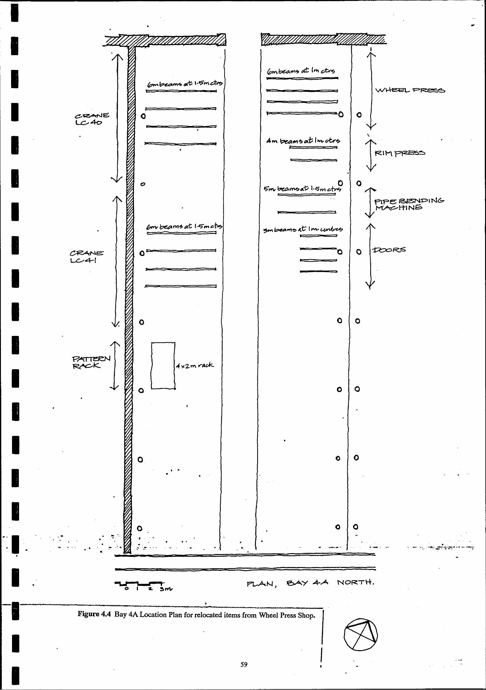
I • ..
•
I I
I ~I::>"",,'!o ~ I.? .... d"~ T I 'M
I J p~ =======o.aO o o
" J •
I •
A .... ~..., ~ ",i; I Mo ~~ ,.. :::::a
.. at •
•
I •
o
I bM-~ M~.at: ,."7"".c.f0.7
• r .,
I O=~--====-=~====I .. , ==--=--"0
I : • a
1
0 0 0
I "P~~
-4 .,. 2. m I'"«d<-~K
I 0 0 0
•
I • •
•
I •
o o o
I • •
• • •
I o o 0
• - . • • • " • I • •• • • • ., • - ~.- •• ~ .~ - - - • • ... --- --. -- - -- .~- .- ---.--.... ~ .. ----.-- .. --~ -• • •
I ! =
eAY A-A NORTH . •
I • *1 ,. . --- '~... le ",,_ = -
Figure 4.4 Bay 4A Location Plan for relocated items from Wheel Press Shop.
I I -" -...
59 I •
~I--~~~~~~~~~~-----'-----------
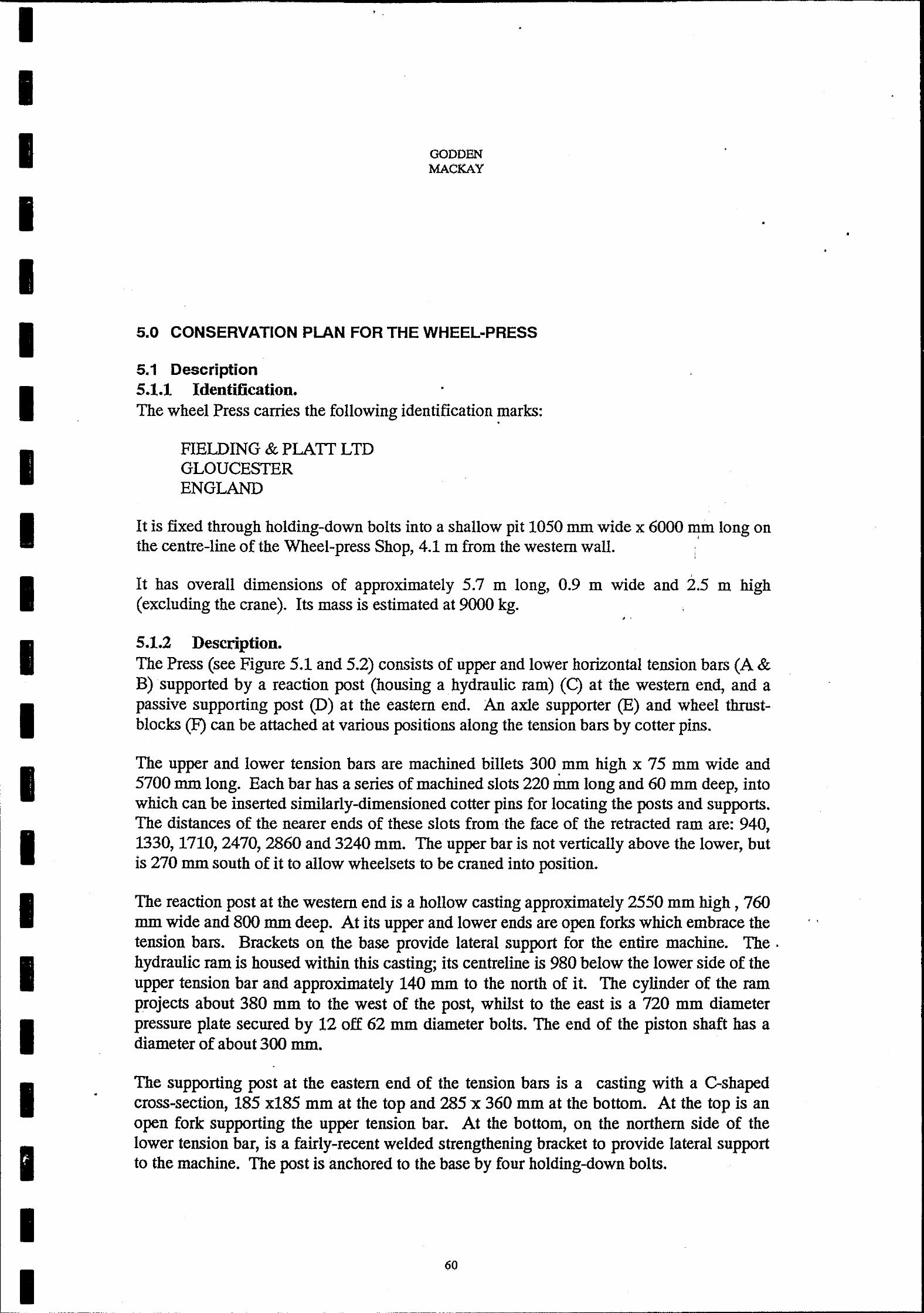
I I I I I I I I I I I I I I I I I I I I I
•
GODDEN MACKAY
5.0 CONSERVATION PLAN FOR THE WHEEL-PRESS
5.1 Description 5.1.1 Identification. •
The wheel Press carries the following identification marks:
FIELDING & PLATT LTD GLOUCESTER ENGLAND
•
•
It is fixed through holding-down bolts into a shallow pit 1050 mm wide x 6000 mm long on , the centre-line of the Wheel-press Shop, 4.1 m from the western wall.
It has overall dimensions of approximately 5.7 m long, 0.9 m wide and 2.5 m high (excluding the crane). Its mass is estimated at 9000 kg.
, .
5.1.2 Description. The Press (see Figure 5.1 and 5.2) consists of upper and lower horizontal tension bars (A & B) supported by a reaction post (housing a . hydraulic ram) (C) at the western end, and a passive supporting post (D) at the eastern end. An axle supporter (E) and wheel thrustblocks (F) can be attached at various positions along the tension bars by cotter pins.
The upper and lower tension bars are machined billets 300 mm high x 75 mm wide and 5700 mm long. Each bar has a series of machined slots 220 mm long and 60 mm deep, into which can be inserted similarly-dimensioned cotter pins for locating the posts and supports. The distances of the nearer ends of these slots from the face of the retracted ram are: 940, 1330,1710,2470,2860 and 3240 mm. The upper bar is not vertically above the lower, but is 270 mm south of it to allow wheelsets to be craned into position.
The reaction post at the western end is a hollow casting approximately 2550 mm high, 760 mm wide and 800 mm deep. At its upper and lower ends are open forks which embrace the tension bars. Brackets on the base provide lateral support for the entire machine. The. hydraulic ram is housed within this casting; its centreline is 980 below the lower side of the upper tension bar and approximately 140 mm to the north of it. The cylinder of the ram projects about 380 mm to the west of the post, whilst to the east is a 720 mm diameter pressure plate secured by 12 off 62 mm diameter bolts. The end of the piston shaft has a diameter of about 300 mm.
The supporting post at the eastern end of the tension bars is a casting with a C-shaped cross-section, 185 x185 mm at the top and 285 x 360 mm at the bottom. At the top is an open fork supporting the upper tension bar. At the bottom, on the northern side of the lower tension bar, is a fairly-recent welded strengthening bracket to provide lateral support to the machine. The post is anchored to the base by four hOlding-down bolts.
60
• •
. .
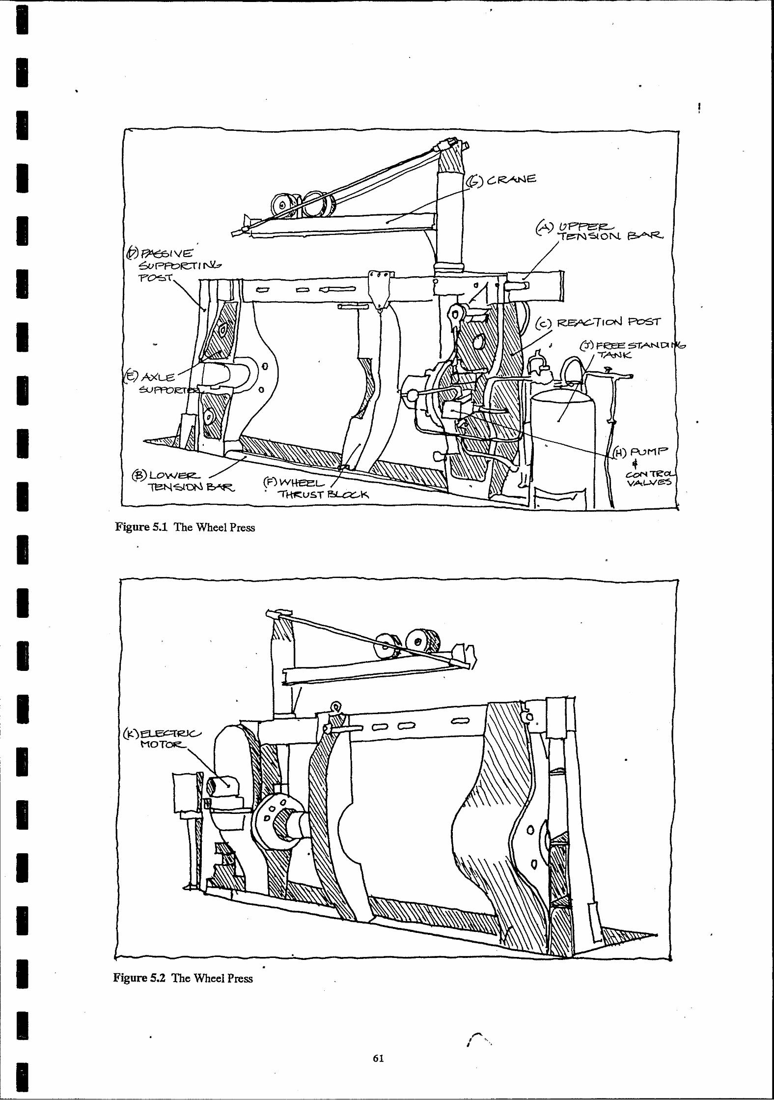
I I I I I I I I I I I I I I I I I I I I I
•
@)LOW~, \BN~'ON~
Figure 5.1 The Wheel Press
(F)W\1eeL-
Figure 5.2 The Wheel Press .
•
,
• ,
•
•
•
,
r", 61

I I I I I I I I I I I I I I I I I I I I
•
GODDEN MACKAY
•
The axle-supporter is a hollow casting of somewhat similar proportions to the western reaction post. It is 780 mm wide and about 750 mm thick at mid-height and has forks and recesses for the cotter pins at top and bottom. At the base it has four 140 mm diameter wheels which enable it to be moved easily in an east-west direction; two are supported on the lower tension bar and two by a track on the base-plate. A pulley is located on the northern face to facilitate this movement. At mid-height is a recess, opening to the north, which receives and supports the wheelset being pressed in the machine; this recess is 280 mm high, with a central section 210 mm long enlarged to 400 high. Machined plates are available which can be inserted into this widened recess to accommodate axles of different diameters. The western face of this recess is about 290 mm from the cotterpin, and the face of the supporter is about 580.
Only one wheel thrust block is presently attached to the machine. It is formed from a single billet of steel, forged and machined to shape. At the upper and lower ends it is approximately 200 mm square, and increases to about 370 x 330 mm at mid-height, where there is a machined recess to accommodate the axle. On its eastern face is a machined recess which would accommodate a 750 mm diameter wheel or gear.
Mounted on top of the western reaction post is a small crane (G). The jib consists of twin 175 mm deep channels, 2440mm long, arranged-back-to-back to form a member having an overall width of 340 mm. At its inboard end, the jib is attached to a vertical king-post at a point 610 mm above the top of the upper tension bar, the lower thrust-bearing of this post is 800 mm below the tension bar. The outer end of the jib is supported by twin 45 mm diameter rods inclined to the top of the king-post 680 mm above the top of the jib. . The crane carriage has four 290 mm diameter wheels which run on the upper flanges of the jib members. ,
The water/air hydraulic system of the press includes a pump and control valves (H) on the front of the reaction post, and a detached free-standing tank (J) to the west. The system is powered by an electric motor (K) mounted on the southern face of the reaction post. This motor drives a pair of eccentrics which operate a two-cylinder reciprocating pump formed in a machined block attached to the northern face of the post. A lever on this block controls the movements of the ram. Water for this pump is supplied from a floor-mounted tank standing to the west of the post. The tank is serviced by three pipes entering from the concrete floor, and a further three pipes connect it to the control box, t9 the pressure end of the hydraulic cylinder and to the reaction end of the hydraulic cylinder. The tank was a type of hydraulic accumulator, water-filled and pressurised by compressed air, used to provide rapid movement of the ram so as to bring it into initial engagement with the work. We have been told that such water/air systems were used in other parts of the works.·
To the south of the tank is a vertical steel tube, embedded in the concrete floor and surmounted by a steel plate. Its purpose and use are unknown.
62
•
•
•
------------------ -----------------------------------------11
I I I I I
I I I I I I I I I
I I I
GODDEN MACKAY
•
5.1.3 Missing or Detached Components.
•
As far as can be ascertained, this machine is complete except for:
One or more wheel thrust blocks and attachments. Pressure gauge.
•
A number of axle plates and other items are presently stored loose around Crane No 41. These include:
Four closed-end hollow cylindrical adaptors (used in pressing wheels onto axles): 210 (outer dia) x 280 (length); 220 x 280mm; 240 x 330mm; 260 x 360mm; and 290 x 510mm.
,
Three hollow tubular adaptors 270 mm diameter, with annular recess at one end: lengths 220, 340, and 400mm. .
Four horse-shoe-shaped axle support plates, approx 390 mm high x 30 mm thick; one square axle-support plate. .
One pair of hinged machined plates, 640 mm outside diameter with a 320 mm interior diameter hole.
Numerous end-caps, plates and bars of unknown purpose.
5.2 Documentary Evidence No documents were located which referred to the wheel press. Only one photograph (undated) shows the top of the inbuilt pedestal crane of the wheel press in the background. All the information concerning the wheel press was obtained by interviewing former workers at Eveleigh. A search of the literature revealed wheel presses of an identical nature although some wheel presses are dealt with in books on workshop technology. It should be noted that with the introduction of diesel locomotives in the 1960s that tyred wheels on tracks and engines were replaced by solid wheels and the Wheel Press Shop was used less and less. A new wheel press was located in the Bay 8 the Wheel Shop about this time.
5.3 Discussion of Significance The wheel press is a turn of the century machine made of massive cast iron sections bolted together and designed to be transported in sections. It is a representative example of an electrically powered hydraulic unit with its own 2 stroke pump and reservoir. With its massive cast and forged components, the press evidences the manufacturing technology current at the turn of the century.
Like many other components in the workshops, the wheel press is British which reflects the new nations dependence on United Kingdom design and supply of railway technology.
63
•
,
I I I I I I I I I I I I I I I I I I
•
,
•
GODDEN MACKAY
The wheel press was once integral to the operations of Eveleigh Railway Workshops and was an active component probably until the late 1960s when it was replaced by a newer machine known as an Archer Wheel Press which was located in Bay 8 South which was known as the Wheel Shop.
The wheel press has its own folklore and former operators, usually fitters, remember the machine with affection.
5.4 Statement of Cultural Significance Aesthetic Significance The wheel press with its massive cast iron and cast steel components is an impressive turn of the century engineering relic.
Technological Significance The wheel press is a representative example of turn of the century design.
The wheel press is a now rare example of an early railway workshop machine.
The wheel press was once an integral part of the operations of the Wheel Press Shop and Eveleigh Railway Locomotive WorkshOps.
Historical Significance The wheel press is over 90 years old and served in the building that bears its name since its
• • • commlss10mng.
Social Significance The wheel press is well known to former workshop workers and is held in high esteem.
•
5.5 Constraints Constraints arising from the Statement of Cultural Significance The wheel press is an item of cultural significance and should be retained and conserved.
All existing fabric associated with the wheel press including tools and other spacing items should be conserved.
Le~kWveConstrmms The Wheel Press in the Wh~el Press Shop are not subject to any conservation instrument issued pursuant to the NSW Heritage Act 1977. The wheel press does fall within the SRA's Eveleigh Heritage Precinct. This precinct is included in that authorities Section 170 Register. The wheel press, however, is not specifically mentioned on that register. The Register is required to list items which could be made subject to a conservation instrument. It is the expectation of the Heritage Council that statutory authorities will take responsibility for appropriate conservation and management of items on their Section 170 Register.
64
•
•
I I
I I I I I
I I
I I I I I
•
,
•
GODDEN MACKAY
,
•
•
•
Under the provisions of REP 26, Amendment 1 Eveleigh Precinct, the wheel press which is in the Wheel Press Shop falls within the area which is sUbject to Master Planning Requirements and the Minister is the consent authority. The Urban Development Plan, City West, requires that conservation plans be prepared for heritage items to determine appropriate and economically viable adaptations. Conservation plans are to address the guidelines for conservation management established in the Conservation Policy for the precinct.
The wheel press is included as a heritage item in the list of additional items identified in the Draft Conservation Policy of Eveleigh prepared by Schwager Brooks Pty Ltd. It is further recommended that these items, at presently located in the Wheel Press Shop, be relocated to Bay 4a in the Main Loco Workshops.
Constraints arising from the physical condition Apart from two missing components, the wheel press appears to be in good physical condition.
Client Requirements The client and other agencies and authorities connected with the railway workshops have made no specific comment concerning the future of the wheel press. However, as the Wheel Press Shop itself is to be demolished it is tacitly agreed that the wheel press itself' will have to be relocated. The wheel press itself was decommissioned some time in the 1960s or 1970s. However, apart from the missing caps to two eccentries, the machine appears to be in good order and condition. It is believed that when complete the machine could be recommissioned. .
5.6 Conservation Policy . The wheel press is not required by the State Rail Authority or any other agency or authority which has an interest in the site. The wheel press has high heritage significance and should be conserved in both the short term and the long term.
It is accepted that the Wheel Press Shop is to be demolished and that the wheel press cannot remain in situ. The short term management strategy is to temporarily relocate the wheel press to the main workshops building in Bay 4A Here it will be preserved with other heritage equipment and will be subject to periodic maintenance and security procedures until it is made available for subsequent display or recommissioning. The long term management strategy is to reconstruct the wheel press as a working relic within the workshop complex.
65
I I I I I I I I I I I I I
I I I I I I I
GODDEN MACKAY
The wheel. press should be dismantled, each component should be labelled with a nondestructible label and the components preserved in workshops Bay 4A A complete list of all components of the wheel press is to be kept with the machine itself, with the SRA Archives, with the Public Works Department and with Godden Mackay. Each component is to be held off the ground, air must be allowed to circulate between the components, the . components are to be sprayed with oil at least every two years and a chain wire fence is to be constructed around the wheel press shop and other equipment removed from the Wheel Press Shop. Details of the dismantling and storage are given in the implementation Section 5.6.
5.7 Implementation 5.7.1 General This section sets out recommendations for the implementation of the Conservation Policy enunciated in the previous section. It is recommended therein that the wheel press be lifted from its present position, and removed to temporary storage in an adjacent building at Eveleigh Railway Workshops.
It must be recognised that work of this nature is extremely delicate, especially when, as here, one is dealing with machinery for which there are no manufacturer's drawings, no installation details, no records of maintenance and no available workmen who have any familiarity with the machine. The task of disassembly and relocation under these conditions is utterly different and far more complex than the relocation of a modem machine within an operating industrial environment. Relocation of this machine will be a . difficult activity, requiring skilled and speCialised techniques and close supervision. For this reason, it is important that this' work not be put to open tender. It is recommended that tenders be invited from a restricted group of contractors.
A procedure for relocation of the wheel press is proposed in the following sections of this report, but it is not intended that use of this procedure be mandatory. Individual contractors in this field have particular items of lifting or transporting equipment, some of which may be especially appropriate for this particular task. It is recommended that considerable flexibility be provided to the tenderers as to the procedure that they intend to adopt; the tenderer should be required to nominate the procedures and equipment that he proposes to use. •
The tender documents should make clear that the contractor shall be held responsible for the safekeeping of the machine at all times during the relocation process; the contractor is responsible for satisfying himself that any procedure that he elects to use will achieve the objective of removing the machine to its new location without damage to the machine.
•
•
66
•

I I I I I I I
I I I I
I I I I I I
• •
GODDEN MACKAY
•
Regardless of what procedure or equipment that the contractor elects to use, it is important that the labelling and component-identification principles embodied in the procedures proposed in this report be followed; it may be some years before the plant is re-assembled after storage, and human memory should not be relied upon for component-identification. Also, where slings are used for hoisting, they shall be attached in such a way and adequately padded so that no damage is done to the machine.
5.7.2 Disassembly Instructions and Labelling There are two optional procedures for re-location of the wheel-press:
(1) Removal of the press as a whole, without disassembly (other than detachment of the hydraulic tank).
(2) Disassembly into major component parts (e.g. tension bars, posts, axle supporter etc) and subsequent removal.
Option 1 is the preferred option on conservation grounds, since it minimises the possibility that components may be mislaid during storage or may be reassembled incorrectly. We have advice that Option 1 also is technically possible, and is probably less expensive than Option 2. We therefore recommend that the press be removed as an entity, after disassembly of the hydraulic tank only. The lift involved is estimated at 9000 kg.
The following disassembly procedure is proposed: •
1. Identify the three pipes that enter the hydraulic Tank from the floor slab; disconnect these at the pipe joints.
•
2. Identify the three pipes that connect the Tank to the Press. Disconnect these pipes by . unscrewing them at the Tank end.
3. Remove the Tank. Attach with tie-wire a metal label bearing the words "Wheel-press".
4. Remove switch-board by cutting through uprights at floor level. Attach with tie-wire a metal label bearing the words "Wheel-press",
5. Identify the Wheel Thrust-block. Remove it from the Press by supporting it from a sling whilst unscrewing the upper retaining bolt. Attach with tie-wire a metal label bearing the words "Wheel-press".
6. Qear all debris from the base of the pit. Identify and slightly loosen the holding •
down-bolts for the main base of the machine.
7. Provide two steel support-beams to which the Press can be bolted to ensure its stability during transportation and storage. Each beam is to be a 150 x 150 x 6 mm SHS, 1800 mm long, drilled for 25 mm bolts at centres appropriate to the holding-down bolts on the Press. Provide 4 off 25 mm 4.6 grade bolts.
8. Lash the small crane to the upper tension beam to prevent it moving during transit.
67
I I I I I I I
I I I I I I I I I I I I
•
GODDEN MACKAY
9. Support the Press from slots in upper tension bar on slings. Undo holding-down nuts attaching the base of the press to the concrete foundation, and lift clear of foundation. Lower onto steel SHS support-beams, and secure with bolts.
10. Collect all steel components stored at base of Pedestal Crane No 41. Provide timber boxes of appropriate size to hold all components, and paint the lids with the words "Wheel-press ll
• Paint/spray all components with Shell ENSIS SDS, and store them in the boxes.
11. The concrete and masonry at the base of the steel cylinder to the western end of the machine should be removed to allow detachment of the cylinder. Attach with tie-wire a metal label bearing the words IIWheel-press 11 •
12. Attach a metal label to the Press identifying the total number of items (packages) stored with the press.
5.7.3 Relocation The Wheel-press and its auxiliary parts are to be removed by transporter to Bay 4A north of the main Workshop, and stored together in the location shown on the plan. (See Figure 4.4).
5.7.4 Conservation Measures The components of the wheel press are to be laid on a series of four timber or steel beams spaced at 1.5 metre intervals or otherwise suitably placed in Bay 4A of the main workshops adjacent to the components of the two large cranes.
The components should be an:anged in such a way that they do not cause damage to adjacent parts. Care should be taken especially with cast iron components to ensure they are not placed in tension and are placed in a stable position. All components of each machine should be placed in a single discrete unit.
Small components such as nuts and bolts should be refastened in the holes from which they were removed and not placed in a separate reciprocal unless this is absolutely n~essary. All components of the wheel press should be labelled as described and when all are together all should be chained together to prevent separation. Where small components have been removed to facilitate relocation, they should be refastened when relocation is complete.
As each component is laid in its new position it should be painted or sprayed with Shell ENSIS SDC. Electrical components should not have oil sprayed on them. When all components of all machines are in place, a chain wire fence should be constructed around the components. This will allow circulation of air and will prevent vandalism· and pilfering.
5.7.5 Reassembly Instructions Reassembly, if required, consists of: removing the temporary support-beams, bolting the Press to its new foundation, and reconnecting the pipes from the tank to the Press.
68
----------------------------------------"
I I I I I I I I I I I I I I I I I I I I I
•
,
GODDEN MACKAY
6.0 CONSERVATION PLAN FOR THE RIM PRESS
6.1 Description 6.1.1 Identification. The Rim Press carries the following identification marks:
B & S MASSSEY LTD MANCHESTER ENGLAND
REFERENCE NUMBER M212 N01
SOLE AGENTS MARFLEET & WEIGHT PTY LTD ENGINEERS MELBOURNE
NSWTD HT 3753 SO
It is fixed by holding-down bolts to a foundation near the south wall of the Wheel Press Shop 15.3 m from the western wall of the shed, with its longitudinal axis orientated north-
south.
Its overall dimensions are approximately 1.75 m wide, 2.5 m long and 1.9 m high
(excluding motor).
Its mass is estimated at 4000 kg.
6.1.2 Description. The press (see Figure 6.1 and 6.2) consists of an upright chassis housing a drive mechanism and hydraulics, and a set of horizontal wheel-support arms near floor level.
The chassis is 1240 mm long and 830 mm wide and stands 1460 mm high. The chassis in in two sections: a hollow base, 1300 high, of cast ferrous material with a wall thickness of
40 mm; and a ferrous cap 160 mm high.
69
• .
•
I
I I I I I I I I I I I I I I
•
•
•
Figure 6.2 The Rim Press
70 •
Figure 6.1 The Rim Press
~Oll-PUMF
•
•
•
I

I I I
I I I I I I I
I I I I I
I I I
•
,
GODDEN MACKAY
The chassis cap consists of two castings, the northernmost of which incorporates a hydraulic cylinder (A) at its front (northern) end; the cylinder has an outer diameter of 320 mm and an overall height (from the lower surface of the cap) of 220 mm. The upper capplate of the cylinder is fixed by 6 bolts, and was surmounted by a pressure-gauge in a metal shroud; the gauge is no longer present. To the rear of the ram is a combined control valve and lubrication reservoir (B), standing 340 mm high above the cap and operated by a control wheel mounted on a vertical spindle on the western side of the chassis. The main drive motor (C) is mounted to the rear of this.
The chassis base is bolted to a concrete foundation plinth by an angle' cleat at the rear and by a single bolt at each side at the front. On the western side of the chassis base, 750 mm from the front and 620 from the top, is an inspection plate about 450 mm in diameter attached by 6 bolts. An oil pump (D), driven by eccentrics from the main drive-shaft, is mounted towards the rear of the western face, and a supply pipe connects to the control valve. On the eastern side of the chassis is a 1060 mm diameter flywheel driven by the main motor by means of an enclosed belt (E). Within the chassis are the drive shafts for the rim-pressing operations.
•
On the front or northern side of the chassis, 270 mm below the lower surface of the cap, is a pressure wheel (F) approximately 300 mm in diameter, standing about 125 mm proud of the face of the chassis. The wheel is mounted ona block, able to be moved downwards along guides by the hydraulic ram; in its uppermost position, the wheel has its axis inclined slightly upwards from the horizontal. Directly beneath the pressure wheel, 580 mm beneath the cap, is a small idler wheel (G), mounted with its axle vertical. Beneath that again, 780 mm below the cap and 125 mm proud' of the face of the chassis, is a drive wheel (H) mounted on a horizontal axle.
Two castings are attached to the front face of the chassis near floor level. Each of these consists of two arms, one perpendicular to the longitudinal axis of the chassis, and one at 300 to it. The perpendicular arm is 650 mm long and 230 mm wide. It supports a bollard carrying an unrimd idler whe(}l (J), 230 diameter and 80 mm high, mounted with its axle vertical; this wheel is somewhat higher than the idler wheel on th~ front of the chassis, and during operation it was probably in contact with the rim of the rolling-stock wheel. The position of the bollard can be adjusted in the arm by means of a single screw-shaft and wheel, to suit wheel rims of various diameters.
The arm at 300 to the axis of the chassis is 1100 long and 255 mm wide, It also supports a bollard which carries a 220 mm diameter flanged idler wheel (K) mounted with its axis horizontal; the height of this wheel above the plinth is the same as that of the drive wheel mounted on the front of the chassis. This wheel also can be adjusted in its supporting arm by means of a threaded bar and crank to suit rims of various diameters .
6.1.3 Missing Components: As far as can be ascertained, this machine is complete except for one pressure gauge.
71
•
•
•
•
•
I I I
I 'I I I I I I I I
I I I
6.2 Documentary Evidence
GODDEN MACKAY
•
No documents were located which referred to the rim press. The ouly photograph of the Wheel Press Shop shows the hydraulic chain testing machine in the position in which the rim press now occupies. It would appear that the rim press was in fact installed in the Wheel Press Shop some time after the rest of the equipment.
A search of the literature inclUding general literature has failed to identify rim presses of this type. However, SRA documents have given an indication of the way in which this press worked. (Wheel and Axle Manual, 1956; see Figure 2.15)
6.3 Discussion of Significance . The rim press, like the other earlier equipment in the Wheel Press Shop, is a massive cast
steel and tool steel structure which is representative of examples of turn of the century engineering equipment.
Although the way in which the rim press operates is not as evident as the way in which the crane or the wheel press operates it is still a relatively easily interpreted engineering relic. The rim press is British made which reflects the new nations ties to the United Kingdom for their rail and ~ngineering technology. We found no former employees who had actually operated the rim press. The rim press was not held in the same esteem as either the wheel press or the cranes. The rim press however appears to be in sound and operating condition. Many of the components of the rim press are covered with a dusting of rust but this does not in any way affect its performance.
. 6.4 Statement of Cultural Significance Aesthetic Significance The rim press is an impressive example of a railway workshop engineering relic.
Technological Significance' The rim press is representative of the types of machine which were manufactured before the First World War and is now a rare example of early railway technology. The rim press was an integral part of the operations of the Wheel Press Shop and of Eveleigh Railway Workshops.
Historical Significance The rim press has been associated with the operations of the railway workshops for a number of decades.
Social Significance The rim press is known by former workers to be an integral part of the Wheel Press Shop.
•
72
•
I I I I I I I I I I I I I I I I
I I I I
•
----------~------ ~---.------------------~. ~---.- -~- ---------- --, ,
•
6.5 Constraints
GODDEN MACKAY
Constraints arising from the Statement of Cultural Significance The rim press is a relic of some cultural significance and should be retained and conserved either in situ or relocated. The existing fabric of the relic should be preserved and maintained.
Legislative Constraints . The rim press in the wheel press shop is not SUbject to any conservation instrument issued pursuant to the NSW Heritage Act 1977. The rim press does fall within the SRA's Eveleigh Heritage Precinct. This precinct is included in that authorities Section 170 Register. The rim press, however, is not specifically mentioned on that register. The Register is required to list items which could be made subject to a conservation instrument. It is the expectation of the Heritage Council that statutory authorities will take responsibility for appropriate conservation and management of items on their Section 170 Register.
. ' Under the provisions of REP 26, Amendment 1 Eveleigh Precinct, the rim press which is in the Wheel Press Shop falls within the area which is subject to Master Planning Requirements and the Minister is the consent authority. The Urban Development Plan, City West, requires that conservation plans be prepared for heritage items to determine appropriate and economically viable adaptations. Conservation plans are to address the guidelines for conservation management established in the Conservation Policy for the precinct.
The rim press is included as a heritage item in the list of additional items identified in the Draft Conservation Policy of Eveleigh prepared by Schwager Brooks Pty Ltd. It is further recomrnende~ that these items, at presently located in the Wheel Press Shop, be relocated to Bay 4a in the Main Loco WorkshOps .
•
Constraints arising from physical condition There appears to be no factual problems associated with this machine.
Client requirements ~ The client has made no specific recommendations concerning the future management of this relic. However, it is known that the client and other agencies and authorities involved with the site wish to have the Wheel Press Shop site cleared and hence the rim press should be relocated and conserved.
The rim press was decommissioned some time before the Wheel Press Shop closed. However, it is believed that the condition of the rim press is such that if the power source was reconnected the press could be recommissioned.
•
73
•
I I I
I I I I
I I I I I I I I I I I I
6.6 Conservation Policy
GODDEN MACKAY
•
The rim press is not required by the SRA or any of the agencies associated with the site. The rim press has some heritage significance and rarity and should be conserved and made secure.
It is accepted that the Wheel Press Shop is to be demolished and that the rim press cannot remain in situ and will be relocated. The most appropriate place for temporary relocation before recommissioning is in the main workshop building in Bay 4A. Here they will be preserved with other heritage equipment and with appropriate conservation and security procedures will be available for subsequent recommissioning.
The rim press should be dismantled, each component labelled with a non-destructible label and the components preserved in the workshops. A complete list of all components of the press is to be kept with the rim press itself, with the SRA Archives, with the Public Works Department and with Godden Mackay. All components must be held off the ground, air must be allowed to circulate between the components, the components are to be sprayed with oil every two years and a chain wire fence is to be constructed around the components and the components of other relics removed from the Wheel Press ShOp. Details of the dismantling and storage are given in the Implementation Section 6.7.
6.7 Implementation 6.7.1 General This section sets out recommendations for the implementation of the Conservation Policy enunciated in the previous section. It is recommended therein that the rim' press be lifted from its present position, and removed to temporary storage in an adjacent building at Eveleigh Railway Workshops.
It must be recognised that work of this nature is extremely delicate, especially when, as here, one is dealing with Jllachinery for which there are no manufacturer's drawings, no installation details, no reCords of maintenance and no available workmen who have any familiarity with the machine. The task of disassembly and relocation under these conditions is utterly different and far more complex than the relocation of a modem machine within an operating industrial environment. Relocation of these machines will be a difficult activity, requiring skilled and specialised techniques and close supervision. For this reason, it is important that this work not be put to open tender. It is recommended that tenders be invited from a restricted group of contractors.
A procedure for relocation of the rim press is proposed in the following sections of this report, but it is not intended that use of this procedure be mandatory. Individual contractors in this field have particular items of lifting or transporting equipment, some of which may be especially appropriate for this particular task. It is recommended that considerable flexibility be provided to the tenderers as to the procedure that they intend to adopt; the tenderer should be required to nominate the procedures and equipment that he proposes to use.
74
--- ---------------
,
•
•
•
•
I' I I I I I I I I I I I I I I I I I
I
•
•
GODDBN MACKAY
•
•
•
The tender documents should make clear that the contractor shall be held responsible for the safekeeping of the machine at all times during the relocation process; the contractor is responsible for satisfying himself that any procedure that he elects to use will achieve the objective of removing the machine to its new location without damage to the machine.
Regardless of what procedure or equipment that the contractor elects to use, it is important that the labelling and component-identification principles embodied in the procedures proposed in this report be followed; it may be some years before the plant is re-assembled after storage, and human memory should not be relied upon for component-identification. Also, where slings are used for hoisting, they shaJI be attached in such a way and adequately. padded so that no damage is done to the machine.
6.7.2 Disassembly Instructions and Labelling The following disassembly procedure is proposed:
1. Ensure that the chassis and wheel support arms are not cast into the concrete foundation on which they sit. If they are they must be carefully detached.
2. Ensure that the pump and pump-cover on the western side of the machine are not attached to the concrete foundation; if so, detach them.
3. Undo the four bolts that attach each wheel support arm to the chassis. Attach the bolts to the arm by tie-wire. Attach with tie-wire a metal label bearing the words "Rimpress" .
3. Lift each arm on to the transporter.
4. Undo the four holding-down bolts that attach the chassis to its foundation-plinth. Lift •
the chassis onto the transporter.
5. Remove the control panel from the south wall of the building (to the rear of the Press). Attach with tie-wire a metal label bearing the words "rim press".
. 6. Attach a metal label to the Press identifying the total number of items (packages)
stored with the press.
6.7.3 Relocation The rim press and its auxiliary parts are to be removed by transporter to Bay 4 North of the main Workshop, and stored together in the location shown on the plan. (See Figure 4.4).
6.7.4 Conservation Measures The components of the rim press are to be laid on three timber or steel beams spaced at one metre intervals suitably placed in Bay 4A of the main workshops. Bay 4A is the most appropriate as it is clear of other machinery and is served by an overhead crane.
,
75
•
•
•
•
•
•
I I I I I I I I I I
I I I I I I I
•
•
•
GODDEN MACKAY
,
The components should be arranged in such a way that they do not cause damage to adjacent parts. Care should be taken especially with cast iron components to ensure they are not placed in tension and are placed in a stable condition. All components of each machine should be placed so as to form a single discrete unit.
Small components such as nuts and bolts should be fastened in their original holes and not placed in a separate reciprocal unless this is absolutely necessary. All components should be labelled as described and all should be chained together to prevent separation. Where small components have been removed to facilitate relocation they should be refastened when relocation is complete.
As each component is laid in its new position any rust, especially surface rust, should be· lightly painted with phosphoric acid. This should be followed by a painting or spraying with Shell ENSIS SDC. Electrical components should not have oil sprayed on them. When all components of all machines are in place, the chain wire fence should be constructed around the components. This will allow circulation of air and will prevent vandalism and pilfering.
6.7.5 Reassembly Instructions Reassembly, if required, consists of: bolting the Press to its new foundation; attaching the wheel-support arms; reconnecting the control board .
•
•
•
•
76
•
,
I I I I I I I I I
I
I I I I
•
•
GODDEN MACKAY
7.0 CONSERVATION PLAN FOR THE PIPE BENDING PRESS
7.1 Description 7.1.1 Identification The pipe bending press carries the following identification marks:
HENRY BERRY & CO LTD . LEEDS
No 872 NSWGR CLASS BP •
It was formerly located in the Coppersmiths Shop, and was connected to the 700 psi water hydraulic power system, the motors for which were in the annexe at the south end of Bay 4. Marks on its lower sides indicate that it was never bolted to its foundation, but that concrete was cast around its base. At the time of preparation of this report, the press was stored in the south-east corner of the Wheel-press Shop.
•
Its overall dimensions are 2.2 m wide, 2.6 m long and 0.6 m high.
Its mass is estimated at 5000 kg.
7.1.2 Description The pipe bending press ( see Figure 7.1) consists of a cast ferrous chassis (A) to which are . attached two hydraulic rams (B & C) and two anvils or reaction blocks (D).
The chassis has a transverse width of 2200 mm and longitudinal dimensions of 1430 mm on the centre line and 880 mm at the sides. It stands 620 mm high and is a hollow casting with a wall thickness of 50 mm. Provision exists for four holding down bolts, but none are presently in place. The upper horizontal surface has two recesses formed in the casting, one housing the anvils and anvil adjustment screws, and the other accommodating the hydraulic rams and bend-former. Both of these recesses have machined surfaces forming dove-tail keyways to guide the movements of the anvils and the bend-former.
The two anvils (D) each stand 390 mm above the upper surface of the chassis. They consist of rectilinear block castings, machined on three vertical faces to produce horizontal curved surfaces able to accommodate pipes of different diameters. This casting is supported in a housing so that it can be rotated about a vertical axis as the bending of the pipe requires. The lower part of the housing has machined surfaces that engage in the 380 mm-wide keyways in the chassis, which permits the distance between the anvils to be adjusted to suit different radii of bend of the pipe. Adjustment is controlled by a pair of square-threaded 75 mm adjustment bolts, operated from the sides of the chassis. Removable sheet-metal coverplates protect the key-ways and adjustment bolts.
•
77
•
•

I I I I I
I I
I
I I I
... -- ... .,
•
•
, , I
• ..
•
•
.' • • • " • • • ,
Figure 7.1 The Pipe Bending Press -- .. .. - .... ~
Figure 7.2 Pipe Bending Press •
. '
,-•
~ • • . ' , • • -, -. '~ , ,
~
• I .. .-~
f' • _ .. .. "f · .... , ..... {.' · ')' ,
. ":'\ I,
•
..SI I '"11
--'>-
.' .
-•
•
78
• •
_ .. _--- -_ ... _-
•
,. . • , •
•
•
-• • • • • •
• " ,
I I I I I I I I I
I I I
I I
•
•
•
GODDEN . MACKAY
•
The main hydraulic ram (B) is attached to the rear of the chassis by two 110 mm diameter threaded bars and nuts (F). It consists of a cylinder 890 mm long and 490 mm outer diameter, supported by a lug at its rear end which would rest on the machine's foundation. A 450 mm packing gland, attached by 8 off 32 mm diameter bolts, seals the piston rod, which has its centre-line 190 mm below the upper surface of the chassis. The 250 mm diameter piston rod and the retainer (G) for the bend-formers are a single forging; which projects 260 mm above the upper surface of the chassis. A dovetail keyway is machined in the vertical face at the end of this forging; it is assumed that bend-formers of different diameters could be locked into this keyway, although no formers are presently stored with the, machine. The forging is guided in its longitudinal movement by machined surfaces which engage in corresponding keyways machined into the longitudinal recess in the chassis. At the front end of this recess is a smaller hydraulic ram (C), 150 mm diameter and 730 mm long, which pushes against the front end of the main piston to return it to its cylinder after a pipe bending operation has been completed.
7.1.3 Missing Components. The machine as examined appears to lack the following components:
(a) Bend-formers. It would be expected that the machine would have used several different bend-formers to suit various diameters of pipe and radius of bend; no formers are stored with the machine.
(b) Anvils. One set of anvils is attached to the machine; it is possible that other anvils •
were a\milable originally to suit other pipe diameters. •
•
(c) The adjustment screws for the anvils terminate in square ends; no crankS or handles are presently stored to turn these screws.
(d) No valves or controls for connection to the hydraulic supply system are stored with the machine.
7.2 Documentary Evidence Despite a thorough search of the SRA Archives and the assembled material of Godden Mackay no information was found concerning the age, date of installation, operations or previous uses of the pipe bending press. Similar bending presses occur in the literature although no details of their operation is given. Any information used in this report was supplied by Jack Bruce, former supervisor of the locomotive workshops and former coppersmith retired.
79
•
I I I I I I I I I I I I I I I I I I I I
------- --
•
7.3 Discussion of Significance
GODDBN MACKAY
The pipe bending press is a turn of the century machine made of massive cast iron sections. It is a representative example of those hydraulically powered unit which -employed extremely simplified technology in their operation. The pipe bending press was manufactured by Henry Berry & Co of Leeds and is of British manufacture which indicates the reliance of the new nation on the railway technology of Great Britain. The pipe bending press was once integral to th~ operations of the Eveleigh Railway Workshops and was an active component probably until the time the workshops closed. The wheel press like many other machines had its own folklore which grew up around it and the previous operatorsview the machine with a great deal of affection. Because of its simplicity, it was practically maintenance free and operated without breakdown for decades.
•
7.4 Statement of Cultural Significance Aesthetic Significance
-
The pipe bending press with its massive cast iron base and cast iron cylinders is an impressive turn of the century railway engineering relic.
Technological Significance . The pipe bending press is a representative example of turn of the century railway engineering design and is a now rare example of a railway workshop machine. The pipe bending press was once an integral part of the operations of the coppersmiths shop and the Eveleigh Railway Workshop. .
Historical Significance The pipe bending press is believed to be over 90 years old and operated in building C or the coppersmiths shop which is adjacent to the Wheel Press ShOp.
Social Significance . The pipe bending press is well known to former workshop workers and is held in high esteem. •
7.5 Constraints Constraints arising from the Statement of Cultural Significance The pipe bending press is a relic of some cultural significance and should be retained and conserved. The existing machine fabric should be preserved and maintained.
Leg~kWveConstrmms The pipe bending machine in the Wheel Press Shop is not subject to any conservation instrument issued pursuant to the NSW Heritage Act 1977. The pipe bending machine does fall within the SRA's Eveleigh Heritage Precinct. This precinct is included in that authorities Section 170 Register. The pipe bending machine, however, is not specifically
•
80
•
•
•
•
! • , ~
t , I I I

I I I I I I I
I I I I I I I I I I I I
•
•
•
•
GODDEN MACKAY
mentioned on that register. The Register is required to list items which could be made subject to a conservation instrument. It is the expectation of the Heritage Council that statutory authorities will take responsibility for appropriate conservation and management of items on their Section 170 Register.
Under the provisions of REP 26, Amendment 1 Eveleigh Precinct, the pipe bending machine which is in the Wheel Press Shop falls within the area which is subject to Master Planning Requirements and the Minister is the consent authority. The Urban Development Plan, City West, requires that conservation plans be prepared for heritage items to determine appropriate and economically viable adaptations. Conservation plans are to address the guidelines for conservation management established in the Conservation Policy for the precinct.
The pipe bending machine is included as a heritage item in the list of additional items identified in the Draft Conservation Policy of Eveleigh prepared by Schwager Brooks Pty Ltd. It is further recommended that these items, at presently located in the Wheel Press Shop, be relocated to Bay 4a in the Main Loco Workshops.
Constraints arising from physical condition The pipe bending press is in good physical condition and no structural problems are evident.
Client requirement The client has expressed no specific requirements concerning the pipe bending machine. However, the client and other agenCies and authorities involved with the site wish to remove the Wheel Press Shop. This means that the pipe bending machine will have to be relocated.
7.6 Conservation Policy. '. The pipe bending press has some heritage significance and because of its rarity should be conserved and made secure .
•
It is accepted that the Wheel Press Shop is to be demolished an~ that the pipe bending machine will have to be relocated. The most appropriate place for temporary relocation is in the main Locomotive Workshops building in Bay 4A Here the pipe bending press will be maintained along with other heritage equipment and appropriate maintenance and security procedures wiU be available prior to its subsequent recommissioning.
81
--.-.
I I
I
I I I I I I I I
I I I I
I I I
I
•
I
GODDEN •
MACKAY
The pipe bending press should be moved if possible in one piece. It is believed that there are no other components belonging to this press. The press must be placed in such a way that it is not in contact with the ground, air must be allowed to circulate between this machine and the components of other machines stored in the same place and the machine is to be sprayed with oil every two years. A chain wire fence is to be constructed around this machine and other machines which have been removed from the Wheel Press Shop. Details of the moving and storage are given in the Implementation Section 7.7.
7.7 Implementation 7.7.1 General This section sets out recommendations for the implementation of the Conservation Policy enunciated in the previous section. It is recommended therein that the pipe bending press be lifted from its present position, and removed to temporary storage in an adjacent building at Eveleigh Railway Workshops.
It must be recognised that work of this nature is extremely delicate, especially when, as here, one is dealing with machinery for which there are no manufacturer's drawings, no installation details, no records of maintenance and no available workmen who have any familiarity with the machine. The task of relocation under these conditions is utterly different and far more complex than the relocation of a modem machine within an operating industrial environment. Relocation of these machines will be a difficult activity, requiring skilled and specialised techniques and close supervisiqn. For this reason, it is important that this work not be put to open tender. It is recommended that tenders be invited from a restricted group of contractors.
A procedure for relocation of the pipe bending press is proposed in the following sections of this report, but it is not intended that use of this procedure be mandatory. Individual contractors in this field have particular items of lifting or transporting equipment, some of which may be especially appropriate for this particular task. It is recommended that considerable flexibility be provided to the tenderers as to the procedure that they intend ~o adopt; the tenderer should be required to nominate the procedures and equipment that he proposes to use.
The tender documents should make clear that the contractor shall be held responsible. for the safekeeping of the machine at all times during the relocation process; the contractor is responsible for satisfying himself that any procedure that he elects to use will achieve the objective of remOving the machine to its new location without damage to the machine.
Regardless of what procedure or equipment that the contractor elects to use, it is important that the labelling and component-identification principles embodied in the procedures proposed in this report be followed; it may be some years before the plant is re-assembled after storage, and human memory should not be relied upon for component-identification. Also, where slings are used for hoisting, they shall be attached in such a way and adequately padded so that no damage is done to the machine.
82
•
I I I I
I I I I I I I I I I
I I I
•
GODDEN MACKAY
7.7.2 Disassembly Instructions and Labelling Because this machine has already been removed from its original location in the Coppersmith's Shop, no further disassembly is required.
The two sheet metal covers to the anvil adjustment screws are to be securely attached to the chassis using soft tie-wire.
7.7.3 Relocation The Pipe-bender and its auxiliary parts are to be removed by transporter to Bay 4Anorth of the main Workshop, and stored together in the location shown on the plan (Figure 4.4).
7.7.4 Conservation Measures The pipe bending machine is to be laid on timber or steel beams suitably placed in Bay 4A of the main workshops. The pipe bending machine should be placed in such a way that it does not cause damage to adjacent stored heritage machinery. Care must be taken to place it in a stable position.
When in place the pipe bending machine should be painted or sprayed with Shell ENSIS Snc. A chain wire fence should be constructed around the assembled relics. This will allow circulation of air and will prevent vandalism and pilfering.
7.7.5 Reassembly Instructions As this machine is to be moved without disassembly, reassembly will not be required.
•
•
•
83
L---~~~~~~~~~~~~~ _____ _
•
•
,
. .
I I I I I I I I I I I I
I I I I I I I
•
GODDBN MACKAY
•
8.0 CONSERVATION PLAN FOR THE DOORS OF THE MAIN WORKSHOPS
8.1 Description 8.1.1 Identification The doors to the main bays of the Loco Workshops building have been removed and stored in the Wheel Press Shop. They were replaced with chain wire gates when Paddys Markets
,took up residence. The reason for removing the doors was to prevent them from being damaged and it was also felt that the other doors would provide easier access as well as more light and ventilation for market activities. The doors from the workshops viere stored one on top of the other in the Wheel Press Shop with spacing boards between them. It should be noted that the spacing boards were not all of the same thickness and some of the doors are now bowed. In some cases this bowing is excessive. Most of the doors still appear to be in useable condition.
8.1.2 Description . The original doors were constructed as framed double doors to be hung on either side of a round headed or semi-circular arched doorway about 3 metres wide and 4.5 metres high of which there were 14 in the south side of the main workshops. There are two doors which are of the normal rectangular shape which were attached to Bay 10.
The doors, as designed, had a long hanging stile and a short hinged stile, a bottom rail and two intermediate rails. The quadrant head of each door was often made from a single piece of timber scarfed into the hinge stile about 600mm below the arch.
The doors were panelled with diagonally laid tongue and grooved pine laid up from the hanging rail which provided a flush external finish. There were two braces fitted internally to the door. The door furniture consisted of two hinges with forked blades which were bolted on both sides of the door. Gudgeon pins were set in steel brackets into the internal reveal. Most doors were fitted with a bale bolt on their lower end and a top locking bolt which was provided with a locking handle lever at the 1.5 metre height. Some of the doors had smaller access doors or pedestrian doors cut in to one of the main doors close to the hanging style. .
8.1.3 Missing or Detached Components It was not possible to manually lift any door in order to inspect it. Hence, a full investigation was not possible of any of the doors. A forklift was obtained for the purpose of lifting the doors, however, access was not possible to the Wheel Press Shop owing to the existence of two chain wire fences.
It would appear that most doors have some components missing from them but this can only be ascertained when they can be individually inspected.
• • •
84
f
,
I
I I I I I I I I I I I I I I I I I I I I
GODDBN MACKAY
Some of the doors appear to be completely rebuilt and contain little of their original door furniture. Some are constructed of almost entirely new timber and are sheathed in corrugated iron. Others appear to retain their original fabric while others retain some of their original fabric and have either been sheathed in corrugated iron or have had other lengths of timber incorporated into their structure.
8.2 Documentary Evidence The doors appear in numerous photographs and are the same doors as in the Carriage Works, of which we have original drawings. (See Figure 8.1). While some of the doors have been altered, some even rebuilt, there is no documen.tary evidence of these changes.
8.3 Discussion of Significance The doors are integral parts of the fabric of the Eveleigh Railway Locomotive Workshops and hence are of equivalent heritage status when they are composed of original material. Further discussion is not possible until the doors can be individually inspected.
8.4 Statement of Significance A Statement of Significance is not possible until the doors can be individually inspected.
8.5 Constraints A series of constraints cannot be provided until the doors can be individually inspected.
8.6 Conservation Policy A Conservation Policy cannot be prepared for the doors until they can be inspected. All that can be done in this report is to give a short term policy which will allow them to be preserved in their present condition.
The doors must be taken and stored in secure surroundings in Bay 4A of the locomotive workshops. The doors must not be reinstated until each is inspecte4 and a Conservation Plan prepared for it.
Any future Conservation Plan will depend on:
(1) (2) (3) (4)
the condition of the door its proposed future function its relation to other equipment in the workshop where it is located the functioning of the workshop Bay within which the door is located .
•
85
•
•
•

I I I
I I I I I I I I .1 I I I I I I I
11
8.7 Implementation
,
GODDEN MACKAY
,
•
Two separate sets of at least three parallel timber or steel beams should be laid in the workshop Bays 1-4A and made level. The doors should be laid on each of these to form two stacks. Between each door there should be a second set of beams laid in such a way that the door on top remains parallel to the one below. In some cases, because of the configuration of the doors, these beams will not be contiguous. Doors may be placed one on top of the other so long as the doors below are not being damaged.
It should be noted that this process must be closely supervised. The process of stacking the doors may be likened to stacking timber to seasoning. .
No doors should be reinstated before maintenance has been carried out. Where doors are in a condition where they cannot be used a replacement door may be reconstructed. This door will conform to the provisions of a Conservation Plan prepared for workshops Bays 1-15.
,
, ,
• •
• •
•
•
86
I

L • •
-/ • • "" . .'
, !
, • -, "
•
,
.. ""_. I •• ~' · ';. ... ~: <j.", '"
I'· ~ '. "
.,.. , •
" , , -, • · i • · r' ,
",I: .. ~ ... " ~. ,
•
• • I • , I' '",
j ( · , , •
• • •
• •
•
'.
, •
•
• , •
•
• • ... • ~tl
:'--_...: •
• • -• l. • •
•
- "
i I
•
! .. - ,'1
-rrf I •
• , •
• -.-
-"'DU '''DYlpM _ Il.tunal_ .... c,1OQ!II DrCltQMa-"
_kM, ,_,._fnt-
... ~~~--------------.~ ;0. _ JltJ'rO!l " ue' g-
• --•
...... "j -.
-lIl!ILor~-- .... ~-.,....-"
•
,
•
•
•
•
• •• ',. •
1-
UUlgN 0" 1I101' u-,
, •
Figure 8.1 Drawing, New Workshops, Eveleigh. Details of doors, windows and shops 16 to 25 •
--.--- .. - _' __ M - ~ ...
,
!.-. - •
•
• "~-.uU1»1I Qft Lt.' 11-
" , •
,
87
,
.'.
11
, " i I , ~:' J~' ~
j . .. 'I, I I
•
• ,
•
•
. " .. " •
-
• ,
• •
, \0 ... __ .. "
.... ---1 • ,~, .. ~'I'''''''~
r-~--' , r=.:;;'iliQ' ~ 9 ' -, "
- ". , -
• I / • .
- ••• I .. r"r.~.", -!-.lou-
" • • " ,'OftAWINC N2 4
• • " j
"' u .,
• • .. •
.- .... ---'""""' .... - ..... ~ ......... --~'"' .... - ""'
•
--- k!:II.A' ...... t, , ......... - '--l.w ~
•
•
-'--- .... " , r'F;
• jEll ! t ,! I
•
I- -• \_ .. -
•
•
• , ! • • ; • I !
'f(;;:r ., .".,
di, 'tt!
,
-' '--_ •• , ............. AT i"'..... ~J .. 'XC"_-_
,
• • !
•
• , , • • • • • ,
V: • •
• <. "
•
•
I
I I I I
I I I I I
I I I
•
,
•
GODDEN MACKAY
9.0 CONSERVATION PLAN FOR THE PATIERNS
9.1 Description 9.1.1 Identification
•
There are at present a series of patterns located in the south west corner of the Wheel Press Shop on four separate shelves of a large pattern storage bin.
9.1.2 Description The patterns are all in fair condition although some of them show signs of cracking. In the main they appear to be core patterns which had been stored here because of their rarity value. There is no indication on the patterns of the items they were used to produce and although they bear the railway pattern numbers these pattern numbers now have no meaning at all, as the cards were destroyed when Eveleigh was closed in 1988.
9.2 Documentary Evidence No documentary evidence concerning the patterns exist.
9.3 Conservation Policy The patterns have some significance as they were associated with the operations of the workshops. It is unlikely that their significance can ever be proved. However, until such time that the space is required these patterns should be stored in the workshops Bay 4A with the other material removed from the Wheel Press ShOp.
•
9.4 Implementation There is no apparent order to the patterns at the moment and while this study has been underway the patterns have been taken from some of their resting places, placed on the floor and then replaced haphazardly on the racks. It is recommended that the patterns be stored either on pallets or on racks which may be especially constructed for them.
There are no specific conservation methods to be applied to these patterns.
•
•
88
I I I I I I I I I I I
I I I I I I I
•
•
GODDEN MACKAY
1 0.0 CONSERVATION PLANS FOR HOISTS
10.1 Description
,
There are two simple jib hoists with horizontal jibs and diagonal stays attached to the columns on the south side of the workshops.
These particular hoists appear to have been placed there relatively recently and there are no signs that they were ever part of a hydraulic or pnematic hoisting system. It is believed that they were relocated from some other part of the workshop. It is almost certain they were operated with small hand or electric block and tackle units.
There are numerous other examples in the same condition scattered through Bay 4A. It is not believed that these items will help with the interpretation of the workshops.
These items may be scrapped.
•
• •
89
•
-:::-------:-. --------------------------------- -_. ---------,
I I I I I I I
I I
I I I I I I I I I
. .
• •
GODDBN MACKAY
11.0 CONSERVATION POLICY FOR OIL TANKS
11.1 Description 11.1.1 Identification
•
There are two very large oil reservoirs outside the former Potash Shop which are probably 7.5 metres high and 1.4 metres in diameter. These massive tanks were once large receiver tanks for Babcock and Wilcox, water tube boilers. They are of riveted construction in three sections. The upper and lower sections are slightly larger in diameter than the central section which means that the central section was slid into the end sections and riveted in ,
place. When originally in use these columns were in fact horizontal. At the top a?d the bottom there are two collecting chambers which are very much like feet each of which had six holes in them. These holes which are now welded up, actually took the water tube which supplied the main water tubes of the boilers. There is evidence of the entry or existance of other water tubes on the other side of the receivers. Also on the side opposite the collecting chambers there is a hole which probably held an inspection plate. Both the tanks have been welded to large flanged feet which have in turn been baited .to a concrete bed. Both have been fitted with an outlet pipe about 300mm from their base which is believed to have entered the Potash House at about the point where the boiler fireboxes were located.
Both of the tanks are fitted with relief valves on the top which probably indicated that they were used as air receivers prior to being installed in this position as oil tanks. The age of the tanks is unknown but they have all been machine riveted and would appear to date from about the 1930s to 1940s.
11.2 Discussion of Significance These oil tanks are twice re-used or recycled components of large boilers. Their date is unknown, their previous location is unknown and the time at which they have been erected here is also unknown. There is no documentary evidence existing on them at all and they do not bear a plant number for the railways. They are interesting artefacts only and their significance lies in the fact that, in its later stages at least, the managers at Eveleigh were forced to recycle some.oftheir redundant machinery. '
•
11.3 Recommendations The recommendation is that these large receivers, although at· the moment they hav~ impressive landmark qualities, be scrapped.
•
•
90
•
•
•
• •
I I I I I I I I I I I I I I I I I I I I I
•
•
GODDEN MACKAY
12.0 CONSERVATION PLAN FOR THE TRAVERSER
12.1 Description: The Traverser 12.1.1 Location
•
,
•
A traverser is a machine which runs on a set of rail tracks perpendicular to a series of· working tracks and which can move a locomotive or piece of rolling stock from one set of working tracks to another set of working tracks The traverser at the locomotive shops would move rolling stock or locomotives from the marshalling yard south of the main or new erecting shop to the centre aisle of the workshOps Bays 1-15. In all, it serviced. the 12 tracks of the marshalling yards, the six tracks of the erecting shop, four tracks which ran behind and towards the wheel press shops and at least three tracks which ran along the eastern side of the main workshops. Many of these tracks had been placed in when the workshops were first constructed, or shortly after, and were obviously redundant as they passed into some of the buildings.
The traverser ran on six rail lines which were about 80 metres long. It appears that these lines were laid on reinforced concrete piers which were capped with a steel capital. The area between these was later infilled so that a trough about 10 metres wide and 80 metres long' with six tracks in the centre, was formed. This was drained at various points. For most of the length of the traverser a concrete platform ran to its edge. In some cases, this concrete platform was infilled with rail track between the entry and exit points of the main tracks.
12.1.2 Description The platform of the traverser consists of very large angle sections which fOIm the front and rear of the platform. Running between these there is a series of beams formed from sections of rail lines. In all, there are twelve sections of line which support the six bearing blocks for each of the four axles. The front or northern axle, has wheels which are doubled ~anged about 805 mm in diameter. These wheels are cast and are solid. The bearing blocks hold the centre line of the axle ,about 150 mm above the decking of the platform. The third axle has similar sized wheels and is the axle which is driven by the electric motor. There are a further two rows of wheels, one which occurs between the driving set and the front axles and one at the rear of the platform. These two rows have much smaller wheels which project only about 50-75 mm above the deck. They have double flanged wheels, are solid and about 300 mm in diameter and are on individual stub axles rather than a single axle as are the larger wheels.
Unlike most bearing blocks, these support the weight of the machinery on the upper surface. For this reason, the bolts holding the caps of the bearing blocks are one inch diameter with hexagonal nuts. Each bearing block on all sets of axles has four such nuts and bolts •
•
91
•

I I I I I I I I I I I I I I I I I I
,
,
•
•
, r
•
•
10 ~?-o
I F"AMTA _ • I l' "I . b~ I I' . ! ~~:-=10~:±' jj . ?AEoIN I ~ &i. I ! I 1 \\I ~ I , I n i i i I, f ~==-==*i===*=i·:J ~ ~ -.-! Iti I ,. I ! i ! i I i i ! i ~'Fo~ i i ! I. I i . I i i i ! i i i i
i . i i )
•
I • • ,
I ,
I \ I L .z.o~ L 'f )r
~'Oe
I 1 1 I
o I :z.. s..".
TTe~VE'2EOR. RUNN I Ni? ~y lS' ~ ac:ec.::rIN& ~
•
>
I Figure 12.1 Plan of the traverser· .
I I
• 92
! I •
I ,
1 •
I ,
I ,
I ,
I I ,
I i I
•
· • ,
I , · ,
•
I I I I I I I I I I I I I I I I I I I I I
• •
GODDEN MACKAY
•
The timber deck is a series of timber planks 75mm width nailed or bolted to a series of
beams which run between the front and the rear T sections and the lower flange of the rails,
or an intermediate angled section which runs across the traverser close to the driving axle.
The construction details of the traverser is unclear as most of the structure is hidden beneath .
the deck.
The drivers cabin is placed towards the rear of the platform and asymmetrically towards the
eastern side with the edge of the cabin being about 400 mm from the centre line of the
second set of wheels from the east. The cabin is 7040mm long and 2500mm wide at the
base. It should be noted that the lower section of the front of the cabin slopes back towards
the window sill. The cabin is framed in angle iron and was once topped with a skillion roof
which leant towards the south. The cabin is sheathed mostly in corrugated iron. In some
places the corrugated iron has been supplemented with flat galvanised iron. This has
happened on the western and northern (or front side) of the cabin and to some extent on the
east. It is not known whether some of the sheet iron is original or a replacement. Most of
the sheet iron which could be original occurs on the front and on the eastern end and this is
rusted on its internal face. The oregon framing for the gable roof appears to be much newer
and unlike the rest of the timbers inside is not painted. The gabled roof is sheathed in what
appears to be relatively new corrugated iron which matches the framing in age. There are
sliding windows of various ages running completely along the front, the rear and western
end of the cabins.
At the eastern end there are a set of windows with fixed panes at a higher level and on this
end adjacent to a narrow doorway filled with a timber door. There is a small irregular
glazed panel in each end of the cabin which allowed the operator to view the end of the
traverser parts. These . panels were inserted some time after the traverser cabin was
completed as a safety measure. There is a beam made from an hourglass rail, which runs
almost down the centre of the building on which there was a block and tackle. The carriage
for the block and tackle is still extant. This was used for removing the motor and other
components for major overhauls. • •
The Driving Mechanism The driving mechanism is a large DC electric motor with no name plate which is wired to a
now largely demolished five speed forward/reverse motor controller of unknown make. It .
would appear that parts of the motor and parts of the motor controller have been stripped to
be installed in another place. Their stripping has been done carefully and no parts such as
connectors, rods or brackets have been broken. The motor is mounted in a very heavy cast
iron frame west of the motor controller. The shaft of the motor is at right angles to the
travel of the traverser and parallel to the axles. At the left hand or west end, the main shaft
of the motor enters a gear train which is sealed in a steel cover. There is a small gear wheel
on the end of the main shaft which appears to be 150 mm in dimeter and this drives a gear
wheel which appears to be about 800 mm diameter. The larger gear wheel is attached to the
main gear train shaft. This shaft passes from the west to the east of the motor where there is
a second gear train. The second gear train has a gear wheel about 300 mm diameter
attached to the shaft engaged to a gear wheel about 850 mm diameter on the axle itself. All
93
•
•
•
•
•
I I I I I I I I I I I I I I I I I I
I I
,
•
GODDEN MACKAY
• •
elements of the gear trains appear to be intact and both gear train.covers are intact although
the second one, which is almost immediately behind the controller box is in relatively poor
condition. It should be noted that this second gear train cover appears to be a unit produce<t
at Eveleigh. To the right or east of the motor controller box is a foot brake which activates
a strap which is around a special brake wheel directly attached to the gear train shaft. This
shaft itself is fitted with four bearings. Two of these bearings are directly cast onto the
main casting or housing for the motor while the other two are directly attached to the inner
bearing block bases of the main driving axle of the traverser. '
The switchboard located on the rear or southern wall of the cabin has been vandalised. It is
a black fibre board bolted to a metal bracket and measures about 450 x 900mm. It is
supported with a single heavy fuse, an ammeter, a spring loader, an on/off switch and a
large knife or isolation switch which was mounted directly below. All of these elements
have been removed.
Immediately outside the cabin there is a pantograph tower which is slightly tapered. This
small tower, which is bolted to the platform, is in somewhat poor condition and it has a
rather amateurish appearance to its construction. It is made basically of angle iron and strap
and is variously riveted and bolted together. It terminates in a small platform measuring
740mm x 940mm at a height about 4370mm above platform level. The first 1400mm of
the tower is sheathed in flat sheet steel and this contains the iron resisters which served the
motor. These iron resisters are now in a very rusted condition and they are exposed to the
weather as the sheathing has been removed from the eastern face of the cabinet. The
pentagram which surmounted the tower has been removed has have the overhead electric
wires which supplied power to the traverser. .
The rear driving axle is in two pieces that have been joined by a massive cast iron flange.
This flange is fitted with a key at both ends and the axle is probably in two parts to facilitate
maintenance. Being in two parts it can actually be remove as required from either end. It
should be noted that there is a join in the centre of the front axle as well. This has a similar
cast iron flange which again has been keyed. It is covered by a heavy sheet steel cowling.
All of the large wheels were at some stage covered with a cowling to prevent contact with
pedestrians. It is worth noting that none of the smaller support wheels, including those
inside the cabin, appear to have been covered with a cowling. There is what appears to be
two guide rollers for a capstan or winch in the front of the cabin. There rollers probably
allowed a cable to be attached to a winding drum in the cabin to assist with the loading of
locos or rolling stock onto the traverser. •
12.1.3 Physical Condition The basic frame or platform of the traverser is in fair condition. All of the major structural
elements appear to be in a good although lightly rusted condition. The axles are all covered
with a surface coating of rust as are all surfaces of the bearing plates and wheels. The
platform itself is composed of series of hardwood planks, some are up to 4000mm in length
others being about 1500mm in length. Some of these have obviously been replaced as the
earlier or original planks have deteriorated. All the of planks except one in the centre of the
94
•
•
.---------------------__ ---1
I I I I I I I I I I I I I I I I I I I I I
•
,
• •
GODDEN MACKAY
deck are in serviceable condition. The basic frame of the cabin is in sound condition although some of the exterior timber is showing signs of deterioration. The window sill is in poor condition and most of the windows are not original having been replaced with windows of a similar design. The sill on the west end is a replacement but that on the front and rear (north and south) appears to be original. The guttering is missing ,from both the front and rear of the cabin as are the down pipes. . .
All of the bearing blocks except the top surface are covered with accumulated oil, grease and dust in some cases to a depth of 15mm. The top surfaces appear to ble clear of oil and grease and this has resulted in the deposit of a rust.
12.2 Documentary Evidence Despite a rigorous examination of the documentation held by the SRA Archives no information was found on this traverser. The documentation, however, does indicate that a traverser formerly ran within the workshops building and there are a number of photographs which show this steam driver traverser in its original location, Bay 7. An undated drawing completed last century shows a 26 tonne traverser for the Carriage and Wagon shops. This traverser was made by Craven Brothers Limited, Manchester. It is roughly of the same configuration, however, it only has two full sets of wheels and one continuous transverse axle.
It is not known at what date the traverser which was formerly located in Bay 7 of the Locomotive Workshops, was removed however, the present traverser tracks must have been put in place shortly after the large erecting shop was completed between 1899 and 1906. Without the traverser the movement of locomotives and wheel sets between the large erecting shop and the workshop bays would not have been possible.
•
12.3 Discussion of Significance 'The traverser and the traverSer tracks are obviously an early set of railway relics closely associated with the development of the Eveleigh Railway Workshops. The traverser would appear to contain much of the material frOm which it was originally constructed and it appears to be in a relatively good condition. It is known that the traverser was operating at the time of the closure of the workshOps in 1988. .
,12.4 Statement of Cultural Significance Historic Significance This traverser, or one very like it, has been operating on the set of traverser tracks for at least 90 years. .
Aesthetic Significance The traverser tracks and the traverser, provide an important link between the Erecting Shop and the main workshop building itself.
95
-------------------
•
•
•
•

'I I I I I I
I I I I I I I I I I I I I
•
•
0
•
GODDEN •
MACKAY
Technological Significance The traverser is an early electrical powered relic which is an integral part of the Locomotive
Workshops.
The traverser with its gear train and electrical circuitry is an easily understood industrial
railway relic. •
Social Significance I
. The traverser is an element in the railway workshopS which is held in high esteem by .
former workers.
12.5 Constraints Constraints arising from the Statement of Cultural Significance. The traverser is of some cultural significance which should be retained and conserved. The existing fabric of the traverser should be preserved and maintained.
The exterior appearance of the traverser and the internal figuration should be preserved . . The trench for the traverser track should eventually be uncovered and, if necessary,
• removable timber decking placed over the trench if vehicle access is required.
Le~skmveConstrmms The traverser is not subject to any order placed pursuant to the Heritage Act of 1977.
Constraints Arising from the Physical Condition The physical condition of the traverser is deteriorating and the traverser is open to the
weather and to vandalism.
Cliem Requiremems The client has expressed no specific requirements in connection with the traverser, however, it is believed that vehicular traffic will require access from the east end of the site to the
west end across the traverser trench. •
12.6 Conservation Policy Having regard to the significance of the traverser and the traverser trench and the constraints
outlined above, the f~llowing conservation policy is proposed. •
The traverser, the traverser trench and associated rail are items of environmental heritage which should be considered for retention and conservation. The relic is such that it cannot .. be adapted to any new use. No activity should occur which detracts from the existing external appearance of the structure when it is being restored. Restoration can only be considered in the long term as the future of this part of the site is not known.
96
•
•
•
• • .,
~ ~
~ •
I •
• ·
• fl
I I I I I I I I I I I I I I I I I
, ~-.-
GODDEN MACKAY
•
The short term Conservation Policy is to make the traverser secure and to prevent weathering and corrosion. This preservation activity will include constructing a steel (rather than timber) construction around the cabin. This is to prevent ingress of water and to prevent further vandalism. Such a construction should be of light-weight steel, it should· be anchored at only four points on the deck of the traverser and should be covered in corrugated iron. The roof of this structure may be skillion or hipped. However, whichever is proposed adequate ventilation should be allowed at eaves level.
It should be noted that it is not possible to disassemble the pantograph tower. The pantograph tower, with the resistors intact, may be unbolted from the deck, properly labelled and taken to Bay 4 where it may be stored with the rest of the items which have been removed from the Wheel Press ShOp. Care must be taken when removing the pantograph tower and the assoc!ated resistors, that all wiring is disconnected and that the tower is stood on its base inside the workshop. In this new location, the resistors should be
treated with Shell ENSIS SDS only.
The deck of the traverser may remain exposed. It is not expected that the deck will
deteriorate in the foreseeable future.
•
•
• •
•
•
•
•
97
• • •
•
•
•
•
•
I I I I
I I
I I
I
I I
1'1 )\
~I . --
,. - -~. . .. --
•
•
13.0 BIBUOGRAPHY History of Eveleigh Workshops. Correspondence from F. Fewtell, Works Manager, Eveleigh to Assistant Chief Mechanical Engineer, Redfem, 14th April, 1955.
Eveleigh Locomotive Workshops. Undated, unsigned and incomplete report, approx. 1921 held by Railway Archives. Ref.2F/E.
Visit of Inspection - Eveleigh Workshops, 11th October 1922. By Institution of Engineers, Sydney Division. Information pamphlet, Railway Archives 12D/A.
The NSW Railway Workshops at Eveleigh - A State Enterprise. The Illustrated Sydney News, pp. 11-13, 18th July, 1891.
The Australian As Engineer - Splendid Work at Eveleigh Workshops. Hyde, Hamilton in Sea, Land and Air, pp. 176-179, 1st June, 1922.
The Locomotive Shops at Eveleigh. The N.S.W. Railway Budget, Vol. 8, pp 239-240, 21st July, 1990.
The Carriage and Wagon Shops at Eveleigh. The N.S.W. Railway Budget, Vol. 8, pp. 255-256, 21st August, 1900.
Large Erecting Shop, Eveleigh Loco Workshops. N.S.W. Railway and Tramway Magazine, p. 37, December, 1917.
Coal Goes From Eveleigh. Eveleigh News, Magazine of the Eveleigh Workshops Central Shop Committee, NO. 377, 24th July, 1968. .
Foundry Operations at Locomotive Workshops. Eveleigh. Report to the State Rail Authority ofN.S.W. by D: Lyons, A Fisher; August, 1985.
The Railway Stores Branch and Its Work. The N.S.W. Railway Budget, Vol. 7, pp. 186-187, 18th May, 1899.
The Rise and Decline of Eveleigh Running Shed. R.F. Wylie, in Australian Historical Society Bulletin No.'s 291-314, p. 945, January 1962 to December 1963.
Locomotive Accountancy Cards. Reg. No. 40L L EVE; 41L LEVE.
•
• 99
•
•
•
•