Embed Size (px)
Citation preview
EVALUATION OF MINE ILLUMINATION SYSTEMS USING NUMERICAL MODELING
Thomas Novak P i t t s b u r g h Mining and S a f e t y Research Center
Bureau of Mines U.S. Department o f t h e I n t e r i o r
P i t t s b u r g h , PA
Robert Golds te in Mathematical Appl ica t ions Group, Inc .
Elmsford, NY
ABSTRACT
The a n a l y s i s o f a machine- luminaire c o n f i g u r a t i o n i s a t ime- consuming p roces s r e q u i r i n g t h e c o n s t r u c t i o n of a machine mockup, i n s t a l l a t i o n o f a de s igna t ed l i g h t i n g arrangement, and an ex t ens ive s e t of i l l u m i n a t i o n measurements. This e n t i r e p roces s , however, i s wel l s u i t e d t o computer a n a l y s i s . By s imu la t i ng t h e machine geometry and t h e c h a r a c t e r i s t i c s of t h e d e s i r e d l umina i r e s , t h e i n c i d e n t l i g h t l e v e l s can be c a l c u l a t e d a t t h e r e q u i r e d s e t of p o i n t s . This Bureau o f Mines paper p r e s e n t s a genera l d e s c r i p t i o n of t h e techniques involved i n performing t h i s s imu la t i on .
INTRODUCTION
The Mine S a f e t y and Heal th Adminis t ra t ion (MSHA), U.S. Department o f Labor, p rovides a method of eva lua t ing an i l l u m i n a t i o n system p r i o r t o i t s i n s t a l l a t i o n i n an underground coa l mine. This method r e q u i r e s t h e c o n s t r u c t i o n of a machine mockup t h a t conforms t o t h e shape and dimensions o f t h e a c t u a l mining machine on which t h e l i g h t i n g f i x t u r e s w i l l be mounted. The des igna ted l umina i r e s a r e mounted on t h e mockup a t t h e i r s p e c i f i e d l o c a t i o n s , wi th t h e i r p roper o r i e n t a t i o n s . The mockup, wi th i t s a s s o c i a t e d i l l u m i n a t i o n system, i s then cen te red i n a s imula ted mine e n t r y , which i s a b lack room t h a t excludes a l l e x t e r i o r l i g h t . Th i s room has movable roof and wa l l s which can be ad jus t ed t o determine t h e maximum and minimum dimension of t h e mine e n t r y i n which t h e machine can be ope ra t ed .
The i l l u m i n a t i o n l e v e l s a r e determined by d i v i d i n g t h e s u r f a c e s ( f a c e , r o o f , f l o o r , and r i b s ) i n t o square f i e l d s having a r e a s of 4 f t 2 . I nc iden t l i g h t measurements a r e taken a t t h e co rne r s of each square by o r i e n t i n g t h e l i g h t sensor f o r a maximum read ing . , The average i l l u m i - n a t i o n f o r each .square i s determined by averaging t h e r ead ings a t i t s c o r n e r s . The w a l l s and t h e roof of t h e s imulated e n t r y a r e ad jus t ed u n t i l t h e average i l l u m i n a t i o n of each square f i e l d i s a t l e a s t 2 f c .
I t i s obvious t h a t t h e method of eva lua t ion i s a time-consuming p roces s . A s a r e s u l t , t h e Bureau of Mines awarded a c o n t r a c t t o t h e

Mathematical Applications Group, Inc. (MAGI) for the development of a computer simulation program for evaluating coal mine illumination systems. MAGI has previously developed computer techniques for simulating three- dimensional geometric structures to analyze geometry-dependent physical properties. Therefore, the goal of the project was to incorporate these computer techniques into a system for accurately predicting coal mine illumination levels.
A program of this nature must be able to perform the following functions :
a. Process a numerical model of a mining machine which is supplied as input.
b. Accept a specification of the types and locations of illumination sources.
c. Determine which luminaires contribute to the illumination at a specified set of points.
d. Record the indicent illumination levels at each detector point in an organized, easily interpreted format.
MACHINE MODELING TECHNIQUES
By experimentally determining the candlepower of a light source, one can easily predict the unobstructed illumination at a specific point by the Lambert cosine law:
I E = - COS 8 d *
This states that the illumination E is directly proportional to the candlepower I of the source and the cosine of the angle of incidence 8, and inversely proportional to the square of the distance d between the source and the point. However, in order to accurately predict the illumi- nation provided by a set of luminaires at any point in a mine entry, one must also account for the effects of shadowing due to the machine itself. Thus, an accurate representation of the mining machine must be created.
The mining machine is represented by a numerical model. The model is created by a "building block" approach in which basic predefined shapes (boxes, cylinders, cones, etc.) are combined according to pre- scribed rules to form more complicated objectes. In constructing the model, each of these basic shapes is assigned specific dimensions and a location in a three-dimensional coordinate system. The totality of these forms then represents a complete numerical description of the desired model.
As an example, refer to Figure 1 for the construction of a simplified continuous miner model. The ripper head of the miner is modeled by a cylinder referred to as CYL 1. Its location is first defined by the x, y,

z coo rd ina t e s a t t h e c e n t e r o f e i t h e r base. Thus, i f t h e r i g h t base o f t h e c y l i n d e r i s chosen, i t s l o c a t i o n would be def ined by t h e p o i n t (4 ,1,1) . The dimensions o f t h e c y l i n d e r a r e then given by i t s a x i s v e c t o r and i t s r a d i u s . The a x i s v e c t o r i s de f ined by t h e x y z coord i - n a t e s , which g i v e i t s magnitude and d i r e c t i o n from t h e l o c a t i o n p o i n t . S ince t h e c y l i n d e r i s 8 f t long wi th i t s a x i s p a r a l l e l t o t h e x a x i s i n t h e nega t ive d i r e c t i o n , t h e a x i s v e c t o r i s de f ined by (-8, 0 , 0 ) . The r a d i u s o f t h e c y l i n d e r is 1 f t .
The c u t t e r boom of t h e cont inuous miner i s r ep re sen ted by a box, which i s r e f e r r e d t o a s Box 2. I t can be loca t ed by d e f i n i n g any corner of t h e box. If t h e corner i n d i c a t e d i n F igure 1 i s s e l e c t e d , i t s loca- t i o n i s de f ined by t h e p o i n t (2.5, 3 .5 , 5 ) . I t s dimensions a r e then de f ined by t h r e e v e c t o r s which o r i g i n a t e a t t h e l o c a t i o n p o i n t and g ive t h e magnitude and d i r e c t i o n of t h e l eng th , width, and he igh t of t h e box. The l e n g t h of t h e box is 2 f t i n t h e nega t ive y d i r e c t i o n and 4 f t i n t h e n e g a t i v e z d i r e c t i o n . Thus, i t s l eng th i s def ined by t h e coo rd i - n a t e s (0, -2, - 4 ) . S ince t h e box i s 5 f t wide i n t h e d i r e c t i o n p a r a l l e l t o t h e naga t ive x a x i s , i t s width i s def ined by t h e coo rd ina t e s (-5, 0, 0). S i m i l a r l y , t h e h e i g h t of t h e box i s def ined by (0, -1, 0 .5 ) .
The main frame and t h e d i scha rge boom of t h e machine a r e modeled by Box 3 and Box 4, r e s p e c t i v e l y . These boxes a r e given l o c a t i o n s and dimensions by t h e same method used f o r Box 2. Thus, t h e e n t i r e i npu t t o t h e program f o r t h e machine model of Figure 1 would c o n s i s t o f t h e fo l lowing d a t a :
CYL 1: Location = (4, 1, 1) Axis Vector = (-8, 0, 0) Radius = 1
BOX 2: Location = (2.5, 3 .5, 5) Length = (0, -2, 4 ) Width = (-5, 0, 0) Height = (0, -1, Oc5)
BOX 3: Location = (3, 3 . 5 , 17.5) L e n g t h = (0, 0, -12.5) Height = (0, -3.5, 0)
BOX 4: Location = (1, 3.5, 23.5) Length = (0, 0, -6) Width = (-2, 0 , 0) Height = (0, -1, 0)
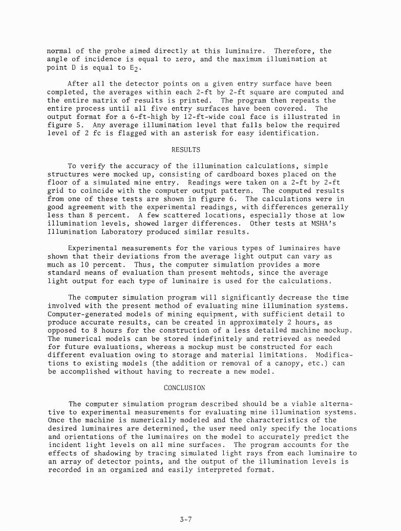
These d a t a a r e r ead by t h e program and s t o r e d f o r t h e c a l c u l a t i o n phase. The accuracy of t h e machine model can be v e r i f i e d by gene ra t ing a l i n e drawing o f t h e model on a v ideo d i s p l a y . A d e t a i l e d model of a cont inous miner, which was generated by t h e numerical modeling p roces s , i s i l l u s t r a t e d i n f i g u r e 2.

LUMINAI RE MEASUREMENTS
Experimental measurements must be made f o r a r e p r e s e n t a t i v e sample of each type of luminai re . These measurements determine t h e luminai res1 i s o i n t e n s i t y c h a r a c t e r i s t i c s i n o rde r t o d e f i n e an average luminaire f o r each type . The candlepower is determined a s a func t ion of t h e angular l i g h t d i s t r i b u t i o n of t h e luminai re . Th i s i s accomplished by p o s i t i o n i n g a photometer a t a f i x e d l o c a t i o n and vary ing t h e o r i e n t a t i o n of t h e lumi- n a i r e by t h e use of a goniometer. Some luminai res a r e equipped with a p r o t e c t i v e metal cage. The measurements a r e taken with t h e cage i n p l ace t o account f o r i t s e f f e c t s on t h e v a r i a t i o n i n l i g h t ou tpu t . Inc ident l i g h t measurements ( i n foo t - cand le s ) a r e made f o r every 10 degrees of o r i e n t a t i o n , r e s u l t i n g i n a s p h e r i c a l , l a t i t u d e - l o n g i t u d e arrangement. These d a t a a r e then reduced t o d e f i n e t h e candlepower of t h e luminaire f o r each angular l o c a t i o n by
where
E = i n c i d e n t l i g h t measurement ( f c ) d = d i s t a n c e from t h e photometer t o t h e luminaire ( f t )
These d a t a a r e then s t o r e d i n a luminai re l i b r a r y .
LUhIINAIRE LOCATION AND ORIENTATION
Once t h e luminai re types a r e modeled and s t o r e d i n t h e luminai re l i b r a r y , on ly t h e types of t h e luminai res d e s i r e d and t h e i r l o c a t i o n s and o r i e n t a t i o n s on t h e machine need t o be s p e c i f i e d . Figure 3 shows two machine l i g h t s (Type 1) and two head l igh t s (Type 2) mounted on t h e model of a cont inuous miner. The l o c a t i o n of a luminai re i s de f ined by x y z coo rd ina t e s , us ing t h e same coord ina t e system u t i l i z e d i n t h e machine modeling process . Thus, t h e l o c a t i o n of t h e c e n t e r of luminai re 1 i s def ined by t h e p o i n t (-2..5, 3.75, 15 .5 ) . Each luminaire i s assigned an aim and an a x i s v e c t o r which d e f i n e i t s o r i e n t a t i o n on t h e machine. S ince t h e a x i s v e c t o r of luminai re 1 i s d i r e c t e d toward t h e f a c e , p a r a l l e l t o t h e z a x i s i n t h e nega t ive d i r e c t i o n , it i s def ined by t h e coord ina tes ( 0 0 -1) . I t s aim v e c t o r i s d i r e c t e d toward t h e roof p a r a l l e l t o t h e p o s i t i v e y a x i s ; t h e r e f o r e , t h e aim v e c t o r i s def ined by t h e coo rd ina t e s ( 0 1, 0 ) The e n t i r e i npu t t h a t d e f i n e s t h e l o c a t i o n s and o r i e n t a t i o n s of t h e fou r luminai res i l l u s t r a t e d i n Figure 3 would c o n s i s t of t h e f 01 lowing :
LUM 1: Type = Type 1 Location = (-2.5, 3.75, 15.5) A i m = (0, 1, 0) Axis = (0, 0, -1)
LUM 2 : Type = Type 2 Location = (-2, 3.75, 7) A i m = (0, 0 , -1) Axis = (0 , 0, -1)

LUM 3 : Type = Type 1 Locat ion = (2 .5 , 3.75, 15.5) A i m = (0, 1, 0) Axis = (0, 0, -1)
LUM 4: Type = Type 2 Locat ion = (2, 3 .75, 7) A i m = (0, 0, -1) Axis = (0 , 0 , -1)
The l o c a t i o n o f t h e lumina i res can a l s o be de f ined by an a l t e r n a t e method. Th i s r e q u i r e s d i s p l a y i n g t h e machine model on t h e g raph ic s t e rmina l and us ing movable c r o s s h a i r s t o d e f i n e t h e l u m i n a i r e ' s p o s i t i o n on t h e model. However, t h e aim and t h e a x i s v e c t o r s must s t i l l be d e f i n e d .
P r i o r t o s t a r t i n g t h e i l l u m i n a t i o n c a l c u l a t i o n s , t h e program d e t e r - mines t h e v a l i d i t y of t h e l o c a t i o n s of t h e l umina i r e s . I t t e s t s whether any p o i n t on t h e a x i s of each lumina i re l i e s o u t s i d e t h e mine e n t r y o r i n s i d e any geometr ic shape comprising t h e machine model. I f e i t h e r c a s e occu r s , t h e lumina i re has been improperly l oca t ed , and t h e program i s te rmina ted .
I s should a l s o be noted t h a t h i g h - i n t e n s i t y d i s cha rge lamps and incandescent lamps can be t r e a t e d a s p o i n t e m i t t e r s owing t o t h e i r compact sources o f i l l u m i n a t i o n . However, t h e p o i n t source approximation f o r f l u o r e s c e n t l umina i r e s becomes i n v a l i d owing t o t h e l eng th o f t h e a r c t ube . Therefore , t h e program au toma t i ca l l y d i v i d e s t h e t ube i n t o sma l l e r segments and t r e a t s such segment a s a p o i n t e m i t t e r .
ILLUMINATION CALCULATIONS
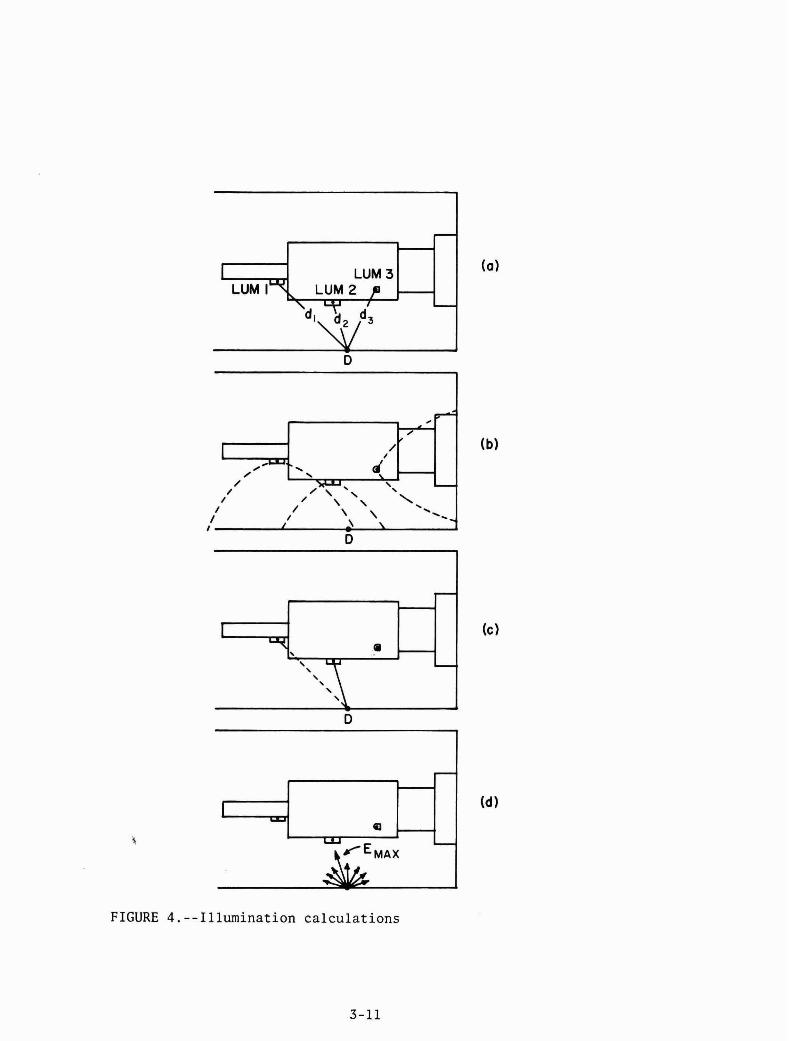
Once t h e lumina i r e s a r e pos i t i oned on t h e machine model and t h e dimensions o f t h e mine e n t r y a r e s p e c i f i e d , t h e i l l u m i n a t i o n c a l c u l a t i o n s beg in . A s an example, assume t h r e e lumina i res l oca t ed on a model of a cont inuous miner and a d e t e c t o r p o i n t D l oca t ed on t h e r i g h t r i b , a s i l l u s t r a t e d i n f i g u r e 4a . The c a l c u l a t i o n s proceed i n t h e fo l lowing manner :
(1) The d i s t a n c e d from lumina i re 1 t o t h e d e t e c t o r p o i n t D i s c a l c u l a t e d by
where x l , y l , z1 a r e t h e coo rd ina t e s t h a t d e f i n e t h e l o c a t i o n o f lumi- n a i r e 1 and x ~ , y ~ , Z D a r e t h e coo rd ina t e s t h a t d e f i n e t h e l o c a t i o n of t h e d e t e c t o r p o i n t . The d i s t a n c e s d2 and d3 a r e then determined i n a s i m i l a r f a s h i o n .
(2) S ince t h e l o c a t i o n of t h e lumina i res wi th r e s p e c t t o t h e d e t e c t o r p o i n t i s known, t h e candlepowers (I1, 12 , and I3 o f t h e lumi- n a i r e s a r e determined from t h e p r e s t o r e d angular d i s t r i b u t i o n d a t a .
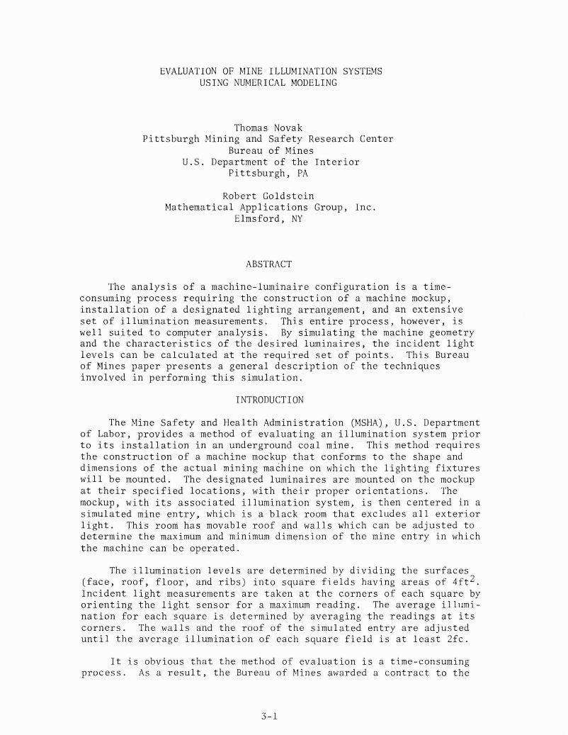
(3) The program tests whether the candlepower of any luminaire is equal to zero; if so, the illumination contribution E of the luminaire is assigned the value of zero. If the candlepower of the luminaire is greater than zero, the illumination contribution of the luminaire is calculated ignoring the cosine correction, by
Since luminaire 3 is a headlight which is oriented toward the face, the detector point D does not lie within the angular distribution pattern of the light as shown in figure 4b. Thus, the prestored angular distribu- tion tables would contain the value of zero for luminaire 3 in this particular situation. Therefore, E3 is assigned the value of zero. Since point D is within the angular distribution patterns of luminaires 1 and 2, the illumination contribution of each luminaire is calculated as follows:
I1 12 El = 7- and E2 = -7
d 7 d?
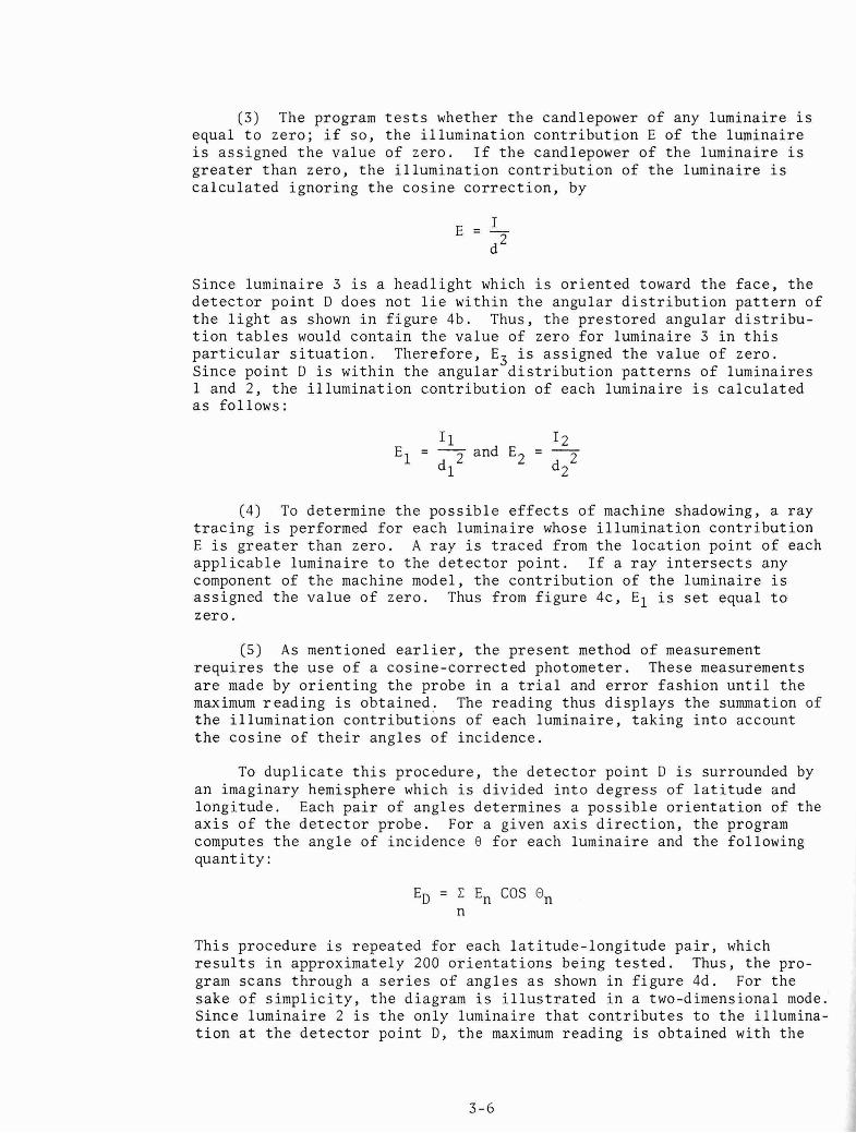
(4) To determine the possible effects of machine shadowing, a ray tracing is performed for each luminaire whose illumination contribution E is greater than zero. A ray is traced from the location point of each applicable luminaire to the detector point. If a ray intersects any component of the machine model, the contribution of the lumirlaire is assigned the value of zero. Thus from figure 4c, El is set equal to zero.
(5) As mentioned earlier, the present method of measurement requires the use of a cosine-corrected photometer. These measurements are made by orienting the probe in a trial and error fashion until the maximum reading is obtained. The reading thus displays the summation of the illumination contributions of each luminaire, taking into account the cosine of their angles of incidence.
To duplicate this procedure, the detector point D is surrounded by an imaginary hemisphere which is divided into degress of latitude and longitude. Each pair of angles determines a possible orientation of the axis of the detector probe. For a given axis direction, the program computes the angle of incidence 8 for each luminaire and the following quantity:
ED = C En COS On n
This procedure is repeated for each latitude-longitude pair, which results in approximately 200 orientations being tested. Thus, the pro- gram scans through a series of angles as shown in figure 4d. For the sake of simplicity, the diagram is illustrated in a two-dimensional mode. Since luminaire 2 is the only luminaire that contributes to the illumina- tion at the detector point D, the maximum reading is obtained with the
normal o f t h e probe aimed d i r e c t l y a t t h i s lumina i re . Therefore , t h e ang le o f inc idence i s equal t o zero , and t h e maximum i l l umina t ion a t p o i n t D i s equal t o E2.
A f t e r a l l t h e d e t e c t o r p o i n t s on a given e n t r y s u r f a c e have been completed, t h e averages w i th in each 2 - f t by 2 - f t square a r e computed and t h e e n t i r e ma t r ix of r e s u l t s i s p r i n t e d . The program then r e p e a t s t h e e n t i r e p roces s u n t i l a l l f i v e e n t r y s u r f a c e s have been covered. The ou tpu t format f o r a 6 - f t - h i g h by 12-f t -wide coa l f a c e i s i l l u s t r a t e d i n f i g u r e 5. Any average i l l u m i n a t i o n l e v e l t h a t f a l l s below t h e r equ i r ed l e v e l o f 2 f c i s f lagged wi th an a s t e r i s k f o r easy i d e n t i f i c a t i o n .
RESULTS
To v e r i f y t h e accuracy of t h e i l l u m i n a t i o n c a l c u l a t i o n s , s imple s t r u c t u r e s were mocked up, c o n s i s t i n g of cardboard boxes placed on t h e f l o o r of a s imula ted mine e n t r y . Readings were taken on a 2 - f t by 2 - f t g r i d t o co inc ide wi th t h e computer ou tput p a t t e r n . The computed r e s u l t s from one o f t h e s e t e s t s a r e shown i n f i g u r e 6 . The c a l c u l a t i o n s were i n good agreement wi th t h e experimental r ead ings , wi th d i f f e r e n c e s g e n e r a l l y l e s s t h a n 8 p e r c e n t . A few s c a t t e r e d l o c a t i o n s , e s p e c i a l l y t hose a t low i l l u m i n a t i o n l e v e l s , showed l a r g e r d i f f e r e n c e s . Other t e s t s a t MSHAts I l l u m i n a t i o n Laboratory produced s i m i l a r r e s u l t s .
Experimental measurements f o r t h e v a r i o u s t ypes of lumina i res have shown t h a t t h e i r d e v i a t i o n s from t h e average l i g h t ou tput can va ry a s much a s 10 p e r c e n t . Thus, t h e computer s imu la t i on provides a more s t anda rd means o f eva lua t ion than p r e s e n t mehtods, s i n c e t h e average l i g h t ou tpu t f o r each type of lumina i re i s used f o r t h e c a l c u l a t i o n s .
The computer s imu la t i on program w i l l s i g n i f i c a n t l y dec rease t h e t ime involved wi th t h e p r e s e n t method of eva lua t ing mine i l l u m i n a t i o n systems. Computer-generated models of mining equipment, wi th s u f f i c i e n t d e t a i l t o produce a c c u r a t e r e s u l t s , can be c r e a t e d i n approximately 2 hours , a s opposed t o 8 hours f o r t h e c o n s t r u c t i o n o f a l e s s d e t a i l e d machine mockup. The numerical models can be s t o r e d i n d e f i n i t e l y and r e t r i e v e d a s needed f o r f u t u r e e v a l u a t i o n s , whereas a mockup must be cons t ruc t ed f o r each d i f f e r e n t eva lua t ion owing t o s t o r a g e and m a t e r i a l l i m i t a t i o n s . Modifica- t i o n s t o e x i s t i n g models ( t h e a d d i t i o n o r removal of a canopy, e t c . ) can be accomplished without having t o r e c r e a t e a new model.
CONCLUSION
The computer s imu la t i on program desc r ibed should be a v i a b l e a l t e r n a - t i v e t o experimental measurements f o r eva lua t ing mine i l l u m i n a t i o n systems. Once t h e machine i s numer ica l ly modeled and t h e c h a r a c t e r i s t i c s of t h e d e s i r e d l umina i r e s a r e determined, t h e u s e r need only s p e c i f y t h e l o c a t i o n s and o r i e n t a t i o n s o f t h e lumina i res on t h e model t o a c c u r a t e l y p r e d i c t t h e i n c i d e n t l i g h t l e v e l s on a l l mine s u r f a c e s . The program accounts f o r t h e e f f e c t s o f shadowing by t r a c i n g s imulated l i g h t r ays from each lumina i re t o an a r r a y of d e t e c t o r p o i n t s , and t h e ou tput of t h e i l l u m i n a t i o n l e v e l s i s recorded i n an organized and e a s i l y i n t e r p r e t e d format .

FIGURE 1.--Simplified model of a continuous miner
h
X 0 > 0-
N
I 1 1 1 1 1 1 1 I
- - I f - - - - ------ - - 7 " - ----- - -- - J - - -
- N - - X - 0
m - - - -
I f M - X
- 0 - m - -
L--,-,,--
- - f" - w - X - 0
m - - 1 1 1 1 1 1 1 1 ~ ~ ~ ~ ~ ~ ~ ~ ,
-
- - - - - - - - - - - -
i
( r - - - - - -
.
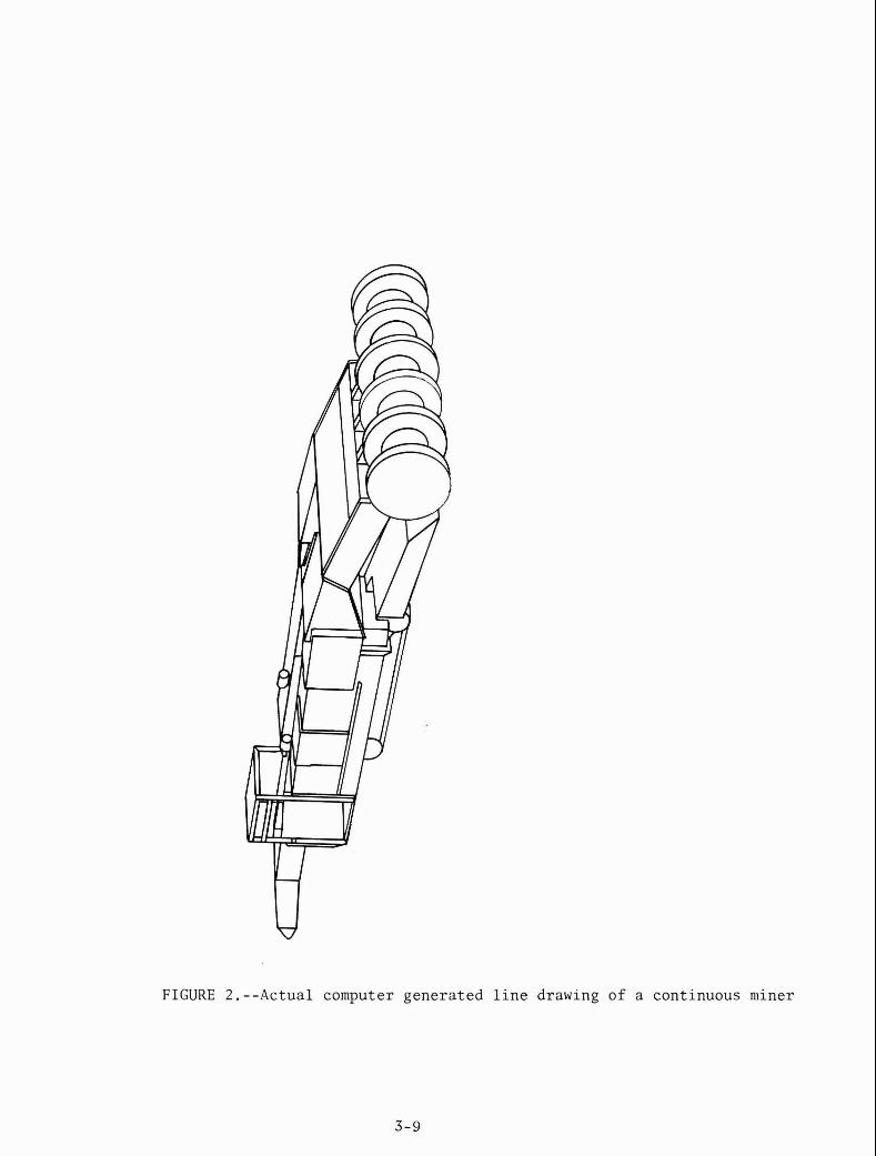
FIGURE 2 .
V
--Actual computer genera t e d l i n e drawing of a cont inuous niiner

FIGURE 3.--Location of luminaires on the machine mockup
LUM IT LUM 2 p \ '
FIGURE 4.--Illumination calculations

F A C E
0 2 4 6 8 10 12
1 .O 1.2 2.8 4.8 2.7 1.1 1.1
Avg . 1.2* 2.1 3.9 3.9 2.0 1.2*
1.2 1.4 3.0 5.0 2.9 1.4 1.3
Avg . 1.4* 2.3 4.2 4.2 2.2 1.4*
1.4 1.5 3.2 5.6 3.1 1.4 1.5
Avg . 1.3* 2.3 4.2 4.1 2.2 1.3*
1 .O 1.3 3.0 4.9 2.9 1.3 1.1
FIGURE 5. --Output format

0 1 2 3 4 5 6 7 8 9 10
Upper number is computed (fc) ; lower number is measured (fc)
FIGURE 6.--Calculated and measured results