Embed Size (px)
Citation preview
TRANSPORTATION RESEARCH RECORD 1223
Evaluation of Mechanical Expansion Anchors
JOHN P. DUSEL, JR.
Results of research conducted on mechanical expansion anchors for the purpose of revising an existing acceptance specification used by the California Department of Transportation are presented in this paper. The main objective of the research was to refine a portion of the standard specification dealing with mechanical expansion anchors, whose key requirement is to limit the amount of displacement that a mechanical expansion anchor can exhibit while being subjected to moderate sustained tensile loading. The scope of the work included (a) classifying mechanical expansion anchors from 14 manufacturers into five main categories and then further segregating them into types within each category, (b) conducting 465 ultimate tensile load tests on %-, 1/2-, and %-in.diameter zinc-electroplated mechanical expansion anchors to determine the point at which slip or yield occurs and their mean ultimate strength, (c) performing a total of 394 sustained tensile load creep tests at two different concrete strengths, (d) determining physical properties and chemical composition of suitable anchors, and (e) refining the standard specification and preparing a standard test method, California Test 681. The main alteration in the anchor specification included lowering the magnitudes of some sustained tension test loads for the required creep test and reducing the permitted displacement (0.050 to 0.035 in.) and time period (100 to 48 hrs) during which creep is monitored. The two anchor types found to be the best in each of their respective categoriesshell and stud-are (a) the shell nondrilling internal plug and (b) the stud wedge.
The California Department of Transportation (Caltrans) has an ongoing need to attach various fabricated products, including signs, inspection ladders, hand rail, glare screen posts, crash cushion bases, and various brackets, to surfaces of existing concrete structures. In many instances, both designers and maintenance personnel require a relatively inexpensive, yet reliable, anchorage device-the mechanical expansion anchorwhere more substantial or permanent anchoring methods are deemed unnecessary.
In recent years, many new types of mechanical expansion anchors have been developed. One of the newer types-the stud wedge-has become popular with many contractors. Reasons for its popularity are as follows:
• All required studs, nuts, and washers are furnished with the anchor;
• A multihole base plate can be used as a drill template, minimizing misaligned holes;
• The costs of drill bits and hole preparation are lower because the drill hole diameters required are smaller than those needed for shell-type anchors; and
• By minimizing drill hole diameters, the chance of encountering rebar is reduced.
California Department of Transportation, Transportation Laboratory, 5900 Folsom Boulevard, Sacramento, Calif. 95819.
A new improved style of shell anchor is a type having an internal tapered plug and is often referred to as "drop-in."
Until recent research was undertaken (1), only two older kinds of mechanical anchors-the flush-mounted shell external plug and stud external plug-had been tested and approved by Caltrans. In order for a mechanical expansion anchor to be approved for use in Caltrans contracts, requirements of the Caltrans Standard Specifications (Jan. 1988, Section 75-1.03) must be met.
Caltrans is the only known organization that considers the amount of creep of concrete anchorage devices during sustained tension loading to be the most meaningful measure of an anchor's ability to perform well under severe field conditions. Since 1973, Caltrans has included a creep evaluation as one of the key points in its specification. Before July 1984, acceptable anchors could not exhibit more than 0.050 in. of movement while subjected to a specified sustained tensile test load for a period of 100 hr. Unfortunately, no known manufacturer currently provides creep data, either short or long term, for mechanical expansion anchors. Almost all, however, offer ultimate shear and tension test data, which can be obtained relatively quickly and cheaply. Design engineers are concerned more with the "yield point" of an anchorage system, the amount of creep that may occur during long-term sustained loading, the performance of an anchor during dynamic loading, and the ability of an anchor to maintain a high tensile load after anchor movement has begun.
Before this research project (1) was completed, very little creep test data for mechanical expansion anchors were available (2), and there was no uniform test procedure established to determine creep. Some of the sustained tension test load values shown in earlier Caltrans standard specifications that were required to evaluate anchor creep were thought to be unrealistically high. Many of these test load values had been obtained by either interpolation or extrapolation from a few known sustained tension load values that had been determined for popular anchor sizes from a limited number of manufacturers.
Furthermore, there were no uniform requirements established for important physical properties of concrete test specimens in which mechanical expansion anchors were evaluated. Such important properties include compressive strength, modulus of elasticity, and cure time. Testing equipment and procedures used to collect the limited creep data also varied.
Because of the lack of demand for creep data by general users, manufacturers have been reluctant to spend the funds necessary to obtain comprehensive creep data for their mechanical anchors. Creep data are costly and time-consuming to develop and generally there has been little demand for such data by most users. Therefore, manufacturers have been
2
unwilling to provide creep data and unable to recommend realistic reductions in their published ultimate loads for conditions where either sustained tensile, dynamic, or impact loading govern .
A literature search was conducted and no published information concerning creep of mechanical expansion anchors was found. However, some interesting research papers dealing with both the static and dynamic behavior of mechanical expansion anchors were discovered (3-5).
The main objective of this research was to revise the existing Caltrans specification for mechanical expansion anchors as necessary, so that the sustained tensile test load values and the magnitude of displacement used to evaluate creep would be realistic numbers. To accomplish this objective, the scope of the research work included
• Classifying the variety of mechanical expansion anchors available;
• Conducting short-term direct tension tests and sustained tensile load (creep) tests;
• Determining physical properties, chemical composition, and corrosion resistance of suitable anchors;
• Developing a precise test method; and • Revising the standard specification.
DESCRIPTION OF TEST PROGRAM
Test Program Phases
To satisfy the project objective, the testing program was divided into five phases:
• Phase 1: Classifying various mechanical expansion anchors into distinct categories and determining anchor properties such as chemical composition, hardness, and corrosion resistance; performing chemical analysis on mechanical expansion anchors to determine percentage of key elements in the anchor metal.
• Phase 2: Conducting short-term direct tension tests to determine approximate system yield points and maximum pullout strengths for each anchor type.
• Phase 3: Conducting sustained tensile load tests to determine appropriate sustained load levels and typical magnitudes of creep for anchors in each major category and type; developing a comprehensive test method to evaluate creep of mechanical expansion anchors was done concurrently.
• Phase 4: Conducting additional sustained tensile load tests while varying the compressive strength of concrete in the test slabs to evaluate the effect of lower compressive strengths on the ability of anchors to resist sustained loads.
• Phase 5: Revising Section 75-1.03 of the July 1984 Caltrans Standard Specifications to reflect research results.
Classification of Mechanical Expansion Anchors
Through a literature search performed early in the project, a listing of 14 mechanical expansion anchor companies in the United States-Ackerman Johnson (formerly Illinois), CEB Corporation (formerly Chicago), Cunningham, Hilti, Liebig, Molly, Phillips, Ramset, Rawlplug, Star, U.S.E. Diamond, Universal, Wej-it, and Williams-was compiled.
TRANSPORTATION RESEARCH RECORD 1223
A preliminary evaluation of more than 80 different mechanical expansion anchors was made. Anchors were grouped into one of five categories shown in Table 1. Classifications were made based on appearance, dimensions, method of functioning, and unique physical characteristics.
Test Specimens
Mechanical Expansion Anchors
All mechanical expansion anchors used for testing had a standard zinc-electroplated coating. Anchor lengths tested were generally the shortest available .
Phase 1: Samples of V2- and %-in.-diameter mechanical expansion anchors from six major manufacturers were chosen for evaluation to determine hardness of anchor parts, chemical composition, and potential for corrosion in a salt spray environment. These manufacturers were Hilti, Molly, Phillips, Ramset, Rawlplug , and Star.
Phase 2: A total of 465 mechanical expansion anchors from 14 manufacturers were tested for ultimate tensile strength. Anchor sizes evaluated were V4-, 112-, and %-in.-diameter in the shell and stud categories and additional sizes in the miscellaneous category.
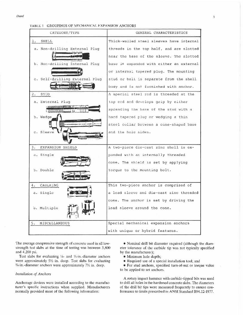
Phase 3: A total of 322 mechanical expansion anchors were tested for periods up to 100 hr to determine creep behavior under a sustained tensile load. Sizes and types of anchors tested are shown in Table 2. Tests were performed in unreinforced concrete slabs having nominal compressive strengths of 5,000 psi. Anchor categories evaluated included the shell and stud. Sizes tested included the Y4-, V2-, and %-in.-diameter anchors. Manufacturers of anchors evaluated included Hilti, Molly, Phillips, Ramset, Rawlplug, and Star.
Phase 4: A total of 72 mechanical exp;msion anchors, whic.h appeared to be acceptable from the results of Phase 3 testing, were evaluated in concrete of a lower compressive strength (4,000 psi) to determine its effects on creep. Anchor sizes tested (shown in Table 3) include Y4-, V2-, and %-in. diameters. Anchors from the same manufacturers evaluated in Phase 3 were used here .
Concrete Slabs
Ready-mix concrete was used to construct test slabs, which were unreinforced. The aggregate used conformed to the 1-in . maximum grading in Caltrans Standard Specifications (CSS) (Jan. 1988, Section 90-3.04). For testing in Phases 2 and 3, a Class A concrete (CSS, Jan. 1988), containing 564 pounds of Type II modified portland cement per cubic yard (six-sack mix) was used. The average slump attained was 3 in. The average compressive strength of each test slab was determined by averaging compressive strengths of three 6- x 12-in. concrete cylinders made and cured with the slabs. The average compressive strength of concrete used in Phase 2 test slabs was 4,000 psi. The average compressive strength of concrete in all Phase 3 test slabs at the time of testing was between 4,800 and 5,200 psi. For Phase 4 testing, a lower strength Class B concrete (CSS, Jan. 1988) was used, which contained 470 pounds of Type II modified portland cement per cubic yard (five-sack mix). The average slump attained was 4 in.
Dusel 3
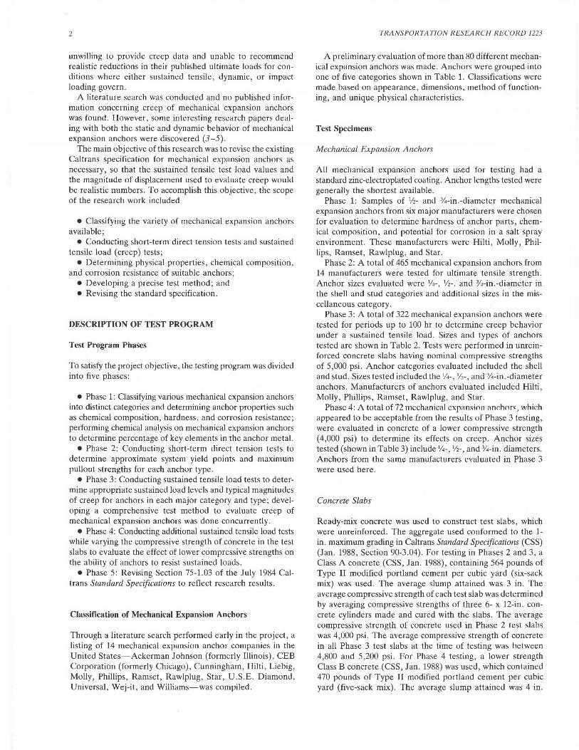
TABLE 1 GROUPINGS OF MECHANICAL EXPANSION ANCHORS
CATEGORY/TYPE GENERAL CHARACTERISTICS
1. SHELL Thick-walled steel sleeves have internal
a. Non-drilling External Plug threads in the top half, and are slotted
a ==- near the base of the sleeve. The slotted
b. Non-drilling Internal Plug base is expanded with either an external
I ~ internal tapered plug. The mounting or '
c. Self-drilling External Plug stud or bolt is separate from the shell
E3·f· ~~ body and is not furnished with anchor.
2. STUD A special steel rod is threaded at the
a. External Plug top end and develops grip by either
;~\i\\tlli\~~·~'5fff= spreading the base of the stud with a
b. Wedg~ hard tapered plug or wedging a thin
steel collar between a cone-shaped base «~----1. ;'I-· ;j c.
Sleeve I (4=• 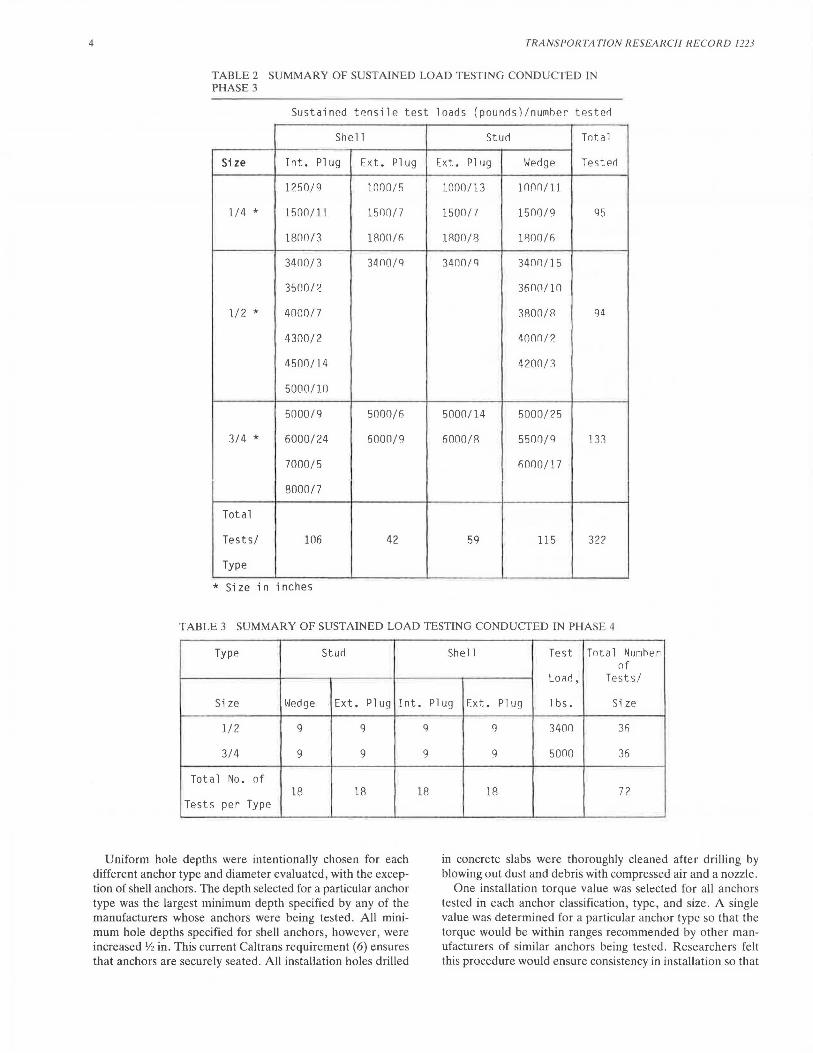
4 TRANSPORTATION RESEARCH RECORD 1223
TABLE 2 SUMMARY OF SUSTAINED LOAD TESTING CONDUCTED IN PHASE 3
Sustained tensile test loads (pounrls)/nurnher testerl
Shell Sturl Total
Size Int. Plug Ext. Plug Ext. Plug Werlge Test erl
1250/9 1000/ 5 l.000/13 1000/l l
1/4 * 1500/11 1500/7 1500/7 1500/9 95
180() / 3 1800/ f; 1800/8 1800/6
3400/3 3400 / 9 34()0/9 3400 / 15
3500/2 360(1/10
l/2 * 4000/7 3800/R 94
4300/2 4000/2
4500/14 4200/3
5000/10
5000/9 5000/1:\ 5000/1.4 5000/2 5
3/4 * 6000/24 6000/9 6000/8 5500/9 133
7000/5 6000/17
8000/7
Total
Tests/ 106 42 59 115 32l'
Type
* Size in inches
TABLE 3 SUMMARY OF SUSTAINED LOAD TESTING CONDUCTED IN PHASE 4
Type Sturl
Size Wedge Ext. Pl UCJ Int.
1/2 9 q
3/4 9 9
Total No. of 18 18
Tests per Type
Uniform hole depths were intentionally chosen for each different anchor type and diameter evaluated, with the exception of shell anchors. The depth selected for a particular anchor type was the largest minimum depth specified by any of the manufacturers whose anchors were being tested. All minimum hole depths specified for shell anchors, however, were increased Y2 in. This current Caltrans requirement (6) ensures that anchors are securely seated. All installation holes drilled
9
9
18
She 11 Test Total N.umher of
Loarl, Tests/
Plug Ext. Plug lbs. Size
9 3400 3fi
9 5000 36
18 72
in concrete slabs were thoroughly cleaned after drilling by blowing out dust and debris with compressed air and a nozzle.
One installation torque value was selected for all anchors tested in each anchor classification, type, and size. A single value was determined for a particular anchor type so that the torque would be within ranges recommended by other manufacturers of similar anchors being tested. Researchers felt this procedure would ensure consistency in installation so that
Dusel
results could be compared directly. Values of other parameters, including hole depth, tip diameter of drill bits, setting procedures used, and installation torque versus turn-of-nut values, were measured and recorded for each test.
Test Equipment and Procedures
All anchors evaluated in this research were tested under conditions similar to those encountered in Caltrans' contracts . Installation and testing were performed according to requirements and procedures in California Test 681 (7), a standard test method developed in this research project for evaluating creep of mechanical expansion anchors.
NUT 8 WASHER
5
Short-Term Direct Tension Pullout Tests (Phase 2)
A minimum of three replicate tests was performed on anchors from each manufacturer tested. Minimum edge distance for all anchors tested in Phase 2 and subsequent phases was 5 hole diameters, and minimum spacing between all anchors was 10 hole diameters. If dispersion of pullout data was large and the results from any one test deviated more than 15 percent from the mean , then two additional pullout tests were performed.
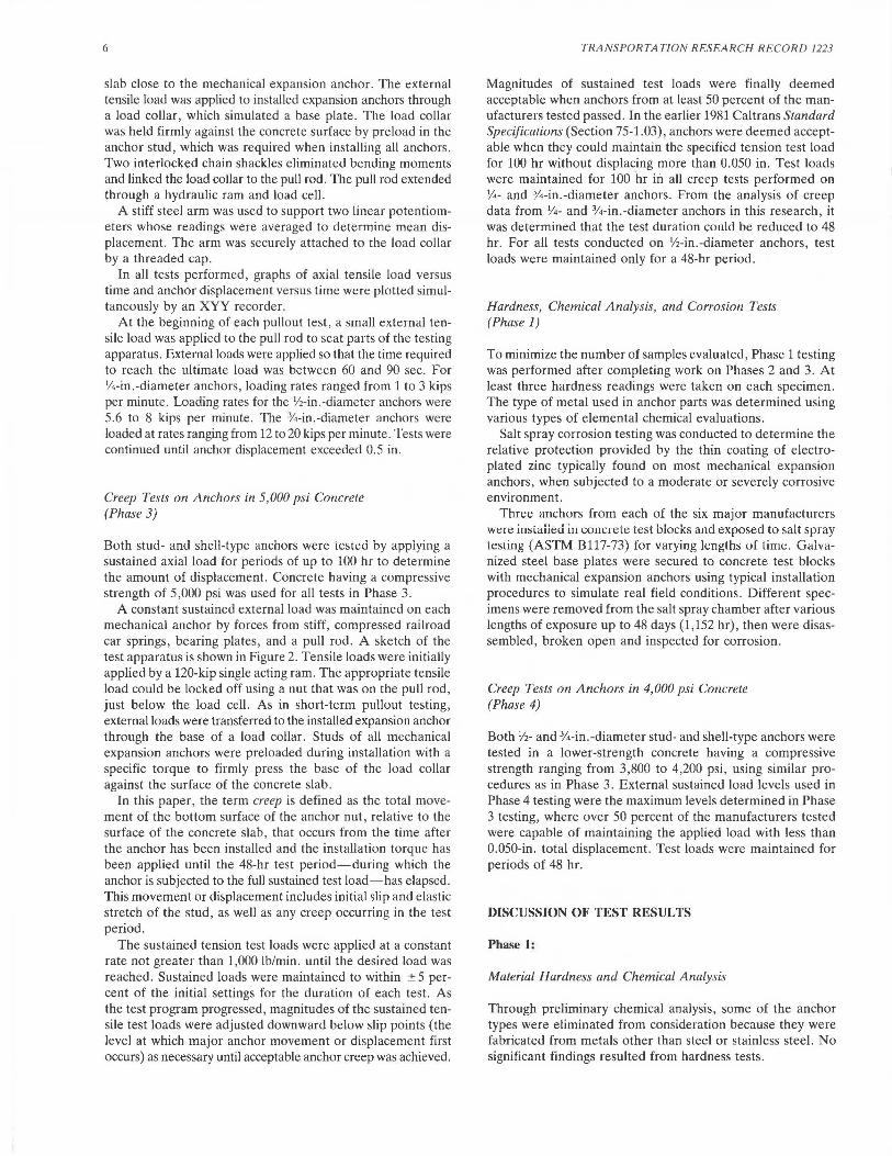
A special movable loading frame, shown in Figure 1, supported the hydraulic ram and load cell. A set of interchangeable base rings with different diameters was made and a ring was chosen that would avoid any reaction on the concrete
PULL BAR
LOAD CELL
HYDRAULIC JACK
811 cjl x t" THICK STEEL CYLINDER
// 10" Q> STEEL PLATE SWIVEL JOINT ASSEMBLY
REMOVABLE BASE RING
111
THICK BASE PLATE
MECHANICAL EXPANSION ANCHOR
-<.O N
I I \ I\ ,, ,,
b . ELEVATION VIEW
,, ,, , .... '~:::::::= =:::::.
----- 26"-----...
a. PLAN VIEW
I
I
~
I
FIGURE 1 Portable testing apparatus wr conducting short-term ultimate tension load tests.
6
slab close to the mechanical expansion anchor. The external tensile load was applied to installed expansion anchors through a load collar, which simulated a base plate. The load collar was held firmly against the concrete surface by preload in the anchor stud, which was required when installing all anchors. Two interlocked chain shackles eliminated bending moments and linked the load collar to the pull rod. The pull rod extended through a hydraulic ram and load cell.
A stiff steel arm was used to support two linear potentiometers whose readings were averaged to determine mean displacement. The arm was securely attached to the load collar by a threaded cap.
In all tests performed, graphs of axial tensile load versus time and anchor displacement versus time were plotted simultaneously by an XYY recorder.
At the beginning of each pullout test, a small external tensile load was applied to the pull rod to seat parts of the testing apparatus. External loads were applied so that the time required to reach the ultimate load was between 60 and 90 sec. For V4-in.-diameter anchors, loading rates ranged from 1 to 3 kips per minute. Loading rates for the V2-in.-diameter anchors were 5.6 to 8 kips per minute. The %-in.-diameter anchors were loaded at rates ranging from 12 to 20 kips per minute. Tests were continued until anchor displacement exceeded 0.5 in.
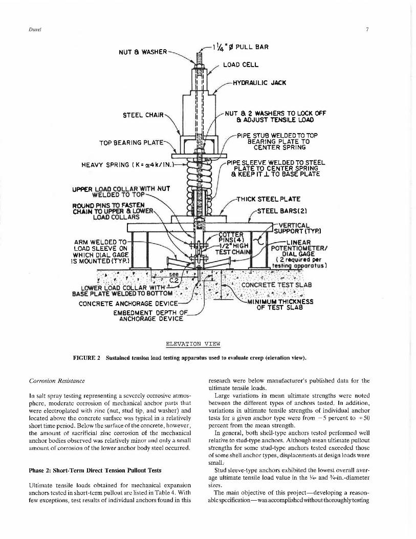
Creep Tests on Anchors in 5,000 psi Concrete (Phase 3)
Both stud- and shell-type anchors were tested by applying a sustained axial load for periods of up to 100 hr to determine the amount of displacement. Concrete having a compressive strength of 5,000 psi was used for all tests in Phase 3.
A constant sustained external load was maintained on each mechanical anchor by forces from stiff, compressed railroad car springs, bearing plates, and a pull rod. A sketch of the test apparatus is shown in Figure 2. Tensile loads were initially applied by a 120-kip single acting ram. The appropriate tensile load could be locked off using a nut that was on the pull rod, just below the load cell. As in short-term pullout testing, external loads were transferred to the installed expansion anchor through the base of a load collar. Studs of all mechanical expansion anchors were preloaded during installation with a specific torque to firmly press the base of the load collar against the surface of the concrete slab.
In this paper, the term creep is defined as the total movement of the bottom surface of the anchor nut, relative to the surface of the concrete slab, that occurs from the time after the anchor has been installed and the installation torque has been applied until the 48-hr test period-during which the anchor is subjected to the full sustained test load-has elapsed. This movement or displacement includes initial slip and elastic stretch of the stud, as well as any creep occurring in the test period.
The sustained tension test loads were applied at a constant rate not greater than 1,000 lb/min. until the desired load was reached. Sustained loads were maintained to within :!:: 5 percent of the initial settings for the duration of each test. As the test program progressed, magnitudes of the sustained tensile test loads were adjusted downward below slip points (the level at which major anchor movement or displacement first occurs) as necessary until acceptable anchor creep was achieved.
TRANSPORTATION RESEARCH RECORD 1223
Magnitudes of sustained test loads were finally deemed acceptable when anchors from at least 50 percent of the manufacturers tested passed. In the earlier 1981 Caltrans Standard Specifications (Section 75-1.03), anchors were deemed acceptable when they could maintain the specified tension test load for 100 hr without displacing more than 0.050 in. Test loads were maintained for 100 hr in all creep tests performed on %- and %-in.-diameter anchors. From the analysis of creep data from %- and %-in.-diameter anchors in this research, it was determined that the test duration could be reduced to 48 hr. For all tests conducted on V2-in.-diameter anchors, test loads were maintained only for a 48-hr period.
Hardness, Chemical Analysis, and Corrosion Tests (Phase 1)
To minimize the number of samples evaluated, Phase 1 testing was performed after completing work on Phases 2 and 3. At least three hardness readings were taken on each specimen. The type of metal used in anchor parts was determined using various types of elemental chemical evaluations.
Salt spray corrosion testing was conducted to determine the relative protection provided by the thin coating of electroplated zinc typically found on most mechanical expansion anchors, when subjected to a moderate or severely corrosive environment.
Three anchors from each of the six major manufacturers were iusiailed in concrete test blocks and exposed to salt spray testing (ASTM B117-73) for varying lengths of time. Galvanized steel base plates were secured to concrete test blocks with mechanical expansion anchors using typical installation procedures to simulate real field conditions. Different specimens were removed from the salt spray chamber after various lengths of exposure up to 48 days (1,152 hr), then were disassembled, broken open and inspected for corrosion.
Creep Tests on Anchors in 4,000 psi Concrete (Phase 4)
Both V2- and %-in.-diameter stud- and shell-type anchors were tested in a lower-strength concrete having a compressive strength ranging from 3,800 to 4,200 psi, using similar procedures as in Phase 3. External sustained load levels used in Phase 4 testing were the maximum levels determined in Phase 3 testing, where over 50 percent of the manufacturers tested were capable of maintaining the applied load with less than 0.050-in. total displacement. Test loads were maintained for periods of 48 hr.
DISCUSSION OF TEST RES UL TS
Phase 1:
Material Hardness and Chemical Analysis
Through preliminary chemical analysis, some of the anchor types were eliminated from consideration because they were fabricated from metals other than steel or stainless steel. No significant findings resulted from hardness tests.
Dusel
NUT a WASHER
UPPER LOAD COLLAR WITH NUT WELDED TO TOP
ROUND PINS TO FASTEN CHAIN TO UPPER a LCMER
LOAD COLLARS
ARM WELDED TO_.._..___ LOAD SLEEVE ON WHICH DIAL GAGE
IS MOUNTED (TYP.)
EMBEDMENT DEPTH OF ANCHORAGE 0£VICE
1 l,14 II !lJ PULL BAR
LOAD CELL
HYDRAULIC JACK
NUT a 2 WASHERS TO LOCK OfF a ADJUST TENSILE LOAD
PIPE STUB WELDEDTOTOP BEARING PLATE TO
CENTER SPRING
THICK STEELPLATE
STEEL BARS ( 2 l
7
ELEVATION VIEW
FIGURE 2 Sustained tension load testing apparatus used to evaluate creep (elevation view) .
Corrosion Resistance
In salt spray testing representing a severely corrosive atmosphere, moderate corrosion of mechanical anchor parts that were electroplated with zinc (nut, stud tip, and washer) and located above the concrete surface was typical in a relatively short time period. Below the surface of the concrete, however, the amount of sacrificial zinc corrosion of the mechanical anchor bodies observed was relatively minor and only a small amount of corrosion of the lower anchor body steel occurred.
Phase 2: Short-Term Direct Tension Pullout Tests
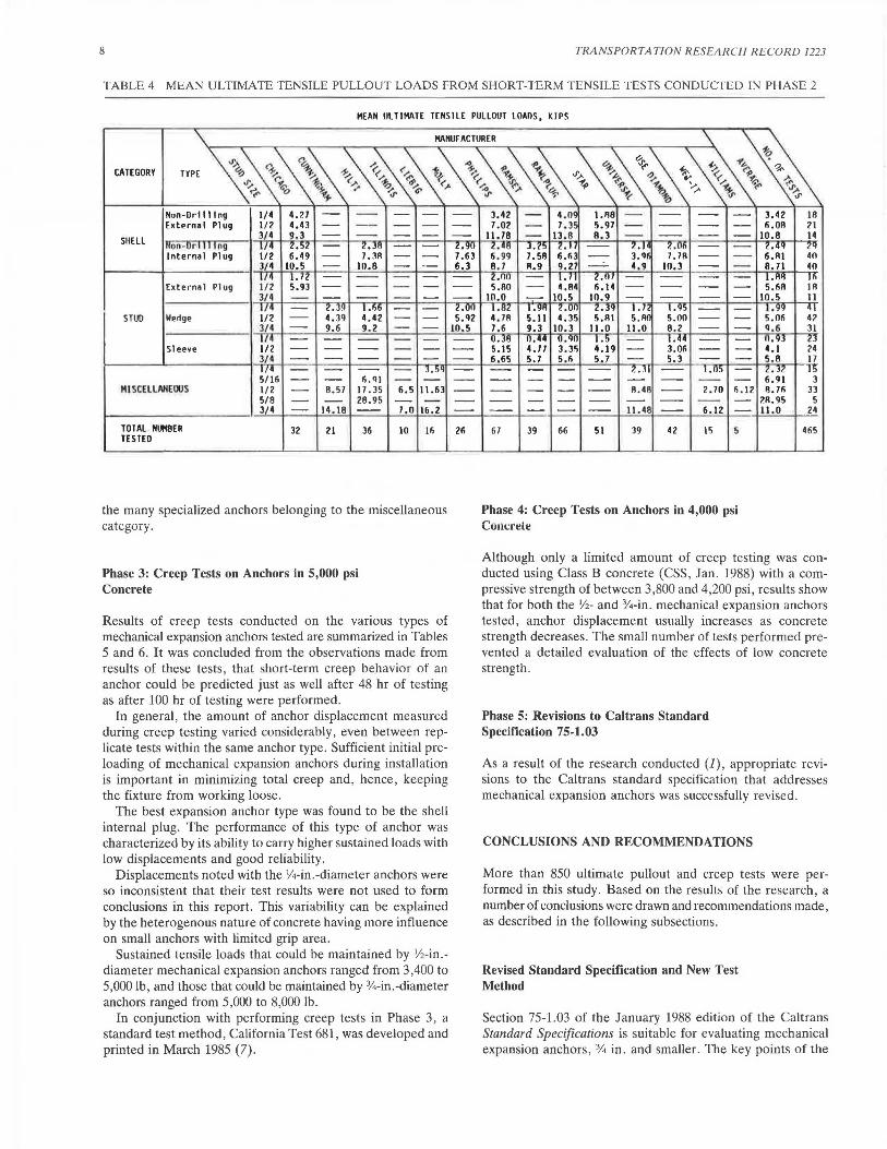
Ultimate tensile loads obtained for mechanical expansion anchors tested in short-term pullout are listed in Table 4. With few exceptions, test results of individual anchors found in this
research were below manufacturer's published data for the ultimate tensile loads.
Large variations in mean ultimate strengths were noted between the different types of anchors tested. In addition, variations in ultimate tensile strengths of individual anchor tests for a given anchor type were from - 5 percent to + 50 percent from the mean strength.
In general, both shell-type anchors tested performed well relative to stud-type anchors. Although mean ultimate pullout strengths for some stud-type anchors tested exceeded those of some shell anchor types, displacements at design loads were small ..
Stud sleeve-type anchors exhibited the lowest overall average ultimate tensile load value in the %- and %-in.-diameter sizes.
The main objective of this project-developing a reasonable specification-was accomplished without thoroughly testing
8 TRANSPORTATION RESEARCH RECORD 1223
TABLE 4 MEAN ULTIMATE TENSILE PULLOUT LOADS FROM SHORT-TERM TENSILE TESTS CONDUCTED IN PHASE 2
MEAN ULTIMATE TENSILE PULLOUT LOAOS, KIPS
' """""'" ' ~ CATEGORY ... ·~
~ ~ ~ _,. t.~ ( •. <"..., ~ 1: .,.1' ~ ~.,,,. ~~ ~ 1- 0 ~.,.,, ~G' ~,.. ~ ~~,A",/' ~
Non-Or1111 ng 1/4 4. ?.1 - - - -Extern• I Pl ug 1/2 4.43 - - - -
SUELL 3/ 4 9, 3 - - - -Ron-Ori 111 ng 1/ 4 z.~z 2.J8 Internal Plug 1/2 6 . 49 - 7.JR - -
3/4 10.5 - 10.8 - -1/4 I. 72 - -- - -
External Plug 1/2 5.93 - -- - -3/4 - - - - -1/4 2.39 1. 66 -
STUD Wedge 1/2 - 4. 39 4.42 - -3/4 - 9. 6 9.2 - -1/4 - - - - -
Sleeve 1/2 - - - - -3/4 - - - - -1/4 - 3.5g 5/ 16 - - Ii.QI - -
HI SCELLMEOOS 1/2 - 8.57 11.35 6.5 11.63 5/8 - - 28.95 - -3/4 - 14.18 -- 7.0 16.2
TOTAL . N~DER 32 21 36 10 16 TESTED
the many specialized anchors belonging to the miscellaneous category.
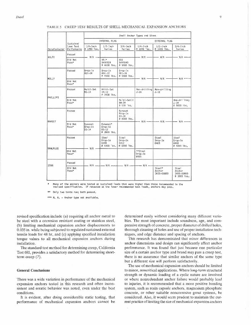
Phase 3: Creep Tests on Anchors in 5,000 psi Concrete
Results of creep tests conducted on the various types of mechanical expansion anchors tested are summarized in Tables 5 and 6. It was concluded from the observations made from results of these tests, that short-term creep behavior of an anchor could be predicted just as well after 48 hr of testing as after 100 hr of testing were performed.
In general, the amount of anchor displacement measured during creep testing varied considerably, even between replicate tests within the same anchor type. Sufficient initial preloading of mechanical expansion anchors during installation is important in minimizing total creep and, hence, keeping the fixture from working loose.
The best expansion anchor type was found to be the shell internal plug. The performance of this type of anchor was characterized by its ability to carry higher sustained loads with low displacements and good reliability.
Displacements noted with the Y4-in.-diameter anchors were so inconsistent that their test results were not used to form conclusions in this report. This variability can be explained by the heterogenous nature of concrete having more influence on small anchors with limited grip area.
Sustained tensile loads that could be maintained by Y2-in.diameter mechanical expansion anchors ranged from 3 ,400 to 5,000 lb, and those that could be maintained by %-in.-diameter anchors ranged from 5,000 to 8,000 lb.
In conjunction with performing creep tests in Phase 3, a standard test method, California Test 681, was developed and printed in March 1985 (7).
---z.~11
7.6J 6.3 ---2.00 5.'12
10.5 -------26
3. 42 - 4 .o< 1.1!8 - -- - -7 .02 - 7 .35 5.97 - -- - -
11.78 - IJ. 8 8 , J - -- - -7. .48 J.{~ 2." 7. .1 ~ 7..11~
6. 99 7. 58 6 . fi J - J. q~ 7. 7R - -8. 7 R.9 9. 27 - 4,9 10,3 - -2.no - I. II 2. nr - -- - -5.80 - 4.84 fi.14 - -- - -
10.0 - 10.5 10.9 - -- - -1.82 ··~" ?. .on 2. 3'1 I. Tl l.'15 -- -4. 7R 5.11 4.35 5.RI 5.RC 5. 00 - -7.6 9.J 10.3 11.0 11.0 8. 2 - -0. J 8 11.44 U.'flJ 1.5 - 1.44 - -5.15 4.77 3. 3S 4.19 - 3.06 - -6,65 5.7 5.6 5.7 - 5. 3 - -
- - ?. • JI l.n~
- - - -- - -- -- -- - - -- R.4R - 2. 70 fi.12 -- - - - - -- -- --- - - -- 11.48 -- 6.12 -67 39 66 51 39 42 15 s
Phase 4: Creep Tests on Anchors in 4,000 psi Concrete
3. 42 Ill Ii.Oii 21
10.8 14 Z.4'f 2'f 6.RI 40 8. 71 40 I.RI! 16 5.611 IA
10 . 5 11 1. 99 41 5.06 42 Q.6 31 0 . 93 23 4.1 24 5 . 8 17 2 . JZ IS 6.91 3 fl. 76 33
?.R.95 5 11.0 24
465
Although only a limited amount of creep testing was conducted using Class B concrete (CSS, Jan . 1988) with a compressive strength of between 3,800 and 4,200 psi, results show that for both the V2- and %-in. mechanical expansion anchors tested, anchor displacement usually increases as concrete strength decreases. The small number of tests performed prevented a detailed evaluation of the effects of low concrete strength.
Phase 5: Revisions to Caltrans Standard Specification 75-1.03
As a result of the research conducted (J), appropriate revisions to the Caltrans standard specification that addresses mechanical expansion anchors was successfully revised.
CONCLUSIONS AND RECOMMENDATIONS
More than 850 ultimate pullout and creep tests were performed in this study. Based on the results of the research, a number of conclusions were drawn and recommendations made, as described in the following subsections.
Revised Standard Specification and New Test Method
Section 75-1.03 of the January 1988 edition of the Caltrans Standard Specifications is suitable for evaluating mechanical expansion anchors,% in. and smaller. The key points of the
Dusel 9
TABLE 5 CREEP TEST RESULTS OF SHELL MECHANICAL EXPANSION ANCHORS
Shel 1 Anchor Types and Sizes
INTERNAL PLllG EXTERNAL PLUG Sustained Load Test 1/4-lnch 1/2-lnch 314- [nch 1/4-lnch 1/2-lnch 314-lnch
Manufacturer Performance @ 1250 lbs. Varies Varies ~ 1000 lbs. @ 3400 lbs. Varies
Passed H!LTI N/A NIA- -NIA- >--NIA --
Did Not HO[* HO[ Pass• 5490024 5490040
@ 4000 lbs. @ 5000 l bs.
Passed Drop- ln Drop- r n Drop- [ n MDl-14 HD!-12 HD!-34
@ 4500 lbs. @ 5000 lbs . MOLLY NIA--N/A->--NIA --
Did Not Pass*
Passed Multi -Set Mil ti-Set Non-dri 11 i ng Non-dri 11 i ng MS-14 RM-12 J-14 J-12
@ 3400 1 bs. PHILLIPS
Did Not Multi-Seti! Non-drilling Pass• RH-34 J-34
@ 500 lbs. @ soon lbs.
Passed Oynaset Orop- [n OS-34 @ 6000 lbs.
RAMS ET NIA NIA->-NIA--01 d Not Dyna set OynasP.t* Pass• Drop- r n Drop-ln
DS-14 DS-12 @ 35DO lbs.
Passed Steel Steel Steel Steel Orop-rn Drop-ln Drop-In Drop-ln 6308 6312 6465 6468 @ 4DOD lbs. @ 6000 lbs. @ 60DO lbs .
RAWL PLUG N/A Did Not **Steel Pass* Drop- In
6460
Passed STAR NIA - >-NIA- - N/A NI A
Did Not Steel* Stee l Pass• Anchor Anchor
3435-00800 3455-00800 @ 3000 lbs .
Many of the anchors were tested at sustained loads that were higher than those rec011111ended in the revised spec1f1cat1on .. If retested at the lower reconvnended test loads, anchors may pass.
Only two tests run; both passed.
••• N. A. - Anchor type not available.
revised specification include (a) requiring all anchor metal to be steel with a corrosion resistant coating or stainless steel, (b) limiting mechanical expansion anchor displacements to 0.035 in. while being subjected to regulated sustained external tensile loads for 48 hr, and (c) applying specified installation torque values to all mechanical expansion anchors during installation.
The standard test method for determining creep, California Test 681, provides a satisfactory method for determining shortterm creep (7).
General Conclusions
There was a wide variation in performance of the mechanical expansion anchors tested in this research and often inconsistent and erratic behavior was noted, even under the best conditions.
It is evident, after doing considerable static testing, that performance of mechanical expansion anchors cannot be
determined easily without considering many different variables. The most important include soundness, age, and compressive strength of concrete, proper diameter of drilled holes, thorough cleaning of holes and use of proper installation techniques, and edge distance and spacing of anchors.
This research has demonstrated that minor differences in anchor dimensions and design can significantly affect anchor performance. It was found that just because one particular size of a certain anchor type and brand may pass a creep test, there is no assurance that similar anchors of the same type but a different size will perform satisfactorily.
The use of mechanical expansion anchors should be limited to minor, noncritical applications. Where long-term structural strength or dynamic loading of a cyclic nature are involved or where nonredundant anchor failure would probably lead to injuries, it is recommended that a more positive bonding system, such as resin capsule anchors, magnesium phosphate concrete, or other suitable noncorrosive grout systems, be considered. Also, it would seem prudent to maintain the current practice of limiting the size of mechanical expansion anchors
10 TRANSPORTATION RESEARCH RECORD 1223
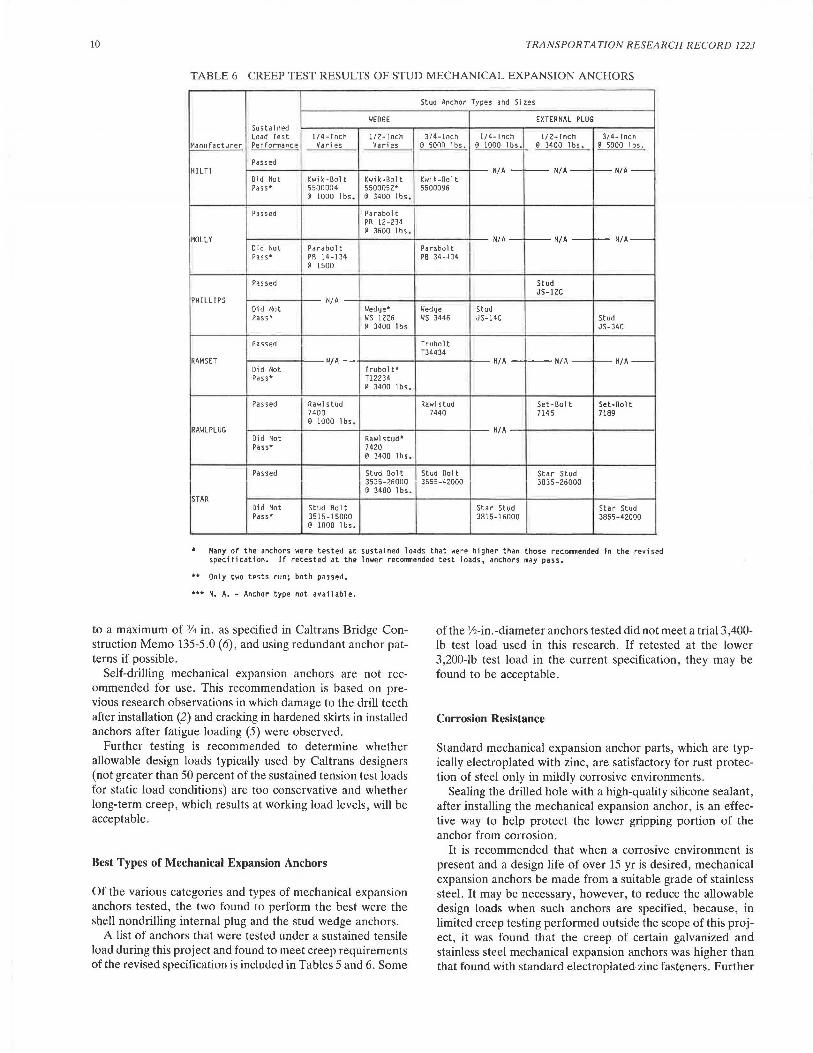
TABLE 6 CREEP TEST RESULTS OF STUD MECHANICAL EXPANSION ANCHORS
Stud Anchor Types and Sizes
WEOGE EXTERNAL PLUG Sustained Load Test 1/4-lnch 1/2-lnch 3/4-lnch 1/4-lnch 1/2-lnch 3/4-lnch
Manufacturer Performance Vari es Vari es @ 5onn lbs. @ 1000 lbs. @ 3400 lbs. @ 5000 lbs.
Passed HILT! N/A - i---- N/A N/A-
Did Not Kwi k-Bol t Kwik-Bolt Kwi k-Bol t Pass* 5500004 5500052* 5500096
@ lOOO lbs. @ 3400 lbs.
Passed Parabol t PR 12-234 @ 3600 lbs.
MOLLY
I N/A N/A--NIA-
Did Not Parabolt Parabolt Pass* PR 14-134 PB 34-~J4
@ 1500
Passed Stud JS-12C
PHILLIPS N/A Did Not Wedge"" Wedge Stud Pass* ws 1226 ws 3446 JS-14C Stud
@ 3400 l bs JS-34C
Passed Trubolt T34434
RAM SET ~/A N/A N/A N/A--Did Not Trubolt* Pass* Tl2234
@ 3400 lbs.
Passed Rawl stud Rawl stud Set-Bolt Set-Bolt 7400 7440 7145 71B9 @ 1000 lbs.
RAWL PLUG N/A Did Not Rawl stud* Pass• 7420
@ 3400 1 bs.
Passed Stud Bolt Stud Bolt Star Stud 3535-26000 3555-42000 3835-26000 @ 3400 1 bs.
STAR Did Not Stud Rolt Star Stud Star Stud Pass• 3515-15000 3815-16000 3855-42000
@ 1000 lbs.
Many of the anchors were tested at sustained loads that were higher than those recormnended in the revised speci Fi cation. If retested at the lower reco1T1J1ended test loads, anchors may pass.
Only two te:;t:; run: both pil:ned.
••• N. A. - Anchor type not available.
to a maximum of % in. as specified in Caltrans Bridge Construction Memo 135-5.0 (6), and using redundant anchor patterns if possible.
Self-drilling mechanical expansion anchors are not recommended for use. This recommendation is based on previous research observations in which damage to the drill teeth after installation (2) and cracking in hardened skirts in installed anchors after fatigue loading (5) were observed.
Further testing is recommended to determine whether allowable design loads typically used by Caltrans designers (not greater than 50 percent of the sustained tension test loads for static load conditions) are too conservative and whether long-term creep, which results at working load levels, will be acceptable.
Best Types of Mechanical Expansion Anchors
Of the various categories and types of mechanical expansion anchors tested, the two found to perform the best were the shell nondrilling internal plug and the stud wedge anchors.
A list of anchors that were tested under a sustained tensile load during this project and found to meet creep requirements of the revised specification is included in Tables 5 and 6. Some
of the V2-in.-diameter anchors tested did not meet a trial 3,400-lb test load used in this research. If retested at the lower 3,200-lb test load in the current specification, they may be found to be acceptable.
Corrosion Resistance
Standard mechanical expansion anchor parts, which are typically electroplated with zinc, are satisfactory for rust protection of steel only in mildly corrosive environments.
Sealing the drilled hole with a high-quality silicone sealant, after installing the mechanical expansion anchor, is an effective way to help protect the lower gripping portion of the anchor from corrosion.
It is recommended that when a corrosive environment is present and a design life of over 15 yr is desired, mechanical expansion anchors be made from a suitable grade of stainless steel. It may be necessary, however, to reduce the allowable design loads when such anchors are specified, because, in limited creep testing performed outside the scope of this project, it was found that the creep of certain galvanized and stainless steel mechanical expansion anchors was higher than that found with standard electroplated zinc fasteners. Further
Dusel
work with special corrosion resistant anchor finishes and types was outside the scope of this project. It is recommended that special corrosion resistant anchors be tested before use and design loads adjusted accordingly.
Recommended Installation Techniques
It was concluded that the following installation rules are important:
• Use rotary impact drilling equipment with sharp carbidetipped bits whose tip diameters meet dimensional tolerances in ANSI Specification 894.12-1977 or bit tolerances required by manufacturers. Drill equipment in good condition is required to produce round straight holes with minimal effort. Proper hole diameter ensures adequate, but not excessive, expansion of the heads on mechanical expansion anchors.
• Clean drilled holes thoroughly. Use oil-free compressed air or a vacuum cleaner to remove loose drill dust. For optimum results, brush hole sides to loosen drill dust and increase friction.
• Follow proper anchor setting techniques specified by manufacturer; this includes use of setting tools recommended by manufacturer. Set shell-type anchors , normally flush mounted, from Y2 to 1 in. below the concrete surface to help determine if properly set (6).
• Use installation torque values specified by the manufacturer, if available, or those listed in the revised Section 75-1.03 of the January 1988 Caltrans Standard Specifications . Adequate installation torque (preload) was deemed to be important in removing short-term slip and reducing creep, especially in stud wedge-type anchors.
Shell external plug-type anchors can be inconvenient to install because during installation the external expander plug occasionally falls out of the hole in the bottom of the body while the anchors are being tapped into the drilled holes .
Few problems were experienced when installing stud anchors (wedge or external plug). One exception is with stud external plug anchors having bodies less than Y2 in. in diameter. These can be easily bent if the top of the stud is hit too hard or at a slight angle while setting. Top threads of the stud can be
JI
damaged during setting by glancing or off-centered hammer blows if not protected by a nut.
ACKNOWLEDGMENTS
This paper was prepared from research work accomplished by Caltrans in cooperation with the United States Department of Transportation, Federal Highway Administration. The author appreciates the fine efforts of the many California Transportation Laboratory employees who assisted in the research.
REFERENCES
1. J.P . Dusel, Jr. and C. N. Harrington. The Evaluation of Mechanical Expansion Anchors. Report FHWA/CA/TL-86/09. Vol. I and II. California Department of Transportation , Office of Transportation Laboratory, Sacramento , July 1986.
2. W. H. Ames, E. F . Nordlin, and E . R . Post. Evaluation of Concrete Anchor Bolts. Research Report 19601-762500-36390. California Department of Public Works, Division of Highways, Materials and Research Department, Sacramento, June 1968.
3. G. L. Clark. Installation of Concrete Expansion Anchors at the Fast Flux Test Facility . Westinghouse Hanford Company , Richland . Wash .. 1981.
4. K. A. Beede and C. B. Scott. Static and Dynamic Loading of 51.-Inch Concrete Anchors. Report 7745 .10-72. Pacific Gas and Electric Company, Department of Engineering Research, San Francisco, Calif., Aug . 10, 1972.
5. M. S. Lin. Drilled-In Expansion Bolts Under Static and Alternating Load. Report BR-5853-C-4. Bechtel Power Corp., San Francisco , Calif., Jan . 1975 .
6. Mechanical Anchorage Devices: Bridge Construction Memo 135-5.0. California Department of Transportation, Office of Transportation Laboratory, Sacramento, Feb . 8, 1982.
7. Method for Testing Creep Performance of Concrete Anchorage Devices: California Test 681 . California Department of Transportation , Office of Transportation Laboratory, Sacramento, March 1985.
The contents of this paper reflect the views of the author and do not necessarily reflect the official views and policies of the State of California or the Federal Highway Administration. This paper does not constitute a standard, specification, or regulation.
Publication of this paper sponsored by Committee on General Structures.