Embed Size (px)
Citation preview

Evaluation of a CIDI Pre-Transmission Parallel Hybrid Drivetrain with CVT
Maxime Pasquier, Mike Duoba, Keith Hardy, Aymeric Rousseau, and Dave Shimcoski
ABSTRACT Argonne National Laboratory (ANL) is the lead laboratory for hardware-in-the-loop (HIL) testing and technology validation for the U.S. Department of Energy’s Office of Advanced Automotive Technologies (DOE OAAT). In this role, ANL contributes to DOE OAAT goals by setting technical targets and evaluating new technologies in a vehicle systems context, with a focus on hybrid electric vehicle (HEV) technology. ANL employs a unique integrated process based on powerful simulation tools and experimental
facilities to perform system-level tests quickly and cost-effectively. This approach allows ANL researchers to simulate a vehicle system, design an optimal control strategy, and then apply it to the real components and subsystems being evaluated. The objective is to better understand 1) component/subsystem performance and control requirements in a simulated vehicle environment and 2) the effect of control on emissions and efficiency. This process has been applied to the evaluation of a hybrid powertrain consisting of a Compression-Ignition Direct-Injection (CIDI) engine, an electric traction motor, and a Continuously Variable Transmission (CVT). This paper describes the testing methodology, the building of the powertrain, the control strategy used, and the analysis of results.
Copyright 2002 EVS19 Keywords: Parallel HEV (hybrid electric vehicle), diesel engine, CVT (continuous variable transmission), simulation, control system.
1. Introduction Along with U.S. automakers and the other U.S. Department of Energy (DOE) laboratories, Argonne’s Center for Transportation Research (CTR) plays a prominent role in the research and development efforts for FreedomCAR, a partnership between DOE and USCAR (DaimlerChrysler, Ford, and General Motors). In this initiative, DOE has directed CTR to assess advanced vehicle and engine technologies as well as validate DOE-sponsored propulsion components in the Advanced Powertrain Research Facility (APRF). The APRF can test components, subsystems or vehicles utilizing electric component dynamometers or 2/4WD chassis dynamometers. The primary resource applied to this effort is the HIL test cell, consisting of a pre-transmission parallel hybrid powertrain with a continuously variable transmission (CVT) and a compression-ignition direct-injection (CIDI) engine in an emulated vehicle environment. The intent of this project is to demonstrate reductions in diesel engine emissions by using a system approach. The ANL-developed PSAT-PRO, a control code based on PSAT models, was used to automatically command and control all of the components of the powertrain, as well as the dynamometer and the dynamic brakes. The hybrid powertrain is controlled on a test stand by emulating vehicle behavior with a dynamometer, brake, and inertia flywheels. The overall objectives are to quantify emissions benefits of hybridization and optimize control strategy for emissions reduction.
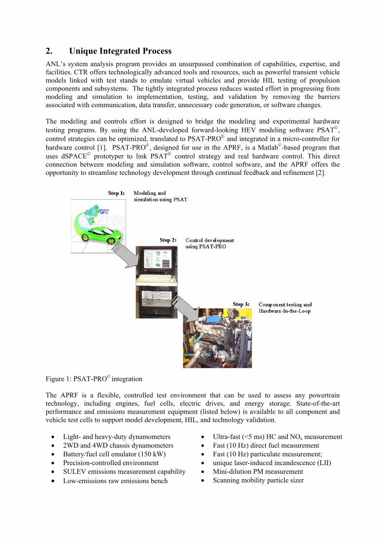
2. Unique Integrated Process ANL’s system analysis program provides an unsurpassed combination of capabilities, expertise, and facilities. CTR offers technologically advanced tools and resources, such as powerful transient vehicle models linked with test stands to emulate virtual vehicles and provide HIL testing of propulsion components and subsystems. The tightly integrated process reduces wasted effort in progressing from modeling and simulation to implementation, testing, and validation by removing the barriers associated with communication, data transfer, unnecessary code generation, or software changes. The modeling and controls effort is designed to bridge the modeling and experimental hardware testing programs. By using the ANL-developed forward-looking HEV modeling software PSAT, control strategies can be optimized, translated to PSAT-PRO and integrated in a micro-controller for hardware control [1]. PSAT-PRO, designed for use in the APRF, is a Matlab©-based program that uses dSPACE© prototyper to link PSAT control strategy and real hardware control. This direct connection between modeling and simulation software, control software, and the APRF offers the opportunity to streamline technology development through continual feedback and refinement [2].
Figure 1: PSAT-PRO© integration The APRF is a flexible, controlled test environment that can be used to assess any powertrain technology, including engines, fuel cells, electric drives, and energy storage. State-of-the-art performance and emissions measurement equipment (listed below) is available to all component and vehicle test cells to support model development, HIL, and technology validation.
• Light- and heavy-duty dynamometers • Ultra-fast (<5 ms) HC and NOx measurement • 2WD and 4WD chassis dynamometers • Fast (10 Hz) direct fuel measurement • Battery/fuel cell emulator (150 kW) • Fast (10 Hz) particulate measurement; • Precision-controlled environment • unique laser-induced incandescence (LII) • SULEV emissions measurement capability • Mini-dilution PM measurement • Low-emissions raw emissions bench • Scanning mobility particle sizer
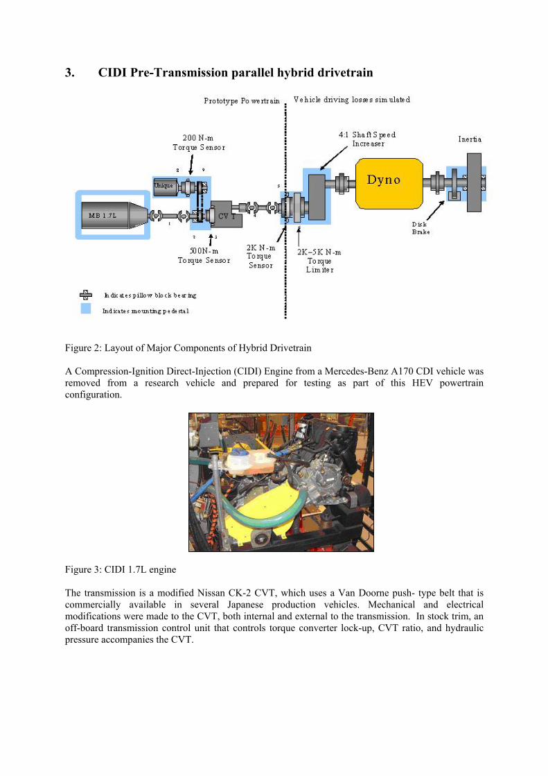
3. CIDI Pre-Transmission parallel hybrid drivetrain
Figure 2: Layout of Major Components of Hybrid Drivetrain
A Compression-Ignition Direct-Injection (CIDI) Engine from a Mercedes-Benz A170 CDI vehicle was removed from a research vehicle and prepared for testing as part of this HEV powertrain configuration. Figure 3: CIDI 1.7L engine The transmission is a modified Nissan CK-2 CVT, which uses a Van Doorne push- type belt that is commercially available in several Japanese production vehicles. Mechanical and electrical modifications were made to the CVT, both internal and external to the transmission. In stock trim, an off-board transmission control unit that controls torque converter lock-up, CVT ratio, and hydraulic pressure accompanies the CVT.
Figure 3:1.7l CIDI Engine

This was eliminated and all CVT control is done with the PSAT-PRO computer; additional hardware has been added to support this approach. The other main modification to the CVT was removal of the internal high-pressure hydraulic pump. It was replaced with an off-board pump. By fitting an external pump, much higher power transmission efficiencies can be realized. Figure 4: Modified Nissan CVT A hydraulic friction brake was designed to provide the retarding torque that a vehicle would need during an aggressive driving cycle. Two calipers are used on the same disk so that no radial force is applied to the rotating shaft and the calipers act as a couple. The calipers, disk, and master cylinder are automotive aftermarket units, typically used in racing applications. The control of the system is provided by PSAT-PRO. To translate this to a brake pressure (and resulting torque), an air control system was designed to operate the hydraulic automotive master cylinder. A high-precision pneumatic regulating valve takes the analog command from the PSAT-PRO computer and provides a proportional air pressure output. The output pressure then enters a pneumatic cylinder that provides the mechanical force to the automotive hydraulic master cylinder via a linkage. The hydraulic pressure from the master cylinder actuates the calipers.
Piston linkage
pn Pneumatic cylinder
Master brake cylinder
Dual piston brake
calipers
Figure 5: Disc Brake and Controller
High-precision eumatic regulating
valve

The flywheels were sized to provide the inertia required for the mass of the simulated vehicle.
Figure 6: Inertia flywheels The motor, a 45-kW DC brushless permanent magnet traction drive system (UQM), introduces the electrical torque into the powertrain by the use of a flatis a Woods QT Power Chain specifically made for high-torque applications. Fsimulating the components in an actual vehicle, the components were designedminimum. Figure 7: DC brushless permanent magnet electric motor
4. Control System description The hybrid powertrain is controlled with PSAT-PRO©. Specifically, the compuvehicle controller controls the torque of the powertrain to track a simulated vehspeed of the transmission output shaft (corresponding to the wheels) is measpeed feeds the vehicle model to determine the vehicle losses in these condtorque losses that would be produced in reality by the vehicle’s aerodynamicslosses are sent to the dynamometer as a torque command. The powertrain conin Figure 8 and the overall concept is shown in Figure 9. Figure 8: HIL hybrid powertrain control computer using PSAT-PRO©
Rotating arbor andinertia flywheel
Stationary, optional flywheels can be
attached to arbor if additional inertia is
required
from Unique Mobility -toothed belt. The belt or greater accuracy in
to keep the inertia to a
ter-based PSAT-PRO© icle speed profile. The sured. This measured itions. To simulate the , the calculated vehicle trol computer is shown
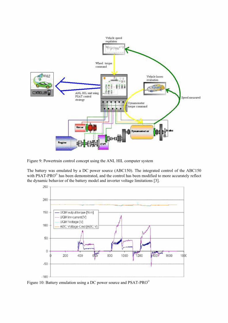
Figure 9: Powertrain control concept using the ANL HIL computer system The battery was emulated by a DC power source (ABC150). The integrated control of the ABC150 with PSAT-PRO has been demonstrated, and the control has been modified to more accurately reflect the dynamic behavior of the battery model and inverter voltage limitations [3]. Figure 10: Battery emulation using a DC power source and PSAT-PRO©

To control the engine accurately, a throttle position signal to actual engine torque conversion was needed. Two approaches have been evaluated for this transient torque prediction: a steady-state map lookup table and a neural net model based on the CTR’s emissions predictor work. Compared with test data (Figure 11), the neural net model prediction was somewhat better.
Figure 11: Engine torque control comparison (test data - red, map model - blue, NN model - green) Two fuzzy logic-based control strategies have been developed for this parallel hybrid powertrain using PSAT©: a fuel-economy-based strategy and an emissions reduction strategy. The fuel-economy-based power controller optimizes the power flow between the main components of the powertrain and optimizes the energy generation and conversion in the individual components (CIDI engine, electric motor, CVT, and battery). The efficiency maps of the components have been used to design this controller [4].
5. Analysis of Initial Results The integration of the propulsion systems in CTR test facilities and the emulation of realistic loads using validated HEV models have been commissioned by using the default control strategy. The optimized fuzzy logic control strategy will then be implemented to evaluate the full potential of CIDI engine for HEV applications. The following speed curves show the CVT ratio change needed to keep the engine at an optimal speed range. This specific control strategy has been designed to evaluate the engine start and clutch engagement process in different conditions. Therefore, the engine does not start when it is more efficient to operate in hybrid mode than in electric only mode; instead, it starts when the engine operation set point represents an interesting situation to test the clutch engagement process. During each engine start, the engine speed reached the speed of the input shaft of the transmission before smoothly engaging the clutch to obtain better driveability.
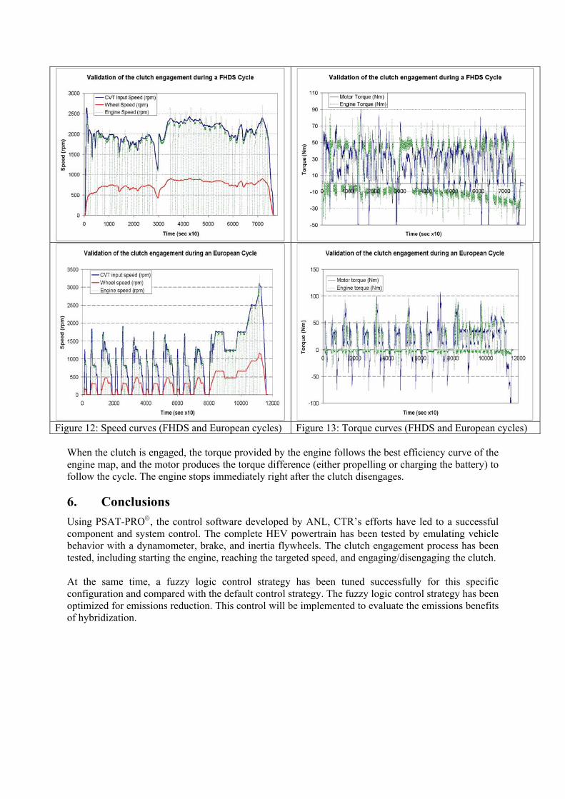
Figure 12: Speed curves (FHDS and European cycles) Figure 13: Torque curves (FHDS and European cycles)
When the clutch is engaged, the torque provided by the engine follows the best efficiency curve of the engine map, and the motor produces the torque difference (either propelling or charging the battery) to follow the cycle. The engine stops immediately right after the clutch disengages.
6. Conclusions Using PSAT-PRO, the control software developed by ANL, CTR’s efforts have led to a successful component and system control. The complete HEV powertrain has been tested by emulating vehicle behavior with a dynamometer, brake, and inertia flywheels. The clutch engagement process has been tested, including starting the engine, reaching the targeted speed, and engaging/disengaging the clutch. At the same time, a fuzzy logic control strategy has been tuned successfully for this specific configuration and compared with the default control strategy. The fuzzy logic control strategy has been optimized for emissions reduction. This control will be implemented to evaluate the emissions benefits of hybridization.

7. Acknowledgments This work was supported by the U.S. Department of Energy, under contract W-31-109-Eng-38. The authors would like to thank the U.S. Department of Energy, which sponsors this activity. The authors would finally like to thank USCAR members for their support.
8. References [1] A. Rousseau, S. Pagerit, G. Monnet, and A. Feng, The New PNGV System Analysis Toolkit PSAT V4.1 –
Evolution and Improvement, Future Transportation Technology (FTT) Conference, 2001, FTT01-50
[2] M. Pasquier and A. Rousseau, PSAT and PSAT-PRO, an Integrated and Validated Toolkit from Modeling to Prototyping, SAE World Congress, 2001, 01P-178
[3] M. Pasquier, M. Duoba, and A. Rousseau, Validating Simulation Tools for Vehicle System Studies Using Advanced Control and Testing Procedure, 18th Electric Vehicle Symposium (EVS18), October 20-24 2001, Berlin, Germany
[4] A. Rousseau, M. Pasquier, S. Saglini, J. Anderson, and K. Hardy, Trade-Offs Between Fuel Economy and Nitrous Oxide Emissions Using Fuzzy Logic Control with Hybrid CVT Configuration, 19th International Battery, Hybrid and Fuel Cell Electric Vehicle Symposium (EVS19), October 19-23 2002, BEXCO, Busan, Korea
9. Contacts Maxime Pasquier Argonne National Laboratory, 9700 South Cass Ave., ES/362-H220, Argonne, IL 60439-4815 Tel: 630-252-9717 Fax 630-252-3443 E-mail: [email protected] Mike Duoba Argonne National Laboratory, 9700 South Cass Ave., ES/362-C281, Argonne, IL 60439-4815 Tel: 630-252-6398 Fax 630-252-3443 E-mail: [email protected] Keith Hardy Argonne National Laboratory, 9700 South Cass Ave., ES/362-B201, Argonne, IL 60439-4815 Tel: 630-252-3088 Fax 630-252-3443 E-mail: [email protected] Aymeric Rousseau Argonne National Laboratory, 9700 South Cass Ave., ES/362-H220, Argonne, IL 60439-4815 Tel: 630-252-7261 Fax 630-252-3443 E-mail: [email protected] Dave Shimcoski Argonne National Laboratory, 9700 South Cass Ave., ES/371, Argonne, IL 60439-4815 Tel: 630-252-3156 Fax 630-252-3443 E-mail: [email protected]
The submitted manuscript has been created by the University of Chicago as Operator of Argonne National Laboratory (“Argonne”) under Contract No. W-31-109-ENG-38 with the U.S. Department of Energy. The U.S. Government retains for itself, and others acting on its behalf, a paid-up, nonexclusive, irrevocable worldwide license in said article to reproduce, prepare derivative works, distribute copies to the public, and perform publicly and display publicly, by or on behalf of the Government.