Embed Size (px)
Citation preview

DEPARTMENT OF THE AIR FORCE HEADQUARTERS AIR FORCE CIVIL ENGINEER SUPPORT AGENCY
JUL 19 2004
FROM: AFCESA/CES 139 Barnes Drive, Suite 1 Tyndall AFB FL 32403-5319 SUBJECT: Engineering Technical Letter (ETL) 04-2 (Change 1): Standard Airfield
Pavement Marking Schemes 1. Purpose. This ETL provides layout and dimensional criteria for airfield pavement markings. Major commands (MAJCOM) implementing tone down markings should follow the guidance in North Atlantic Treaty Organization Standardization Agreement (NATO STANAG) 3111, Airfield Marking Tone Down, and Air Standardization Coordinating Committee (ASCC) Air Standard 90/28, Aerodrome Pavement Markings. This ETL supersedes ETL 94-01, Standard Airfield Pavement Marking Schemes. 2. Application. This ETL applies to all Air Force activities except those operating at airports owned and controlled by an authority other than the Department of Defense (DOD). For airports under Federal Aviation Administration (FAA) jurisdiction, use FAA Advisory Circular (AC) 150/5340-1, Standards for Airport Markings. For cases where a Status of Forces Agreement (SOFA) specifically requires international standards, use International Civil Aviation Organization (ICAO) Annex 14, Volume I, Aerodromes (for fixed wing runways) or Annex 14, Volume II, Heliports (for rotary wing helipads and runways), as appropriate.
2.1. Authority: Air Force Policy Directive (AFPD) 32-10, Installations and Facilities, and Air Force Instruction (AFI) 32-1042, Standards for Marking Airfields. 2.2. Effective Date: Immediately. 2.3. Intended Users: Designers of Air Force airfield pavement markings.
2.4. Coordination:
!" MAJCOM pavements engineers !" Air Force Flight Standards Agency, Airfield Management Division
(AFFSA/XAM) 3. Referenced Publications.
3.1. Air Force: !" AFI 13-217, Drop Zone and Landing Zone Operations, available at
http://www.e-publishing.af.mil/
APPROVED FOR PUBLIC RELEASE: DISTRIBUTION UNLIMITED
Downloaded from http://www.everyspec.com

!" AFI 14-205, Identifying Requirements for Obtaining and Using Geospatial Information and Services, available at http://www.e-publishing.af.mil/
!" AFPD 32-10, Installations and Facilities, available at http://www.e-publishing.af.mil/
!" AFI 32-1042, Standards for Airfield Marking, available at http://www.e-publishing.af.mil/. This AFI provides specific requirements for marking Air Force runways and taxiways, names material specifications that can be used to obtain environmentally acceptable products for marking airfield pavements, and indicates who must accomplish the various tasks associated with this responsibility.
!" AFI 32-1044, Visual Air Navigation Systems, available at http://www.e-publishing.af.mil/. This AFI gives information on aircraft arresting system locations and lighted signs required for runway, taxiway, and instrument hold positions.
!" Air Force Manual (AFMAN) 32-1076, Design Standards for Visual Air Navigation Facilities, available at http://www.e-publishing.af.mil/.
!" Technical Order (T.O.) 36-1-191, Technical and Managerial Reference for Motor Vehicle Maintenance
!" ETL 04-7, C-130 and C-17 Landing Zone (LZ) Dimensional, Marking, and Lighting Criteria, available at http://www.afcesa.af.mil/library/etl.asp?Category=Engineering%20Technical%20Letters
3.2. Army:
!" ETL 1110-3-394, Engineering and Design – Aircraft Characteristics for Airfield-Heliport Design and Evaluation, available at http://www.usace.army.mil/inet/usace-docs/eng-tech-ltrs/etl1110-3-394/toc.htm
3.3. Joint Publications:
!" Unified Facilities Criteria (UFC) 3-260-01, Airfield and Heliport Planning and Design, available at http://65.204.17.188//report/doc_ufc.html
3.4. Department of Transportation (DOT), Federal Highway Administration (FHWA):
!" Manual on Uniform Traffic Control Devices for Streets and Highways, available at http://mutcd.fhwa.dot.gov/
3.5. FAA:
!" AC 70/7460-1, Obstruction Marking and Lighting, available at http://www.faa.gov/ats/ata/ai/circV.pdf
!" AC 150/5300-13, Airport Design, available at http://www.faa.gov/arp/150acs.cfm
!" AC 150/5340-1, Standards for Airport Markings, available at http://www.faa.gov/arp/150acs.cfm
!" AC 150/5345-55, Lighted Visual Aid to Indicate Temporary Runway Closure, available at http://www.faa.gov/arp/150acs.cfm
2
Downloaded from http://www.everyspec.com

3.6. Federal Specifications:
!" TT-P-1952, Paint, Traffic and Airfield Marking, Waterborne, available at http://apps.fss.gsa.gov/pub/fedspecs/
!" TT-B-1325, Beads, Retroreflective, available at http://apps.fss.gsa.gov/pub/fedspecs/
3.7. North Atlantic Treaty Organization (NATO):
!" STANAG 3111, Airfield Marking Tone Down 3.8. ASCC:
!" Air Standard 90/28, Aerodrome Pavement Markings 3.9. ICAO:
!" Annex 14, Volume I, Aerodromes !" Annex 14, Volume II, Heliports
4. Acronyms: AFI - Air Force Instruction AFFSA - Air Force Flight Standards Agency AFMAN - Air Force Manual AFPD - Air Force Policy Directive ASCC - Air Standardization Coordinating Committee ATC - air traffic control DME - distance measuring equipment DOD - Department of Defense DTG - distance-to-go ETL - Engineering Technical Letter FAA - Federal Aviation Administration FHWA - Federal Highway Administration HAT - height above touchdown ICAO - International Civil Aviation Organization ILS - Instrument Landing System IMC - Instrument Meteorological Conditions INS - Inertial Navigation System LZ - Landing Zone MAJCOM - major command MOS - Minimum Operating Strip NATO - North Atlantic Treaty Organization NAVAID - navigational aid NOTAM - Notice to Airmen PAR - Precision Approach Radar SOFA - Status of Forces Agreement STANAG - Standardization Agreement TACAN - Tactical Air Navigation
3
Downloaded from http://www.everyspec.com

VFR - Visual Flight Rules VOR - VHF Omni Range 5. Materials.
5.1. Permanent Markings. Use paint and retroreflective glass beads to apply runway markings. Use paint or preformed materials such as retroreflective marking tape, or thermoplastic and retroreflective glass beads to apply taxiway, helipad, or apron markings. Secondary taxiway and apron markings, shoulder markings (deceptive surfaces), closed pavement markings, and overrun chevrons need not be reflectorized; however, application of beads to these markings is preferred if they are to be used during periods of reduced visibility or darkness.
5.1.1. Use lead-free waterborne paint obtained under Federal Specification TT-P-1952, Paint, Traffic and Airfield Marking, Waterborne. Select Type I, Ten Minute No Pick-Up Time, or Type II, Fast Dry, High Humidity Formula. 5.1.2. For all retroreflective markings, use glass beads available under Federal Specification TT-B-1325, Beads, Retroreflective, Type I, Gradation A.
5.2. Temporary Markings. Mark paved or unpaved surfaces with lime and water solutions (whitewash) or sea marker dye. Paved taxiway and apron surfaces may also be temporarily marked using preformed marking tape. When using whitewash to apply temporarily displaced threshold markings, the chevrons and arrowheads may be white. Do not use preformed marking tape on runways.
Exception: Tape may be used to mark a temporarily displaced threshold if aircraft will not traverse the area at greater than normal taxi speeds and the tape will not be exposed to jet blast during takeoff and landing. These materials can be easily dislodged by jet blast, creating the potential for foreign object damage to jet engines.
5.2.1. Where white markings do not provide the required contrast (e.g., snow-covered surfaces), a colored dye, such as sea-marker dye (yellow-green or yellow-orange), must be used.
5.2.2. Barricades (Figure 16) or portable edge markers (Figure 21) can be used instead of pavement markings during construction or for expedient airfield markings, such as for a Minimum Operating Strip (MOS). Use frangible markers designed and constructed of materials that will collapse if struck by an aircraft. They must be colored to present a sharp contrast with the surrounding terrain.
5.3. Application Rates. The best application rate for paints and preformed materials varies depending on the intended purpose of the marking and the physical properties of the material. Some common applications are described below.
4
Downloaded from http://www.everyspec.com

5.3.1. Paint.
5.3.1.1. Fully Cured Pavement. Apply paint at a wet film thickness of 0.305 millimeter to 0.356 millimeter (12 mils to 14 mils) for a desired dry film thickness of approximately 0.203 millimeter (8 mils). This thickness is needed to properly bind retroreflective beads in the paint. At this rate, coverage will be approximately 3 square meters per liter (121 square feet per gallon). 5.3.1.2. New Pavement. If new pavement surfaces must be opened to operations before being allowed to fully cure, apply temporary markings on new pavement at an application rate that will result in a dry film thickness of 0.102 millimeter to 0.152 millimeter (4 mils to 6 mils); this will produce a marking of sufficient prominence to allow operations. Touch up the marking in the event of bleeding, and remark the pavement at the normal application rate after the pavement is thirty days old.
5.3.2. Apply thermoplastics and preformed reflective tape in accordance with the manufacturer's instructions. 5.3.3. Apply retroreflective media (glass beads) at approximately 3.6 kilograms to 3.9 kilograms per 11.2 square meters (8 pounds to 9 pounds per gallon of paint or 121 square feet) of marked surface area. 5.3.4. Painted markings should not be allowed to build up beyond a total thickness of approximately 1.02 millimeters (40 mils). This will occur after about five marking cycles unless surface abrasion (such as can be caused by snow-removal equipment) reduces this buildup. Over-painting will cause the marking to eventually crack and peel.
5.3.5. To minimize hook-skip potential, ensure paint buildup does not exceed 3.1 millimeters (0.125 inch) within 61 meters (200 feet) on either side of the aircraft arresting system pendant.
6. Runway Markings.
6.1. There are three patterns for marking runways: basic, nonprecision instrument approach, and precision instrument approach. See Figure 1.
5
Downloaded from http://www.everyspec.com

LEGEND
PAVEMENT EDGE
PAINTED MARKINGS
Precision Instrument Non-Precision Instrument Basic Runway
Threshold Markings
Fixed Distance Markings
Touchdown Zone
Markings
Touchdown Zone
Markings
Touchdown Zone
Markings
Touchdown Zone
Markings
Side Stripes
Centerline Markings
Runway Designation
Markings
Fixed Distance Markings
Figure 1. Runway Marking Schemes
6
Downloaded from http://www.everyspec.com
6.2. Runway Centerline.
6.2.1. Runway centerlines are marked with a series of uniformly spaced longitudinal stripes. They are 914 millimeters (3 feet) wide on non-precision instrument approach and precision instrument approach runways and at least 457 millimeters (1.5 feet) wide for basic runways. Begin the layout of centerline markings 12.2 meters (40 feet) inward from the runway designation marking (numerals), and continue to the midpoint of the runway. Adjust the lengths of stripes and gaps to accommodate runway length near the runway midpoint. Typically, adjustment will not involve more than two stripes and three gaps, or three stripes and two gaps, depending on which of the two falls at the center point of the runway. Figure 2 shows the layout detail for centerline markings.
7
Downloaded from http://www.everyspec.com

A B C D C
FF
E
G
J
H
J
!
LB
K
Edge of thefull strengthpavement
DIMENSIONABCDEFGH
I (See par. 6.5.2)JKL
FEET20.0
100.040.030.012.0
6.05.0
1.5–3.070–72/97
3.0150/200/300
60.0
METERS6.10
30.5012.209.153.661.831.52
0.46–0.9221.36–21.94/29.56
0.91445.7/60.9/91.4
18.29
NOTE: Add two threshold bars each side of runway if side stripes are laid out to depict a 60.9 m(200 ft) wide runway.
See Note
Figure 2. Threshold, Designation Number, Side Stripe, and Centerline Layout
6.2.2. Former Air Force Regulation (AFR) 88-16, Standards for Marking Airfields, promulgated threshold and designation markings which were longer than the current standard. Changing these markings to meet the new standard dimensions creates a gap 36.6 meters (120 feet) long between the new
8
Downloaded from http://www.everyspec.com

designation marking and the first existing centerline stripe. To fill this gap, you may mark an additional centerline stripe 12.2 meters (40 feet) long between the designation marking and the first centerline stripe. In cases of parallel runways where a letter is added to the designation marking, the additional centerline stripe must be 21.3 meters (70 feet) long. In either case, the additional stripe is placed equidistant between the designation marking and the first existing centerline stripe. In this way, changes to the centerline stripe layout scheme may be deferred pending a new overlay or reconstruction project.
6.3. Threshold Marking. The threshold is the beginning of the full-strength pavement. Thresholds are marked with a group of longitudinal stripes beginning 6.1 meters (20 feet) inward from the full-strength pavement. They are spaced symmetrically about the runway centerline. Figure 2 shows the layout detail for thresholds.
6.3.1. Mark displaced thresholds by repositioning the standard threshold marking at the new threshold. Place a transverse stripe on the pavement preceding the threshold. Extend the transverse stripe from side stripe to side stripe. Dimensions and layout details are shown in Figure 3. Exception: Repositioning is not required for temporarily displaced thresholds.
9
Downloaded from http://www.everyspec.com

ABCDEFHJKLMNPR
140–144/1946.0
12.04.010.020.016.0100.0
Variable60.00.5
1.5–3.030.03.0
42.72–43.89/59.131.8303.6601.2203.0486.1004.876
30.500Variable18.2880.152
0.460–0.9209.1500.914
DIMENSION FEETMETERS
C
BB
R
D
F
H
BB B
P N
N
E
J J
M
R
LKJ
E
A
STANDARD THRESHOLD MARKINGS
CENTERLINE MARKING
DISPLACED THRESHOLD MARKINGS
D
PE
R
D
NOTE: ON RUNWAYS 60.96 m (200') AND WIDER, ADD TWO ADDITIONAL THRESHOLD BARS ON EACH SIDE OF CENTERLINE IF SIDE STRIPES ARE LAID OUT TO DEPICT A 60.96 m (200') WIDE RUNWAY. SEE FIGURE 2 AND PARAGRAPH 6.5.
Figure 3. Typical Displaced Threshold Layout on 45.7-Meter (150-Foot) Wide Runway
6.3.2. There are four different schemes that may be used to mark the pavement in the displaced area. Select a scheme from those shown in Figure 4 that will suit the intended use of the area.
10
Downloaded from http://www.everyspec.com

STANDARD THRESHOLDMARKINGS
DISPLACED THRESHOLD MARKINGS
DISPLACED THRESHOLD MARKINGS WHERERUNWAY SURFACE IS USED FOR AIRCRAFTTAKE-OFF
DISPLACED THRESHOLD MARKINGS
STANDARD THRESHOLDMARKINGS
STANDARD THRESHOLDMARKINGS
DISPLACED THRESHOLD MARKINGS WHERERUNWAY SURFACE IS USED AS A TAXIWAY
DISPLACED THRESHOLD MARKINGS WHEREABANDONED RUNWAY SURFACEIS NOT USEDFOR AIRCRAFT MOVEMENT.
TEMPORARILY DISPLACED THRESHOLD MARKINGS FOR CONSTRUCTION PURPOSES.NOTE: OTHER EXISTING RUNWAY MARKINGS WITHIN THE DISPLACED THRESHOLD AREA NEED NOT BE OBLITERATED.
STANDARD OVERRUN MARKINGS
STANDARD THRESHOLD MARKINGS
TAXIWAY CENTERLINE MARKING
RUNWAY HOLDINGPOSITION
RUNWAY HOLDINGPOSITION
(a)
(b)
(c)
(d)
Figure 4. Displaced Threshold Area Marking Schemes
11
Downloaded from http://www.everyspec.com

6.4. Runway Designation. Designation markings indicate the magnetic azimuth of the runway centerline to the nearest 10-degree increment. The designation consists of two numbers, or in the case of parallel runways, two numbers and a letter.
6.4.1. Numbers are formed with 762-millimeter (2.5-foot) wide vertical stripes and 1524-millimeter (5-foot) wide horizontal stripes. A zero precedes all single-digit numbers. Lateral spacing between the numbers is 3048 millimeters (10 feet) except for the numbers "10" and "11." Spacing between numerals for these runway designations are 2286 millimeters (7.5 feet) and 3810 millimeters (12.5 feet), respectively. A typical layout is shown in Figures 2 and 5.
12
Downloaded from http://www.everyspec.com

DIMENSION
ABCDEFGH
FEET
1.02.53.55.06.57.07.58.0
MILLI-METERS
305762
106615241981213422862438
DIMENSION
JKLMNPQR
FEET
8.59.09.5
10.011.512.012.513.0
MILLI-METERS
25902743289630483505365838103962
DIMENSION
STUVWXY
FEET
13.516.017.018.018.520.030.0
MILLI-METERS
4115487751825486563960969144
MB
BA
M Q M
MGM X
M
M M M
M
Q
W
Y
Y
Y
S
PK K
DL
TN
CC
C
V
J
H
E D
D
D
D
QF
T
F
SE
XD
R
W
DE
EU
D
A
N
Figure 5. Runway Designation Numbers and Letters
13
Downloaded from http://www.everyspec.com

6.4.2. For parallel runways mark "L," "R," or "C" to represent left, right, or center runway (viewed from the approach) between the threshold (or threshold marking) and the designation marking. The longitudinal spacing between the threshold (or threshold marking) and the letter is 12.2 meters (40 feet). Letters are 9.1 meters (30 feet) long. The longitudinal spacing between the letter and the number is 12.2 meters (40 feet). Letters are formed with 762-millimeter (2.5-foot) wide vertical stripes and 1524-millimeter (5-foot) wide horizontal stripes. Dimensions are given in Figure 5.
6.5. Side Stripes. Side stripes must be marked on precision instrument runways and may also be used on non-precision instrument runways and basic runways. Do not use these lines to identify the edge of the usable pavement—they are intended only to enhance visual acquisition of the runway environment. If there is a lack of contrast between the load-bearing surface and the shoulder, use shoulder markings (deceptive surface) on the non-load-bearing surface. Note: If there is a significant gap between the deceptive surface markings and the runway side stripe (such as can occur when side stripes are spaced at 43.9-meter [144-foot] separation on a 91.4-meter [300-foot] wide runway), double 152-millimeter (6-inch) wide yellow stripes, separated by a 152-millimeter (6-inch) wide gap, may be added to the inner ends of the deceptive surface markings to longitudinally delineate the limit of the load-bearing pavement. An example of this situation is shown in Figure 8. Stripe details are the same as for a taxiway or apron edge stripe. Place the outer edge of the outermost stripe to coincide with the edge of the full-strength pavement and the inner end of the deceptive surface marking. These stripes should be curved to follow the outer edge of fillets and terminate at the intersecting taxiway edge, or joined to taxiway edge markings, if used.
6.5.1. The markings consist of two continuous stripes placed symmetrically about the runway centerline. These stripes begin 12.2 meters (40 feet) inward from the threshold marking and continue to within 12.2 meters (40 feet) of the threshold marking on the opposite end of the runway (Figure 2). Where a displaced threshold exists, terminate the side stripe at the transverse threshold mark (with exception to temporary displaced threshold markings) and resume 914 millimeters (3 feet) from the repositioned standard threshold markings. (Note that side stripes are not used for overruns or a displaced threshold area used as a taxiway.) The outer edge of the stripes may be positioned up to 914 millimeters (3 feet) inboard from the runway edge, but maintain a minimum separation of 42.7 meters (140 feet) between the inner edges of the stripes on 45.7-meter (150-foot) wide runways. 6.5.2. Side stripes may be placed at a separation distance of 42.7 meters (140 feet), regardless of the runway width. If special missions indicate a need for wider separation on 61- or 91-meter (200- or 300-foot) wide runways, the side stripes
14
Downloaded from http://www.everyspec.com

are placed as stated in paragraph 6.5.1, except the separation between the inner edges of the stripes is 59 meters (194 feet); greater separation is not authorized.
6.6. Touchdown Zone and Fixed Distance Markings.
6.6.1. Touchdown zone markings consist of pairs of longitudinal stripes placed symmetrically about the centerline. Three stripes are provided in the first two pairs, two stripes in the next two pairs, and single stripes in the last two pairs. The lateral distance between each pair of longitudinal stripes measured at their inner edges is a constant 21.9 meters (72 feet). Omit any pair of markings that fall within 304.8 meters (1000 feet) of the runway midpoint. The layout and dimensions are shown in Figure 6.
15
Downloaded from http://www.everyspec.com

22.8
6 m
(75'
)22
.86
m(7
5')
21.95 m(72')
45.7
2 m
(150
')
304.8 m (1000')FROM THRESHOLD
152.4 m (500') FROM THRESHOLD
STRIPES1.83 m
(6')
GAPS1.53 m
(5')
SIDE STRIPES
Note 1: Fixed distance markers will be provided on all runways 1,219.2 m (4,000 ft) or longer. Substitute them for the second set of touchdown zone markings.
Note 2: Omit touchdown zone markings that will fall within 304.8 m (1,000 ft) of the runway midpoint.
SIDE STRIPES42.67 m (140’) to 43.90 m (144’), or
59.14 m (194’) between inner edges.
TOUCHDOWN ZONE MARKINGS
CENTERLINE STRIPES
FIXED DISTANCE MARKINGS (See Paragraph 6.6.2)
21.95 m(72')
9.14 m(30')
22.8
6 m
(75'
)
457.2 m (1500')FROM THRESHOLD
9.14 m(30')
609.6 m (2000')FROM THRESHOLD
22.8
6 m
(75'
)
21.95 m(72')
21.95 m(72')
21.95 m(72')
762 m (2500')FROM THRESHOLD
914.4 m (3000') FROM THRESHOLD
22.8
6 m
(75'
)22
.86
m(7
5')
TOUCHDOWN ZONE MARKINGS
TOUCHDOWN ZONE MARKINGS
Figure 6. Touchdown Zone and Fixed Distance Markings
6.6.2. Fixed Distance Markings. Provide fixed distance markings on runways that are at least 45.7 meters (150 feet) wide and at least 1219.2 meters (4000 feet)
16
Downloaded from http://www.everyspec.com

long. Substitute them in place of the second pair of touchdown zone markings. The layout plan and dimensions are shown in Figure 6.
6.7. Aircraft Arresting System Warning Markings. Mark aircraft arresting system locations on the runway with a series of discs placed beneath the pendant. Where touchdown zone and disc markings coincide, the touchdown zone marking is interrupted at that location for a minimum distance of 305 millimeters (1 foot) from the edge of the disc marking. If the designation and disc markings coincide, shift the designation marking longitudinally to eliminate the conflict. The layout plan and dimensions for these markings are shown in Figure 7. Do not use these markings in overruns.
ARRESTING SYSTEM WARNINGMARKING ARRANGEMENT WHENSACRIFICIAL PANELS ARE USED
PENDANT
1.52 m (5’) RADIUS SEMI-CIRCLES
SACRIFICIALPOLYETHYLENE
PANELS
RU
NW
AY
CE
NTE
RLI
NESID
ES
TRIP
E
SID
ES
TRIP
E
CE
NTE
RLI
NE
STR
IPE
2.29 m(7.5')
4.57 m(15')
3.05 m(10')
3.05 m(10')
3.05 m (10') DIAMETER DISCS
1.52 m (5')
4.57 m(15')
Figure 7. Aircraft Arresting System Warning Markings
6.8. Runway Overruns. Chevron markings are used on overruns to indicate the area is not an operational surface. The apex of the initial chevron is located on the runway centerline at the beginning of the full-strength pavement. The legs of the chevrons intersect the centerline at a 45-degree angle. On runways greater than 45.7 meters (150 feet) wide, the chevron legs may extend laterally beyond the runway threshold and side stripe markings; however, do not extend them beyond the
17
Downloaded from http://www.everyspec.com
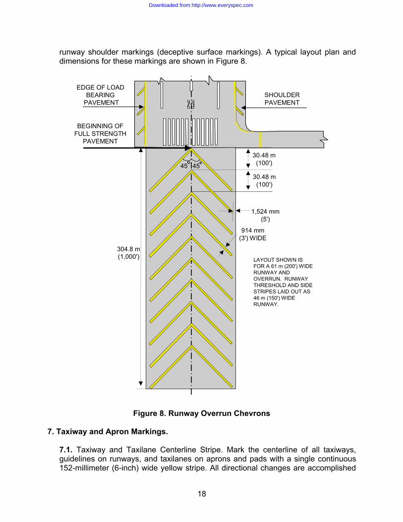
runway shoulder markings (deceptive surface markings). A typical layout plan and dimensions for these markings are shown in Figure 8.
BEGINNING OFFULL STRENGTH
PAVEMENT
304.8 m(1,000')
914 mm(3') WIDE
1,524 mm(5')
30.48 m(100')45 45
30.48 m(100')
LAYOUT SHOWN IS FOR A 61 m (200') WIDE RUNWAY AND OVERRUN. RUNWAY THRESHOLD AND SIDE STRIPES LAID OUT AS 46 m (150') WIDE RUNWAY.
SHOULDERPAVEMENT
EDGE OF LOADBEARING
PAVEMENT
Figure 8. Runway Overrun Chevrons 7. Taxiway and Apron Markings.
7.1. Taxiway and Taxilane Centerline Stripe. Mark the centerline of all taxiways, guidelines on runways, and taxilanes on aprons and pads with a single continuous 152-millimeter (6-inch) wide yellow stripe. All directional changes are accomplished
18
Downloaded from http://www.everyspec.com

with smooth curves. Nose wheel guidelines should be positioned to maintain a clearance of at least 3 meters (10 feet) between the aircraft's outermost main gear and the edge of the full-strength pavement when the cockpit is maintained over the nose wheel guideline through the turn. Also ensure adequate wingtip clearance is provided for the most demanding aircraft that will use the taxi route. Typical taxiway and other nose wheel guidelines are shown in Figure 9. On runways, the curve is tangent to a line parallel to and 914 millimeters (3 feet) from the near side of the runway centerline marking, and extends 60 meters (200 feet) beyond the point of tangency.
7.1.1. Typical taxilane locations for cargo aircraft aprons are provided in Attachment 1. Use Table A1.1 and Figure A1.1 to determine the appropriate turning radii. For aircraft not shown in Attachment 1, compute the distance from the adjacent taxiway or taxilane to provide the minimum wingtip clearance required by UFC 3-260-01, Airfield and Heliport Planning and Design, Table 6.1. Aircraft turning diagrams can be found in Army ETL 1110-3-394, Aircraft Characteristics for Airfield-Heliport Design and Evaluation. When marking an apron for a specific aircraft, coordinate with the airfield management and flight safety functions to ensure procedures are published in the Airfield Operating Instruction to ensure aircraft marshallers are used for other more demanding aircraft that may use the apron. 7.1.2. Stop blocks may be painted at aircraft parking positions to indicate the intended location for the aircraft nose wheel when parked. Stop blocks are painted reflective yellow and are 1 meter (3 feet) long and 333 millimeters (1 foot) wide, centered on and oriented perpendicular to the nose wheel guideline. See Table A1.1 and Figure A1.1. 7.1.3. On hammerheads, aprons, and pads, and at runway/taxiway and taxiway/taxiway intersections, the radius for the curve must be greater than the minimum turning radius for the assigned mission aircraft, and should be positioned to maintain a clearance of at least 3 meters (10 feet) between the outermost main gear of a C-5 and the edge of the full-strength pavement. See Army ETL 1110-3-394 for aircraft turning diagrams. The recommended radius for 90-degree runway/taxiway intersections is 45.7 meters (150 feet). The recommended radius for 90-degree taxiway/taxiway intersections is 38.1 meters (125 feet). Other radii can be used for these as well as other intersections, depending on local requirements. In all cases, ensure these radii will accommodate the pavement structure (clearance between outer main gear and edge of pavement) for the most demanding aircraft that will use the intersection before marking nose-wheel guidelines at these dimensions.
19
Downloaded from http://www.everyspec.com

EDGE OF RUNWAY
152 mm (6")STRIPESAND GAP
mm (6")
100'
TO
250
'30
.5 m
TO
76
m
914 mm (3')SPACES
914 mm (3')STRIPES
914 MM(3')
TAXIWAYSTRIPE 152 mm (6")
OLD NATO RUNWAYHOLD POSITION
152 mm (6")
152 mm (6")
152 mm (6")
152 mm (6")
152 mm (6")
152 mm (6")
4.572 m(15')
7.620 m(25')
TAXIWAY AND APRONEDGE MARKINGS
TAXILANE EDGE MARKINGS(OPTIONAL)
RUNWAY HOLD POSITION MARKING
INST
PROVIDE "INST" MARKING AT INTERVALS OF NOT MORETHAN 45 m (150') WHERE WIDTH OF MARKING EXCEEDS 60m (200')
305 mm (1')STRIPE
610 mm (2')
3.048 m (10')
305 mm(1')
305 mm (1')
305 mm (1')WIDE STRIPE
1829 mm (6')
TAXIWAY CL STRIPE152 mm (6")
914 mm (3')
INSTRUMENT HOLDINGPOSITION
914 mm (3') 914 mm (3') 914 mm (3')
RUNWAYCENTERLINE STRIPE
APRON
AREA
152 mm (6") WIDE TAXIWAYCENTERLINE STRIPE
OR NOSEWHEEL GUIDELINE
INST
610 mm(2’)
See Note 1 SHO
ULD
ER
PAVE
MEN
T
SHO
ULD
ER
PAVE
MEN
T
EDGE OF RUNWAY
152 mm (6")STRIPES
AND GAPS
(100
' TO
250
’)31
.5 m
TO
76
m
914 mm (3')SPACES
914 mm (3')STRIPES
914 mm(3')
TAXIWAYSTRIPE 152 mm (6")
See Note 1 SHO
ULD
ER
PAVE
MEN
T
SHO
ULD
ER
PAVE
MEN
T
914 mm(3')
1220 mm(4’)
See Note 1NOTES1. Extend all holding position markings across taxiway or apron shoulder pavement.2. Extend nose wheel guidelines 60m (200') beyond the point of tangency on runways.
See Note 2
0.5 Wingspan
plus Wingtip
Clearance from UFC 3-260-01, Table 6.1
LC
Figure 9. Taxiway Markings
20
Downloaded from http://www.everyspec.com

7.2. Holding Positions. Holding positions are necessary on all pavements that lead to an active runway or helipad. They designate a boundary intended to protect the runway or helipad environment from incursions and prevent interference with signals transmitted by electronic navigational aids. There are two basic patterns for marking hold positions: one is used to mark hold positions used for visual flight rule (VFR) conditions and the other is used to mark instrument (“INST”) hold positions. Figure 9 shows two ways to mark a VFR hold line and the layout for an instrument hold line. For VFR holding positions, the double dashed and double solid hold position marking is preferred (and should be programmed for the next marking cycle if not already in use). It replaces the outdated NATO single dashed and single solid hold position markings. Both VFR and instrument holding positions are marked from edge to edge of the pavement surface, including paved shoulders.
7.2.1. VFR Runway Holding Position. This holding position is located 30.5 meters to 76.2 meters (100 feet to 250 feet) from the near edge of the runway. The minimum setback from the runway edge is 30.5 meters (100 feet). This distance is measured perpendicular to the long axis of the runway. Calculate distances from the runway centerline by dividing the published runway width by 2 and adding the required clearance distance. Where practicable, setback distances for the VFR runway holding position should be increased for instrument runways and where the wingspan of the controlling aircraft is greater than 24 meters (79 feet). Suggested increased setback distances from the runway edge are: 53.3 meters (175 feet) for controlling aircraft with wingspans from 24 meters (79 feet) up to 52 meters (171 feet); and 62.5 meters (205 feet) for controlling aircraft with wingspans greater than 52 meters (171 feet). Increase these distances by 0.3 meter (1 foot) for each 30.5 meters (100 feet) of airfield elevation above sea level. The hold position may be placed parallel to the runway centerline on taxiways that enter at an angle to the runway. Note: For the Air Force, this ETL is the first publication of specific setback distances for VFR hold positions based on aircraft wingspan; therefore hold positions at many airfields will not meet the above distances. Additionally, because many airfields were constructed under previous standards, strict application of these increased setback distances may not be possible or operationally practicable at every installation. The information provided above should not be viewed as a basis for an immediate or mandatory change in the location of VFR holding positions at any given base. Furthermore, if VFR holding positions are relocated, obliteration by painting over the old marking is not acceptable; they must be completely removed. Changes in the locations of VFR holding positions should be implemented during a normal remarking cycle to minimize costs.
7.2.2. Instrument Holding Position. Runways served by precision instrument navigation aids may require an instrument holding position be marked in addition to the VFR holding position. Where practicable, collocate these markings and mark only the VFR holding position. If required, locate the instrument holding
21
Downloaded from http://www.everyspec.com

position further from the active runway to prevent taxiing or holding aircraft from interfering with signals transmitted to inbound aircraft during Instrument Meteorological Conditions (IMC). This hold position is configured differently from a VFR hold position and is augmented with the letters "INST" on the runway side of the line. The letters are to be read when facing the runway. They are marked in block letters 1829 millimeters (6 feet) high by 610 millimeters (2 feet) wide, spaced 305 millimeters (1 foot) apart. The letters are formed with a 152-millimeter (6-inch) stroke. The "INST" designator must be placed symmetrically between the taxiway centerline and the taxiway edge or edge marking on the left side of the centerline. For hold lines over 61 meters (200 feet) long, mark the "INST" designator at intervals not exceeding 45.7 meters (150 feet). Locations for the instrument hold line vary, depending on the type and capability of the landing aid; locate them in accordance with the following paragraphs.
7.2.2.1. Instrument Holding Position (Runway Served by Instrument Landing System [ILS]). If the height above touchdown (HAT) is 61 meters (200 feet) or greater (ask the airfield manager), mark the instrument holding position at the edge of the glide slope critical area. If the HAT is less than 61 meters (200 feet), mark the holding position at the edge of the touchdown area or the glide slope critical area, whichever is farther from the edge of the runway. The glide slope critical area and touchdown area are shown in Figure 10. The instrument hold line must be at least 152.4 meters (500 feet) from the runway centerline when the touchdown area criteria apply.
22
Downloaded from http://www.everyspec.com

3535
GLIDE SLOPE CRITICAL AREA
INST HOLD LINE
975.36 m(3200')
61 m(200')
VFR HOLD LINE
GLIDESLOPEANTENNA
INST HOLD LINE
396.24 m (1300') or to the end of the runway, whichever is greater.
152.4 m(500')
TOUCHDOWN AREA
INS
TINST
VFR HOLD LINE
152.4 m(500')
Figure 10. Locating Instrument Hold Line Positions
7.2.2.2. Instrument Holding Position (Runway Served by Precision Approach Radar [PAR]). Establish the instrument hold line at the edge of the touchdown area (Figure 10) if the PAR serving that runway has a HAT less than 61
23
Downloaded from http://www.everyspec.com

meters (200 feet). If the HAT is 61 meters (200 feet) or greater, no instrument hold position is needed. 7.2.2.3. In all cases ensure a VFR hold position is marked between all instrument hold positions and the active runway. However, if either of the following examples applies, mark a VFR hold line only if:
!" The runway hold line and the instrument hold line happen to fall at the same location, or
!" The additional taxi time required to move from the instrument hold position to the runway is operationally acceptable under VFR.
7.3. Taxiway, Taxilane, and Apron Edge Stripes.
7.3.1. Taxiway and Apron Edge Stripes. When there is little contrast between the taxiway or apron edge (or boundary) and the surrounding area, mark the edge of the full-strength pavement with two continuous 152-millimeter (6-inch) wide stripes separated by a 152-millimeter (6-inch) wide gap. This marking is used to delineate the edge of the taxiway or apron from other pavements or surfaces not intended for use by aircraft. It should never be used in areas where aircraft would be required to cross the designated boundary. Place this marking no more than 914 millimeters (3 feet) inward from the edge of the full-strength pavement. No portion of the marking should be placed on non-load-bearing pavements. Use the tangents for the taxiway centerline stripe on curves; in areas where this is not practical, use the edge of the full-strength pavement. Figure 9 shows a typical edge line layout, the width of the stripes, and the space between them. 7.3.2. Taxilane Edge Stripes. This marking is used to define the limits of a designated taxi route where the surrounding pavement is intended for use by aircraft. Aircraft movement across the designated boundary is permitted either by direction of air traffic control (ATC), a marshaller, or at the pilot's discretion. This marking consists of two 152-millimeter (6-inch) wide broken stripes separated by a gap 152 millimeters (6 inches) wide. The stripes are 4.6 meters (15 feet) long with gaps of 7.6 meters (25 feet). The detail and a typical layout are shown in Figure 9. Place the innermost edge of each stripe a distance from the centerline equal to half the wingspan of the most demanding aircraft that uses the taxilane, plus the appropriate wingtip clearance required by UFC 3-260-01, Table 6.1, item 5 or 6.
7.4. Taxiway Identification. Taxiway identification signs are described in AFI 32-1076. Where it is desirable to furnish additional guidance at intersections, the information may be provided on the taxiway before the intersection. Runway and taxiway identification numbers and letters are marked in 1829 milimeter (6-foot) by 610-millimeter (2-foot) block letters formed with a 152-millimeter (6-inch) stroke. Provide an arrow above the identifier to show direction. Figure 11 shows typical identification numbers and letters. In cases where double letters or a letter and a
24
Downloaded from http://www.everyspec.com

number are used in combination (e.g., DD or D1), separate the digits with a 0.6-meter (2-foot) gap.
IDENTIFICATION WILL BE 1829 mm (6')HIGH BLOCK LETTERS AND/OR NUMBERSUSING A 152mm (6") STROKE.
EDGE MARKINGIF REQUIRED
PAVED SHOULDER
RUNWAY CENTERLINE
25 07
D
D
TAXIWAY "D"
AA
D
D
TO APRONTO RUNWAYEND 25
TAXIWAY CENTERLINE STRIPE
TAXIWAY “A”
1829 mm(6’)
610 mm(2’)
61 m (200')
1 m(3')
600 mm(2')
600 mm(2')
45°
600 mm(2')
460 mm(1.5')
071200 mm
(4')
Taxiway Centerline
914 mm(3')
15 m(50')
D
152 mm
(6')
RUNWAY EDGE
PAVED SHOULDER
Figure 11. Taxiway and Runway Identification
25
Downloaded from http://www.everyspec.com

8. Helipads.
8.1. Helipad Perimeter and Identification Markings.
8.1.1. Mark a perimeter boundary with a capital "H" in the center to identify a pad intended for helicopter operations. If the landing area is a runway, mark a capital "H" at the midpoint of the runway, centered on the pavement. Orient the “H” so it is aligned with the normal direction of approach (appears as an “H” to pilots during their approach to landing). If the facility is intended for single-direction ingress and egress, mark a bar beneath the “H” to show the intended direction of approach/departure. A bar may also be placed under the “H” when it is necessary to distinguish the preferred approach direction for bidirectional helipads. The length of the bar should be at least equal to the overall width of the “H” and the width equal to Dimension C in Figure 12. Provide a space between the “H” and the bar equal to half of the bar width. The perimeter boundary marking consists of a broken square marked at the corners and along the edges to delineate the limits of the safe touchdown area. The boundary must be sized to accommodate the overall length of the largest helicopter using the facility. Figure 12 provides dimensions and layout details.
26
Downloaded from http://www.everyspec.com

C
C
B
B
F
E
F A
D
IDENTIFIER DIMENSIONS
DIMENSION A =0.6 OF DIMENSION F (MAXIMUM OF 20.12 m [66’])DIMENSION B=0.5 OF DIMENSION A
HELIPAD SIZE(F)
PATTERN LINEWIDTH (C)
BORDER EDGEWIDTH (D)
CORNER EDGELENGTH(E)
13 m TO 18 m43' TO 59'
18 m TO 24 m60' TO 79'
24 m TO 30 m80' TO 98'
30 m OR LARGER99' ORLARGER
914 mm3'
1.22 m4'
1.52 m5'
1.98 m6.5'
396 mm1.3'
610 mm2'
610 mm2'
762 mm2.5'
1.52 m5'
2.13 m7'
3.05 m10'
3.51 m11.5'
METERSFEET
METERSFEET
METERSFEET
METERSFEET
Figure 12. Helipad Perimeter and Identification Markings
8.1.2. Provide helipad hold position markings at appropriate locations to protect against incursions. Use runway hold position markings for VFR operations, and instrument hold position markings, if required, for IMC operations. See paragraph 7.2 to determine if an instrument hold position will be needed. Holding position marking schemes are shown in Figure 9. Place hold position markings on all lateral entrance taxiways at least 30 meters (100 feet) from the near edge of the boundary marking (edge of the helipad). If any taxiways enter the helipad in the
27
Downloaded from http://www.everyspec.com

normal direction of approach or departure, place a holding position marking at an appropriate distance to protect the approach–departure clearance surface. See UFC 3-260-01.
8.2. Hospital Helipad Markings. Medical facility helipads are marked similarly to standard helipads with the following exceptions: the perimeter border may be formed of a solid line and bordered in red, and the letter "H" is marked in red and superimposed on a white cross. Figure 13 shows the dimensions and colors for this marking scheme.
TOUCHDOWN PAD BOUNDARY
WHITE
WHITE
CROSS AND PAD BOUNDARY MARKINGS ARE WHITE AND MAY BE OUTLINEDWITH A 152 mm (6") WIDE RED BORDER TO IMPROVE CONTRAST.
PAD BOUNDARY MARKINGS MAY BE EITHER A SOLID OR SEGMENTED LINE.
152 mm (6")
152 mm (6")
152 mm (6")
REDBORDER
REDBORDER
RED BORDER
RED
457 mm (18")
457 mm (18")
457mm (18")3.05
m(1
0')
3.05
m(1
0')
3.05 m(10')
3.05 m(10')
1.68 m(5'-6")
Figure 13. Hospital Helipad Markings
28
Downloaded from http://www.everyspec.com

9. Other Pavement Markings.
9.1. Closed Pavement Markings. Pavements that are hazardous to aircraft traffic are marked with capital "X"s. Refer to Figures 14 and 15 for the dimensions and layout details. The following paragraphs describe the placement of these markings and alternatives for temporarily closed areas.
90
7.62
m
(25')
3.05 m
(10')
7.62
m
(25')
RUNWAYCENTERLINE
90
3.81
m
(12.5'
)
1.52 m
(5')
3.81
m
(12.5'
)
TAXIWAY/TAXILANECENTERLINE
Figure 14. Closed Pavement Marking Dimensions
29
Downloaded from http://www.everyspec.com

CLOSED APRONS900 mm
(3')
305 m (1000') MAXIMUM
CLOSED TAXIWAYS
CLOSED RUNWAY
305 m (1000')MAXIMUM
15.2 m (50')
34
203 mm(8")
90o
1.2 m (4')
900 mm (3')
61 m (200')MAXIMUMAPRON
EDGESTRIPES
Figure 15. Placement of Closed Pavement Markings
9.1.1. Permanently Closed Runways. Obliterate the designation numbers on both ends of the runway and mark an "X" in place of the numbers. An "X" is also placed on the runway centerline at evenly spaced intervals not exceeding 305
30
Downloaded from http://www.everyspec.com
meters (1000 feet). Where operational pavements cross a closed runway, place an "X" on the closed runway adjacent to both edges of the serviceable pavement and obliterate any runway markings which conflict with the serviceable pavement. Figure 15 shows the typical placement of these markings.
9.1.2. Permanently Closed Taxiways. Obliterate the centerline stripe and mark the taxiway with an "X" at every junction with a serviceable pavement and along the taxiway centerline at evenly spaced intervals not exceeding 305 meters (1000 feet). Refer to Figure 14 for the dimensions and layout details and Figure 15 for typical placement. Additionally, obliterate all extraneous taxiway markings from the adjacent serviceable pavements. For example, remove or hide any line delineating a route from an active runway to a closed taxiway. 9.1.3. Temporarily Closed Runways. When temporarily closing a runway, the "X" may be fabricated of plywood, canvas, painted picket fence sections, preformed marking tape, or other materials, such as yellow snow fencing. These can be anchored by any suitable means, such as with nails or sandbags. Another alternative is using lighted "X"s as described in FAA AC 150/5340-1, Standards for Airport Markings, and FAA AC 150/5345-55, Lighted Visual Aid to Indicate Temporary Runway Closure. Place an "X" at both ends of the runway on top of the runway designation number. For temporary purposes, the dimensions of the "X" shown in Figure 14 may be reduced to allow use of standard 1219-millimeter by 2438-millimeter (4-foot by 8-foot) sheets of plywood. Note: Runways closed for periods of five days or less do not need to be marked if a Notice to Airmen (NOTAM) is issued to publicize the closure.
9.1.4. Temporarily Closed Taxiways, Aprons, and Taxilanes. Use materials described in paragraph 9.1.3 to construct and fasten markers to the pavement. Ensure an "X" is placed at all access points to the closed pavement. In this case, it is not necessary to obliterate the existing markings, but if the area will be used during periods of reduced visibility or darkness, use lighted barricades to ensure the area is adequately marked. If lighted barricades are used to block the access point to the closed pavement, the "X" may be omitted. See paragraph 9.2 and Figure 16. 9.1.5. Closed Aprons. When an apron is closed on an active airfield, taxilanes and taxiways leading to the closed area are marked as closed. If the closed apron area adjoins an active apron, supplemental markings are needed to indicate the division between the two areas. The separation is marked with two continuous apron edge stripes as described in paragraph 7.3 and shown in Figure 9. The letter "X," as described above, is marked 914 millimeters (3 feet) inward toward the closed apron at intervals not exceeding 61 meters (200 feet) on the closed apron sides. Figure 15 shows the dimensions and typical layout for these markings.
31
Downloaded from http://www.everyspec.com

9.2. Barricades.
9.2.1. Where pavement markings do not provide adequate definitions of closed or hazardous areas use reflective orange and white barricades or traffic cones with securely fastened amber-yellow or red lights. All barricades and traffic cones must be anchored or heavy enough to remain in place. Flashing lights must be at least five candelas effective intensity and flash at a rate of from 55 to 160 flashes per minute. Continuous burning lights must have an effective intensity of 10 candelas. Low-profile barricades are the preferred method for marking construction areas. Examples are shown in Figure 16. Lighted barricades used in close proximity should all be the same type (flash rate) and color.
HAZARDOUSAREA
HAZARDOUSAREA
BARRICADES
LOW PROFILE
HIGH PROFILE
152 mm(6")TO 305mm (12") WIDE STRIPES
152 mm (6") TO 203 mm (8") WIDE
STRIPES
610
mm
TO91
4m
m(2
' TO
3')
610
TO 9
14 m
m(2
' TO
3')
15.24 m MAX(50')
15.24 m MAX(50')
305
mm
(1')
Figure 16. Barricades
9.2.2. Place barricades at maximum intervals of 15.2 meters (50 feet) and use dual barricades and lights on corners and ends.
9.3. Shoulder Markings (Deceptive Surfaces). Shoulders and other areas of airfield pavements that are not intended for aircraft traffic but have the appearance of operational pavement may need to be marked as deceptive surfaces. Use deceptive surface markings when the paved shoulder width exceeds the standard dimension given in UFC 3-260-01, or if experience shows there is a lack of definition between the full-strength pavement and shoulders.
32
Downloaded from http://www.everyspec.com

Note: If there is a significant gap between the deceptive surface markings and the runway side stripe (such as can occur when side stripes are spaced at 43.9-meter (144-foot) separation on a 91.4-meter (300-foot) wide runway), double 152-millimeter (6-inch) wide yellow stripes separated by a 152-millimeter (6-inch) wide gap may be added to the inner ends of the deceptive surface markings to longitudinally delineate the limit of the load-bearing pavement. Place the outer edge of the outermost stripe to coincide with the edge of the full-strength pavement and the inner end of the deceptive surface marking. These stripes should be curved to follow the outer edge of fillets and terminated at the intersecting taxiway edge, or joined to taxiway edge markings, if used.
9.3.1. Runway Shoulders. Mark deceptive surfaces on the edges of runways with diagonal stripes as shown in Figure 17. The stripes are laid out uniformly from each end of the runway to the midpoint. Begin the measurement for spacing at the initial overrun chevron apex. Stripes are located so that the inner edge of the marking is coincident with the edge of the full-strength pavement.
30.48 m(100')
1.5 m (5') within edge ofpavement, or 7.6 m (25')long, whichever is less.
914 mm(3') WIDE
45
30.48 m(100')
30.48 m(100')
RUNWAY CENTERLINE
Edge of Full Strength Pavement
Figure 17. Runway Shoulder Markings
9.3.2. Taxiway and Apron Shoulders. Mark deceptive surfaces on the edges of taxiways and aprons with perpendicular stripes as shown in Figure 18. These markings consist of a series of 914-millimeter (3-foot) wide stripes positioned perpendicular to the edge markings. On curves, a stripe is placed at each point of tangency and intermediate stripes are spaced uniformly up to 9 meters (30 feet) apart. Figure 18 shows the dimensions and spacing of the stripes. Stripes are located so that the inner edge of the marking is coincident with the edge of the full-strength pavement.
33
Downloaded from http://www.everyspec.com

914 mm (3')WIDE
APRONTA
XIW
AY
30.48 m (100')MAXIMUM SPACING
SHO
ULD
ER
9 m (30')MAXIMUM SPACING
ON CURVES
MARK TO WITHIN 914 mm (3') OF THE
EDGE OF THE SHOULDER OR FOR A TOTAL LENGTH OF
7..62 m MAX. (25') WHICHEVER IS LESS
MARK TO WITHIN 914 mm (3') OF THE
EDGE OF THE SHOULDER OR FOR A TOTAL LENGTH OF
7..62 m MAX. (25') WHICHEVER IS LESS
Figure 18. Taxiway and Apron Shoulder Markings (Deceptive Surfaces)
9.4. Vehicular Access Marking. Mark vehicular access routes according to the Department of Transportation (DOT), Federal Highway Administration's (FHWA) Manual on Uniform Traffic Control Devices for Streets and Highways. Additionally, all vehicular access roads leading to runways must be marked with a white "stop" bar at the normal positions for VFR or instrument hold lines. See paragraph 7.2.
34
Downloaded from http://www.everyspec.com

9.5. Inertial Navigation System (INS) Checkpoint Markings. INS checkpoint markings are provided to allow data input or calibration of the aircraft inertial navigation system. Contrasting colors are used for the border, numerals, and letters. A record of actual coordinates should be maintained by base operations flight data, transient alert, and maintenance control. Figure 19 shows a typical layout scheme. Suggested locations are:
!" Nose wheel parking spots on aprons and ramps !" Engine run up areas adjacent to runway ends !" Hammerheads !" Taxiway and apron holding position lines
Note: Survey support for navigational aids (NAVAID) and INS checkpoints should be coordinated with base and MAJCOM mapping, charting, and geodesy offices, according to AFI 14-205, Identifying Requirements for Obtaining and Using Geospatial Information and Services.
36"
12"
4"
4"
4"
3"
3"
4"1"
2"2"
3" 6"
9"
2"
2"
2"
NONREFLECTVE BLACK OR WHITE
REFLECTIVE YELLOW
NOTE:To convert inches to millimeters, multiply by 25.4
2"
3"
Figure 19. Typical Inertial Navigation System
9.6. Ground Receiver Checkpoint Markings. Identify instrument navigation checkpoint markings such as VHF Omni Range (VOR) and Tactical Air Navigation
35
Downloaded from http://www.everyspec.com

(TACAN) markings as shown in Figure 20. Where directional alignment of the aircraft is required, paint a 152-millimeter (6-inch) wide line through the center of the circle that extends outside the circle aligned toward the transmitter. Terminate the line with an arrowhead. Black or white paint may be used to contrast this marking, as required. If the checkpoint marking conflicts with a taxiway centerline, interrupt the taxiway centerline 1 meter (3 feet) on either side of the checkpoint marking. A supplemental sign is required for the checkpoint marking; see AFMAN 32-1076, Design Standards for Visual Air Navigation Facilities, for size, lettering, and placement. Note: Survey support for NAVAIDs and INS points should be coordinated with base and or MAJCOM mapping, charting, and geodesy offices, according to AFI 14-205.
36
Downloaded from http://www.everyspec.com

6 m(20')
6 m(20')
914 mm (36")
152 mm (6")
152 mm (6")
152 mm (6")
381 mm (15")
YELLOW
WHITE OR BLACK (OPTIONAL)
Figure 20. Ground Receiver Checkpoint (Directional)
9.7. Compass Calibration Pads. Compass calibration pad markings vary depending upon the type of aircraft serviced. Aircraft Navigation System and Magnetic Compass Calibrator Technical Orders (T.O.) provide specific details for design, location, construction, and marking of these locations. If aircraft are serviced which do not require a specific marking, general guidelines for Types I, II and III compass calibration pads are provided in FAA AC 150/5300-13, Airport Markings.
10. Expedient Airfield Markings. There are two basic types of expedient airfields: the Landing Zone (LZ) (formerly called Shortfields or Assault Landing Zones), and the
37
Downloaded from http://www.everyspec.com

Minimum Operating Strip (MOS). They are rapidly developed to support operations due to an urgent need, but support different types of operations. LZs are developed to support airlift operations for C-130 and C-17 aircraft, and the MOS is developed for base recovery after an attack to allow the launch and recovery of fighter aircraft. The schemes for marking these types of airfields are described below.
10.1. LZ Markings. Marking and lighting schemes for LZs are covered in AFI 13-217, Drop Zone and Landing Zone Operations, and ETL 04-7, C-130 and C-17 Landing Zone (LZ) Dimensional, Marking, and Lighting Criteria. 10.2. Minimum Operating Strip (MOS) Markings. MOS markings consist of threshold and centerline pavement markings, edge markers, and aircraft arresting system location and distance-to-go (DTG) markers. Pavement markings and markers may be used together or independently. All components of the MOS marking system are shown in Figure 21.
38
Downloaded from http://www.everyspec.com

NOTES:1. DTG markers are placed every 305 m (1000') from each threshold in descending order, 7.6 m to 15.2 m (25' to 50')off the edge of the MOS, and turned so the pilot will see the marker on the right side of the MOS. If an aircraft arresting system marker is coincident with the DTG marker, the arresting system marker will be placed 1.5 m (5') outside the DTG marker.
2. Aircraft arresting system markers are placed on both sides of the MOS in line with the DTG markers at each active aircraft arresting system cable crossing. Position the markers to be read on the right side of the MOS. If coincident with a DTG marker, place them 1.5 m (5') outboard of the DTG marker.
3. Ten edge markers are placed side-by-side, 102 mm to 152 mm (4" to 6") apart, in line with and on both sides of threshold and departure ends of the MOS beginning 1.2 m to 3 m (4' to 10') from the edge. Additionally, edge markers are placed every 61 m (200') along both sides of the MOS.Note: If the emergency airfield lighting system is installed before the edge markers, the edgemarkers are placed 300 mm (1') outside the lights.
4. Painted markings are solid or striated lines, 762 mm to 914 mm (30" to 36") wide. The transverse threshold and departure end stripes are painted from edge to edgeof the MOS.
9
61 m(200')
Maximum
15.2 m (50')
15.2 m (50')
7.6 m to 15.2 m(25' to 50')
1.2 m to 3 m(4' to 10')
15.2 m (50') minimumlength threshold stripe.
(NOT TO SCALE)
1
Edge and Threshold Markers
Aircraft Arresting System (AAS) Marker
Distance-To-Go (DTG) Marker9
102 mm to 152 mm(4" to 6")
Figure 21. MOS Markings
10.2.1. Pavement Markings. Where pavement markings are used, the threshold is marked with an inverted "T" formed with a transverse stripe 15.2 meters (50 feet) long centered between the edges of the MOS at the designated beginning of the threshold. The centerline joins the transverse stripe at its midpoint and extends 15.2 meters (50 feet) toward the center of the MOS. Stripes may be solid or striated and form a marking which is at least 762 millimeters (30 inches) wide, but not more than 914 mm (36 inches) wide. Centerline stripes and spaces are 15.2 meters (50 feet) long. Note that the last centerline stripe may be up to 30.5 meters (100 feet) long on strips laid out in even increments of 30.5 meters (100 feet).
39
Downloaded from http://www.everyspec.com

10.2.2. Edge and Threshold Markers. The MOS threshold is identified by placing ten markers adjacent to each other, spaced 102 millimeters to 152 millimeters (4 inches to 6 inches) apart, and perpendicular to the MOS centerline on each side of and in line with the threshold. Individual markers are placed 1.2 meters to 3 meters (4 feet to 10 feet) from the edge of the MOS, and opposite each other on both sides of the MOS, at intervals not exceeding 61 meters (200 feet). Each marker must have a minimum viewed surface area of 0.372 square meter (4 square feet). 10.2.3. DTG Markers. Where DTG markers are used for MOS applications, place them to be read on the right side of the runway only. Markers are placed at least 305 meters (1000 feet) apart to indicate the distance remaining for a takeoff or landing. If the MOS has an odd length (uneven multiple of 305 meters [1000 feet]), any distance remaining that is less than 305 meters (1000 feet) should be equally divided and added to the distance between the threshold and the first DTG marker. This means the DTG markers will always be coincident across the runway even though they are only viewed on the right side. Lateral placement will be a minimum of 7.6 meters (25 feet) and a maximum of 15.2 meters (50 feet) from the edge of the MOS. 10.2.4. Aircraft Arresting System Markers. These warning markers are placed on both sides of the MOS in line with the DTG markers at each active aircraft arresting system cable crossing. Position the markers to be read on the right side of the MOS. If coincident with a DTG marker, place them 1.5 meters (5 feet) outboard of the DTG marker.
10.3. Expedient Taxiway Markings.
10.3.1. Where expedient taxiway markings are required, taxi lines are marked with a single 152-millimeter (6-inch) wide continuous stripe. Unless there is a lack of contrast with the surrounding terrain, the stripe is only applied in critical areas such as curves and intersections. Holding positions on taxiways are marked with a transverse stripe at least 762 millimeters (30 inches) wide, but not more than 914 millimeters (36 inches) wide. 10.3.2. Where markers are required along taxiways, place them as close to the edges of taxiways as practicable and equidistant laterally from its centerline. Intervals between such markers are not to exceed 67 meters (220 feet) on straight taxiway sections and 36.6 meters (120 feet) on curves. Markers are placed opposite each other on both sides of the taxiway, excluding insides of curves where every other marker may be omitted. At holding positions, double markers are provided on both sides of the taxiway. Do not locate the outer markers more than 4.6 meters (15 feet) laterally from the inner row of markers. Figure 22 shows a typical layout scheme for these markers.
40
Downloaded from http://www.everyspec.com

36.6 m (120')MAXIMUM
67 m (220')MAXIMUM
67 m (220')MAXIMUM
67 m (220')MAXIMUM
RU
NW
AY
NOTE:Markers will be aligned and positioned uniformly from the edge of the taxiway and parking areas.
HOLDINGPOSITION30.5 m (100')MININIMUM
4.6 m (15')MAXIMUM
4.6 m (15‘)MAXIMUM
Figure 22. Expedient Taxiway Markings 11. T-6 Propeller Hazard Pavement Markings. In an effort to reduce the hazard caused by T-6 propellers, T-6 parking positions shall be marked in accordance with Figure 23.
41
Downloaded from http://www.everyspec.com

DANGERPROP HAZARD
Centerline Stripe
DAN
GER
PRO
P HA
ZAR
D DAN
GER
PRO
P H
AZA
RDTip of Prop Spinner
Centerline of Nose WheelPaint 305 mm (1')
Square Block
1,575 mm(5’ 2”)
1,930 mm(6’ 4”)
673 mm (2’ 3.5”)
4,960 mm (16’ 3”) Arc Radius
Notes:1. Warning signs will be 102 mm (4”) high red letters on white background.
2. Prop warning arc will be 152 mm (6”) wide yellow stripe, Federal Standard 595B, color chip number 33538 with glass beads (TT-B-1325 Type 1) at 0.7–1 kg per liter (6–8 pounds per gallon) of paint.
Figure 23. T-6 Propeller Hazard Area Pavement Markings
42
Downloaded from http://www.everyspec.com
12. Point of Contact. Recommendations for improvements to this ETL are encouraged and should be furnished to: HQ AFCESA/CESC, 139 Barnes Dr., Suite 1, Tyndall AFB FL, 32403-5319, Attention: Mr Michael D. Ates, DSN 523-6351, commercial (850) 283-6351, FAX DSN: 523-6219, e-mail [email protected]. JOSUELITO WORRELL, Colonel, USAF 2 Atchs Director of Technical Support 1. Cargo Aircraft Parking Apron Centerline Radii Dimensions 2. Distribution List
43
Downloaded from http://www.everyspec.com

CARGO AIRCRAFT PARKING APRON CENTERLINE RADII DIMENSIONS
A1.1. Typical mass parking aprons should be arranged as shown in Figure A1.1. Turning radii on parking aprons must be greater than the minimum turning radius, but should not be so large as to encroach upon other parking positions or obstacles. Recommended apron turning radius dimensions for selected Air Force cargo aircraft are provided in Table A1.1.
Atch 1 (1 of 3)
Downloaded from http://www.everyspec.com

Through Taxilane
INTE
RIO
RTA
XIL
AN
E
I
N
W
L
C
I
R R
P
I
T
NOTE:
Also see UFC 3-260-01, Table 6.1 for safe clearance distances referenced in this figure and the supporting table.
Apron Boundary Marking
Legend:
W = Wingspan
L = Length
P = Wingtip Clearance of Parked Aircraft
I = Interior or Secondary Peripheral Taxilane Wingtip Clearance
T = Through or Primary Peripheral Taxilane Clearance
C = Centerline to Apron Edge or Boundary Marking Distance
R = Radius of Centerline
N = Nose Wheel Stop Blocks
Sec
onda
ry P
erip
hera
l Ta
xila
ne
Secondary Peripheral Taxilane
Apr
on B
ound
ary
Mar
king
Figure A1.1. Typical Mass Apron Layout for Cargo Aircraft
Atch 1 (2 of 3)
Downloaded from http://www.everyspec.com

Table A1.1. Cargo Aircraft Apron Layout Dimensions (NOTE: “Aircraft,” “W” and “L” columns modified 9 November 2004)
Aircraft W L* P I T C R N
C-5A 67.9m
(222.7') 75.6m
(247.8')7.7m (25')
9.2m(30')
15.3m(50')
11.5m (37.5')
27.4m (90')
10.6m(34.7')
C-9A 28.54m (93.4')
36.4m (119.3')
6.1m (20')
6.1m(20')
9.2m (30')
7.7m (25')
27.4m (90')
2.3m (7.6')
C-17 51.8m (170')
52.8m (173.3')
7.7m (25')
9.2m(30')
15.3m(50')
11.5m (37.5')
27.4m (90')
3.4m (11')
C-130E/H/J 40.4m
(132.6') 30.3m (99.5')
6.1m (20')
9.2m(30')
15.3m(50')
11.5m (37.5')
18.3m (60')
3.6m (11.8')
C-130J-30 40.4m
(132.6') 34.4m
(112.8')6.1m (20')
9.2m(30')
15.3m(50')
11.5m (37.5')
18.3m (60')
3.6m (11.8')
C-141B 48.8m (160')
51.3m (168.3')
6.1m (20')
9.2m(30')
15.3m(50')
11.5m (37.5')
27.4m (90')
3.1m (10.3')
KC-135R 39.9m
(130.8') 41.5m
(136.2')15.3m(50')
9.2m(30')
15.3m(50')
11.5m (37.5')
27.4m (90')
5.3m (17.4')
KC-10A 50.4m
(165.3') 55.5m
(182.1')15.3m(50')
9.2m(30')
15.3m(50')
11.5m (37.5')
30.5m (100')
8.5m (28')
B767-200ER 47.6m
(156.1') 48.5m
(159.2')15.3m(50')
9.2m(30')
15.3m(50')
11.5m (37.5')
27.4m (90')
4.5m (14.9')
B747-400 64.3m (211')
70.6m (231.8')
6.1m (20')
9.2m(30')
15.3m(50')
11.5m (37.5')
30.5m (100')
7.7m (25.4')
B777-300 61m
(200') 73.9m
(242.3')6.1m (20')
9.2m(30')
15.3m(50')
11.5m (37.5')
33.5m (110')
5.9m (19.3')
* Aircraft dimensions provided above do not include appurtenances such as antennas and do not include all model variations due to aircraft modifications. W = Wingspan L = Length P = Wingtip clearance of parked aircraft I = Interior or secondary peripheral taxilane wingtip clearance T = Through or primary peripheral taxilane clearance C = Centerline to apron edge or boundary marking distance R = Radius of centerline N = Nose wheel stop blocks
Atch 1 (3 of 3)
Downloaded from http://www.everyspec.com

DISTRIBUTION LIST
DEPARTMENT OF DEFENSE Defense Commissary Agency (1) AAFES (1) Design and Construction Division ATTN: RE-C 2250 Foulois St., Suite 2 PO Box 660202 Lackland AFB, TX 78236 Dallas, TX 75266-0202 SPECIAL INTEREST ORGANIZATIONS Information Handling Services (1) Construction Criteria Base (1) 15 Inverness Way East National Institute of Bldg Sciences Englewood, CO 80150 Washington, DC 20005
Atch 2 (1 of 1)
Downloaded from http://www.everyspec.com