Embed Size (px)
Citation preview
OMRON Corporation NX-series EtherNet/IP Coupler Unit
CJ Series EtherNet/IPTM Connection Guide
P656-E1-01

About Intellectual Property Rights and Trademarks Microsoft product screen shots reprinted with permission from Microsoft Corporation. Windows is a registered trademark of Microsoft Corporation in the USA and other countries. ODVA and EtherNet/IPTM are trademarks of ODVA. Sysmac is a trademark or registered trademark of OMRON Corporation in Japan and other countries for OMRON factory automation products. Company names and product names in this document are the trademarks or registered trademarks of their respective companies.

Table of Contents 1. Related Manuals .......................................................................................... 1 2. Terms and Definitions ................................................................................. 2 3. Precautions .................................................................................................. 3 4. Overview ...................................................................................................... 4 5. Applicable Devices and Device Configuration ........................................ 5
5.1. Applicable Devices .............................................................................. 5 5.2. Device Configuration ........................................................................... 6
6. EtherNet/IP Settings .................................................................................... 8 6.1. Parameters .......................................................................................... 8 6.2. Slave Terminal Configuration .............................................................. 8 6.3. Tag Data Link Settings......................................................................... 9
7. EtherNet/IP Connection Procedure ......................................................... 10 7.1. Work Flow .......................................................................................... 10 7.2. Slave Terminal Setup ......................................................................... 12 7.3. PLC Setup ......................................................................................... 21 7.4. Network Settings ............................................................................... 30 7.5. EtherNet/IP Communication Status Check ....................................... 42
8. Initialization Method .................................................................................. 48 8.1. Initializing PLC ................................................................................... 48 8.2. Initialization of Slave Terminal ........................................................... 49
9. Revision History ........................................................................................ 50
1.Related Manuals
1
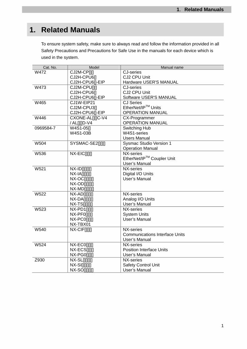
1. Related Manuals To ensure system safety, make sure to always read and follow the information provided in all Safety Precautions and Precautions for Safe Use in the manuals for each device which is used in the system. Cat. No. Model Manual name
W472 CJ2M-CP[][] CJ2H-CPU6[] CJ2H-CPU6[]-EIP
CJ-series CJ2 CPU Unit Hardware USER'S MANUAL
W473 CJ2M-CPU[][] CJ2H-CPU6[] CJ2H-CPU6[]-EIP
CJ-series CJ2 CPU Unit Software USER'S MANUAL
W465 CJ1W-EIP21 CJ2M-CPU3[] CJ2H-CPU6[]-EIP
CJ Series EtherNet/IPTM Units OPERATION MANUAL
W446 CXONE-AL[][]C-V4 / AL[][]D-V4
CX-Programmer OPERATION MANUAL
0969584-7 W4S1-05[] W4S1-03B
Switching Hub W4S1-series Users Manual
W504 SYSMAC-SE2[][][] Sysmac Studio Version 1 Operation Manual
W536 NX-EIC[][][] NX-series EtherNet/IPTM Coupler Unit User’s Manual
W521 NX-ID[][][][] NX-IA[][][][] NX-OC[][][][] NX-OD[][][][] NX-MD[][][][]
NX-series Digital I/O Units User’s Manual
W522 NX-AD[][][][] NX-DA[][][][] NX-TS[][][][]
NX-series Analog I/O Units User’s Manual
W523 NX-PD1[][][] NX-PF0[][][] NX-PC0[][][] NX-TBX01
NX-series System Units User’s Manual
W540 NX-CIF[][][] NX-series Communications Interface Units User’s Manual
W524 NX-EC0[][][] NX-ECS[][][] NX-PG0[][][]
NX-series Position Interface Units User’s Manual
Z930 NX-SL[][][][] NX-SI[][][][] NX-SO[][][][]
NX-series Safety Control Unit User’s Manual

2.Terms and Definitions
2
2. Terms and Definitions
Term Explanation and Definition Node A programmable controller and a device are connected to an EtherNet/IP
network via EtherNet/IP ports. EtherNet/IP recognizes each EtherNet/IP port connected to the network as one node. When a device with two EtherNet/IP ports is connected to the EtherNet/IP network, EtherNet/IP recognizes this device as two nodes. EtherNet/IP achieves the communications between programmable controllers or the communications between a programmable controller and a device by exchanging data between these nodes connected to the network.
Tag A minimum unit of the data that is exchanged on the EtherNet/IP network is called a tag. The tag is defined as a network variable or as a physical address, and it is assigned to the memory area of each device.
Tag set In the EtherNet/IP network, a data unit that consists of two or more tags can be exchanged. The data unit consisting of two or more tags for the data exchange is called a tag set. Up to eight tags can be configured per tag set for the programmable controllers produced by OMRON Corporation.
Tag data link In EtherNet/IP, the tag and tag set can be exchanged cyclically between nodes without using a user program. This standard feature on EtherNet/IP is called a tag data link.
Connection A connection is used to exchange data as a unit within which data concurrency is maintained. The connection consists of tags or tag sets. Creating the concurrent tag data link between the specified nodes is called a "connection establishment". When the connection is established, the tags or tag sets that configure the connection are exchanged between the specified nodes concurrently.
Connection type There are two kinds of connection types for the tag data link connection. One is a multi-cast connection, and the other is a unicast (point-to-point) connection. The multi-cast connection sends an output tag set in one packet to more than one node. The unicast connection separately sends one output tag set to each node. Therefore, multi-cast connections can decrease the communications load if one output tag set is sent to more than one node.
Originator and Target
To operate tag data links, one node requests the opening of a communications line called a "connection". The node that requests to open the connection is called an "originator", and the node that receives the request is called a "target".
Tag data link parameter
A tag data link parameter is the setting data to operate tag data links. It includes the data to set tags, tag sets, and connections.

3.Precautions
3
3. Precautions (1) Understand the specifications of devices which are used in the system. Allow some
margin for ratings and performance. Provide safety measures, such as installing a safety circuit, in order to ensure safety and minimize the risk of abnormal occurrence.
(2) To ensure system safety, make sure to always read and follow the information provided in all Safety Precautions and Precautions for Safe Use in the manuals for each device which is used in the system.
(3) The user is encouraged to confirm the standards and regulations that the system must conform to.
(4) It is prohibited to copy, to reproduce, and to distribute a part or the whole of this document without the permission of OMRON Corporation.
(5) The information contained in this document is current as of July 2016. It is subject to change for improvement without notice.
The following notations are used in this document.
Indicates a potentially hazardous situation which, if not avoided, may result in minor or moderate injury or property damage.
Precautions for Correct Use
Precautions on what to do and what not to do to ensure proper operation and performance.
Additional Information Additional information to read as required. This information is provided to increase understanding or make operation easier.
Symbol
The triangle symbol indicates precautions (including warnings). The specific operation is shown in the triangle and explained in the text. This example indicates a general precaution.
The filled circle symbol indicates operations that you must do. The specific operation is shown in the circle and explained in the text. This example shows a general precaution for something that you must do.

4.Overview
4
4. Overview This document describes the procedures for connecting NX-series EtherNet/IP Coupler Unit (hereinafter referred to as Coupler Unit) + NX-series various types of Units to CJ-series Programmable Controller + EtherNet/IP Unit (hereinafter referred to as PLC) via EtherNet/IP, both produced by OMRON Corporation (hereinafter referred to as OMRON), and for checking their communication status. In this document, the connection status is checked with an EtherNet/IP slave (hereinafter referred to as Slave Terminal) that is created by mounting I/O Units to Coupler Unit. Refer to Section 6. EtherNet/IP Settings and Section 7. EtherNet/IP Connection Procedure to understand setting methods and key points to operate EtherNet/IP tag data links. In this document, CJ-series EtherNet/IP Unit and the built-in EtherNet/IP port of CJ-series CJ2 CPU Unit are collectively called as "EtherNet/IP Unit''.

5.Applicable Devices and Device Configuration
5
5. Applicable Devices and Device Configuration
5.1. Applicable Devices The applicable devices are as follows:
Manufacturer Name Model OMRON CJ2 CPU Unit CJ2[]-CPU[][] OMRON EtherNet/IP Unit CJ1W-EIP21
CJ2H-CPU6[]-EIP CJ2M-CPU3[]
OMRON NX-series EtherNet/IPTM Coupler Unit
NX-EIC[][][]
OMRON NX-series Units DC Input Unit AC Input Unit Relay Output Unit Transistor Output Unit Digital Mixed I/O Unit Analog Input Unit Analog Output Unit Temperature Input Unit Heater Burnout Detect Unit Communications Interface Unit System Unit Load Cell Input Unit Incremental Encoder Input Unit SSI Input Unit Pulse Output Unit Safety CPU Unit Safety Input Unit Safety Output Unit
NX-ID[][][][] NX-IA[][][][] NX-OC[][][][] NX-OD[][][][] NX-MD[][][][] NX-AD[][][][] NX-DA[][][][] NX-TS[][][][] NX-HB[][][][] NX-CIF[][][] NX-PC0[][][] NX-RS[][][][] NX-EC0[][][] NX-ECS[][][] NX-PG0[][][] NX-SL[][][][] NX-SI[][][][] NX-SO[][][][]
Precautions for Correct Use
In this document, the devices with models and versions listed in 5.2. Device Configuration are used as examples of applicable devices to describe the procedures for connecting the devices and checking their connections. You cannot use devices with versions lower than the versions listed in 5.2. To use the above devices with models not listed in 5.2. or versions higher than those listed in 5.2., check the differences in the specifications by referring to the manuals before operating the devices.
Additional Information This document describes the procedures for establishing the network connections. It does not provide information on operation, installation, wiring method, device functionality, or device operation, which is not related to the connection procedures. Refer to the manuals or contact your OMRON representative.

5.Applicable Devices and Device Configuration
6
5.2. Device Configuration The hardware components to reproduce the connection procedures in this document are as follows:
Manufacturer Name Model Version OMRON CJ2 CPU Unit
(Built-in EtherNet/IP port) CJ2M-CPU32 Ver.2.0
(Ver.2.12) OMRON Power Supply Unit CJ1W-PA202 OMRON Switching hub W4S1-05C Ver.1.00 - 24 VDC power supply
(for Switching hub) -
OMRON CX-One CXONE-AL[][]C-V4 /AL[][]D-V4
Ver.4.[][]
OMRON CX-Programmer (Included in CX-One) Ver.9.60 OMRON Network Configurator (Included in CX-One) Ver.3.59a - Personal computer (OS: Windows 7) - - USB cable
(USB 2.0 type B connector) -
- LAN cable (STP (shielded, twisted-pair) cable of Ethernet category 5 or higher)
-
OMRON Coupler Unit NX-EIC202 Ver.1.0
OMRON Digital Input Unit (DC Input Unit) NX-ID4442 Ver.1.0 OMRON Digital Output Unit
(Transistor Output Unit) NX-OD3256 Ver.1.0
OMRON Analog Input Unit (Voltage Input Unit) NX-AD2603 Ver.1.0
OMRON Sysmac Studio SYSMAC-SE2[][][] Ver.1.15 - 24 VDC power supply
(Unit power supply) -
- 24 VDC power supply (I/O power supply)
-
USB cable
CJ2M-CPU32 (Built-in EtherNet/IP port)
USB cable
Personal computer (CX-One and Sysmac Studio installed, OS: Windows 7)
24 VDC power supply
LAN cable W4S1-05C
Slave Terminal NX-EIC202+ NX-ID4442+ NX-OD3256+ NX-AD2603
24 VDC power supply (Unit power supply)
24 VDC power supply (I/O power supply)
5.Applicable Devices and Device Configuration
7
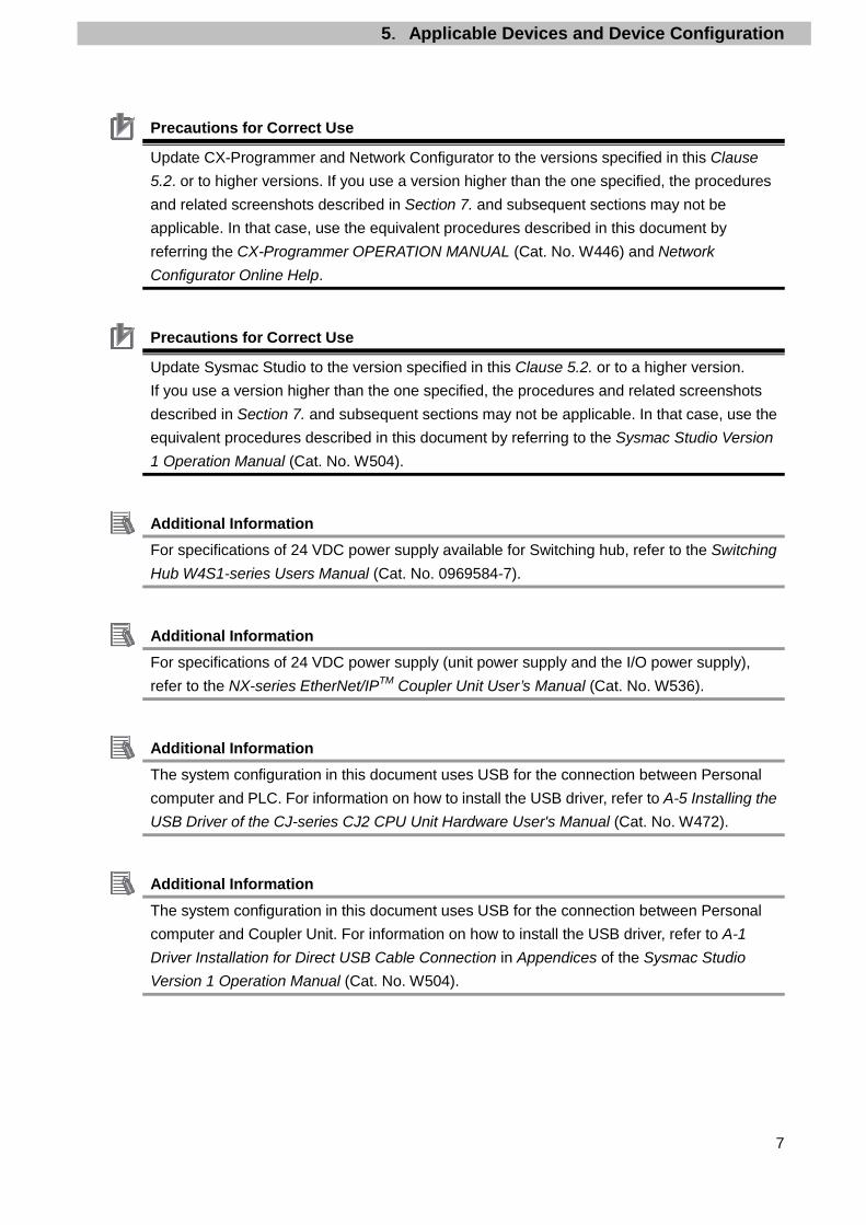
Precautions for Correct Use
Update CX-Programmer and Network Configurator to the versions specified in this Clause 5.2. or to higher versions. If you use a version higher than the one specified, the procedures and related screenshots described in Section 7. and subsequent sections may not be applicable. In that case, use the equivalent procedures described in this document by referring the CX-Programmer OPERATION MANUAL (Cat. No. W446) and Network Configurator Online Help.
Precautions for Correct Use
Update Sysmac Studio to the version specified in this Clause 5.2. or to a higher version. If you use a version higher than the one specified, the procedures and related screenshots described in Section 7. and subsequent sections may not be applicable. In that case, use the equivalent procedures described in this document by referring to the Sysmac Studio Version 1 Operation Manual (Cat. No. W504).
Additional Information For specifications of 24 VDC power supply available for Switching hub, refer to the Switching Hub W4S1-series Users Manual (Cat. No. 0969584-7).
Additional Information For specifications of 24 VDC power supply (unit power supply and the I/O power supply), refer to the NX-series EtherNet/IPTM Coupler Unit User’s Manual (Cat. No. W536).
Additional Information The system configuration in this document uses USB for the connection between Personal computer and PLC. For information on how to install the USB driver, refer to A-5 Installing the USB Driver of the CJ-series CJ2 CPU Unit Hardware User's Manual (Cat. No. W472).
Additional Information The system configuration in this document uses USB for the connection between Personal computer and Coupler Unit. For information on how to install the USB driver, refer to A-1 Driver Installation for Direct USB Cable Connection in Appendices of the Sysmac Studio Version 1 Operation Manual (Cat. No. W504).

6.EtherNet/IP Settings
8
6. EtherNet/IP Settings This section describes the contents of the parameter and tag data link settings that are all defined in this document.
6.1. Parameters The parameters required for connecting PLC to Slave Terminal via EtherNet/IP are shown below.
Item PLC (Node 1) Slave Terminal (Node 2) IP address 192.168.250.1 192.168.250.2 Subnet mask 255.255.255.0 255.255.255.0 Network interface setting - Enable tag data links
6.2. Slave Terminal Configuration The Slave Terminal configuration to use in this document is shown below. Use the configuration described here when you perform 7.2.2. Parameter Settings.
NX Unit number Model Name 0 NX-EIC202 Coupler Unit 1 NX-ID4442 Digital Input Unit 2 NX-OD3256 Digital Output Unit 3 NX-AD2603 Analog Input Unit
NX Unit number 0 1 2 3

6.EtherNet/IP Settings
9
6.3. Tag Data Link Settings The following shows the content of the tag data link settings for Slave Terminal. Output area Input area
D10000
(PLC to Slave Terminal) 2 bytes
D10100
D10103
(Slave Terminal to PLC) 8 bytes
■Output area
Address Bit Function name
D10000 0 to 3 Digital Output 0 to 3 4 to 15 -
■Input area
Address Bit Function name
D10100
0 to 3 - 4 Slave Terminal Observation 5 Slave Terminal Minor Fault 6 Slave Terminal Partial Fault 7 Slave Terminal Major Fault 8 to 13 - 14 Error Detection Flag 15 I/O Refresh Flag
D10101 0 to 7 Digital Input 0 to 7 8 to 15 -
D10102 0 to 15 Ch1 Analog Input Value D10103 0 to 15 Ch2 Analog Input Value
7.EtherNet/IP Connection Procedure
10
7. EtherNet/IP Connection Procedure This section describes the procedures for connecting PLC and Slave Terminal on the EtherNet/IP network. The explanations of procedures for setting up PLC and Slave Terminal given in this document are based on the factory default settings. For the initialization, refer to Section 8. Initialization Method.
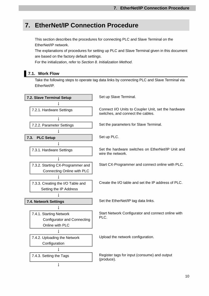
7.1. Work Flow Take the following steps to operate tag data links by connecting PLC and Slave Terminal via EtherNet/IP.
7.2. Slave Terminal Setup Set up Slave Terminal.
↓
7.2.1. Hardware Settings Connect I/O Units to Coupler Unit, set the hardware switches, and connect the cables.
↓
7.2.2. Parameter Settings Set the parameters for Slave Terminal.
↓
7.3. PLC Setup Set up PLC.
↓
7.3.1. Hardware Settings Set the hardware switches on EtherNet/IP Unit and wire the network.
↓
7.3.2. Starting CX-Programmer and Connecting Online with PLC
Start CX-Programmer and connect online with PLC.
↓
7.3.3. Creating the I/O Table and Setting the IP Address
Create the I/O table and set the IP address of PLC.
↓
7.4. Network Settings Set the EtherNet/IP tag data links.
↓
7.4.1. Starting Network Configurator and Connecting Online with PLC
Start Network Configurator and connect online with PLC.
↓
7.4.2. Uploading the Network Configuration
Upload the network configuration.
↓
7.4.3. Setting the Tags Register tags for input (consume) and output (produce).
↓
7.EtherNet/IP Connection Procedure
11
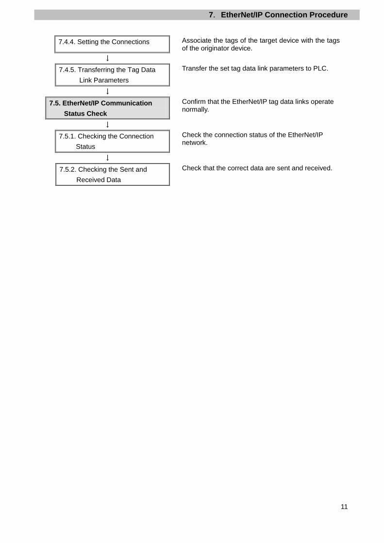
7.4.4. Setting the Connections Associate the tags of the target device with the tags of the originator device.
↓
7.4.5. Transferring the Tag Data Link Parameters
Transfer the set tag data link parameters to PLC.
↓
7.5. EtherNet/IP Communication Status Check
Confirm that the EtherNet/IP tag data links operate normally.
↓
7.5.1. Checking the Connection Status
Check the connection status of the EtherNet/IP network.
↓
7.5.2. Checking the Sent and Received Data
Check that the correct data are sent and received.
7.EtherNet/IP Connection Procedure
12
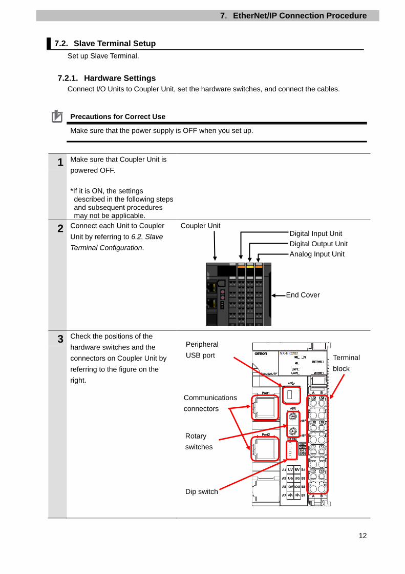
7.2. Slave Terminal Setup Set up Slave Terminal.
7.2.1. Hardware Settings Connect I/O Units to Coupler Unit, set the hardware switches, and connect the cables.
Precautions for Correct Use
Make sure that the power supply is OFF when you set up.
1 Make sure that Coupler Unit is powered OFF. *If it is ON, the settings described in the following steps and subsequent procedures may not be applicable.
2 Connect each Unit to Coupler Unit by referring to 6.2. Slave Terminal Configuration.
Coupler Unit
3 Check the positions of the hardware switches and the connectors on Coupler Unit by referring to the figure on the right.
Digital Input Unit Digital Output Unit Analog Input Unit End Cover
Communications connectors
Terminal block
Peripheral USB port
Rotary switches
Dip switch

7.EtherNet/IP Connection Procedure
13
4 Check that DIP switch is set as follows:
Pin 3 NET (Network interface setting): OFF (Enable tag data links)
Pin 4 ADR (IP address base setting): OFF (The first to third octets of the IP address is 192.168.250.)
*Set the last octet of the IP address using Rotary switches.
Pin Name Meaning Pin 1 Reserved by
the system Keep turned OFF (The factory setting is OFF) Pin 2
Pin 3 Network interface setting
ON: Enable UDP/IP communications and TCP/IP communications (disable Tag Data Links)
OFF: Enable Tag Data Links (disable UDP/IP communications and TCP/IP communications)
Pin 4 IP address base setting
ON: 192.168.1. [] (with [] set by rotary switches)
OFF:192.168.250. [] (with [] set by rotary switches)
5 Set Rotary switches as follows: ADR No.x161: 0 ADR No.x160: 2
*The IP address is set to 192.168.250.2.
6 Connect OUT0 on Digital Output Unit to IN0 on Digital Input Unit. *The I/O power supply (IOG and IOV) for Digital Input Unit and Digital Output Unit is not required to connect in the configuration described in this document owing to the short circuit of the I/O power supply (IOG and IOV) occurred within Slave Terminal.
Digital Input Unit Digital Output Unit
7 Connect Communications connector (Port 1) to Switching hub with a LAN cable.
LAN cable Switching hub Communications connectors
DC Input Unit NX-ID4442
Transistor Output Unit NX-OD3256

7.EtherNet/IP Connection Procedure
14
8 Connect Peripheral USB port to Personal computer with a USB cable.
USB cable
9 Connect 24 VDC power supply (Unit power supply) to the UV and UG terminal on Terminal block. Connect 24 VDC power supply (I/O power supply) to the IOV and IOG terminal on Terminal block.
10 Connect 24 VDC power supply (for Switching hub) to Switching hub.
24 VDC power supply (for Switching hub)
Personal computer
24 VDC power supply (Unit power supply)
+ -
24 VDC power supply (I/O power supply)
+ -

7.EtherNet/IP Connection Procedure
15
7.2.2. Parameter Settings Set the parameters for Slave Terminal. The parameters are set using Sysmac Studio. Install Sysmac Studio and the USB driver on Personal computer beforehand.
Additional Information For information on how to install Sysmac Studio and the USB driver, refer to A-1 Driver Installation for Direct USB Cable Connection in Appendices of the Sysmac Studio Version 1 Operation Manual (Cat. No. W504).
1 Turn ON Unit power supply for Slave Terminal.
2 Start Sysmac Studio. *If the User Account Control Dialog Box is displayed at start, make a selection to start Sysmac Studio.
3 Sysmac Studio starts. Click New Project.
4 The Project Properties Dialog Box is displayed. *In this document, New Project is used as the project name.
Select Slave Terminal from the pull-down list of Category.

7.EtherNet/IP Connection Procedure
16
5 Check that EtherNet/IP Coupler is selected in the Device Field. Click Create.
6 The New Project is displayed. The following panes are displayed in this window. Left: Multiview Explorer
Top right: Toolbox
Middle top: Edit Configuration Pane
The following tabs are displayed in the bottom middle of this window. Output Tab Page
Build Tab Page
7 Double-click NX-EIC202 under Configurations and Setup - EtherNet/IP in the Multiview Explorer.
Toolbox Edit
Configuration Pane Multiview
Explorer
Output Tab Page
Build Tab Page
7.EtherNet/IP Connection Procedure
17
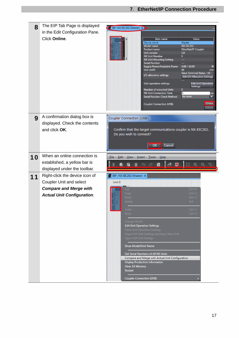
8 The EIP Tab Page is displayed in the Edit Configuration Pane. Click Online.
9 A confirmation dialog box is displayed. Check the contents and click OK.
10 When an online connection is established, a yellow bar is displayed under the toolbar.
11 Right-click the device icon of Coupler Unit and select Compare and Merge with Actual Unit Configuration.

7.EtherNet/IP Connection Procedure
18
12 The Compare and Merge with Actual Unit Configuration Dialog Box is displayed. Check that the Units are displayed in Actual Unit Configuration as shown in 6.2. Slave Terminal Configuration and that Added is shown in the Result Column.
13 Click Apply Actual Unit Configuration. Check that the each of the units is displayed in Configuration on Sysmac Studio and that Matched is displayed in the Result Column.
14 Click OK.
15 The Units are added to Coupler Unit in the EIP Tab Page as shown in 6.2. Slave Terminal Configuration.

7.EtherNet/IP Connection Procedure
19
16 Right-click the device icon of Coupler Unit and select Coupler Connection (USB) - Transfer to Coupler from the menu.
17 The Transfer to Coupler Dialog Box is displayed. Click Configuration information + Unit operation settings + Unit application data.
18 A confirmation dialog box is displayed. Check the contents and click Yes. A screen is displayed stating "Transfer to Coupler".

7.EtherNet/IP Connection Procedure
20
19 Right-click the device icon of Coupler Unit and select Coupler Connection (USB) - Compare. A dialog box is displayed stating "Compare is being executed".
20 A confirmation dialog box is displayed. Check the contents and click OK.

7.EtherNet/IP Connection Procedure
21
7.3. PLC Setup Set up PLC.
7.3.1. Hardware Settings Set the hardware switches on EtherNet/IP Unit and wire the network.
Precautions for Correct Use
Make sure that the power supply is OFF when you set up.
1 Make sure that PLC and Switching hub are powered OFF. *If either of them is ON, the settings described in the following steps and subsequent procedures may not be applicable.
2 Check the position of hardware switches on the front panel of EtherNet/IP Unit by referring to the figure on the right.
3 Set Unit number setting switch to 0.
The unit number is used to identify individual CPU Bus Units when more than one CPU Bus Unit is mounted to the same PLC. Use a small screwdriver to make the setting, taking care not to damage the rotary switch. The unit number is factory-set to 0.
4 Set Node address setting switches to the following default settings.
NODE No.x161: 0 NODE No.x160: 1
*The IP address is set to 192.168.250.1.
*By default, the first to third octets of the local IP address are fixed to 192.168.250. The fourth octet is a value that is set with Node address setting switches.
With the FINS communications service, when there are multiple EtherNet/IP Units connected to the Ethernet network, the EtherNet/IP Units are identified by node addresses. Use the node address switches to set the node address between 01 and FE hexadecimal (1 to 254 decimal).Do not set a number that has already been set for another node on the same network.
The left switch sets the sixteens digit (most significant digit) and the right switch sets the ones digit (least significant digit).The node address is factory-set to 01. Default IP address = 192.168.250.node address With the factory-default node address setting of 01, the default IP address is
192.168.250.1.

7.EtherNet/IP Connection Procedure
22
5 Connect a LAN cable to the EtherNet/IP port on PLC, and connect a USB cable to the USB port. As shown in 5.2. Device Configuration, connect Personal computer and Switching Hub to PLC.
6 Turn ON PLC and Switching hub.
7 The set IP address is displayed on the seven-segment LED indicators. Afterwards, the last digit of the IP address is displayed in hexadecimal during normal operation.
Personal computer
24 VDC power supply
LAN cable
PLC
USB cable
Power Supply Unit
Switching hub
CPU Unit

7.EtherNet/IP Connection Procedure
23
7.3.2. Starting CX-Programmer and Connecting Online with PLC Start CX-Programmer and connect online with PLC. Install CX-One and the USB driver on Personal computer beforehand.
1 Start CX-Programmer. *If the User Account Control Dialog Box is displayed at start, make a selection to start CX-Programmer.
2 CX-Programmer starts.
3 Select Auto Online - Direct Online from the PLC Menu.
4 The Direct Online Dialog Box is displayed. Select USB connection as Connection Type. Click Connect.

7.EtherNet/IP Connection Procedure
24
5 The dialog box on the right is displayed. Check the contents and click No.
6 The dialog box on the right is displayed. CX-Programmer and PLC are automatically connected.
7 Check that CX-Programmer and PLC are normally connected online.
*The icon is pressed down during online connection.
Additional Information If PLC cannot be connected online, check the cable connection. Or, return to step 1, check the settings and repeat each step. For details, refer to Connecting Directly to a CJ2 CPU Unit Using a USB Cable of the CX-Programmer OPERATION MANUAL (Cat. No. W446).
Additional Information The dialog boxes explained in the subsequent procedure may not be displayed depending on the environmental settings of CX-Programmer. For details on the environmental settings, refer to Options and Preferences in CHAPTER 3 Project Reference in PART 1: CX-Programmer of the CX-Programmer OPERATION MANUAL (Cat. No. W446). This document explains the setting procedures when ''Confirm all operations affecting the PLC'' is selected.

7.EtherNet/IP Connection Procedure
25
7.3.3. Creating the I/O Table and Setting the IP Address Create the I/O table and set the IP address of PLC.
1 If the operating mode of PLC is Run Mode or Monitor Mode, change it to Program Mode by following the steps below. (1)Select Operating Mode -
Program from the PLC Menu in CX-Programmer.
(2)The dialog box on the right is
displayed. Confirm that there is no problem, and click Yes.
*Refer to Additional Information on the previous page for the settings concerning the dialog display.
(3)Check that Stop/Program
Mode is displayed on the right of the PLC model in the Project Workspace of CX-Programmer.
(Project Workspace)
2 Select Edit - I/O Table and Unit Setup from the PLC Menu in CX-Programmer. The PLC IO Table Window is displayed.

7.EtherNet/IP Connection Procedure
26
Precautions for Correct Use
The PLC is reset after creating and transferring the I/O table in step 3 and subsequent steps. Always confirm safety before creating and transferring the I/O table.
3 Select Create from the Options Menu in the PLC IO Table Window. The dialog box on the right is displayed. Confirm that there is no problem, and click Yes. The dialog box on the right is displayed. Confirm that there is no problem, and click Yes.

7.EtherNet/IP Connection Procedure
27
4 The Transfer from PLC Dialog Box is displayed. Select IO Table and SIO Unit Parameters. Click Transfer. When the transfer is completed, the Transfer Results Dialog Box is displayed. Check that the transfer is successfully completed by referring to the message in the dialog box. When the I/O table is created normally, the dialog box displays as follows: Transfer Success: 1 Unit Transfer Unsuccessful: 0 Unit Click OK.
5 In the PLC IO Table Window, click + to the left of Built-in Port/Inner Board to display CJ2M-EIP21. *The figure on the right displays CPU Unit (Built-in EtherNet/IP port) specified in 5.2. Device Configuration. If you use an other applicable EtherNet/IP Unit, the display position and name are different from the figure on the right.
Right-click CJ2M-EIP21 and select Unit Setup.

7.EtherNet/IP Connection Procedure
28
6 The Edit Parameters Dialog Box is displayed. Select the TCP/IP Tab. Make the following settings in the IP Address Field. ・Use the following address:
Select ・IP address: 192.168.250.1 ・Subnet mask: 255.255.255.0
Click Transfer[PC to Unit].
7 The dialog box on the right is displayed. Confirm that there is no problem, and click Yes. Check that a message is displayed stating "Transfer successful". Click Close.

7.EtherNet/IP Connection Procedure
29
8 The dialog box on the right is displayed. Check the contents and click Yes. When the Unit is restarted, the dialog box on the right is displayed. Check the contents and click OK.
9 Click Compare to check that the IP address is correctly changed.
10 Check that a message is displayed stating "Compare successful". Click Close.
11 Click OK in the Edit Parameters Dialog Box.

7.EtherNet/IP Connection Procedure
30
7.4. Network Settings Set the EtherNet/IP tag data links.
7.4.1. Starting Network Configurator and Connecting Online with PLC Start Network Configurator and connect online with PLC.
1 Right-click CJ2M-EIP21 in the PLC IO Table Window, and select Start Special Application - Start with Settings Inherited. The Select Special Application Dialog Box is displayed. Select Network Configurator and click OK.
2 Network Configurator starts. The following panes are displayed in this window. Left: Hardware List
Right: Network Configuration Pane
Network Configuration Pane Hardware List
7.EtherNet/IP Connection Procedure
31
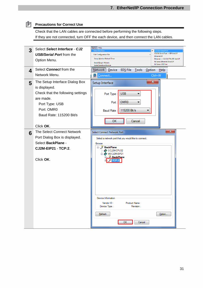
Precautions for Correct Use
Check that the LAN cables are connected before performing the following steps. If they are not connected, turn OFF the each device, and then connect the LAN cables.
3 Select Select Interface - CJ2 USB/Serial Port from the Option Menu.
4 Select Connect from the Network Menu.
5 The Setup Interface Dialog Box is displayed. Check that the following settings are made.
Port Type: USB Port: OMR0 Baud Rate: 115200 Bit/s
Click OK.
6 The Select Connect Network Port Dialog Box is displayed. Select BackPlane - CJ2M-EIP21 - TCP:2. Click OK.
7.EtherNet/IP Connection Procedure
32
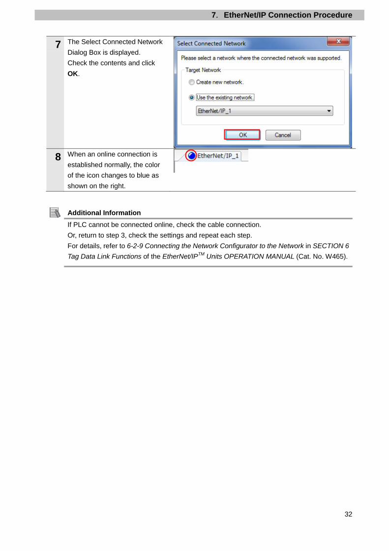
7 The Select Connected Network Dialog Box is displayed. Check the contents and click OK.
8 When an online connection is established normally, the color of the icon changes to blue as shown on the right.
Additional Information If PLC cannot be connected online, check the cable connection. Or, return to step 3, check the settings and repeat each step. For details, refer to 6-2-9 Connecting the Network Configurator to the Network in SECTION 6 Tag Data Link Functions of the EtherNet/IPTM Units OPERATION MANUAL (Cat. No. W465).

7.EtherNet/IP Connection Procedure
33
7.4.2. Uploading the Network Configuration Upload the network configuration.
1 Select Upload from the Network Menu to upload the device information on the network.
2 The dialog box on the right is displayed. Confirm that there is no problem, and click Yes.
3 The Target Device Dialog Box is displayed. Select 192.168.250.1 and 192.168.250.2. Click OK. *If 192.168.250.1 and 192.168.250.2 are not displayed in the dialog box, click Add to add the addresses.
*A displayed address depends on the status of Network Configurator.
4 The device parameters are uploaded. When the uploading is completed, the dialog box on the right is displayed. Check the contents and click OK.
7.EtherNet/IP Connection Procedure
34
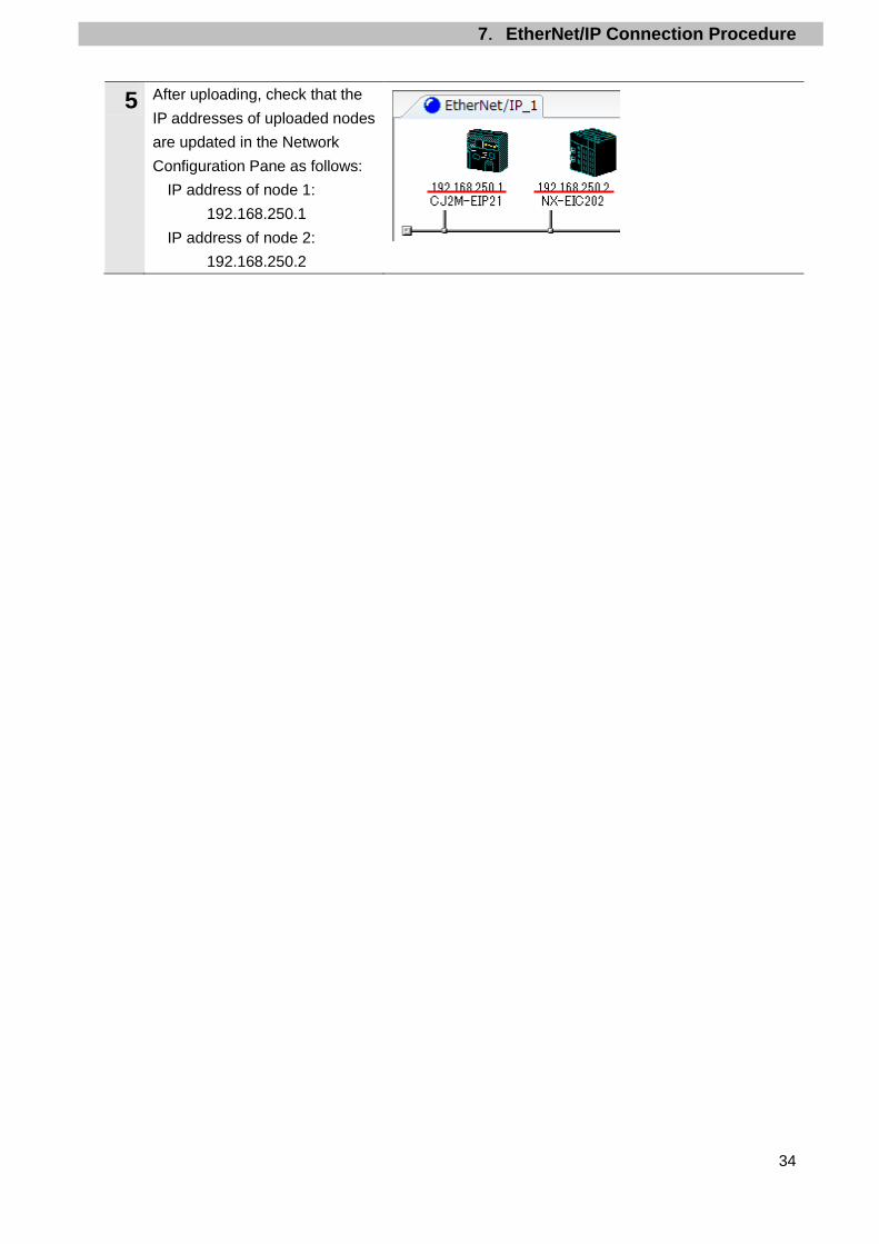
5 After uploading, check that the IP addresses of uploaded nodes are updated in the Network Configuration Pane as follows:
IP address of node 1: 192.168.250.1
IP address of node 2: 192.168.250.2

7.EtherNet/IP Connection Procedure
35
7.4.3. Setting the Tags Register tags for input (consume) and output (produce). The following explains the receive and send settings of the target device in order.
1 In the Network Configuration Pane of Network Configurator, right-click the node 1 device and select Parameter - Edit.
2 The Edit Device Parameters Dialog Box is displayed. Select the Tag Sets Tab.
3 The data on the Tag Sets Tab Page is displayed. Select the In-Consume Tab and click Edit Tags.
7.EtherNet/IP Connection Procedure
36
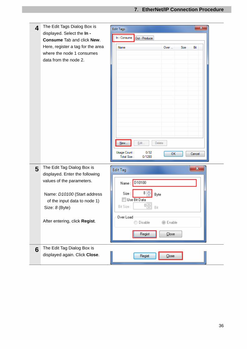
4 The Edit Tags Dialog Box is displayed. Select the In - Consume Tab and click New. Here, register a tag for the area where the node 1 consumes data from the node 2.
5 The Edit Tag Dialog Box is displayed. Enter the following values of the parameters. Name: D10100 (Start address
of the input data to node 1) Size: 8 (Byte)
After entering, click Regist.
6 The Edit Tag Dialog Box is displayed again. Click Close.
7.EtherNet/IP Connection Procedure
37
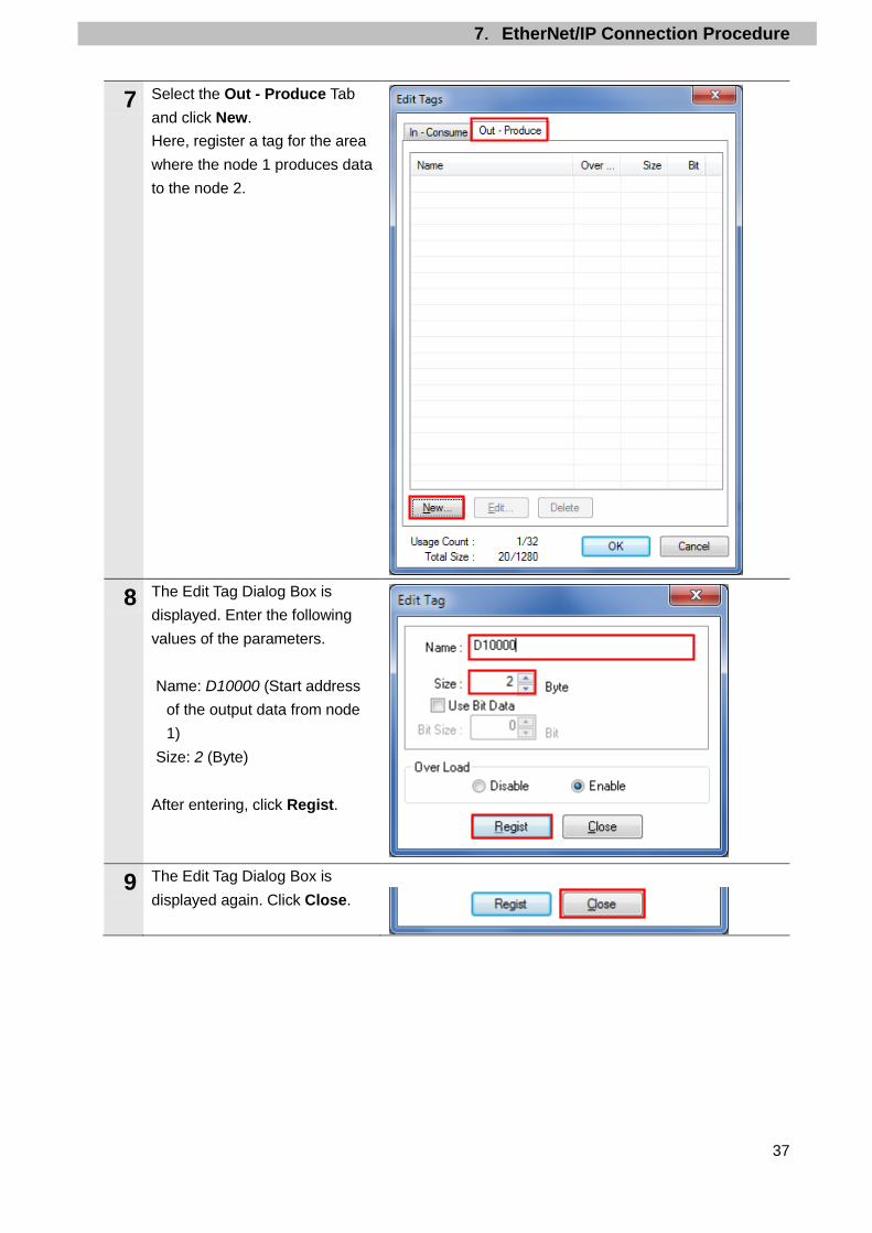
7 Select the Out - Produce Tab and click New. Here, register a tag for the area where the node 1 produces data to the node 2.
8 The Edit Tag Dialog Box is displayed. Enter the following values of the parameters. Name: D10000 (Start address
of the output data from node 1)
Size: 2 (Byte) After entering, click Regist.
9 The Edit Tag Dialog Box is displayed again. Click Close.
7.EtherNet/IP Connection Procedure
38
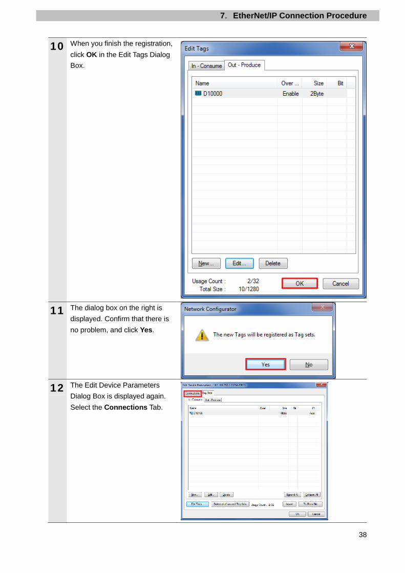
10 When you finish the registration, click OK in the Edit Tags Dialog Box.
11 The dialog box on the right is displayed. Confirm that there is no problem, and click Yes.
12 The Edit Device Parameters Dialog Box is displayed again. Select the Connections Tab.

7.EtherNet/IP Connection Procedure
39
7.4.4. Setting the Connections Associate the tags of the target device (that receives the open request) with the tags of the originator device (that requests for opening).
1 Select 192.168.250.2 in the Unregister Device List Field. Click the Down Arrow Button that is shown in the dialog box.
2 192.168.250.2 is registered in the Register Device List Field. Select 192.168.250.2 and click New.
3 The Edit Connection Dialog Box is displayed. Select Input / Output from the pull-down list of Connection I/O Type. Set the values listed in the following table in the Originator Device and the Target Device Fields.
■Connection configuration settings
Connection configuration Set value Connection I/O Type Input / Output Originator Device Input Tag Set D10100-[8 Byte]
Connection type Multi-cast connection Output Tag Set D10000-[2 Byte] Connection type Point to Point connection
Target Device Output Tag Set Input_100-[8 Byte] Input Tag Set Output_148- [2 Byte]

7.EtherNet/IP Connection Procedure
40
4 Check that the settings are correct. Click Regist.
5 The Edit Connection Dialog Box is displayed again. Click Close.
6 The Edit Device Parameters Dialog Box is displayed again. Click OK.
7 When the connection is completed, the registered node address is displayed under the device icon of node 2 in the Network Configuration Pane.
7.EtherNet/IP Connection Procedure
41
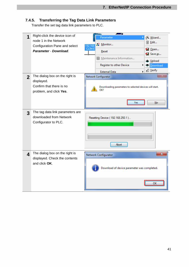
7.4.5. Transferring the Tag Data Link Parameters Transfer the set tag data link parameters to PLC.
1 Right-click the device icon of node 1 in the Network Configuration Pane and select Parameter - Download.
2 The dialog box on the right is displayed. Confirm that there is no problem, and click Yes.
3 The tag data link parameters are downloaded from Network Configurator to PLC.
4 The dialog box on the right is displayed. Check the contents and click OK.

7.EtherNet/IP Connection Procedure
42
7.5. EtherNet/IP Communication Status Check Confirm that the EtherNet/IP tag data links operate normally.
7.5.1. Checking the Connection Status Check the connection status of the EtherNet/IP network.
1 Turn ON I/O power supply for Slave Terminal.
2 Check with LED indicators on PLC (EtherNet/IP Unit) that the EtherNet/IP tag data links operate normally. The LED indicators in normal status are as follows:
MS: Green lit NS: Green lit COMM: Yellow lit 100M or 10M: Yellow lit
3 Check the LED indicators on Coupler Unit. The LED indicators in normal status are as follows:
UNIT PWR: Green lit I/O PWR: Green lit L/A P1: Green lit TS: Green lit MS: Green lit NS: Green lit
4 The normal operation of tag data links is confirmed through the status information in the Monitor Device Dialog Box of Network Configurator. Right-click the device icon of node 1 in the Network Configuration Pane and select Monitor.

7.EtherNet/IP Connection Procedure
43
5 The dialog box on the right displays the Status 1 Tab Page in the Monitor Device Dialog Box. When the same check boxes are selected as shown on the right, the tag data links are normally in operation. Click Close.
6 Select Disconnect from the Network Menu to go offline.
7 The color of the icon changes from blue to gray as shown on the right.
8 Select Exit from the File Menu to close Network Configurator.
Number: Node number Blue: Connection normal

7.EtherNet/IP Connection Procedure
44
7.5.2. Checking the Sent and Received Data Check that the correct data are sent and received.
In this procedure, the output of Slave Terminal is performed, which may have a risk of unexpected operation of Slave Terminal. Take adequate safety precautions before you proceed with this operation check described here. If you cannot ensure safety, do not proceed. When you perform this operation check, make sure to complete all the steps and make the output of Slave Terminal safe.
Ensure the safety before wiring the I/O in a state where the devices are powered OFF. Always read and follow the information provided in all safety precautions in the manuals for each device to be wired.
If the PLC memory is changed by malfunction during monitoring power flow and present value status in the Ladder Section Window or in the Watch Window, the devices connected to output units may malfunction, regardless of the operating mode of CPU Unit. Always ensure safety before monitoring power flow and present value status in the Ladder Section Window or in the Watch Window.
1 Check that the operating mode of PLC is in Stop/Program Mode. *If the PLC is not in Stop/Program Mode, change to Stop/Program Mode by referring to step 1 of 7.3.3. Creating the I/O Table and setting IP Address.
7.EtherNet/IP Connection Procedure
45
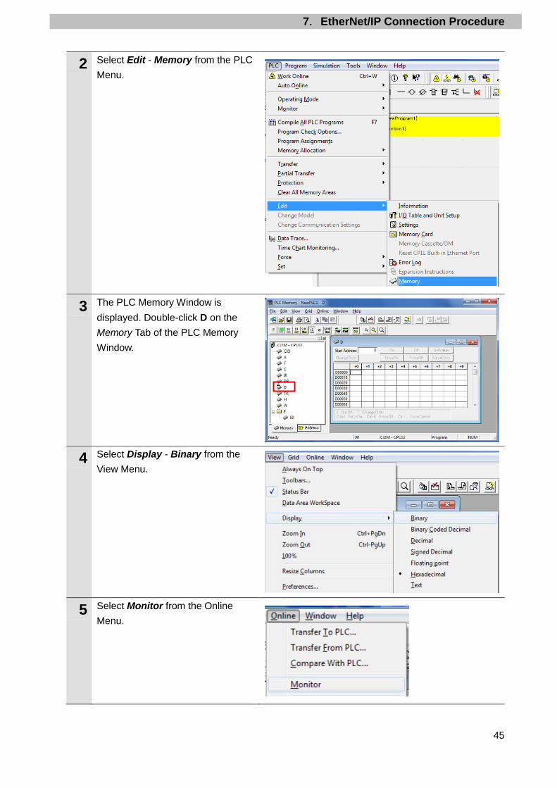
2 Select Edit - Memory from the PLC Menu.
3 The PLC Memory Window is displayed. Double-click D on the Memory Tab of the PLC Memory Window.
4 Select Display - Binary from the View Menu.
5 Select Monitor from the Online Menu.
7.EtherNet/IP Connection Procedure
46
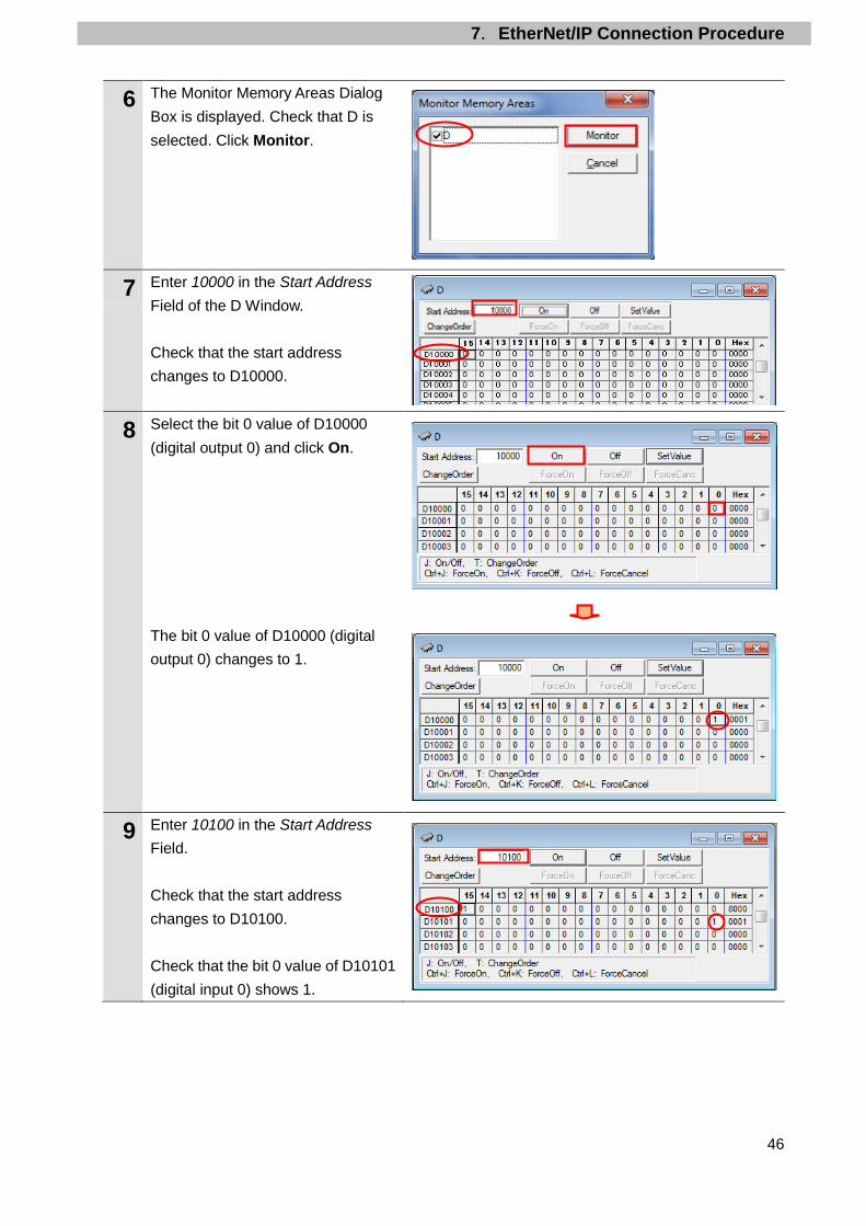
6 The Monitor Memory Areas Dialog Box is displayed. Check that D is selected. Click Monitor.
7 Enter 10000 in the Start Address Field of the D Window. Check that the start address changes to D10000.
8 Select the bit 0 value of D10000 (digital output 0) and click On. The bit 0 value of D10000 (digital output 0) changes to 1.
9 Enter 10100 in the Start Address Field. Check that the start address changes to D10100. Check that the bit 0 value of D10101 (digital input 0) shows 1.

7.EtherNet/IP Connection Procedure
47
10 Check that the LED status of Digital Input Unit and Digital Output Unit is as shown below.
Digital input 0: Lit Digital output 0: Lit
Digital Input Unit Digital Output Unit
11 Enter 10000 in the Start Address Field of the D Window. Check that the start address changes to D10000.
12 Select the bit 0 value of D10000 (digital output 0) and click Off. The bit 0 value of D10000 (digital output 0) changes to 0.
13 Enter 10100 in the Start Address Field. Check that the start address changes to D10100. Check that the bit 0 value of D10101 (digital input 0) shows 0.
14 Check that the LED status of Digital Input Unit and Digital Output Unit is as shown below.
Digital input 0: Not lit Digital output 0: Not lit
Digital Input Unit Digital Output Unit

8.Initialization Method
48
8. Initialization Method The setting procedures in this document are based on the factory default settings. Some settings may not be applicable unless you use the devices with the factory default settings.
8.1. Initializing PLC To initialize the PLC settings, it is necessary to initialize EtherNet/IP Unit and CPU Unit. Change the operating mode of PLC to PROGRAM mode before the initialization.
8.1.1. EtherNet/IP Unit To initialize the EtherNet/IP Unit settings, select Edit - I/O Table and Unit Setup from the PLC Menu in CX-Programmer, and follow the steps below.
(1)Right-click EtherNet/IP Unit in the PLC IO Table Window and select Unit Setup from the
menu.
(2)Click Restart in the Edit Parameters Dialog Box.
(3)An execution confirmation dialog box is displayed. Confirm that there is no problem, and
click Yes.

8.Initialization Method
49
(4)The Restart Unit Dialog Box is displayed. Select Return to out-of-box configuration, and then emulate cycling power, and click OK.
(5)A dialog box is displayed indicating that the execution is completed. Check the contents
and click OK.
8.1.2. CPU Unit To initialize the CPU Unit settings, select Clear All Memory Areas from the PLC Menu in CX-Programmer. Select Initialize in the Confirm All Memory Area Clear Dialog Box and click OK.
8.2. Initialization of Slave Terminal For information on how to initialize Slave Terminal, refer to 11-4 Clearing All Memory of the NX-series EtherNet/IPTM Coupler Unit User’s Manual (W536).

9.Revision History
50
9. Revision History
Revision code
Date of revision Description of revision
01 July 14, 2016 First edition

2016
0716-(-) P656-E1-01


![Ethernet Control AC Motor via PLC Using LabVIEWproprietary software, OMRON CX-Programmer over the Ethernet network [3]. With the OMRON FINS Ethernet driver in NI OPC, users can setup](https://img.dokumen.tips/doc/110x75/5e510c2cd46e535fba02fe6f/ethernet-control-ac-motor-via-plc-using-labview-proprietary-software-omron-cx-programmer.jpg)