Embed Size (px)
Citation preview
FY2015 Study for Ministry of the Environment Japan
FY 2015
Feasibility Study on Joint Crediting Mechanism Project For Realization fo a Low-Carbon Society
in Asia
Establishment of Base for Low-carbon
Project Expansion in Iskandar
(Kitakyushu-Iskandar Cooperation Project)
Report
March 2016
Kitakyushu Asian Center for Low Carbon Society NTT Data Institute of Management Consulting Institute for Global Environmental Strategies
Amita Corporation

table of contents
Chapter 1 Project Background & Objectives
1.1 Overview of Iskandar region .......................................................................... 1-1
1.2 Greenhouse gas emission reduction policies of the Malaysian Government ....................................................................................................................... 1-1
1.3 Initiatives and challenges of the Iskandar region in reducing greenhouse gas
emissions ....................................................................................................... 1-2
1.4 Cooperative relationship between the Iskandar region and Kitakyushu City ....................................................................................................................... 1-3
1.5 Project objectives and overview .................................................................... 1-4
Chapter 2 Energy Sector:The Project for Waste Heat Recovery, Cogeneration and Energy Conservation on an Industrial Estate
2.1 Objectives of the Feasibility Study and the Organizational Structure for the
Implementation of the Study .......................................................................... 2-1
2.2 Results of the Feasibility Study ..................................................................... 2-9
2.3 Investigation toward a JCM Project ............................................................... 2-27 Chapter 3 Waste Sector:“Project for Recycling Industrial Waste and Generating
Electric Power from General Waste”
3.1 Purpose and Implementing System of Project Feasibility Study................... 3-1
3.2 Results of the Project Feasibility Study ......................................................... 3-7
3.3 Investigation toward a JCM Project ............................................................... 3-41
Chapter 4 Supporting Institutional Arrangements to Develop and Replicate JCM Projects in Iskandar Malaysia
4.1 Assistance for Institutional Arrangements ..................................................... 4-1
4.2 Organising Workshops .................................................................................. 4-11
Appendix
Reference:Materials of the Second Workshop in Malaysia (Reporting Workshop)

Chapter 1
Project Background & Objectives
Chapter 1: Table of Contents 1.1 Overview of Iskandar region ................................................................................... 1-1
1.2 Greenhouse gas emission reduction policies of the Malaysian Government ........ 1-1 1.3 Initiatives and challenges of the Iskandar region in reducing greenhouse gas
emissions ................................................................................................................. 1-2 1.4 Cooperative relationship between the Iskandar region and Kitakyushu City ......... 1-3 1.5 Project objectives and overview ............................................................................. 1-4

1-1
1.1 Overview of Iskandar region
Located in the southern part of Johor State at the southern tip of the Malay Peninsula,
the Iskandar Development Region in Malaysia has a population of about 1.4 million people
and is second to only Kuala Lumpur as the largest economic metropolitan area in Malaysia.
The Iskandar region was designated as a special economic zone on July 30, 2006 where
comprehensive regional development projects have been carried out. The area of the
Iskandar region is over 2,217 km2 and includes Johor Bahru City (comprised of the towns
of Pontian, Senai, and Pasir Gudang, as well as the new administrative capital built in
Nusajaya). The entire region is divided into five flagship areas that have different roles
(central business district, educational hub, high-tech manufacturing area, etc.).
The GDP of the Iskandar region in 2005 was USD 20 billion, which accounts for 60% of
the GDP of the entire Johor State (USD 33.4 billion). The GDP per capita in Iskandar
Malaysia in 2010 was USD 10,757. It should be noted that the Iskandar region was
selected as an influential development area in the “Ninth Malaysia Plan.”
1.2 Greenhouse gas emission reduction policies of the Malaysian Government
At COP15, the Malaysian Government declared its intention to reduce CO2 emissions in
Malaysia by 2020 by 40% below 2005 levels. In order to achieve the above-mentioned
target, the “11th Malaysia Plan,” which was released in May 2015, referenced the
introduction of a framework for the promotion of a green growth strategy. The Malaysian
Government is focusing on the following four main areas in order to achieve green growth.
Focus area A: Improvement of the environment to facilitate green growth
Focus area B: Adoption of sustainable consumption and production concepts
Focus area C: Protection of natural resources for current and future generations
Focus area D: Strengthening resilience to climate change and natural disasters
1-2
1.3 Initiatives and challenges of the Iskandar region in reducing greenhouse gas emissions
An international team made up of members from Kyoto University, the National Institute
for Environmental Studies, Okayama University, Universiti Teknologi Malaysia, and the
Iskandar Regional Development Authority started activities in 2010 targeting the Iskandar
region and published the “Low Carbon Society Blueprint for Iskandar Malaysia 2025”
(hereinafter referred to as “blueprint”) in November 2012 with support from JST and JICA.
The blueprint is a plan for the development of a low-carbon society to shift the region to a
low-carbon region. The blueprint includes greenhouse gas emission reduction targets of
40% (emission intensity of 56% below 2005 levels) relative to BaU (Business as Usual)
levels by 2025 and is composed of 12 measures related to transportation systems,
construction (green building), energy systems, waste management, industrial processes,
governance, air pollution, urban structure, and education. This plan accounts for nearly
10% of the reductions that are planned for the entire country and is expected to have a
major impact on achieving national GHG emission reduction targets.
It should be noted that the Iskandar Regional Development Agency has established a
section in charge of the full-scale implementation of the blueprint within the agency and has
started the development of a detailed design that will be needed for programme
implementation.
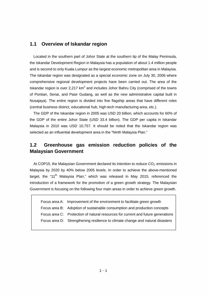
In November 2013, the “Actions for a Low Carbon Future” were formulated as tangible
measures to be taken on a priority basis. Under these actions, the “Pasir Gudang: A Green
and Healthy City” was listed as a special item, in addition to nine specific measures. As
30% of the CO2 emissions in the Iskandar Development Zone are emitted from Pasir
Gudang, the low-carbon development of the city is absolutely imperative for the steady
promotion of the LCSBP.
1-3
Figure: Plan in Pasir Gudang, Iskandar region
1.4 Cooperative relationship between the Iskandar region and Kitakyushu City
The City of Kitakyushu plans to carry out basic research and build a relationship with
Pasir Gudang to support the low-carbon development of industrial parks in the city through
the “FY 2015 Feasibility Study on the Formation of Large-scale JCM Projects to Create a
Low-carbon Society in Asia.”
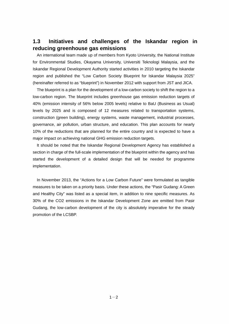
Specifically, Kitakyushu has organized consultations with related parties in Pasir Gudang
and conducted interviews with companies in industrial parks to recommend the directions
needed to achieve four key programmes under the “Pasir Gudang: Green and Healthy City”
plan.
1-4
Figure: Directions to achieve the four key programmes in Pasir Gudang
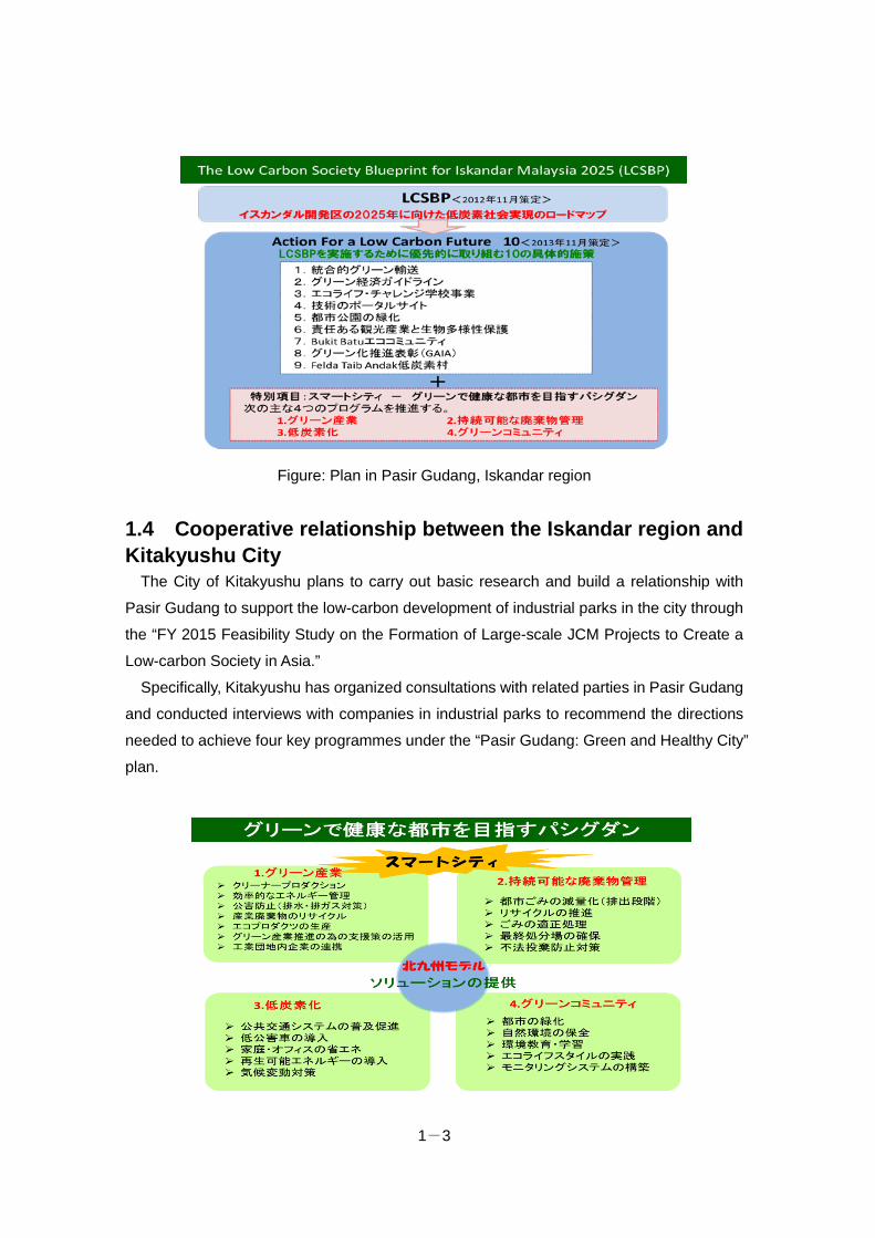
1.5 Project objectives and overview Based on the outcomes of a survey conducted in the last fiscal year, Kitakyushu, which
possesses the know-how for developing a low-carbon society, aims to create systems,
including the operation of local systems, in sectors that have the best potential for CO2
emission reductions at the energy source, such as the energy and waste sectors, in
cooperation with the Iskandar Malaysia region in order to implement activities to promote
the full expansion of Japanese technologies, with the aim of acquiring JCM credit.
Figure: Overview of all projects
Chapter 2
The Energy Sector:
The Project for Waste Heat Recovery, Cogeneration and
Energy Conservation on an Industrial Estate
NTT DATA Institute of Management Consulting, Inc.
Chapter 2 Contents 2.1 The Objectives of the Feasibility Study and the Organizational Structure for the
Implementation of the Study ............................................................................ 2-1 2.2 The Results of the Feasibility Study................................................................. 2-9 2.3 Investigation toward a JCM Project ................................................................. 2-27

2-1
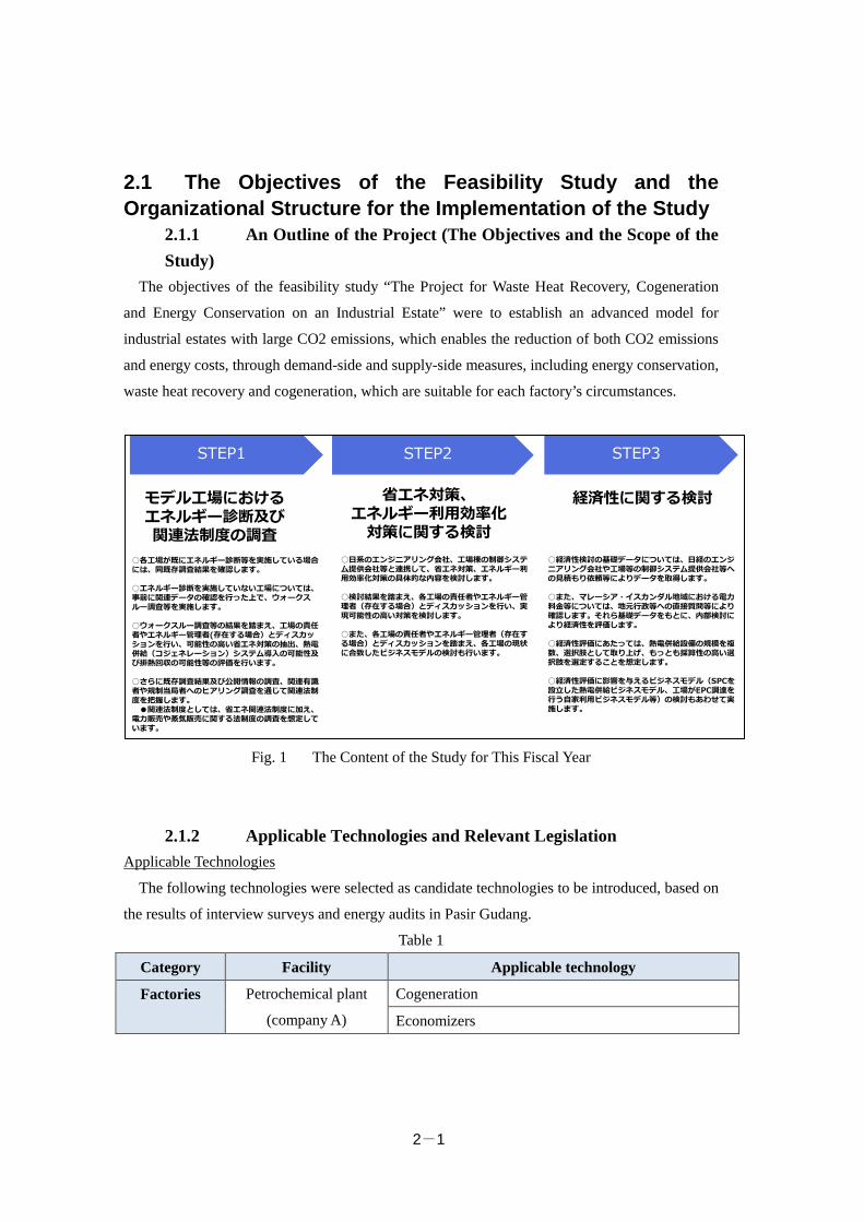
2.1 The Objectives of the Feasibility Study and the Organizational Structure for the Implementation of the Study
2.1.1 An Outline of the Project (The Objectives and the Scope of the Study)
The objectives of the feasibility study “The Project for Waste Heat Recovery, Cogeneration
and Energy Conservation on an Industrial Estate” were to establish an advanced model for
industrial estates with large CO2 emissions, which enables the reduction of both CO2 emissions
and energy costs, through demand-side and supply-side measures, including energy conservation,
waste heat recovery and cogeneration, which are suitable for each factory’s circumstances.
Fig. 1 The Content of the Study for This Fiscal Year
2.1.2 Applicable Technologies and Relevant Legislation Applicable Technologies
The following technologies were selected as candidate technologies to be introduced, based on
the results of interview surveys and energy audits in Pasir Gudang.
Table 1
Category Facility Applicable technology
Factories Petrochemical plant
(company A)
Cogeneration
Economizers
STEP2 STEP3
モデル工場におけるエネルギー診断及び関連法制度の調査
省エネ対策、エネルギー利用効率化対策に関する検討
経済性に関する検討
STEP1
○各工場が既にエネルギー診断等を実施している場合には、同既存調査結果を確認します。
○エネルギー診断を実施していない工場については、事前に関連データの確認を行った上で、ウォークスルー調査等を実施します。
○ウォークスルー調査等の結果を踏まえ、工場の責任者やエネルギー管理者(存在する場合)とディスカッションを行い、可能性の高い省エネ対策の抽出、熱電併給(コジェネレーション)システム導入の可能性及び排熱回収の可能性等の評価を行います。
○さらに既存調査結果及び公開情報の調査、関連有識者や規制当局者へのヒアリング調査を通じて関連法制度を把握します。●関連法制度としては、省エネ関連法制度に加え、
電力販売や蒸気販売に関する法制度の調査を想定しています。
○日系のエンジニアリング会社、工場棟の制御システム提供会社等と連携して、省エネ対策、エネルギー利用効率化対策の具体的な内容を検討します。
○検討結果を踏まえ、各工場の責任者やエネルギー管理者(存在する場合)とディスカッションを行い、実現可能性の高い対策を検討します。
○また、各工場の責任者やエネルギー管理者(存在する場合)とディスカッションを踏まえ、各工場の現状に合致したビジネスモデルの検討も行います。
○経済性検討の基礎データについては、日経のエンジニアリング会社や工場等の制御システム提供会社等への見積もり依頼等によりデータを取得します。
○また、マレーシア・イスカンダル地域における電力料金等については、地元行政等への直接質問等により確認します。それら基礎データをもとに、内部検討により経済性を評価します。
○経済性評価にあたっては、熱電併給設備の規模を複数、選択肢として取り上げ、もっとも採算性の高い選択肢を選定することを想定します。
○経済性評価に影響を与えるビジネスモデル(SPCを設立した熱電併給ビジネスモデル、工場がEPC調達を行う自家利用ビジネスモデル等)の検討もあわせて実施します。
2-2
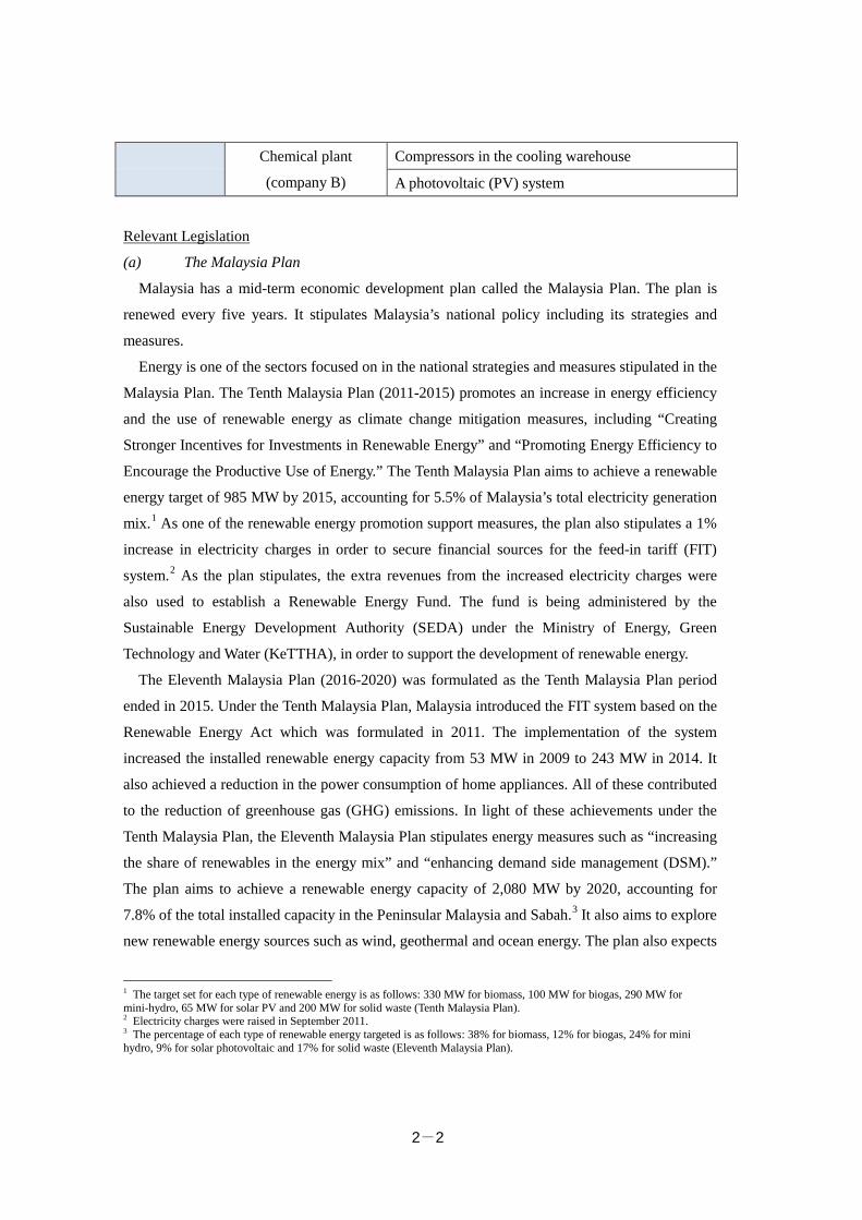
Chemical plant
(company B)
Compressors in the cooling warehouse
A photovoltaic (PV) system
Relevant Legislation
(a) The Malaysia Plan
Malaysia has a mid-term economic development plan called the Malaysia Plan. The plan is
renewed every five years. It stipulates Malaysia’s national policy including its strategies and
measures.
Energy is one of the sectors focused on in the national strategies and measures stipulated in the
Malaysia Plan. The Tenth Malaysia Plan (2011-2015) promotes an increase in energy efficiency
and the use of renewable energy as climate change mitigation measures, including “Creating
Stronger Incentives for Investments in Renewable Energy” and “Promoting Energy Efficiency to
Encourage the Productive Use of Energy.” The Tenth Malaysia Plan aims to achieve a renewable
energy target of 985 MW by 2015, accounting for 5.5% of Malaysia’s total electricity generation
mix.1 As one of the renewable energy promotion support measures, the plan also stipulates a 1%
increase in electricity charges in order to secure financial sources for the feed-in tariff (FIT)
system.2 As the plan stipulates, the extra revenues from the increased electricity charges were
also used to establish a Renewable Energy Fund. The fund is being administered by the
Sustainable Energy Development Authority (SEDA) under the Ministry of Energy, Green
Technology and Water (KeTTHA), in order to support the development of renewable energy.
The Eleventh Malaysia Plan (2016-2020) was formulated as the Tenth Malaysia Plan period
ended in 2015. Under the Tenth Malaysia Plan, Malaysia introduced the FIT system based on the
Renewable Energy Act which was formulated in 2011. The implementation of the system
increased the installed renewable energy capacity from 53 MW in 2009 to 243 MW in 2014. It
also achieved a reduction in the power consumption of home appliances. All of these contributed
to the reduction of greenhouse gas (GHG) emissions. In light of these achievements under the
Tenth Malaysia Plan, the Eleventh Malaysia Plan stipulates energy measures such as “increasing
the share of renewables in the energy mix” and “enhancing demand side management (DSM).”
The plan aims to achieve a renewable energy capacity of 2,080 MW by 2020, accounting for
7.8% of the total installed capacity in the Peninsular Malaysia and Sabah.3 It also aims to explore
new renewable energy sources such as wind, geothermal and ocean energy. The plan also expects
1 The target set for each type of renewable energy is as follows: 330 MW for biomass, 100 MW for biogas, 290 MW for mini-hydro, 65 MW for solar PV and 200 MW for solid waste (Tenth Malaysia Plan). 2 Electricity charges were raised in September 2011. 3 The percentage of each type of renewable energy targeted is as follows: 38% for biomass, 12% for biogas, 24% for mini hydro, 9% for solar photovoltaic and 17% for solid waste (Eleventh Malaysia Plan).
2-3
that the exploration of renewable energy sources and efforts to increase renewable energy
capacity will contribute to creating employment and enhance skills in the renewable energy
industry. The plan also states that energy efficiency and strategic resource conservation will be
enhanced through the implementation of net energy metering which aims to encourage more
renewable energy generation as well as through DSM which aims to encourage consumers to use
less energy during peak hours and to move energy use to off-peak hours.
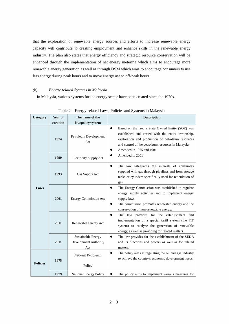
(b) Energy-related Systems in Malaysia
In Malaysia, various systems for the energy sector have been created since the 1970s.
Table 2 Energy-related Laws, Policies and Systems in Malaysia Category Year of
creation The name of the
law/policy/system Description
Laws
1974 Petroleum Development
Act
Based on the law, a State Owned Entity (SOE) was established and vested with the entire ownership, exploration and production of petroleum resources and control of the petroleum resources in Malaysia.
Amended in 1975 and 1981
1990 Electricity Supply Act Amended in 2001
1993 Gas Supply Act
The law safeguards the interests of consumers supplied with gas through pipelines and from storage tanks or cylinders specifically used for reticulation of gas.
2001 Energy Commission Act
The Energy Commission was established to regulate energy supply activities and to implement energy supply laws.
The commission promotes renewable energy and the conservation of non-renewable energy.
2011 Renewable Energy Act
The law provides for the establishment and implementation of a special tariff system (the FIT system) to catalyze the generation of renewable energy, as well as providing for related matters.
2011 Sustainable Energy
Development Authority Act
The law provides for the establishment of the SEDA and its functions and powers as well as for related matters.
Policies 1975
National Petroleum
Policy
The policy aims at regulating the oil and gas industry to achieve the country's economic development needs.
1979 National Energy Policy The policy aims to implement various measures for
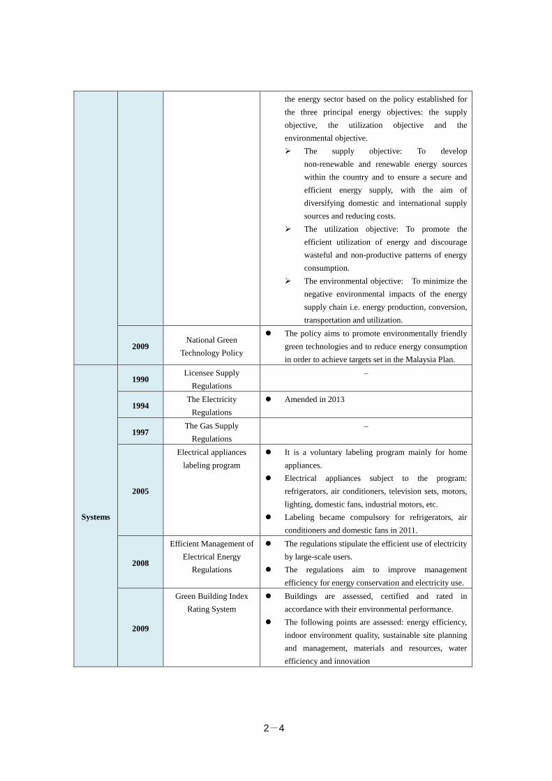
2-4
the energy sector based on the policy established for the three principal energy objectives: the supply objective, the utilization objective and the environmental objective. The supply objective: To develop
non-renewable and renewable energy sources within the country and to ensure a secure and efficient energy supply, with the aim of diversifying domestic and international supply sources and reducing costs.
The utilization objective: To promote the efficient utilization of energy and discourage wasteful and non-productive patterns of energy consumption.
The environmental objective: To minimize the negative environmental impacts of the energy supply chain i.e. energy production, conversion, transportation and utilization.
2009 National Green
Technology Policy
The policy aims to promote environmentally friendly green technologies and to reduce energy consumption in order to achieve targets set in the Malaysia Plan.
Systems
1990 Licensee Supply
Regulations –
1994 The Electricity
Regulations Amended in 2013
1997 The Gas Supply
Regulations –
2005
Electrical appliances labeling program
It is a voluntary labeling program mainly for home appliances.
Electrical appliances subject to the program: refrigerators, air conditioners, television sets, motors, lighting, domestic fans, industrial motors, etc.
Labeling became compulsory for refrigerators, air conditioners and domestic fans in 2011.
2008
Efficient Management of Electrical Energy
Regulations
The regulations stipulate the efficient use of electricity by large-scale users.
The regulations aim to improve management efficiency for energy conservation and electricity use.
2009
Green Building Index Rating System
Buildings are assessed, certified and rated in accordance with their environmental performance.
The following points are assessed: energy efficiency, indoor environment quality, sustainable site planning and management, materials and resources, water efficiency and innovation
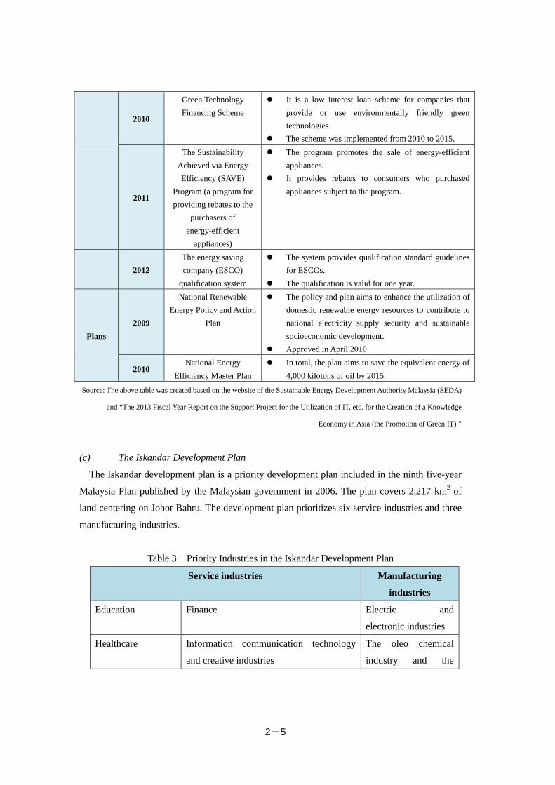
2-5
2010
Green Technology Financing Scheme
It is a low interest loan scheme for companies that provide or use environmentally friendly green technologies.
The scheme was implemented from 2010 to 2015.
2011
The Sustainability Achieved via Energy Efficiency (SAVE)
Program (a program for providing rebates to the
purchasers of energy-efficient
appliances)
The program promotes the sale of energy-efficient appliances.
It provides rebates to consumers who purchased appliances subject to the program.
2012
The energy saving company (ESCO)
qualification system
The system provides qualification standard guidelines for ESCOs.
The qualification is valid for one year.
Plans 2009
National Renewable Energy Policy and Action
Plan
The policy and plan aims to enhance the utilization of domestic renewable energy resources to contribute to national electricity supply security and sustainable socioeconomic development.
Approved in April 2010
2010 National Energy
Efficiency Master Plan In total, the plan aims to save the equivalent energy of
4,000 kilotons of oil by 2015.
Source: The above table was created based on the website of the Sustainable Energy Development Authority Malaysia (SEDA)
and “The 2013 Fiscal Year Report on the Support Project for the Utilization of IT, etc. for the Creation of a Knowledge
Economy in Asia (the Promotion of Green IT).”
(c) The Iskandar Development Plan
The Iskandar development plan is a priority development plan included in the ninth five-year
Malaysia Plan published by the Malaysian government in 2006. The plan covers 2,217 km2 of
land centering on Johor Bahru. The development plan prioritizes six service industries and three
manufacturing industries.
Table 3 Priority Industries in the Iskandar Development Plan
Service industries Manufacturing
industries
Education Finance Electric and
electronic industries
Healthcare Information communication technology
and creative industries
The oleo chemical
industry and the
2-6
petrochemical
industry
Logistics Tourism Food and agricultural
processing
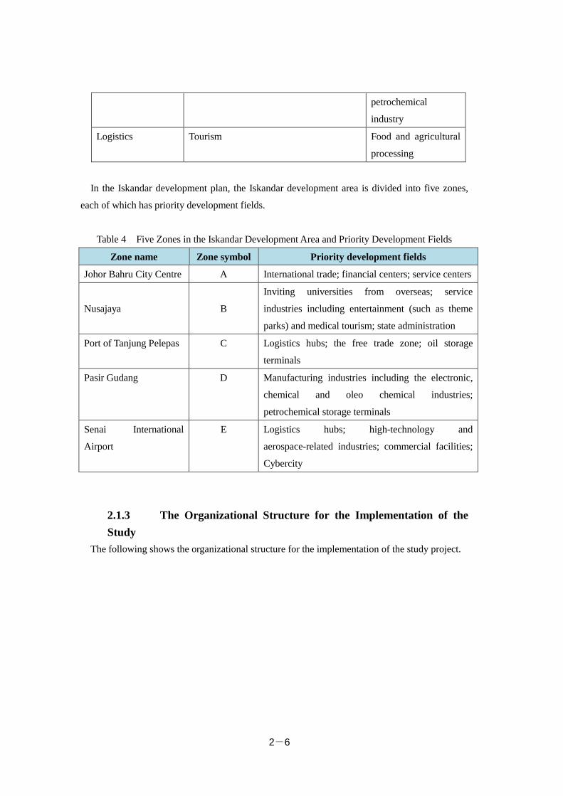
In the Iskandar development plan, the Iskandar development area is divided into five zones,
each of which has priority development fields.
Table 4 Five Zones in the Iskandar Development Area and Priority Development Fields
Zone name Zone symbol Priority development fields
Johor Bahru City Centre A International trade; financial centers; service centers
Nusajaya
B
Inviting universities from overseas; service
industries including entertainment (such as theme
parks) and medical tourism; state administration
Port of Tanjung Pelepas C Logistics hubs; the free trade zone; oil storage
terminals
Pasir Gudang D Manufacturing industries including the electronic,
chemical and oleo chemical industries;
petrochemical storage terminals
Senai International
Airport
E Logistics hubs; high-technology and
aerospace-related industries; commercial facilities;
Cybercity
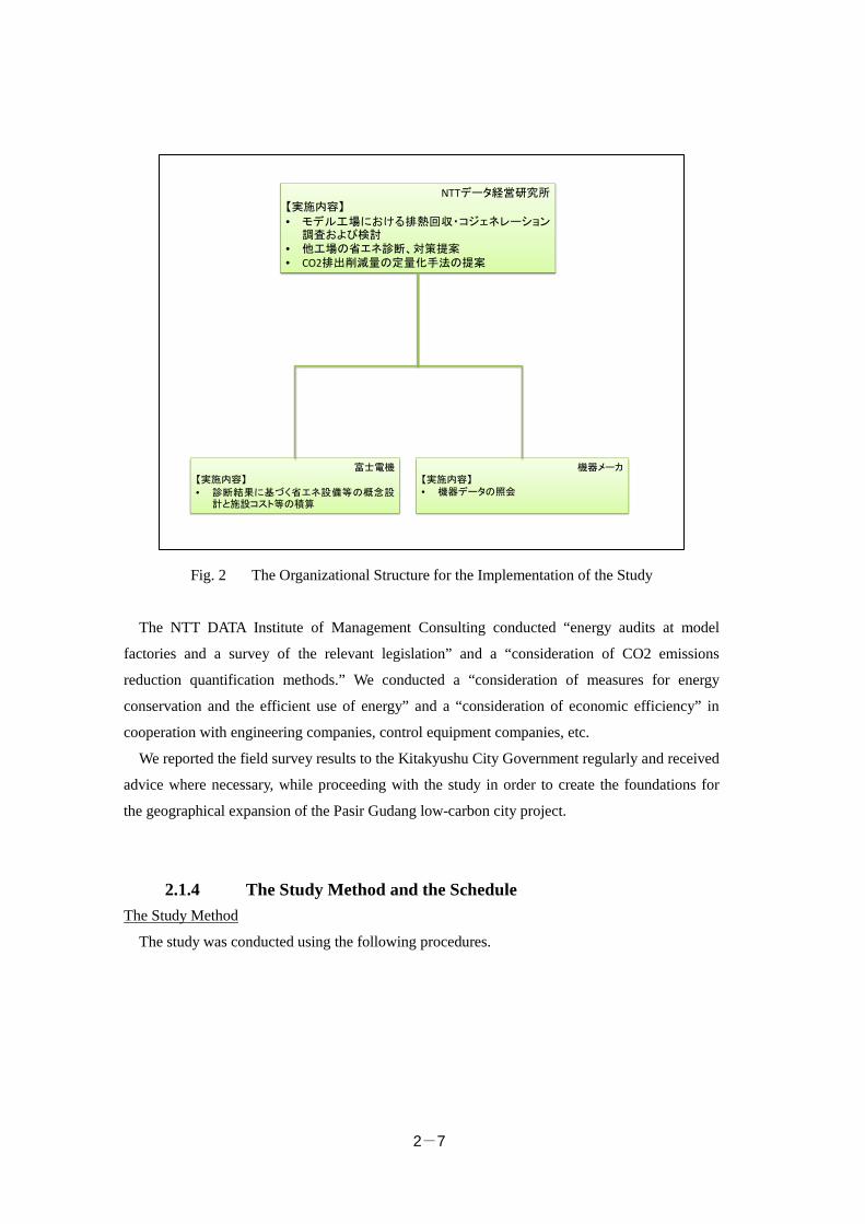
2.1.3 The Organizational Structure for the Implementation of the Study
The following shows the organizational structure for the implementation of the study project.
2-7
Fig. 2 The Organizational Structure for the Implementation of the Study
The NTT DATA Institute of Management Consulting conducted “energy audits at model
factories and a survey of the relevant legislation” and a “consideration of CO2 emissions
reduction quantification methods.” We conducted a “consideration of measures for energy
conservation and the efficient use of energy” and a “consideration of economic efficiency” in
cooperation with engineering companies, control equipment companies, etc.
We reported the field survey results to the Kitakyushu City Government regularly and received
advice where necessary, while proceeding with the study in order to create the foundations for
the geographical expansion of the Pasir Gudang low-carbon city project.
2.1.4 The Study Method and the Schedule The Study Method
The study was conducted using the following procedures.
NTTデータ経営研究所【実施内容】
• モデル工場における排熱回収・コジェネレーション調査および検討
• 他工場の省エネ診断、対策提案• CO2排出削減量の定量化手法の提案
機器メーカ【実施内容】• 機器データの照会
富士電機【実施内容】
• 診断結果に基づく省エネ設備等の概念設計と施設コスト等の積算
2-8
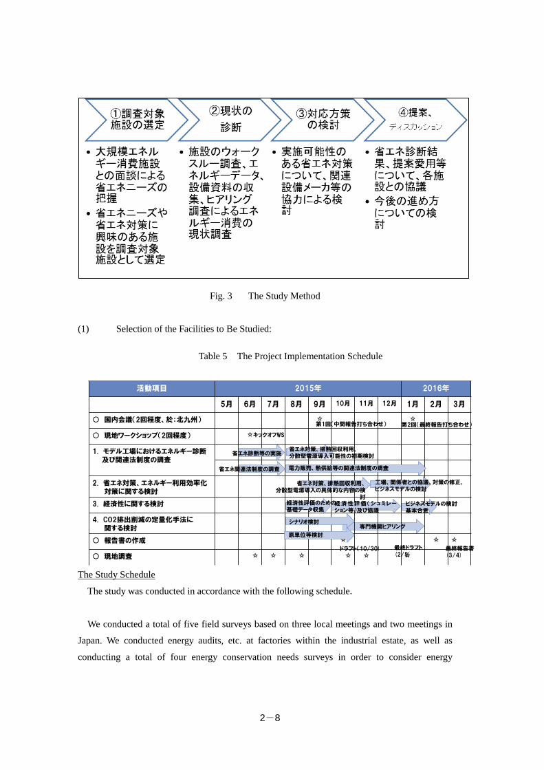
Fig. 3 The Study Method
(1) Selection of the Facilities to Be Studied:
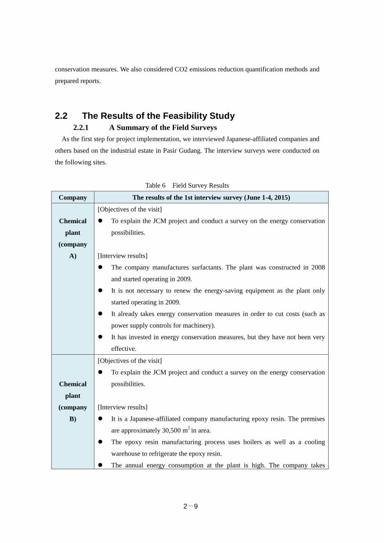
The Study Schedule
The study was conducted in accordance with the following schedule.
We conducted a total of five field surveys based on three local meetings and two meetings in
Japan. We conducted energy audits, etc. at factories within the industrial estate, as well as
conducting a total of four energy conservation needs surveys in order to consider energy
活動項目 2015年 2016年
5月 6月 7月 8月 9月 10月 11月 12月 1月 2月 3月
○ 国内会議(2回程度、於:北九州) ☆ ☆
○ 現地ワークショップ(2回程度) ☆
1. モデル工場におけるエネルギー診断及び関連法制度の調査
2. 省エネ対策、エネルギー利用効率化対策に関する検討
3. 経済性に関する検討
4. CO2排出削減の定量化手法に関する検討
○ 報告書の作成 ☆ ☆ ☆
○ 現地調査 ☆ ☆ ☆ ☆ ☆ ☆
省エネ診断等の実施
省エネ関連法制度の調査
省エネ対策、排熱回収利用、分散型電源導入の具体的な内容の検
討
工場、関係者との協議、対策の修正、ビジネスモデルの検討
第1回(中間報告打ち合わせ) 第2回(最終報告打ち合わせ)
キックオフWS
経済性評価のための基礎データ収集
経済性評価(シュミレーション等)及び協議
ビジネスモデルの検討基本合意
ドラフト(10/30) 最終ドラフト(2/5)
最終報告書(3/4)
原単位等検討
省エネ対策、排熱回収利用、分散型電源導入可能性の初期検討
電力販売、熱供給等の関連法制度の調査
専門機関ヒアリングシナリオ検討
Table 5 The Project Implementation Schedule
2-9
conservation measures. We also considered CO2 emissions reduction quantification methods and
prepared reports.
2.2 The Results of the Feasibility Study 2.2.1 A Summary of the Field Surveys
As the first step for project implementation, we interviewed Japanese-affiliated companies and
others based on the industrial estate in Pasir Gudang. The interview surveys were conducted on
the following sites.
Table 6 Field Survey Results
Company The results of the 1st interview survey (June 1-4, 2015)
Chemical
plant
(company
A)
[Objectives of the visit]
To explain the JCM project and conduct a survey on the energy conservation
possibilities.
[Interview results]
The company manufactures surfactants. The plant was constructed in 2008
and started operating in 2009.
It is not necessary to renew the energy-saving equipment as the plant only
started operating in 2009.
It already takes energy conservation measures in order to cut costs (such as
power supply controls for machinery).
It has invested in energy conservation measures, but they have not been very
effective.
Chemical
plant
(company
B)
[Objectives of the visit]
To explain the JCM project and conduct a survey on the energy conservation
possibilities.
[Interview results]
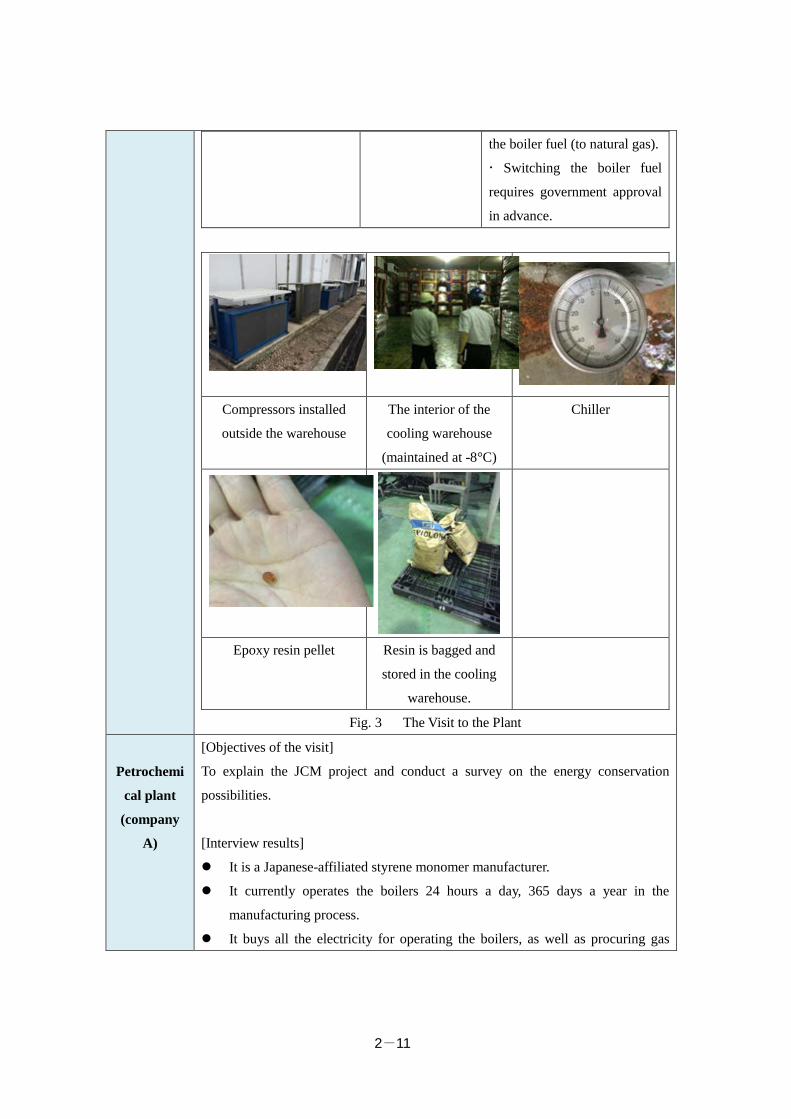
It is a Japanese-affiliated company manufacturing epoxy resin. The premises
are approximately 30,500 m2 in area.
The epoxy resin manufacturing process uses boilers as well as a cooling
warehouse to refrigerate the epoxy resin.
The annual energy consumption at the plant is high. The company takes
2-10
energy conservation measures in its daily business activities, for example,
turning off the lights and air conditioners in the offices wherever possible.
However, if the company renews equipment, etc., it is expected to achieve a
more significant CO2 emissions reduction.
Table 6 Potential Equipment to Be Renewed/Introduced at the Chemical Plant
(Company B) through the Project
Potential equipment to
be renewed/introduced
Expected effects Project possibilities
The introduction of a PV
system on the roof of the
cooling warehouse
Heat-blocking
effect
CO2 emissions
reduction through
the replacement of
power from the
grid
The company wants to
consider installing a PV
system as it has a large
warehouse roof.
Replacement of lightings
in the cooling warehouse
with LED lights
Further energy
conservation in the
cooling warehouse
The energy conservation
effects are expected to be
small as it uses a small
number of lights.
Renewal of compressors
in the cooling warehouse
Further energy
conservation in the
cooling warehouse
The company considers the
high cost of renewing all the
cooling equipment (14 units in
total) in the cooling warehouse
to be a problem.
There is a high possibility of
a project taking place, as five
compressors have to be
renewed relatively soon.
Switching the boiler fuel
from diesel oil to natural
gas
CO2 emissions
reduction through
switching the fuel
The company has two boilers
and one of them is in
operation 24 hours a day, 365
days a year.
It is considering switching
2-11
the boiler fuel (to natural gas).
Switching the boiler fuel
requires government approval
in advance.
Compressors installed
outside the warehouse
The interior of the
cooling warehouse
(maintained at -8°C)
Chiller
Epoxy resin pellet Resin is bagged and
stored in the cooling
warehouse.
Fig. 3 The Visit to the Plant
Petrochemi
cal plant
(company
A)
[Objectives of the visit]
To explain the JCM project and conduct a survey on the energy conservation
possibilities.
[Interview results]
It is a Japanese-affiliated styrene monomer manufacturer.
It currently operates the boilers 24 hours a day, 365 days a year in the
manufacturing process.
It buys all the electricity for operating the boilers, as well as procuring gas
2-12
(natural gas) from outside the plant.
It had considered the introduction of cogeneration and economizers in the
past.
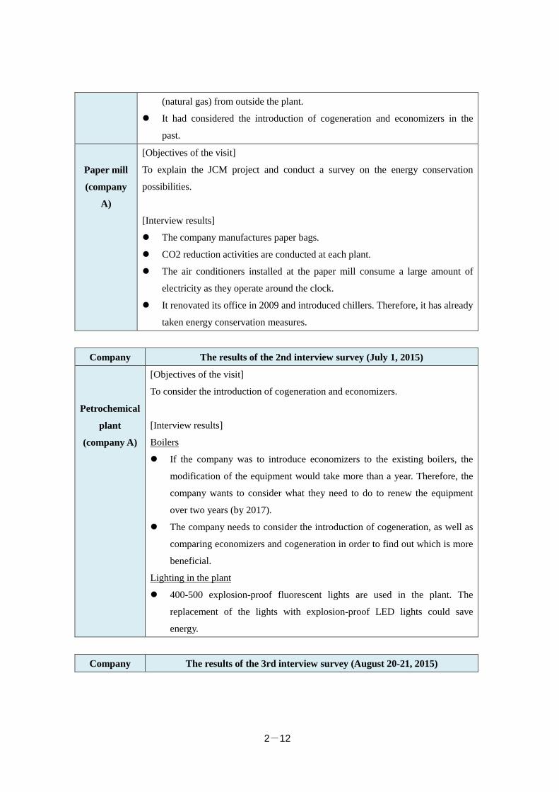
Paper mill
(company
A)
[Objectives of the visit]
To explain the JCM project and conduct a survey on the energy conservation
possibilities.
[Interview results]
The company manufactures paper bags.
CO2 reduction activities are conducted at each plant.
The air conditioners installed at the paper mill consume a large amount of
electricity as they operate around the clock.
It renovated its office in 2009 and introduced chillers. Therefore, it has already
taken energy conservation measures.
Company The results of the 2nd interview survey (July 1, 2015)
Petrochemical
plant
(company A)
[Objectives of the visit]
To consider the introduction of cogeneration and economizers.
[Interview results]
Boilers
If the company was to introduce economizers to the existing boilers, the
modification of the equipment would take more than a year. Therefore, the
company wants to consider what they need to do to renew the equipment
over two years (by 2017). The company needs to consider the introduction of cogeneration, as well as
comparing economizers and cogeneration in order to find out which is more
beneficial.
Lighting in the plant
400-500 explosion-proof fluorescent lights are used in the plant. The
replacement of the lights with explosion-proof LED lights could save
energy.
Company The results of the 3rd interview survey (August 20-21, 2015)
2-13
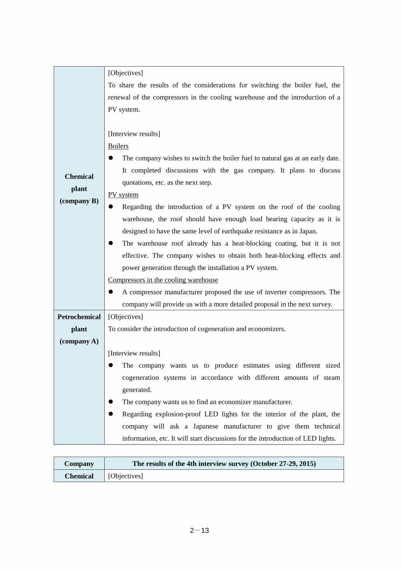
Chemical
plant
(company B)
[Objectives]
To share the results of the considerations for switching the boiler fuel, the
renewal of the compressors in the cooling warehouse and the introduction of a
PV system.
[Interview results]
Boilers
The company wishes to switch the boiler fuel to natural gas at an early date.
It completed discussions with the gas company. It plans to discuss
quotations, etc. as the next step.
PV system
Regarding the introduction of a PV system on the roof of the cooling
warehouse, the roof should have enough load bearing capacity as it is
designed to have the same level of earthquake resistance as in Japan.
The warehouse roof already has a heat-blocking coating, but it is not
effective. The company wishes to obtain both heat-blocking effects and
power generation through the installation a PV system.
Compressors in the cooling warehouse
A compressor manufacturer proposed the use of inverter compressors. The
company will provide us with a more detailed proposal in the next survey.
Petrochemical
plant
(company A)
[Objectives]
To consider the introduction of cogeneration and economizers.
[Interview results]
The company wants us to produce estimates using different sized
cogeneration systems in accordance with different amounts of steam
generated.
The company wants us to find an economizer manufacturer.
Regarding explosion-proof LED lights for the interior of the plant, the
company will ask a Japanese manufacturer to give them technical
information, etc. It will start discussions for the introduction of LED lights.
Company The results of the 4th interview survey (October 27-29, 2015)
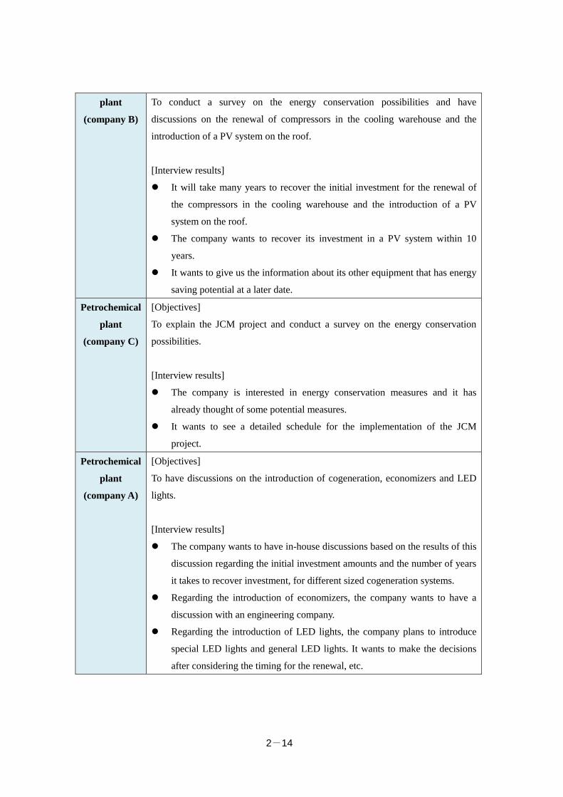
Chemical [Objectives]
2-14
plant
(company B)
To conduct a survey on the energy conservation possibilities and have
discussions on the renewal of compressors in the cooling warehouse and the
introduction of a PV system on the roof.
[Interview results]
It will take many years to recover the initial investment for the renewal of
the compressors in the cooling warehouse and the introduction of a PV
system on the roof.
The company wants to recover its investment in a PV system within 10
years.
It wants to give us the information about its other equipment that has energy
saving potential at a later date.
Petrochemical
plant
(company C)
[Objectives]
To explain the JCM project and conduct a survey on the energy conservation
possibilities.
[Interview results]
The company is interested in energy conservation measures and it has
already thought of some potential measures.
It wants to see a detailed schedule for the implementation of the JCM
project.
Petrochemical
plant
(company A)
[Objectives]
To have discussions on the introduction of cogeneration, economizers and LED
lights.
[Interview results]
The company wants to have in-house discussions based on the results of this
discussion regarding the initial investment amounts and the number of years
it takes to recover investment, for different sized cogeneration systems.
Regarding the introduction of economizers, the company wants to have a
discussion with an engineering company.
Regarding the introduction of LED lights, the company plans to introduce
special LED lights and general LED lights. It wants to make the decisions
after considering the timing for the renewal, etc.
2-15
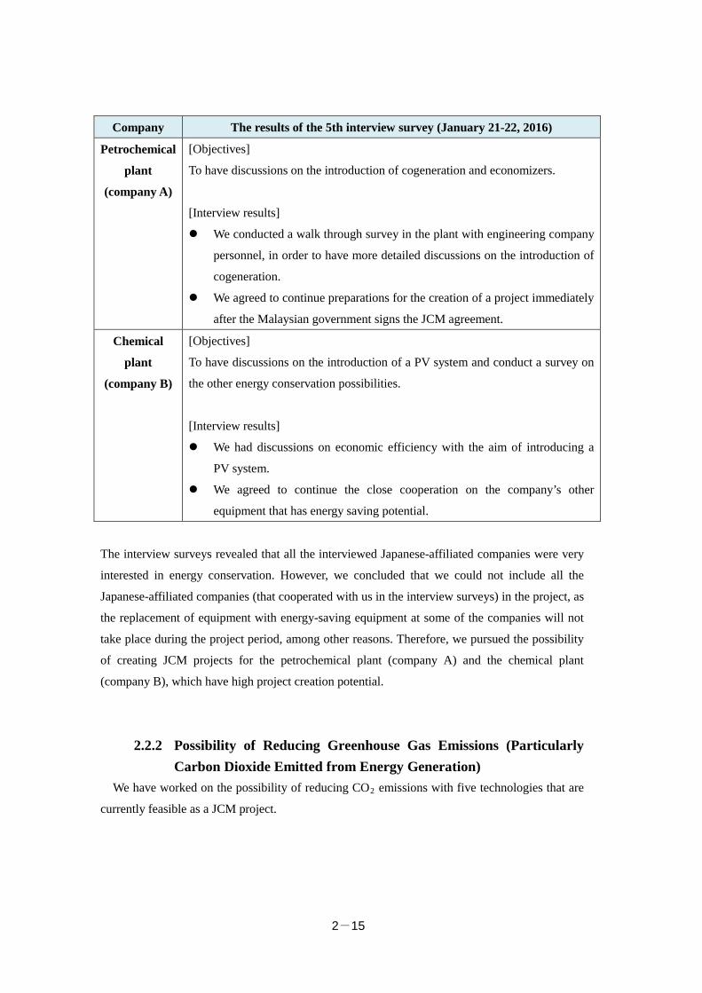
Company The results of the 5th interview survey (January 21-22, 2016)
Petrochemical
plant
(company A)
[Objectives]
To have discussions on the introduction of cogeneration and economizers.
[Interview results]
We conducted a walk through survey in the plant with engineering company
personnel, in order to have more detailed discussions on the introduction of
cogeneration.
We agreed to continue preparations for the creation of a project immediately
after the Malaysian government signs the JCM agreement.
Chemical
plant
(company B)
[Objectives]
To have discussions on the introduction of a PV system and conduct a survey on
the other energy conservation possibilities.
[Interview results]
We had discussions on economic efficiency with the aim of introducing a
PV system.
We agreed to continue the close cooperation on the company’s other
equipment that has energy saving potential.
The interview surveys revealed that all the interviewed Japanese-affiliated companies were very
interested in energy conservation. However, we concluded that we could not include all the
Japanese-affiliated companies (that cooperated with us in the interview surveys) in the project, as
the replacement of equipment with energy-saving equipment at some of the companies will not
take place during the project period, among other reasons. Therefore, we pursued the possibility
of creating JCM projects for the petrochemical plant (company A) and the chemical plant
(company B), which have high project creation potential.
2.2.2 Possibility of Reducing Greenhouse Gas Emissions (Particularly Carbon Dioxide Emitted from Energy Generation)
We have worked on the possibility of reducing CO2 emissions with five technologies that are
currently feasible as a JCM project.
2-16
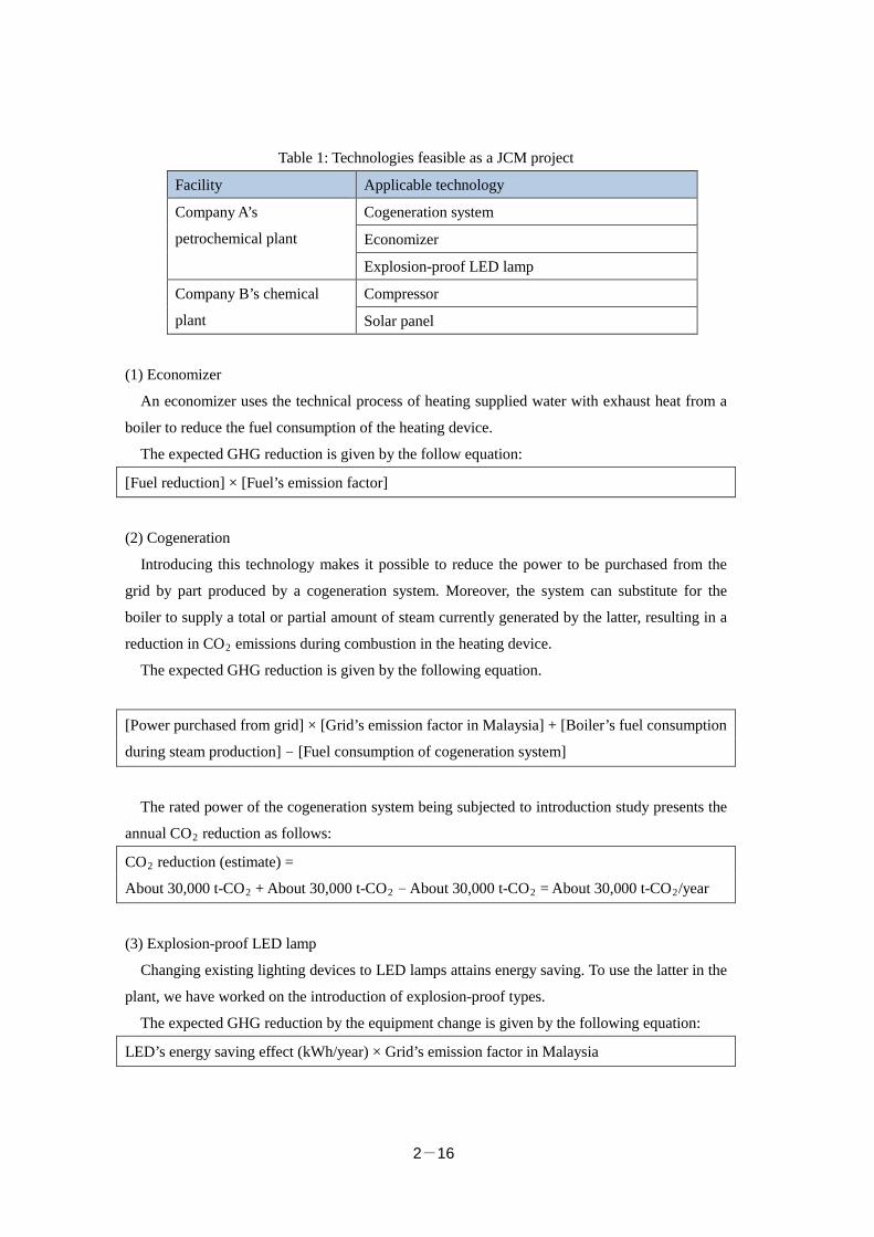
Table 1: Technologies feasible as a JCM project
Facility Applicable technology
Company A’s
petrochemical plant
Cogeneration system
Economizer
Explosion-proof LED lamp
Company B’s chemical
plant
Compressor
Solar panel
(1) Economizer
An economizer uses the technical process of heating supplied water with exhaust heat from a
boiler to reduce the fuel consumption of the heating device.
The expected GHG reduction is given by the follow equation:
[Fuel reduction] × [Fuel’s emission factor]
(2) Cogeneration
Introducing this technology makes it possible to reduce the power to be purchased from the
grid by part produced by a cogeneration system. Moreover, the system can substitute for the
boiler to supply a total or partial amount of steam currently generated by the latter, resulting in a
reduction in CO2 emissions during combustion in the heating device.
The expected GHG reduction is given by the following equation.
[Power purchased from grid] × [Grid’s emission factor in Malaysia] + [Boiler’s fuel consumption
during steam production] - [Fuel consumption of cogeneration system]
The rated power of the cogeneration system being subjected to introduction study presents the
annual CO2 reduction as follows:
CO2 reduction (estimate) =
About 30,000 t-CO2 + About 30,000 t-CO2 - About 30,000 t-CO2 = About 30,000 t-CO2/year
(3) Explosion-proof LED lamp
Changing existing lighting devices to LED lamps attains energy saving. To use the latter in the
plant, we have worked on the introduction of explosion-proof types.
The expected GHG reduction by the equipment change is given by the following equation:
LED’s energy saving effect (kWh/year) × Grid’s emission factor in Malaysia
2-17
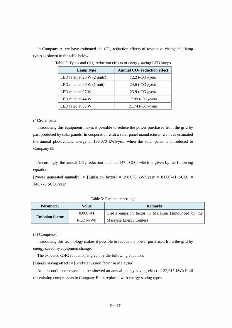
In Company A, we have estimated the CO2 reduction effects of respective changeable lamp
types as shown in the table below.
Table 2: Types and CO2 reduction effects of energy saving LED lamps
Lamp type Annual CO2 reduction effect
LED rated at 26 W (2 units) 12.2 t-CO2/year
LED rated at 26 W (1 unit) 24.6 t-CO2/year
LED rated at 27 W 23.9 t-CO2/year
LED rated at 44 W 17.99 t-CO2/year
LED rated at 33 W 21.74 t-CO2/year
(4) Solar panel
Introducing this equipment makes it possible to reduce the power purchased from the grid by
part produced by solar panels. In cooperation with a solar panel manufacturer, we have estimated
the annual photovoltaic energy at 198,070 kWh/year when the solar panel is introduced to
Company B.
Accordingly, the annual CO2 reduction is about 147 t-CO2, which is given by the following
equation:
[Power generated annually] × [Emission factor] = 198,070 kWh/year × 0.000741 t-CO2 =
146.770 t-CO2/year
Table 3: Parameter settings
Parameter Value Remarks
Emission factor 0.000741
t-CO2/kWh
Grid’s emission factor in Malaysia (announced by the
Malaysia Energy Center)
(5) Compressor
Introducing this technology makes it possible to reduce the power purchased from the grid by
energy saved by equipment change.
The expected GHG reduction is given by the following equation:
[Energy saving effect] × [Grid’s emission factor in Malaysia]
An air conditioner manufacturer showed an annual energy-saving effect of 32,615 kWh if all
the existing compressors in Company B are replaced with energy-saving types.
2-18
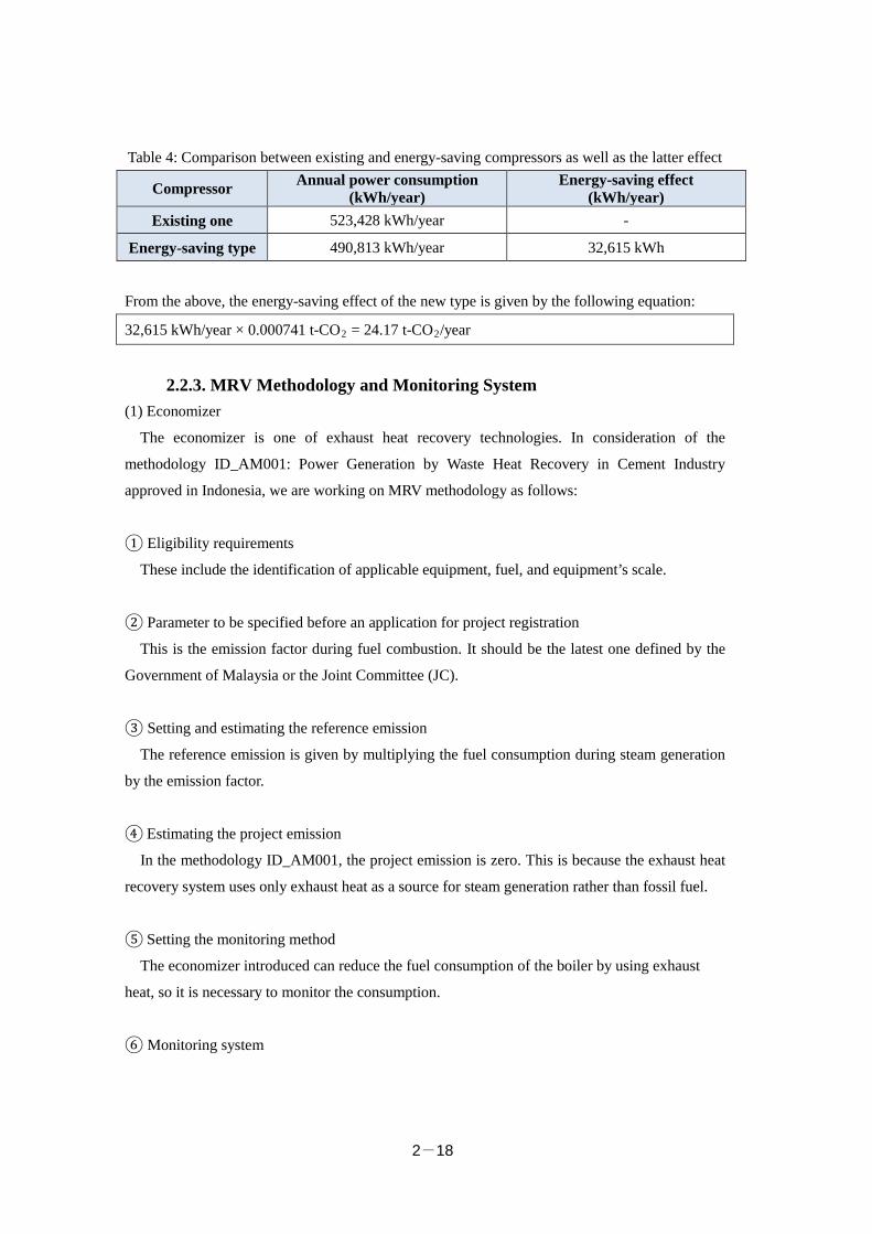
Table 4: Comparison between existing and energy-saving compressors as well as the latter effect
Compressor Annual power consumption (kWh/year)
Energy-saving effect (kWh/year)
Existing one 523,428 kWh/year -
Energy-saving type 490,813 kWh/year 32,615 kWh
From the above, the energy-saving effect of the new type is given by the following equation:
32,615 kWh/year × 0.000741 t-CO2 = 24.17 t-CO2/year
2.2.3. MRV Methodology and Monitoring System (1) Economizer
The economizer is one of exhaust heat recovery technologies. In consideration of the
methodology ID_AM001: Power Generation by Waste Heat Recovery in Cement Industry
approved in Indonesia, we are working on MRV methodology as follows:
① Eligibility requirements
These include the identification of applicable equipment, fuel, and equipment’s scale.
② Parameter to be specified before an application for project registration
This is the emission factor during fuel combustion. It should be the latest one defined by the
Government of Malaysia or the Joint Committee (JC).
③ Setting and estimating the reference emission
The reference emission is given by multiplying the fuel consumption during steam generation
by the emission factor.
④ Estimating the project emission
In the methodology ID_AM001, the project emission is zero. This is because the exhaust heat
recovery system uses only exhaust heat as a source for steam generation rather than fossil fuel.
⑤ Setting the monitoring method
The economizer introduced can reduce the fuel consumption of the boiler by using exhaust
heat, so it is necessary to monitor the consumption.
⑥ Monitoring system
2-19
The on-site staff conducts monitoring activities. If necessary, the Japanese company, a member
of the consortium, gives support. The staff also collects daily data. We work on a system in
which the management is responsible for data checks and monitoring procedures, while the plant
director shall plan and run a project to report the monitoring results.
(2) Cogeneration
① Eligibility requirements
These include the identification of applicable equipment (e.g. gas turbine or engine), fuel,
equipment’s scale, a plant where power and steam produced by cogeneration are consumed, and
a site where the equipment is installed.
② Parameters to be specified before an application for project registration
These include grid’s emission factor, the setup of reference and project facilities, and the
identification of fuel. The first parameter should be the latest one shown by Malaysia.
③ Setting and estimating the reference emission
The reference emission relates to the fuel consumption of the boiler supplying steam with no
cogeneration, so it is given as the sum of the fuel and power consumption.
④ Setting and estimating the project emission
The project emission relates to cogeneration, so it is given by adding the fuel and power
consumption necessary to steam generation.
⑤ Setting the monitoring method
This method includes how to measure the power consumption of the boiler and the power
purchased from the grid, both being set for the reference emission.
⑥ Monitoring system
Receiving support as necessary from the Japanese company, a member of the consortium, the
on-site staff takes the initiative in monitoring activities including the collection of daily data. We
work on a system in which the management is responsible for data checks and monitoring
procedures, while the plant director shall plan and run a project to report the monitoring results.
(2) LED lamp
In Malaysia, no methodology of using LED lamps has been established. Indonesia approves
2-20
the JCM methodology ID_AM005: Installation of LED Lighting for Grocery Store. It is
applicable to food shops but helpful to the development of how to use LED lamps in Malaysia.
ID_AM005 has the concepts of the future method development as shown below.
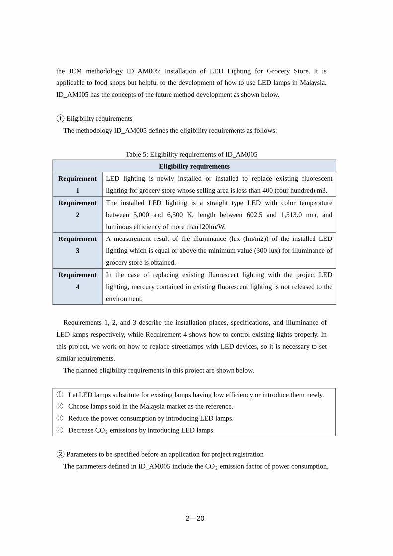
① Eligibility requirements
The methodology ID_AM005 defines the eligibility requirements as follows:
Table 5: Eligibility requirements of ID_AM005
Eligibility requirements
Requirement
1
LED lighting is newly installed or installed to replace existing fluorescent
lighting for grocery store whose selling area is less than 400 (four hundred) m3.
Requirement
2
The installed LED lighting is a straight type LED with color temperature
between 5,000 and 6,500 K, length between 602.5 and 1,513.0 mm, and
luminous efficiency of more than120lm/W.
Requirement
3
A measurement result of the illuminance (lux (lm/m2)) of the installed LED
lighting which is equal or above the minimum value (300 lux) for illuminance of
grocery store is obtained.
Requirement
4
In the case of replacing existing fluorescent lighting with the project LED
lighting, mercury contained in existing fluorescent lighting is not released to the
environment.
Requirements 1, 2, and 3 describe the installation places, specifications, and illuminance of
LED lamps respectively, while Requirement 4 shows how to control existing lights properly. In
this project, we work on how to replace streetlamps with LED devices, so it is necessary to set
similar requirements.
The planned eligibility requirements in this project are shown below.
① Let LED lamps substitute for existing lamps having low efficiency or introduce them newly.
② Choose lamps sold in the Malaysia market as the reference.
③ Reduce the power consumption by introducing LED lamps.
④ Decrease CO2 emissions by introducing LED lamps.
② Parameters to be specified before an application for project registration
The parameters defined in ID_AM005 include the CO2 emission factor of power consumption,
2-21
the optical efficiency of LED lamps to be introduced or changed to, and the optical efficiency of
existing lighting devices regarded as the reference.
In this project, we select the CO2 emission factor, the power consumption, the rated power and
operating time of LED lamps, and the optical efficiency of the reference and LED lamps.
The grid’s CO2 emission factor should be the latest one in Malaysia. Concerning the existing
lighting devices regarded as the reference, we will select a typical lamp after understanding the
road lighting state of Malaysia.
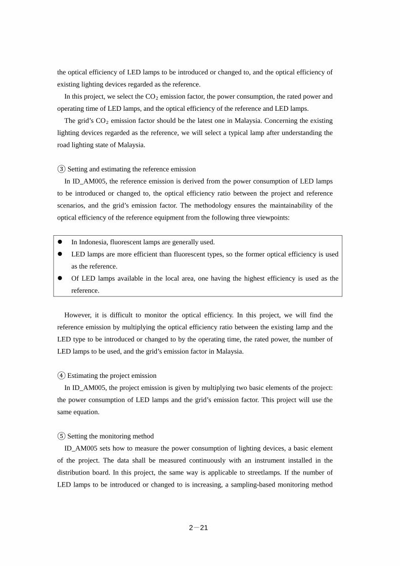
③ Setting and estimating the reference emission
In ID_AM005, the reference emission is derived from the power consumption of LED lamps
to be introduced or changed to, the optical efficiency ratio between the project and reference
scenarios, and the grid’s emission factor. The methodology ensures the maintainability of the
optical efficiency of the reference equipment from the following three viewpoints:
In Indonesia, fluorescent lamps are generally used.
LED lamps are more efficient than fluorescent types, so the former optical efficiency is used
as the reference.
Of LED lamps available in the local area, one having the highest efficiency is used as the
reference.
However, it is difficult to monitor the optical efficiency. In this project, we will find the
reference emission by multiplying the optical efficiency ratio between the existing lamp and the
LED type to be introduced or changed to by the operating time, the rated power, the number of
LED lamps to be used, and the grid’s emission factor in Malaysia.
④ Estimating the project emission
In ID_AM005, the project emission is given by multiplying two basic elements of the project:
the power consumption of LED lamps and the grid’s emission factor. This project will use the
same equation.
⑤ Setting the monitoring method
ID_AM005 sets how to measure the power consumption of lighting devices, a basic element
of the project. The data shall be measured continuously with an instrument installed in the
distribution board. In this project, the same way is applicable to streetlamps. If the number of
LED lamps to be introduced or changed to is increasing, a sampling-based monitoring method

2-22
may be possible.
⑥ Monitoring system
Receiving support as necessary from the Japanese company, a member of the consortium,
Company A, who operates its petrochemical plant, takes the initiative in monitoring activities
including the collection of daily data. We work on a system in which the management is
responsible for data checks and monitoring procedures, while the plant director shall plan and
run a project to report the monitoring results.
(3) Solar panel
Concerning the methodology of introducing solar panels, Palau already approves
PW_AM001: Displacement of Grid and Captive Genset Electricity by a Small-scale Solar PV
System. The Palau method is limited to small-scale systems, but the basic thought is applicable
to this project. Accordingly, we set concepts based on PW_AM001 as shown below.
① Eligibility requirements
The methodology PW_AM001 defines the eligibility requirements as follows:
Table 6
Eligibility requirements
Requirement
1
The project installs solar PV system(s).
Requirement
2
The solar PV system is connected to the internal power grid of the project site and/or to the grid for displacing grid electricity and/or captive electricity at the project site.
Requirement
3
The PV modules have obtained a certification of design qualifications (IEC 61215, IEC 61646 or IEC 62108) and safety qualification (IEC 61730-1 and IEC 61730-2).
Requirement
4
The equipment to monitor output power of the solar PV system and irradiance is installed at the project site.
Requirement 1 describes that the purpose of the project is to introduce a photovoltaic (PV)
power generation system. Requirements 2, 3, and 4 shows the connection between the system
and grid, whether the design of solar cell modules to be introduced is certified, and the system

2-23
output monitors and radiation irradiance respectively.
We think that the same requirements should be specified in Malaysia.
② Parameters to be specified before an application for project registration
These include two CO2 emission factors: one is that of the grid as the reference and the other
is that of the private generator. The Palau methodology uses a power source that consumes diesel
fuel at a power generation efficiency of 49 percent. The default emission factor of the grid is
defined as 0.533 t-CO2/MWh.
It is necessary to set the same parameters in Malaysia. However, the grid’s emission factor
should be the latest one defined in the country.
③ Estimating the reference emission
The reference emission is given by multiplying the power generated by the PV
system—project equipment—and the CO2 emission factors of the grid and private system.
④ Estimating the project emission
We set the project emission at zero.
⑤ Setting the monitoring method
PW_AM001 employs the method of monitoring the power generated by the PV
system—project equipment.
⑥ Monitoring system
Receiving support as necessary from the Japanese company, a member of the consortium, the
on-site staff takes the initiative in monitoring activities including the collection of daily data. We
work on a system in which the management is responsible for data checks and monitoring
procedures, while the plant director shall plan and run a project to report the monitoring results.
(4) Compressor
① Eligibility requirements
These include limitations on the place, technology, and capacity to which the methodology
applies. We think that this project applies to the cooling compressor only in the warehouse.
Concerning the technology, we work on the adoption of the cooling compressor of the
condensing unit. This means that the project applies to the unit only. Regarding the capacity, we
will make a survey of cooling compressors available in Malaysia and select them to the extent
2-24
that the efficiency of the reference equipment can be defined.
The other requirements to be investigated will include ones for setting a benchmark test with
the cooling compressor to which the methodology applies, for making a regular inspection, and
for specifying the ozone depletion factor.
② Parameter to be specified before an application for project registration
These include the grid’s emission factor and the efficiency of the reference and project
equipment. We will get the latter efficiency from the catalog and the former efficiency by making
a survey of products provided by manufacturers having a top share in Malaysia and using the
highest efficiency as the reference. The grid’s emission factor should be the latest one defined by
the country.
③Setting and estimating the reference emission
We work on a method of finding the reference emission by multiplying the power
consumption of the project equipment, the efficiency ratio between the project and reference
facilities, and the grid’s emission factor. The last one should be the latest factor defined by
Malaysia.
④ Estimating the project emission
We work on a method of deriving the project emission from the power consumption of the
project equipment and the grid’s emission factor.
⑤ Setting the monitoring method
We will monitor the power consumption of the compressor relating to the project emission and
the power purchased from the grid.
⑥ Monitoring system
Receiving support as necessary from the Japanese company, a member of the consortium, the
on-site staff takes the initiative in monitoring activities including the collection of daily data. We
work on a system in which the management is responsible for data checks and monitoring
procedures, while the plant director shall plan and run a project to report the monitoring results.
2.2.4. Estimated Project Cost and its Effectiveness (1) Economizer
2-25
We will continue to find the in-depth project cost in the next fiscal year.
(2) Cogeneration
The informative cost of cogeneration to be introduced is 150,000 yen/kW. We plan to install a
cogeneration system rated at 5.2 MW, so the initial investment is given by the following
equation:
Initial investment (estimate) = 5,200 kW × 150,000 yen = 780 million yen
The useful life of cogeneration is 15 years. As a result, the whole project will reduce CO2
emissions as follows:
30,000 t-CO2/year × 15 year = 450,000 t-CO2
The cost effectiveness is given by dividing the initial investment by the CO2 reduction.
Namely, it is 1733.3 yen /t-CO2. If the subsidies hold a 50% share, the cost effectiveness is
867 yen/t-CO2.
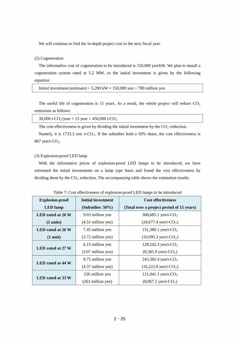
(3) Explosion-proof LED lamp
With the informative prices of explosion-proof LED lamps to be introduced, we have
estimated the initial investments on a lamp type basis and found the cost effectiveness by
dividing them by the CO2 reduction. The accompanying table shows the estimation results.
Table 7: Cost effectiveness of explosion-proof LED lamps to be introduced
Explosion-proof
LED lamp
Initial investment
(Subsidies: 50%)
Cost effectiveness
(Total over a project period of 15 years)
LED rated at 26 W
(2 units)
9.03 million yen
(4.51 million yen)
368,685.1 yen/t-CO2
(24,677.4 yen/t-CO2)
LED rated at 26 W
(1 unit)
7.45 million yen
(3.72 million yen)
151,380.1 yen/t-CO2
(10,095.3 yen/t-CO2)
LED rated at 27 W 6.15 million yen
(3.07 million yen)
128,542.3 yen/t-CO2
(8,585.9 yen/t-CO2)
LED rated at 44 W 8.75 million yen
(4.37 million yen)
243,382.4 yen/t-CO2
(16,222.8 yen/t-CO2)
LED rated at 33 W 526 million yen
(263 million yen)
121,041.1 yen/t-CO2
(8,067.2 yen/t-CO2)
2-26
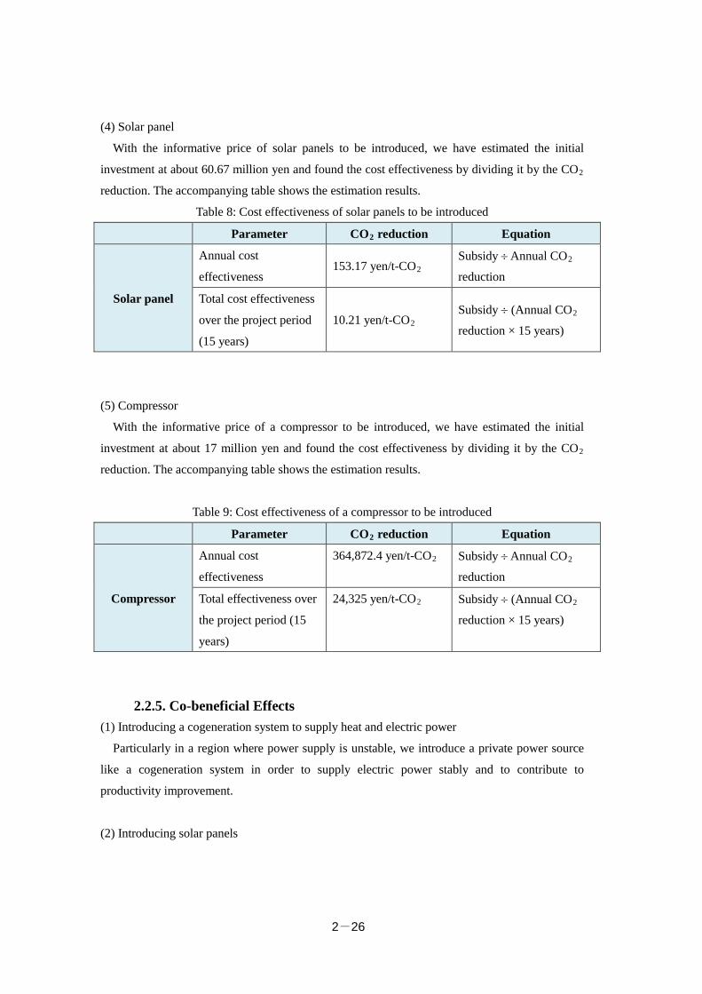
(4) Solar panel
With the informative price of solar panels to be introduced, we have estimated the initial
investment at about 60.67 million yen and found the cost effectiveness by dividing it by the CO2
reduction. The accompanying table shows the estimation results.
Table 8: Cost effectiveness of solar panels to be introduced
Parameter CO2 reduction Equation
Solar panel
Annual cost
effectiveness 153.17 yen/t-CO2
Subsidy ÷ Annual CO2
reduction
Total cost effectiveness
over the project period
(15 years)
10.21 yen/t-CO2 Subsidy ÷ (Annual CO2
reduction × 15 years)
(5) Compressor
With the informative price of a compressor to be introduced, we have estimated the initial
investment at about 17 million yen and found the cost effectiveness by dividing it by the CO2
reduction. The accompanying table shows the estimation results.
Table 9: Cost effectiveness of a compressor to be introduced
Parameter CO2 reduction Equation
Compressor
Annual cost
effectiveness
364,872.4 yen/t-CO2 Subsidy ÷ Annual CO2
reduction
Total effectiveness over
the project period (15
years)
24,325 yen/t-CO2 Subsidy ÷ (Annual CO2
reduction × 15 years)
2.2.5. Co-beneficial Effects (1) Introducing a cogeneration system to supply heat and electric power
Particularly in a region where power supply is unstable, we introduce a private power source
like a cogeneration system in order to supply electric power stably and to contribute to
productivity improvement.
(2) Introducing solar panels
2-27
Introducing solar panels to the rooftop of a warehouse or office building is expected to have a
heat insulation effect. It has the possibility of operating air conditioners in such facilities more
efficiently.
(3) Changing air conditioners and lighting devices
Energy saving results in a reduction in electric power purchased from the grid. Reducing loads
put on the grid is expected to decrease air pollutants, such as ash dust, SOx, and NOx, which are
emitted from coal-fired thermal power stations used as the power source of the grid. It also has
other benefits, such as making power supply stable and reducing the power failure rate.
2.3 Investigation toward a JCM Project There is no joint agreement with Malaysia, but we have conducted work toward a JCM project
assuming that the agreement is made in the next fiscal year or later.
2.3.1 Project Planning (Implementing System, Grant-in-Aid Scheme, and Schedule)
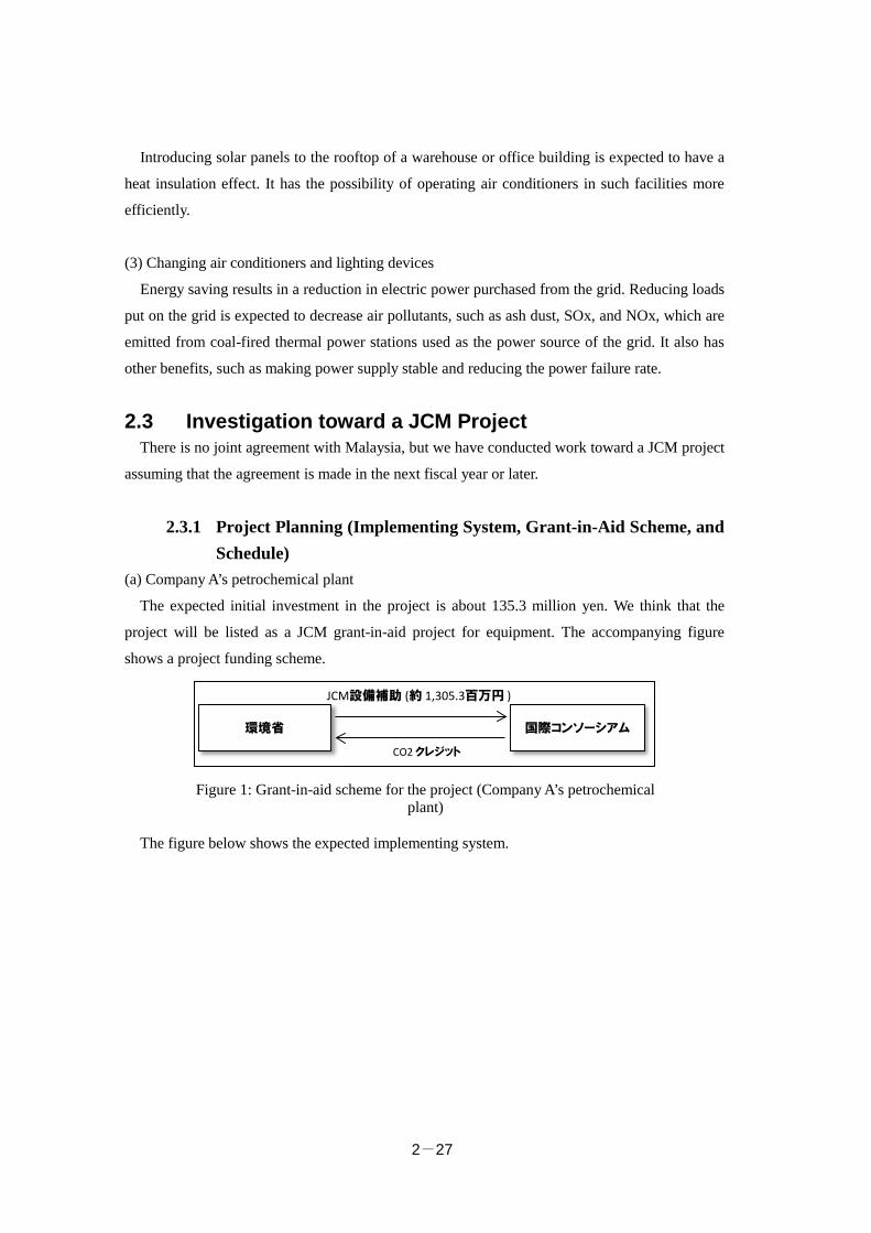
(a) Company A’s petrochemical plant
The expected initial investment in the project is about 135.3 million yen. We think that the
project will be listed as a JCM grant-in-aid project for equipment. The accompanying figure
shows a project funding scheme.
The figure below shows the expected implementing system.
環境省 国際コンソーシアム
JCM設備補助 (約 1,305.3百万円 )
CO2 クレジット
Figure 1: Grant-in-aid scheme for the project (Company A’s petrochemical plant)
2-28
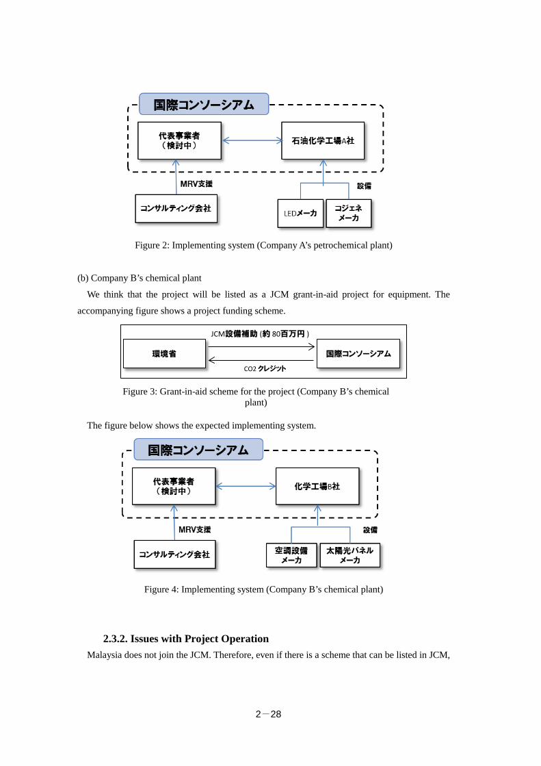
Figure 2: Implementing system (Company A’s petrochemical plant)
(b) Company B’s chemical plant
We think that the project will be listed as a JCM grant-in-aid project for equipment. The
accompanying figure shows a project funding scheme.
The figure below shows the expected implementing system.
Figure 4: Implementing system (Company B’s chemical plant)
2.3.2. Issues with Project Operation Malaysia does not join the JCM. Therefore, even if there is a scheme that can be listed in JCM,
環境省 国際コンソーシアム
JCM設備補助 (約 80百万円 )
CO2 クレジット
Figure 3: Grant-in-aid scheme for the project (Company B’s chemical plant)

2-29
the project activities are restricted in comparison with other member countries. We have to talk
with the individual companies to start the project right after an agreement is concluded while
paying attention to trends in two countries.
2.3.3. Future Schedule Malaysia was a country that did not join the JCM as of February 2016, so we make continuous
preparations for setting up the project after an agreement is concluded. Concerning Company A,
we have to conduct a feasibility study for more concrete design toward the introduction of
cogeneration. Therefore, we will continuously take action to search for and plan projects.
Chapter 3
Waste Field
“Project for Recycling Industrial Waste and Generating
Electric Power from General Waste”
NTT Data Institute of Management Consulting, Inc. AMITA Corporation
Chapter 3 Table of Contents 3.1 Purpose and Implementing System of Project Feasibility Study ..................... 3-1 3.2 Results of the Project Feasibility Study ........................................................... 3-7 3.3 Investigation toward a JCM Project ................................................................. 3-41

3-1
3.1 Purpose and Implementing System of Project Feasibility Study
3.1.1 Outline of the Project (Purpose and Applicable Field) A preliminary survey we have made so far shows that Pasir Gudang City has a variety of
issues shown below.
① The population tends to increase even in the future, resulting in a rise in the amount of
waste generated. In part of the city, waste is separated and collected but it is not
successful because the residents do not have enough awareness.
② Although the Tanjung Langsat landfill in use will be full in 2016, no next one is
determined. Moreover, the disposal site emits methane gas and the treatment of seepage
water is not sufficient.
③ The city has two industrial complexes, so the amount of industrial waste is large.
Moreover, refuse recyclable in Japan is landfilled rather than recycled due to lack of
technology.
Part of the citizens opposes movement toward the introduction of waste incineration and
power generation plant, but it is active particularly in the metropolitan area.
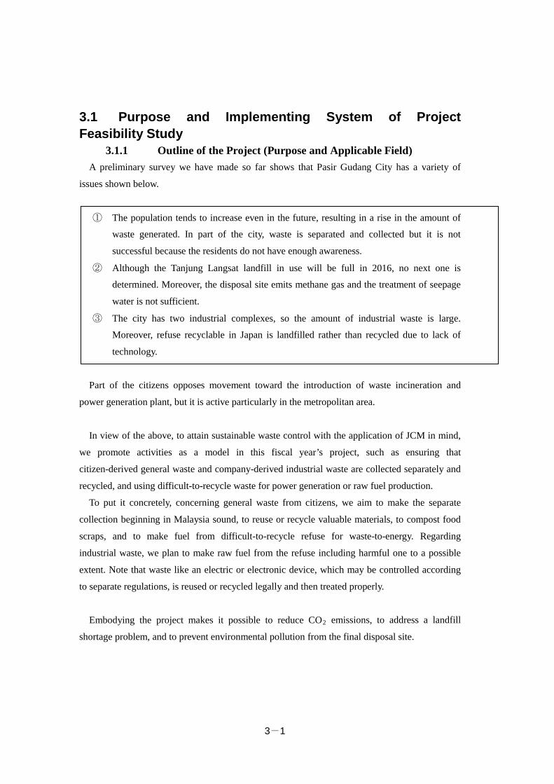
In view of the above, to attain sustainable waste control with the application of JCM in mind,
we promote activities as a model in this fiscal year’s project, such as ensuring that
citizen-derived general waste and company-derived industrial waste are collected separately and
recycled, and using difficult-to-recycle waste for power generation or raw fuel production.
To put it concretely, concerning general waste from citizens, we aim to make the separate
collection beginning in Malaysia sound, to reuse or recycle valuable materials, to compost food
scraps, and to make fuel from difficult-to-recycle refuse for waste-to-energy. Regarding
industrial waste, we plan to make raw fuel from the refuse including harmful one to a possible
extent. Note that waste like an electric or electronic device, which may be controlled according
to separate regulations, is reused or recycled legally and then treated properly.
Embodying the project makes it possible to reduce CO2 emissions, to address a landfill
shortage problem, and to prevent environmental pollution from the final disposal site.
3-2
Figure: Sustainable waste control system as a model (schematic diagram)
3.1.2 Applicable Technologies and Related Legal Systems Applicable technologies
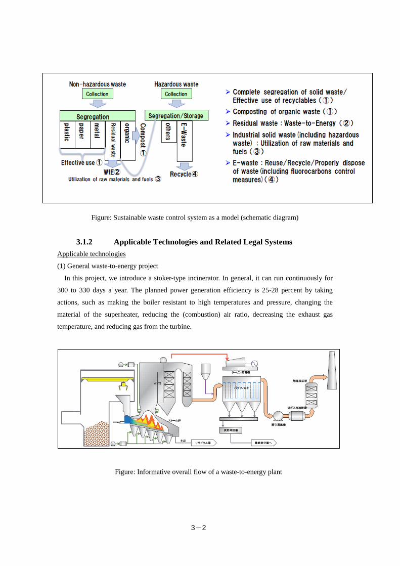
(1) General waste-to-energy project
In this project, we introduce a stoker-type incinerator. In general, it can run continuously for
300 to 330 days a year. The planned power generation efficiency is 25-28 percent by taking
actions, such as making the boiler resistant to high temperatures and pressure, changing the
material of the superheater, reducing the (combustion) air ratio, decreasing the exhaust gas
temperature, and reducing gas from the turbine.
Figure: Informative overall flow of a waste-to-energy plant
3-3
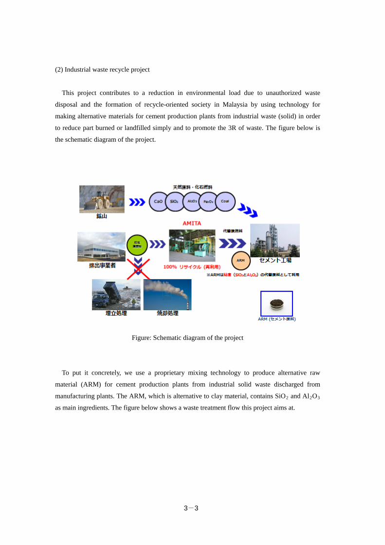
(2) Industrial waste recycle project
This project contributes to a reduction in environmental load due to unauthorized waste
disposal and the formation of recycle-oriented society in Malaysia by using technology for
making alternative materials for cement production plants from industrial waste (solid) in order
to reduce part burned or landfilled simply and to promote the 3R of waste. The figure below is
the schematic diagram of the project.
Figure: Schematic diagram of the project
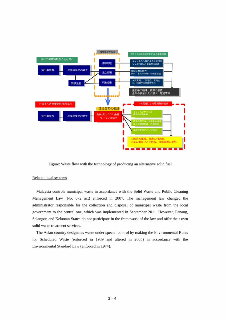
To put it concretely, we use a proprietary mixing technology to produce alternative raw
material (ARM) for cement production plants from industrial solid waste discharged from
manufacturing plants. The ARM, which is alternative to clay material, contains SiO2 and Al2O3
as main ingredients. The figure below shows a waste treatment flow this project aims at.
3-4
Figure: Waste flow with the technology of producing an alternative solid fuel
Related legal systems
Malaysia controls municipal waste in accordance with the Solid Waste and Public Cleaning
Management Law (No. 672 act) enforced in 2007. The management law changed the
administrator responsible for the collection and disposal of municipal waste from the local
government to the central one, which was implemented in September 2011. However, Penang,
Selangor, and Kelantan States do not participate in the framework of the law and offer their own
solid waste treatment services.
The Asian country designates waste under special control by making the Environmental Rules
for Scheduled Waste (enforced in 1989 and altered in 2005) in accordance with the
Environmental Standard Law (enforced in 1974).
1
排出事業者
現状の廃棄物処理の主な流れ焼却処理
埋立処理
不法投棄
産業廃棄物の発生
ダイオキシン等による大気汚染CO2排出による温暖化促進
残余年数の限界臭気、水質汚染等の不衛生管理
水質汚濁、大気汚染、汚職拡大、地域住民の被害拡大
排出事業者 産業廃棄物の発生 合弁リサイクル会社マレーシア製造所
生態系の破壊、資源の浪費企業の事業リスク増大、環境汚染
100%リサイクル資源の有効利用
企業の事業リスクの低減
環境負荷低減、生態系の維持住民の健康保護、汚職抑制
目指すべき廃棄物処理の流れ
リサイクル機能の欠如による環境被害
生態系の保護、資源の利活用、企業の事業リスク低減、環境保護の実現
環境負荷の拡大
環境負荷の低減3R促進による環境負荷低減
回収業者
3-5
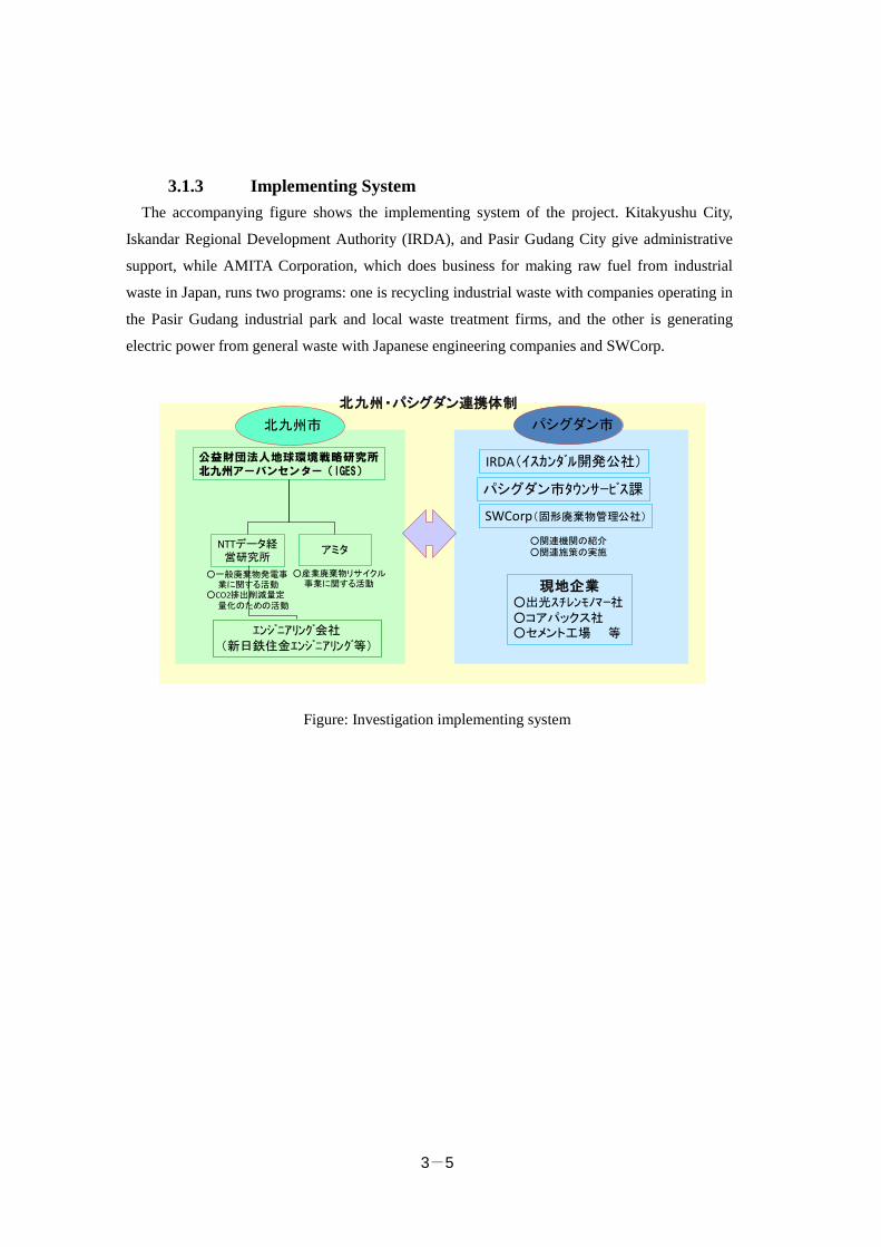
3.1.3 Implementing System The accompanying figure shows the implementing system of the project. Kitakyushu City,
Iskandar Regional Development Authority (IRDA), and Pasir Gudang City give administrative
support, while AMITA Corporation, which does business for making raw fuel from industrial
waste in Japan, runs two programs: one is recycling industrial waste with companies operating in
the Pasir Gudang industrial park and local waste treatment firms, and the other is generating
electric power from general waste with Japanese engineering companies and SWCorp.
Figure: Investigation implementing system
パシグダン市北九州市
北九州・パシグダン連携体制
NTTデータ経営研究所
公益財団法人地球環境戦略研究所北九州アーバンセンター(IGES)
アミタ
○産業廃棄物リサイクル事業に関する活動
○一般廃棄物発電事業に関する活動
○CO2排出削減量定量化のための活動
エンジニアリング会社(新日鉄住金エンジニアリング等)
パシグダン市タウンサービス課
現地企業○出光スチレンモノマー社○コアパックス社○セメント工場 等
○関連機関の紹介○関連施策の実施
SWCorp(固形廃棄物管理公社)
IRDA(イスカンダル開発公社)
3-6
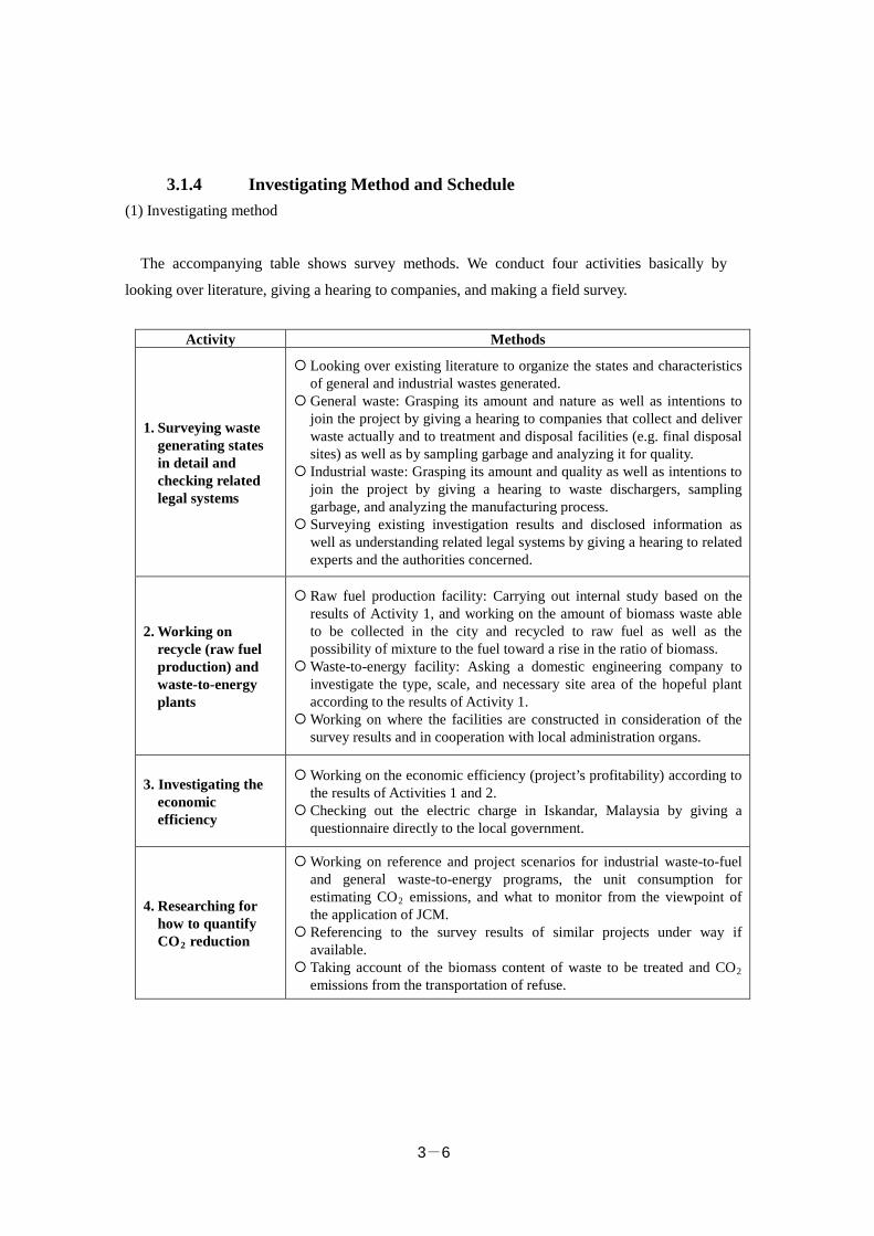
3.1.4 Investigating Method and Schedule (1) Investigating method
The accompanying table shows survey methods. We conduct four activities basically by
looking over literature, giving a hearing to companies, and making a field survey.
Activity Methods
1. Surveying waste generating states in detail and checking related legal systems
Looking over existing literature to organize the states and characteristics of general and industrial wastes generated.
General waste: Grasping its amount and nature as well as intentions to join the project by giving a hearing to companies that collect and deliver waste actually and to treatment and disposal facilities (e.g. final disposal sites) as well as by sampling garbage and analyzing it for quality.
Industrial waste: Grasping its amount and quality as well as intentions to join the project by giving a hearing to waste dischargers, sampling garbage, and analyzing the manufacturing process.
Surveying existing investigation results and disclosed information as well as understanding related legal systems by giving a hearing to related experts and the authorities concerned.
2. Working on recycle (raw fuel production) and waste-to-energy plants
Raw fuel production facility: Carrying out internal study based on the results of Activity 1, and working on the amount of biomass waste able to be collected in the city and recycled to raw fuel as well as the possibility of mixture to the fuel toward a rise in the ratio of biomass.
Waste-to-energy facility: Asking a domestic engineering company to investigate the type, scale, and necessary site area of the hopeful plant according to the results of Activity 1.
Working on where the facilities are constructed in consideration of the survey results and in cooperation with local administration organs.
3. Investigating the economic efficiency
Working on the economic efficiency (project’s profitability) according to the results of Activities 1 and 2.
Checking out the electric charge in Iskandar, Malaysia by giving a questionnaire directly to the local government.
4. Researching for how to quantify CO2 reduction
Working on reference and project scenarios for industrial waste-to-fuel and general waste-to-energy programs, the unit consumption for estimating CO2 emissions, and what to monitor from the viewpoint of the application of JCM.
Referencing to the survey results of similar projects under way if available.
Taking account of the biomass content of waste to be treated and CO2 emissions from the transportation of refuse.
3-7
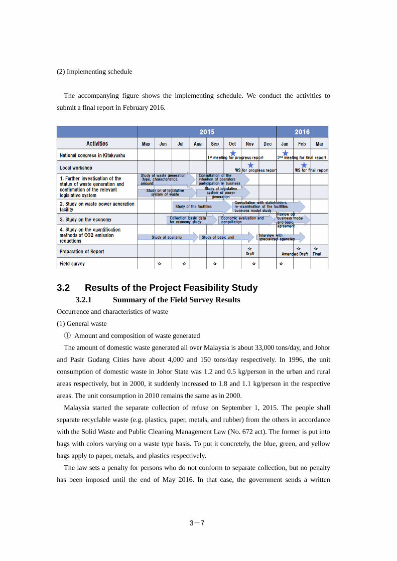
(2) Implementing schedule
The accompanying figure shows the implementing schedule. We conduct the activities to
submit a final report in February 2016.
3.2 Results of the Project Feasibility Study 3.2.1 Summary of the Field Survey Results
Occurrence and characteristics of waste
(1) General waste
① Amount and composition of waste generated
The amount of domestic waste generated all over Malaysia is about 33,000 tons/day, and Johor
and Pasir Gudang Cities have about 4,000 and 150 tons/day respectively. In 1996, the unit
consumption of domestic waste in Johor State was 1.2 and 0.5 kg/person in the urban and rural
areas respectively, but in 2000, it suddenly increased to 1.8 and 1.1 kg/person in the respective
areas. The unit consumption in 2010 remains the same as in 2000.
Malaysia started the separate collection of refuse on September 1, 2015. The people shall
separate recyclable waste (e.g. plastics, paper, metals, and rubber) from the others in accordance
with the Solid Waste and Public Cleaning Management Law (No. 672 act). The former is put into
bags with colors varying on a waste type basis. To put it concretely, the blue, green, and yellow
bags apply to paper, metals, and plastics respectively.
The law sets a penalty for persons who do not conform to separate collection, but no penalty
has been imposed until the end of May 2016. In that case, the government sends a written
3-8
warning to them. From June 1, 2016, a fine of 1,000 ringgit applies to nonconformance.
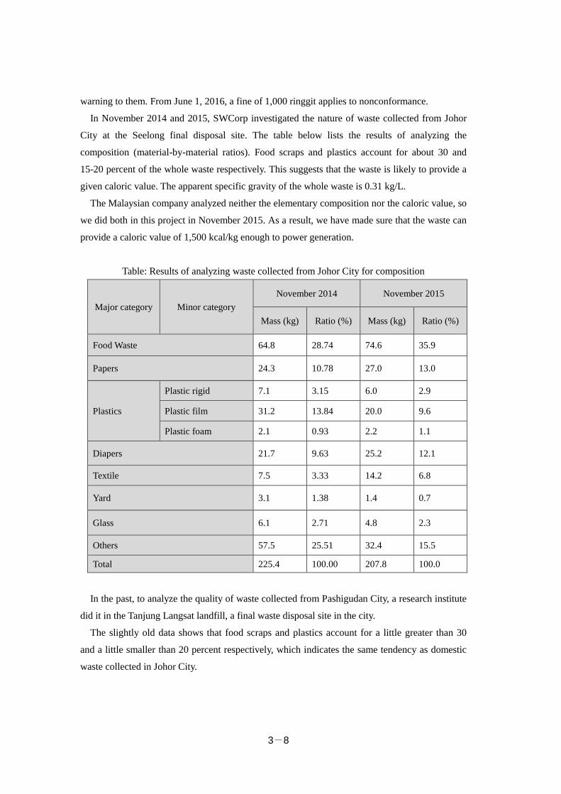
In November 2014 and 2015, SWCorp investigated the nature of waste collected from Johor
City at the Seelong final disposal site. The table below lists the results of analyzing the
composition (material-by-material ratios). Food scraps and plastics account for about 30 and
15-20 percent of the whole waste respectively. This suggests that the waste is likely to provide a
given caloric value. The apparent specific gravity of the whole waste is 0.31 kg/L.
The Malaysian company analyzed neither the elementary composition nor the caloric value, so
we did both in this project in November 2015. As a result, we have made sure that the waste can
provide a caloric value of 1,500 kcal/kg enough to power generation.
Table: Results of analyzing waste collected from Johor City for composition
Major category Minor category November 2014 November 2015
Mass (kg) Ratio (%) Mass (kg) Ratio (%)
Food Waste 64.8 28.74 74.6 35.9
Papers 24.3 10.78 27.0 13.0
Plastics
Plastic rigid 7.1 3.15 6.0 2.9
Plastic film 31.2 13.84 20.0 9.6
Plastic foam 2.1 0.93 2.2 1.1
Diapers 21.7 9.63 25.2 12.1
Textile 7.5 3.33 14.2 6.8
Yard 3.1 1.38 1.4 0.7
Glass 6.1 2.71 4.8 2.3
Others 57.5 25.51 32.4 15.5
Total 225.4 100.00 207.8 100.0
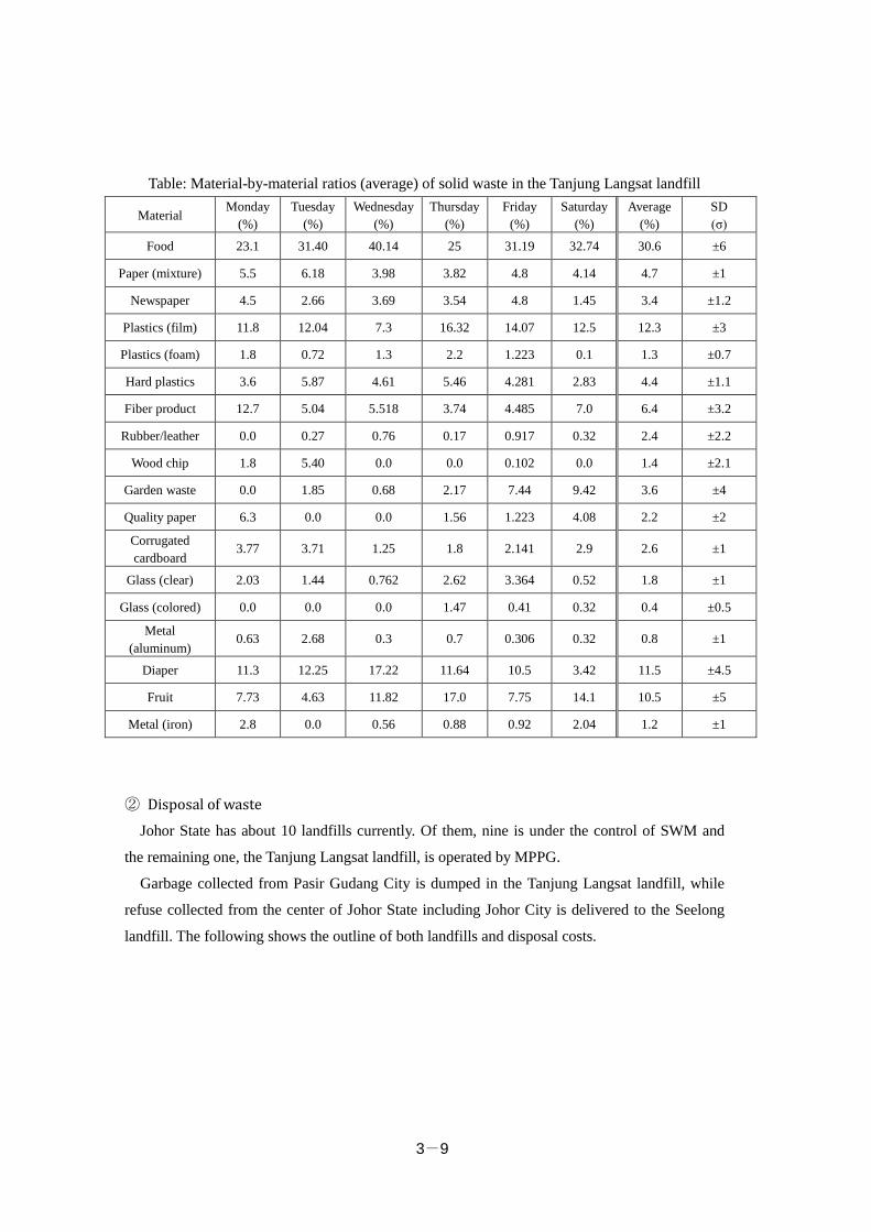
In the past, to analyze the quality of waste collected from Pashigudan City, a research institute
did it in the Tanjung Langsat landfill, a final waste disposal site in the city.
The slightly old data shows that food scraps and plastics account for a little greater than 30
and a little smaller than 20 percent respectively, which indicates the same tendency as domestic
waste collected in Johor City.
3-9
Table: Material-by-material ratios (average) of solid waste in the Tanjung Langsat landfill
Material Monday
(%) Tuesday
(%) Wednesday
(%) Thursday
(%) Friday
(%) Saturday
(%) Average
(%) SD (σ)
Food 23.1 31.40 40.14 25 31.19 32.74 30.6 ±6
Paper (mixture) 5.5 6.18 3.98 3.82 4.8 4.14 4.7 ±1
Newspaper 4.5 2.66 3.69 3.54 4.8 1.45 3.4 ±1.2
Plastics (film) 11.8 12.04 7.3 16.32 14.07 12.5 12.3 ±3
Plastics (foam) 1.8 0.72 1.3 2.2 1.223 0.1 1.3 ±0.7
Hard plastics 3.6 5.87 4.61 5.46 4.281 2.83 4.4 ±1.1
Fiber product 12.7 5.04 5.518 3.74 4.485 7.0 6.4 ±3.2
Rubber/leather 0.0 0.27 0.76 0.17 0.917 0.32 2.4 ±2.2
Wood chip 1.8 5.40 0.0 0.0 0.102 0.0 1.4 ±2.1
Garden waste 0.0 1.85 0.68 2.17 7.44 9.42 3.6 ±4
Quality paper 6.3 0.0 0.0 1.56 1.223 4.08 2.2 ±2
Corrugated cardboard
3.77 3.71 1.25 1.8 2.141 2.9 2.6 ±1
Glass (clear) 2.03 1.44 0.762 2.62 3.364 0.52 1.8 ±1
Glass (colored) 0.0 0.0 0.0 1.47 0.41 0.32 0.4 ±0.5
Metal (aluminum)
0.63 2.68 0.3 0.7 0.306 0.32 0.8 ±1
Diaper 11.3 12.25 17.22 11.64 10.5 3.42 11.5 ±4.5
Fruit 7.73 4.63 11.82 17.0 7.75 14.1 10.5 ±5
Metal (iron) 2.8 0.0 0.56 0.88 0.92 2.04 1.2 ±1
② Disposal of waste
Johor State has about 10 landfills currently. Of them, nine is under the control of SWM and
the remaining one, the Tanjung Langsat landfill, is operated by MPPG.
Garbage collected from Pasir Gudang City is dumped in the Tanjung Langsat landfill, while
refuse collected from the center of Johor State including Johor City is delivered to the Seelong
landfill. The following shows the outline of both landfills and disposal costs.
3-10
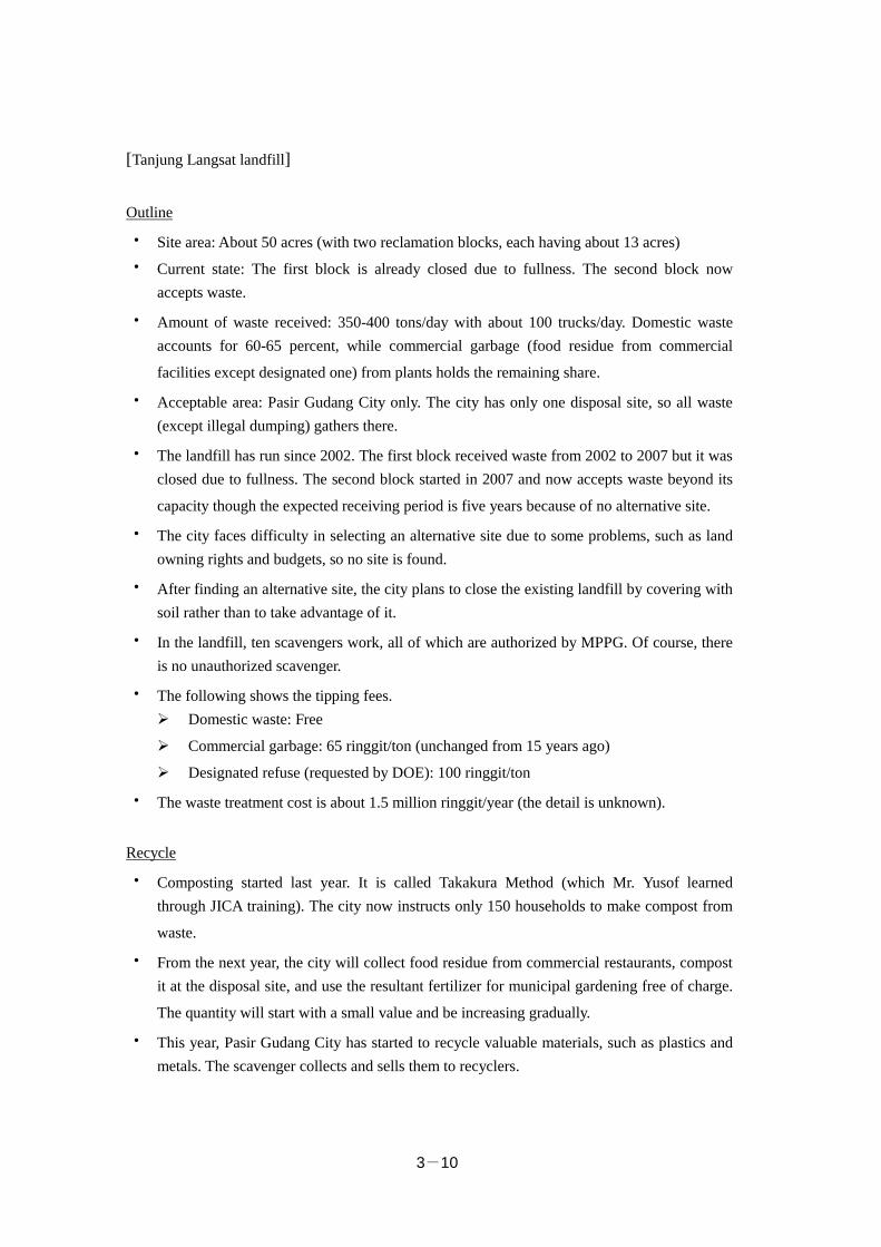
[Tanjung Langsat landfill]
Outline
・ Site area: About 50 acres (with two reclamation blocks, each having about 13 acres)
・ Current state: The first block is already closed due to fullness. The second block now accepts waste.
・ Amount of waste received: 350-400 tons/day with about 100 trucks/day. Domestic waste accounts for 60-65 percent, while commercial garbage (food residue from commercial
facilities except designated one) from plants holds the remaining share.
・ Acceptable area: Pasir Gudang City only. The city has only one disposal site, so all waste (except illegal dumping) gathers there.
・ The landfill has run since 2002. The first block received waste from 2002 to 2007 but it was closed due to fullness. The second block started in 2007 and now accepts waste beyond its
capacity though the expected receiving period is five years because of no alternative site.
・ The city faces difficulty in selecting an alternative site due to some problems, such as land owning rights and budgets, so no site is found.
・ After finding an alternative site, the city plans to close the existing landfill by covering with soil rather than to take advantage of it.
・ In the landfill, ten scavengers work, all of which are authorized by MPPG. Of course, there is no unauthorized scavenger.
・ The following shows the tipping fees. Domestic waste: Free
Commercial garbage: 65 ringgit/ton (unchanged from 15 years ago)
Designated refuse (requested by DOE): 100 ringgit/ton
・ The waste treatment cost is about 1.5 million ringgit/year (the detail is unknown).
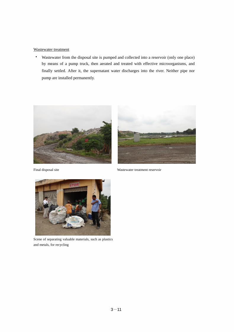
Recycle
・ Composting started last year. It is called Takakura Method (which Mr. Yusof learned through JICA training). The city now instructs only 150 households to make compost from
waste.
・ From the next year, the city will collect food residue from commercial restaurants, compost it at the disposal site, and use the resultant fertilizer for municipal gardening free of charge.
The quantity will start with a small value and be increasing gradually.
・ This year, Pasir Gudang City has started to recycle valuable materials, such as plastics and metals. The scavenger collects and sells them to recyclers.
3-11
Wastewater treatment
・ Wastewater from the disposal site is pumped and collected into a reservoir (only one place) by means of a pump truck, then aerated and treated with effective microorganisms, and
finally settled. After it, the supernatant water discharges into the river. Neither pipe nor
pump are installed permanently.
Final disposal site Wastewater treatment reservoir
Scene of separating valuable materials, such as plastics and metals, for recycling
3-12
[Seelong landfill]
Outline
・ The site area is 275 acres and the reclamation capacity is 1,880 m3 (15 million tons). The person in charge of the Tanjung Langsat landfill says that Johor State owns 92 acres and the
central government has the remainder.
・ Johor Bahru had three disposal sites (e.g. Tahana and Taman), which were closed due to fullness. After that, the Ulu Tiram landfill ran temporarily from 1999 to 2003, but it shut
down because of the vicinity of high-class residential areas. Since 2003, the current landfill
Seelong has been in use.
・ The reclamation period planned initially was 20 years, but Johor State now thinks that the site will be able to run for 30 years (the actual period is unknown). Cells 1 to 4 are already
full.
・ An Australian company (Mounsell) constructed the landfill, and no Japanese company was involved in it.
・ The Seelong landfill, which was complete in May 2003, started to receive waste in January 2004 (more than 10 years have passed).
・ At the disposal site, 40-50 employees (staff) are working.
・ The landfill receives waste from three cities in Johor State: Johor Bahru (MBJB), Johor Bahru Tengah (MPJBT), and Kulai (MPK).
・ The first city has a waste delivery station in Taruka to send garbage collected there to the disposal site.
・ The amount of refuse received is 1,800-2,000 tons/day in 2015, and domestic and industrial wastes account for 70 and 30 percent respectively. The initial forecast was 1,100-2,500
tons/day.
・ Methane gas is collected from Cells 1 to 4 that were full. It has been burned simply without heat recovery, but the state plans to collect energy with a gas engine (rated at 2 MW). The
engine (made in Germany), which is already purchased, is waiting installation and plumbing.
The resulting electricity will be consumed on the premises.
・ The wastewater treatment consists of physicochemical methods (coagulating filtration and separation with film) and a biochemical process (separation with film). The treatment
capacity is 540 m3/day and the amount of wastewater separated with film is 5 m3/day only
(due to costs).
・ The following shows the tipping fees. Waste from local governments: 32.5 ringgit/ton
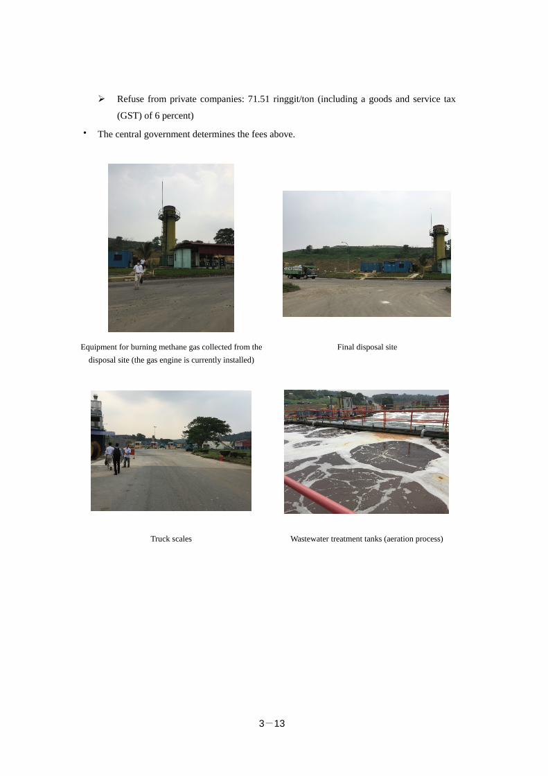
3-13
Refuse from private companies: 71.51 ringgit/ton (including a goods and service tax
(GST) of 6 percent)
・ The central government determines the fees above.
Equipment for burning methane gas collected from the disposal site (the gas engine is currently installed)
Final disposal site
Truck scales Wastewater treatment tanks (aeration process)
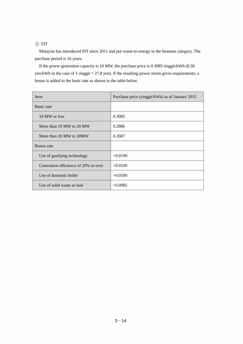
3-14
③ FIT
Malaysia has introduced FIT since 2011 and put waste-to-energy in the biomass category. The
purchase period is 16 years.
If the power generation capacity is 10 MW, the purchase price is 0.3085 ringgit/kWh (8.58
yen/kWh in the case of 1 ringgit = 27.8 yen). If the resulting power meets given requirements, a
bonus is added to the basic rate as shown in the table below.
Item Purchase price (ringgit/kWh) as of January 2015
Basic rate
10 MW or less 0.3085
More than 10 MW to 20 MW 0.2886
More than 20 MW to 30MW 0.2687
Bonus rate
Use of gasifying technology +0.0199
Generation efficiency of 20% or over +0.0100
Use of domestic boiler +0.0500
Use of solid waste as fuel +0.0982
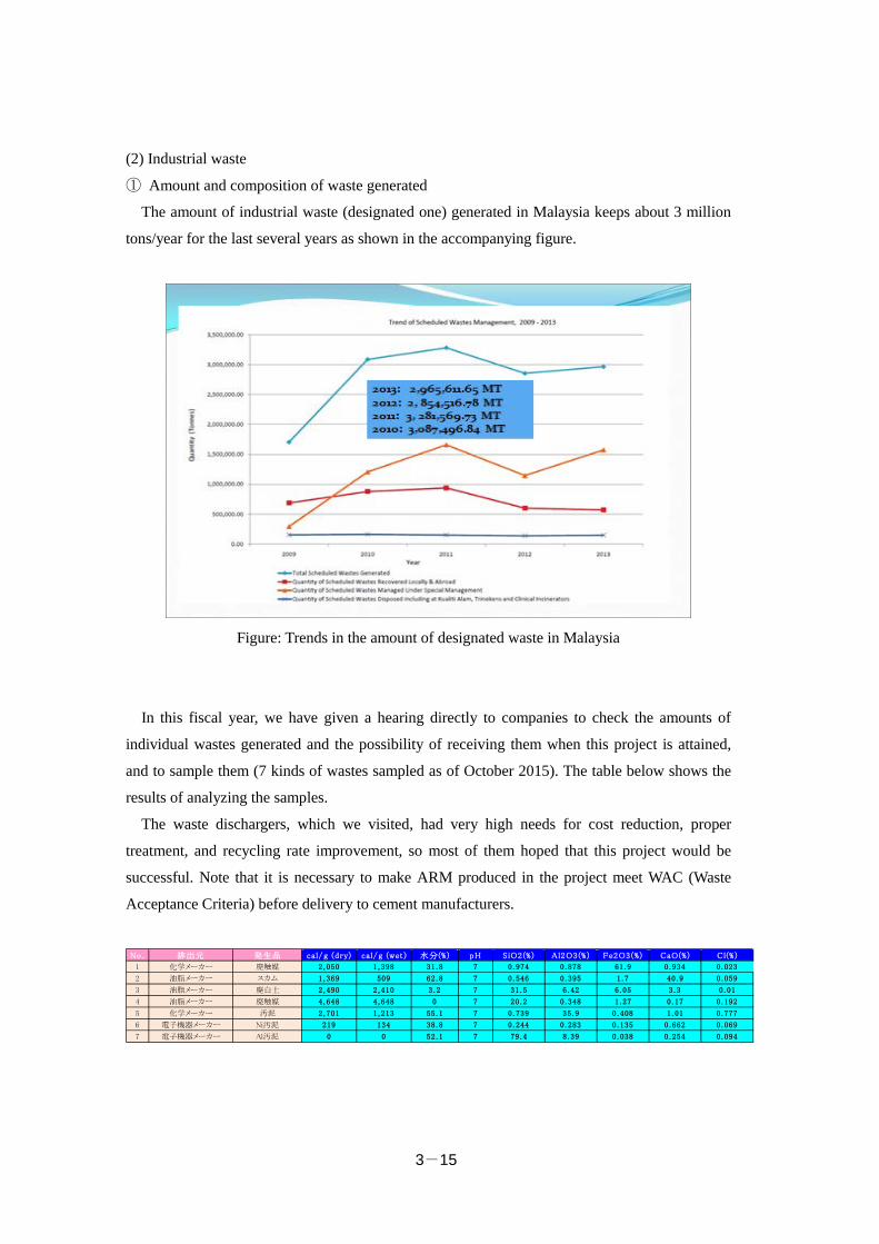
3-15
(2) Industrial waste
① Amount and composition of waste generated
The amount of industrial waste (designated one) generated in Malaysia keeps about 3 million
tons/year for the last several years as shown in the accompanying figure.
Figure: Trends in the amount of designated waste in Malaysia
In this fiscal year, we have given a hearing directly to companies to check the amounts of
individual wastes generated and the possibility of receiving them when this project is attained,
and to sample them (7 kinds of wastes sampled as of October 2015). The table below shows the
results of analyzing the samples.
The waste dischargers, which we visited, had very high needs for cost reduction, proper
treatment, and recycling rate improvement, so most of them hoped that this project would be
successful. Note that it is necessary to make ARM produced in the project meet WAC (Waste
Acceptance Criteria) before delivery to cement manufacturers.
No. 排出元 発生品 cal/g (dry) cal/g (wet ) 水分(%) pH SiO2(% ) Al2O3(%) Fe2O3(%) CaO(%) Cl(% )
1 化学メーカー 廃触媒 2,050 1,398 31.8 7 0.974 0.878 61.9 0.934 0.023
2 油脂メーカー スカム 1,369 509 62.8 7 0.546 0.395 1.7 40.9 0.059
3 油脂メーカー 廃白土 2,490 2,410 3.2 7 31.5 6.42 6.05 3.3 0.01
4 油脂メーカー 廃触媒 4,648 4,648 0 7 20.2 0.348 1.27 0.17 0.192
5 化学メーカー 汚泥 2,701 1,213 55.1 7 0.739 35.9 0.408 1.01 0.777
6 電子機器メーカー Ni汚泥 219 134 38.8 7 0.244 0.283 0.135 0.662 0.069
7 電子機器メーカー Al汚泥 0 0 52.1 7 79.4 8.39 0.038 0.254 0.094
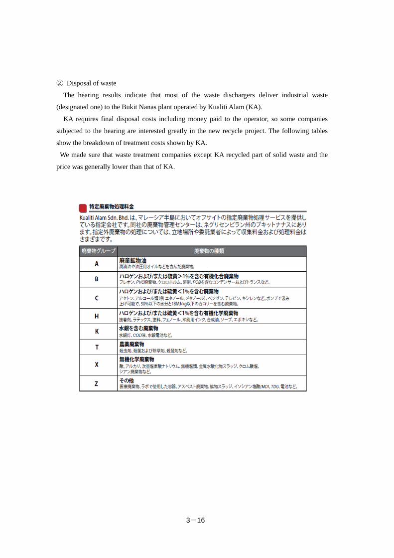
3-16
② Disposal of waste
The hearing results indicate that most of the waste dischargers deliver industrial waste
(designated one) to the Bukit Nanas plant operated by Kualiti Alam (KA).
KA requires final disposal costs including money paid to the operator, so some companies
subjected to the hearing are interested greatly in the new recycle project. The following tables
show the breakdown of treatment costs shown by KA.
We made sure that waste treatment companies except KA recycled part of solid waste and the
price was generally lower than that of KA.
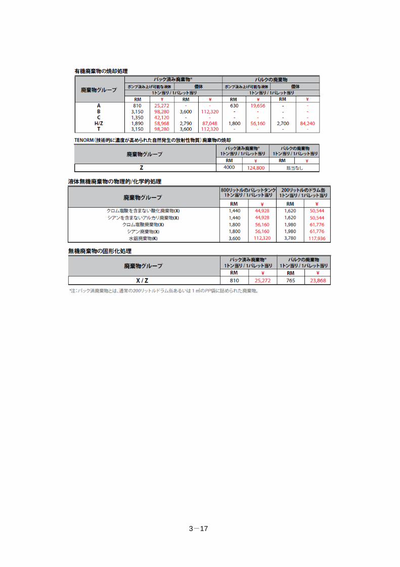
3-17
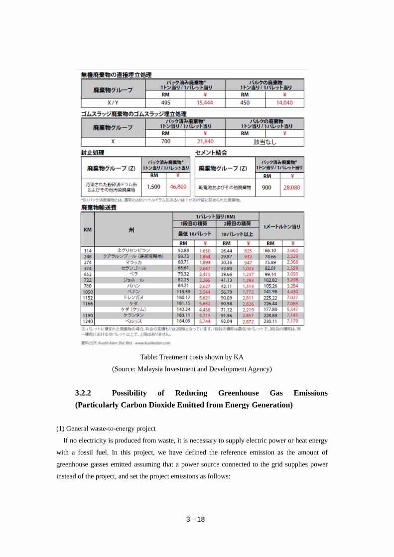
3-18
Table: Treatment costs shown by KA
(Source: Malaysia Investment and Development Agency)
3.2.2 Possibility of Reducing Greenhouse Gas Emissions (Particularly Carbon Dioxide Emitted from Energy Generation)
(1) General waste-to-energy project
If no electricity is produced from waste, it is necessary to supply electric power or heat energy
with a fossil fuel. In this project, we have defined the reference emission as the amount of
greenhouse gasses emitted assuming that a power source connected to the grid supplies power
instead of the project, and set the project emissions as follows:
3-19
1)CO2 emitted by consuming electric power and fuel necessary to incineration and energy
recover.
2)CO2 emitted by burning waste containing fossil resource-derived carbon.
3)Methane may be emitted if wastewater from the incineration process is treated under
anaerobic conditions, but this methodology excludes the gas according to eligibility
requirements.
4)Activities in the project generate GHG during transportation, but this methodology does not
take it into consideration because the resulting emission is almost equal to the reference one.
For example, the project delivers MSW to an incinerator and the resulting ash to an SWDS,
which is equivalent to the movement of MSW to a disposal site in the reference scenario.
(2) Recycling industrial waste
Concerning the possibility of CO2 reduction in this project, we have worked on the following
four scenarios.
1) Making raw fuel derived from industrial waste alternative to coal used in cement plants
2) Replacing simple combustion of industrial waste with recycling
3) Improving the ratio of biomass
4) Reducing the transportation distance
1) Making raw fuel derived from industrial waste alternative to coal used in cement plants
Carbon dioxide emitted during cement production is broken down as follows: about 40 and 60
percent are from the fuel combustion and calcination processes respectively. To check the
possibility of CO2 reduction by material change, we focused on the chemical reaction of the
ingredients of the material in the latter process and compared two cases where the alternative
material was used or not while seeing the CDM methodology—ACM005: Consolidated
Baseline Methodology for Increasing the Blend in Cement Production.
In principle, the work above requires data on carbon density based on the analysis of the
components of the alternative raw fuel and monitoring them. However, it was difficult to get
such data, so we concluded that the estimation was impossible.
Moreover, assuming that the alternative raw fuel has a caloric value equivalent to that of coal
used in an existing cement plant, the former caloric value or input increases, resulting in no CO2
reduction during combustion.
3-20
2) Replacing simple combustion of industrial waste with recycling
In the reference scenario, we assumed that given part of waste was burned simply and that the
project reduced CO2 emitted from the simple combustion. To estimate the reduction, we
introduced the ratio of the part burned simply to the total amount of industrial waste
generated as a parameter.
Our survey paid attention to how to define the ratio conservatively, but we could not get any
quantitative data on the ratio from a hearing.
3) Improving the ratio of biomass to avoid methane emissions at disposal sites (and CO2
reduction by improving the biomass-to-energy ratio during power generation with exhaust
heat recovery)
In Malaysia, buyers basically deal with industrial biomass waste as valuable to use it
effectively, so a small amount of such waste landfilled may contribute to methane fermentation.
Accordingly, this scenario may not result in CO2 reduction.
4) Reducing the transportation distance
In the reference scenario, waste, which currently moves from Johor State to KA, is sent to the
plant in Selangor State by ship. Therefore, we have worked on its CO2 reduction effect.
3.2.3 MRV Methodology and Monitoring System
(1) General waste-to-energy project
1) Applicable GHG reduction technology
This methodology is a renewable energy technology of producing heat energy or electric
power by incinerating municipal solid waste (MSW), that is to say, it is alternative to fossil fuel
use technology. The following table describes terms and definitions used in this document.
Term Definition
Fresh waste Solid refuse delivered to a disposal site but not yet treated. It
includes municipal garbage but excludes treated or harmful
waste.
Incineration To burn organic matter derived from fossil resources and living
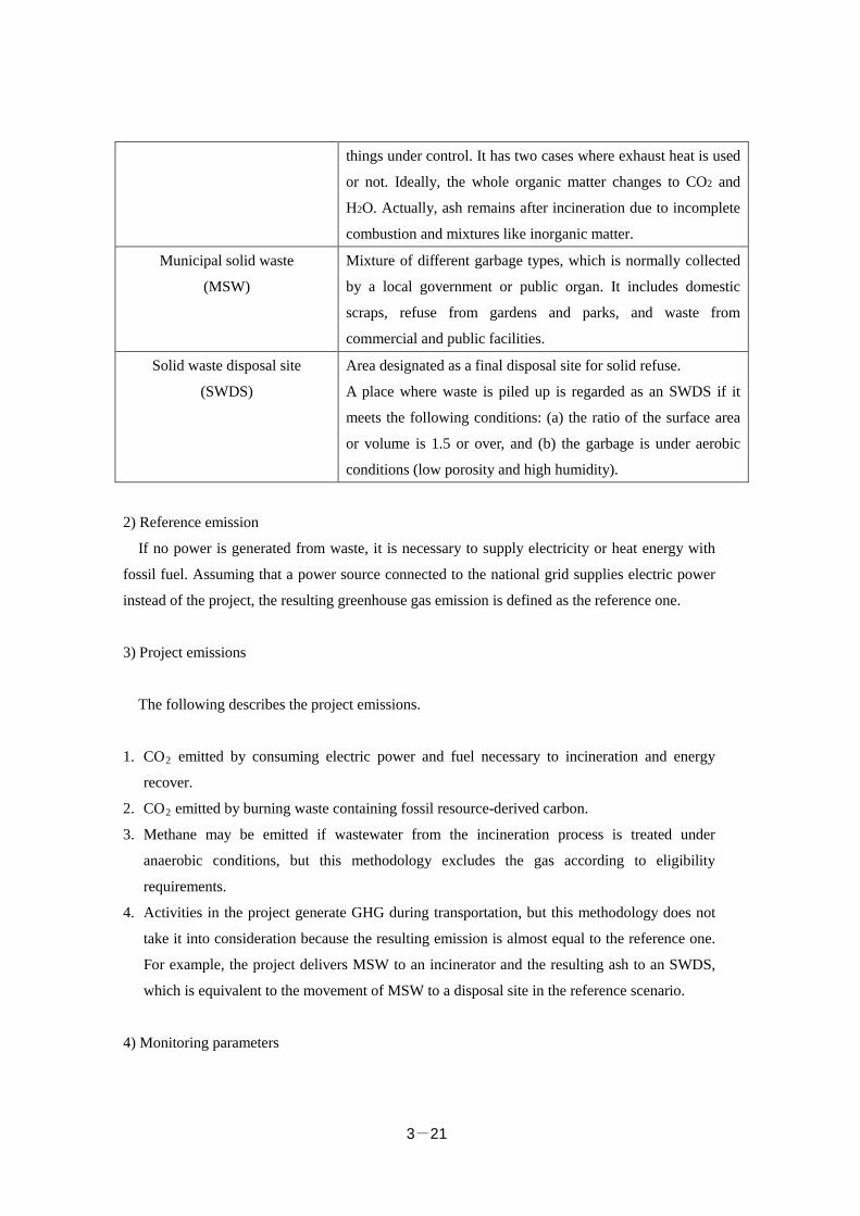
3-21
things under control. It has two cases where exhaust heat is used
or not. Ideally, the whole organic matter changes to CO2 and
H2O. Actually, ash remains after incineration due to incomplete
combustion and mixtures like inorganic matter.
Municipal solid waste
(MSW)
Mixture of different garbage types, which is normally collected
by a local government or public organ. It includes domestic
scraps, refuse from gardens and parks, and waste from
commercial and public facilities.
Solid waste disposal site
(SWDS)
Area designated as a final disposal site for solid refuse.
A place where waste is piled up is regarded as an SWDS if it
meets the following conditions: (a) the ratio of the surface area
or volume is 1.5 or over, and (b) the garbage is under aerobic
conditions (low porosity and high humidity).
2) Reference emission
If no power is generated from waste, it is necessary to supply electricity or heat energy with
fossil fuel. Assuming that a power source connected to the national grid supplies electric power
instead of the project, the resulting greenhouse gas emission is defined as the reference one.
3) Project emissions
The following describes the project emissions.
1. CO2 emitted by consuming electric power and fuel necessary to incineration and energy
recover.
2. CO2 emitted by burning waste containing fossil resource-derived carbon.
3. Methane may be emitted if wastewater from the incineration process is treated under
anaerobic conditions, but this methodology excludes the gas according to eligibility
requirements.
4. Activities in the project generate GHG during transportation, but this methodology does not
take it into consideration because the resulting emission is almost equal to the reference one.
For example, the project delivers MSW to an incinerator and the resulting ash to an SWDS,
which is equivalent to the movement of MSW to a disposal site in the reference scenario.
4) Monitoring parameters
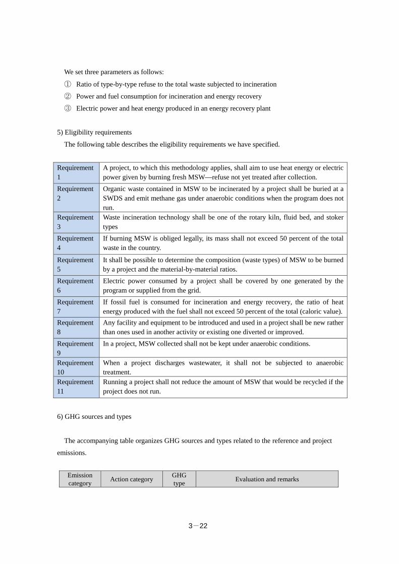
3-22
We set three parameters as follows:
① Ratio of type-by-type refuse to the total waste subjected to incineration
② Power and fuel consumption for incineration and energy recovery
③ Electric power and heat energy produced in an energy recovery plant
5) Eligibility requirements
The following table describes the eligibility requirements we have specified.
Requirement 1
A project, to which this methodology applies, shall aim to use heat energy or electric power given by burning fresh MSW—refuse not yet treated after collection.
Requirement 2
Organic waste contained in MSW to be incinerated by a project shall be buried at a SWDS and emit methane gas under anaerobic conditions when the program does not run.
Requirement 3
Waste incineration technology shall be one of the rotary kiln, fluid bed, and stoker types
Requirement 4
If burning MSW is obliged legally, its mass shall not exceed 50 percent of the total waste in the country.
Requirement 5
It shall be possible to determine the composition (waste types) of MSW to be burned by a project and the material-by-material ratios.
Requirement 6
Electric power consumed by a project shall be covered by one generated by the program or supplied from the grid.
Requirement 7
If fossil fuel is consumed for incineration and energy recovery, the ratio of heat energy produced with the fuel shall not exceed 50 percent of the total (caloric value).
Requirement 8
Any facility and equipment to be introduced and used in a project shall be new rather than ones used in another activity or existing one diverted or improved.
Requirement 9
In a project, MSW collected shall not be kept under anaerobic conditions.
Requirement 10
When a project discharges wastewater, it shall not be subjected to anaerobic treatment.
Requirement 11
Running a project shall not reduce the amount of MSW that would be recycled if the project does not run.
6) GHG sources and types
The accompanying table organizes GHG sources and types related to the reference and project
emissions.
Emission category Action category GHG
type Evaluation and remarks
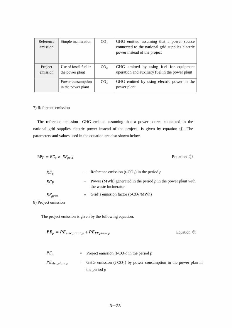
3-23
Reference emission
Simple incineration CO2 GHG emitted assuming that a power source connected to the national grid supplies electric power instead of the project
Project emission
Use of fossil fuel in the power plant
CO2 GHG emitted by using fuel for equipment operation and auxiliary fuel in the power plant
Power consumption in the power plant
CO2 GHG emitted by using electric power in the power plant
7) Reference emission
The reference emission—GHG emitted assuming that a power source connected to the
national grid supplies electric power instead of the project—is given by equation ①. The
parameters and values used in the equation are also shown below.
RE𝑝𝑝 = 𝐸𝐸𝐸𝐸𝑝𝑝 × 𝐸𝐸𝐸𝐸𝑔𝑔𝑔𝑔𝑔𝑔𝑔𝑔 Equation ①
𝑅𝑅𝐸𝐸𝑝𝑝 = Reference emission (t-CO2) in the period p
𝐸𝐸𝐸𝐸𝑝𝑝 = Power (MWh) generated in the period p in the power plant with the waste incinerator
𝐸𝐸𝐸𝐸𝑔𝑔𝑔𝑔𝑔𝑔𝑔𝑔 = Grid’s emission factor (t-CO2/MWh)
8) Project emission
The project emission is given by the following equation:
𝑷𝑷𝑷𝑷𝒑𝒑 = 𝑷𝑷𝑷𝑷𝑒𝑒𝑒𝑒𝑒𝑒𝑒𝑒,𝑝𝑝𝑒𝑒𝑝𝑝𝑝𝑝𝑝𝑝,𝒑𝒑 + 𝑷𝑷𝑷𝑷𝑭𝑭𝑭𝑭,𝒑𝒑𝒑𝒑𝒑𝒑𝒑𝒑𝒑𝒑,𝒑𝒑 Equation ②
𝑃𝑃𝐸𝐸𝑝𝑝 = Project emission (t-CO2) in the period p
𝑃𝑃𝐸𝐸𝑒𝑒𝑒𝑒𝑒𝑒𝑒𝑒,𝑝𝑝𝑒𝑒𝑝𝑝𝑝𝑝𝑝𝑝,𝑝𝑝 = GHG emission (t-CO2) by power consumption in the power plan in
the period p
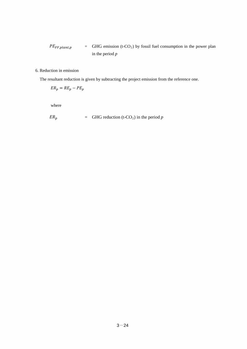
3-24
𝑃𝑃𝐸𝐸𝐹𝐹𝐹𝐹,𝑝𝑝𝑒𝑒𝑝𝑝𝑝𝑝𝑝𝑝,𝑝𝑝 = GHG emission (t-CO2) by fossil fuel consumption in the power plan
in the period p 6. Reduction in emission
The resultant reduction is given by subtracting the project emission from the reference one.
𝐸𝐸𝑅𝑅𝑝𝑝 = 𝑅𝑅𝐸𝐸𝑝𝑝 − 𝑃𝑃𝐸𝐸𝑝𝑝
where
𝐸𝐸𝑅𝑅𝑝𝑝 = GHG reduction (t-CO2) in the period p
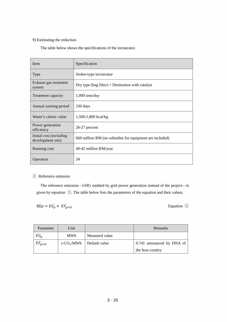
3-25
9) Estimating the reduction
The table below shows the specifications of the incinerator.
Item Specification
Type Stoker-type incinerator
Exhaust gas treatment system Dry type (bag filter) + Denitration with catalyst
Treatment capacity 1,000 tons/day
Annual running period 330 days
Waste’s caloric value 1,500-1,800 kcal/kg
Power generation efficiency 26-27 percent
Initial cost (including development one) 660 million RM (no subsidies for equipment are included)
Running cost 40-42 million RM/year
Operators 34
① Reference emission
The reference emission—GHG emitted by grid power generation instead of the project—is
given by equation ①. The table below lists the parameters of the equation and their values.
RE𝑝𝑝 = 𝐸𝐸𝐸𝐸𝑝𝑝 × 𝐸𝐸𝐸𝐸𝑔𝑔𝑔𝑔𝑔𝑔𝑔𝑔 Equation ①
Parameter Unit Remarks
𝐸𝐸𝐸𝐸𝑝𝑝 MWh Measured value
𝐸𝐸𝐸𝐸𝑔𝑔𝑔𝑔𝑔𝑔𝑔𝑔 t-CO2/MWh Default value 0.741 announced by DNA of
the host country
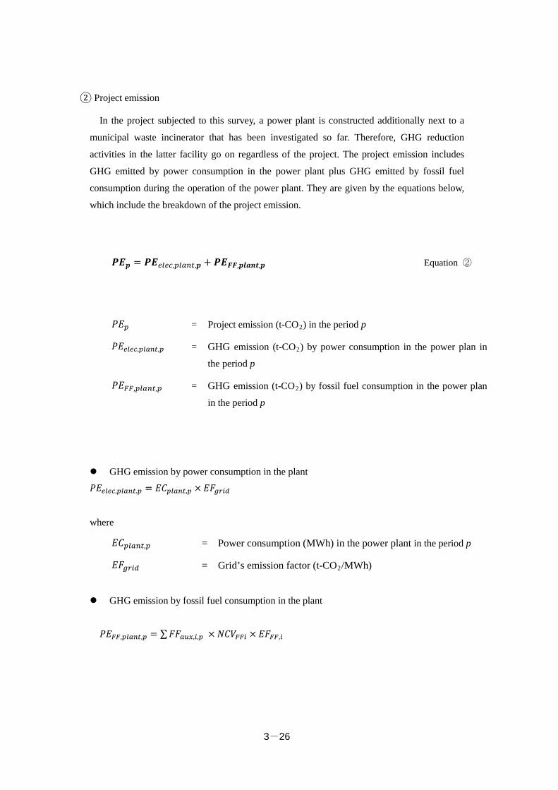
3-26
② Project emission
In the project subjected to this survey, a power plant is constructed additionally next to a
municipal waste incinerator that has been investigated so far. Therefore, GHG reduction
activities in the latter facility go on regardless of the project. The project emission includes
GHG emitted by power consumption in the power plant plus GHG emitted by fossil fuel
consumption during the operation of the power plant. They are given by the equations below,
which include the breakdown of the project emission.
𝑷𝑷𝑷𝑷𝒑𝒑 = 𝑷𝑷𝑷𝑷𝑒𝑒𝑒𝑒𝑒𝑒𝑒𝑒,𝑝𝑝𝑒𝑒𝑝𝑝𝑝𝑝𝑝𝑝,𝒑𝒑 + 𝑷𝑷𝑷𝑷𝑭𝑭𝑭𝑭,𝒑𝒑𝒑𝒑𝒑𝒑𝒑𝒑𝒑𝒑,𝒑𝒑 Equation ②
𝑃𝑃𝐸𝐸𝑝𝑝 = Project emission (t-CO2) in the period p
𝑃𝑃𝐸𝐸𝑒𝑒𝑒𝑒𝑒𝑒𝑒𝑒,𝑝𝑝𝑒𝑒𝑝𝑝𝑝𝑝𝑝𝑝,𝑝𝑝 = GHG emission (t-CO2) by power consumption in the power plan in
the period p
𝑃𝑃𝐸𝐸𝐹𝐹𝐹𝐹,𝑝𝑝𝑒𝑒𝑝𝑝𝑝𝑝𝑝𝑝,𝑝𝑝 = GHG emission (t-CO2) by fossil fuel consumption in the power plan
in the period p
GHG emission by power consumption in the plant
𝑃𝑃𝐸𝐸𝑒𝑒𝑒𝑒𝑒𝑒𝑒𝑒,𝑝𝑝𝑒𝑒𝑝𝑝𝑝𝑝𝑝𝑝.𝑝𝑝 = 𝐸𝐸𝐸𝐸𝑝𝑝𝑒𝑒𝑝𝑝𝑝𝑝𝑝𝑝,𝑝𝑝 × 𝐸𝐸𝐸𝐸𝑔𝑔𝑔𝑔𝑔𝑔𝑔𝑔
where
𝐸𝐸𝐸𝐸𝑝𝑝𝑒𝑒𝑝𝑝𝑝𝑝𝑝𝑝,𝑝𝑝 = Power consumption (MWh) in the power plant in the period p
𝐸𝐸𝐸𝐸𝑔𝑔𝑔𝑔𝑔𝑔𝑔𝑔 = Grid’s emission factor (t-CO2/MWh)
GHG emission by fossil fuel consumption in the plant
𝑃𝑃𝐸𝐸𝐹𝐹𝐹𝐹,𝑝𝑝𝑒𝑒𝑝𝑝𝑝𝑝𝑝𝑝,𝑝𝑝 = ∑𝐸𝐸𝐸𝐸𝑝𝑝𝑎𝑎𝑎𝑎,𝑔𝑔,𝑝𝑝 × 𝑁𝑁𝐸𝐸𝑁𝑁𝐹𝐹𝐹𝐹𝑔𝑔 × 𝐸𝐸𝐸𝐸𝐹𝐹𝐹𝐹,𝑔𝑔
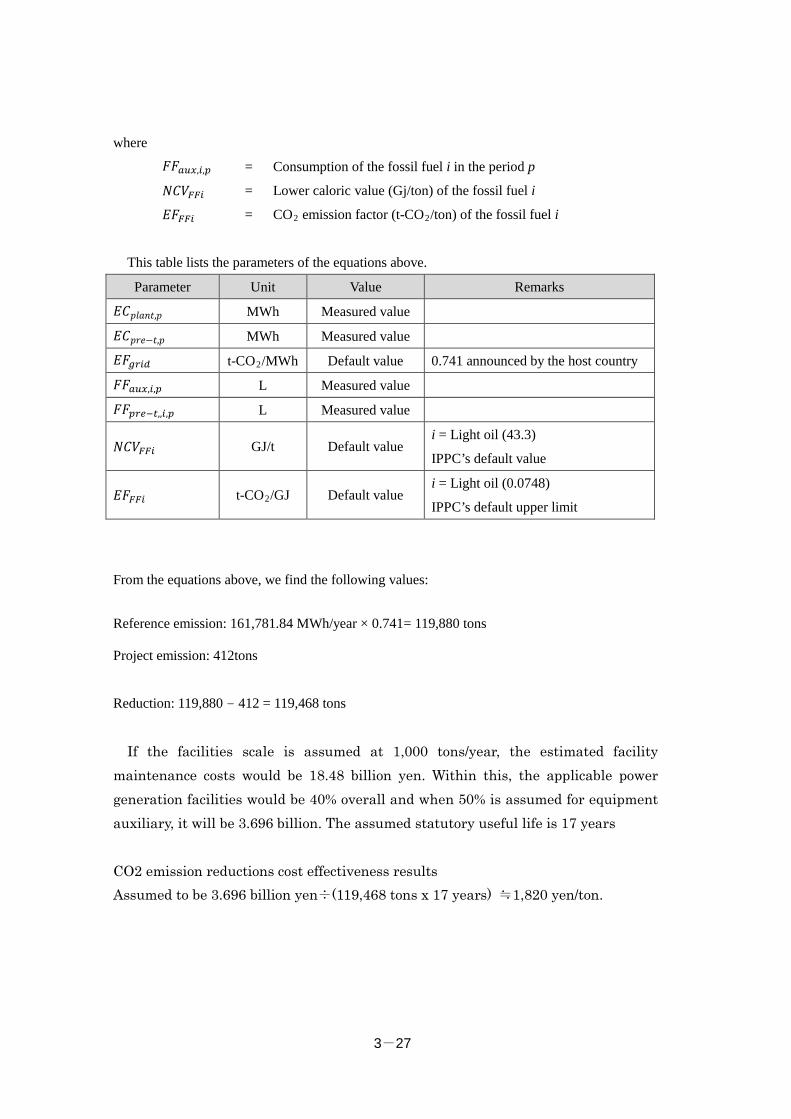
3-27
where
𝐸𝐸𝐸𝐸𝑝𝑝𝑎𝑎𝑎𝑎,𝑔𝑔,𝑝𝑝 = Consumption of the fossil fuel i in the period p
𝑁𝑁𝐸𝐸𝑁𝑁𝐹𝐹𝐹𝐹𝑔𝑔 = Lower caloric value (Gj/ton) of the fossil fuel i
𝐸𝐸𝐸𝐸𝐹𝐹𝐹𝐹𝑔𝑔 = CO2 emission factor (t-CO2/ton) of the fossil fuel i
This table lists the parameters of the equations above.
Parameter Unit Value Remarks
𝐸𝐸𝐸𝐸𝑝𝑝𝑝𝑝𝑝𝑝𝑝𝑝𝑝𝑝,𝑝𝑝 MWh Measured value
𝐸𝐸𝐸𝐸𝑝𝑝𝑝𝑝𝑝𝑝−𝑝𝑝,𝑝𝑝 MWh Measured value
𝐸𝐸𝐸𝐸𝑔𝑔𝑔𝑔𝑔𝑔𝑔𝑔 t-CO2/MWh Default value 0.741 announced by the host country
𝐸𝐸𝐸𝐸𝑝𝑝𝑎𝑎𝑎𝑎,𝑔𝑔,𝑝𝑝 L Measured value
𝐸𝐸𝐸𝐸𝑝𝑝𝑔𝑔𝑒𝑒−𝑝𝑝,,𝑔𝑔,𝑝𝑝 L Measured value
𝑁𝑁𝐸𝐸𝑁𝑁𝐹𝐹𝐹𝐹𝑔𝑔 GJ/t Default value i = Light oil (43.3)
IPPC’s default value
𝐸𝐸𝐸𝐸𝐹𝐹𝐹𝐹𝑔𝑔 t-CO2/GJ Default value i = Light oil (0.0748)
IPPC’s default upper limit
From the equations above, we find the following values:
Reference emission: 161,781.84 MWh/year × 0.741= 119,880 tons
Project emission: 412tons
Reduction: 119,880 - 412 = 119,468 tons
If the facilities scale is assumed at 1,000 tons/year, the estimated facility maintenance costs would be 18.48 billion yen. Within this, the applicable power generation facilities would be 40% overall and when 50% is assumed for equipment auxiliary, it will be 3.696 billion. The assumed statutory useful life is 17 years
CO2 emission reductions cost effectiveness results Assumed to be 3.696 billion yen÷(119,468 tons x 17 years) ≒1,820 yen/ton.
3-28
(2) Recycling industrial waste
This project produces the following three kinds of alternative fuels from waste.
① Alternative solid fuel: CRM-derived fuel
② Alternative liquid fuel: Suramix®
③ Alternative material: CRM
Of the above, Suramix—alternative liquid fuel—features high carbon density, so its CO2
emission during combustion is as high as that of fossil fuel. Moreover, the current reference
scenario does not burn the liquid fuel. Accordingly, we have removed it from the estimation of
CO2 reduction.
CRM, a material alternative to cement, does not contribute to CO2 reduction, but it has a
certain caloric value. Therefore, we have handled the material in the same fashion as
CRM-derived fuel to try to develop a MRV methodology that applies to both according to the
four scenarios mentioned before.
3-29
Methodology to be Proposed to JCM
A. Title
Making Solid Fuel Alternative to that in Cement Production by Recycling Industrial Waste
(Version X.X)
B. Terms and Definitions
Term Definition
Industrial waste Residue from business activities.
Harmful waste
Dangerous and toxic refuse.
It is a residual material that contains a substance regarded as
dangerous and toxic from the viewpoints of its nature, density,
and total content and that pollutes or destructs the environment
directly or indirectly, or that poses a risk to the environment, the
health, and the sustainable life of living things including human
beings through business or other activities. The features include
explosiveness, inflammability, reactivity, toxicity,
infectiousness, and corrosiveness.
Organic waste
Refuse derived mainly from animals or plants, which includes
paper, kitchen garbage, wood, bamboo, fiber, sludge, floral and
faunal residues, and animal excreta.
Preparation technology Resource recycle method that consists of precisely analyzing for
components, caloric value, and repellent presence, working on
preparations that meet product standards for alternative raw
fuels, and checking for blending and conformance.
Alternative solid fuel
Fuel derived from cement raw material (CRM). It is used as an
alternative fuel for cement production and made by mixing
industrial solid wastes, such as sludge, embers, and ash dust to
meet user’s specification.
C. Outline of the Methodology
3-30
Action Description
GHG reduction In this methodology, fossil fuel consumption is reduced by recycling industrial solid waste containing harmful and organic materials in the technical preparation and adjustment processes to make an alternative fuel for cement production. Moreover, promoting resource circulation prevents GHG from being emitted from the simple incineration and reclamation of industrial waste. This means that the former emits CO2 while the latter generates methane gas because the organic content of the waste is discomposed under anaerobic conditions at a disposal site, so both gases stop being emitted into the air by the circulation. Fossil fuel consumption is further reduced by making the transportation distance from industrial waste collection spots to recycle and cement plants shorter than that to incinerators or landfills.
Calculation of the reference emission
1. If no alternative fuel derived from industrial waste is used, CO2 is
emitted by coal fuel consumption for cement production.
[ 1 Alternative to coal]
2. If no industrial waste is recycled, CO2 is emitted by the simple
incineration of waste containing fossil resource-derived carbon.
[ 2 Alternative to simple incineration]
3. If no industrial waste is recycled, methane gas is generated by the
biological breakdown of organic carbon from landfilled refuse under
anaerobic conditions at a disposal site.
[ 3 Avoidance of methane]
4. If no industrial waste is recycled, CO2 is emitted by fossil fuel
consumption during movement from waste collection to treatment and
disposal.
[ 4 Reduction in conveyance distance]
3-31
5. The project is expected to reduce energy consumption at a waste
disposal site because of a reduction in the amount of industrial waste
delivered to the site. However, this methodology does not take this point
into consideration.
Calculation of the project emission
1. CO2 is emitted by fossil fuel consumption during movement from
industrial waste collection spots to a recycle plant and delivery of
alternative fuel from the latter to a cement plant.
2. CO2 is emitted by power and fossil fuel consumption in a recycle plant
where industrial waste is prepared.
3. CO2 is emitted by burning the fossil resource-derived content of
alternative fuel made from industrial waste during cement production.
Monitoring parameters
1. Amount of industrial waste delivered from collection spots to a recycle plant
2. Amount of alternative fuel delivered from the facility above to a cement plant
3. Power and fuel consumption in the recycle plant
4. Quantity, composition, and caloric value of the alternative fuel used for cement production
D. Eligibility criteria
This methodology is applicable to projects that satisfy all the following criteria.
Criterion 1 The project must conduct the intermediate processing of industrial waste which is
currently not treated for disposal after it is collected. The project must then utilize
alternative fuel which will be obtained by recycling industrial waste through
intermediate processing.
3-32
Criterion 2 The industrial waste to be recycled by the project through intermediate processing
must meet one of the following conditions: if the project is not conducted, the
industrial waste will be incinerated and emit CO2 through the combustion of waste
which contains carbon derived from fossil resources; the industrial waste will be
dumped in landfills at waste disposal sites and emit methane gas through
biodegradable organic carbon biodegrading under anaerobic conditions at the waste
disposal sites; or, the industrial waste will cause CO2 emissions through the use of
fossil fuels for long-distance transportation.
Criterion 3 The intermediate processing used in the project must be the recycling of industrial
waste into fuel for cement manufacturing which is of a specific quality, through the
use of the industrial waste blending techniques.
Criterion 4 The blending techniques used in the project must include the following processes:
component analysis of the collected industrial waste; consideration of the blending
rates and combinations which meet the fuel product specifications; blending; and the
analysis of product samples.
Criterion 5 The facilities and equipment to be introduced and used through the project activities
must be new. They must not be converted or improved facilities and equipment
which were or are being used for other activities.
Criterion 6 The project activities must not reduce the amount of industrial waste which would
have been recycled if the project activities did not take place.
E. Emission sources and GHG types
Reference emissions
Emission sources GHG types
Coal fuel consumption at cement plants CO2
Combustion of carbon components derived from fossil resources through
the industrial waste incineration process
CO2
Methane emissions from the anaerobic decomposition of organic waste at
waste disposal sites
CH4
Fossil fuel consumption through the collection of industrial waste and its
transportation to incineration plants and landfill sites
CO2
Project emissions
Emission sources GHG types
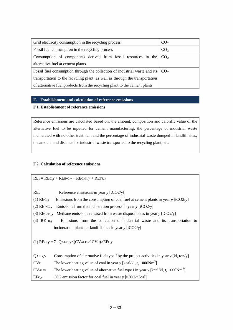
3-33
Grid electricity consumption in the recycling process CO2
Fossil fuel consumption in the recycling process CO2
Consumption of components derived from fossil resources in the
alternative fuel at cement plants
CO2
Fossil fuel consumption through the collection of industrial waste and its
transportation to the recycling plant, as well as through the transportation
of alternative fuel products from the recycling plant to the cement plants.
CO2
F. Establishment and calculation of reference emissions
F.1. Establishment of reference emissions
Reference emissions are calculated based on: the amount, composition and calorific value of the
alternative fuel to be inputted for cement manufacturing; the percentage of industrial waste
incinerated with no other treatment and the percentage of industrial waste dumped in landfill sites;
the amount and distance for industrial waste transported to the recycling plant; etc.
F.2. Calculation of reference emissions
REy = REC,y + REINC,y + RECH4,y + RETR,y
REy Reference emissions in year y [tCO2/y]
(1) REC,y Emissions from the consumption of coal fuel at cement plants in year y [tCO2/y]
(2) REINC,y Emissions from the incineration process in year y [tCO2/y]
(3) RECH4,y Methane emissions released from waste disposal sites in year y [tCO2/y]
(4) RETR,y Emissions from the collection of industrial waste and its transportation to
incineration plants or landfill sites in year y [tCO2/y]
(1) REC,y = Σi QALFi,y×(CVALFi/CVC)×EFC,y
QALFi,y Consumption of alternative fuel type i by the project activities in year y [kl, ton/y]
CVC The lower heating value of coal in year y [kcal/kl, t, 1000Nm3]
CVALFi The lower heating value of alternative fuel type i in year y [kcal/kl, t, 1000Nm3]
EFC,y CO2 emission factor for coal fuel in year y [tCO2/tCoal]
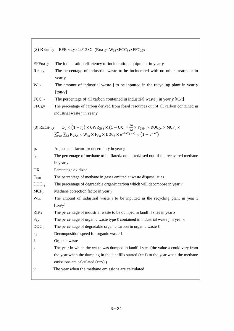
3-34
(2) REINC,y = EFFINC,y×44/12×Σ j (RINC,y×Wj,y×FCCj,y×FFCj,y)
EFFINC,y The incineration efficiency of incineration equipment in year y RINC,y The percentage of industrial waste to be incinerated with no other treatment in
year y Wj,y The amount of industrial waste j to be inputted in the recycling plant in year y
[ton/y] FCCj,y The percentage of all carbon contained in industrial waste j in year y [tC/t] FFCj,y The percentage of carbon derived from fossil resources out of all carbon contained in
industrial waste j in year y
(3) RECH4, y = φy × �1− fy�× GWPCH4 × (1− OX) × 1612
× FCH4 × DOCf,y × MCFy ×
∑ ∑ RLF,x × Wj,xj,ℓyx=1 × Fℓ,x × DOCℓ × e−kℓ(y−x) × �1− e−kℓ�
φy Adjustment factor for uncertainty in year y
fy The percentage of methane to be flared/combusted/used out of the recovered methane
in year y
OX Percentage oxidized
FCH4 The percentage of methane in gases emitted at waste disposal sties
DOCf,y The percentage of degradable organic carbon which will decompose in year y
MCFy Methane correction factor in year y
Wj,x The amount of industrial waste j to be inputted in the recycling plant in year x
[ton/y]
RLF,x The percentage of industrial waste to be dumped in landfill sites in year x
Fℓ,x The percentage of organic waste type ℓ contained in industrial waste j in year x
DOCℓ The percentage of degradable organic carbon in organic waste ℓ
kℓ Decomposition speed for organic waste ℓ
ℓ Organic waste
x The year in which the waste was dumped in landfill sites (the value x could vary from
the year when the dumping in the landfills started (x=1) to the year when the methane
emissions are calculated (x=y).)
y The year when the methane emissions are calculated
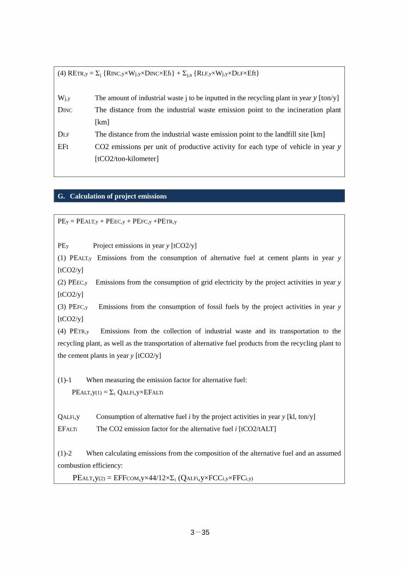
3-35
(4) RETR,y = Σj {RINC,y×Wj,y×DINC×Eft} + Σj,n {RLF,y×Wj,y×DLF×Eft}
Wj,y The amount of industrial waste j to be inputted in the recycling plant in year y [ton/y] DINC The distance from the industrial waste emission point to the incineration plant
[km] DLF The distance from the industrial waste emission point to the landfill site [km]
EFt CO2 emissions per unit of productive activity for each type of vehicle in year y [tCO2/ton-kilometer]
G. Calculation of project emissions
PEy = PEALT,y + PEEC,y + PEFC,y +PETR,y
PEy Project emissions in year y [tCO2/y]
(1) PEALT,y Emissions from the consumption of alternative fuel at cement plants in year y
[tCO2/y]
(2) PEEC,y Emissions from the consumption of grid electricity by the project activities in year y
[tCO2/y]
(3) PEFC,y Emissions from the consumption of fossil fuels by the project activities in year y
[tCO2/y]
(4) PETR,y Emissions from the collection of industrial waste and its transportation to the
recycling plant, as well as the transportation of alternative fuel products from the recycling plant to
the cement plants in year y [tCO2/y]
(1)-1 When measuring the emission factor for alternative fuel:
PEALT,y(1) = Σi QALFi,y×EFALTi
QALFi,y Consumption of alternative fuel i by the project activities in year y [kl, ton/y]
EFALTi The CO2 emission factor for the alternative fuel i [tCO2/tALT]
(1)-2 When calculating emissions from the composition of the alternative fuel and an assumed
combustion efficiency:
PEALT,y(2) = EFFCOM,y×44/12×Σ i (QALFi,y×FCCi,y×FFCi,y)
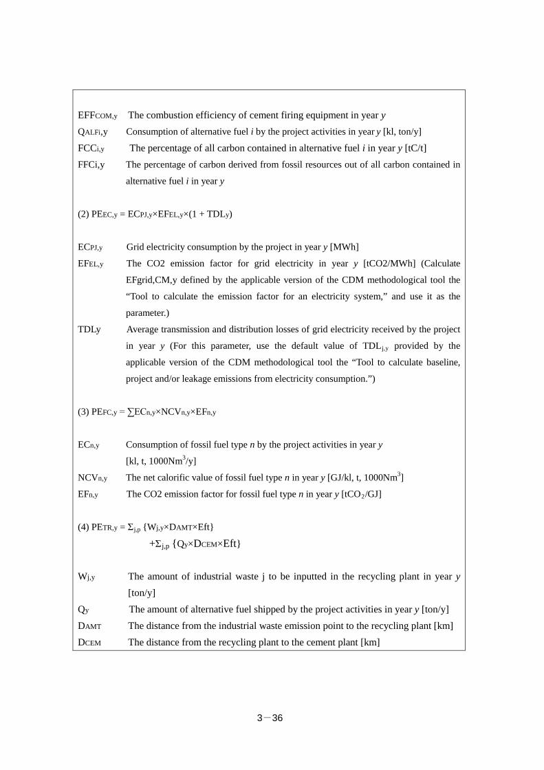
3-36
EFFCOM,y The combustion efficiency of cement firing equipment in year y QALFi,y Consumption of alternative fuel i by the project activities in year y [kl, ton/y]
FCCi,y The percentage of all carbon contained in alternative fuel i in year y [tC/t] FFCi,y The percentage of carbon derived from fossil resources out of all carbon contained in
alternative fuel i in year y
(2) PEEC,y = ECPJ,y×EFEL,y×(1 + TDLy)
ECPJ,y Grid electricity consumption by the project in year y [MWh]
EFEL,y The CO2 emission factor for grid electricity in year y [tCO2/MWh] (Calculate
EFgrid,CM,y defined by the applicable version of the CDM methodological tool the
“Tool to calculate the emission factor for an electricity system,” and use it as the
parameter.)
TDLy Average transmission and distribution losses of grid electricity received by the project
in year y (For this parameter, use the default value of TDLj,y provided by the
applicable version of the CDM methodological tool the “Tool to calculate baseline,
project and/or leakage emissions from electricity consumption.”)
(3) PEFC,y = ∑ECn,y×NCVn,y×EFn,y
ECn,y Consumption of fossil fuel type n by the project activities in year y
[kl, t, 1000Nm3/y]
NCVn,y The net calorific value of fossil fuel type n in year y [GJ/kl, t, 1000Nm3]
EFn,y The CO2 emission factor for fossil fuel type n in year y [tCO2/GJ]
(4) PETR,y = Σj,p {Wj,y×DAMT×Eft}
+Σj,p {Qy×DCEM×Eft}
Wj,y The amount of industrial waste j to be inputted in the recycling plant in year y [ton/y]
Qy The amount of alternative fuel shipped by the project activities in year y [ton/y] DAMT The distance from the industrial waste emission point to the recycling plant [km] DCEM The distance from the recycling plant to the cement plant [km]
3-37
EFp,y CO2 emissions per unit of productive activity for each type of vehicle in year y [tCO2/ton-kilometer]
H. Calculation of emissions reductions
ERy = REy -PEy
ERy GHG emission reductions in year y [tCO2]
REy Reference emissions in year y [tCO2]
PEy Project emissions in year y [tCO2]
It is theoretically possible to calculate CO2 emissions reductions using the above described
calculation methodology, but in reality it is difficult to obtain data for many of the parameters
used in the methodology. Therefore, in this report, CO2 emissions reductions were estimated
using the following method.
ERy = REy -PEy
= (1. CO2 emissions reductions through the replacement of coal at cement plants) + (2.
CO2 emissions reductions through the replacement of incineration without other treatment) +
(3. Methane emissions from disposal sites) – (4. CO2 emissions from electricity and fuel
consumption at the recycling plant) + (5. CO2 emissions reductions through the reduction of
the transportation distance)
The values for “1. CO2 emissions reductions through the replacement of coal at cement plants”
and “3. Methane emissions from disposal sites” are zero, based on the results of the scenario
analysis explained above.
Regarding “2. CO2 emissions reductions through the replacement of industrial waste
incineration without other treatment,” it is not possible to calculate the CO2 emissions from
incineration because the composition of the B3 waste currently being incinerated is unclear. If it
is assumed that 60% of the B3 waste is plastic based on the data for general waste (from the
calculation example in Surabaya1), the annual CO2 emissions reductions are estimated to be
1 The 2014 Fiscal Year Promotion of Projects for the Development of the Japanese Recycling
3-38
approx. 1,100 tons.
“4. CO2 emissions from electricity and fuel consumption at the recycling plant” can be
calculated as follows if the CO2 emissions per unit of productive activity at the Amita
Corporation’s plants in Japan are used: 0.009 (tCO2/ton shipped) × 24,000 tons (shipped) = 216
tons per year.
Concerning “5. Delivery distance reduction,” the reference scenario defines simple
incineration and reclamation by KA, while the project scenario plans to recycle waste at the plant
under construction in Selangor State and to supply the resulting alternative fuel to the cement
plant in Perak State. In this case, no distance reduction is expected, so we set the reduction at
zero.
From the above, the resultant CO2 reduction is given as follows:
ERy = REy -PEy
= “1. Alternative to coal in cement pant” + “2. Alternative to simple incineration”
+ “3. Methane emission from disposal site”
- “4. Power and fuel consumption in recycle plant”
+ “5. Delivery distance reduction”
= 0 + 1,100 + 0 - 216
= 884 tons/year
Accordingly, 884 tons of CO2 is decreased annually.
3.2.4 Estimated Project Cost and its Effectiveness
(1) General waste incineration project
Assuming that the plant capacity is 1,000 tons/year, the project is expected to cost 660 million
RM (about 18,772 million yen in the case of 1 RM = 28.4435 yen). If subsidies account for 50
percent of the power generation equipment cost, 40 percent of the total expenditure, they result
in about 3,754 million yen. We set the statutory useful life at 17 years.
The planned cost effectiveness of CO2 reduction is shown below.
3,754 million yen ÷ (91,551 tons × 17 years) ≈ 2,420 yen/ton
(2) Recycling industrial waste
Industry Overseas “Power Generation from Municipal Solid Waste in Surabaya, Indonesia”

3-39
Assuming that the recycle plant has a CRM production capacity of 42,000 tons/year, it costs
340 million yen. We set the statutory useful life at 17 years.
The planned cost effectiveness of CO2 reduction (with no equipment subsidies from JCM) is
shown below.
340 million yen ÷ (884 tons × 17 years) ≈ 22,630 yen/ton
3-40
3.2.5 Co-beneficial Effects
The general waste-to-energy program can prolong the life of the existing final disposal site
and minimize the construction of new ones by burning municipal waste to reduce part to landfill
(by about 10 percent).
The project for producing alternative raw fuel for cement production from industrial waste is
expected to have three effects:① Reducing the natural resource consumption, ② Prolonging the
life of the final disposal site, and ③ Contributing to recycle-oriented society.
① Reducing the natural resource consumption
Cement material consists of limestone, clay, silica stone, iron oxide material, and plaster.
Producing 1 ton (1,000 kg) of cement requires 1,100 kg of limestone, 200 kg of clay, and 100-
200 kg of the remainder. Malaysia produces about 20 million tons of cement annually. If the
whole cement is made from natural resources, the amounts of limestone, clay, and the remainder
are 22, 4, and 2-4 million tons respectively. This project can reduce the consumption of such
natural resources by making material for alternative raw fuel from massive and various wastes
and by-products from manufacturing or secondary wastes from other treatment companies.
② Prolonging the life of the final disposal site
Making CRM-derived fuel from waste and by-products currently landfilled as well as
secondary refuse can contribute to a reduction in the originally necessary capacity of the final
disposal site and the extension of the site life. In Japan, a report shows that after the cement
industry increased the rate of accepting wastes and by-products to about 28.5 million tons/year in
FY 2012, the life of the final disposal site would extend by eight years, resulting in contribution
to a reduction in environmental load. Prolonging the life also contributes to a reduction in
methane gas and GHG emissions as well as in load put on the environment around the final
disposal site. It is said that Malaysia has more than 150 final disposal sites but environmentally
friendly ones are very few, resulting in worrying about an adverse effect on the surrounding area.
Moreover, some reports indicate that the post-use of closed landfills is not proper, which causes
serious environmental problems including river pollution. Therefore, we are confident that
promoting recycling rather than reclamation will reduce environmental loads in Malaysia.
③ Contributing to recycle-oriented society
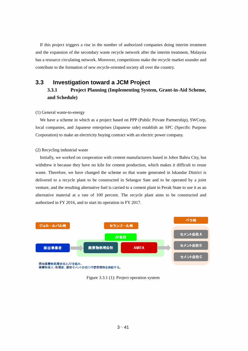
3-41
If this project triggers a rise in the number of authorized companies doing interim treatment
and the expansion of the secondary waste recycle network after the interim treatment, Malaysia
has a resource circulating network. Moreover, competitions make the recycle market sounder and
contribute to the formation of new recycle-oriented society all over the country.
3.3 Investigation toward a JCM Project 3.3.1 Project Planning (Implementing System, Grant-in-Aid Scheme, and Schedule)
(1) General waste-to-energy
We have a scheme in which as a project based on PPP (Public Private Partnership), SWCorp,
local companies, and Japanese enterprises (Japanese side) establish an SPC (Specific Purpose
Corporation) to make an electricity buying contract with an electric power company.
(2) Recycling industrial waste
Initially, we worked on cooperation with cement manufacturers based in Johor Bahru City, but
withdrew it because they have no kiln for cement production, which makes it difficult to reuse
waste. Therefore, we have changed the scheme so that waste generated in Iskandar District is
delivered to a recycle plant to be constructed in Selangor Sate and to be operated by a joint
venture, and the resulting alternative fuel is carried to a cement plant in Perak State to use it as an
alternative material at a rate of 100 percent. The recycle plant aims to be constructed and
authorized in FY 2016, and to start its operation in FY 2017.
Figure 3.3.1 (1): Project operation system
3-42
3.3.2 Issues with Project Operation
In this fiscal year’s survey, we have made sure that producing CRM-derived fuel is feasible as
a result of investigating the current states of waste dischargers and cement manufacturers and
sampling designated refuse to know recycling needs both have. Because there was no cement
plant having a kiln in Iskandar District, we talked with several cement manufacturers based in
Perak State. We have found the following two issues during the survey.
1. Cooperation with a carrier to attain long-distance delivery
The Pasir Gudang industrial region where many Japanese-affiliated companies do business is
more than 400 km far from the planned recycle plant in Selangor State. To attain the collection
and transportation of waste, it is indispensable to cooperate with a land carrier. Malaysia has
many carries that collect and deliver waste, but most of them have a limited action area or a few
trucks. Accordingly, we have to find a carrier that offers a long-distance delivery service and has
many trucks to build up a cooperation system.
2. New competitors
In the Malay Peninsula, Kualiti Alam has made an exclusive contract with the central
government to landfill and burn designated waste. The company was obliged to treat the whole
waste including secondary one, so the effective use of them was restricted. In 2015, the exclusive
contract was expired, resulting in the activation of the recycle market in Malaysia. In Iskandar
District, for example, multiple companies receive and recycle designated waste though the
recycling rate does not reach 100 percent. On the other hand, there are companies that treat waste
illegally, which makes it difficult for the Environment Agency to issue a treatment license and
approval. Anyway, the number of recycling facilities is not enough to the amount of designated
waste, so this movement may be accelerated. To carry on the project in the future, we have to
give importance to in-depth investigation and differentiation study to win the unavoidable
competition.
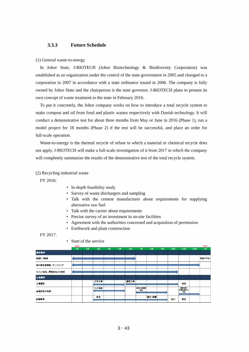
3-43
3.3.3 Future Schedule
(1) General waste-to-energy
In Johor State, J-BIOTECH (Johor Biotechnology & Biodiversity Corporation) was
established as an organization under the control of the state government in 2005 and changed to a
corporation in 2007 in accordance with a state ordinance issued in 2006. The company is fully
owned by Johor State and the chairperson is the state governor. J-BIOTECH plans to present its
own concept of waste treatment to the state in February 2016.
To put it concretely, the Johor company works on how to introduce a total recycle system to
make compost and oil from food and plastic wastes respectively with Danish technology. It will
conduct a demonstrative test for about three months from May or June in 2016 (Phase 1), run a
model project for 18 months (Phase 2) if the test will be successful, and place an order for
full-scale operation.
Waste-to-energy is the thermal recycle of refuse to which a material or chemical recycle does
not apply. J-BIOTECH will make a full-scale investigation of it from 2017 in which the company
will completely summarize the results of the demonstrative test of the total recycle system.
(2) Recycling industrial waste
FY 2016: • In-depth feasibility study • Survey of waste dischargers and sampling • Talk with the cement manufacturer about requirements for supplying
alternative raw fuel • Talk with the carrier about requirements • Precise survey of an investment in on-site facilities • Agreement with the authorities concerned and acquisition of permission • Earthwork and plant construction
FY 2017: • Start of the service
Chapter 4
Supporting Institutional Arrangements to Develop and
Replicate JCM Projects in Iskandar Malaysia
Institute for Global Environmental Strategies
Table of Contents 4.1 Assistance for Institutional Arrangements ........................................................ 4-1 4.2 Organising Workshops ..................................................................................... 4-11 Appendix

4-1
4.1 Assistance for Institutional Arrangements 4.1.1 Summary of the Section
In Iskandar Malaysia, the Low Carbon Society Blueprint for Iskandar Malaysia 2025
(LCSBP) was developed in 2012 in order to help facilitate low-carbon development in the
region. One of the key action items in the LCSBP was the “Iskandar Malaysia LCS
monitoring, reporting and publication system” (LG-4) which suggested conducting CO2
monitoring of buildings. The Iskandar Regional Development Authority (IRDA) has been
seeking ways to address this action item. The current study was therefore undertaken to
identify possible ways to realise the LG-4 action and to assess the potential linkage with the
Joint Crediting Mechanism (JCM).
The current study conducted a literature review and hearing surveys to understand the status
and challenges of the existing CO2 monitoring and green building programmes in and outside
of Malaysia and compiled a report which includes recommendations on how the programme
could possibly collaborate with the JCM scheme. The report was subsequently submitted to
IRDA.
Prospective future developments in collaboration with the JCM include: (i) assessing the
feasibility to apply the building rating system and/or the CO2 monitoring programme, which
IRDA is expecting to introduce, to the industrial factories, and (ii) testing the JCM candidate
buildings (if identified) by using the said building rating system and/or CO2 monitoring
programmes.
4.1.2 Background and Objectives The LCSBP was developed in 2012 in order to enhance low-carbon development of the
Iskandar Malaysia region. It aims to achieve a 40% emission reduction from BaU (business
as usual) by 2025 (using 2005 as the base year) and comprises 12 mitigation actions and over
280 programmes to achieve the emissions reduction target.
In the first consultation meeting with IRDA (on 2 July 2015), it revealed that a system to
conduct CO2 monitoring of buildings (Action LG-4) was not in place and IRDA was looking
for a way to develop such a system. CO2 emissions from buildings and industrial factories
make up a large percentage of total emissions so it is vital to understand the status of CO2
emissions (i.e., energy consumption) as well as to develop a system that could facilitate
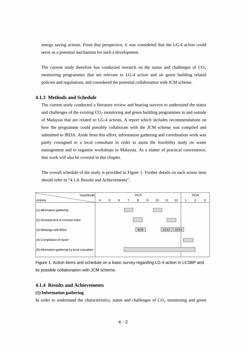
4-2
energy saving actions. From that perspective, it was considered that the LG-4 action could
serve as a potential mechanism for such a development.
The current study therefore has conducted research on the status and challenges of CO2
monitoring programmes that are relevant to LG-4 action and on green building related
policies and regulations, and considered the potential collaboration with JCM scheme.
4.1.3 Methods and Schedule The current study conducted a literature review and hearing surveys to understand the status
and challenges of the existing CO2 monitoring and green building programmes in and outside
of Malaysia that are related to LG-4 actions. A report which includes recommendations on
how the programme could possibly collaborate with the JCM scheme was compiled and
submitted to IRDA. Aside from this effort, information gathering and coordination work was
partly consigned to a local consultant in order to assist the feasibility study on waste
management and to organise workshops in Malaysia. As a matter of practical convenience,
that work will also be covered in this chapter.
The overall schedule of the study is provided in Figure 1. Further details on each action item
should refer to “4.1.4. Results and Achievements”.
Figure 1. Action items and schedule on a basic survey regarding LG-4 action in LCSBP and
its possible collaboration with JCM scheme.
4.1.4 Results and Achievements (1) Information gathering
In order to understand the characteristics, status and challenges of CO2 monitoring and green
Year/MonthActions 4 5 6 7 8 9 10 11 12 1 2 3
(1) Information gathering
(2) Development of concept notes
(3) Meetings with IRDA
(4) Compilation of report
(5) Information gathering by local consultant
2015 2016
8/25 11/12 12/14
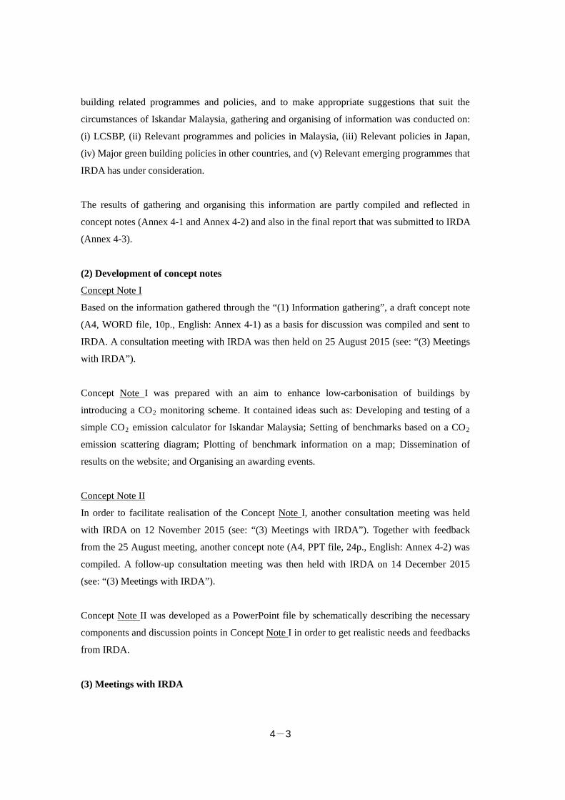
4-3
building related programmes and policies, and to make appropriate suggestions that suit the
circumstances of Iskandar Malaysia, gathering and organising of information was conducted on:
(i) LCSBP, (ii) Relevant programmes and policies in Malaysia, (iii) Relevant policies in Japan,
(iv) Major green building policies in other countries, and (v) Relevant emerging programmes that
IRDA has under consideration.
The results of gathering and organising this information are partly compiled and reflected in
concept notes (Annex 4-1 and Annex 4-2) and also in the final report that was submitted to IRDA
(Annex 4-3).
(2) Development of concept notes
Concept Note I
Based on the information gathered through the “(1) Information gathering”, a draft concept note
(A4, WORD file, 10p., English: Annex 4-1) as a basis for discussion was compiled and sent to
IRDA. A consultation meeting with IRDA was then held on 25 August 2015 (see: “(3) Meetings
with IRDA”).
Concept Note I was prepared with an aim to enhance low-carbonisation of buildings by
introducing a CO2 monitoring scheme. It contained ideas such as: Developing and testing of a
simple CO2 emission calculator for Iskandar Malaysia; Setting of benchmarks based on a CO2
emission scattering diagram; Plotting of benchmark information on a map; Dissemination of
results on the website; and Organising an awarding events.
Concept Note II
In order to facilitate realisation of the Concept Note I, another consultation meeting was held
with IRDA on 12 November 2015 (see: “(3) Meetings with IRDA”). Together with feedback
from the 25 August meeting, another concept note (A4, PPT file, 24p., English: Annex 4-2) was
compiled. A follow-up consultation meeting was then held with IRDA on 14 December 2015
(see: “(3) Meetings with IRDA”).
Concept Note II was developed as a PowerPoint file by schematically describing the necessary
components and discussion points in Concept Note I in order to get realistic needs and feedbacks
from IRDA.
(3) Meetings with IRDA
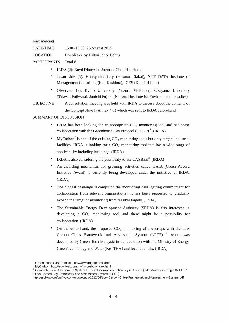
4-4
First meeting
DATE/TIME 15:00-16:30, 25 August 2015
LOCATION Doubletree by Hilton Johor Bahru
PARTICIPANTS Total 8
・ IRDA (2): Boyd Dionysius Joeman, Choo Hui Hong
・ Japan side (3): Kitakyushu City (Hironori Sakai), NTT DATA Institute of Management Consulting (Ken Kashima), IGES (Kohei Hibino)
・ Observers (3): Kyoto University (Yuzuru Matsuoka), Okayama University (Takeshi Fujiwara), Junichi Fujino (National Institute for Environmental Studies)
OBJECTIVE A consultation meeting was held with IRDA to discuss about the contents of
the Concept Note I (Annex 4-1) which was sent to IRDA beforehand.
SUMMARY OF DISCUSSION
・ IRDA has been looking for an appropriate CO2 monitoring tool and had some collaboration with the Greenhouse Gas Protocol (GHGP) 1. (IRDA)
・ MyCarbon2 is one of the existing CO2 monitoring tools but only targets industrial facilities. IRDA is looking for a CO2 monitoring tool that has a wide range of
applicability including buildings. (IRDA)
・ IRDA is also considering the possibility to use CASBEE3. (IRDA)
・ An awarding mechanism for greening activities called GAIA (Green Accord Initiative Award) is currently being developed under the initiative of IRDA.
(IRDA)
・ The biggest challenge is compiling the monitoring data (getting commitment for collaboration from relevant organisations). It has been suggested to gradually
expand the target of monitoring from feasible targets. (IRDA)
・ The Sustainable Energy Development Authority (SEDA) is also interested in developing a CO2 monitoring tool and there might be a possibility for
collaboration. (IRDA)
・ On the other hand, the proposed CO2 monitoring also overlaps with the Low Carbon Cities Framework and Assessment System (LCCF) 4 which was
developed by Green Tech Malaysia in collaboration with the Ministry of Energy,
Green Technology and Water (KeTTHA) and local councils. (IRDA)
1 Greenhouse Gas Protocol: http://www.ghgprotocol.org/ 2 MyCarbon: http://ecoideal.com.my/mycarbon/index.html 3 Comprehensive Assessment System for Built Environment Efficiency (CASBEE):http://www.ibec.or.jp/CASBEE/ 4 Low Carbon City Framework and Assessment System (LCCF): http://esci-ksp.org/wp/wp-content/uploads/2012/04/Low-Carbon-Cities-Framework-and-Assessment-System.pdf
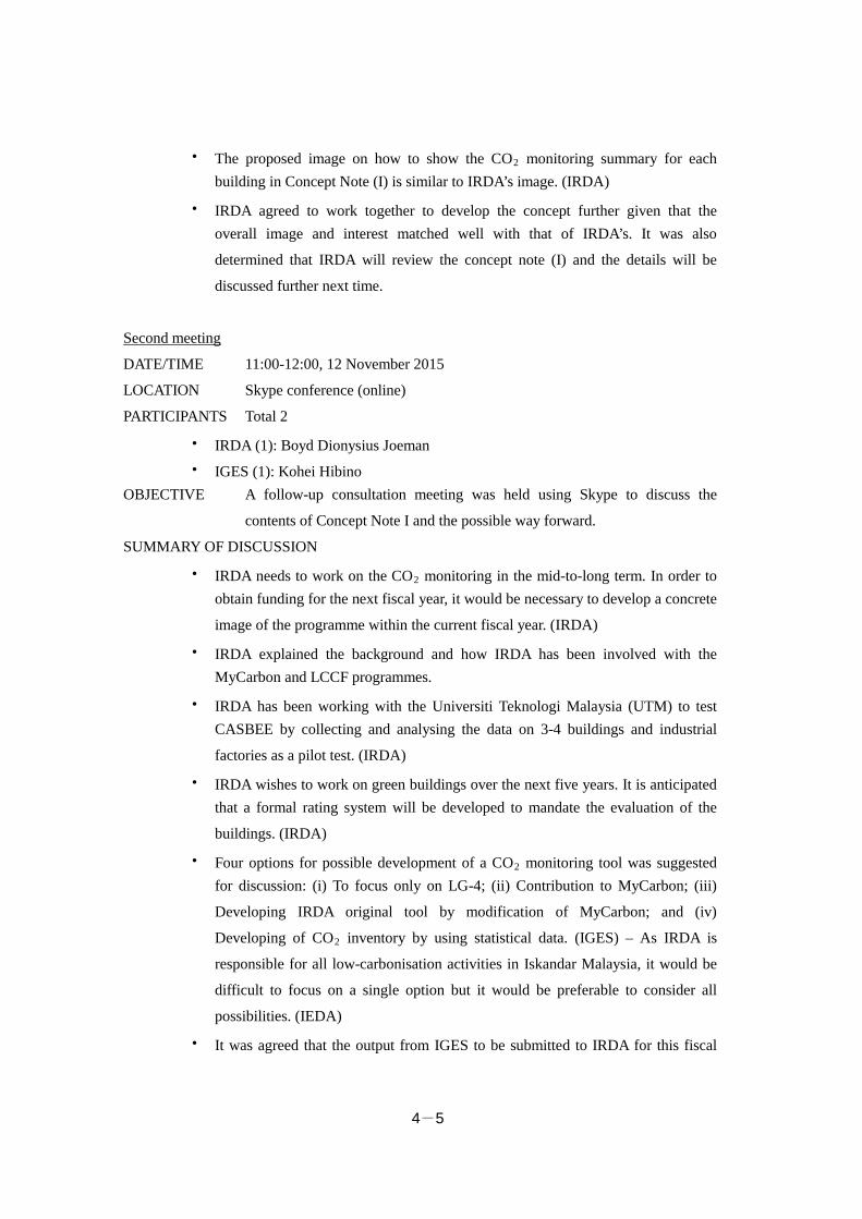
4-5
・ The proposed image on how to show the CO2 monitoring summary for each building in Concept Note (I) is similar to IRDA’s image. (IRDA)
・ IRDA agreed to work together to develop the concept further given that the overall image and interest matched well with that of IRDA’s. It was also
determined that IRDA will review the concept note (I) and the details will be
discussed further next time.
Second meeting
DATE/TIME 11:00-12:00, 12 November 2015
LOCATION Skype conference (online)
PARTICIPANTS Total 2
・ IRDA (1): Boyd Dionysius Joeman
・ IGES (1): Kohei Hibino OBJECTIVE A follow-up consultation meeting was held using Skype to discuss the
contents of Concept Note I and the possible way forward.
SUMMARY OF DISCUSSION
・ IRDA needs to work on the CO2 monitoring in the mid-to-long term. In order to obtain funding for the next fiscal year, it would be necessary to develop a concrete
image of the programme within the current fiscal year. (IRDA)
・ IRDA explained the background and how IRDA has been involved with the MyCarbon and LCCF programmes.
・ IRDA has been working with the Universiti Teknologi Malaysia (UTM) to test CASBEE by collecting and analysing the data on 3-4 buildings and industrial
factories as a pilot test. (IRDA)
・ IRDA wishes to work on green buildings over the next five years. It is anticipated that a formal rating system will be developed to mandate the evaluation of the
buildings. (IRDA)
・ Four options for possible development of a CO2 monitoring tool was suggested for discussion: (i) To focus only on LG-4; (ii) Contribution to MyCarbon; (iii)
Developing IRDA original tool by modification of MyCarbon; and (iv)
Developing of CO2 inventory by using statistical data. (IGES) – As IRDA is
responsible for all low-carbonisation activities in Iskandar Malaysia, it would be
difficult to focus on a single option but it would be preferable to consider all
possibilities. (IEDA)
・ It was agreed that the output from IGES to be submitted to IRDA for this fiscal
4-6
year would be in a form of draft proposal document that could possibly be used
for applying for a project in the next fiscal year.
Third meeting
DATE/TIME 9:00-14:30, 14 December 2015
LOCATION IRDA Headquarter
PARTICIPANTS Total 4
・ IRDA (3): Choo Hui Hong, Shahrinaz Binti Maamor, Muhammad Fahim Mohd Shaini
・ IGES (1): Kohei Hibino OBJECTIVE A follow-up consultation meeting was held at IRDA to discuss the possible
development and way forward of CO2 monitoring in Iskandar Malaysia
using Concept Note II (Annex 4-2).
SUMMARY OF DISCUSSION
・ The status and challenges of existing CO2 monitoring of buildings and green building programmes in Malaysia was explained. (IRDA)
・ IRDA needs to develop an original new system that can enhance CO2 monitoring in Iskandar Malaysia as the existing programmes have some problems in their
wider application.
・ IRDA is currently considering introducing three relevant programmes: (IRDA) Global Protocol for Community-Scale Greenhouse Gas Emission Inventories
(GPC)5
Building Energy Monitoring and Reporting System (EMRS)6
Comprehensive Assessment System for Built Environment Efficiency
(CASBEE)
・ As the next step, it was agreed that IRDA will review the contents of the concept note and IGES will be developing a draft prototype of the CO2 calculator.
(4) Compilation of report
Background and outline
The results of the third meeting with IRDA (on 14 December 2015) revealed that one of the
emerging programmes (i.e., EMRS) overlaps with the scope of the concept notes. After
5 Global Protocol for Community-Scale Greenhouse Gas Emission Inventories (GPC) was developed by the partnership among World Resources Institute, C40 Cities Climate Leadership Group and ICLEI: http://www.ghgprotocol.org/city-accounting 6 A CO2 monitoring program of buildings targeting the 5 local councils in Iskandar Malaysia.
4-7
consultation with IRDA, it was decided to abandon the developing of a concept note and the
prototype CO2 calculator as an output for the current fiscal year but instead to compile a report
that summarises the status and challenges of CO2 monitoring and green building programmes in
Malaysia and discusses the potential way forward of development including linkage with JCM.
The outline of the report which was submitted to IRDA (A4, WORD file, 12p., English: Annex
4-3) is as follows:
Status and challenges
Several government agencies and private sectors in Malaysia have developed either a building
rating system and/or CO2 monitoring programme for buildings. There are many overlaps in the
functions of these programmes and mutual collaboration seems to be limited. Some challenges
were also identified such as: the data entry formats have too many items or are not user-friendly;
users are asked to calculate CO2 emissions by themselves; the user fees are expensive, etc. This
suggested that there are no existing programmes that are readily useful for IRDA to implement
and promulgate the CO2 monitoring and/or environment performance rating of buildings in
Iskandar Malaysia.
IRDA is currently considering introducing new programmes: GPC, EMRS and CASBEE. These
can potentially fulfil the needs of IRDA but there are some challenges such as how to effectively
link these programs and make best use of the limited resources.
Recommendations and potential linkage with JCM
The following recommendations were incorporated into the report as one way of addressing the
gaps and challenges: (i) Coordination with other existing programmes and tools for mutual
sharing; (ii) Mutual linkage and coordination of methodologies among IRDA programmes; (iii)
Modification to ensure simple and user-friendly format; (iv) Incorporation of user perspectives;
and (v) Comparison with and learning from other similar tools.
Once the environment performance rating or CO2 monitoring of buildings are mandatory
requirements in Iskandar Malaysia, it is expected that the chances for identifying JCM projects
from building sectors will be increased. Future possible expansion includes: studying the
feasibility of applying EMRS and/or CASBEE for industrial factories in Iskandar Malaysia; and
developing model cases that jointly apply these programmes and JCM schemes to buildings in
Iskandar Malaysia.
4-8
(5) Information gathering and coordination work by local consultant
Information gathering and coordination work was partly consigned to a local consultant who is
knowledgeable in waste management issues in Malaysia in order to effectively gather
information related to waste management in Malaysia, facilitate liaison and coordination with
relevant local entities, and to smoothly organizing the workshops in Malaysia. The result of this
information gathering work was reflected in Chapters 2 and 3.
Consignee
SoluWaste Management Consultants located
19, Jalan Damai Perdana 1/2B, Bandar Damai Perdana,
56000 Kuala Lumpur, Malaysia
Person in charge: Dr. Theng Lee Chong (Principal Consultant)
Information gathering work
Gathering of basic information on the status and challenges of waste management in Malaysia
and/or Iskandar region was tasked to the local consultant. A list of required information (Table 1)
was sent to the contracted local consultant and the information gathering was tasked to the extent
possible. The information obtained was shared periodically with the co-proposer of this project
and reflected in the ongoing FS for the waste management sector. Some of the non-disclosed
information sources were abandoned for collection.
Table 1. List of required information which was tasked to the local consultant for collection.
1. Municipal Solid Waste (MSW) (1) Basic data related to waste
・ Amount of waste generated (household waste, commercial waste, etc.) ・ Amount of waste disposed (transition data, household waste, commercial waste, etc.) ・ Result of analysis of waste characteristics ・ Coverage area of waste collection ・ Collection and transportation method ・ Treatment methods (landfill, recycling, others by ratio and/or weight)
(2) Cost of waste management ・ Governmental budget allocation for waste management (Pasir Gudang, Johor state, or
federal government) ・ Waste collection fee, transportation fee, processing fee ・ How the fees are being collected ・ Landfill cost (tipping fees, how the tipping fees are determined, etc.) ・ Which organisation has the authority to determine these cost and how they are
determined
4-9
・ Availability of subsidies (3) Status of landfill sites
・ Locations (on map) ・ Status of acceptance (tons/year) ・ Capacity (total and remaining; predicted years to become full) ・ Operating organisation or company (public or private?) ・ Responsible authority (city/state/federal?) ・ Challenges or issues (if any)
(4) Status of waste segregation (2 + 1 programme) ・ Status (what they are doing, how things are, challenges, etc.) ・ Official plans or strategy documents ・ Role of stakeholders (e.g., SW Corp, municipalities)
(5) Licensing of waste management ・ Responsible authority (where to apply for licensing) ・ How to apply for licensing ・ List of licensed operators (name, address, type of facility, e.g., RDF, etc.)
(6) Status of landfill rehabilitation: ・ Implementation cases (location, quantity, treatment method, what for?) ・ Availability of subsidies
(7) Waste-to-Energy application ・ Necessary procedure to gain permission for construction/operation of waste-to-energy
facility (from State/Local council) ・ Necessary procedure to apply for FIT to SEDA ・ Plans for waste-to-energy facility construction in Pasir Gudang ・ Status of waste-to-energy facility tender in Kuala Lumpur
(8) Future plans of waste management ・ Targets and plans (amount of waste generated, recycling rate, etc.) ・ Presence of absence of waste segregation and collection plan ・ Presence of absence of waste treatment facility development ・ Presence of absence of (existing) facility improvement plan
(9) Other ・ Role of state and local municipalities on MSW after Act672 has been enacted ・ Legal basis that is prohibiting the transportation of MSW among municipalities ・ Process and specifications of international bidding of incineration facility
2. Scheduled waste (SW) (1) Status
・ Types of separation of SW ・ How is the SW being collected and treated after collection ・ Status of SW generated from each state ・ Information of designated SW operating company in each state ・ Availability of power generating facility in the incineration of SW and its specification
if available (2) Cost of treatment of the scheduled waste
4-10
・ Collection, transportation, detoxification treatment, landfill, etc.
Coordination work
The following coordination work was tasked to the local consultant as part of the assistance to
the FS and organisation of workshops in Malaysia:
・ Liaison and coordination with relevant local organisations, meetings and site visits Meeting with KeTTHA (6/29; location: KeTTHA)
Meeting with the Solid Waste Management and Public Cleansing Corporation (SW
Corp) (8/25; location: SW Corp Johor)
Site visit to Tanjung Langsat landfill site (8/24)
Site visit to Seelong landfill site(8/24)
・ Organising a workshop (preparation and on-site logistics) Second workshop in Iskandar region (Reporting workshop) (1/21; location: Grand
Paragon Johor Bahru)
Deliverable report
The results of the above mentioned information gathering and coordination work were shared
periodically with the co-proposer of this project and reflected in the ongoing FS and eventually
compiled into a deliverable report (A4, WORD file, 39p., English: Annex 4-4).
4.1.5 Potential of Institutionalisation and Linkage with JCM (1) Potential and challenges toward institutionalisation
The three programmes which IRDA is currently considering introducing (i.e., EMRS, CASBEE,
GPC) are all anticipated to be carried forward on a project basis taking several years. From that
perspective, it is highly likely that these programmes will be institutionalised. On the other hand,
it is considered that wide dissemination, continuation and well-established operation of the said
programmes will require some ingenuity and improvement efforts. The other challenge may be
on how to achieve effective collaboration among these programmes with limited resources and
by making the best use of the common areas that are available in these programmes.
(2) Relevance and potential application to JCM
CASBEE and EMRS currently under consideration by IRDA are anticipated to start by targeting
government buildings and gradually expanding their targets to commercial buildings. In addition,
4-11
it is also suggested that they will start from voluntary participation but eventually be shifted to
mandatory requirements. The number of participating buildings may be limited by voluntary
participation but this is expected to increase if it becomes compulsory. This will likely increase
the need of advanced low-carbon technologies and hence increase the likelihood of identifying
candidate JCM projects.
Prospective future developments in collaboration with the JCM include: (i) assessing the
feasibility to apply the building rating system and/or the CO2 monitoring programme, which
IRDA is expecting to introduce, to industrial factories, and (ii) testing the JCM candidate
buildings (if identified) by using the said building rating system and/or CO2 monitoring
programmes.
As IRDA is the leading agency on the low-carbonisation of Iskandar Malaysia and is involved in
several low-carbonisation projects, it is suggested that close ties be kept with IRDA through JCM
activities thereby raising the potential of identifying JCM projects in Iskandar Malaysia. For
example, the data that IRDA will be collecting from the CO2 monitoring and/or the building
evaluation programs can be analysed and effectively used to identify buildings that have high
potential of CO2 reduction. If the owner of such building is keen to enhance the environment
performance of the building, IRDA could introduce the JCM scheme and mediate the application
to JCM.
4.2 Organising Workshops 4.2.1 Summary of the Section In order to share information and understanding on the contents and progress of the study and to
ensure smooth operation of the work, the current JCM city-to-city collaboration FS is expected
to organise two workshops, one at the beginning of the study, and the other one at the end of the
study, in both the Japanese host municipality (i.e., Kitakyushu City) and the local host
municipality (i.e., Iskandar Malaysia), respectively.
Regarding the workshop in Japan, the first workshop (kick-off workshop) could not be organised
in Kitakyushu City for a variety of reasons including a conflict of schedule among participants.
Therefore the workshop was held in conjunction with the first progress reporting meeting in
Tokyo on 13 May 2015. The second workshop (reporting workshop) was organised in
Kitakyushu City on 16 December 2015.
4-12
For the workshop in Iskandar Malaysia, it was considered to be premature to organise a
workshop at a time when the FS started in early 2015 given that the prospects of a bilateral
agreement on JCM were not clear and relationship building with relevant agencies was not
sufficient at that time. So an individual meeting (part of it was joint) was organised with relevant
agencies, respectively, in compensation for the first workshop (kick-off workshop). The second
workshop (reporting workshop) was organised in a workshop style by inviting relevant
organisations in Johor State on 21 January 2016. In the reporting workshop in Johor State, active
discussion took place which suggested interest and expectation in the JCM.
4.2.2 Workshop in the Japanese Host Municipality Two workshops were planned to be held in Kitakyushu City, but the first workshop (kick-off
workshop) could not be organised in the City due to conflict of schedule. The first workshop was
held in conjunction with the first progress reporting meeting in Tokyo on 13 May 2015 upon
getting consent from the Ministry of the Environment. The second workshop (reporting
workshop) which was to share the progress of the study was organised in Kitakyushu City on 16
December 2015.
(1) First workshop in Japan (Kick-off workshop)
DATE/TIME 15:00-16:00, 13 May 2015
LOCATION 2nd Laurel Building, Tokyo
PARTICIPANTS Total 7
・ Ministry of the Environment (3): Teppei Yamaga, Tomoki Uematsu, Shuichi Ozawa
・ Joint-business partners (6): Kitakyushu City (Kengo Ishida, Junichi Sono, Hironori Sakai), NTT DATA Institute of Management Consulting (Motoshi
Muraoka), Amita Corporation (Teruo Yamazaki), IGES (Shiko Hayashi).
SUMMARY OF DISCUSSION
Overall Matters
・ As the relevant authority is concentrated in the Johor State and not in Pasir Gudang City, the basic stance will be to conduct the study in line with the LCSBP
of IRDA and to share information and progress with Johor State periodically.
(Kitakyushu City)
Energy Sector (Annex 4-5)
・ The study will focus on energy saving and exhaust heat recovery in industrial factories and aims to identify candidate projects.

4-13
・ Regarding energy savings, the target could be expanded to include Japanese affiliated companies. (Ministry of the Environment)
Waste Management Sector (Annex 4-6)
・ The feasibility study has been ongoing for several years using another funding scheme of the Ministry of the Environment. If the project proceeds smoothly, a
recycling factory for scheduled waste (SW) will be established in Selangor State.
・ A feasibility study on a similar recycling project will be conducted in Iskandar Malaysia.
Support for Institutionalisation of Relevant Policies (Annex 4-7)
・ Information gathering on relevant laws and regulations will be conducted by consigning the work to a local consultant.
・ Relevant agencies at federal and state levels will visit Kitakyushu City and a relationship will be built for further study and implementation of projects as well
as to find out the need to institutionalise relevant policies.
(2) Second workshop in Japan (Reporting workshop)
DATE/TIME 15:20-15:50, 16 December 2015
LOCATION International Village Center, Kitakyushu City
PARTICIPANTS Total 12
・ Kitakyushu City (3): Kengo Ishida, Hironori Sakai, Shuji Matsumoto
・ NTT DATA Institute of Management Consulting (3): Motoshi Muraoka, Tomomi Hoshiko, Maria Yamakawa
・ Amita Corporation (3): Katsuhiko Sugie, Hiroshi Mekaru, Teruo Yamazaki
・ IGES (3): Yatsuka Kataoka, Shiko Hayashi, Kohei Hibino SUMMARY OF DISCUSSION
Energy Sector (Annex 4-8)
・ Three companies on the industrial estate in Pasir Gudang City (i.e., chemical factory B, petrochemical plant A, petrochemical plant B) are interested in
introducing low-carbon systems using the JCM funding scheme.
Waste Management Sector (Annex 4-9)
・ In the recycling project of scheduled waste (SW), a hearing survey of the SW operating company which is responsible for SW collection on an industrial estate
in Pasir Gudang and a sampling survey of SW revealed that there are about
300-400 tons/month of SW generated and that the component is suited as raw
material for cement.
4-14
・ In the waste-to-energy project, analysis of existing data (2014) and the analysis of waste characteristics of Seelong landfill site revealed that municipal waste
contains much plastic and is high in calories. The feasibility of the project seemed
to be high considering the situation of the Feed-in-tariff (FIT) in Malaysia, so a
further feasibility study for commercialisation of the project will be conducted
with the engineering company.
Support for Institutionalisation of Relevant Policies (Annex 4-10)
・ A study and consultation with IRDA has been undertaken with an aim to develop a CO2 monitoring programme for buildings in Iskandar Malaysia. The tentative
plan was to compile a concept note and to develop a prototype CO2 calculator.
However, it revealed that the contents of the concept note overlapped with the
other incoming programme proposal and thus requires some coordination.
4.2.3 Workshop in the Local Host Municipality As for the workshop in Iskandar Malaysia, individual meetings (part of them were joint) were
organised with relevant agencies, respectively, in compensation for the first workshop (kick-off
workshop). The second workshop (reporting workshop) was organised in Johor State on 21
January 2016. The workshop was organised by inviting relevant federal agencies, relevant
divisions of Johor State and Local Councils, IRDA and other local organisations. The progress of
each FS was presented and discussion took place.
(1) First workshop in Malaysia (Kick-off workshop)
At the time when the FS started in early 2015, the prospective of bilateral agreement on JCM
was not clear and the relationship building with relevant agencies was not sufficient. So
individual meetings (part of them joint) were held by visiting following relevant agencies,
respectively, to explain about the city-to-city collaboration FS and the potential future
collaborations.
・ KeTTHA
・ Johor Economic Planning Unit (UPEN)
・ Johor Department of Environment (DOE)
・ UTM
・ IRDA
I. Individual meeting with KeTTHA
DATE/TIME 11:30-12:30, 29 June 2015
4-15
LOCATION KeTTHA
PARTICIPANTS Total 8
・ KeTTHA (3): Rosma Wati binti Tahir (Principle Assistant Secretary), Hazrey Tomyang (Principal Assistant Secretary (Regulatory), Green Technology Sector),
Law Yen Yang (Assistant Secretary, Sustainable Energy Division))
・ Kitakyushu City side (4): Kitakyushu City (Kengo Ishida, Hironori Sakai), IGES (Shiko Hayashi, Kohei Hibino).
・ Other (1): Theng Lee Chong (local consultant) OBJECTIVE
It was anticipated that it would be necessary to get permits and approvals from the
responsible authorities when it comes to introducing energy or waste management
related low-carbon systems. Thus, in order to correctly understand which agencies are
responsible for what kind of permits and to obtain reliable connection for future
possible consultation when the project takes shape, KeTTHA was visited as the lead
government agency responsible for energy policies.
SUMMARY OF DISCUSSION
Kitakyushu City explained the background of collaborative activities in Iskandar
Malaysia and on the city-to-city collaboration FS, and discussion took place as
follows:
Relevant permits and point of contact
・ KeTTHA is responsible for establishment of power plants and PV panels but installation of cogeneration system is up to each factory/company and does not
require any permits from the central government.
・ However, licensing for cogeneration instalment needs to be obtained from the Energy Commission (obtained the contact details).
・ The Sustainable Energy Development Authority (SEDA) is responsible for FIT system, while the Malaysian Green Technology Corporation is responsible for the
Green Technology Finance Scheme.
・ Regarding installation of PV panels, SEDA needs to be contacted (obtained the contact details).
Appropriate collaboration partners in Iskandar Malaysia
・ IRDA Local Councils are responsible for implementation of LCSBP in Iskandar Malaysia and there is no financial supporting mechanism from the federal
government.
4-16
・ IRDA is responsible for overseeing the five Local Councils in Iskandar Malaysia and recognises the priorities and challenges of each Local Council, so it would be
appropriate to approach IRDA first. For actual implementation and/or monitoring
of each programme, each respective Local Council could be approached through
IRDA.
・ For necessary licensing and/or implementation of the project, each Local Council has authority so a respective Local Council should be approached. Consultation at
the state level is not necessary in particular but it was suggested to consult with
Johor State for any activities that have wider implications.
・ There are no divisions that deal with energy savings (such as cogeneration) or energy related matters in Johor State.
・ Local Councils have the right to submit proposals on external funding directly without getting permissions from the federal government.
・ Constructing a factory could be implemented under the authority of Local Councils and does not require application to the federal government.
Renewable energy
・ Among the five renewable energies (i.e., PV, biomass, biogas, small-scale hydroelectric power generation, geothermal power generation), Malaysian
government would like to promote biomass and biogas. However, due to
uneasiness of installation of the systems, PV which is easy to install has the
highest percentage (60%). The overall electricity generated from the renewable
energies in Malaysia as of now is 290MW.
II. Joint meeting with UPEN, Johor DOE, IRDA and UTM
DATE/TIME 9:30-11:00, 1 July 2015
LOCATION UPEN, Johor State Government Office
PARTICIPANTS Total 11
・ UPEN (4): Hj. Mohammed Ridha (Deputy Director), Mohd Gadaffie Abd Aziz (Principal Assistant Director), Gurpreet Singh Dhaliwal, Intan Farha Hanina
Ahmad
・ Johor DOE (1): Kamarudin Abdul Rahman
・ IRDA (2): Boyd Dionysius Joeman (Acting Head, Environment), Choo Hui Hong
・ UTM (1): Chau Loon Wai
・ Kitakyushu City side (3): Kitakyushu City (Kengo Ishida), IGES (Shiko Hayashi, Kohei Hibino).
4-17
OBJECTIVE
The main target of the city-to-city collaboration FS was Pasir Gudang City but it was
anticipated that acceptance by or coordination with Johor State will be necessary when
introducing energy or waste management systems. So in order to develop a basis for
cooperation and to gain understanding on the city-to-city collaboration FS, UPEN was
visited. Other relevant agencies and institutions including Johor DOE, IRDA and UTM
also participated in the meeting.
SUMMARY OF DISCUSSION
In the meeting, UPEN, Johor DOE and UTM made presentations or statements to
explain their ongoing activities. Kitakyushu City then explained the background to
collaborative activities in Iskandar Malaysia and the city-to-city collaboration FS
before moving on to discussions.
Possibility for collaboration
・ Johor State is willing to support activities by Kitakyushu City and it is appropriate to approach the state level. (UPEN)
・ The bilateral agreement on JCM has not yet been signed between the two governments. Under such conditions, IRDA will be able to support the project
until the FS stage but it will be difficult to do so when the project moves on to the
implementation stage. (IRDA)
・ IRDA is interested in the Industrial Symbiosis concept and it will become the first case in Malaysia if that could be realised in Pasir Gudang. (IRDA)
Jurisdiction and point of contact
・ The two industrial estates in Pasir Gudang are under the jurisdiction of Johor Corporation which is a government affiliated company. (UPEN)
・ The Local Councils are not involved in the management of scheduled waste and DOE has all the control competence and information. (DOE)
・ Regarding establishment of processing facility for cement raw materials, it was suggested to contact the DOE headquarter. (DOE)
・ Johor DOE will be able to respond to information gathering and hearing related to scheduled waste (obtain the contact details). (DOE)
III. Individual meeting with IRDA
DATE/TIME 10:00-12:00, 2 July 2015
LOCATION IRDA
4-18
PARTICIPANTS Total 8
・ IRDA (3): Boyd Dionysius Joeman, Choo Hui Hong, Faisal Ibrahim (Vice President, Planning and Compliance), Muhammad Fadly Muhammad Nor
・ JICA expert(1): Koichi Okabe
・ Kitakyushu City side (4): Kitakyushu City (Kengo Ishida, Hironori Sakai), IGES (Shiko Hayashi, Kohei Hibino).
OBJECTIVE
As the leading agency for sustainable development and low-carbonisation of Iskandar
Malaysia, IRDA was visited to explain about the city-to-city collaboration FS and to
discuss about potential future collaboration.
SUMMARY OF DISCUSSION
The meeting started with a presentation on recent activities by IRDA followed by an
explanation of the city-to-city collaboration FS by Kitakyushu City. There was then an
explanation about the ongoing public invitation on the construction of a waste
management facility which IRDA is calling for, followed by questions and answers. An
outline is described below.
Background, objectives and roles
・ All landfill sites in Pasir Gudang City are full and the “2+1” waste separation will begin soon, so construction and operation of a municipal waste management
facility is urgently needed.
・ A call for proposals on the construction of a waste treatment facility in Pasir Gudang City is currently open to private companies based on the Integrated Solid
Waste Management Blueprint (2010). The Kitakyushu City team was invited to
consider developing and submitting a proposal on this as part of the current FS
(necessary documents for proposal were obtained).
・ The role of IRDA in this project is only coordination. The Johor State government (i.e., UPEN) has the discretion to select vendors as well as other final decisions.
IRDA will be conducting public offerings, mediating the proposals with the State,
and mediating with the federal agencies when any problem occurs.
Targets and conditions
・ The target waste for treatment is mixed waste from households, waste generated from landfill rehabilitation, commercial food waste from hotels, etc., and sewage
sludge.
・ The by-products (i.e., water, gas) that will be generated in the process can be sold
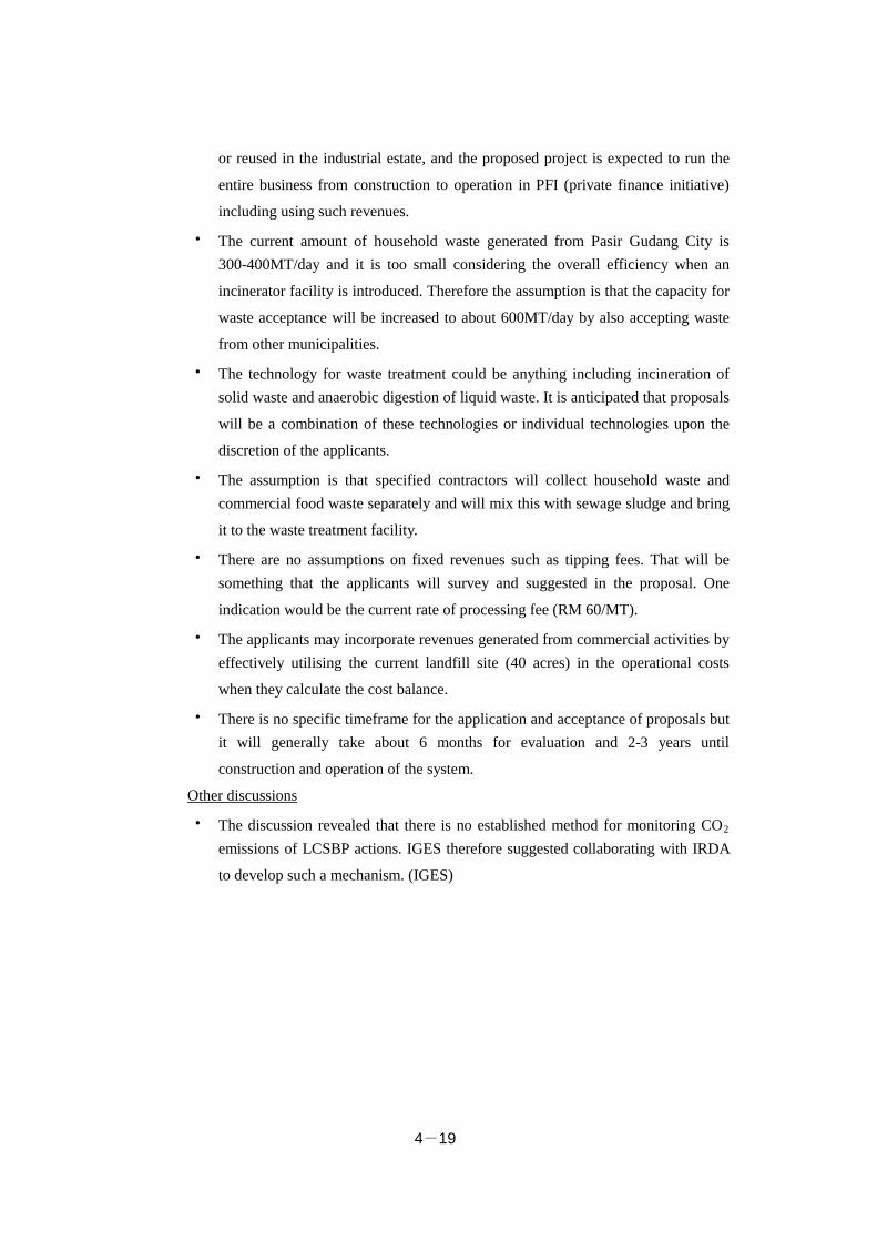
4-19
or reused in the industrial estate, and the proposed project is expected to run the
entire business from construction to operation in PFI (private finance initiative)
including using such revenues.
・ The current amount of household waste generated from Pasir Gudang City is 300-400MT/day and it is too small considering the overall efficiency when an
incinerator facility is introduced. Therefore the assumption is that the capacity for
waste acceptance will be increased to about 600MT/day by also accepting waste
from other municipalities.
・ The technology for waste treatment could be anything including incineration of solid waste and anaerobic digestion of liquid waste. It is anticipated that proposals
will be a combination of these technologies or individual technologies upon the
discretion of the applicants.
・ The assumption is that specified contractors will collect household waste and commercial food waste separately and will mix this with sewage sludge and bring
it to the waste treatment facility.
・ There are no assumptions on fixed revenues such as tipping fees. That will be something that the applicants will survey and suggested in the proposal. One
indication would be the current rate of processing fee (RM 60/MT).
・ The applicants may incorporate revenues generated from commercial activities by effectively utilising the current landfill site (40 acres) in the operational costs
when they calculate the cost balance.
・ There is no specific timeframe for the application and acceptance of proposals but it will generally take about 6 months for evaluation and 2-3 years until
construction and operation of the system.
Other discussions
・ The discussion revealed that there is no established method for monitoring CO2 emissions of LCSBP actions. IGES therefore suggested collaborating with IRDA
to develop such a mechanism. (IGES)
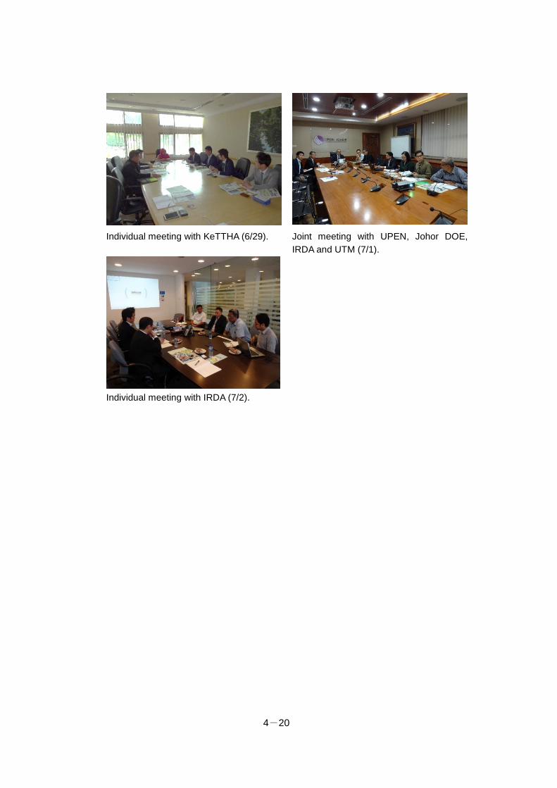
4-20
Individual meeting with KeTTHA (6/29). Joint meeting with UPEN, Johor DOE, IRDA and UTM (7/1).
Individual meeting with IRDA (7/2).
4-21
(2) Second workshop in Malaysia (Reporting workshop)
DATE/TIME 9:20-12:00, 21 January 2016
LOCATION Grand Paragon Hotel Johor Bahru
PARTICIPANTS Total 38
・ IRDA (7): Boyd Dionysius Joeman, others
・ Malaysian government (4): SW Corp (1), Johor DOE (1), Department of Town and Country Planning, Ministry of Housing and Local Government (JPBD: 1),
Department of Irrigation and Drainage Ministry of Agriculture (JPS: 1)
・ Local Councils (9): Johor Bahru Tengah Municipal Council (MPJBT: 6), Pasir Gudang Municipal Council (MPPG: 1), Kulai Municipal Council (MPK: 1),
District Council of Pontian (MDP: 1)
・ Japan side (7): Kitakyushu City (Kengo Ishida, Hironori Sakai Shuji Matsumoto), NTT Data Institute of Management Consulting (Motoshi Muraoka, Maria
Yamakawa), Amita Corporation (Eiichi Yamato), IGES (Kohei Hibino)
・ Other local participants (11): UTM (5), Local companies (4), Local consultant (1), Translator (1)
OBJECTIVE
The workshop was organised by inviting relevant local stakeholders and sharing the
results and progress of the city-to-city collaboration FS conducted in Iskandar
Malaysia and to discuss the potential way forward.
AGENDA
1. Opening remarks
2. Iskandar Malaysia: Low Carbon Society Blueprint Implementation & Updates
(IRDA) (Annex 4-11)
3. Exhaust Heat Recovery, Introduction of Dispersed Power System and Saving
Energy in Industrial Estate (NTT Data Institute of Management Consulting)
(Annex 4-12)
4. General Waste Power Generation Business (NTT Data Institute of Management
Consulting) (Annex 4-12)
5. Promotion of Low-Carbon Type Industrial Waste Recycling (Amita Corporation)
6. Low Carbon Development Funding Schemes (IGES) (Annex 4-13)
7. Open Discussion
SUMMARY OF DISCUSSION
Questions concerning results of FS
・ Q. What is the level of energy saving in the industrial estates of Iskandar Malaysia
4-22
compared to that of other countries? – A. It depends on when the industrial estates
were established. Most of the factories that were visited in Iskandar Malaysia
were about 20 years or order and had enough room to reduce energy use.
・ Q. The cost estimates of the tipping fees seem to be too low. Are the tipping fees based on the same system used in Japan/Germany? – A. The system used for
calculation is the same as in Japan/Germany. The presented tipping fees are very
preliminary calculations based on assumptions and they require detailed analysis.
・ Q. Background details of the figures are not available in the cost figures shown on the incinerator. A. The figures are from the engineering company and the details
are not clear. The heat recovery system may not be incorporated in the calculation.
Questions concerning JCM
・ Q. Who pays for the equipment and how much do they need to pay? – A. The maximum amount of the subsidy is 50% of the initial investment cost of the
applied system and the remaining 50% or more should be invested by the local
company.
・ Q. What is the criteria to apply for the scheme? – A. There are no specific limitations for application but there are many check points, such as the paying
capacity and the ability to operate the system.
・ Q. What is the benefit of JCM to the companies? – A. The merit of JCM is that it makes economic sense. The important benefit of JCM is not just the reduced
initial investment cost but it also reduces the running cost hence it shortens the
repayment period.
・ Q. What is the duration of the scheme? – A. The project needs to be completed within three years and the owner who introduced the system has an obligation to
conduct monitoring for the length of legal depreciation period of the installed
system.
・ Q. What could be the alternatives for interested parties if the bilateral agreement is not signed by both governments? – A. There are no other alternatives but to
explore other funding schemes.
・ Q. Is the scheme a grant or loan, and is it applicable for the stage of maintenance and operation? – A. The scheme is a grant and only applicable for the initial
investment costs.
・ Q. Does the system to be installed need to be a Japanese product? – A. It is not restricted to a Japanese system.
・ Q. Is it necessary to establish an international consortium? – A. Following the
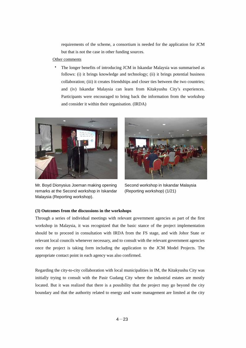
4-23
requirements of the scheme, a consortium is needed for the application for JCM
but that is not the case in other funding sources.
Other comments
・ The longer benefits of introducing JCM in Iskandar Malaysia was summarised as follows: (i) it brings knowledge and technology; (ii) it brings potential business
collaboration; (iii) it creates friendships and closer ties between the two countries;
and (iv) Iskandar Malaysia can learn from Kitakyushu City’s experiences.
Participants were encouraged to bring back the information from the workshop
and consider it within their organisation. (IRDA)
Mr. Boyd Dionysius Joeman making opening remarks at the Second workshop in Iskandar Malaysia (Reporting workshop).
Second workshop in Iskandar Malaysia (Reporting workshop) (1/21)
(3) Outcomes from the discussions in the workshops
Through a series of individual meetings with relevant government agencies as part of the first
workshop in Malaysia, it was recognized that the basic stance of the project implementation
should be to proceed in consultation with IRDA from the FS stage, and with Johor State or
relevant local councils whenever necessary, and to consult with the relevant government agencies
once the project is taking form including the application to the JCM Model Projects. The
appropriate contact point in each agency was also confirmed.
Regarding the city-to-city collaboration with local municipalities in IM, the Kitakyushu City was
initially trying to consult with the Pasir Gudang City where the industrial estates are mostly
located. But it was realized that there is a possibility that the project may go beyond the city
boundary and that the authority related to energy and waste management are limited at the city

4-24
level, thus it was suggested that it would be most appropriate to partner with IRDA which
manages the entire IM.
The second workshop in Malaysia indicated that there is a high interest and expectations to JCM
scheme among the relevant stakeholders, thus it is expected that the JCM bilateral agreement
between the two nations will be settled at the earliest possible.