Embed Size (px)
Citation preview

Establish Your Debug Session
TRACE32 Online Help
TRACE32 Directory
TRACE32 Index
TRACE32 Debugger Getting Started ..............................................................................................
Establish Your Debug Session .................................................................................................... 1
Establish your Debug Session .................................................................................................. 4
Key TRACE32 Setup Commands 4
The PER.view/PER.Set Command 4
The Data.LOAD Command 6
Debug Scenarios 9
Establish the Debug Communication ....................................................................................... 11
Debug Scenario 1 ....................................................................................................................... 17
Onchip/NOR Flash Programming 18
The Flash Programming File 18
On-chip Flash Programming 19
Off-chip NOR Flash Programming 24
Configure the TRACE32 OS Awareness 35
Debug Scenario 2 ....................................................................................................................... 36
Typical Boot Sequence 36
Flash Programming (NAND/Serial/eMMC) 41
The Flash Programming File and the Debug Symbol File 41
NAND Flash Programming (non-generic NAND Flash Controller) 42
eMMC Flash Programming 54
Establish the Communication 55
Load the Debug Symbols 55
Debug Scenario 3 ....................................................................................................................... 56
Run the Boot Loader 57
Load Application (and/or OS) Code and Debug Symbols 58
Load Debug Symbols only 58
Configure the TRACE32 OS Awareness 58
Complete Setup Example 58
Debug Scenario 4 ....................................................................................................................... 59
Write a Script to Configure the Target 60
Load Application (and/or OS) Code and Debug Symbols 60
Configure the TRACE32 OS Awareness 60
Generate a Start-Up Script ........................................................................................................ 61
Establish Your Debug Session 1 ©1989-2018 Lauterbach GmbH

Write a Start-Up Script 61
Run a Start-up Script 62
Automated Start-up Scripts 63
Establish Your Debug Session 2 ©1989-2018 Lauterbach GmbH

Establish Your Debug Session
Version 16-Nov-2018
Establish Your Debug Session 3 ©1989-2018 Lauterbach GmbH

Establish your Debug Session
Before you can start debugging, the debug environment has to be set up. The necessary setup depends crucially on the debug scenario.
Key TRACE32 Setup Commands
The PER.view/PER.Set Command
A debug setup requires various configurations in core/chip related configuration registers.
The main commands to perform these configurations are:
The main command to inspect the configurations is:
PER.Set.simple <address>|<range> [%<format>] <string> Modify configuration register/on-chip peripheral
Data.Set <address>|<range> [%<format>] <string> Modify memory-mapped configuration register/on-chip peripheral
PER.view <filename> [<tree_search_item>] /SpotLight Display the configuration registers/on-chip peripherals, highlight changes
Establish Your Debug Session 4 ©1989-2018 Lauterbach GmbH

Example: Disable Watchdog
; Display “Watchdog Timer” configuration registers, highlight changes; a comma is used instead of the <filename>PER.view , "Watchdog Timer" /SpotLight
; Disable Watchdog timer by configuring Watchdog Timer Control Register; (WTCON) PER.Set.simple 0x53000000 %Long 0x0
Establish Your Debug Session 5 ©1989-2018 Lauterbach GmbH

The Data.LOAD Command
A debug setup requires to load the code to be debugged and to load the debug symbols. TRACE32 PowerView supports a wide range of compilers and compiler output formats.
To get a list of all compilers supported for your core proceed as follows:
1. Open the Processor Architecture Manual for your core.
2. Refer to the compiler list provided by this manual. The Option column lists the supported output formats.
Establish Your Debug Session 6 ©1989-2018 Lauterbach GmbH

The most important commands to load the code to be debugged and the debug symbols are:
A in-depth introduction to the Data.LOAD command is given in the chapter ”Load the Application Program” (training_hll.pdf)
Data.LOAD.<subcommand> <file> /<option> Load code and debug symbols
Data.LOAD.Binary <file> /<option> Load only code
Data.LOAD.<subcommand> <file> /NoCODE /<option> Load only debug symbols
Data.LOAD.Elf demo-flash.elf ; Load code and debug symbols from; ELF file
Data.LOAD.AIF demo.axf ; Load code and debug symbols from; AIF file
Data.LOAD.Elf * ; Load code and debug symbols from; ELF file ; open file browser to select file
Data.LOAD.Elf demo.elf /NoCODE ; Load debug symbols from ELF file
Data.LOAD.Binary my_app.bin ; Load code from binary file
Establish Your Debug Session 7 ©1989-2018 Lauterbach GmbH

The TASK.CONFIG Command
Today most applications use an operating system. TRACE32 PowerView includes a configurable target-OS debugger to provide symbolic debugging of operating systems.
Lauterbach provides ready-to-run configuration files for most common available OSes.
To get the appropriate information on your OS, proceed as follows:
1. Open the online help and deactivate the help filter.
2. Open the TRACE32 OS Awareness Manual for your operating system.
Establish Your Debug Session 8 ©1989-2018 Lauterbach GmbH

Debug Scenarios
The necessary setup for your debug session depends crucially on the debug scenario. The graphic below shows you that there are mainly four debug scenarios.
Is the softwarerunning out of flash?
Is a boot loader available?
YES NO
YES NO
Debug
Establish the communication betweenthe debugger and core(s)
Is the software running out of
Scenario 4Debug
Scenario 3
Onchip/NOR flash?
YES
Debug Scenario 1
NO
Debug Scenario 2
Establish Your Debug Session 9 ©1989-2018 Lauterbach GmbH

After the communication between the debugger and the core(s) is established, there a four debug scenarios. Each debug scenario requires a different setup.
• Debug Scenario 1
The boot loader or the application (and/or the operating system) under debug is running out of Onchip/NOR flash.
• Debug Scenario 2
The boot loader under debug is running out of a flash e.g. a NAND or serial flash.
• Debug Scenario 3
The application (and/or the operating system) under debug are running out of RAM and a ready-to-run boot loader configures the target system and especially the RAM for this debug scenario.
• Debug Scenario 4
The application (and/or the operating system) under debug are running out of RAM. The target configuration, especially the RAM configuration has to be done by TRACE32 commands, because there is no ready-to-run boot loader.
Establish Your Debug Session 10 ©1989-2018 Lauterbach GmbH

Establish the Debug Communication
1. Select the core/chip
2. Adjust the JTAG clock if required
3. Set the required options for your core/chip
4. Establish the communication
Establish Your Debug Session 11 ©1989-2018 Lauterbach GmbH

1. Select the target core/chip
Inform the debugger about the core/chip on your target, if an automatic detection of the core/chip is not possible. Wild card symbols * or ? are allowed.
SYStem.DETECT CPU Auto detection of CPU
SYStem.CPU <cpu> Select the CPU/chip
SYStem.CPU CortexR5
SYStem.CPU CortexR5*
Establish Your Debug Session 12 ©1989-2018 Lauterbach GmbH

2. Adjust the JTAG clock
The debugger uses a default JTAG clock of 10 MHz. Adjusting the JTAG clock might be necessary:
- if a fixed relation between the core clock and the JTAG clock is specified.
- if RTCK has to be used as JTAG clock for an ARM core.
SYStem.JtagClock <frequency> Select the JTAG clock
SYStem.JtagClock 1.MHz
SYStem.JtagClock 100.kHz
SYStem.JtagClock RTCK
Establish Your Debug Session 13 ©1989-2018 Lauterbach GmbH

3. Set the required options for your core/chip
Some cores/chips require additional settings before the communication can be established.
For details refer to the Processor Architecture Manual.
Additional settings
Establish Your Debug Session 14 ©1989-2018 Lauterbach GmbH

4. Establish the communication
The most common way to establish the communication between the debugger and the core(s) is Up.
If Up is selected, the following steps are performed:
- Reset of the core/chip
- Initialization of the communication between the debugger and the core(s)
- Stop of the core(s) at the reset vector
SYStem.Up Establish the communication between the debugger and the core(s)
Establish Your Debug Session 15 ©1989-2018 Lauterbach GmbH
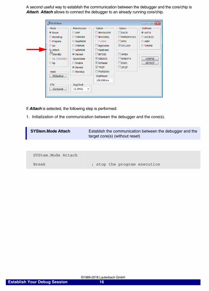
A second useful way to establish the communication between the debugger and the core/chip is Attach. Attach allows to connect the debugger to an already running core/chip.
If Attach is selected, the following step is performed:
1. Initialization of the communication between the debugger and the core(s).
SYStem.Mode Attach Establish the communication between the debugger and the target core(s) (without reset)
SYStem.Mode Attach
Break ; stop the program execution
Establish Your Debug Session 16 ©1989-2018 Lauterbach GmbH

Debug Scenario 1
The boot loader or the application (and/or the operating system) under debug is running out of the on-chip flash or out of a NOR flash device.
Is an OS used?YES NO
Establish the debug communication
Program the software to on-chip/NOR flash
(this includes the loading of the debugsymbols)
Configure the TRACE32OS Awareness for your OS
Ready for debug*
*Considering the circumstance that a process has to be started manually e.g. via a TERMinal window
Establish Your Debug Session 17 ©1989-2018 Lauterbach GmbH
Onchip/NOR Flash Programming
The debugger supports the programming of on-chip flash and off-chip NOR flash devices.
The Flash Programming File
On-chip flash and off-chip NOR flash programming allows to load any output file generated by your compiler.
NOTE: Flash programming requires that data cache is disabled for the address range covered by the FLASH.
Establish Your Debug Session 18 ©1989-2018 Lauterbach GmbH

On-chip Flash Programming
Ready-to-run scripts for most on-chip flashs can be found under ~~/demo/<architecture>/flash/<cpu>.cmm
e.g. ~~/demo/arm/flash/mk20.cmm
e.g. ~~/demo/powerpc/flash/mpc5xxx.cmm
Establish Your Debug Session 19 ©1989-2018 Lauterbach GmbH

To program the software to the on-chip flash of your processor/chip proceed as follows:
1. Start the script appropriate for your processor/chip.
2. TRACE32 PowerView informs you when all preparations are done. Please confirm that you are ready to choose the boot loader or the application to be programmed.
Establish Your Debug Session 20 ©1989-2018 Lauterbach GmbH

3. Please select the boot loader or application to be programmed.
TRACE32 PowerView informs you, that the programming is done.
If the boot loader/application is compiled with debug symbols they are automatically loaded into TRACE32 PowerView with the flash programming.
For details on the on-chip flash programming open the flash programming script.
; ~~ represents the TRACE32 installation directoryPEDIT ~~/demo/powerpc/flash/mpc5xxx.cmm
Establish Your Debug Session 21 ©1989-2018 Lauterbach GmbH

The following parameters can be used, when the flash programming script is called:
Not every script supports all parameters. The parameters relevant for your script are described in the meta data section of the script.
If you create your own start-up script for your target hardware, please call the flash programming script from there.
If you leave the flash programming script unchanged, you can always replace it with its most current version.
CPU=<cpu> If a FLASH programming script supports a CPU family, you can provide your target CPU as parameter.
PREPAREONLY Advise the FLASH programming script to prepare the FLASH programming by declaring the FLASH sectors and by linking the appropriate programming binary. The FLASH programming commands are bypassed.
DUALPORT=0|1 Disable/enable DualPort FLASH programming.For all processors/cores that allow to write to physical memory while the CPU is running a higher FLASH programming performance can be achieved by the use of DualPort FLASH Programming
Establish Your Debug Session 22 ©1989-2018 Lauterbach GmbH

The following framework can be used to call the flash programming script from your start-up script.
More details on the on-chip flash programming can be found in “Onchip/NOR FLASH Programming User’s Guide” (norflash.pdf).
…
DO <flash_script> [CPU=<cpu>] PREPAREONLY [DUALPORT=0|1]
; program file to on-chip FLASHFLASH.ReProgram ALL /EraseData.LOAD.Elf <file>FLASH.ReProgram off
; reset processor/chip; might be necessary to reset all target settings done by the flash; programming scriptSYStem.Up
; continue with start-up script…
Establish Your Debug Session 23 ©1989-2018 Lauterbach GmbH

Off-chip NOR Flash Programming
TRACE32 PowerView provides two methods to program off-chip NOR flash:
1. Tool-based programming
Tool-based programming means that the flash programming algorithm is part of the TRACE32 software. Tool-based programming is easy to configure but slow.
2. Target-controlled programming
Target-controlled flash programming means that the underlying flash programming algorithm is detached from the TRACE32 software. Target-controlled flash programming works as follows:
1. The flash algorithm is downloaded to the target RAM.
2. The programming data are downloaded to the target RAM.
3. The flash algorithm running in the target RAM programs the data to the flash devices.
Target-controlled flash programming minimizes the communication between the host and the debugger hardware. This makes target-controlled flash programming fast.
Programming off-chip NOR flash requires the following steps (see next page):
NOTE: It is recommended to start with tool-based flash programming. If this works properly you can switch to target-controlled flash programming.
Establish Your Debug Session 24 ©1989-2018 Lauterbach GmbH

Program flash
Make sure that the core has write access to the flash
Is the watchdogdisabled?
Disable watchdog
NO YES
Establish the debug communication
Is the data cachedisabled?
Disable data caches
NO YES
Has the core access to RAM?
Enable RAM access
NO YES
Do you want to use target- controlled programming?
YESNO
Establish Your Debug Session 25 ©1989-2018 Lauterbach GmbH

1. Disable Internal and External Watchdog
Example
; Display “Watchdog Timer” configuration registers, highlight changesPER.view , "Watchdog Timer" /SpotLight
; Disable Watchdog timer by configuring Watchdog Timer Control Register; (WTCON) PER.Set.simple 0x53000000 %Long 0x0
Establish Your Debug Session 26 ©1989-2018 Lauterbach GmbH

2. Disable Data Cache
The data cache has to be disabled for the address ranges of all flash devices to enable TRACE32 PowerView to read the flash status information.
Example
; Display the memory management configuration registers; highlight changesPER.view , "Core Registers,Memory Management Unit" /SpotLight
; Disable Data Cache by configuring the control register SCTLRPER.Set.simple C15:0x1 %LONG 0x550078
Establish Your Debug Session 27 ©1989-2018 Lauterbach GmbH

3. Make sure that the core has write access to the flash
NOR flash programming requires that the core has write access to the flash device(s).
The following settings in the bus configuration have to be done for each NOR flash device:
• Definition of the base address of the NOR flash device
• Definition of the size of the NOR flash device
• Definition of the bus size that is used to access the NOR flash device
• The write access has to be enabled for the NOR flash device
• Definition of the timing (number of wait states for the write access to the NOR flash device)
Use the PER.view command to check the settings in the bus configuration registers.
Establish Your Debug Session 28 ©1989-2018 Lauterbach GmbH

Example for ColdFire
Bus configuration after reset:
In order to have write access to the used off-chip NOR flash device the Address Region 0 has to be configured for the following characteristics:
• Base address 0xa0000000
• Size 16 MByte
• Bus size 16 bit
Correct bus configuration for NOR flash programming.
PER.Set <address> %<format> <value>
Data.Set <address> %<format> <value>
PER.view , /SpotLight ; Highlight all changed; configuration registers
PER.Set 0xf0000080 %Long 0xA0000031 ; ADDSEL0
PER.Set 0xf00000c0 %Long 0x00508637 ; BUSCON0
Establish Your Debug Session 29 ©1989-2018 Lauterbach GmbH

Framework for Tool-based Flash Programming
More details on the concepts of the TRACE32 NOR flash programming can be found in “Onchip/NOR FLASH Programming User’s Guide” (norflash.pdf).
If your FLASH device doesn’t provide CFI please refer to “Onchip/NOR FLASH Programming User’s Guide” (norflash.pdf) for details on the FLASH programming procedure.
FLASH.RESet Reset the FLASH declaration table
FLASH.CFI <start_address> <data_bus_width> Generate a FLASH declaration by evaluating the Common Flash Interface description inside the FLASH device.The command FLASH.CFI requires the definition of• the <start_address> of the FLASH device• the <data_bus_width> that is used by the
core to access the FLASH device
FLASH.List List the FLASH declaration table
FLASH.UNLOCK ALL Unlock the FLASH sectors
FLASH.ReProgram ALL | OFF Enable/disable the FLASH programming
Data.LOAD.<subcommand> <file> /<option> Load code and debug symbols
Establish Your Debug Session 30 ©1989-2018 Lauterbach GmbH

Example
FLASH.RESet ; Reset the FLASH declaration table
FLASH.CFI 0xa0000000 Word ; Generate a FLASH declaration via; CFI
FLASH.List ; Display the FLASH declaration; table
FLASH.UNLOCK ALL ; Unlock the FLASH device if; required; e.g. some FLASH devices are; locked after power on
FLASH.ReProgram ALL ; Enable the FLASH for programming
Data.LOAD.Elf demo.elf ; Specify the file that contains; the code and the debug symbols
FLASH.ReProgram OFF ; Program FLASH and disable ; the FLASH programming afterwards
Data.LOAD.Elf demo.elf /DIFF ; Verify the FLASH programming
IF FOUND()PRINT "Verify error after FLASH programming"
ELSEPRINT "FLASH programming completed successfully"
Establish Your Debug Session 31 ©1989-2018 Lauterbach GmbH

Framework for Target-controlled Flash Programming
FLASH.RESet Reset the FLASH declaration table
FLASH.CFI <start_address> <bus_width> /TARGET <code_range> <data_range>
Generate a FLASH declaration by evaluating the Common Flash Interface description inside the FLASH device.The command FLASH.CFI requires the definition of• the <start_address> of the FLASH device• the <data_bus_width> that is used by the
core to access the FLASH device• the target RAM location <code_range> for
the flash programming algorithm• the target RAM location <data_range> for
the flash programming data
FLASH.List List the FLASH declaration table
FLASH.UNLOCK ALL Unlock the FLASH sectors
FLASH.ReProgram ALL | OFF Enable/disable the FLASH programming
Data.LOAD.<subcommand> <file> /<option> Load code and debug symbols
Establish Your Debug Session 32 ©1989-2018 Lauterbach GmbH

Details on <code_range>
Required size for the code is size_of(file) + 32 byte
Details on <data_range>
The parameter <data_range> specifies the RAM location for the data, especially
• the <data_buffer_size> for the programming data. Recommended buffer size is 4 KByte, smaller buffer sizes are also possible. The max. buffer size is 16 KByte
• the argument buffer for the communication between TRACE32 PowerView and the programming algorithm
• the stack
<data_buffer_size> = size_of(<data_range>) - 64 byte argument buffer - 256 byte stack
Memory mapping for the <code_range> Flash programming algorithm
32 byte
Memory mapping for the <data_range>
Data buffer for data transfer between TRACE32 and flash programming algorithm<buffer_size> calculated asdescribed above
256 byte stack
64 byte argument buffer
Establish Your Debug Session 33 ©1989-2018 Lauterbach GmbH

4. Enable RAM Access
Target-controlled Flash Programming requires, that the core has access to the RAM locations specified for <code_range> and <data_range>.
If this is not the case the following settings in the bus configuration have to be done for an off-chip RAM:
• Definition of the base address of the RAM
• Definition of the size of the RAM
• Definition of the bus size that is used to access the RAM
• Definition of the timing (number of wait states for the RAM access)
Establish Your Debug Session 34 ©1989-2018 Lauterbach GmbH

Example
Configure the TRACE32 OS Awareness
Refer to “The TASK.CONFIG Command”, page 8 for details.
; reset the FLASH declaration tableFLASH.RESet
; set up the FLASH declaration for target-controlled programming; target RAM at address 0x20000000FLASH.CFI 0x0 Word /TARGET 0x20000000++0xfff 0x20001000++0xfff
; display FLASH declaration tableFLASH.List
; unlock the FLASH device if required for a power-up locked device; FLASH.UNLOCK ALL
; enable the programming for all declared FLASH devicesFLASH.ReProgram ALL
; specify the file that contains the code and the debug symbolsData.LOAD.Elf demo.elf
; program the file and disable the FLASH programming afterwardsFLASH.ReProgram OFF
; verify the FLASH contentsData.LOAD.Elf demo.elf /DIFF
IF FOUND()PRINT "Verify error after FLASH programming"
ELSEPRINT "FLASH programming completed successfully"
...
Establish Your Debug Session 35 ©1989-2018 Lauterbach GmbH

Debug Scenario 2
The boot loader under debug is running out of a flash e.g. a NAND flash.
In contrast to NOR flash, code can not be executed out of NAND or serial flash. The code has always to be copied to RAM before it can be executed.
Typical Boot Sequence
Before the setup for debug scenario 2 is described, it might be useful to have a look at a typical boot sequence. If the boot loader is running out of flash the system start-up might include the following steps:
Establish Your Debug Session 36 ©1989-2018 Lauterbach GmbH

1. Reset
At RESET the boot loader is copied from the flash to an on-chip SRAM, which is mapped to the reset vector. The boot loader starts afterwards.
Please be aware, that some core(s) require a correct ECC for this copy procedure.
Flash
Boot loader (max. 4 kByte)
Kernel image(compressed)
Second stage boot loader
Boot loader (max. 4 kByte)
Chip
On-chip SRAM
SDRAM
Copied by hardwareat RESET boot.bin
kernel.bin
0x0
Establish Your Debug Session 37 ©1989-2018 Lauterbach GmbH

2. Boot loader is running
The main task of the boot loader is to initialize the SDRAM and to copy the second stage boot loader to SDRAM. When this is done the control is passed to the second stage boot loader.
Flash
Boot loader (max. 4 kByte)
Kernel image(compressed)
Second stage boot loader
Boot loader (max. 4 kByte)
Chip
On-chip SRAM
SDRAM
Second stage boot loader
Copied by boot loaderto SDRAM
boot.bin
kernel.bin
Establish Your Debug Session 38 ©1989-2018 Lauterbach GmbH

3. Second stage boot loader is running
The main task of the second stage boot loader is to copy the kernel image to SDRAM. When this is done the control is passed to the kernel.
Flash
Boot loader (max. 4 kByte)
Kernel image(compressed)
Second stage boot loader
Chip
On-chip SRAM
SDRAM
Second stage boot loader
Copied by second stage boot loader to SDRAM
Boot loader (max. 4 kByte)
Kernel image
boot.bin
kernel.bin
Establish Your Debug Session 39 ©1989-2018 Lauterbach GmbH

Setup for Debug Scenario 2
Establish the debug communication
Load the debug symbols for the boot
Is the boot loaderalready in the
flash?
Program boot loader
NO
code to flash
YES
loader into TRACE32 PowerView
Ready for debug
Establish Your Debug Session 40 ©1989-2018 Lauterbach GmbH
Flash Programming (NAND/Serial/eMMC)
The Flash Programming File and the Debug Symbol File
Flash programming can only program binary files. Therefore two output files have to be generated by the compiler:
• A binary file (e.g. boot.bin)
• A file containing the debug symbols (e.g. boot.elf)
NOTE: Flash programming requires that data cache and MMU are disabled.
Establish Your Debug Session 41 ©1989-2018 Lauterbach GmbH

NAND Flash Programming (non-generic NAND Flash Controller)
Ready-to-run flash programming scripts for most processors/chips can be found in the directory ~~/demo/<architecture>/flash
Folder and file name convention: ~~/demo/<architecture>/flash/<cpu_name>-<prefix_of_nand_flash_code>.cmm
Get <cpu_name> from the CPU column of the list of “Supported NAND/Serial Flash Controller” on the Lauterbach home page (www.lauterbach.com) if the CONTROLLER column does not indicate generic.
If the CONTROLLER column indicates generic refer to “NAND Flash Programming (generic NAND Flash Controller)”, page 45.
Establish Your Debug Session 42 ©1989-2018 Lauterbach GmbH

Get the prefix of the <nand_flash_code> from the CODE column of the list of “Supported Flash Devices” on the Lauterbach home page (www.lauterbach.com).
Name of flash programming script here ~~/demo/arm/flash/imx31-nand2g08.cmm
Establish Your Debug Session 43 ©1989-2018 Lauterbach GmbH

To program the code to flash proceed as follows:
1. Start the script appropriate for your processor/chip and appropriate for your flash device.
2. TRACE32 PowerView informs you when all preparations are done. Please confirm that you are ready to choose the boot loader binary to be programmed.
3. Please select the boot loader to be programmed.
Detail on NAND flash programming can be found in “NAND FLASH Programming User’s Guide” (nandflash.pdf).
Establish Your Debug Session 44 ©1989-2018 Lauterbach GmbH

NAND Flash Programming (generic NAND Flash Controller)
The CONTROLLER column of the list of “Supported NAND/Serial Flash Controller” on the Lauterbach home page (www.lauterbach.com) indicates “generic”, if a processor/chip has a generic NAND flash controller.
Programming script for generic NAND flash controller have to be written by the user.
Establish Your Debug Session 45 ©1989-2018 Lauterbach GmbH

Programming a flash device with the help of a generic NAND flash controller requires the following steps:
Has the core access to RAM?
Enable RAM access
NO YES
Program flash
Prepare flash controller and flash for programming
Is the watchdogdisabled?
Disable watchdog
NO YES
Establish the debug communication
Establish Your Debug Session 46 ©1989-2018 Lauterbach GmbH

1. Prepare the NAND FLASH Controller and the NAND FLASH for Programming
Programming a flash device requires a proper initialization of the flash controller and the bus interface. The following settings might be necessary:
• Power up the flash clock domain.
• Enable the flash controller or bus.
• Configure the communication signals (clock, timing, etc.).
• Inform the flash controller about the flash device (large/small page, ECC, spare, etc.).
• Configure the flash pins if they are muxed with other functions of the processor/chip.
• Disable the write protection for the flash.
Use the PER.Set/PER.view commands for this setup.
Example for s3c2410X (ARM920T):
PER.View , "NAND Flash Controller" /SpotLight
; enable and configure NAND flash controllerPER.Set 0x4E000000 %Long 0xE030
Establish Your Debug Session 47 ©1989-2018 Lauterbach GmbH

2. Enable RAM Access
TRACE32 PowerView runs the flash programming algorithm in target RAM. It requires at least 16 KByte of RAM for this purpose.
This requires that the core has access to target RAM.
If the core has no access to target RAM, the access to target RAM has to be set up.
Correct settings in the bus configuration registers are key for the RAM access. The following settings in the bus configuration have to be done:
• Definition of the RAM base address
• Definition of the RAM size
• Definition of the bus size that is used to access the RAM
• The write access has to be enabled for the RAM
• Definition of the timing (number of wait states for the write access to the RAM)
Use the PER.Set/PER.view commands for this setup.
Establish Your Debug Session 48 ©1989-2018 Lauterbach GmbH

Example SDRAM configuration on an s3c2410X (ARM920T):
Bus configuration after reset:
Per.Set 0x48000000 %Long 0x2222D222Per.Set 0x48000004 %Long 0x00000700Per.Set 0x48000008 %Long 0x00007ff0Per.Set 0x4800000C %Long 0x00000700Per.Set 0x48000010 %Long 0x00001F4CPer.Set 0x48000014 %Long 0x00000700Per.Set 0x48000018 %Long 0x00000700Per.Set 0x4800001C %Long 0x00018005Per.Set 0x48000020 %Long 0x00018005Per.Set 0x48000024 %Long 0x008e0459Per.Set 0x48000028 %Long 0x00000032Per..Set 0x4800002C %Long 0x00000030Per..Set 0x48000030 %Long 0x00000030Per..Set 0x53000030 %Long 0x00000000
Establish Your Debug Session 49 ©1989-2018 Lauterbach GmbH

Correct bus configuration for SDRAM usage:
Establish Your Debug Session 50 ©1989-2018 Lauterbach GmbH

3. Disable internal and external watchdog
Example (ARM920T):
; Display “Watchdog Timer” configuration registers, highlight changesPER.view , "Watchdog Timer" /SpotLight
; Disable Watchdog timer by configuring Watchdog Timer Control Register; (WTCON) PER.Set.simple 0x53000000 %Long 0x0
Establish Your Debug Session 51 ©1989-2018 Lauterbach GmbH

Generic NAND Flash Programming Framework
The following commands are useful, if a generic NAND flash controller is used to program a flash. For details refer to “NAND FLASH Programming User´s Guide” (nandflash.pdf).
More details on the FLASHFILE.TARGET command:
The name of the flash programming algorithm depends on the NAND flash to be programmed (e.g. nand5608.bin for the K9F5608 NAND flash from Samsung).
Its location in the TRACE32 demo folder is defined by the number of data I/O pins between the NAND flash controller and the flash device. E.g. is there are 8 data I/O pins between the NAND flash controller and the flash device the algorithm can be found in:
~~/demo/<architecture>/flash/byte/<nand_flash_code>.bin
FLASHFILE.RESet Reset NAND flash programming to default.
FLASHFILE.CONFIG <cmd_reg> <addr_reg> <io_reg> Inform TRACE32 PowerView on the NAND flash registers
FLASHFILE.TARGET <code_range> <data_range> <file> Inform TRACE32 PowerView on all details about flash programming algorithm.
FLASHFILE.Erase <range> Erase NAND flash.
FLASHFILE.LOAD <file> <address> Program binary file to NAND flash.
Establish Your Debug Session 52 ©1989-2018 Lauterbach GmbH

This flash programming algorithm is downloaded to a target RAM when flash programming is performed. Therefore TRACE32 PowerView needs to be informed about an appropriate RAM location by the <code_range> parameter of the FLASH.TARGET program
required size for the code is size_of(file) + 32 byte
The parameter <data_range> specifies the RAM location for the data, especially
• the <data_buffer_size> for the programming data. Recommended buffer size is 4 KByte, smaller buffer sizes are also possible. The max. buffer size is 16 KByte
• the argument buffer for the communication between TRACE32 PowerView and the programming algorithm
• the stack
<data_buffer_size> = size_of(<data_range>) - 64 byte argument buffer - 256 byte stack
Example
FLASHFILE.RESet
FLASHFILE.CONFIG 0x4E000004 0x4E000008 0x4E00000C
FLASHFILE.TARGET 0x30000000++0x1FFF 0x30002000++0x3FFF ~~/demo/arm/flash/byte/nand5608.bin
FLASHFILE.Erase 0x0--0x1FFFF
FLASHFILE.LOAD boot.bin 0x0
Memory mapping for the <code_range> FLASH algorithm
32 byte
Memory mapping for the <data_range>
Data buffer for data transfer between TRACE32 and NAND FLASH algorithm<buffer_size> calculated asdescribed above
256 byte stack
64 byte argument buffer
Establish Your Debug Session 53 ©1989-2018 Lauterbach GmbH

eMMC Flash Programming
Folder and file name convention:~~/demo/<architecture>/flash/<cpu_name>-emmc.cmm
Get <cpu_name> from the CPU column of the list of “Supported NAND/Serial Flash Controller” on the Lauterbach home page (www.lauterbach.com).
Name of flash programming script here~~/demo/arm/flash/pxa920-emmc.cmm
Detail on eMMC flash programming can be found in “eMMC FLASH Programming User’s Guide” (emmcflash.pdf).
Establish Your Debug Session 54 ©1989-2018 Lauterbach GmbH

Establish the Communication
It is required to establish the communication between the debugger and the core by SYStem.Up. This advise the processor/chip to reset before the communication is established (details can be found on “Establish your Debug Session”, page 4).
Load the Debug Symbols
If you want to debug only the second stage boot loader you can set an on-chip breakpoint to its start address:
; load debug symbols for boot loader and second stage boot loader; address of boot loader: 0x0--0x3fff; address of second stage boot loader: 0x33f80000++0x3ffff; symbol mapping has to be accordinglyData.LOAD.Elf boot.elf /NoCODE
Break.Set start_boot2 /Onchip
Establish Your Debug Session 55 ©1989-2018 Lauterbach GmbH

Debug Scenario 3
The application (and/or the operating system) under debug are running out of RAM and a ready-to-run boot loader configures the target system and especially the RAM for this debug scenario.
Establish the debug communication
Run the boot loader until the targetconfiguration is done
Does the boot loaderload the application
(and/or the OS)
YES NO
Load debug symbolsfor application (and/or OS)
Load application (and/or OS)code to RAM(this includes the loading ofthe debug symbols)
to RAM?
Is an OS used?YES NO
Configure the TRACE32OS Awareness for your OS
Ready for debug*
*Considering the circumstance that a process has to be started manually e.g. via a TERMinal window
Establish Your Debug Session 56 ©1989-2018 Lauterbach GmbH

Run the Boot Loader
The most important command to run the boot loader are:
Example 1
Example 2
Example 3
Example 4
Go Start program execution
Break Stop program execution
WAIT <time> Wait the defined time (for scripts only)
Go <address> Run the program until the specified address is reached
Break.Set <address> Set a breakpoint to the specified address
Go ; start the program execution
Break ; stop the program execution after; the target initialization is done
… ; script example
Go ; start the program execution
WAIT 0.5s ; wait 500. ms
Break ; stop the program execution
… ; continue with other setups
Go 0xc0001000 ; run the program until the; complete setup is done
Break.Set 0xc0001000 ; set a breakpoint to the end; of the boot loader
Go ; start the program execution
WAIT !STATE.RUN() ; wait until the program stops; at the end of the boot loader
… ; continue with other setups
Establish Your Debug Session 57 ©1989-2018 Lauterbach GmbH

Load Application (and/or OS) Code and Debug Symbols
If the boot loader does not load the application (and/or OS) you can perform the loading by the following command:
Load Debug Symbols only
If the boot loader loads the application (and/or OS) code to RAM you need only to load the debug symbols.
Configure the TRACE32 OS Awareness
Refer to “The TASK.CONFIG Command”, page 8 for details.
Complete Setup Example
Example for a boot loader that loads the application to RAM.
Data.LOAD.Elf my_app.elf
Data.LOAD.Elf my_app.elf /NoCODE
SYStem.CPU
SYStem.Up
Go ; start the program execution
WAIT 0.5s ; wait 500. ms
Break ; stop the program execution
Data.LOAD.Elf my_app /NoCODE
Establish Your Debug Session 58 ©1989-2018 Lauterbach GmbH

Debug Scenario 4
The application (and the operating system) under debug are running out of RAM. The target configuration, especially the RAM configuration has to be done by TRACE32 commands, because there is no ready-to-run boot loader.
Establish the debug communication
Use TRACE32 commands to configurethe target, especially the target RAM and
Load application (and OS) code to RAM(this includes the loading of the debug symbols)
Is an OS used?YES NO
Configure the TRACE32OS Awareness for your OS
Ready for debug*
*Considering the circumstance that a process has to be started manually e.g. via a TERMinal window
the UART
Establish Your Debug Session 59 ©1989-2018 Lauterbach GmbH
Write a Script to Configure the Target
A minimum target configuration has to configure all used memories and the serial interface.
Use the PER.Set/PER.view commands for this setup.
Load Application (and/or OS) Code and Debug Symbols
Configure the TRACE32 OS Awareness
Refer to “The TASK.CONFIG Command”, page 8 for details.
Data.LOAD.Elf my_app.elf
Establish Your Debug Session 60 ©1989-2018 Lauterbach GmbH

Generate a Start-Up Script
It is strongly recommended to summarize the commands, that are used to set up the debug environment, in a start-up script. The script language PRACTICE is provided for this purpose.
The standard extension for a script file is .cmm.
Write a Start-Up Script
The debugger provides an ASCII editor, that allows to write, to run and to debug a start-up script.
The debugger provides two commands, that allow you to convert debugger configuration information to a script.
PEDIT <file> Open <file> with the script editor
PEDIT my_startup
STOre <file> [<item>] Generate a script that allows to reproduce the current settings
ClipSTOre [<item>] Generate a command list in the clip-text that allows to reproduce the current settings
STOre system_settings SYStem
PEDIT system_settings
; Generate a script that allows you; to reproduce the settings of the; SYStem window at any time
; Open the file system_settings
ClipSTOre SYStem ; Generate a command list that; allows you to reproduce the; settings of the SYStem window; at any time; The generated command list can be ; pasted in any editor
Establish Your Debug Session 61 ©1989-2018 Lauterbach GmbH
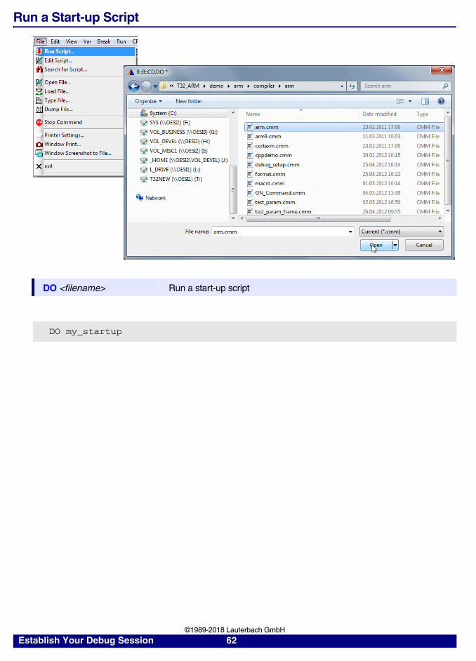
Run a Start-up Script
DO <filename> Run a start-up script
DO my_startup
Establish Your Debug Session 62 ©1989-2018 Lauterbach GmbH

Automated Start-up Scripts
There a two ways to define a start-up script, that is automatically started, when the debugger is started.
1. Define start-up script in conjunction with the executable
The debugger-executable can be started with the start-up script as parameters.
2. Use T32Start to define an automated start-up script
If you use T32Start to start the debugger, an automated start-up script can be defined.
c:\t32\t32arm.exe -s g:\and\arm\start.cmm
Establish Your Debug Session 63 ©1989-2018 Lauterbach GmbH