Embed Size (px)
Citation preview

1
ES330 Laboratory Experiment No. 8 Bipolar Phase Shift Oscillator
[Reference: Section 18.2.2 The Phase Shift oscillator – pp. 1391-2]
Objective: 1. To assemble and evaluate a discrete bipolar phase shift oscillator.
Materials: 1. Breadboard 2. NPN bipolar transistors – 2N3904 silicon transistors (see attached Data Sheet) 3. Several resistors as required for setting the transistor’s bias point and the feedback
RC network 5. Jumper wires for interconnection on your breadboard 6. Multimeter (or volt meters and current meter) for measuring voltages
7. Power supply and oscilloscope for observing the output oscillation signal
Circuit Schematic:

2
Circuit Components: The component parameters of the circuit are listed in the table below.
Component Value
Load resistor RC 2,200
Base resistor RBB1 39,000
Base resistor RBB2 12,000
Emitter resistor RE1 470
Feedback network resistors R
5,600
Feedback network resistor R1
3,300
Bypass capacitor CE 47 F
Output coupling capacitor COut
47 F
NPN transistor 2N3904 (or an equivalent substitute if provided)
3 Feedback network capacitors C
0.01 F (i.e., 10 nF or 10,000 pF)
V+ (or VCC) + 6 volts (nominal)
Parameter values for the 2N3904 bipolar transistor are provided in the 2N3904 Data
Sheet in the appendix at the end of this document.
Theory of the Phase Shift Oscillator
An oscillator produces a periodic output signal with no required input signal. Only a DC power source is required for operation. The function generator you have been using in these laboratory experiments is an oscillator, but with the added capability of shaping the output waveform. There are essentially two categories of oscillators: (a) relaxation oscillators and (b) feedback phase shift oscillators. In this laboratory we only consider the second category, namely, the feedback phase shift oscillator.
Consider the figure showing a feedback connection around a voltage gain block of gain
A. The feedback network is connected from the amplifier’s output back to the input. The voltage gain block labeled A is a bipolar common-emitter amplifier that you have already encountered in EE330. This gain block is inverting – it has voltage gain A with an output voltage Vout which is phase shifted by 180 degrees from the input because of the inverting

3
nature of a common-emitter stage. Suppose we directly connect the output signal Vout to the
input of the amplifier, with the feedback network absent; then Vout becomes the input signal Vin to the amplifier. Signal Vout is out of phase (assuming sinusoidal signals) with any applied input signal (Vin). In a connection where the feedback signal (Vout) subtracts from input signal (Vin), we have negative feedback and negative feedback can’t produce oscillations.
But positive feedback can generate oscillations. To set this up suppose the feedback
network adds an additional 180 degrees phase shift to the 180 degrees phase shift of the amplifier A – that means the so the signal through the feedback network is now in-phase with the input signal. For sinusoidal signals this is positive feedback and will result in oscillations
given enough loop voltage gain (network A has voltage gain but network has voltage loss). Returning to the schematic diagram of the phase shift oscillator circuit, the voltage gain
block is a standard common-emitter BJT amplifier and the feedback network shown with a shaded background is a three-section RC network. The feedback network is lossy so the voltage gain of the amplifier must provide sufficient voltage gain to overcome the loss from the
feedback network. The oscillation condition is (1) the loop gain (A = 1) to be equal unity
and (2) the total loop phase shift = 360 degrees (or an integer multiple of 360 degrees).
Analysis To analyze the feedback network we use the small-signal equivalent circuit:
4
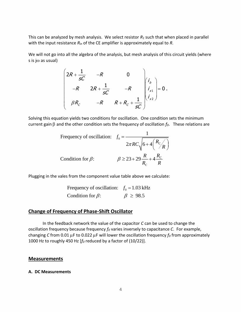
This can be analyzed by mesh analysis. We select resistor R1 such that when placed in parallel with the input resistance Rin of the CE amplifier is approximately equal to R. We will not go into all the algebra of the analysis, but mesh analysis of this circuit yields (where
s is j as usual) Solving this equation yields two conditions for oscillation. One condition sets the minimum
current gain and the other condition sets the frequency of oscillation f0. These relations are Plugging in the vales from the component value table above we calculate:
Change of Frequency of Phase-Shift Oscillator In the feedback network the value of the capacitor C can be used to change the oscillation frequency because frequency f0 varies inversely to capacitance C. For example,
changing C from 0.01 F to 0.022 F will lower the oscillation frequency f0 from approximately 1000 Hz to roughly 450 Hz [f0 reduced by a factor of (10/22)].
Measurements A. DC Measurements
1
2
12 0
12 0 .
1
b
x
x
C C
R RsC i
R R R isC
iR R R R
sC
0
1Frequency of oscillation:
2 6 4
Condition for : 23 29 4
C
C
C
fR
RCR
RR
R R
0Frequency of oscillation: 1.03 kHz
Condition for : 98.5
f

5
Assemble the circuit shown on page 1 of this Lab Experiment. First, check out the operation of the common-emitter amplifier – do not connect the RC feedback network yet to the amplifier because it will oscillate when connected (assuming it meets both oscillation conditions).
Upon assembly on the breadboard, you should first check out the bias points of the amplifier. Use a multimeter to measure voltages at the following nodes: (1) base node, (2) collector node and (3) emitter node. What do you measure for the base-emitter voltage VBE
and the collector-emitter voltage VCE? VBE = _______ volts
VCE = _______ volts Do these voltages bias the transistor within its forward active operating region? _________ You should have adequate collector-emitter voltage to swing at least 2 volts of signal. Next, you should test the gain of the amplifier. To make this measurement drive the base node with a function generator (sinusoidal output) that is AC coupled to the base node through a 47
F coupling capacitor and measure the collector voltage Vout. Use a test frequency of 1 kHz to perform this measurement. What voltage gain AV do you measure? AV = ______ (V/V) Once you have the voltage gain properly functioning, now connect the RC feedback
network . Do you obtain oscillations? And at what frequency f0 if you have oscillations? Oscillator frequency f0 = ________ kHz What kind of waveform do you observe on the oscilloscope? Take an image of the waveform or simply sketch its shape on the graph below.

6
B. Transient Measurements
Next, turn off the positive voltage supply V+ and then suddenly turn it back on with the
oscilloscope still displaying the output of the oscillator. The oscilloscope should catch the oscillator’s turn-on transient behavior.
Describe what you observe. You may want to capture an image of the oscilloscope
display of the transient turn-on or sketch on the graph below.
C. Change the frequency by a capacitor change in the feedback network
Finally, pick another capacitor value for capacitor C in the feedback network. Plug your
new capacitor value into the equations to predict the new frequency f’. Then build the
modified phase shift oscillator on your breadboard and record what frequency you actually measured.
f’ = __________ Hz
Conclusions:
(1) What have you learned from this laboratory experiment? Summarize your primary
findings below. (2) Describe any problems you may have encountered and tell how you solved the problem
encountered. Use a separate sheet of paper if necessary.

7
APPENDIX – 2N3904 DATA SHEET

8


![ES330 Laboratory Experiment No. 1 NPN Common-Emitter …ES330 Laboratory Experiment No. 1 NPN Common-Emitter Amplifier [Reference: Section 7.5.2 of Sedra & Smith (pp. 470-471)]](https://img.dokumen.tips/doc/110x75/5e4e56cb0406fa15a46f4ff6/es330-laboratory-experiment-no-1-npn-common-emitter-es330-laboratory-experiment.jpg)