Embed Size (px)
Citation preview

TuthillRotary Positive Displacement Blower
EqualizerOPERATOR’S MANUAL
Manual 2014 Rev D p/n 2014WARNING: Do Not Operate Before Reading Manual
Models DF - 4504 4506 4509 4512RM - 4604 4606 4609 4612
6012 6016 6024
Ope
rato
r’s M
anua
l: T
uthi
ll Eq
ualiz
er R
otar
y Po
sitiv
e D
ispl
acm
ent B
low
er
Copyright © 2019 Tuthill Springfield All rights reserved. Product information and specifications subject to change.
Tuthill Springfield | tuthillvacuumblower.com | 800.825.6937

Disclaimer Statement:All information, illustrations and specifications in this manual are based on the latest infor-mation available at the time of publishing. The illustrations used in this manual are intended as representative reference views only. Products are under a continuous improvement policy. Thus, information, illustrations and/or specifications to explain and or exemplify a product, service or maintenance improvement may be changed at any time without notice.
Rights Reserved Statement:No part of this publication may be reproduced or used in any form by any means - graphic, electronic or mechanical, including photocopying, recording, taping or information storage and retrieval systems - without the written permission of Tuthill Springfield.
Copyright © 2019 Tuthill SpringfieldAll rights reserved. Product information and specifications subject to change.
The employees of Tuthill Springfield thank you for your purchase!
Tuthill Springfield proudly manufactures Kinney® vacuum pumps and M-D PneumaticsTM blowers and vacuum boost-ers in Springfield, Missouri, USA. We bring 100+ years of engineering experience and solid, hands-on care to help customers keep their processes running. Your satisfaction is important to us so please take time to provide your Tut-hill sales representative with performance feedback. We love to hear from our customers!
Tuthill is a family owned business that was started by James B. Tuthill in 1892. At that time, Tuthill manufac-tured common brick to Chicago construction companies who were fueling the city’s rapid expansion. Fast forward to today and Tuthill now serves sustaining, global markets like agriculture, chemical, construction, energy, food and beverage, pharmaceuticals and medical, transportation, and utilities. While the company has changed in what it manufactures, one thing remains throughout every Tuthill line of business – we are a company with HEART. Our slogan is “Pump Your Heart Into It” and everyday our employees do just that as they represent the Tuthill brand and dare to make better.
Thank you for making Tuthill Springfield part of your com-pany’s process! FIND OUT MORE AT
TUTHILL.COM
A company with heart right from the start.
iManual 2014 Rev D p/n 2014
Table of ContentsIntroduction .................................................................................. 1
Applicable Documentation ................................................................... 1
Scope of Manual ................................................................................... 1
Conventions and Data Plate ....................................................... 2Graphic Conventions Used in this Manual ............................................ 2
Data Plate .............................................................................................. 3
Lifting ............................................................................................ 5Description ................................................................................... 6
Flow By Direction .................................................................................. 7
Specifications ........................................................................................ 8
Flow Configurations ............................................................................ 10
Special Note Regarding 4600 and 6000 Equalizer RM Models ......... 10
Installation ...................................................................................11General ............................................................................................... 11
Location .............................................................................................. 13
Foundation .......................................................................................... 13
Blower Air Intake ................................................................................. 13
Soft Foot .............................................................................................. 14
Safety .................................................................................................. 14
Lubrication .......................................................................................... 15
Filling Procedure ...................................................................... 16
Frequently Asked Questions Regarding Lubrication .......................... 17
ii
Table of Contents
Manual 2014 Rev D p/n 2014
Hazards Associated With Breakdown or Ignition of Lubrication ............................................................................... 17
Piping Connections ............................................................................. 17
Hazards Associated With Hazardous Process Fluids .............. 18
Blockage or Restriction ............................................................ 18
Motor Drives ........................................................................................ 18
Direct Coupled ......................................................................... 19
V-Belts ...................................................................................... 19
Setting V-Belt Tension ............................................................... 19
V-Belt Troubleshooting ............................................................. 21
Motor and Electrical Connections ....................................................... 22
Operation .................................................................................... 23General ............................................................................................... 23
Start-Up Checklist ............................................................................... 24
Operating ............................................................................................ 25
Stopping .............................................................................................. 25
Recommended Shutdown Procedure to Minimize Risk of Freezing or Corrosion ......................................................................... 26
Maintenance ............................................................................... 27General ............................................................................................... 27
Regular Maintenance .......................................................................... 28
Spare Parts ......................................................................................... 28
Factory Service and Repair ................................................................ 29
Long-Term Storage ............................................................................. 29
Disassembly and Reassembly .................................................. 30Disassembly & Inspection .................................................................. 30
Disassembly of Blower ....................................................................... 31
Assembly of Blower ............................................................................ 31
Preparation of End Plates and Rotors for Assembly ................ 32
Gear End Assembly ................................................................. 32
iii
Table of Contents
Manual 2014 Rev D p/n 2014
Drive End Assembly ................................................................. 34
Adjusting Rotor Interlobe Clearance ........................................ 34
Troubleshooting ......................................................................... 36Assembly Clearances ................................................................ 38Maintenance ............................................................................... 39Recommended Lubricants ........................................................ 40
Recommended Lubricants for Rotary Blowers and Vacuum Boosters .............................................................................................. 40
Special Tool Drawings ............................................................... 42Parts List ............................................................................................. 44
Parts List for Equalizer DF Model 4500 Series Blowers ........... 44
Parts List for Equalizer RM Model 4600 Series Blowers .......... 45
Parts List for Equalizer RM Model 6000 Series Blowers .......... 46
Assembly Drawings ............................................................................ 47
Cutaway Drawings for Models 4504, 4506, 4509, and 4512 ... 47
Cutaway Drawings for Models 4604, 4606, 4609, and 4612 ... 48
Cutaway Drawings for Models 6012, 6016, and 6024 ............. 49
Warranty – Blower Products ..................................................... 50Operating Data Form / Product Registration ........................... 51

iv
Table of Contents
Manual 2014 Rev D p/n 2014
1Manual 2014 Rev D p/n 2014
CONGRATULATIONS on the purchase of a new Equalizer® Rotary Positive Displacement Blower from Tuthill Springfield. Please examine the blower for shipping damage, and if any damage is found, report it immediately to the carrier. If the blower is to be installed at a later date, make sure it is stored in a clean, dry location and rotated regularly. Make sure covers are kept on all openings. If the blower is stored outdoors, be sure to protect it from weather and corrosion.
Equalizer blowers are built to exacting standards and, if properly installed and maintained, will provide many years of reliable service. Read and follow every step of these instructions when installing and maintaining the blower.
OTE: N Record the blower model and serial numbers of the machine in the OPERATING DATA form on the inside back cover of this manual. Use this identification on any replacement part orders, or if service or application assistance is required.
APPLICABLE DOCUMENTATION
The applicable documents associated with this manual are:
• 2006/42/CE – Machinery Directive• EN 1012-1:1996 - Compressors and vacuum
pumps - Safety Requirements - Part 1: Compressors
SCOPE OF MANUAL
The scope of this manual and the Declaration of Incorporation includes the bare shaft rotary positive displacement blower.
INTRODUCTION
01

2 Manual 2014 Rev C p/n 2014
GRAPHIC CONVENTIONS USED IN THIS MANUAL
This manual is the result of a risk assessment according to the applicable documents referenced in Applicable Documentation on page 1.
The following hazard levels are referenced within this manual:
DANGER!Indicates a hazardous situation that, if not avoided, will result in death or serious injury.
WARNING!Indicates a hazardous situation that, if not avoided, could result in death or serious injury.
CAUTION!Indicates a hazardous situation that, if not avoided, could result in minor or moderate injury.
Indicates a situation that can cause damage to the engine, personal property, and/or the environment or cause the equipment to operate improperly.
OTE: N Indicates a procedure, practice, or condition that should be followed in order for the equipment to function in the manner intended.
CAUTION!Read manual before operation or bodily harm may result. Attention should be given to the safety related sections of this manual.
CONVENTIONS AND DATA PLATE
02

3
02Conventions and Data Plate
Manual 2014 Rev D p/n 2014
DATA PLATE
WARNING WARNING CAUTION CAUTION
http://www.tuthill.com
Hearing protection required.
Do not touch hot surfaces.
ASU eht ni edaM7396-528 )008(
READ INSTRUCTION MANUAL BEFORE OPERATION OR BODILY HARM MAY RESULT
Keep body & clothing away from machine openings.
Do not operate without guards in place.
REBMUN LAIRESREBMUN LEDOM
Tuthill Vacuum & Blower Systems4840 West Kearney Street
Springfield, Missouri USA 65803
YEARMAWP
MAX RPM
Figure 2-1 – General Operation and Symbols on Data Plate
The following information is contained on the data plate:
WARNING!Keep body and clothing away from machine.
During operation, keep body and clothing away from inlet and outlet of the booster.
WARNING!Do not operate without guards in place.
CAUTION!Hearing protection is required while the booster is in operation. Noise levels may reach as high as 81 dBA.
CAUTION!Do not touch hot surfaces.
The upper limit of the booster operation is 445°F (229°C). Do not touch the booster while it is in operation and assure booster is cool when not in operation.

4
02 Conventions and Data Plate
Manual 2014 Rev D p/n 2014
MODEL NUMBER: The specific model of the blower
SERIAL NUMBER: Unique to each blower
YEAR: Year of manufacture
MAWP: Maximum Allowable Working Pressure
The standard MAWP is per Table 4-2 on page 9. The MAWP shall not be exceeded.

5Manual 2014 Rev D p/n 2014
WARNING!The blower must be handled using an appropriate device such as a fork truck or other appropriate lifting device. See Table 4-1 on page 8 for approximate weights. Care should be taken to assure blower does not over-turn during handling and installation.
03LIFTING

6 Manual 2014 Rev D p/n 2014
Refer to specific data sheets for flow capacities and vacuum capacities.
OTE: N Refer to diagrams in this manual for proper rotation and orientation in inlet and discharge.
Tuthill Springfield Equalizer DF and Equalizer RM rotary lobe blowers are positive displacement type blowers, whose pumping capacity is determined by size, operating speed, and differential pressure conditions. Blowers employ rotors rotating in opposite directions within a housing closed at the ends by end plates.
The inlet to the discharge is sealed with operating clearances that are very small. Internal lubrication is not needed, as there is no moving contact.
Clearances between the rotors during rotation are maintained by a pair of accurately machined helical timing gears, mounted on the two shafts extended outside the air chamber. The intermeshing rotary lobes are designed to rotate and trap air or gas between each rotor and the housing. As the rotor lobes rotate past the edge of the suction port, the trapped air or gas is essentially at suction pressure and temperature. Since the blower is a constant volume device, the trapped air remains at suction pressure until the leading rotor lobe opens into the discharge port. The close clearances between the rotors inhibit back slippage of the trapped volume from between the rotors, and the trapped volume is forced into the discharge piping. Compression occurs not internal to the blower but by the amount of restriction, either downstream of the blower
discharge port or upstream of the blower inlet port.
Figure 4-1 illustrates the air movement within the machine. In addition, the machine can operate in either direction.
Protect the blowers with cut-in switches or with bypass valving to limit differential pressure across the blower. See Table 4-2 on page 9 for more information. When a belt drive is used, it is possible to adjust blower speed to obtain the desired capacity by changing the diameter of one or both sheaves, or by using a variable-speed motor pulley.
DESCRIPTION
04

7
04Description
Manual 2014 Rev D p/n 2014
INLET INLET INLET
DISCHARGE DISCHARGE DISCHARGE
Figure 4-1 – General Operation Principle
FLOW BY DIRECTION
WARNING!Refer to diagrams in this manual for proper rotation and orientation in inlet and discharge.
INTAKEINTAKE
DISCHARGE INTAKE
DISCHARGE
HORIZONTAL FLOWVERTICAL FLOW
DISCHARGE
INTAKE DISCHARGE
INTAKE
DISCHARGERIGHT DRIVE
CW ROTATIONLEFT DRIVE
CW ROTATIONLEFT DRIVE
CCW ROTATIONRIGHT DRIVE
CCW ROTATION
TOP DRIVECW ROTATION
TOP DRIVECCW ROTATION
BOTTOM DRIVECW ROTATION
BOTTOM DRIVECCW ROTATION
DISCHARGEINTAKE INTAKE
INTAKEDISCHARGE DISCHARGE
Figure 4-2 – Flow Direction by Rotation

8
04 Description
Manual 2014 Rev D p/n 2014
SPECIFICATIONS
MODEL
APPROXIMATE OIL CAPACITY
PORT SIZE MAXIMUM RPM
APPROXIMATE WEIGHT
VERTICAL FLOW HORIZONTAL FLOWGEAR END
DRIVE END
GEAR END
DRIVE END
4504 32.0 oz (0.95 mL)
23.0 oz (0.68 mL)
16 oz (0.47 mL)
13.0 oz (0.38 mL)
SOLD SEPERATELY
4,000 270 lb (122 kg)
4506 32.0 oz (0.95 mL)
23.0 oz (0.68 mL)
16 oz (0.47 mL)
13.0 oz (0.38 mL) 4,000 310 lb (141 kg)
4509 32.0 oz (0.95 mL)
23.0 oz (0.68 mL)
16 oz (0.47 mL)
13.0 oz (0.38 mL) 4,000 350 lb (159 kg)
4512 32.0 oz (0.95 mL)
23.0 oz (0.68 mL)
16 oz (0.47 mL)
13.0 oz (0.38 mL) 4,000 390 lb (177 kg)
4604 32.0 oz (0.95 mL)
17.0 oz (0.50 mL)
16 oz (0.47 mL)
11.0 oz (0.33 mL) 4 in. (102 mm) 4,000 210 lb (95 kg)
4606 32.0 oz (0.95 mL)
17.0 oz (0.50 mL)
16 oz (0.47 mL)
11.0 oz (0.33 mL) 4 in. (102 mm) 4,000 245 lb (111 kg)
4609 32.0 oz (0.95 mL)
17.0 oz (0.50 mL)
16 oz (0.47 mL)
11.0 oz (0.33 mL) 4 in. (102 mm) 4,000 280 lb (127 kg)
4612 32.0 oz (0.95 mL)
17.0 oz (0.50 mL)
16 oz (0.47 mL)
11.0 oz (0.33 mL) 6 in. (152 mm) 4,000 320 lb (145 kg)
6012 57.0 oz (1.69 mL)
41.0 oz (1.21 mL)
34 oz (1.01 mL)
22.0 oz (0.65 mL) 8 in. (203 mm) 3,000 590 lb (268 kg)
6016 57.0 oz (1.69 mL)
41.0 oz (1.21 mL)
34 oz (1.01 mL)
22.0 oz (0.65 mL) 8 in. (203 mm) 3,000 650 lb (295 kg)
6024 57.0 oz (1.69 mL)
41.0 oz (1.21 mL)
34 oz (1.01 mL)
22.0 oz (0.65 mL) 10 in. (254 mm) 3,000 775 lb (352 kg)
Table 4-1 – Specifications
9
04Description
Manual 2014 Rev D p/n 2014
MODEL MAXIMUM RPM
MAXIMUM PRESSURE
DIFFERENTIAL
MAXIMUM VACUUM
MAXIMUM TEMPERATURE
RISEMAWP
4504 4,000 18 psi (1,241 mbar) 16 inch-Hg (542 mbar) 290°F (161°C) 20 psi
(1,379 bar)
4506 4,000 18 psi (1,241 mbar) 16 inch-Hg (542 mbar) 265°F (147°C) 20 psi
(1,379 bar)
4509 4,000 18 psi (1,241 mbar) 16 inch-Hg (542 mbar) 260°F (144°C) 20 psi
(1,379 bar)
4512 4,000 15 psi (1,034 mbar) 16 inch-Hg (542 mbar) 255°F (142°C) 20 psi
(1,379 bar)
4604 4,000 18 psi (1,241 mbar) 16 inch-Hg (542 mbar) 290°F (161°C) 20 psi
(1,379 bar)
4606 4,000 18 psi (1,241 mbar) 16 inch-Hg (542 mbar) 265°F (147°C) 20 psi
(1,379 bar)
4609 4,000 18 psi (1,241 mbar) 16 inch-Hg (542 mbar) 260°F (144°C) 20 psi
(1,379 bar)
4612 4,000 15 psi (1,034 mbar) 16 inch-Hg (542 mbar) 255°F (142°C) 20 psi
(1,379 bar)
6012 3,000 15 psi (1,034 mbar) 16 inch-Hg (542 mbar) 280°F (156°C) 20 psi
(1,379 bar)
6016 3,000 15 psi (1,034 mbar) 16 inch-Hg (542 mbar) 280°F (156°C) 20 psi
(1,379 bar)
6024 3,000 10 psi (690 mbar) 16 inch-Hg (542 mbar) 230°F (128°C) 20 psi
(1,379 bar)
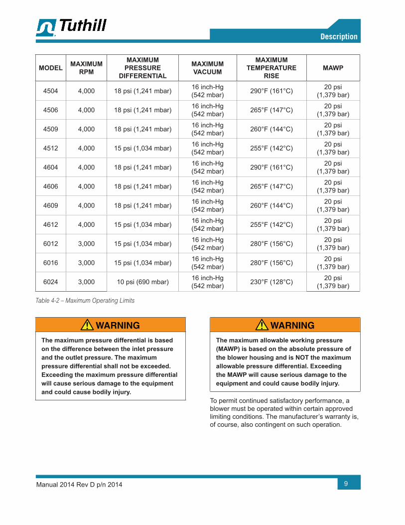
Table 4-2 – Maximum Operating Limits
WARNING!The maximum pressure differential is based on the difference between the inlet pressure and the outlet pressure. The maximum pressure differential shall not be exceeded. Exceeding the maximum pressure differential will cause serious damage to the equipment and could cause bodily injury.
WARNING!The maximum allowable working pressure (MAWP) is based on the absolute pressure of the blower housing and is NOT the maximum allowable pressure differential. Exceeding the MAWP will cause serious damage to the equipment and could cause bodily injury.
To permit continued satisfactory performance, a blower must be operated within certain approved limiting conditions. The manufacturer’s warranty is, of course, also contingent on such operation.

10
04 Description
Manual 2014 Rev D p/n 2014
Maximum limits for pressure, temperature, and speed are specified in Table 4-2 on Page 9 for various blower sizes when operated under the standard atmospheric conditions. Do not exceed any of these limits.
Specially ordered blowers with nonstandard construction, or with rotor end clearances greater than shown within the Assembly Clearances table, will not have the operating limits specified here. Contact your Tuthill Springfield sales representative for specific information.
Special attention must be paid when a blower has a higher than standard ambient suction temperature. Special recommendations for operating parameters and/or additional cooling may be recommended. Consult the factory or local representative for appropriate information.
FLOW CONFIGURATIONS
• The EQUALIZER blowers can be shipped from the factory in a horizontal flow configuration.With horizontal flow, a bottom drive configuration is now available on 4500 EQUALIZER DF and 6000 Equalizer RM models.
• The EQUALIZER blowers can also be shipped from the factory in either left drive or right drive with vertical flow configuration.
• If the flow direction is changed, relocate the oil level sight glasses and breathers to the proper positions, as shown in Figure 4-3.
Failure to change plug location will result in blower failure and void the product warranty.
SPECIAL NOTE REGARDING 4600 AND 6000 EQUALIZER RM MODELS
• Vertical flow 4600 and 6000 EQUALIZER RM blowers with either left or right drive can be converted to top drive. However, a left drive blower cannot be converted to right drive, and vice versa.
• Top drive 4600 and 6000 EQUALIZER RM blowers can be converted to left drive only. Either left or right drive blowers can be converted to top drive.
Unless specifically stated by the factory, never arrange the blower so that the flow direction is horizontal with bottom drive. This will result in blower failure and void the product warranty.
• Bottom drive can be converted to right drive only.
• Top drive can be converted to left drive only.
HORIZONTAL FLOWVERTICAL FLOW
BREATHERS(OIL FILL)
BREATHERS(OIL FILL)
SIGHTGLASSES SIGHT
GLASSES
DRAINPLUG DRAIN
PLUG
4500, 4600 & 6000 SERIES UNITS CAN BE ORDERED WITH
BOTTOM DRIVE
Figure 4-3 – Flow Configurations
11Manual 2014 Rev D p/n 2014
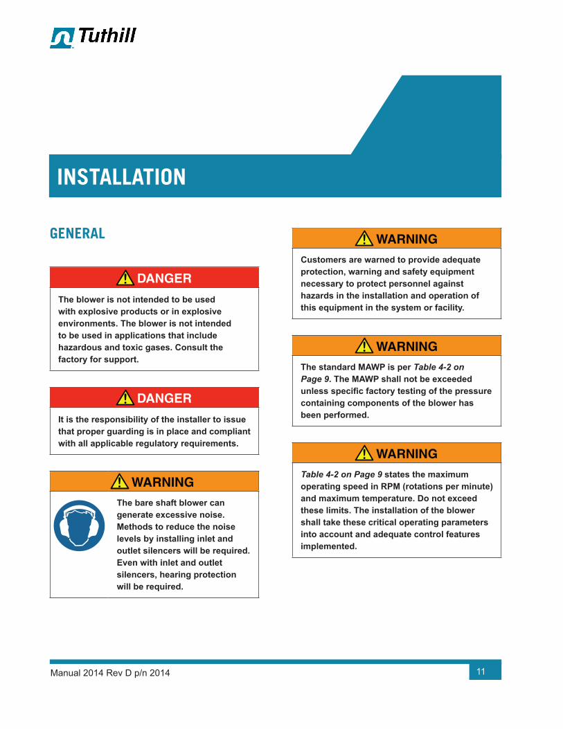
GENERAL
DANGER!The blower is not intended to be used with explosive products or in explosive environments. The blower is not intended to be used in applications that include hazardous and toxic gases. Consult the factory for support.
DANGER!It is the responsibility of the installer to issue that proper guarding is in place and compliant with all applicable regulatory requirements.
WARNING!The bare shaft blower can generate excessive noise. Methods to reduce the noise levels by installing inlet and outlet silencers will be required. Even with inlet and outlet silencers, hearing protection will be required.
WARNING!Customers are warned to provide adequate protection, warning and safety equipment necessary to protect personnel against hazards in the installation and operation of this equipment in the system or facility.
WARNING!The standard MAWP is per Table 4-2 on Page 9. The MAWP shall not be exceeded unless specific factory testing of the pressure containing components of the blower has been performed.
WARNING!Table 4-2 on Page 9 states the maximum operating speed in RPM (rotations per minute)and maximum temperature. Do not exceed these limits. The installation of the blower shall take these critical operating parameters into account and adequate control features implemented.
INSTALLATION
05
12
05Installation
Manual 2014 Rev D p/n 2014
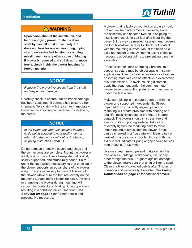
WARNING!Upon completion of the installation, and before applying power, rotate the drive shaft by hand. It must move freely. If it does not, look for uneven mounting, piping strain, excessive belt tension or coupling misalignment or any other cause of binding. If blower is removed and still does not move freely, check inside the blower housing for foreign material.
Remove the protective covers from the shaft and inspect for damage.
Carefully check to ensure that no transit damage has been sustained. If damage has occurred from shipment, file a claim with the carrier immediately. Preserve the shipping container for inspection by the carrier.
In the event that your unit sustains damage while being shipped to your facility, do not return it to the factory without first obtaining shipping instructions from us.
Do not remove protective covers and plugs until the connections are complete. Mount the blower on a flat, level surface. Use a baseplate that is rigid, solidly supported, and structurally sound. Shim under the legs where necessary so that each leg of the blower supports an equal share of the blower weight. This is necessary to prevent twisting of the blower. Make sure the feet rest evenly on the mounting surface before fastening down. Twisting or cramping the blower during mounting will cause rotor contact and binding during operation, resulting in a condition called “soft foot.” See Soft Foot on page 14 for further details and preventative measures.
A blower that is factory-mounted on a base should not require such adjustments. However, since the assembly can become twisted in shipping or installation, check for soft foot after installing the base. Shims may be needed for alignment. Loosen the foot hold-down screws to check foot contact with the mounting surface. Mount the base on a solid foundation or heavy flooring, using shims as necessary at bolting points to prevent warping the assembly.
Transmission of small operating vibrations to a support structure may be objectionable in some applications. Use of vibration isolators or vibration-absorbing materials can be effective in overcoming this transmission. To avoid causing distortion, apply the treatment under the common motor/blower base or mounting plate rather than directly under the feet alone.
Make sure piping is accurately squared with the blower and supported independently. Stress imparted from incorrectly aligned piping or mounting will create problems with bearing and seal life, possibly leading to premature internal contact. The blower should sit stress free and evenly on its supporting surface. Take care to evenly tighten the mounting bolts to avoid imparting undue stress into the blower. Stress can be checked in a free state with feeler stock or verified on a previously installed blower with the aid of a dial indicator. Spring or gap should be less than 0.002 in. (0.05 mm).
Use only clean, new pipe and make certain it is free of scale, cuttings, weld beads, dirt, or any other foreign material. To guard against damage to the blower, make sure that an inlet filter is used. Clean the filter of collected debris after 3 hours of operation and periodically thereafter. See Piping Connections on page 17 for additional details.
13
05Installation
Manual 2014 Rev D p/n 2014
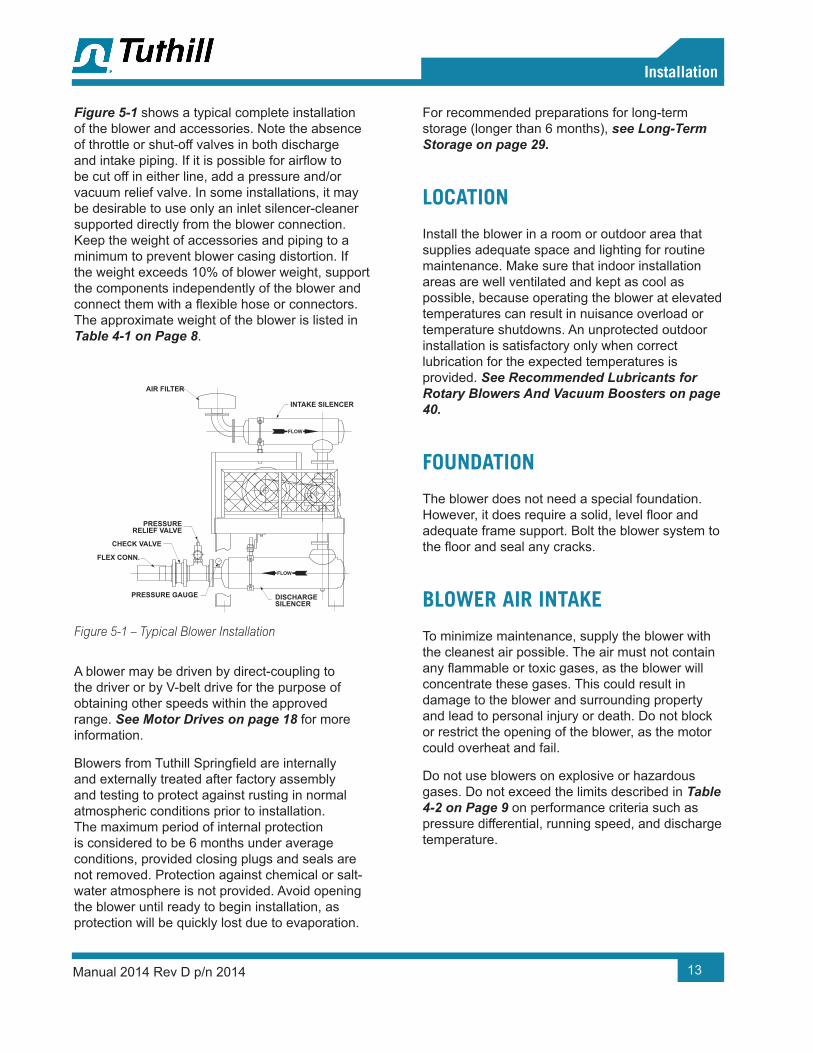
Figure 5-1 shows a typical complete installation of the blower and accessories. Note the absence of throttle or shut-off valves in both discharge and intake piping. If it is possible for airflow to be cut off in either line, add a pressure and/or vacuum relief valve. In some installations, it may be desirable to use only an inlet silencer-cleaner supported directly from the blower connection. Keep the weight of accessories and piping to a minimum to prevent blower casing distortion. If the weight exceeds 10% of blower weight, support the components independently of the blower and connect them with a flexible hose or connectors. The approximate weight of the blower is listed in Table 4-1 on Page 8.
AIR FILTER
PRESSURERELIEF VALVE
CHECK VALVE
FLEX CONN.
PRESSURE GAUGE DISCHARGESILENCER
INTAKE SILENCER
FLOW
FLOW
Figure 5-1 – Typical Blower Installation
A blower may be driven by direct-coupling to the driver or by V-belt drive for the purpose of obtaining other speeds within the approved range. See Motor Drives on page 18 for more information.
Blowers from Tuthill Springfield are internally and externally treated after factory assembly and testing to protect against rusting in normal atmospheric conditions prior to installation. The maximum period of internal protection is considered to be 6 months under average conditions, provided closing plugs and seals are not removed. Protection against chemical or salt-water atmosphere is not provided. Avoid opening the blower until ready to begin installation, as protection will be quickly lost due to evaporation.
For recommended preparations for long-term storage (longer than 6 months), see Long-Term Storage on page 29.
LOCATION
Install the blower in a room or outdoor area that supplies adequate space and lighting for routine maintenance. Make sure that indoor installation areas are well ventilated and kept as cool as possible, because operating the blower at elevated temperatures can result in nuisance overload or temperature shutdowns. An unprotected outdoor installation is satisfactory only when correct lubrication for the expected temperatures is provided. See Recommended Lubricants for Rotary Blowers And Vacuum Boosters on page 40.
FOUNDATION
The blower does not need a special foundation. However, it does require a solid, level floor and adequate frame support. Bolt the blower system to the floor and seal any cracks.
BLOWER AIR INTAKE
To minimize maintenance, supply the blower with the cleanest air possible. The air must not contain any flammable or toxic gases, as the blower will concentrate these gases. This could result in damage to the blower and surrounding property and lead to personal injury or death. Do not block or restrict the opening of the blower, as the motor could overheat and fail.
Do not use blowers on explosive or hazardous gases. Do not exceed the limits described in Table 4-2 on Page 9 on performance criteria such as pressure differential, running speed, and discharge temperature.
14
05Installation
Manual 2014 Rev D p/n 2014
If it is necessary to take air from a remote source, such as in a vacuum application, make sure the diameter of the piping is at least equal to the diameter of the blower inlet. For distances greater than 20 ft (6 m), enlarge the pipe diameter to reduce inlet restriction. Excessive restriction will reduce the efficiency of the blower and elevate its discharge temperature. The piping used should also be corrosion-resistant and free of scale and dirt. Keep the inlet covered to keep out foreign objects and rain. Vacuum kits are available.
SOFT FOOT
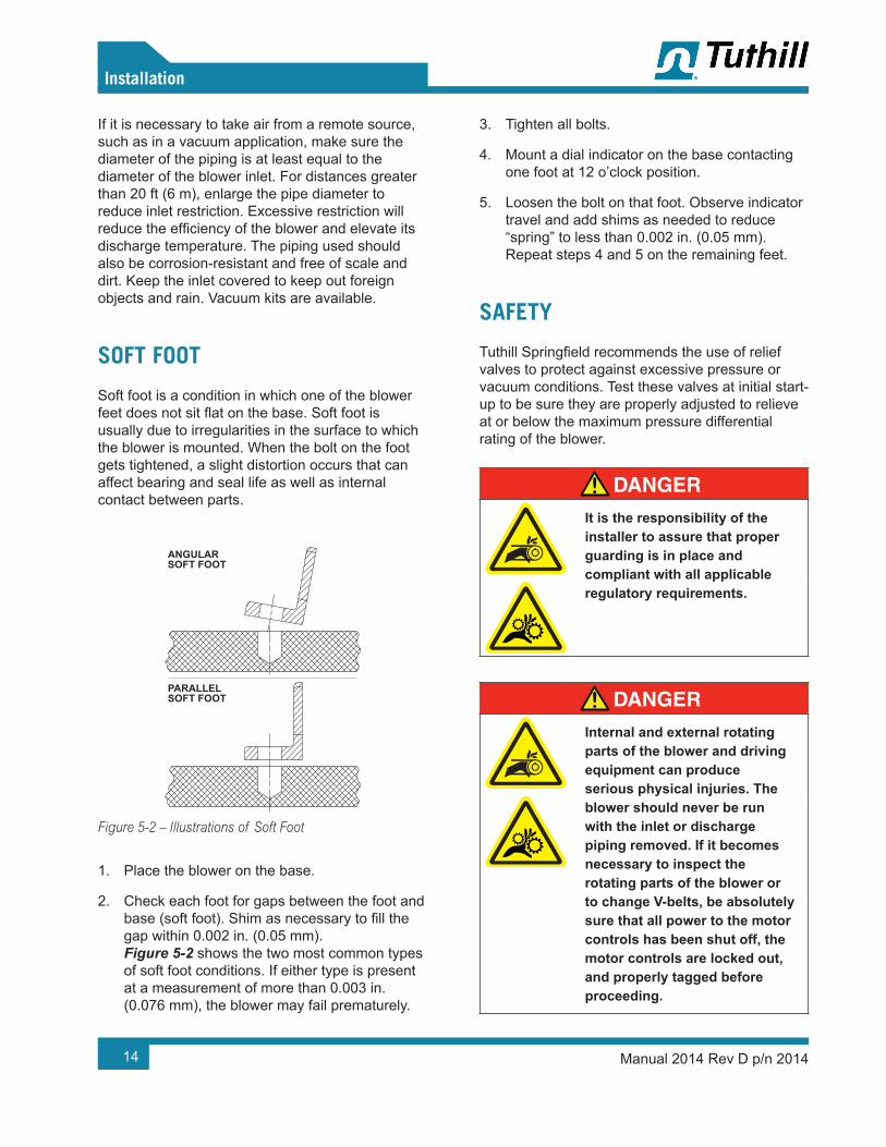
Soft foot is a condition in which one of the blower feet does not sit flat on the base. Soft foot is usually due to irregularities in the surface to which the blower is mounted. When the bolt on the foot gets tightened, a slight distortion occurs that can affect bearing and seal life as well as internal contact between parts.
ANGULARSOFT FOOT
PARALLELSOFT FOOT
Figure 5-2 – Illustrations of Soft Foot
1. Place the blower on the base.
2. Check each foot for gaps between the foot and base (soft foot). Shim as necessary to fill the gap within 0.002 in. (0.05 mm). Figure 5-2 shows the two most common types of soft foot conditions. If either type is present at a measurement of more than 0.003 in. (0.076 mm), the blower may fail prematurely.
3. Tighten all bolts.
4. Mount a dial indicator on the base contacting one foot at 12 o’clock position.
5. Loosen the bolt on that foot. Observe indicator travel and add shims as needed to reduce “spring” to less than 0.002 in. (0.05 mm). Repeat steps 4 and 5 on the remaining feet.
SAFETY
Tuthill Springfield recommends the use of relief valves to protect against excessive pressure or vacuum conditions. Test these valves at initial start-up to be sure they are properly adjusted to relieve at or below the maximum pressure differential rating of the blower.
DANGER!It is the responsibility of the installer to assure that proper guarding is in place and compliant with all applicable regulatory requirements.
DANGER!Internal and external rotating parts of the blower and driving equipment can produce serious physical injuries. The blower should never be run with the inlet or discharge piping removed. If it becomes necessary to inspect the rotating parts of the blower or to change V-belts, be absolutely sure that all power to the motor controls has been shut off, the motor controls are locked out, and properly tagged before proceeding.
15
05Installation
Manual 2014 Rev D p/n 2014
DANGER!Assure that properly sized vacuum breaks/relief valves are used on the inlet side of the blower. Also assure that properly sized pressure relief valves are used on the outlet of the blower. The sizing shall be such to assure that the proper flow can be achieved without exceeding the rated vacuum and pressure ratings.
DANGER!Blower housing and associated piping or accessories may become hot enough to cause major skin burns on contact.
WARNING!Use lock out/tag out procedures to disable the electrical energy source before any service or work is done on the blower.
WARNING!Avoid extended exposure in close proximity to machinery with high intensity noise levels. Wear adequate ear protection.
OTE: N Use proper care and good procedures in handling, lifting, installing, operating, and maintaining the equipment
LUBRICATION
Every blower from Tuthill Springfield is factory-tested, oil-drained, and shipped dry to its installation point. Fill both independent oil reservoirs to the proper level before operation. Oil reservoirs are under the vacuum.
Shaft bearings at the gear end of the blower are splash-lubricated by one or both gears dipping into an oil reservoir formed in the gear end plate and cover. Shaft bearings at the drive end of the blower are lubricated by a slinger assembly dipping into an oil reservoir. Before starting the blower, fill the oil sumps as described in Filling Procedure on page 16.
Add oil to the blower in the quantity listed in Table 4-1 on Page 8. Make sure oil level is maintained within the notched area of the sight glass. See Figure 5-3. Lower drive blowers have “bull’s eye” type oil level gauges. Maintain oil levels at the center of the glass.
WARNING!Never attempt to change or add lubrication while the blower is running. Failure to heed this warning could result in damage to the equipment or personal injury. Oil must be checked when the blower is NOT running.
WARNING!Properly dispose of the spent lubricants. Refer to the manufacturer of the lubricant and any regulations to assure proper and safe disposal.
WARNING!Do not start the blower until you are sure oil has been put in the gear housing and rear cover. Operation of the blower without proper lubrication will cause the blower to fail and void the warranty.

16
05Installation
Manual 2014 Rev D p/n 2014
Assure oil is compatible with copper/yellow metals (if equipped with cooling coils).
See Table 4-1 for oil capacities.
Filling Procedure
See Figure 5-3. See Recommended Lubricants on page 40 for suggested lubricants and grease.
1. Remove the fill plugs or breathers from both gear end and drive end plates.
2. Slowly pour oil through the fill until oil appears in the oil sight glass. Bring the oil level to the center of the sight glass.
3. Verify oil level is at proper level in both gear end and drive end sight glasses.
4. Replace the fill plugs or breathers that were removed in step 1.
Figure 5-3 – Oil Fill, Drain and Level Plugs, and Level Gauges

17
05Installation
Manual 2014 Rev D p/n 2014
FREQUENTLY ASKED QUESTIONS REGARDING LUBRICATION
What is the functional detriment if the “wrong oil” is used?
The lubricant is selected based on bearing speed, gear speed, and operating temperature. If the lubricant is too light, it increases wear by not separating the sliding surfaces and it will not remove the heat adequately. If the lubricant is too thick, the drag in the bearings is increased, causing them to run hotter. Thicker lubricant will not flow as readily into the gears and it will reduce the available backlash. Lubricants at our conditions are incompressible.
What is the functional detriment if the oil is not serviced?
If the lubricant is not serviced at the proper interval, the shearing action in the bearing and the gears will begin to take its toll and the lubricant will thicken. The blower will run hotter and the wear on moving parts will increase. The lubricant will generally appear dirtier, caused by material rubbing off the components. The lubricant will discolor because of overheating. An indicator of the breakdown of a lubricant is the increase in the Total Acid Number (TAN) and a change of 10 percent in the base viscosity.
Several things are happening as the lubricant goes through the blower. First, it is absorbing frictional energy in the form of heat. This heat has to be dissipated through either surface contact with cooler materials or in a rest volume of lubricant. While reducing the friction, the lubricant is also going through a shearing process and the molecular structure is broken down.
The result is that the lubricant will begin to thicken because of the shorter molecular chains and the drop out of additive packages. The thickened lubricant will cause more drag, increasing the friction and heat and further degrading the lubricant.
Operation of the blower (environment, run time, speed, and pressure) has a direct effect on duty cycles. The published cycles are based on worst-case conditions.
Hazards Associated With Breakdown or Ignition of Lubrication
DANGER!There is a risk associated with the lubrication media breaking down and resulting in a hazardous fluid or vapor. There may also be a hazard associated with the ignition of the lubrication media. Refer to the lubrication manufacturer’s applicable instruction for safety precautions.
PIPING CONNECTIONS
WARNING!Pipe loading on the blower should be negligible as pipe loading can cause distortion of the blower. Use proper supports and pipe hangers to assure that there is no loading.
CAUTION!If the blower is to be located outdoors or in a building where the temperature surrounding the blower or the water supply and return piping can fall below 35°F (2°C), then care must be taken to ensure that the water (or other cooling liquid) does not freeze and cause damage. Heat exchanger and cooling lines must be drained of liquid during downtime unless a recirculating unit using a glycol mixture has been installed.
18
05Installation
Manual 2014 Rev D p/n 2014
Units are never shipped from the manufacturer with liquid in the heat exchanger or cooling lines.
Remove the protective covers from the inlet and outlet ports and inspect for dirt and foreign material.
Inlet and outlet connections on all blowers are large enough to handle maximum volume with minimum friction loss. Maintain same-diameter piping. Do not support silencers by the blower. Avoid stress loads and bending moments.
Be certain all piping is clean internally before connecting to the blower. Place a 16-mesh wire screen backed with hardware cloth at or near the inlet connections for the first 50 hours of use until the system is clean. Clean the screen after 3 hours of operation and completely discard it once the system is clean, as it will eventually deteriorate and small pieces going into the blower can cause serious damage. A horizontal or vertical airflow piping configuration is easily achieved by rearranging the mounting feet position.
Hazards Associated With Hazardous Process Fluids
DANGER!It shall be the responsibility of the installer to ensure that piping is adequate, sealing between pipe joints is adequate for the process fluids and proper process and pressure protection devices are in place. It is also the responsibility of the installer to assure that process gasses are not vented in a manner that would be hazardous.
Refer to the manufacturer of the process media to assure that proper safety precautions are in place.
Blockage or Restriction
WARNING!Damage to the blower could occur if there is blockage in the inlet or outlet ports or piping. Care should be taken when installing the blower to assure that there are no foreign objects or restrictions in the ports or piping.
MOTOR DRIVES
Two drive connections commonly used are direct
drive and V-belt drive.

19
05Installation
Manual 2014 Rev D p/n 2014
Direct Coupled
When installing the motor directly to the blower, align the shafts to the coupling according to the coupling manufacturer’s instructions. Blowers shipped with the motor directly coupled and mounted on a common base have been aligned prior to shipment. Further alignment is not normally necessary, but be sure to check the alignment and make adjustments if necessary prior to starting the blower.
Coupling halves must correctly fit the blower and drive shafts so that only light tapping is required to install each half. The two shafts must be accurately aligned. A direct-coupled blower and motor must be aligned with the two shafts having no more than 0.005 in. (13 mm) Total Indicator Reading (TIR). Make sure the face is aligned within 0.002 in. (0.05 mm).
Establish proper gap between coupling halves according to the coupling manufacturer’s instructions with the motor armature. Proper gap will minimize the chance for end thrust on the blower shaft. Re-align and grease all direct-coupled base-mounted blowers after field installation.
V-Belts
If the motor and blower are V-belt connected, the sheaves on both the motor and blower shafts should be as close to the shaft bearings as possible. Blower sheave is not more than 1/4 in. (6.5 mm) from the blower drive end cover. The drive sheave is as close to the driver bearing as possible. Take care when installing sheaves on the blower and motor shafts. Make sure the face is accurately in line to minimize belt wear.
Adjust the belt tension to the manufacturer’s specifications using a belt tension tester. Check new belts for proper tension after 24 hours of run time. When manufacturer data is not available, industry guidelines recommend 1/64 in. deflection for each inch of span (0.157 mm deflection per centimeter of span) at 8 – 10 lb (3.6 – 4.5 kg) of force in the center of the belt.
Insufficient tensioning is often indicated by slipping (squealing) at start-up. Do not use belt dressing on V-belts. Keep sheaves and V-belts free of oil and grease. Remove tension from belts if the drive is to be inactive for an extended period of time. For more specific information, consult the drive manufacturer. In a V-belt drive, the blower sheave must fit its shaft accurately, run true, and be mounted as close to the bearing housing as possible to minimize bearing loads.
A tight or driving fit will force the drive shaft out of its normal position and cause internal damage. A loose fit will result in shaft damage or breaking. Make sure the motor sheave fits correctly and is properly aligned with the blower sheave.
Adjust the motor position on its sliding base so that belt tension is in accordance with drive manufacturer’s instructions. Always avoid excessive belt tension. Recheck tension after the first 10 hours of operation and periodically thereafter to avoid slippage and loss of blower speed.
Check the blower after installation and before applying power by rotating the drive shaft by hand.
If the drive shaft does not rotate freely:
• Look for uneven mounting, piping strain, excessive belt tension, or coupling misalignment
• Check the blower to make sure oil was added to the reservoirs
Setting V-Belt Tension
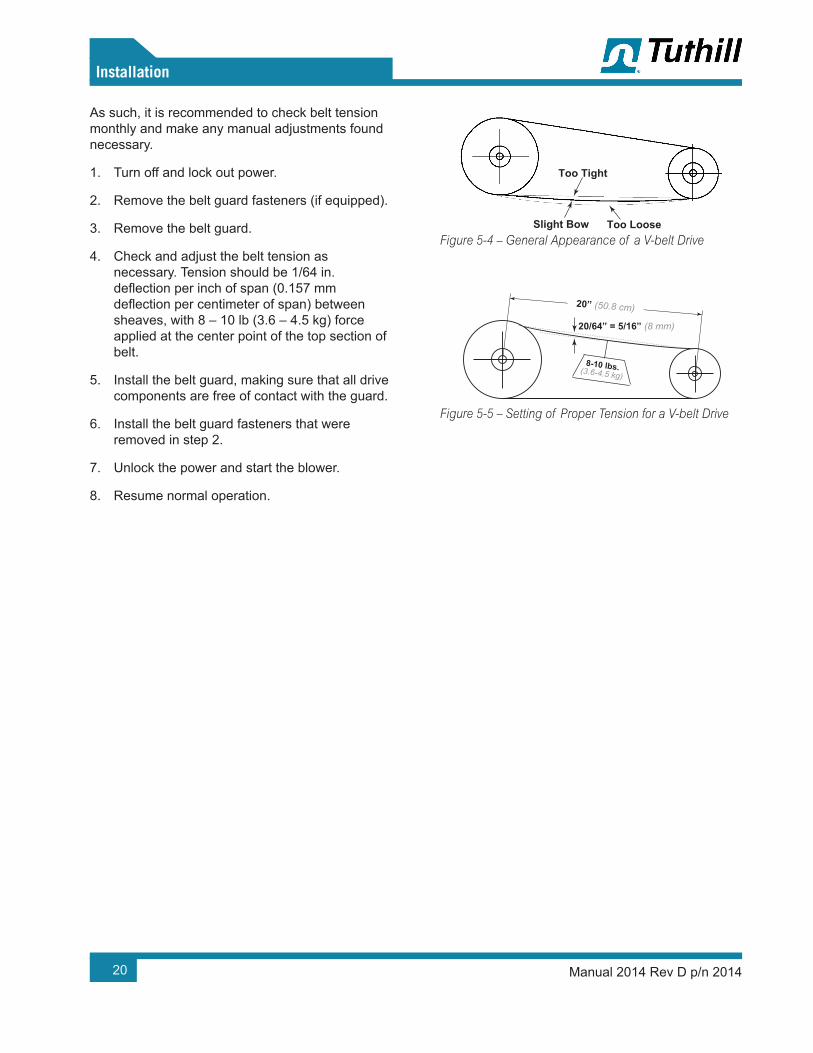
Proper belt tension is essential to long blower life. Figure 5-4, Figure 5-5, and the following procedure are provided to aid in field-adjusting V-belts (when the blower is so equipped) for maximum performance. A visual inspection of the V-belt drive should yield the appearance shown in Figure 5-4.
Factors outside the control of the belt tensioning system used on an individual blower package assembly, such as environmental factors and quality of the belts installed, may contribute to decreased belt life. Such factors can cause wear of the belts beyond the ability of the tensioning system to compensate.
20
05Installation
Manual 2014 Rev D p/n 2014
As such, it is recommended to check belt tension monthly and make any manual adjustments found necessary.
1. Turn off and lock out power.
2. Remove the belt guard fasteners (if equipped).
3. Remove the belt guard.
4. Check and adjust the belt tension as necessary. Tension should be 1/64 in. deflection per inch of span (0.157 mm deflection per centimeter of span) between sheaves, with 8 – 10 lb (3.6 – 4.5 kg) force applied at the center point of the top section of belt.
5. Install the belt guard, making sure that all drive components are free of contact with the guard.
6. Install the belt guard fasteners that were removed in step 2.
7. Unlock the power and start the blower.
8. Resume normal operation.
Too Tight
Slight Bow Too Loose
20/64” = 5/16” (8 mm)
20” (50.8 cm)
8-10 lbs.(3.6-4.5 kg)
Figure 5-4 – General Appearance of a V-belt Drive
Too Tight
Slight Bow Too Loose
20/64” = 5/16” (8 mm)
20” (50.8 cm)
8-10 lbs.(3.6-4.5 kg)
Figure 5-5 – Setting of Proper Tension for a V-belt Drive

21
05Installation
Manual 2014 Rev D p/n 2014
V-Belt Troubleshooting
PROBLEM POSSIBLE CAUSES SOLUTION
Belts slip (sidewalls glazed) Not enough tension Replace belts; apply proper tension.
Drive squealsShock load Apply proper tension.Not enough arc of contact Increase center distance.Heavy starting load Increase belt tension.
Belt(s) turned over
Broken cord caused by prying on sheave Replace set of belts and install correctly.
Overloaded drive Redesign drive.Impulse loads Apply proper tension.Misalignment of sheave and shaft Re-align drive.Worn sheave grooves Replace sheaves.
Excessive belt vibration
Check drive design.
Check equipment for solid mounting.
Consider use of banded belts.Mismatched belts New belts installed with old belts Replace belts in matched sets only.
Breakage of belt(s)
Shock loads Apply proper tension; recheck drive.
Heavy starting loadsApply proper tension; recheck drive.
Use compensator starting.Belt pried over sheaves Replace set of belts correctly.Foreign objects in drives Provide drive guard.
Rapid belt wear
Sheave grooves worn Replace sheaves.Sheave diameter too small Redesign drive.Mismatched belts Replace with matched belts.Drive overloaded Redesign drive.Belt slips Increase tension.Sheaves misaligned Align sheaves.Oil or heat condition Eliminate oil. Ventilate drive.

22
05Installation
Manual 2014 Rev D p/n 2014
MOTOR AND ELECTRICAL CONNECTIONS
WARNING!The motor and connections shall be protected to assure that product and environmental condensation does not come in contact with the electrical connections.
It is the responsibility of the installer to assure that the motor is in compliance with the latest edition of IEC 60204-1 and all electrical connections performed per IEC 60204-1, this includes over current protection.
Wire the motor and other electrical devices, such as solenoid valves and temperature switch, to the proper voltage and amperage as indicated on the nameplate of the component being wired. Turn the blower by hand after wiring is completed to determine that there are no obstructions and that the blower turns freely. Then, momentarily start the blower to check the direction of rotation.
Figure 4-2 shows direction of airflow in relation to rotor rotation. The airflow direction can be reversed by reversing the appropriate motor leads.

23Manual 2014 Rev D p/n 2014
GENERAL
DANGER!The blower is not intended to be used with explosive products or in explosive environments. The blower is not intended to be used in applications that include hazardous and toxic gases. Consult the factory for support.
WARNING!Do not operate without guards in place.
WARNING!Maximum operating speed: Table 4-2 on page 9 states the maximum operating speed in RPM (rotations per minute), the maximum pressure differential, maximum vacuum and maximum temperature rise. Do not exceed these limits.
Before starting the blower for the first time under power, recheck the installation thoroughly to reduce the likelihood of difficulties. Use the following checklist as a guide, but consider any other special conditions in your installation.
1. Be certain no bolts, rags, or dirt have been left in blower.
2. Be certain that inlet piping is free of debris. If an open outdoor air intake is used, be sure the opening is clean and protected by an inlet filter. This also applies to indoor use.
3. If installation is not recent, check blower leveling, drive alignment, belt tension, and tightness of all mounting bolts.
4. Be certain the proper volume of oil is in the oil reservoir chambers.
5. Be certain the driving motor is properly lubricated and connected through suitable electrical overload devices.
6. With electrical power off and locked out to prevent accidental starting, rotate the blower shaft several times by hand to make sure the blower is rotating freely. Unevenness or tight spots are indicators of a condition that should be corrected before progressing.
7. Check motor rotation by momentarily pushing the START button and then checking the flow direction of the blower. Reverse the motor connections if the flow is in the wrong direction.
OPERATION
06

24
06Operation
Manual 2014 Rev D p/n 2014
Carry out initial operation under “no load” conditions by opening all valves and venting the discharge to the atmosphere, if possible. Then, start the motor briefly, listen for unusual noises, and make sure the blower coasts freely to a stop. If no problem appears, repeat this check and let the motor run slightly longer. If any questions exist, investigate before proceeding.
Assuming all tests are satisfactory, the blower will now be ready for continuous full-load operation. During the first several days, check periodically to make sure all conditions remain acceptable and
steady. These checks may be particularly important if the blower is part of a process system where conditions may vary. At the first opportunity, stop the blower and clean or remove the inlet filter. Also recheck leveling, coupling alignment or belt tension, and mounting bolts for tightness
START-UP CHECKLIST
Tuthill recommends that these start-up procedures be followed in sequence and checked off ( ) in the boxes provided in any of the following cases.
• During initial installation• After any shutdown period
• After maintenance work has been performed• After booster has been moved to a new location
DATES CHECKED:
Check the unit for proper lubrication. Proper oil level is critical. See Lubrication on page 15. See Recommended Lubricants on page 40 for information on acceptable lubricants for the product.
Check the V-belt drive for proper belt alignment and tension.
Carefully turn the rotors by hand to be certain they do not bind.
WARNING!Disconnect power. Make certain power is off and locked out before touching any rotating element of the booster, motor, or drive components.
“Bump” the unit with the motor to check rotation (counterclockwise when facing the shaft) and to be certain it turns freely and smoothly.
Start the unit and operate it for 30 minutes at no load. During this time, feel the cylinder for hot spots. If minor hot spots occur.
Apply the load and observe the operation of the booster for 1 hour.
If minor malfunctions occur, discontinue operation and see Troubleshooting on page 36.

25
06Operation
Manual 2014 Rev D p/n 2014
OPERATING
The upper temperature limit for blower operation is measured in the exhaust gas stream with a low-mass thermocouple. When this temperature limit switch is installed, as the temperature exceeds the predetermined temperature, the blower motor will stop and cannot be restarted until the temperature drops below the trip setting of the temperature switch.
DANGER!The blower is not intended to be used with explosive products or in explosive environments. The blower is not intended to be used in applications that include hazardous and toxic gases. Consult the factory for support.
WARNING!The blower can generate excessive noise. Hearing protection is required while the unit is in operation.
WARNING!Physical harm may occur if human body parts are in contact or exposed to the process vacuum. Assure that all connections are protected from human contact.
WARNING!If rated vacuum or pressure levels are exceeded, process fluids will migrate to other parts of the blower and system.
CAUTION!Do not touch hot surfaces.
The upper limit of the blower operation is 445° F (229° C). Do not touch the blower while it is in operation and assure blower is cool when not in operation.
CAUTION!Use of a thermowell insulates the thermocouple. Invalid and delayed readings will result. This can result in ineffective protection devices.
The upper temperature limits are not intended for continuous operation. Consult with factory for detailed information assistance.
STOPPING
CAUTION!Do not stop the blower if there are high outlet pressures in the outlet piping. Unload the outlet piping prior to shutting down the blower.
Stop the blower by turning off the motor. Isolate the blower from the vacuum system and vent the blower to atmosphere. Turn off the cooling water, if the blower is water cooled. Stop the backing pump. See the component instruction manual.

26
06Operation
Manual 2014 Rev D p/n 2014
RECOMMENDED SHUTDOWN PROCEDURE TO MINIMIZE RISK OF FREEZING OR CORROSION
When an air piping system has high humidity or moisture, water condensation can occur after the blower is shut down and it begins to cool. Condensation creates an environment favorable to corrosion of the iron internal surfaces and to ice formation in cold weather. Both conditions can close the operating clearances, causing the blower to fail upon future start-up.
The following shutdown procedure minimizes the risk of moisture condensation, corrosion, and freezing.
Care must be taken so as not to overload or overheat the blower during this procedure.
1. Isolate the blower from the moist system piping, allowing the blower to intake atmospheric air. Operate the blower under a slight load, allowing the blower to heat within safe limits. The heat generated by the blower will quickly evaporate residual moisture.
2. For carpet cleaning applications, after the work is completed, allow the blower to run 3 – 5 minutes with the suction hose and wand attached. The suction hose and wand will provide enough load to the blower to evaporate the moisture quickly.
3. For extended shutdown, inject a small amount of a light lubricating oil such as 3-in-One® or a spray lubricant such as WD-40® into the inlet of the blower just before shutdown (3-in-One and WD-40 are registered trademarks of WD-40 Company). The lubricant will provide an excellent protective coating on the internal surfaces. If using a spray lubricant, take care to prevent the applicator tube from getting sucked into the blower. The applicator tube will damage the blower, likely to a degree where repair would be required.
4. If the blower is being taken out of commission for an extended period of time, see Long-Term Storage on page 29.

27
07
Manual 2014 Rev D p/n 2014
GENERAL
Regular inspection of the blower and its installation, along with complete checks on operating conditions, will pay dividends in added life and usefulness. Also, service the drive per the manufacturer’s instructions and lubricate the coupling or check the belt drive tension.
DANGER!The blower and parts may contain hazardous media. Assure that pump and parts are evacuated of hazardous media prior to servicing.
CAUTION!The electrical service must be isolated and de-energized prior to maintenance. Apply appropriate procedures to assure electrical supply is de-energized and cannot be inadvertently energized during maintenance.
Assure piping and product is isolated prior to maintenance of blower. Apply appropriate procedures to assure piping and product is isolated and that inadvertent opening of valves cannot occur during maintenance.
CAUTION!During routine maintenance, inspect and assure that guards are in place and secure.
Pay special attention to lubrication of timing gears and bearings according to the information in Lubrication on page 15.
When a blower is taken out of service, it may require internal protection against rusting or corrosion. The need for such protection must be a matter of judgment based on existing conditions as well as length of downtime. Under atmospheric conditions producing rapid corrosion, protect the blower immediately. See Long-Term Storage on page 29.
MAINTENANCE
28 Manual 2014 Rev D p/n 2014
07 Maintenance
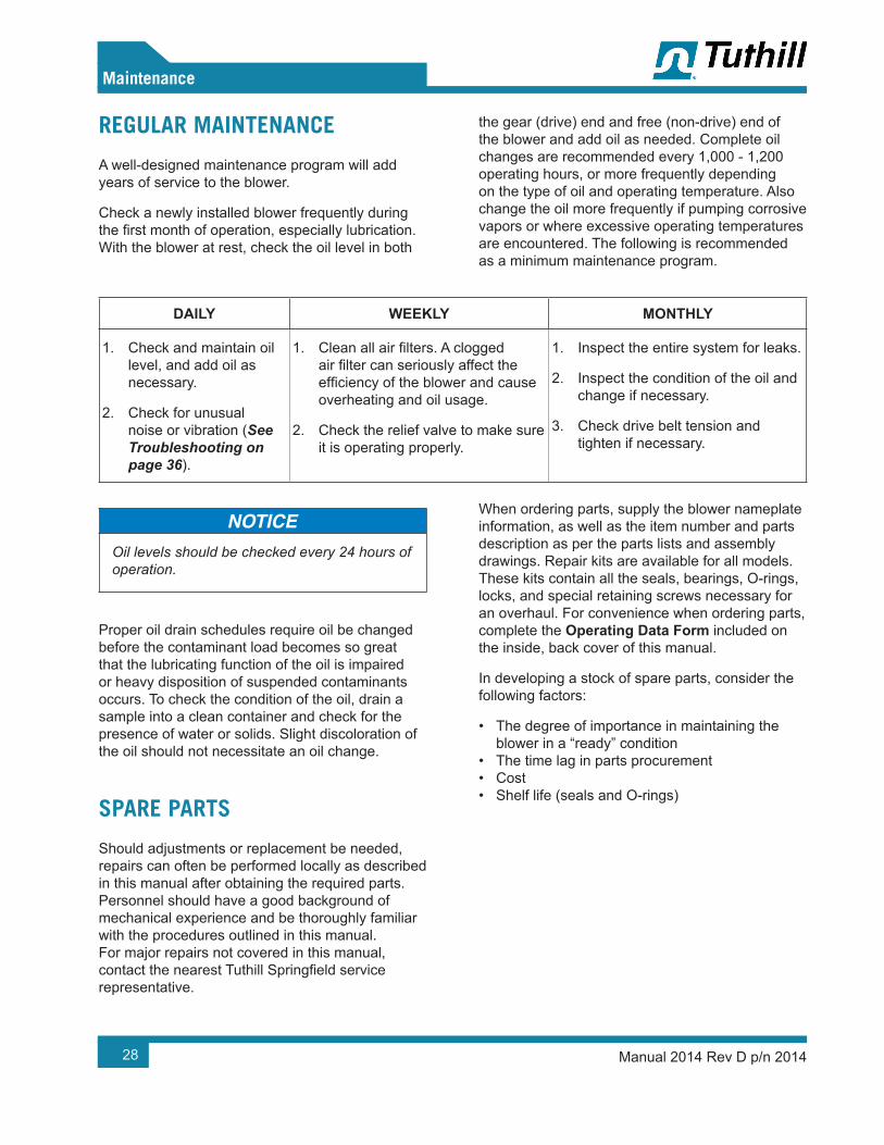
REGULAR MAINTENANCE
A well-designed maintenance program will add years of service to the blower.
Check a newly installed blower frequently during the first month of operation, especially lubrication. With the blower at rest, check the oil level in both
the gear (drive) end and free (non-drive) end of the blower and add oil as needed. Complete oil changes are recommended every 1,000 - 1,200 operating hours, or more frequently depending on the type of oil and operating temperature. Also change the oil more frequently if pumping corrosive vapors or where excessive operating temperatures are encountered. The following is recommended as a minimum maintenance program.
DAILY WEEKLY MONTHLY
1. Check and maintain oil level, and add oil as necessary.
2. Check for unusual noise or vibration (See Troubleshooting on page 36).
1. Clean all air filters. A clogged air filter can seriously affect the efficiency of the blower and cause overheating and oil usage.
2. Check the relief valve to make sure it is operating properly.
1. Inspect the entire system for leaks.
2. Inspect the condition of the oil and change if necessary.
3. Check drive belt tension and tighten if necessary.
Oil levels should be checked every 24 hours of operation.
Proper oil drain schedules require oil be changed before the contaminant load becomes so great that the lubricating function of the oil is impaired or heavy disposition of suspended contaminants occurs. To check the condition of the oil, drain a sample into a clean container and check for the presence of water or solids. Slight discoloration of the oil should not necessitate an oil change.
SPARE PARTS
Should adjustments or replacement be needed, repairs can often be performed locally as described in this manual after obtaining the required parts. Personnel should have a good background of mechanical experience and be thoroughly familiar with the procedures outlined in this manual. For major repairs not covered in this manual, contact the nearest Tuthill Springfield service representative.
When ordering parts, supply the blower nameplate information, as well as the item number and parts description as per the parts lists and assembly drawings. Repair kits are available for all models. These kits contain all the seals, bearings, O-rings, locks, and special retaining screws necessary for an overhaul. For convenience when ordering parts, complete the Operating Data Form included on the inside, back cover of this manual.
In developing a stock of spare parts, consider the following factors:
• The degree of importance in maintaining the blower in a “ready” condition
• The time lag in parts procurement• Cost• Shelf life (seals and O-rings)

29
07Maintenance
Manual 2014 Rev D p/n 2014
FACTORY SERVICE AND REPAIR
With proper care, Tuthill Springfield blowers will give years of reliable service. The parts are machined to close tolerances and require special tools by mechanics who are skilled at this work. Should major repairs become necessary, contact the factory for the location of the nearest service facility.
Current regulations require Material Safety Data Sheet to be completed and forwarded to Tuthill Corporation on any unit being returned for any reason which has been handling or involved with hazardous gases or materials. This is for the protection of the employees of Tuthill Corporation who are required to perform service on this equipment. Failure to do so will result in service delays.
When returning a blower to the factory for repair, under warranty, please note the factory will not accept any unit that arrives without authorization. Contact Customer Service for return authorization.
LONG-TERM STORAGE
Any time the blower will be stored for an extended period of time, make sure it is protected from corrosion by following this procedure:
1. Spray the interior (lobes, housing, and end plates) with rust preventative. Repeat as conditions dictate and on an at least a yearly basis.
2. Fill both end covers completely full of oil.
3. Firmly attach a prominent tag stating that the end covers are full of oil and must be drained and refilled to proper levels before start-up.
4. Apply a rust-preventative grease to the drive shaft.
5. Spray all exposed surfaces, including the inlet and discharge flanges, with rust preventative.
6. Seal the inlet, discharge, and vent openings. It is not recommended that the blower be set in place, piped to the system, and allowed to remain idle for a prolonged amount of time. If any component is left open to the atmosphere, the rust preventative will escape and lose its effectiveness.
7. During storage, make sure the blower does not experience excessive vibration.
8. Attach a desiccant bag to one of the covers to prevent condensation from occurring inside the blower. Make sure any desiccant bag (or bags) is attached to the covers so that they will be removed before start-up of the blower.
9. Store the blower in an air conditioned and heated building if possible. If air conditioned and heated storage is not possible, make conditions as dry as possible.
10. If possible, rotate the drive shaft by hand at least monthly to prevent seals from setting in one position.
30 Manual 2014 Rev D p/n 2014
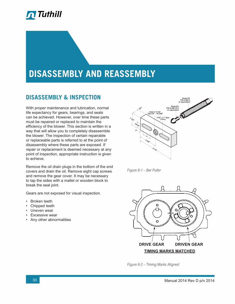
DISASSEMBLY & INSPECTION
With proper maintenance and lubrication, normal life expectancy for gears, bearings, and seals can be achieved. However, over time these parts must be repaired or replaced to maintain the efficiency of the blower. This section is written in a way that will allow you to completely disassemble the blower. The inspection of certain repairable or replaceable parts is referred to at the point of disassembly where these parts are exposed. If repair or replacement is deemed necessary at any point of inspection, appropriate instruction is given to achieve.
Remove the oil drain plugs in the bottom of the end covers and drain the oil. Remove eight cap screws and remove the gear cover. It may be necessary to tap the sides with a mallet or wooden block to break the seal joint.
Gears are not exposed for visual inspection.
• Broken teeth• Chipped teeth• Uneven wear• Excessive wear• Any other abnormalities
1”
2 5/8”
5 1/4”
2”
15/16”
1 7/8”
3/4”
Drill Ø 11/16”Tap 3/4” - 16 UNF
7/16” × 1” Slot(Thru)
Snap-OnP/N CJ66-15-3or equivalent
Snap-OnP/N CJ83-3
or equivalent
Figure 8-1 – Bar Puller
DRIVE GEAR DRIVEN GEAR
DRIVE GEAR DRIVEN GEAR
TIMING MARKS MATCHED
TIMING MARKS ADVANCED 3 TEETH(Reference Marks Aligned)
Figure 8-2 – Timing Marks Aligned
DISASSEMBLY AND REASSEMBLY
08

31
08
Disassembly and Reassembly
Manual 2014 Rev D p/n 2014
DRIVE GEAR DRIVEN GEAR
DRIVE GEAR DRIVEN GEAR
TIMING MARKS MATCHED
TIMING MARKS ADVANCED 3 TEETH(Reference Marks Aligned)
Figure 8-3 – Timing Marks Advanced Three Teeth
WARNING!Before performing any repair or replacement, disconnect and lock out power.
DISASSEMBLY OF BLOWER
1. Remove the blower from the installation, and drain lubricant from both ends by removing the magnetic drain plugs. Mark the end plates, covers and housing so they can be reassembled in their original positions.
2. Remove the cap screws from the drive end cover. Use a beveled chisel and hammer to remove the cover.
3. Remove the cap screw, washer and oil slinger.
4. Remove the cap screw and bearing retainer plates. Note the location and sequence of the wave springs and spacers as they are removed.
5. Attach the bar pullers as shown in Figure 8-1 to each bearing bore and pull end plate.
6. Remove the cap screws and gear end cover.
7. Remove the gear lock bolts and washers.
8. Align the timing marks on the gears (see Figure 8-3). Rotate the drive gear clockwise approximately three teeth, and mark a matching reference line on each gear as shown in Figure 8-4. This gear position is necessary so rotors will clear and not jam. Do not allow the gears to move from the matched reference line while pulling. Use a light rocking motion to make sure that the lobes have not jammed. Remove the driven gear first, and then remove the drive gear.
Failure to properly pull this gear could result in damage to rotor keyway or a bent rotor shaft. Never use excessive force.
9. Remove the cap screws and bearing retainer plates.
10. Use a bar puller attached to the bearing bore to push one rotor at a time from the end plate. Keep the rotor lobes in a vertical position while removing.
11. Using a mallet, tap the end plate from the housing.
12. Tap out the bearings and seals.
13. Remove the seal rings from the rotor shaft sleeves.
14. Inspect all parts for wear.
ASSEMBLY OF BLOWER
The assembly procedure is generally the same for all series, but notations are made where there are differences.
32
08
Disassembly and Reassembly
Manual 2014 Rev D p/n 2014
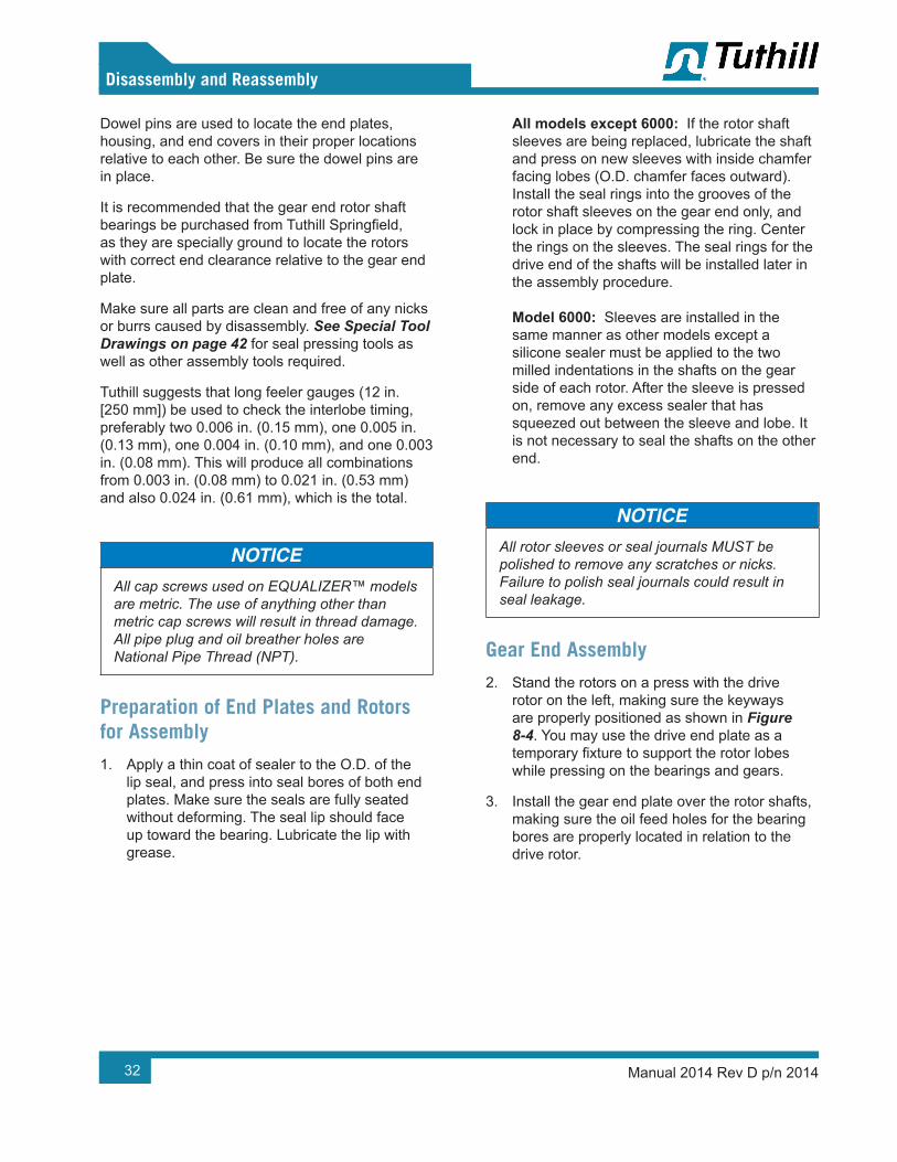
Dowel pins are used to locate the end plates, housing, and end covers in their proper locations relative to each other. Be sure the dowel pins are in place.
It is recommended that the gear end rotor shaft bearings be purchased from Tuthill Springfield, as they are specially ground to locate the rotors with correct end clearance relative to the gear end plate.
Make sure all parts are clean and free of any nicks or burrs caused by disassembly. See Special Tool Drawings on page 42 for seal pressing tools as well as other assembly tools required.
Tuthill suggests that long feeler gauges (12 in. [250 mm]) be used to check the interlobe timing, preferably two 0.006 in. (0.15 mm), one 0.005 in. (0.13 mm), one 0.004 in. (0.10 mm), and one 0.003 in. (0.08 mm). This will produce all combinations from 0.003 in. (0.08 mm) to 0.021 in. (0.53 mm) and also 0.024 in. (0.61 mm), which is the total.
All cap screws used on EQUALIZER™ models are metric. The use of anything other than metric cap screws will result in thread damage. All pipe plug and oil breather holes are National Pipe Thread (NPT).
Preparation of End Plates and Rotors for Assembly
1. Apply a thin coat of sealer to the O.D. of the lip seal, and press into seal bores of both end plates. Make sure the seals are fully seated without deforming. The seal lip should face up toward the bearing. Lubricate the lip with grease.
All models except 6000: If the rotor shaft sleeves are being replaced, lubricate the shaft and press on new sleeves with inside chamfer facing lobes (O.D. chamfer faces outward). Install the seal rings into the grooves of the rotor shaft sleeves on the gear end only, and lock in place by compressing the ring. Center the rings on the sleeves. The seal rings for the drive end of the shafts will be installed later in the assembly procedure. Model 6000: Sleeves are installed in the same manner as other models except a silicone sealer must be applied to the two milled indentations in the shafts on the gear side of each rotor. After the sleeve is pressed on, remove any excess sealer that has squeezed out between the sleeve and lobe. It is not necessary to seal the shafts on the other end.
All rotor sleeves or seal journals MUST be polished to remove any scratches or nicks. Failure to polish seal journals could result in seal leakage.
Gear End Assembly
2. Stand the rotors on a press with the drive rotor on the left, making sure the keyways are properly positioned as shown in Figure 8-4. You may use the drive end plate as a temporary fixture to support the rotor lobes while pressing on the bearings and gears.
3. Install the gear end plate over the rotor shafts, making sure the oil feed holes for the bearing bores are properly located in relation to the drive rotor.

33
08
Disassembly and Reassembly
Manual 2014 Rev D p/n 2014
Drive DrivenDRIVE DRIVEN
Figure 8-4 – Keyway Position
OTE: N Two oil feed holes for each bearing bore must always be at the top when the assembled unit is standing on its feet. Units can only be assembled for top drive, left drive, or right drive.
The seal rings should glide into their respective bores with ease.
4. Lubricate the shafts and press the double row ball bearings onto the shafts and into the end plate bores. Use the bearing pressing tool shown in Special Tool Drawings on page 42.
CAUTION!These bearings have flush ground faces and should be installed with manufacturer numbers up (toward gear). If no numbers appear on either side, look for a black dot (acid mark) on the inner race. Install with dot up. Do not use bearings that have not been flush ground to within a .001" (.025 mm) tolerance.
5. Install the bearing retainer rings and secure with cap screws. At this time, use feeler gauges to check the clearance between the face of the end plate and the rotor lobes. See Parts List on page 44 and Assembly Drawings on page 47 for gear end clearance. If clearances are not within specifications, recheck the parts to find the cause of the incorrect clearances before proceeding.
6. Install the keys in the rotor shaft keyways. Tight fits are required.
7. Lubricate the shafts and keys, and press the drive gear (right hand helix) on the drive rotor. To install the driven gear, align the reference marks as shown in Figure 8-3. Tap the gear with a mallet to start, and then press the gear until seated.
OTE: N All timing gears must be used in sets as they are matched and serially numbered.
8. Install the gear washers and secure with cap screws using a few drops of Loctite® 242 (removable Threadlocker) on each screw.
9. Remove the assembly from the press and stand it on a workbench with the gears down. Place blocks under the end plate to prevent the assembly from falling over. The drive gear should remain on the left side.
10. Install the rotor housing and secure temporarily with two cap screws evenly spaced.
11. Check clearances between the end of the lobes and housing using a flat bar and feeler gauges or a depth micrometer. See Parts List on page 44 and Assembly Drawings on page 47 for drive end clearances.

34
08
Disassembly and Reassembly
Manual 2014 Rev D p/n 2014
END COVEREND COVER
FLANGE SIDEFLANGE SIDEOF INNER RACEOF INNER RACE
For Model 4500, install bearing so that flange For Model 4500, install bearing so that flange side of inner race faces outward.side of inner race faces outward.
(shown)(shown)46004600
45004500
HOUSINGHOUSING
Figure 8-5 – Bearing Race
Drive End Assembly
12. Repeat step 3 and step 4 to assemble the drive end plate and temporarily secure with two cap screws evenly spaced.
OTE: N 4500 Models: Install free end spacers on shaft (Item 123)
13. Lubricate the shafts and install roller bearings on 4600 models. On 6000 models, the drive rotor bearing is a larger bearing than the driven rotor bearing.
OTE: N The inner races of all roller bearings have a flange on one side only. This flange must face inward (see Figure 8-5). For 4500 models, the inner race flange must face outward.
14. 4600 Models: Install one wave spring on the drive rotor, and install two wave springs with spacer between on the driven rotor.
OTE: N 4500 models have no wave springs to install.
6000 Models: Install two wave springs with spacer between on both rotors.
Secure with the retainer plate and cap screws.
15. Install the spring pin in the driven rotor, oil slinger, and washer. Secure with cap screw.
16. Apply a thin coat of sealer to the O.D. of the drive shaft seal and press into the end cover bore. The lip must face inward.
17. Remove the temporary screws, and then place a bead of silicone sealer around the perimeter of the end plate. Carefully slide the cover over the drive shaft. Make sure the dowels are in place. Secure with cap screws. Lay the assembly down with the drive gear on the left for timing.
Adjusting Rotor Interlobe Clearance
18. The driven gear is made of two pieces. The outer gear shell is fastened to the inner hub with four cap screws and located with two dowel pins. A laminated shim, made up of 0.003 in. (0.076 mm) laminations, separates the hub and the shell. Removing or adding shim laminations moves the gear shell axially relative to the inner hub. Being a helical gear, it rotates as it is moved in or out and the driven rotor turns with it, thus changing the clearance between the rotor lobes. Changing the shim thickness 0.014 in. (0.36 mm) on a 6000 model will change the interlobe clearance approximately 0.005 in. (0.13 mm). On a 4600 model, it would take approximately 0.012 in. (0.30 mm) shims to produce the same change. EXAMPLE: See Figure 8-6, check the clearance on a 6000 model at AA (right-hand reading) and BB (left-hand reading). If the AA reading is 0.017 in. (0.43 mm) and BB reading is 0.004 in. (0.10 mm), by removing 0.018 in. (0.46 mm) of shims, the readings should then read: AA 0.011 in. (0.28 mm) and BB 0.010 in. (0.25 mm).

35
08
Disassembly and Reassembly
Manual 2014 Rev D p/n 2014
To determine the amount of shim to add or remove, subtract the smaller reading from the larger and multiply the result by: 1.2 for Model 4600: 0.017 − 0.004 = 0.013 in. (0.33 mm) × 1.2 = 0.0156 in. (0.396 mm) or 0.015 in. (0.38 mm) 1.4 for Model 6000: 0.017 − 0.004 = 0.013 in. (0.33 mm) × 1.4 = 0.0182 in. (0.462 mm) or 0.018 in. (0.46 mm)
Round off the amount the closest increment of shims available: 0.006 in., 0.009 in., 0.012 in., etc.
To determine whether to add or remove shim: If the right side reading is higher than the left side, remove this amount. If the right side reading is lower, then add this amount. When removing gear shell from the driven gear, it is not necessary to remove the gear lock bolt. After completing the timing of the lobes, bend over the lock tabs on the four gear cap screws.
A
B B
B
A
B
AA
A A
B
A
BB
A
B
LONG FEELER GAUGE
LONG FEELER GAUGE
RECORD A-AREADING HERE
RECORD A-AREADING HERE
RECORD B-BREADING HERE
3 LOBE
2 LOBE
RECORD B-BREADING HERE
B B
BB
B
BB
B
B
B
B
B
A
A
AA
A
A
A
A
A
A
A
ADRIVE
DRIVEN DRIVEDRIVEN
Figure 8-6 – Checking Rotor Interlobe Clearance
19. Install the gear cover using the same method as was used to install the drive cover (step 18).
20. Install the mounting feet, and secure with cap screws and washers.
21. Before putting the blower into operation, follow the instructions in Installation on page 11 and Operation on page 23. Observe the oil level frequently during the initial hours of operation. A badly installed or damaged oil seal will result in oil loss.

36 Manual 2014 Rev D p/n 2014
Although Tuthill Springfield boosters are well designed and manufactured, problems may occur due to normal wear and the need for readjustment. The following chart lists symptoms that may occur along with probable causes and remedies.
SYMPTOM PROBABLE CAUSE REMEDIES
Loss of oil
Gear housing not tightened properly Tighten gear housing bolts.
Lip seal failure Disassemble and replace lip seal.
Insufficient sealant Remove gear housing and replace sealant. See Disassembly of Blower on page 31.
Loose drain plug Tighten drain plug.
Excessive bearing or gear wear
Improper lubrication Correct oil level. Replace dirty oil. See Lubrication on page 15.
Excessive belt tension Check belt manufacturer’s specifications for tension and adjust accordingly.
Coupling misalignment Check carefully. Re-align if necessary.
Lack of volume
Slipping belts Check belt manufacturer’s specifications for tension and adjust accordingly.
Worn lobe clearances Check for proper clearances. See Assembly Clearances on page 38.
Speed too low Increase blower speed within limits.
Obstruction in piping Check system to ensure an open flow path.
Knocking
Blower out of time Re-time.
Distortion due to improper mounting or pipe strains
Check mounting alignment and relieve pipe strains.
Excessive pressure differential
Reduce to manufacturer’s recommended pressure. Examine relief valve and reset if necessary.
Worn gears Replace timing gears. See Disassembly of Blower on page 31.
09TROUBLESHOOTING
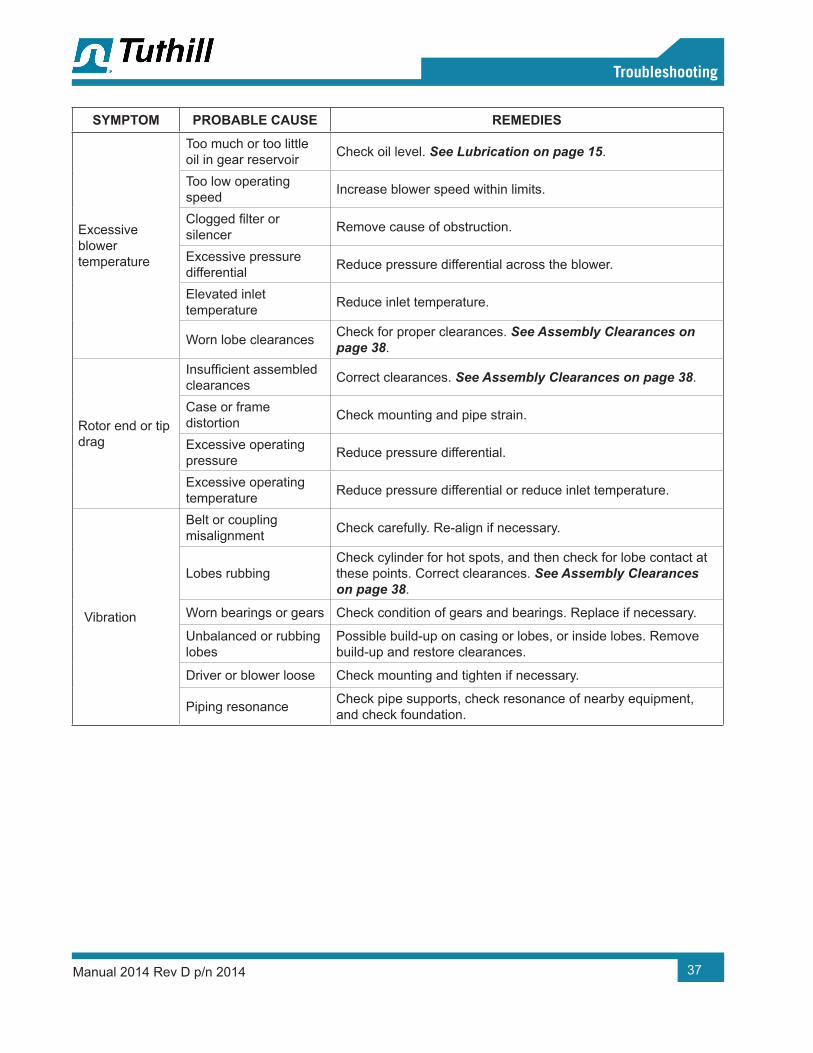
37
09
Troubleshooting
Manual 2014 Rev D p/n 2014
SYMPTOM PROBABLE CAUSE REMEDIES
Excessive blower temperature
Too much or too little oil in gear reservoir Check oil level. See Lubrication on page 15.
Too low operating speed Increase blower speed within limits.
Clogged filter or silencer Remove cause of obstruction.
Excessive pressure differential Reduce pressure differential across the blower.
Elevated inlet temperature Reduce inlet temperature.
Worn lobe clearances Check for proper clearances. See Assembly Clearances on page 38.
Rotor end or tip drag
Insufficient assembled clearances Correct clearances. See Assembly Clearances on page 38.
Case or frame distortion Check mounting and pipe strain.
Excessive operating pressure Reduce pressure differential.
Excessive operating temperature Reduce pressure differential or reduce inlet temperature.
Vibration
Belt or coupling misalignment Check carefully. Re-align if necessary.
Lobes rubbingCheck cylinder for hot spots, and then check for lobe contact at these points. Correct clearances. See Assembly Clearances on page 38.
Worn bearings or gears Check condition of gears and bearings. Replace if necessary.
Unbalanced or rubbing lobes
Possible build-up on casing or lobes, or inside lobes. Remove build-up and restore clearances.
Driver or blower loose Check mounting and tighten if necessary.
Piping resonance Check pipe supports, check resonance of nearby equipment, and check foundation.

38 Manual 2014 Rev D p/n 2014
MODELLOBE TO END PLATES LOBE TO CASING INTERLOBE
GEAR END DRIVE END TIP-DOWEL TIP-PORT MINIMUM
4504 0.004 – 0.008 in. (0.10 – 0.20 mm)
0.005 – 0.009 in. (0.13 – 23 mm)
0.007 – 0.011 in. (0.18 – 0.28 mm)
0.009 – 0.013 in. (0.23 – 0.33 mm)
0.008 – 0.012 in. (0.20 – .30 mm)
4506 0.004 - 0.008 in. (0.10 – 0.20 mm)
0.006 – 0.010 in. (0.10 – 0.25 mm)
0.007 – 0.011 in. (0.18 – 0.28 mm)
0.009 – 0.013 in. (0.23 – 0.33 mm)
0.008 – 0.012 in. (0.20 – 0.30 mm)
4509 0.004 - 0.008 in. (0.10 – 0.20 mm)
0.009 – 0.013 in. (0.23 – 0.33 mm)
0.007 – 0.011 in. (0.18 – 0.28 mm)
0.009 – 0.013 in. (0.23 – 0.33 mm)
0.008 – 0.012 in. (0.20 – 0.30 mm)
4512 0.004 - 0.008 in. (0.10 – 0.20 mm)
0.012 – 0.016 in. (0.30 – 0.41 mm)
0.007 – 0.011 in. (0.18 – 0.28 mm)
0.009 – 0.013 in. (0.23 – 0.33 mm)
0.008 – 0.012 in. (0.20 – 0.30 mm)
4604 0.004 - 0.008 in. (0.10 – 0.20 mm)
0.005 – 0.009 in. (0.13 – 0.23 mm)
0.007 – 0.011 in. (0.18 – 0.28 mm)
0.009 – 0.013 in. (0.23 – 0.33 mm)
0.008 – 0.012 in. (0.20 – 0.30 mm)
4606 0.004 - 0.008 in. (0.10 – 0.20 mm)
0.006 – 0.010 in. (0.10 – 0.25 mm)
0.007 – 0.011 in. (0.18 – 0.28 mm)
0.009 – 0.013 in. (0.23 – 0.33 mm)
0.008 – 0.012 in. (0.20 – 0.30 mm)
4609 0.004 - 0.008 in. (0.10 – 0.20 mm)
0.009 – 0.013 in. (0.23 – 0.33 mm)
0.007 – 0.011 in. (0.18 – 0.28 mm)
0.009 – 0.013 in. (0.23 – 0.33 mm)
0.008 – 0.012 in. (0.20 – 0.30 mm)
4612 0.004 - 0.008 in. (0.10 – 0.20 mm)
0.012 – 0.016 in. (0.30 – 0.41 mm)
0.007 – 0.011 in. (0.18 – 0.28 mm)
0.009 – 0.013 in. (0.23 – 0.33 mm)
0.008 – 0.012 in. (0.20 – 0.30 mm)
6012 0.005 - 0.009 in. (0.13 – 0.23 mm)
0.014 – 0.020 in. (0.36 – 0.51 mm)
0.008 – 0.013 in. (0.20 – 0.33 mm)
0.011 – 0.016 in. (0.28 – 0.41 mm)
0.012 – 0.016 in. (0.30 – 0.41 mm)
6016 0.005 - 0.009 in. (0.13 – 0.23 mm)
0.018 – 0.024 in. (0.46 – 0.61 mm)
0.008 – 0.013 in. (0.20 – 0.33 mm)
0.011 – 0.016 in. (0.28 – 0.41 mm)
0.012 – 0.016 in. (0.30 – 0.41 mm)
6024 0.005 - 0.009 in. (0.13 – 0.23 mm)
0.018 – 0.024 in. (0.46 – 0.61 mm)
0.011 – 0.016 in. (0.28 – 0.41 mm)
0.014 – 0.019 in. (0.36 – 0.48 mm)
0.012 – 0.016 in. (0.30 – 0.41 mm)
ASSEMBLY CLEARANCES
10
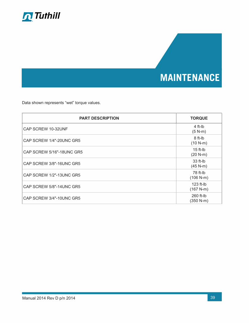
39Manual 2014 Rev D p/n 2014
Data shown represents “wet” torque values.
PART DESCRIPTION TORQUE
CAP SCREW 10-32UNF 4 ft-lb (5 N-m)
CAP SCREW 1/4"-20UNC GR5 8 ft-lb (10 N-m)
CAP SCREW 5/16"-18UNC GR5 15 ft-lb (20 N-m)
CAP SCREW 3/8"-16UNC GR5 33 ft-lb (45 N-m)
CAP SCREW 1/2"-13UNC GR5 78 ft-lb (106 N-m)
CAP SCREW 5/8"-14UNC GR5 123 ft-lb (167 N-m)
CAP SCREW 3/4"-10UNC GR5 260 ft-lb (350 N-m)
11MAINTENANCE

40 Manual 2014 Rev D p/n 2014
RECOMMENDED LUBRICANTS
12RECOMMENDED LUBRICANTS FOR TUTHILL BLOWER AND VACUUM BOOSTERS
Tuthill positive displacement blowers and vacuum boosters require proper lubrication for bearings, seals and gears to operate effectively and efficiently. Oil is distributed from the oil reservoir to the critical components by means of oil slingers that are attached to the rotor shaft. In certain models of CP Series blowers, a high-performance grease rated for high temperatures is used on the drive-end bearings.
Tuthill only recommends the use of MD full synthetic lubricants by Tuthill in its blowers and vacuum boosters. MD lubricants are specifically formulated using unique additives that provide maximum protection and extend the life of your product over mineral oils or semi-synthetic lubricants.
WARNING!Do not overfill the oil sumps. Overfilling can result in gear damage or oil leaks.
CAUTION!Units are shipped without oil in the sumps. Ensure adequate oil has been added before operating.
Tuthill offers oils that are suitable for a wide range of operating temperatures that are based on model, operating speed and discharge temperature of the product.
FOR OXYGEN-ENRICHED SERVICE
Blowers and vacuum boosters operated in oxygen enriched applications should only use non-flammable, PFPE full synthetic lubricants. Blowers and vacuum boosters used in hydrogen service should only use Tuthill MD full synthetic oil
OTE: N Oxygen-enriched service only applicable for PD Plus blowers and vacuum boosters.
CAUTION!Tuthill does not accept responsibility for damage caused by use of lubricants that are not recommended by Tuthill.

41
12
Recommended Lubricants
Manual 2014 Rev D p/n 2014
MD BLOWER & BOOSTER LUBRICANTS OPTIONS
MD OIL TYPE 1 QUART 1 GALLON 5 GALLON 55 GALLON
BARRELCASE
12 QUARTS
MD ONE 16444-MD1-Q 16444-MD1-G 16444-MD1-5G 16444-MD1-B 16444-MD1-Q-C
MD PLUS 16444-MD2-Q 16444-MD2-G 16444-MD2-5G 16444-MD2-B 16444-MD2-Q-C
MD MAX 16444-MD3-Q 16444-MD3-G 16444-MD3-5G 16444-MD3-B 16444-MD3-Q-C
MD FG 16444-MD1-Q-FG 16444-MD1-G-FG 16444-MD1-5G-FG 16444-MD1-B-FG 16444-MD1-Q-C-FG
MD BLOWER & BOOSTER LUBRICANTS SPECIFICATIONS:
PRODUCTS MD ONE MD PLUS MD MAX MD FG
VISCOSITY INDEX 150 154 157 141
@40°C, CST 99.1 231.7 340.9 99.3
@100°C, CST 14.4 27.6 37.2 13.9
FLASH POINT °F (°C) 510 (266) 480 (249) 491 (255) 515 (268)
POUR POINT °F (°C) - 44 (-43) -49 (-45) -54 (-48) -60 (-51)
OTE: N MD One Vapor Pressure: (mm Hg) 100ºF <0.00004; 200ºF <0.00018

42 Manual 2014 Rev D p/n 2014
MODEL 4500/4600LIP SEAL PRESSING TOOL
MODEL 4500/4600BEARING INSTALLATION TOOL
MODEL 6000BEARING PRESSING TOOL
MODEL 6000SEAL PRESSING TOOL
MODEL 6000SLEEVE PRESSING RING(USE WITH BEARING PRESSING TOOL)
1.025.4
4.0101.6
9.07230.38
.7519.05
Ø 2.9952.994
76.07376.048
Ø 3.5103.500
89.15488.9
Ø 1.5831.578
40.20840.081
Ø 1.5101.505
38.35438.227
Ø 2.31358.750
Ø 2.050.8
Ø 2.17055.118
Ø 3.87298.349
Ø 2.19055.626
Ø 2.050.8
Ø 4.7234.721
119.964119.913
Ø 3.0073.00576.37876.327
Ø 3.4788.14
Ø 3.5088.9
Ø 4.710119.634
Ø 1.57540.005MAKE FROM ONE
PIECE OR PRESS SLEEVE INTO HEAD & MAKE CAP PLUG
MAKE FROMONE PIECE OR
PRESS BAR INTO PILOT HOLE
NOTE: THE HOLLOW CAVITY IS FOR WEIGHT REDUCTION ONLY ON SEAL PRESSING TOOL
NOTE:All dimensions are shown in Inches and millimeters.
MATERIAL:Mild Steel
0.65616.662
9.75247.65
0.512.7
11.53292.86
1.00025.4
0.15 × 30°3.81 × 30°
0.5012.7
1.92348.844
0.1233.124
5.0127
0.2506.35
2.2557.15
1.30033.02
2.050.8
45°
Ø 2.563.5
Ø 3.5403.539
89.91689.891
.130
.1283.3023.251
Figure 13-1 – Model 4500/4600 Lip Seal Pressing Tool
MODEL 4500/4600LIP SEAL PRESSING TOOL
MODEL 4500/4600BEARING INSTALLATION TOOL
MODEL 6000BEARING PRESSING TOOL
MODEL 6000SEAL PRESSING TOOL
MODEL 6000SLEEVE PRESSING RING(USE WITH BEARING PRESSING TOOL)
1.025.4
4.0101.6
9.07230.38
.7519.05
Ø 2.9952.994
76.07376.048
Ø 3.5103.500
89.15488.9
Ø 1.5831.578
40.20840.081
Ø 1.5101.505
38.35438.227
Ø 2.31358.750
Ø 2.050.8
Ø 2.17055.118
Ø 3.87298.349
Ø 2.19055.626
Ø 2.050.8
Ø 4.7234.721
119.964119.913
Ø 3.0073.00576.37876.327
Ø 3.4788.14
Ø 3.5088.9
Ø 4.710119.634
Ø 1.57540.005MAKE FROM ONE
PIECE OR PRESS SLEEVE INTO HEAD & MAKE CAP PLUG
MAKE FROMONE PIECE OR
PRESS BAR INTO PILOT HOLE
NOTE: THE HOLLOW CAVITY IS FOR WEIGHT REDUCTION ONLY ON SEAL PRESSING TOOL
NOTE:All dimensions are shown in Inches and millimeters.
MATERIAL:Mild Steel
0.65616.662
9.75247.65
0.512.7
11.53292.86
1.00025.4
0.15 × 30°3.81 × 30°
0.5012.7
1.92348.844
0.1233.124
5.0127
0.2506.35
2.2557.15
1.30033.02
2.050.8
45°
Ø 2.563.5
Ø 3.5403.539
89.91689.891
.130
.1283.3023.251
Figure 13-2 – Model 4500/4600 Bearing Installation Tool
SPECIAL TOOL DRAWINGS
13
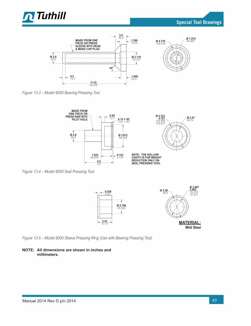
43
13
Special Tool Drawings
Manual 2014 Rev D p/n 2014
MODEL 4500/4600LIP SEAL PRESSING TOOL
MODEL 4500/4600BEARING INSTALLATION TOOL
MODEL 6000BEARING PRESSING TOOL
MODEL 6000SEAL PRESSING TOOL
MODEL 6000SLEEVE PRESSING RING(USE WITH BEARING PRESSING TOOL)
1.025.4
4.0101.6
9.07230.38
.7519.05
Ø 2.9952.994
76.07376.048
Ø 3.5103.500
89.15488.9
Ø 1.5831.578
40.20840.081
Ø 1.5101.505
38.35438.227
Ø 2.31358.750
Ø 2.050.8
Ø 2.17055.118
Ø 3.87298.349
Ø 2.19055.626
Ø 2.050.8
Ø 4.7234.721
119.964119.913
Ø 3.0073.00576.37876.327
Ø 3.4788.14
Ø 3.5088.9
Ø 4.710119.634
Ø 1.57540.005MAKE FROM ONE
PIECE OR PRESS SLEEVE INTO HEAD & MAKE CAP PLUG
MAKE FROMONE PIECE OR
PRESS BAR INTO PILOT HOLE
NOTE: THE HOLLOW CAVITY IS FOR WEIGHT REDUCTION ONLY ON SEAL PRESSING TOOL
NOTE:All dimensions are shown in Inches and millimeters.
MATERIAL:Mild Steel
0.65616.662
9.75247.65
0.512.7
11.53292.86
1.00025.4
0.15 × 30°3.81 × 30°
0.5012.7
1.92348.844
0.1233.124
5.0127
0.2506.35
2.2557.15
1.30033.02
2.050.8
45°
Ø 2.563.5
Ø 3.5403.539
89.91689.891
.130
.1283.3023.251
Figure 13-3 – Model 6000 Bearing Pressing Tool
MODEL 4500/4600LIP SEAL PRESSING TOOL
MODEL 4500/4600BEARING INSTALLATION TOOL
MODEL 6000BEARING PRESSING TOOL
MODEL 6000SEAL PRESSING TOOL
MODEL 6000SLEEVE PRESSING RING(USE WITH BEARING PRESSING TOOL)
1.025.4
4.0101.6
9.07230.38
.7519.05
Ø 2.9952.994
76.07376.048
Ø 3.5103.500
89.15488.9
Ø 1.5831.578
40.20840.081
Ø 1.5101.505
38.35438.227
Ø 2.31358.750
Ø 2.050.8
Ø 2.17055.118
Ø 3.87298.349
Ø 2.19055.626
Ø 2.050.8
Ø 4.7234.721
119.964119.913
Ø 3.0073.00576.37876.327
Ø 3.4788.14
Ø 3.5088.9
Ø 4.710119.634
Ø 1.57540.005MAKE FROM ONE
PIECE OR PRESS SLEEVE INTO HEAD & MAKE CAP PLUG
MAKE FROMONE PIECE OR
PRESS BAR INTO PILOT HOLE
NOTE: THE HOLLOW CAVITY IS FOR WEIGHT REDUCTION ONLY ON SEAL PRESSING TOOL
NOTE:All dimensions are shown in Inches and millimeters.
MATERIAL:Mild Steel
0.65616.662
9.75247.65
0.512.7
11.53292.86
1.00025.4
0.15 × 30°3.81 × 30°
0.5012.7
1.92348.844
0.1233.124
5.0127
0.2506.35
2.2557.15
1.30033.02
2.050.8
45°
Ø 2.563.5
Ø 3.5403.539
89.91689.891
.130
.1283.3023.251
Figure 13-4 – Model 6000 Seal Pressing Tool
MODEL 4500/4600LIP SEAL PRESSING TOOL
MODEL 4500/4600BEARING INSTALLATION TOOL
MODEL 6000BEARING PRESSING TOOL
MODEL 6000SEAL PRESSING TOOL
MODEL 6000SLEEVE PRESSING RING(USE WITH BEARING PRESSING TOOL)
1.025.4
4.0101.6
9.07230.38
.7519.05
Ø 2.9952.994
76.07376.048
Ø 3.5103.500
89.15488.9
Ø 1.5831.578
40.20840.081
Ø 1.5101.505
38.35438.227
Ø 2.31358.750
Ø 2.050.8
Ø 2.17055.118
Ø 3.87298.349
Ø 2.19055.626
Ø 2.050.8
Ø 4.7234.721
119.964119.913
Ø 3.0073.00576.37876.327
Ø 3.4788.14
Ø 3.5088.9
Ø 4.710119.634
Ø 1.57540.005MAKE FROM ONE
PIECE OR PRESS SLEEVE INTO HEAD & MAKE CAP PLUG
MAKE FROMONE PIECE OR
PRESS BAR INTO PILOT HOLE
NOTE: THE HOLLOW CAVITY IS FOR WEIGHT REDUCTION ONLY ON SEAL PRESSING TOOL
NOTE:All dimensions are shown in Inches and millimeters.
MATERIAL:Mild Steel
0.65616.662
9.75247.65
0.512.7
11.53292.86
1.00025.4
0.15 × 30°3.81 × 30°
0.5012.7
1.92348.844
0.1233.124
5.0127
0.2506.35
2.2557.15
1.30033.02
2.050.8
45°
Ø 2.563.5
Ø 3.5403.539
89.91689.891
.130
.1283.3023.251
Figure 13-5 – Model 6000 Sleeve Pressing Ring (Use with Bearing Pressing Tool)
OTE: N All dimensions are shown in inches and millimeters.

44
Parts List
Manual 2014 Rev D p/n 2014
PARTS LISTParts List for Equalizer DF Model 4500 Series Blowers
ITEM NO. PART DESCRIPTION QTY
1 Rotor, Drive 12 Rotor, Driven 13 Housing 14 End Plate 26 End Cover, DE 17 End Cover, BE 18 Gear Assembly 19 Bearing, Dbl Row Ball 2
10 Bearing, Cylindrical Roller 212 Lip Seal 413 Lip Seal 114 Retainer Plate 220 Oil Slinger 120 Oil Slinger 122 Dowel Pin 423 Key, Drive Shaft 124 Key, Gear 225 Washer 226 Cap Screw 2827 Washer 129 Cap Screw 231 Magnetic Drain Plug 237 Breather 239 Port Gasket 242 Nameplate 158 Seal Ring 462 Cap Screw 1468 Spring Pin 170 Oil Gauge 280 Washer 490 Set Screw 2
123 Bearing Spacer 2126 Roll Pin 4174 Pipe Plug 4239 Sleeve 4
ITEM NO. PART DESCRIPTION QTY
304 Mounting Foot 2307 Cap Screw 5
NOTES:
• QUANTITIES SHOWN ARE MAXIMUM VALUES. QUANTITIES MAY VARY BETWEEN BLOWER.
PARTS KITS ARE AVAILABLE. CONSULT AUTHORIZED REPRESENTATIVE FOR PART NUMBERS.

45
Parts List
Manual 2014 Rev D p/n 2014
Parts List for Equalizer RM Model 4600 Series Blowers
ITEM NO. PART DESCRIPTION QTY
1 Rotor, Drive 12 Rotor, Driven 13 Housing 14 End Plate 26 End Cover, DE 17 End Cover, BE 18 Gear Assembly 19 Bearing, Dbl Row Ball 2
10 Bearing, Cylindrical Roller 112 Lip Seal 413 Lip Seal 114 Retainer Plate 420 Oil Slinger 120 Slinger 122 Dowel Pin 423 Key, Drive Shaft 124 Key, Gear 225 Washer 226 Cap Screw 2827 Washer 129 Cap Screw 231 Magnetic Drain Plug 237 Breather 242 Nameplate 150 Roller Bearing 158 Seal Ring 462 Cap Screw 1668 Roll Pin 170 Oil Gauge 280 Washer 890 Set Screw 2
123 Bearing Spacer 4126 Roll Pin 4174 Pipe Plug 4239 Sleeve 4281 Spacer 3
ITEM NO. PART DESCRIPTION QTY
282 Spring 3304 Mounting Foot 2307 Cap Screw 9
NOTES:
• QUANTITIES SHOWN ARE MAXIMUM VALUES. QUANTITIES MAY VARY BETWEEN BLOWER.
PARTS KITS ARE AVAILABLE. CONSULT AUTHORIZED REPRESENTATIVE FOR PART NUMBERS.

46
Parts List
Manual 2014 Rev D p/n 2014
Parts List for Equalizer RM Model 6000 Series Blowers
ITEM NO. PART DESCRIPTION QTY
1 Rotor, Drive 12 Rotor, Driven 13 Housing 14 End Plate 26 End Cover, DE 17 End Cover, BE 18 Gear Assembly 19 Ball Bearing 2
10 Roller Bearing 212 Lip Seal 413 Lip Seal 114 Retainer Plate 420 Slinger 122 Dowel Pin 423 Key, Drive Shaft 124 Key, Gear 225 Washer 226 Cap Screw 3229 Cap Screw 330 Cap Screw 231 Magnetic Drain Plug 237 Breather 242 Nameplate 158 Seal Ring 462 Cap Screw 1668 Roll Pin 170 Oil Gauge 280 Washer 10117 Washer 2123 Bearing Spacer 2126 Roll Pin 4174 Pipe Plug 2195 Lift Lug 2239 Sleeve 4281 Spacer 2282 Spring 4304 Mounting Foot 2
ITEM NO. PART DESCRIPTION QTY
304 Mounting Foot 2307 Cap Screw 10
NOTES:
• QUANTITIES SHOWN ARE MAXIMUM VALUES. QUANTITIES MAY VARY BETWEEN BLOWER.
PARTS KITS ARE AVAILABLE. CONSULT AUTHORIZED REPRESENTATIVE FOR PART NUMBERS.

47
Assembly Drawings
Manual 2014 Rev D p/n 2014
ASSEMBLY DRAWINGSCutaway Drawings for Models 4504, 4506, 4509, and 4512

48
Assembly Drawings
Manual 2014 Rev D p/n 2014
Cutaway Drawings for Models 4604, 4606, 4609, and 4612
37
4138 39
174
40 80 307 31304
70
174
30480 307 31
70
37
39
174
80 307
4140 38
30431
70
37
174
3180 307 304
70
37
241412 9239 581282 2250126
13
62 1028126 282 3 2
68
307
27
20
USE SEALANT6
23
4
16
8
7USE
SEALANT
25
29
SHIM PACK
DOWEL PINS
CAP SCREW
SCREWLOCKPLATE
TIMINGGEARHUB
TIMING GEARASSEMBLY (ITEM 8)
SHIM INCLUDED
IN ITEM 8GEAR ASSY
VERTICAL FLOWLEFT DRIVE SHOWN
HORIZONTAL FLOWTOP DRIVE ONLY

49
Assembly Drawings
Manual 2014 Rev D p/n 2014
Cutaway Drawings for Models 6012, 6016, and 6024
USEUSESEALANTSEALANT
SHIMSHIMINCLUDED ININCLUDED IN
ITEM 8ITEM 8GEAR ASSYGEAR ASSY
304 31
70
37
174
30780
195
31
37
304
70
174
80 307
195
13
23
6
20
USE SEALANT
68
29
29
25
8
7
16
9 1412239 58 241123126 22
28162 26 282 10 3 2 4
SHIM PACK
DOWEL PINS
CAP SCREW
SCREWLOCKPLATE
TIMINGGEARHUB
TIMING GEARASSEMBLY (ITEM 8)
HORIZONTAL FLOWTOP DRIVE ONLY
VERTICAL FLOW

WARRANTY – BLOWER PRODUCTSSubject to the terms and conditions hereinafter set forth and set forth in General Terms of Sale, Tuthill Springfield (the Seller) warrants products and parts of its manufacture, when shipped, and its work (including installation and start-up) when performed, will be of good quality and will be free from defects in material and workmanship. This warranty applies only to Seller’s equipment, under use and service in accordance with seller’s written instructions, recommendations and ratings for installation, operating, maintenance and service of products, for a period as stated in the table below. Because of varying conditions of installation and operation, all guarantees of performance are subject to plus or minus 5% variation. (Non-standard materials are subject to a plus or minus 10% variation)
PRODUCTTYPE
TYPE OF APPLICATION
ATMOSPHERIC AIR OR PROCESS AIR WITHOUT LIQUIDS PRESENT
PROCESS GASES OTHER THAN AIR, OR ANY LIQUID INJECTED APPLICATION
New(Qx™ models only)
30 months from date of shipment, or 24 months after initial startup date, whichever occurs first. Consult Factory
New(all other models)
24 months from date of shipment, or 18 months after initial startup date, whichever occurs first
18 months from date of shipment, or 12 months after initial startup date, whichever occurs first
Repair 12 months from date of shipment, or remaining warranty period, whichever is greater
12 months from date of shipment, or remaining warranty period, whichever is greater
THIS WARRANTY EXTENDS ONLY TO BUYER AND/OR ORIGINAL END USER, AND IN NO EVENT SHALL THE SELLER BE LIABLE FOR PROPERTY DAMAGE SUSTAINED BY A PERSON DESIGNATED BY THE LAW OF ANY JURISDICTION AS A THIRD PARTY BENEFICIARY OF THIS WARRANTY OR ANY OTHER WARRANTY HELD TO SURVIVE SELLER’S DISCLAIMER.
All accessories furnished by Seller but manufactured by others bear only that manufacturer’s standard warranty.
All claims for defective products, parts, or work under this warranty must be made in writing immediately upon discovery and, in any event within one (1) year from date of shipment of the applicable item and all claims for defective work must be made in writing immediately upon discovery and in any event within one (1) year from date of completion thereof by Seller. Unless done with prior written consent of Seller, any repairs, alterations or disassembly of Seller’s equipment shall void warranty. Installation and transportation costs are not included and defective items must be held for Seller’s inspection and returned to Seller’s Ex-works point upon request.
THERE ARE NO WARRANTIES, EXPRESSED, IMPLIED OR STATUTORY WHICH EXTEND BEYOND THE DESCRIPTION ON THE FACE HEREOF, INCLUDING WITHOUT LIMITATION, THE IMPLIED WARRANTIES OF MERCHANTABILITY AND FITNESS OF PURPOSE.
After Buyer’s submission of a claim as provided above and its approval, Seller shall at its option either repair or replace its product, part, or work at the original Ex-works point of shipment, or refund an equitable portion of the purchase price.
The products and parts sold hereunder are not warranted for operation with erosive or corrosive material or those which may lead to build up of material within the product supplied, nor those which are incompatible with the materials of construction. The Buyer shall have no claim whatsoever and no product or part shall be deemed to be defective by reason of failure to resist erosive or corrosive action nor for problems resulting from build-up of material within the unit nor for problems due to incompatibility with the materials of construction.
Any improper use, operation beyond capacity, substitution of parts not approved by Seller, or any alteration or repair by others in such manner as in Seller’s judgment affects the product materially and adversely shall void this warranty.
No employee or representative of Seller other than an Officer of the Company is authorized to change this warranty in any way or grant any other warranty. Any such change by an Officer of the Company must be in writing.
The foregoing is Seller’s only obligation and Buyer’s only remedy for breach of warranty, and except for gross negligence, willful misconduct and remedies permitted under the General Terms of Sale in the sections on CONTRACT PERFORMANCE, INSPECTION AND ACCEPTANCE and the PATENTS Clause hereof, the foregoing is BUYER’S ONLY REMEDY HEREUNDER BY WAY OF BREACH OF CONTRACT, TORT OR OTHERWISE, WITHOUT REGARD TO WHETHER ANY DEFECT WAS DISCOVERED OR LATENT AT THE TIME OF DELIVERY OF THE PRODUCT OR WORK. In no event shall Buyer be entitled to incidental or consequential damages. Any action for breach of this agreement must commence within one (1) year after the cause of action has occurred.
May 2008

IMPORTANTAll blowers manufactured by Tuthill Springfield are date coded at time of shipment. In order to assure you of the full benefits of the product warranty, please complete, tear out and return the product registration card, or register online at tuthillvacuumblower.com.
OPERATING DATA FORM / PRODUCT REGISTRATIONIt is to the user’s advantage to have the requested data filled in below and available in the event a problem should develop in the blower or the system. This information is also helpful when ordering spare parts.
Model No. V-Belt Size Length
Serial No. Type of Lubrication
Startup Date
Pump RPM Operating Vacuum
Pump SheaveDiameter Any other Special Accessories Supplied or in use:
Motor SheaveDiameter
Motor RPM HP
NOTES:

Tuthill Springfield4840 West Kearney StreetSpringfield, Missouri USA 65803-8702O 417.865.8715 800.825.6937 F 417.865.2950tuthillvacuumblower.com
For Service & Repair, TechnicalSupport, or Product Sales contact:
Copyright © 2020 Tuthill Springfield All rights reserved. Product information and specifications subject to change.
INTERNATIONAL QUALITY STANDARD
REGISTERED
VACUUM & BLOWER SYSTEMS
TUTHILL CORPORATION
Manual 2014 Rev D p/n 201401/20