Embed Size (px)
Citation preview
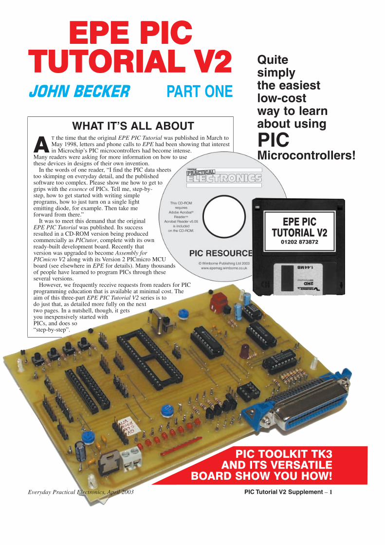
EEPPEE PPIICCTTUUTTOORRIIAALL VV22
WHAT IT’S ALL ABOUT
A T the time that the original EPE PIC Tutorial was published in March toMay 1998, letters and phone calls to EPE had been showing that interestin Microchip’s PIC microcontrollers had become intense.
Many readers were asking for more information on how to usethese devices in designs of their own invention.
In the words of one reader, “I find the PIC data sheetstoo skimping on everyday detail, and the publishedsoftware too complex. Please show me how to get togrips with the essence of PICs. Tell me, step-by-step, how to get started with writing simpleprograms, how to just turn on a single lightemitting diode, for example. Then take meforward from there.”
It was to meet this demand that the originalEPE PIC Tutorial was published. Its successresulted in a CD-ROM version being producedcommercially as PICtutor, complete with its ownready-built development board. Recently thatversion was upgraded to become Assembly forPICmicro V2 along with its Version 2 PICmicro MCUboard (see elsewhere in EPE for details). Many thousandsof people have learned to program PICs through theseseveral versions.
However, we frequently receive requests from readers for PICprogramming education that is available at minimal cost. Theaim of this three-part EPE PIC Tutorial V2 series is todo just that, as detailed more fully on the nexttwo pages. In a nutshell, though, it getsyou inexpensively started withPICs, and does so“step-by-step”.
��������� PART ONE
Everyday Practical Electronics, April 2003 PIC Tutorial V2 Supplement – 1
PIC TOOLKIT TK3AND ITS VERSATILE
BOARD SHOW YOU HOW!
Quitesimplythe easiestlow-costway to learnabout using
PICMicrocontrollers!
EPE PICTUTORIAL V2
01202 873872
��� ���� ���
Over five years on from the publicationof the original EPE PIC Tutorial, a numberof things have changed, yet at the sametime the basics of programming PICmicrocontrollers have not.
This revision is thus a mixture of the oldand the new. The old aspect is that the com-mands used to program PICs remain thesame. The new aspects, though, are several:
The original EPE PIC Tutorial illustrat-ed its example programs in a programmingdialect known as TASM. This dialect isusable with a variety of tables whose con-tents can be modified to suit many types ofmicrocontroller and microprocessor. It hadbeen modified to suit PICs by readerDarren Crome.
This revision now has its programmingexamples written in Microchip’s own PICprogramming dialect, MPASM. This dialectis the “industry standard” and thus has farwider appeal than TASM, although the basicdifferences between the two are slight.
Secondly, the original EPE PIC Tutorialconcentrated on the now-obsoletePIC16C84 as being the target device. Thismicrocontroller effectively became replacedin 1997 by the pin-for-pin compatiblePIC16F84, which is an equally excellentdevice to use to illustrate PIC programmingtechniques. More recently the PIC16F84Ahas arrived on the scene. The PIC16F84 andPIC16F84A (two of the devices in thePIC16F8x family) can be used interchange-ably in this EPE PIC Tutorial V2 (referredto from now on as the Tutorial).
������������ Once you know how to program a
PIC16F84 you are well equipped to writeprograms for other PICs, although there aresome minor differences in the way that thevarious PIC families handle some of thesame functions.
Apart from the PIC16F8x family, twoother PIC families are eminently suited tohobbyist constructors, notably thePIC16F87x and PIC16F62x families(although they are not immediately suitedto this Tutorial). However, in the final partof this three part series, basic differencesbetween the way that the PIC16F8x,PIC16F87x and PIC16F62x families do thesame thing are highlighted and the Tutorialprograms can be readily modified to run onthese devices. Examples of some usefulroutines specific to the PIC16F87x familyare included.
It is stressed, though that this Tutorialdoes not attempt to be a full tutorial onevery aspect of the three families. Nor doesit examine specific aspects of some otherPIC families whose functions are moreadvanced than most readers probablyrequire.
Also, the Tutorial does not teach the useof Microchip’s MPASM and MPLAB pro-gramming software, and it does not coverany PIC variant or dialect that is pro-grammed in versions of BASIC.
An important aspect of this revision isthat it has been designed for use with theEPE PIC Toolkit TK3 printed circuit boardand software (published Oct/Nov 2001),both of which, plus their two texts, youneed in order to get full benefit from thisTutorial. See the Resources panel fordetails of obtaining them. Note that these
are included on the EPE PIC ResourcesCD-ROM. From hereon the software andp.c.b. are jointly referred to simply as TK3.
It should be noted that TK3 was writtento run under Windows 95, 98 and ME. Torun it under Windows NT, XP and 2000 thesoftware must be used as described inMark Jones’ article Using TK3 withWindows XP and 2000 of Oct ’02. Thisarticle is also carried on the EPE PICResources CD-ROM.
In keeping with the original Tutorial, weassume in this series that you have no pre-vious knowledge of PICs and their pro-gramming. We thus start as we did before,by explaining the basic nature of a PICmicrocontroller.
������ �������A PIC chip, in this context, is a micro-
controller integrated circuit manufacturedby Microchip. When asked about the name’sorigin, Microchip’s Technical Department
2 – PIC Tutorial V2 Supplement Everyday Practical Electronics, April 2003
� ����
A special composite EPE PICResources CD-ROM has been producedto accompany this series. It includes theTutorial software for the entire series,EPE Toolkit TK3 software, completereproductions of the TK3 texts ofOct/Nov ’01, Using TK3 with WindowsXP and 2000 (Oct ’02) and a broad selec-tion of PIC-related articles published inEPE over the last several years andwhich illustrate practical examples ofvarious advanced programming func-tions and techniques. Some unpublishedarticles are included as well. The full listis given elsewhere in EPE.
Alternatively, software for TK3 andthis Tutorial can be downloaded free fromthe EPE FTP Site. Disks for both sets ofsoftware (CD-ROM for TK3, and 3.5indisk for this Tutorial) are also available
from the EPE Editorial Office. Backissues (or photocopies) or Back IssueCD-ROMs of published texts can also bepurchased (see the Back Issues page).
The EPE FTP Site is most easilyaccessed via the main page atwww.epemag.wimborne.co.uk. Clickon the FTP Site (Downloads) option atthe top, then click down the pathspub/PICS then select PIC Tutorial V2 orToolkit TK3.
The printed circuit board for TK3 isavailable from the EPE PCB Service,code 319. Note, you will require therelevant back issues or the EPE PICResources CD-ROM to be able too buildthis.
See the EPE PCB Service page for theprice and ordering details of the disksand p.c.b.
RA2
RA3
RA4/TOCKI
MCLR
GND
RB0/INT
RB1
RB2
RB3 RB4
RB5
RB6
RB7
+VE
OSC2/CLK OUT
OSC1/CLK IN
RA0
RA11
2
3
4
5
6
7
8
9 10
11
12
13
14
15
16
17
18
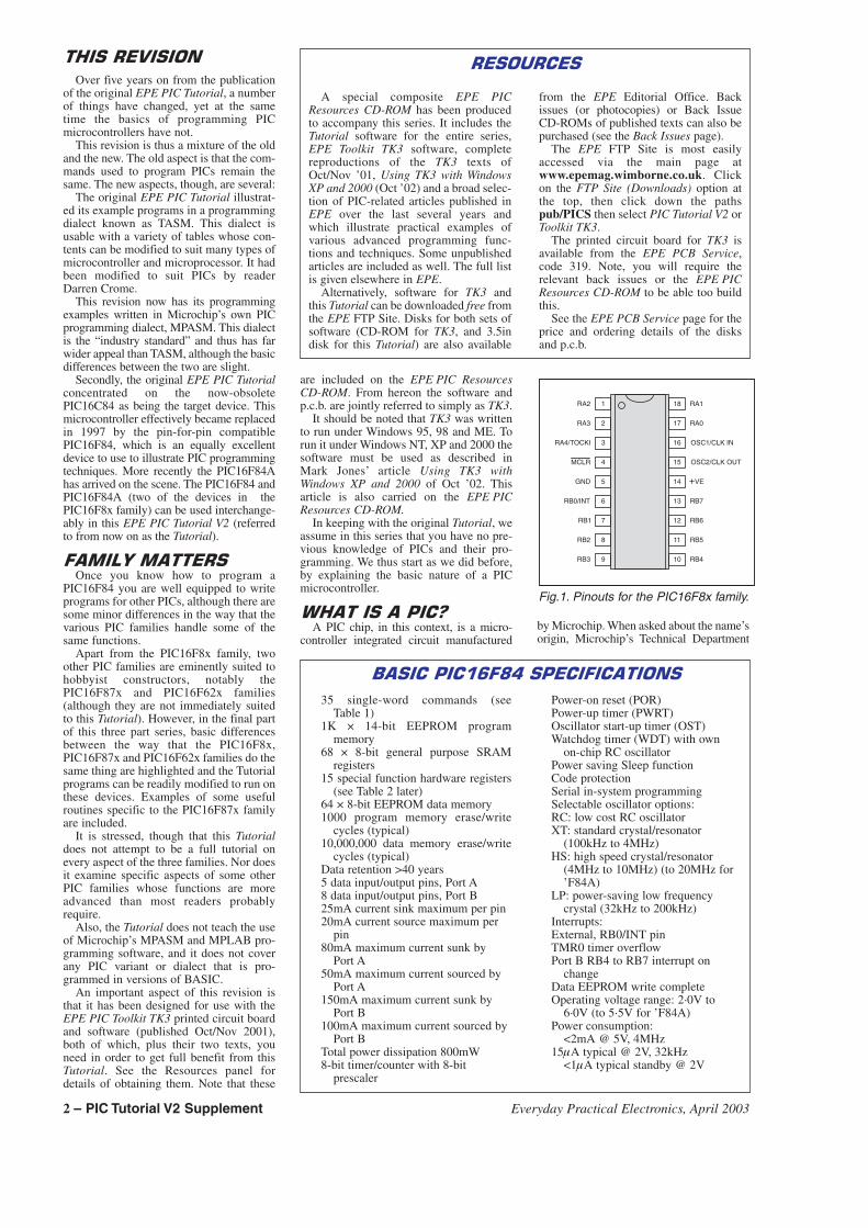
Fig.1. Pinouts for the PIC16F8x family.
�� ������������ ������������
35 single-word commands (seeTable 1)
1K × 14-bit EEPROM programmemory
68 × 8-bit general purpose SRAMregisters
15 special function hardware registers(see Table 2 later)
64 × 8-bit EEPROM data memory1000 program memory erase/write
cycles (typical)10,000,000 data memory erase/write
cycles (typical)Data retention >40 years5 data input/output pins, Port A8 data input/output pins, Port B25mA current sink maximum per pin20mA current source maximum per
pin80mA maximum current sunk by
Port A50mA maximum current sourced by
Port A150mA maximum current sunk by
Port B100mA maximum current sourced by
Port BTotal power dissipation 800mW8-bit timer/counter with 8-bit
prescaler
Power-on reset (POR)Power-up timer (PWRT)Oscillator start-up timer (OST)Watchdog timer (WDT) with own
on-chip RC oscillatorPower saving Sleep functionCode protectionSerial in-system programmingSelectable oscillator options:RC: low cost RC oscillatorXT: standard crystal/resonator
(100kHz to 4MHz)HS: high speed crystal/resonator
(4MHz to 10MHz) (to 20MHz for’F84A)
LP: power-saving low frequencycrystal (32kHz to 200kHz)
Interrupts:External, RB0/INT pinTMR0 timer overflowPort B RB4 to RB7 interrupt on
changeData EEPROM write completeOperating voltage range: 2·0V to
6·0V (to 5·5V for ’F84A)Power consumption:
<2mA @ 5V, 4MHz15�A typical @ 2V, 32kHz
<1�A typical standby @ 2V
TUTORIAL 1:Minimum commands neededPort default valuesInstruction ORGInstruction ENDCommand GOTOProgram TK3TUT1.ASM
TUTORIAL 2:Clock cyclesFile registersBitsBytesSetClearCommand CLRFCommand CLRWCommand BSFCommand BCFPorts and Port directionsRegister STATUSSTATUS register bit 5Banks 0 and 1Program TK3TUT2.ASM
TUTORIAL 3:Names in place of numbersCase sensitivityLabelsRepetitive loopInstruction EQUProgram TK3TUT3.ASM
TUTORIAL 4:Command MOVLWCommand MOVWFCommand RLFCommand RRFCommand BTFSSCommand BTFSCInstruction #DEFINEInstruction BANK0Instruction BANK1Register PORTARegister TRISARegister PORTBRegister TRISBRegister PCLNaming numbersBit namingProgram counterSTATUS register bit 0Carry flagBit codes C, F, WBit testingConditional loopPin protectionProgram TK3TUT4.ASMProgram TK3TUT5.ASM
TUTORIAL 5:STATUS bit 2Zero flagBit code ZCommand MOVFProgram TK3TUT6.ASM
TUTORIAL 6:Command INCFCommand DECFCommand INCFSZCommand DECFSZCounting upwards(incrementing)Counting downwards(decrementing)Use of a file as a counterProgram TK3TUT7.ASM
TUTORIAL 7:Switch monitoringCommand ANDLWCommand ANDWFCommand ADDWFCommand ADDLWNibblesSTATUS bit 1Digit Carry flagBit code DCProgram TK3TUT8.ASM
TUTORIAL 8:Increasing speed ofTK3TUT8Bit testing for switch statusProgram TK3TUT9.ASM
TUTORIAL 9:Responding to a switch pressonly at the moment ofpressingProgram TK3TUT10.ASM
TUTORIAL 10:Performing functionsdependent upon which switchis pressedUse of a common routineserving two functionsProgram TK3TUT11.ASM
TUTORIAL 11:Reflecting PORTA’s switcheson PORTB’s l.e.d.sCommand COMFCommand SWAPFInverting a byte’s bit logicSwapping a byte’s nibblesProgram TK3TUT12.ASMProgram TK3TUT13.ASMProgram TK3TUT14.ASM
TUTORIAL 12:Generating an outputfrequency in response to aswitch pressThe use of two port bits setto different input/outputmodesCommand NOPProgram TK3TUT15.ASM
TUTORIAL 13:Command CALLCommand RETURNCommand RETLWProgram TK3TUT16.ASM
TUTORIAL 14:TablesRegister PCL (again)Register PCLATHProgram TK3TUT17.ASM
TUTORIAL 15:Using four switches to createfour different notesUse of a table to selectivelyroute program flowProgram TK3TUT18.ASM
TUTORIAL 16:Indirect addressingUsing unnamed filelocationsRegister FSRRegister INDFProgram TK3TUT19.ASM
TUTORIAL 17:Tone modulationCommand XORLWCommand XORWFCommand IORLWCommand IORWFProgram TK3TUT20.ASMProgram TK3TUT21.ASMProgram TK3TUT22.ASM
TUTORIAL 18:Register OPTIONRegister INTCONRegister TMR0Use of internal timerProgram TK3TUT23.ASM
TUTORIAL 19:BCD (Binary CodedDecimal) countingProgram TK3TUT24.ASM
TUTORIAL 20:Real-time timing at 1/25thsecondCounting seconds 0 to 60Program TK3TUT25.ASM
TUTORIAL 21:Using 7-segment l.e.d.displaysShowing hours, minutes andsecondsCommand IORLW (usage)Program TK3TUT26.ASMProgram TK3TUT27.ASMProgram TK3TUT28.ASM
TUTORIAL 22:Using intelligent l.c.d.sSetting l.c.d. contrastInitialising the l.c.d.Sending a message to thel.c.d.Program TK3TUT29.ASM
TUTORIAL 23:Coding hours, minutes andseconds for an l.c.d.Shortened clock monitoringcodeCommand SUBLWCommand SUBWFProgram TK3TUT30.ASM
TUTORIAL 24:Adding time-setting switchesProgram TK3TUT31.ASM
TUTORIAL 25:Writing and readingEEPROM file dataRegister EECON1Register EECON2Register EEDATARegister EEADRProgram TK3TUT32.ASM
TUTORIAL 26:Illustrating use of EEPROMdata read/writeConverting binary value tohexadecimalProgram TK3TUT33.ASM
TUTORIAL 27:InterruptsCommand RETFIEProgram TK3TUT34.ASMProgram TK3TUT35.ASM
TUTORIAL 28:Command SLEEPProgram TK3TUT36.ASM
TUTORIAL 29:Watchdog timer (WDT)Command CLRWDTProgram TK3TUT37.ASM
TUTORIAL 30:Misc Special Register bits
TUTORIAL 31:INCLUDE files commandEmbedded configuration dataEmbedded Data EEPROM valuesEmbedded PIC type dataEmbedded RadixProgram TK3TUT38.ASM
TUTORIAL 32:PIC16F8x, PIC16F87x,PIC16F62x family codingdifferencesPIC16F87x PORTAPIC16F87x Data EEPROM usePIC16F62x PORTAPIC16F62x Data EEPROM useProgram TK3TUT39.ASMProgram TK3TUT40.ASM
TUTORIAL 33:Converting binary values todecimalProgram TK3TUT41.ASM
TUTORIAL 34:Multiplication routineProgram TK3TUT42.ASM
TUTORIAL 35:Division routineProgram TK3TUT43.ASM
TUTORIAL 36:ADC conversion routine forPIC16F87x familyProgram TK3TUT44.ASM
TUTORIAL 37:CBLOCK commandInterfacing to external serialEEPROM chips, for PIC16F87xfamilyProgram TK3TUT45.ASM
TUTORIAL 38:Outputting serial data at aspecified BAUD rate, forPIC16F87x familyProgram TK3TUT46.ASM
TUTORIAL 39:Practical example recordinganalogue data to serialEEPROM and subsequentoutputting as RS-232 serial dataProgram TK3TUT47.ASM
TUTORIAL 40:ProgrammingPICs vs. hardwareSumming-up
APPENDIX A:Bugged Teaser!
APPENDIX B:Useful PIC informationFurther reading
TUTORIAL CONCEPTS EXAMINED
Everyday Practical Electronics, April 2003 PIC Tutorial V2 Supplement – 3
replied, “PIC is not an acronym; it is just atrademarked name that GeneralInstruments came up with a long time ago”.(GI were the originators of PICs.)
A microcontroller is similar to a micro-processor but it additionally contains itsown program command code memory, datastorage memory, bi-directional (input/out-put) ports and a clock oscillator. Manymicroprocessors require the use of addi-tional chips to provide these requirements;microcontrollers are totally self-contained.
The great advantage of microcontrollers isthat they can be programmed to performmany functions for which many other chipswould normally be required. This not onlymakes for simplicity in electronic designs,but also allows some functions to be per-formed which could not be done using nor-mal digital logic chips – i.e. circuits forwhich, previously, a microprocessor andperipheral devices would have been required.
PICs are manufactured and supplied“empty”. That is, they are without programcodes (commands) and cannot control acircuit until they have been provided with aprogram that tells them what to do. It is thetask of the program writer (you) to tellthem what that is.
The commands are written in a spe-cialised form of English, largely consistingof mnemonics, known as the “sourcecode”. An assembly program (such as TK3)then translates (assembles) the source codecommands into a numerical form that thePIC can understand, the “program code”.This code, which is normally in hexadeci-mal, is then sent (loaded) in binary formatto the PIC by electronic hardware, such asTK3’s p.c.b.
����������� There are many families of PIC micro-
controller available, ranging from thosewhich can only be programmed once, tothose that can be repeatedly repro-grammed. The former are typically knownas One Time Programmable (OTP)devices, and because of this characteristicare not well-suited to hobbyist use sincethey cannot have their software codechanged once they have been programmed.
There are two basic families of repro-grammable PICs: those that require anultra-violet light unit to erase their previousdata before being reprogrammed, butwhich are now essentially obsolete, andthose which are electrically erasable.
In the latter category fall the three devicefamilies already mentioned, of which it isthe PIC16F84 device we use here. It hasbeen chosen because of its ease of repro-gramming and because it does not haveadditional features that can prove difficultto understand for beginners. Its pinouts areshown in Fig.1, and its basic attributesgiven in the Specifications panel.
It is an EEPROM (electrically erasableprogrammable read only memory) device,also known as a “Flash” device, hence the“F” infix in its type number. This meansthat it can be rapidly reprogrammed asoften as you wish, without the need forultra-violet erasing.
����� ��� Note that there are several sub-versions
of individual PIC types, having suffixessuch as -04, -10 and -20. The suffix indi-cates the maximum clock rate at which the
chip can be used: 4MHz, 10MHz and20MHz respectively. You may use anydevice speed rating for this Tutorial,although the -04 is likely to be stocked bymore component suppliers.
The PIC16F84 used here has twoinput/output (I/O) ports, Port A and Port B.Port A has five pins (RA0 to RA4), andPort B has eight pins (RB0 to RB7). Weshall be using the PIC in two of its fouroscillator modes, RC (resistor/capacitor)and XT (standard crystal up to 4MHz), theformer being variable, the latter using a3·2768MHz crystal.
To re-emphasise an earlier point, muchof the information about the commandswhich we present here is, in mostinstances, applicable to other members ofthe PIC family. Once you understand aPIC16F84 you should have no difficultyapplying your knowledge to other PICs.
�������������There are six things that you need in
order to program a PIC:
� PC-compatible computer having a stan-dard (Centronics-compatible) parallelprinter port (USB ports are not suitable)
� purpose built programming hardwareboard (e.g. TK3)
� standard (Centronics) parallel printerport connecting cable
� suitable power supply (TK3 runs from9V d.c., which can be supplied via aplug-in mains adaptor)
� word-processing program (text editor)
� assembly and send (download) softwareprogram (e.g. TK3)
It is worth noting that this Tutorial andthe TK3 software can be used withMagenta’s version of the TK3 board, andwith the commercial Version 2 PICmicroMCU Development Board. However, thesetwo boards do not have the numbered CPconnection points referred to in this textregarding the EPE TK3 board, but they dohave pin function notations and the con-nections should be obvious.
Data is output from the computer to thePIC via the parallel printer port (addresses378h, 278h and 3BCh are supported byTK3). It is output serially, data on port lineD0, and a clock signal on line D1.Additional computer printer port lines areused by TK3 to enable such functions asreading back program code from a PIC.
You must be able to use a word-process-ing program. This must produce a text filethat is totally without formatting and printercommands. That is, it must be able to gen-erate a pure ASCII text file (and to inputone). It is stressed that the source code(.ASM) files must be in pure ASCII textformats without printer or display format
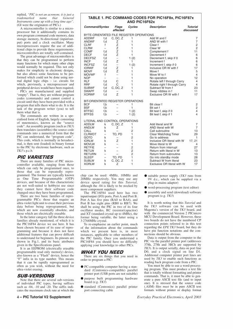
TABLE 1. PIC COMMAND CODES FOR PIC16F8x, PIC16F87xAND PIC16F62x
Command/Syntax Flags Cycles Description Tutorialaffected discussed
BYTE-ORIENTATED FILE REGISTER OPERATIONSADDWF f,d C, DC, Z 1 Add W and f 7ANDWF f,d Z 1 AND W with f 7CLRF f Z 1 Clear f 2CLRW – Z 1 Clear W 2COMF f,d Z 1 Complement f 11DECF f,d Z 1 Decrement f 6DECFSZ f,d – 1 (2) Decrement f, skip if 0 6INCF f,d Z 1 Increment f 6INCFSZ f,d – 1 (2) Increment f, skip if 0 6IORWF f,d Z 1 Inclusive OR W with f 17MOVF f,d Z 1 Move f 5MOVWF f – 1 Move W to f 4NOP – – 1 No operation 12RLF f,d C 1 Rotate left f through Carry 4RRF f,d C 1 Rotate right f through Carry 4SUBWF f,d C, DC, Z 1 Subtract W from f 23SWAPF f,d – 1 Swap nibbles in f 11XORWF f,d Z 1 Exclusive OR W with f 17
BIT-ORIENTATED REGISTER OPERATIONSBCF f,b – 1 Bit clear f 2BSF f,b – 1 Bit set f 2BTFSC f,b – 1 (2) Bit test f, skip if 0 4BTFSS f,b – 1 (2) Bit test f, skip if 1 4
LITERAL AND CONTROL OPERATIONSADDLW k C, DC, Z 1 Add literal and W 7ANDLW k Z 1 AND literal with W 7CALL k – 2 Call subroutine 13CLRWDT – TO, PD 1 Clear Watchdog Timer 29GOTO k – 2 Go to address 1IORLW k Z 1 Inclusive OR literal with W 17, 21MOVLW k – 1 Move literal to W 4RETFIE – – 2 Return from interrupt 27RETLW k – 2 Return with literal in W 13RETURN – – 2 Return from subroutine 13SLEEP – TO, PD 1 Go into standby mode 28SUBLW k C, DC, Z 1 Subtract W from literal 23XORLW k Z 1 Exclusive OR literal with W 17
4 – PIC Tutorial V2 Supplement Everyday Practical Electronics, April 2003
commands embedded in them. (TK3 offers achoice of editors, including DOS Edit,Windows Notepad and Windows Wordpad.)
�������������������
To use this Tutorial with the basic TK3p.c.b. you need the following additionalcomponents:
330� resistor, 0·25W 5% carbon film (8off)
1�F capacitor, axial elect. 10V2-line, 16-characters per line alphanu-
meric liquid crystal display module anddatasheet
Optional: 4-digit multiplexed commoncathode 7-segment l.e.d. display moduleand datasheet
Personal (high-impedance) headphonesJack socket to suit headphonesExtra push-to-make switch for connec-
tion via flying leadsStranded connecting wireSolder
�����������Throughout this Tutorial we shall exam-
ine in a fair amount of detail the 35 basicPIC commands. It is hoped that this willgive you all the necessary information thatwill enable you to conceive a design inwhich you can use a PIC16F84 to controlwhatever situation you wish, and to writethe code that will let it do so.
There is, though, much more to writingprograms than you may at this momentfully appreciate. Knowledge about individ-ual commands and the way in which theycan be used is not enough in itself.
Programming is a way of looking at theworld that other people may not recognise.You must have the mental ability to seeeach programming situation as a step bystep function, visualising and analysing inyour mind exactly how it is that you needto specify the complete program flow.
You have to write the sequence of eventswith the correct grammar, with the correctspelling and in the correct order.Undoubtedly you will make mistakeswhile you are writing the code, failing tosee the correct sequence of events andusing incorrect command structures.
You require the ability to analyse whatyou have done wrong and to correct it. Youare likely to be confronted with an overalltask that may, on occasion, take you intoseveral days or even weeks of dedicatedconcentration.
Readers have occasionally asked howthey can be taught to think like a program-mer. There is no easy way in which this canbe taught. Some people have the ability,some do not. The best way to learn is byactually writing snippets of code and getthose to work, giving you the experienceand confidence to progress to more com-plex situations. Throughout this Tutorialwe try to encourage you in this approach.
Programming, to those who have the abil-ity to see things “as they are” and not “howthey seem to be”, can become extremelyaddictive. You could find yourself com-pelled to get back to the keyboard and PICprogrammer at any conceivable hour. Youhad better have an understanding family!
�� ������� ��� �To get you started programming PICs
through this Tutorial, you need the TK3
board mentioned earlier plus the few extracomponents just listed. TK3 already haseight light emitting diodes (l.e.d.s), fourpushbutton switches and four uncommitted(open-collector) npn transistors.
These facilities help to illustrate the pro-gram examples discussed in the text andencourage you to build up your experienceof how the PIC16F84 can be made torespond to different practical situations.
In this text, we start at the very begin-ning of programming. The first lesson isabout the very minimum of informationthat needs to be written into a program list-ing before the PIC can do anything else.
We then, “step by step”, take a specificvery simple task, such as turning on anl.e.d., and describe in detail each of thecommands that are required to do the task.
Having described one task, we then takethat idea a stage further, adding a few morecommands that will enhance the capabilitiesof the program. Each of these commands issimilarly discussed in detail. Thus weprogress, taking simple ideas, and illustratinghow they can be achieved and then enhanced.
We feel that this approach is far moreuseful than describing each and every oneof the commands in turn before we ever getto use them. Most people learn by doing,reading about things in short sections andapplying the knowledge in practical bite-sized chunks. A complete chapter on all thecommands in sequence would be too muchto remember and understand in one go.
The complete list of Microchip’s com-mands for the PIC16F8x, PIC16F87x andPIC16F62x families is shown in Table 1. Allare discussed and demonstrated. In the earlyyears of PICs there used to be two others,OPTION and TRIS, but Microchip havedropped them from their recent PIC families.
As you will see, there are a lot of “bit-orientated” sub-commands available aswell as the main commands. Some of theseare similar in operation and close examina-tion will be given only to the principal ones– once you understand these, use of thesimilar bit-setting commands available willbecome obvious.
�������� ������ The Tutorial is split into numbered sec-
tions. Each deals with specific coding top-ics but, in most cases, is a direct follow-onfrom the previous one, and is nearly alwaysvisually illustrated by the displays on theTK3 p.c.b. The exception to the latter iswhen sound is used as the output medium,when the personal headphones are needed.
At the end of most sections there are afew simple exercises which allow you toexperiment with the program presented inthat section. You will only be expected touse the commands that have already beenintroduced to you. None of them should taxyour brain too much, but they will, hope-fully, encourage you to think of alternativeways in which the same basic task can betackled, or to consider other tasks that canbe achieved using similar techniques.
By the end of the complete Tutorial, youwill know how to get the PIC16F84 torespond to switches and other external sig-nal sources, send data to various types ofdisplay, to create sound, to be the heart of a24-hour clock and to store data in its non-volatile EEPROM memory.
Readers who have had experience ofprogramming in BASIC, or with other
types of microprocessor or microcon-troller, will find that once a few commandshave had their functions explained, usingthem will rapidly become instinctive. Theauthor, having many years of such experi-ence, effectively learned about PICs andhow to use them over a single weekend,just by doing a bit of experimenting.
Other readers without such experiencewill, it has to be said, have to becomeaccustomed to understanding program-ming itself as a step by step process. Ananalytical mind is required and, as said ear-lier, there is no easy way in which pro-gramming can be taught to those who lackthis ability.
������������� � Throughout this Tutorial we present var-
ious programming exercises at which to tryyour hand. In most cases, you are request-ed to modify an existing tutorial program.This requires it to be saved, assembled andsent to the PIC.
It is important that when you make thesechanges, you do not save the variant underthe same name as the original. It must havea different name. If you do save under thesame name, the original file will bereplaced by the new one. You can save eachprogram variant by any name of yourchoosing, but use the same .ASM exten-sion as the examples use. You might con-sider using TRY1.ASM, TRY2.ASM, etc.
It is recommended that you save theoriginal file under the new name beforeyou make any changes, to avoid curse-wor-thy errors! But if you do make a mistakeand overwrite something you should not,the original can be recopied from its disk orFTP site download.
Having saved your changed file, younow assemble and send it to the PIC.
We shall not be giving possible solutions(of which there could be several) to any ofthe exercise questions. It is expected thatyou will persevere until you find a work-able solution. Only in this way will you getinto the habit of being presented with acomputing problem, which you have tosolve on your own, and then solving it.
This last statement was made in the orig-inal Tutorial text but we still periodicallyget asked what the solutions are. We arehard-hearted on this point and don’t offersolutions! If you want to become a pro-grammer, you’ve got to get your brainthinking like one. The exercises are all sim-ple and have simple solutions, we wouldnot be doing you any favour by telling yousome answers.
We are now almost in a position to starttelling you about writing programs for aPIC16F84 and for you to start getting yourbrain into gear – it’s really all very logical!
���������From hereon you need the TK3 software
running on your PC. It should be loadedand run as explained in its published text.You also need the TK3 p.c.b. connected tothe PC via its parallel printer port cable,and a PIC16F84 in the allocated socket.You do not need the l.c.d. or 7-segmentl.e.d. modules connected at this time.However, if the l.c.d. module is alreadyconnected you do not need to remove it.
All the software for this Tutorial shouldbe in the same folder. This may be the samefolder as used for TK3’s software, or in
Everyday Practical Electronics, April 2003 PIC Tutorial V2 Supplement – 5
another folder having any name of yourchoosing. There is no “installation”required, just copy the files into this folderfrom your disk or FTP site download,using Windows’ own copying facilities.
As we progress, you need to connectvarious PIC pins to such on-board items asl.e.d.s and switches. This will be explainedas required. In the meantime, keep yoursoldering iron switched on and ready!Remember that you should always switchoff TK3’s power before making any sol-dered changes. It is also recommended thatthe printer port cable should be disconnect-ed at this time as well.
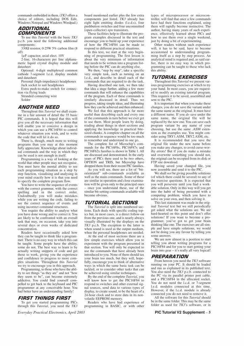
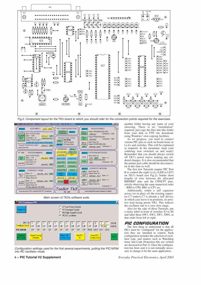
The first few Tutorials require PIC PortB to control the eight l.e.d.s (LD0 to LD7)on TK3’s board (see Fig.2). Solder shortlengths of wire between the allocatedRB0/RB7 pins and the CP0/CP7 pins,strictly observing the same numerical order– RB0 to CP0, RB1 to CP1 etc.
Additionally, solder a 1�F capacitoracross (or in place of) the existing capaci-tor C7 (unless C7 is already a 1�F device,in which case leave it in position), its posi-tive lead facing preset VR1. This reducesthe oscillator rate to a very slow range.
Also for the sake of these Tutorials, puta sticky label in front of switches S3 to S6and label them SW3, SW2, SW1, SW0, inthat order from left to right.
����������������The first thing to understand is that all
PICs must be “configured” for the applica-tion they are intended to control. Suchconfiguration includes the selection of oscil-lator type, and matters such as Watchdogtimer and Code Protection bits use (whichare discussed in Part 3). Once the configura-tion has been sent it is not normally neces-sary to change it for the same application.
SW3 SW2 SW1 SW0
XTAL
RCRC RATERESET
R5
R1
R6
R2
R7
R3
R8
R4
IC2
IC8R14
R15
R16
R13
TR2 TR3 TR4 TR5
CP12
CP13
CP14
CP15
e e e eb b b b
c c c cTP1 TP2 TP3 TP4 TP5 TP6
GP0
GP1
GP2
CP8
CP9
CP10
CP11
CP22
CP7
CP6
CP5
CP4
CP3
CP2
CP1
CP0
LD7 LD6 LD5 LD4 LD3 LD2 LD1 LD0
a
k
a
k
a
k
a
k
a
k
a
k
a
k
a
k
a
k
RM1
CP24
CP23
TP7
TP8
CP25
IC3
IC5
R10
D1a
k
C9
C8
TR1e bc
R11
C12
C2
C1
IC1
C7
VR1
C3
+
+ R12
R9
TP9RE0
RE1
RE2
C11
S3 S4 S5 S6
R20
R17
R19
R18
RD1RD0RD2RD3
RD4
RD5
RD6RD7
RA0RA1
RA2
RA3RA4
RA5
RC0
RC1RC2RC3
CP16 CP17 CP18 CP19CP20
CP21
IC6
RB0RB1RB2
RB3RB4RB5RB6RB7
RC4
RC5RC6
RC7
D7
D6D5
D4
RSE
0V
0V
0V(R/W)
CX+5V
+5V +5VOUT
+7/15V
+7/15V
CLKDATA
MCLR
C10
C4
VR2L.C.D.
CONTRAST
C6
+
C5
IC4IN
COMOUT
IC7
SK1
S1 S2X1
OSC OUT
EXT OSC*
0V
0VOUT
VR3
Fig.2. Component layout for the TK3 board to which you should refer for the connection points required for the exercises.
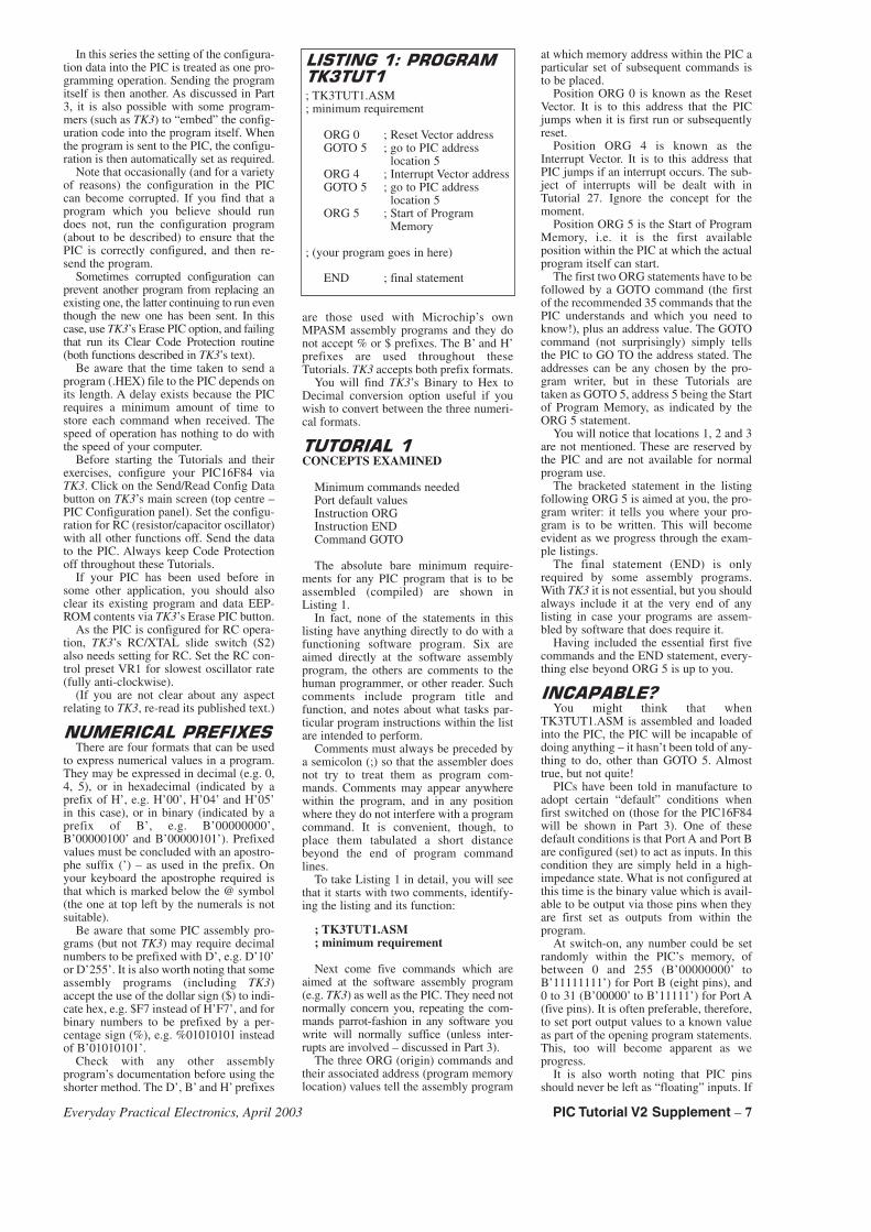
Main screen of TK3’s software suite.
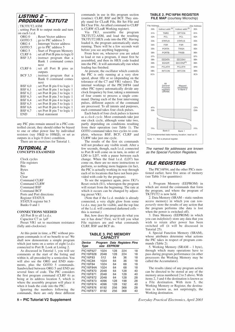
Configuration settings used for the first several experiments, putting the PIC16F84into RC oscillator mode.
6 – PIC Tutorial V2 Supplement Everyday Practical Electronics, April 2003
In this series the setting of the configura-tion data into the PIC is treated as one pro-gramming operation. Sending the programitself is then another. As discussed in Part3, it is also possible with some program-mers (such as TK3) to “embed” the config-uration code into the program itself. Whenthe program is sent to the PIC, the configu-ration is then automatically set as required.
Note that occasionally (and for a varietyof reasons) the configuration in the PICcan become corrupted. If you find that aprogram which you believe should rundoes not, run the configuration program(about to be described) to ensure that thePIC is correctly configured, and then re-send the program.
Sometimes corrupted configuration canprevent another program from replacing anexisting one, the latter continuing to run eventhough the new one has been sent. In thiscase, use TK3’s Erase PIC option, and failingthat run its Clear Code Protection routine(both functions described in TK3’s text).
Be aware that the time taken to send aprogram (.HEX) file to the PIC depends onits length. A delay exists because the PICrequires a minimum amount of time tostore each command when received. Thespeed of operation has nothing to do withthe speed of your computer.
Before starting the Tutorials and theirexercises, configure your PIC16F84 viaTK3. Click on the Send/Read Config Databutton on TK3’s main screen (top centre –PIC Configuration panel). Set the configu-ration for RC (resistor/capacitor oscillator)with all other functions off. Send the datato the PIC. Always keep Code Protectionoff throughout these Tutorials.
If your PIC has been used before insome other application, you should alsoclear its existing program and data EEP-ROM contents via TK3’s Erase PIC button.
As the PIC is configured for RC opera-tion, TK3’s RC/XTAL slide switch (S2)also needs setting for RC. Set the RC con-trol preset VR1 for slowest oscillator rate(fully anti-clockwise).
(If you are not clear about any aspectrelating to TK3, re-read its published text.)
��������������� There are four formats that can be used
to express numerical values in a program.They may be expressed in decimal (e.g. 0,4, 5), or in hexadecimal (indicated by aprefix of H’, e.g. H’00’, H’04’ and H’05’in this case), or in binary (indicated by aprefix of B’, e.g. B’00000000’,B’00000100’ and B’00000101’). Prefixedvalues must be concluded with an apostro-phe suffix (’) – as used in the prefix. Onyour keyboard the apostrophe required isthat which is marked below the @ symbol(the one at top left by the numerals is notsuitable).
Be aware that some PIC assembly pro-grams (but not TK3) may require decimalnumbers to be prefixed with D’, e.g. D’10’or D’255’. It is also worth noting that someassembly programs (including TK3)accept the use of the dollar sign ($) to indi-cate hex, e.g. $F7 instead of H’F7’, and forbinary numbers to be prefixed by a per-centage sign (%), e.g. %01010101 insteadof B’01010101’.
Check with any other assemblyprogram’s documentation before using theshorter method. The D’, B’ and H’ prefixes
are those used with Microchip’s ownMPASM assembly programs and they donot accept % or $ prefixes. The B’ and H’prefixes are used throughout theseTutorials. TK3 accepts both prefix formats.
You will find TK3’s Binary to Hex toDecimal conversion option useful if youwish to convert between the three numeri-cal formats.
���������CONCEPTS EXAMINED
Minimum commands neededPort default valuesInstruction ORGInstruction ENDCommand GOTO
The absolute bare minimum require-ments for any PIC program that is to beassembled (compiled) are shown inListing 1.
In fact, none of the statements in thislisting have anything directly to do with afunctioning software program. Six areaimed directly at the software assemblyprogram, the others are comments to thehuman programmer, or other reader. Suchcomments include program title andfunction, and notes about what tasks par-ticular program instructions within the listare intended to perform.
Comments must always be preceded bya semicolon (;) so that the assembler doesnot try to treat them as program com-mands. Comments may appear anywherewithin the program, and in any positionwhere they do not interfere with a programcommand. It is convenient, though, toplace them tabulated a short distancebeyond the end of program commandlines.
To take Listing 1 in detail, you will seethat it starts with two comments, identify-ing the listing and its function:
; TK3TUT1.ASM; minimum requirement
Next come five commands which areaimed at the software assembly program(e.g. TK3) as well as the PIC. They need notnormally concern you, repeating the com-mands parrot-fashion in any software youwrite will normally suffice (unless inter-rupts are involved – discussed in Part 3).
The three ORG (origin) commands andtheir associated address (program memorylocation) values tell the assembly program
at which memory address within the PIC aparticular set of subsequent commands isto be placed.
Position ORG 0 is known as the ResetVector. It is to this address that the PICjumps when it is first run or subsequentlyreset.
Position ORG 4 is known as theInterrupt Vector. It is to this address thatPIC jumps if an interrupt occurs. The sub-ject of interrupts will be dealt with inTutorial 27. Ignore the concept for themoment.
Position ORG 5 is the Start of ProgramMemory, i.e. it is the first availableposition within the PIC at which the actualprogram itself can start.
The first two ORG statements have to befollowed by a GOTO command (the firstof the recommended 35 commands that thePIC understands and which you need toknow!), plus an address value. The GOTOcommand (not surprisingly) simply tellsthe PIC to GO TO the address stated. Theaddresses can be any chosen by the pro-gram writer, but in these Tutorials aretaken as GOTO 5, address 5 being the Startof Program Memory, as indicated by theORG 5 statement.
You will notice that locations 1, 2 and 3are not mentioned. These are reserved bythe PIC and are not available for normalprogram use.
The bracketed statement in the listingfollowing ORG 5 is aimed at you, the pro-gram writer: it tells you where your pro-gram is to be written. This will becomeevident as we progress through the exam-ple listings.
The final statement (END) is onlyrequired by some assembly programs.With TK3 it is not essential, but you shouldalways include it at the very end of anylisting in case your programs are assem-bled by software that does require it.
Having included the essential first fivecommands and the END statement, every-thing else beyond ORG 5 is up to you.
����������You might think that when
TK3TUT1.ASM is assembled and loadedinto the PIC, the PIC will be incapable ofdoing anything – it hasn’t been told of any-thing to do, other than GOTO 5. Almosttrue, but not quite!
PICs have been told in manufacture toadopt certain “default” conditions whenfirst switched on (those for the PIC16F84will be shown in Part 3). One of thesedefault conditions is that Port A and Port Bare configured (set) to act as inputs. In thiscondition they are simply held in a high-impedance state. What is not configured atthis time is the binary value which is avail-able to be output via those pins when theyare first set as outputs from within theprogram.
At switch-on, any number could be setrandomly within the PIC’s memory, ofbetween 0 and 255 (B’00000000’ toB’11111111’) for Port B (eight pins), and0 to 31 (B’00000’ to B’11111’) for Port A(five pins). It is often preferable, therefore,to set port output values to a known valueas part of the opening program statements.This, too will become apparent as weprogress.
It is also worth noting that PIC pinsshould never be left as “floating” inputs. If
�� ������ ������
�!����
; TK3TUT1.ASM; minimum requirement
ORG 0 ; Reset Vector addressGOTO 5 ; go to PIC address
location 5ORG 4 ; Interrupt Vector addressGOTO 5 ; go to PIC address
location 5ORG 5 ; Start of Program
Memory
; (your program goes in here)
END ; final statement
Everyday Practical Electronics, April 2003 PIC Tutorial V2 Supplement – 7
any PIC pins remain unused in a PIC-con-trolled circuit, they should either be biasedto one or other power line by individualresistors (say 10k� to 100k�), or set asoutputs in a logic 0 (low) condition.
There are no exercises for Tutorial 1.
��������"CONCEPTS EXAMINED
Clock cyclesFile registersBitsBytesSetClearCommand CLRFCommand CLRWCommand BSFCommand BCFPorts and Port directionsRegister STATUSSTATUS register bit 5Banks 0 and 1
CONNECTIONS NEEDEDAll Port B to all l.e.d.s.Capacitor C7 as 1�FPreset VR1 set to maximum resistance
(fully anti-clockwise)
At this point in time, a PIC without pro-gram commands is of no benefit to us! Weshall now demonstrate a simple programwhich just turns on a series of eight l.e.d.sconnected to Port B. Look at Listing 2.
As discussed in Tutorial 1, you will seecomments at the start of the listing andwithin it, all preceded by a semicolon. Youwill also see the ORG and END state-ments, plus the GOTO 5 commands.Sandwiched between ORG 5 and END areseveral lines of code. The PIC considersthe first program command (CLRF 6) asbeing at its address location 5, which iswhere the assembly program will place itwhen it loads the code into the PIC.
Ignoring the numbers following thecommands, there are only three different
commands in use in this program section(routine): CLRF, BSF and BCF. They sim-ply stand for CLeaR File, Bit Set File andBit Clear File. An allied command to CLRFis CLRW (CLeaR Working register).
Via TK3, assemble the programTK3TUT2.ASM, and load the resultingTK3TUT2.HEX code into the PIC. Havingloaded it, the program automatically startsrunning. There will be a few seconds waitbefore you see anything happening.
From here on, whenever you are askedto load or run a program, it must first beassembled, and then its HEX code loadedinto the PIC. It will automatically run whenloading has finished.
At present, the oscillator which controlsthe PIC is only running at a very slowspeed, about 1Hz or so (depending on thetolerance of the C7 and VR1 values). Theinternal workings of the PIC16F84 (andother PIC types) automatically divide anyclock frequency by four, taking a minimumof four counts to process a single com-mand. During each of the four interveningpulses, different aspects of the commandare processed. To all intents and purposes,each command takes four clock pulses.
Each batch of four clock pulses is knownas a clock cycle. Most commands take justone clock cycle, although some take two,partly depending on conditions resultingfrom their operation (see Table 1). TheGOTO command takes two cycles to com-plete, whereas BSF, BCF, CLRF andCLRW take just one cycle.
The results of the first six commandswill not produce any visible result. After afew seconds, though, each l.e.d. connectedto Port B will come on in turn, in order ofLD0 to LD7, with a pause between eachchange. When the final l.e.d. (LD7) hascome on, there are no more instructions toperform, so nothing more happens (in fact,the PIC is actually working its way througheach of its locations that have not been pro-vided with code by the program).
To see the sequence again, press TK3’sReset switch (S1), whereupon the programwill restart from the beginning. The rate atwhich it occurs can be changed by adjust-ing preset VR1.
(Note that if the l.c.d. module is alreadyconnected, a very slight glow from somel.e.d.s. may just be visible, and the top lineof the l.c.d. will contained darkened cells –this is normal.)
But, how does the program do what yousee it has done? First, we’ll tell you whatFile registers are and what commandsCLRF, BSF and BCF do.
�������� ��
The PIC16F84, and the other PICs men-tioned earlier, have five areas of memory(see Table 3 for quantities):
1. Program Memory (EEPROM) inwhich are stored the commands that formthe program, and where the program ofTK3TUT2 is now held.
2. Data Memory (SRAM – static randomaccess memory) in which you can tem-porarily store the results of any action thatthe program performs (the data is lostwhen the power is switched off).
3. Data Memory (EEPROM) in whichyou can indefinitely store any data that youwish to retain after power has beenswitched off (it will be discussed inTutorial 25).
4. Special Function Memory (SRAM),whose attributes determine what actionsthe PIC takes in respect of program com-mands (Table 2).
5. Working Memory (SRAM – 1 byte),through which many operations have topass during program performance (in otherprocessors the Working Memory may becalled the Accumulator).
The results (data) of any program actioncan be directed to be stored at any of thememory areas numbered 2 to 5 above. Withitems 2, 3 and 4 the destination is known asa File destination. With item 5, theWorking Memory or Register, the destina-tion is known as, not surprisingly, theWorking destination.
�� �����"�#
�������!���"
; TK3TUT2.ASM; setting Port B to output mode and turnon each l.e.d.
ORG 0 ; Reset Vector addressGOTO 5 ; go to PIC address 5ORG 4 ; Interrupt Vector addressGOTO 5 ; go to PIC address 5ORG 5 ; Start of Program MemoryCLRF 6 ; set all Port B pins to logic 0BSF 3,5 ; instruct program that a
Bank 1 command comesnext
CLRF 6 ; set all Port B pins asoutputs
BCF 3,5 ; instruct program that aBank 0 command comesnext
BSF 6,0 ; set Port B pin 0 to logic 1BSF 6,1 ; set Port B pin 1 to logic 1BSF 6,2 ; set Port B pin 2 to logic 1BSF 6,3 ; set Port B pin 3 to logic 1BSF 6,4 ; set Port B pin 4 to logic 1BSF 6,5 ; set Port B pin 5 to logic 1BSF 6,6 ; set Port B pin 6 to logic 1BSF 6,7 ; set Port B pin 7 to logic 1END ; final statement
TABLE 3. PIC MEMORYCAPACITY
Device Program Data Registers PinsType size EEPROM
PIC16F627 1024 128 224 18PIC16F628 2048 128 224 18PIC16F83 512 64 36 18PIC16C84 1024 64 36 18PIC16F84 1024 64 68 18PIC16F84A 1024 64 68 18PIC16F870 2048 64 128 40PIC16F871 2048 64 128 40PIC16F872 2048 64 128 28PIC16F873 4096 128 198 28PIC16F874 4096 128 192 40PIC16F876 8192 256 368 28PIC16F877 8192 256 368 40
TABLE 2. PIC16F84 REGISTERFILE MAP (courtesy Microchip)
The named file addresses are knownas the Special Function Registers.
8 – PIC Tutorial V2 Supplement Everyday Practical Electronics, April 2003
Strictly speaking, Files should be knownby their full name of File Registers. Itwould be tedious, though, to keep using thefull name, and so the term “file” will beused throughout the Tutorials to mean FileRegister. (We also use the term “file” inrelation to disk files – the context shouldmake the meaning clear.)
For those of you who are familiar withprogramming in BASIC, files can beregarded as the equivalent of variables.There is no direct BASIC equivalent of theWorking register, though in a sense it canbe regarded as a special variable.
The program commands reflect the fileand working destinations by the use of Fand W, respectively, in the code itself. Forexample, in the code CLRF, the F indi-cates that the value in a particular file(memory data byte) is to be CLeaRed(reset to zero) and the result is to beretained in the file. On the other hand, inthe code MOVLW (to be met in Tutorial 4)the W stands for Working (in this casemeaning that a Literal value is to beMOVed into W). The use of both F and Win a command (e.g. MOVWF) will becomeevident in due course.
��� Having established what a file is, it is
necessary (and easy) to understand theconcept of a “bit”. You no doubt under-stand it already, but, just to recap, a bit isa single part of an electronic memorywhich can be set to one of two states:either to logic 1 (“on” – charged to a volt-age which is usually the same as the posi-tive power rail that supplies the circuit,e.g. +5V); or to logic 0 (“off” – dis-charged to a zero voltage). Logic 1 andlogic 0 are often referred to as high andlow, respectively.
A memory i.c. can have any number ofbits contained within it. A fixed number ofbits is known as a “byte”. There is a com-mon misconception that a byte is only evercomprised of eight bits. Historically, this isnot true, any fixed number of bits whichcan be operated as a single unit is called abyte. However, by current usage, a byte isusually taken to be comprised of eight bits.
The status of the bits (high or low) with-in a byte is expressed as a binary numberreading from left to right, in order of the bitrepresenting the highest value first (mostsignificant bit – MSB) down to the lowestvalue (least significant bit – LSB). Thusdecimal 128 is expressed as binary10000000, whereas binary 1 may beexpressed as 00000001 (the precedingnumber of zeros may not always be includ-ed – their presence being implied).
The bits of a byte are referred to by theirposition within a byte, with position 0 atthe right, ascending as high as necessarydepending on the byte length. Thus an 8-bitbyte has its bits numbered as 7, 6, 5, 4, 3,2, 1, 0. A 16-bit byte (probably referred toas a word) would be numbered from 15 to0. The use of 0 (zero) as a bit number isessential to remember when programmingPICs.
Incidentally, terms MSB and LSB canalso be used to mean Most Significant Byteand Least Significant Byte. The appropri-ate meaning should be clear from the con-text. There are also similar terms, NSB,NMSB and NLSB, in which the N standsfor Next.
��� � ����������
The concept of the terms “set” and “clear”is important to understand. In programterms, to “set” a bit means to force it high,i.e. to logic 1; the term “clear” is used tomean that a bit is forced low, i.e. to logic 0.
Note, however, that in textual terms (i.e.in articles such as this) you are likely tocome across the mixed use of the word“set”, in that you might be told to “set a bitlow”. In such cases, the implied meaningshould be obvious from the context. In thisexample, “low” is the important word and“force” or “make” could have been usedinstead of “set”.
������� ������� ���
Command CLRF stands for CLeaR Fileand is always followed by a single numberor name which indicates the file on whichthe action is to be performed. The com-mand instructs the PIC that all bits withinthe stated file are to be cleared, i.e. it clearsthe whole byte (to hold a value of zero).
The allied command CLRW (CLeaRWorking register) simply clears the contentsof the Working register and is used on its ownwithout a subsequent number or name. Inpractice, this command may be seldom used,the commands MOVLW 0 and RETLW 0probably finding preference (these com-mands are discussed in Tutorials 4 and 13,respectively). Command CLRW has, in fact,been dropped from some PIC families.
There are no direct opposites of CLRFand CLRW which will set all bits high;other techniques have to be used for thisaction.
Using names for files instead of numberswill be dealt with in Tutorial 3.
��������� �PICs can have any individual bit of any
file byte acted upon directly. Each bit can
be set high or low by a single command,and, as we shall show later, a single com-mand will also determine the status of anyindividual bit.
Command BSF translates as Bit Set Fileand is always followed by two numbers ornames separated by a comma. The firstnumber or name is the file byte whose bitis to be acted upon. The second number orname is that representing the number of thebit within the file byte (between 7 and 0,reading from left to right).
As an example, the command BSF 3,5 inListing 2 instructs the PIC to set (makehigh, force to logic 1!) bit 5 of file number3; command BSF 6,7 means that bit 7 offile number 6 is to be set.
�����������Command BCF stands for Bit Clear File
and is the exact opposite of BSF. As anexample, the command BCF 3,5 in Listing2 means that bit 5 of file 3 is to be cleared(set low, made/forced to logic 0!).
�������������� In the example of Listing 2, the files
whose bits have been set or cleared arethose which control Port B. In terms ofwriting to or reading from Port A and PortB, the two ports are treated as any other filedestination. However, Port A and Port Bare different to other files in that they arefor communication with the outside world.
There are, in fact, two file registers asso-ciated with each port that are accessible tothe programmer. One is used to set thedirection in which the bits are to act, i.e. asinputs or outputs (it is also known as theData Direction Register – DDR), and theother deals with the data written to (for out-put to the world) or read from (input fromthe world). Each bit of the port directionregisters can be individually set or clearedso that the same port may be used simulta-neously for data input and output viadifferent bits.
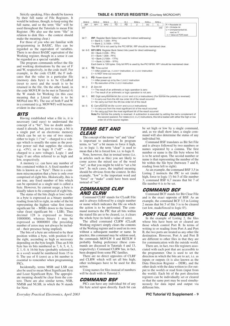
TABLE 4: STATUS REGISTER (Courtesy MICROCHIP)
Everyday Practical Electronics, April 2003 PIC Tutorial V2 Supplement – 9
The file which controls the direction inwhich Port B pins respond is named in thePIC datasheets as TRISB. It is one of thenamed “Special Function Register” files(see Table 2) and is contained in memorybyte address H’86’ (we won’t translatehexadecimal numbers into decimal sincethe latter are irrelevant in the context of fileaddresses).
The file which holds Port B’s data,whether as input or output, is at memorybyte address H’06’ and, helpfully, is knownin the PIC datasheet as PORTB.
A minor inconvenience exists in thePIC16F84, and the other PIC familiesreferred to earlier, in that addresses H’80’to H’8B’ can only be accessed by changingthe value in another file, the STATUS file(Table 4). This file is held jointly at byteaddresses H’03’ and H’83’. A single bitwithin STATUS is used to direct the pro-gram to numbers either below H’80’(known as Bank 0 or Page 0 addresses) orabove H’7F’ (known as Bank 1 or Page 1addresses); this bit is number 5. (Note thatsome PICs have more than two Banks.)
When STATUS bit 5 is set (logic 1), iteffectively adds H’80’ to the memory byteaddress being accessed. When the bit isclear (logic 0), addresses below H’80’ areaccessed. Thus, if you instruct that file 6(H’06’) is to be accessed when STATUSbit 5 is low, the file actually at address 6will be accessed. Conversely, if youinstruct that file 6 is the subject when STA-TUS bit 5 is high, the file at address H’86’will be accessed.
In the PIC16F84, only files numberedH’00’ to H’4F’ and H’80’ to H’8B’ areavailable for use by the programmer. Notethat files H’07’ and H’87’ have no function.
It may appear from the Registers FileMap in Table 2 that addresses H’8C’ toH’CF’ might also be available. Writing tothese addresses, though, simply accessesthose between H’0C’ and H’4F’. (In somePICS, including the PIC16F87x andPIC16F62x families, additional memory isavailable at the higher Bank addresses –see Using the PIC16F87x AdditionalMemory, EPE June ’02, on the CD-ROM.)
�� �����"��������
We can now examine each command ofListing 2 in turn and describe its purpose.When the PIC is first switched on, theSTATUS file is set to a default value withits bit 5 low. All file addresses are thustreated as being below H’80’.
We have established that address 6 isthat which holds the data for Port B. Thefirst command, CLRF 6, thus clears thedata which is held in Port B as a valueavailable to be output, i.e. Port B’s outputregister is instructed to hold a value ofzero.
The purpose of the program in Listing 2is to output data to the eight l.e.d.s on PortB, and it has already been said that thedefault value of Port B’s direction register(at H’86’) is for all bits to be set for input(all bits are high – 11111111).Consequently we must now set them all asoutputs, i.e. each to logic 0, thus 00000000.To do this, first the STATUS register ataddress 3 must have its bit 5 set high topoint to addresses of H’80’ and above;hence the command BSF 3,5.
Now we configure all of Port B for out-put mode with the command CLRF 6. Yes,
it’s the same command as cleared Port B’sdata, but because STATUS bit 5 is high, thevalue of 6 (H’06’) has H’80’ added to it, sothe address actually accessed is that atH’86’.
The commands which output data to thel.e.d.s are all concerned with Port B’s datafile at “real” address 6, so the addition ofH’80’ is no longer needed. The next com-mand, BCF 3,5, thus clears bit 5 of theSTATUS register at address 3. All remain-ing commands in Listing 2 can now, inturn, set high each data bit of Port B ataddress 6: BSF 6,0, BSF 6,1, etc., so turn-ing on the l.e.d.s in sequence from LD0 toLD7. Simple!
����� ��"
2.1. Using your text editor and a copy ofTK3TUT2.ASM (renamed to any title ofyour choosing, but still with the .ASMextension), experiment with the eightcommands relating to file 6, using differentvalues (between 0 and 7) for the numberfollowing the comma. Do not change thenumber before the comma. Also experi-ment with changing BSF to BCF.
2.2. Rewrite the program in Listing 2 sothat it performs its actions on Port Ainstead of Port B. The equivalent data anddirection addresses for Port A are 5 (H’05’)and H’85’, respectively. Note that Port A
�� �����!�#��������!���!
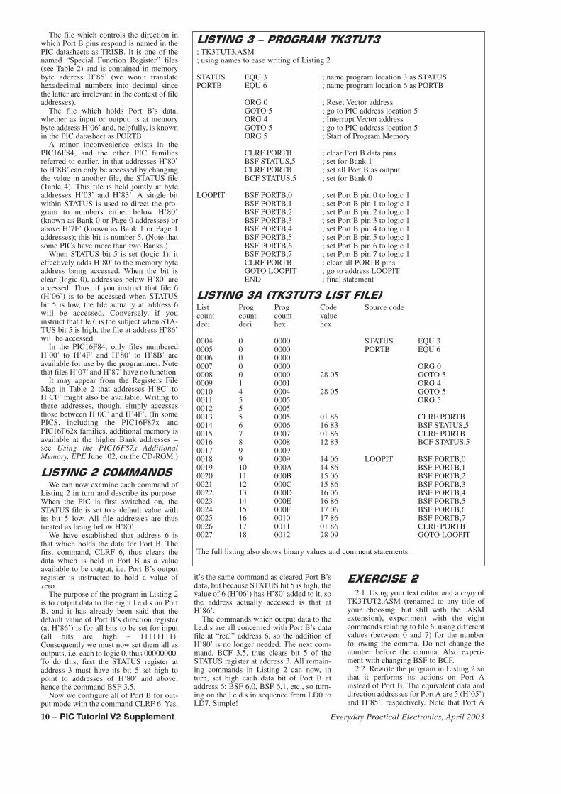
; TK3TUT3.ASM; using names to ease writing of Listing 2
STATUS EQU 3 ; name program location 3 as STATUSPORTB EQU 6 ; name program location 6 as PORTB
ORG 0 ; Reset Vector addressGOTO 5 ; go to PIC address location 5ORG 4 ; Interrupt Vector addressGOTO 5 ; go to PIC address location 5ORG 5 ; Start of Program Memory
CLRF PORTB ; clear Port B data pinsBSF STATUS,5 ; set for Bank 1CLRF PORTB ; set all Port B as outputBCF STATUS,5 ; set for Bank 0
LOOPIT BSF PORTB,0 ; set Port B pin 0 to logic 1BSF PORTB,1 ; set Port B pin 1 to logic 1BSF PORTB,2 ; set Port B pin 2 to logic 1BSF PORTB,3 ; set Port B pin 3 to logic 1BSF PORTB,4 ; set Port B pin 4 to logic 1BSF PORTB,5 ; set Port B pin 5 to logic 1BSF PORTB,6 ; set Port B pin 6 to logic 1BSF PORTB,7 ; set Port B pin 7 to logic 1CLRF PORTB ; clear all PORTB pinsGOTO LOOPIT ; go to address LOOPITEND ; final statement
�� �����!��$�!���!��� ������%
List Prog Prog Code Source codecount count count valuedeci deci hex hex
0004 0 0000 STATUS EQU 30005 0 0000 PORTB EQU 60006 0 00000007 0 0000 ORG 00008 0 0000 28 05 GOTO 50009 1 0001 ORG 40010 4 0004 28 05 GOTO 50011 5 0005 ORG 50012 5 00050013 5 0005 01 86 CLRF PORTB0014 6 0006 16 83 BSF STATUS,50015 7 0007 01 86 CLRF PORTB0016 8 0008 12 83 BCF STATUS,50017 9 00090018 9 0009 14 06 LOOPIT BSF PORTB,00019 10 000A 14 86 BSF PORTB,10020 11 000B 15 06 BSF PORTB,20021 12 000C 15 86 BSF PORTB,30022 13 000D 16 06 BSF PORTB,40023 14 000E 16 86 BSF PORTB,50024 15 000F 17 06 BSF PORTB,60025 16 0010 17 86 BSF PORTB,70026 17 0011 01 86 CLRF PORTB0027 18 0012 28 09 GOTO LOOPIT
The full listing also shows binary values and comment statements.
10 – PIC Tutorial V2 Supplement Everyday Practical Electronics, April 2003
only has five pins, not eight. What differ-ence, if any, does this make to the pro-gram? You need to disconnect the wiresfrom Port B that go to l.e.d.s LD0 to LD4,and then connect Port A pins to these l.e.d.sin correct numerical order.
You will notice that Port A pin RA4 doesnot appear to turn on its l.e.d. This isbecause the pin has an “open-collector”output which needs to be biased high,before it can be used to toggle betweenLogic 0 and Logic 1. An example of this isshown in Tutorial 12.
Reinstate the Port B connections to alll.e.d.s when you have finished withExercise 2.2.
��������!CONCEPTS EXAMINED
Names in place of numbersLabelsCase sensitivityA repetitive loopInstruction EQU
CONNECTIONS NEEDEDAll Port B to all l.e.d.s.Capacitor C7 as 1�FPreset VR1 set to maximum resistance
(fully anti-clockwise)
In the previous section dealing withListing 2, we were using numbers to indi-cate which file was being referred to.That’s fine if there are only a few fileswhose address numbers can be easilyremembered. As we progress with examin-ing the PIC commands and example list-ings, though, we shall be using more andmore files. If we continue to refer to themnumerically, we’re going to get lost!(What’s file H’0C’ for? Is the data sup-posed to go to file H’1C’ or file H’1E’?)
Human memories with numbers arenotoriously bad! But we are (usually)much better with names. This fact was longago recognised by program writers andmany types of software allow the use ofnames in place of numbers. Let’s examinehow names can be applied to the numberedfiles in Listing 2. Have a look at Listing 3.
Any number written into a listing can berepresented by a name. It can be any nameyou like as long as you think you’ll knowin time to come what is meant by that name(but some assembly programs impose alimit on name lengths, although TK3 doesnot). There are also some names which it isbetter to allocate according to their func-tion, especially those functions that alreadyhave names provided in the PIC datasheets,such names as STATUS and PORTB, forexample.
With some programmers (but not TK3),the names are “case-sensitive”. In otherwords, once you have equated a name witha number, further use of the name must bein exactly the same style as the originalwith regard to the use of upper and lowercase letters. For example, names PORTBand portb should not be used interchange-ably. It is recommended, though, that youdo not use different upper and lower casestyles of the same word to mean differentthings.
However, the commands themselves (asopposed to the names) may be in upper orlower case without (usually) causingproblems. For example, for clarity on these
published pages, the commands are shownin upper case. In the actual full ASM list-ings, though, the same commands are prin-cipally in lower case – the TK3 assemblyprogram recognises both styles.
�&����������� In Listing 3, three names have appeared:
the aforementioned “aliases” STATUS andPORTB, plus LOOPIT. We’ll keep LOOP-IT a mystery for the moment (but we’resure you know what it’s for). All “alias”name allocations must appear at the headof the program listing, in the initialisationblock.
Then the format for allocating a nameto a number is to state the name at the leftof a program line followed by at least onespace, although you may have more thanone space if you prefer, to keep thingslooking neat and tabulated. Most assem-bly programs allow the use of the Tab keyto keep columns tabulated, which makestyping easier than keying-in lots ofspaces.
Now the statement EQU is made, fol-lowed by a space and the number you wishto name. In the case of the first line,STATUS is the name to be given to thenumeral 3 (which, you will remember, isthe file address number for the STATUSregister). Hence, the statement:
STATUS EQU 3
This simply tells the assembler programthat when it assembles the listing into code,each time it comes across the nameSTATUS, it is to replace it in the code bythe value of decimal 3.
The second line similarly allocates thename PORTB to file address 6:
PORTB EQU 6
Compare Listing 2 and Listing 3; youwill see how the program has beenrewritten using the names in place of filenumbers.
It is permissible to use other numericalformats, such as binary and hexadecimal,in EQU number defining.
�� ��$'� �%����� When ASM source code files are assem-
bled, a List file (.LST) is generated as wellas the HEX file. A list file allows examina-tion of the original ASM source code andthe actual values that the assembly pro-gram generates in respect of that code.
Some assemblers generate separate listfiles for each source code file, using thesame basic file name, but giving an exten-sion of .LST. TK3, though, uses a commonfile name that is used for all list files(TK3ASM.LST).
Click on the LIST button in TK3’sAssembly zone to open the LST file creat-ed when TK3TUT2.ASM was assembled,and print it to paper. Then assembleTK3TUT3.ASM and print out its LST file.A section of it is repeated in Listing 3A.
Examining both printouts you will seethat the Program Count and Code Valuehex numbers are the same in both listings,except for the last two (new) commands ofTK3TUT3.
The LST files also include the program-mer’s notes at the right. They have beenomitted from Listing 3A to conserve space.
The lefthand column (List count deci)holds the text line numbers as encounteredin the text file listing (ASM) and are indecimal. They serve no programmingpurpose and are simply there for yourinformation.
The second and third columns show theactual address location number (in decimaland hex respectively) within the PIC atwhich the command will be placed.
Command ORG 0 causes its associatedGOTO 5 statement to be coded at location0, similarly with ORG 4 and its GOTO 5statement for location 4.
Note how columns four and five, whichhold the 2-byte hex code and the equivalentbinary (14-bit) value (not shown in Listing3A), are only used if a command isencountered. For example, commandGOTO 5 generates the code 28 05(H’2805’), and command CLRF PORTBgenerates the code 01 86 (H’0186’).
The .HEX file holds the code values inhexadecimal. The 14-bit binary value isthat which is converted from the hex valueand sent to the PIC as serial data.
�!���!������(Now load the code for TK3TUT3.HEX
into your PIC. It will be seen to start off inthe same way as TK3TUT2. Now, though,when it gets to the end of the code, thel.e.d.s will all go out and the sequence willrepeat, indefinitely! You will find that afully-clockwise setting of VR1 becomespreferable, to increase the display rate.
The program difference now is that thereare two extra commands and when com-mand BSF PORTB,7 has been performed,Port B is cleared and the program followsthe command GOTO LOOPIT. LOOPIT isthe name given to the address at which thecommand BSF PORTB,0 has been placed.During assembly that address number hasbeen noted and each time the assemblerencounters a command reference to theaddress named LOOPIT, it substitutes thenumber for that address. There is just onereference in this program, but other pro-grams may have many such references.
Names, when given to program listingaddresses, as with LOOPIT here, are com-monly known as “labels”. Referring to the.LST listing for TK3TUT3, the numberedline 0018 reads:
0018 9 0009 14 06 LOOPIT BSF PORTB,0
Note the value 9 in column 3. Now lookat line 0027, which reads:
0027 18 0012 28 09 GOTO LOOPIT
Now note the 09 in column 5. The twovalues are equal and intentional. Theaddress for which LOOPIT is the referencename (label) is at location 9; the code 28 09contains the instruction to GOTO (jumpto), plus the address number to which it isto jump.
In other instances, the addresses may bemuch greater than the one illustrated here,and the two values will differ accordingly,but the point is that the name LOOPIT isreplaced by an address value during assem-bly and as such is treated by the Assemblerin the same way as were STATUS andPORTB.
This fact has another important signifi-cance: when a number has a name
Everyday Practical Electronics, April 2003 PIC Tutorial V2 Supplement – 11
allocated to it, each time the assemblyprogram encounters that name it substi-tutes the appropriate number. Names canbe given to addresses (as just illustrated),to register files (as with PORTB), andeven bit numbers (Z to represent the Zeroflag bit of the STATUS register, as shownlater).
We shall also show examples of namesbeing used as pointers to addresses whenthe address required may depend on a par-ticular value established as a result of cal-culation, i.e. in the case of IndirectAddressing, which will be examined inTutorial 16.
It is worth noting that TK3 allows labelsto be suffixed by a colon (:), e.g. LOOP:,which makes labelled routines easier tofind using a text editor’s Search or Findfacility in a long program that has manycalls to a particular label. Microchip’sassembly programs do not permit this.
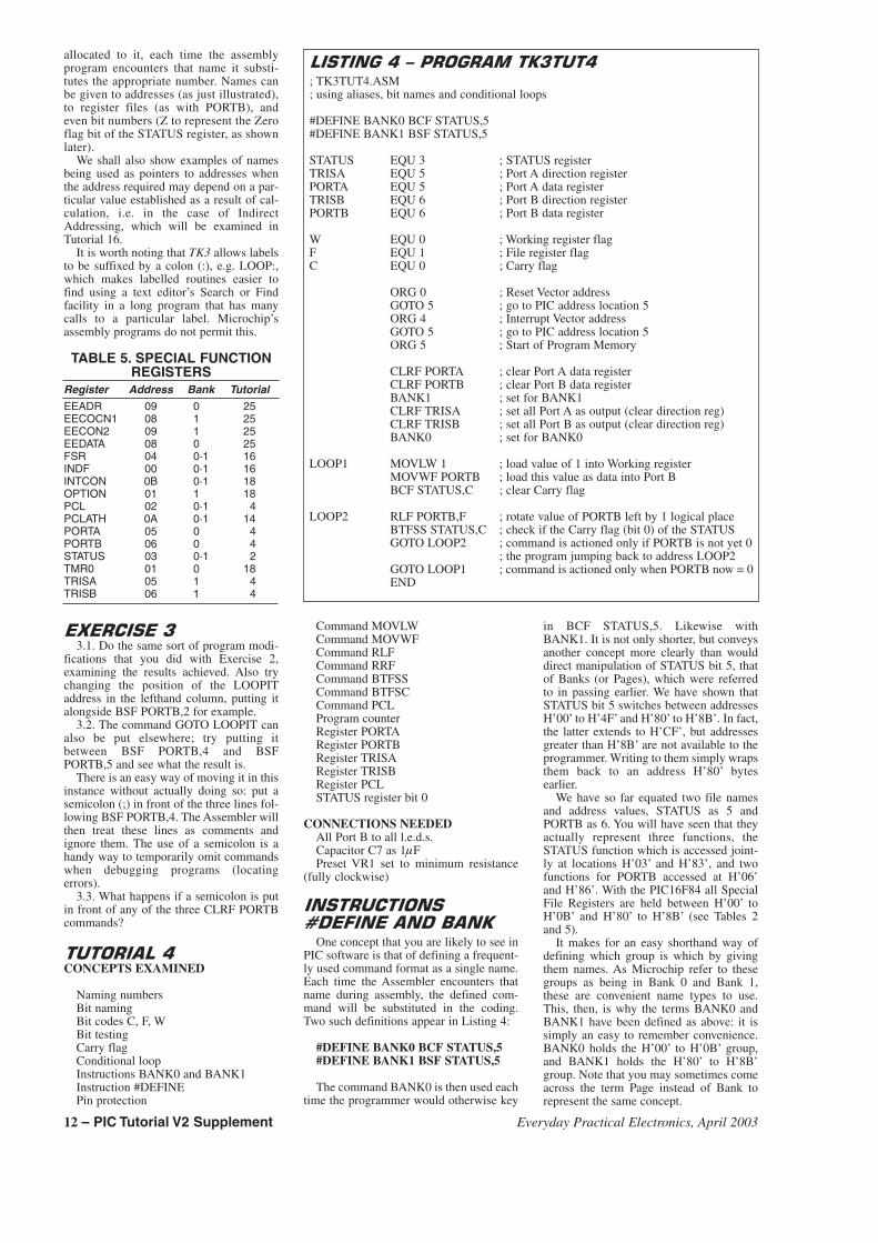
TABLE 5. SPECIAL FUNCTIONREGISTERS
Register Address Bank TutorialEEADR 09 0 25EECOCN1 08 1 25EECON2 09 1 25EEDATA 08 0 25FSR 04 0·1 16INDF 00 0·1 16INTCON 0B 0·1 18OPTION 01 1 18PCL 02 0·1 4PCLATH 0A 0·1 14PORTA 05 0 4PORTB 06 0 4STATUS 03 0·1 2TMR0 01 0 18TRISA 05 1 4TRISB 06 1 4
����� ��!3.1. Do the same sort of program modi-
fications that you did with Exercise 2,examining the results achieved. Also trychanging the position of the LOOPITaddress in the lefthand column, putting italongside BSF PORTB,2 for example.
3.2. The command GOTO LOOPIT canalso be put elsewhere; try putting itbetween BSF PORTB,4 and BSFPORTB,5 and see what the result is.
There is an easy way of moving it in thisinstance without actually doing so: put asemicolon (;) in front of the three lines fol-lowing BSF PORTB,4. The Assembler willthen treat these lines as comments andignore them. The use of a semicolon is ahandy way to temporarily omit commandswhen debugging programs (locatingerrors).
3.3. What happens if a semicolon is putin front of any of the three CLRF PORTBcommands?
���������CONCEPTS EXAMINED
Naming numbersBit namingBit codes C, F, WBit testingCarry flagConditional loopInstructions BANK0 and BANK1Instruction #DEFINEPin protection
Command MOVLWCommand MOVWFCommand RLFCommand RRFCommand BTFSSCommand BTFSCCommand PCLProgram counterRegister PORTARegister PORTBRegister TRISARegister TRISBRegister PCLSTATUS register bit 0
CONNECTIONS NEEDEDAll Port B to all l.e.d.s.Capacitor C7 as 1�FPreset VR1 set to minimum resistance
(fully clockwise)
�� �������
)��������������
One concept that you are likely to see inPIC software is that of defining a frequent-ly used command format as a single name.Each time the Assembler encounters thatname during assembly, the defined com-mand will be substituted in the coding.Two such definitions appear in Listing 4:
#DEFINE BANK0 BCF STATUS,5#DEFINE BANK1 BSF STATUS,5
The command BANK0 is then used eachtime the programmer would otherwise key
in BCF STATUS,5. Likewise withBANK1. It is not only shorter, but conveysanother concept more clearly than woulddirect manipulation of STATUS bit 5, thatof Banks (or Pages), which were referredto in passing earlier. We have shown thatSTATUS bit 5 switches between addressesH’00’ to H’4F’ and H’80’ to H’8B’. In fact,the latter extends to H’CF’, but addressesgreater than H’8B’ are not available to theprogrammer. Writing to them simply wrapsthem back to an address H’80’ bytesearlier.
We have so far equated two file namesand address values, STATUS as 5 andPORTB as 6. You will have seen that theyactually represent three functions, theSTATUS function which is accessed joint-ly at locations H’03’ and H’83’, and twofunctions for PORTB accessed at H’06’and H’86’. With the PIC16F84 all SpecialFile Registers are held between H’00’ toH’0B’ and H’80’ to H’8B’ (see Tables 2and 5).
It makes for an easy shorthand way ofdefining which group is which by givingthem names. As Microchip refer to thesegroups as being in Bank 0 and Bank 1,these are convenient name types to use.This, then, is why the terms BANK0 andBANK1 have been defined as above: it issimply an easy to remember convenience.BANK0 holds the H’00’ to H’0B’ group,and BANK1 holds the H’80’ to H’8B’group. Note that you may sometimes comeacross the term Page instead of Bank torepresent the same concept.
�� �������#��������!����
; TK3TUT4.ASM; using aliases, bit names and conditional loops
#DEFINE BANK0 BCF STATUS,5#DEFINE BANK1 BSF STATUS,5
STATUS EQU 3 ; STATUS registerTRISA EQU 5 ; Port A direction registerPORTA EQU 5 ; Port A data registerTRISB EQU 6 ; Port B direction registerPORTB EQU 6 ; Port B data register
W EQU 0 ; Working register flagF EQU 1 ; File register flagC EQU 0 ; Carry flag
ORG 0 ; Reset Vector addressGOTO 5 ; go to PIC address location 5ORG 4 ; Interrupt Vector addressGOTO 5 ; go to PIC address location 5ORG 5 ; Start of Program Memory
CLRF PORTA ; clear Port A data registerCLRF PORTB ; clear Port B data registerBANK1 ; set for BANK1CLRF TRISA ; set all Port A as output (clear direction reg)CLRF TRISB ; set all Port B as output (clear direction reg)BANK0 ; set for BANK0
LOOP1 MOVLW 1 ; load value of 1 into Working registerMOVWF PORTB ; load this value as data into Port BBCF STATUS,C ; clear Carry flag
LOOP2 RLF PORTB,F ; rotate value of PORTB left by 1 logical placeBTFSS STATUS,C ; check if the Carry flag (bit 0) of the STATUSGOTO LOOP2 ; command is actioned only if PORTB is not yet 0
; the program jumping back to address LOOP2GOTO LOOP1 ; command is actioned only when PORTB now = 0END
12 – PIC Tutorial V2 Supplement Everyday Practical Electronics, April 2003
��������&������In Listing 4, following the three defini-
tions we see STATUS, PORTA andPORTB being nominated (EQUated) as inListing 3, representing register addresses 3,5 and 6 respectively. The names TRISAand TRISB have crept in, though, and theyalso relate to register addresses 5 and 6respectively. Why two names for the samenumber? It is done for the convenient rea-son that we know address 6, for example,relates to registers which appear in bothBANK0 and BANK1, but which have dif-ferent functions, Port B’s data and direc-tion registers, respectively.
It saves confusion, therefore, to have adifferent name for each, even though theiraddress numerals are the same. The nameTRISB is given to Port B’s direction regis-ter since this is the name given to that func-tion in PIC datasheets. The name PORTBnow simply refers to Port B’s data register.Exactly the same convention is applied toPort A, using PORTA and TRISA as thenames in relation to location 5.
Incidentally, as mentioned earlier, there isa command TRIS available as part of thecommand set of some early PICs. Microchiprecommend that it should not be used sinceit has been deleted from the PIC16F84 andlater chips. The same applies to the com-mand OPTION. Neither of these commandswill be discussed here. You will see the useof TRISA, TRISB and OPTION_REG inthis Tutorial, but the terms are used asRegister file names, not as commands.
Where Special Function registers havehad their functions equated to a name thatis similar, henceforth the new name will beused. For example, Port B will be referredto as PORTB, Port A as PORTA and Statusas STATUS. Additionally, in order to avoidrepetition of comments made in earlier list-ings, from now on listing comments willnot always be shown here for situationsthat have previously been discussed. Thefull listings, however, show commentswhere appropriate.
�������������It was said earlier that unused PIC pins
should never be left as “floating” inputs.The easiest way to ensure that they are notis to set them as outputs and to set theiroutput value to 0. This is why PORTA andTRISA conditions have been specified,even though PORTA is not actually used inprogram TK3TUT4.
�������� All the numerals to which names have
been allocated so far have been related tofile (register) byte addresses. It is equallypossible to allocate names to particular bitsin a file byte. This is especially usefulwhen individual bits of particular files per-form specific functions. Three examplesare shown in Listing 4:
C EQU 0W EQU 0F EQU 1
�������� ��������We have already said that data can be
routed either to files or retained in theWorking register. A single bit code, either 0or 1, determines which destination. This bitvalue statement is required following thecomma used with some commands.
For example, take the two similar com-mands RLF PORTB,0 and RLF PORTB,1,the command RLF (which is discussed in amoment) tells the PIC that the value withinthe file then stated (in this case the file isPORTB) is to be rotated left (multiplied bytwo). The result of this rotation can eitherbe put back into PORTB, using the 1 suf-fix, or held in the Working register for fur-ther use, using the 0 suffix. If the Workingregister is chosen, the value in PORTBremains as it was.
Again for easy human understanding, itis more convenient to give a name to thedifferent conditions than having to remem-ber numbers. So the file destination 1 iscalled F for File, and the Working destina-tion 0 is called W for Working. All verylogical and clear! The two example com-mands thus become RLF PORTB,W andRLF PORTB,F.
����������
One bit of STATUS (see Table 4), bit 0,is the bit which indicates whether a Carry ora Borrow has occurred during some com-mands. (It is, incidentally, common to referto such bits as being “flags”: the flag is thensaid to be set or cleared by any action whichaffects it.) The Carry flag is frequentlyrequired to be read in most programs and itis convenient to also give it a name, in thiscase C, hence the setting-up statement:
C EQU 0
The bit can be manipulated or tested bycommands such as BCF STATUS,C orBTFSS STATUS,C (discussion of BTFSScomes in a jiffy or two).
Before going any further with the con-tents of Listing 4, load its code into the PIC(TK3TUT4.HEX). What you will see isthat the eight individual l.e.d.s on PORTBare being turned on at the same time thepreceding one is turned off. The movementwill appear to be going from right to left,from bit 0 to bit 7 (LD0 to LD7), andrestarting at bit 0.
There are several ways of doing this (andmany reasons why you should need to).Two programming techniques are discussedhere, the one in Listing 4, and then a muchshorter one later in Listing 5. The one inListing 4 demonstrates the use of the com-mands MOVLW, MOVWF, RLF, BTFSS,and how two loops can be “nested” andmade dependent upon each other.
������� ������ �
Many of you will be familiar with theelectronic concept of shift register chips.Data can be loaded into the register eitherserially (bit entry) or in parallel (byteentry). The data can be shifted to the “left”or “right” in the chip, in response to a clocksignal. The shifted data can then be madeavailable either serially as bits, or in paral-lel as a byte. When data is shifted left andread as a byte (parallel output), each shifthas the effect of multiplying the data bytwo. Shifting to the right divides it by two.
Take the 8-bit binary code 00000100(decimal 4), for example. If this is shiftedleft by one place, the result is 00001000(decimal 8). If the code had been shiftedright by one place, the result would be00000010 (decimal 2).
Most files within a PIC are capable ofhaving their data shifted (rotated) to the leftor to the right (although doing so on theSpecial Function Registers may sometimesproduce unpredictable results). The twocommands are RLF and RRF (Rotate LeftFile and Rotate Right File).
Both commands have to be followed bythe file which is to have its data rotated,then a comma and then the destination,either F or W. For example: RLF PORTB,For RLF PORTB,W. If the W destination ischosen, the original contents of the fileremain intact (the result going into W); theyare only changed if the F suffix is used,which causes the result to be placed backinto the file, over-writing its previous value.
There are two problems associated withrotating a file’s contents left or right. Forthe first, consider the situation when a file(for the sake of example, call it PORTB)contains a value such as 11010111 (deci-mal 215); there are many numbers thatcould illustrate the point about to be made.Suppose the rotate left command RLFPORTB,F is given, all bits are rotated leftby one place. The value retained in PORTBbecomes 10101110 (decimal 174) which isdefinitely not 2 × 215; the original lefthandbit has vanished from this 8-bit byte – a9-bit byte would be needed to show thecorrect answer.
������������Alternatively, suppose the rotate right
command RRF PORTB,F is given, all bitsare rotated right by one place. The valueretained in PORTB becomes 01101011(decimal 107), which is definitely not215/2; the original right-hand bit has van-ished from this 8-bit byte.
In some cases, of course, the intention ofrotating left or right may have nothing todo with multiplying a value by 2. It may bethat we simply want to change the positionof the bits for another purpose, such aschanging the commands sent to the outsideworld to turn equipment on or off. In thiscase, the arithmetic accuracy of the rotateresult would be immaterial.
The other problem (although it can beused beneficially) is that bits rotated outfrom either end of the byte are rotated intothe Carry bit of STATUS. Simultaneously,the previous value held in the Carry bit isrotated into the byte at the other end.
Suppose that the Carry bit is initiallyzero. In the first RLF example above, theoriginal value of 11010111 would be rotat-ed left and the result would be correct asshown (10101110) because the 0 has comein to the right from the Carry bit. However,the last lefthand bit of the original value(which is a 1) would now be in the Carrybit.
Suppose then that another rotate left ismade. The bits within PORTB would berotated left but, at the same time, the Carrybit from the previous rotation would nowbe rotated into PORTB from the right. Thevalue held in PORTB thus becomes01011101 (decimal 93), and again theCarry bit now holds the 1 from PORTB bit7. Therefore, the next rotation will result inan answer of 10111011 (decimal 187).
To avoid a set Carry bit (which retainsthe status last acquired anywhere in theprogram) being rotated automatically intoa file byte from the other end, the Carry bitcan be cleared by the command BCF
Everyday Practical Electronics, April 2003 PIC Tutorial V2 Supplement – 13
STATUS,C prior to each rotate command,unless, of course you want a set Carry bitrotated into a byte.
Referring again to the display you see onthe l.e.d.s at the moment, controlled byTK3TUT4, the Carry bit clearing tech-nique is being used immediately prior tothe RLF command. We shall show whathappens if the Carry is not cleared whenTK3TUT5 is viewed later.
�������������In Listing 4 is the command MOVLW 1.
The MOVLW command (MOVe Literalvalue into W) is the command which allowsliteral values (numbers) contained withinthe program itself to be moved (copied) intothe Working register for further manipula-tion. The range of values is from 0 to 255,i.e. an 8-bit byte. Command MOVLW 1instructs that the value of 1 is to be movedinto W. Literal values may be expressed indecimal, hexadecimal or binary, e.g.:
MOVLW 73 (decimal)MOVLW H’49’ (hexadecimal)MOVLW B’01001001’ (binary)
Literals may also be the address valuesof other files whose names have been spec-ified at the head of the program, or theymay be the values assigned to be represent-ed by other words or letters. The followingare all legal commands:
MOVLW STATUSMOVLW PORTBMOVLW WMOVLW LOOP1
Respectively, the commands wouldmove into W the address value of STATUS(which we have specified as 3), the addressvalue of PORTB (6), the value assigned tobe represented by W (0), the address with-in the program at which the command lineprefaced by label LOOP1 resides (a valueknown only to the program – unless youexamine the LST file).
An important point about any of theMove commands, such as MOVLW,MOVWF and MOVF is that the originalvalue (source value) itself remains where itis and is unchanged. The value is simply“copied” into the destination specified.Having moved a literal value into W it canthen be immediately moved into a speci-fied file destination, or it can be used aspart of a further manipulation.
�������������Following the MOVLW 1 command in
Listing 4 is the command MOVWFPORTB. Command MOVWF (MOVe Winto File) simply copies the contents of theW register into the file specified, in thiscase PORTB. Apart from the destinationstatement, no commas or other statementsare needed (or allowed) with this com-mand. The MOVWF command is the onlyway in which full bytes of data can becopied from W into other destinations. Asused in Listing 4, it is the value of 1 whichis copied.
����������� Another command we are introducing in
Listing 4 is BTFSS, Bit Test File Skip ifSet. What BTFSS does is to examine thestatus of the file bit specified in the
remainder of the command (bit C ofSTATUS in this case: BTFSS STATUS,C).
The word Set now becomes the impor-tant one. The PIC is being asked to test ifthe bit specified is Set (i.e. is it logic 1?).There can only be one of two answers,either “yes” or “no”. In programming (anddigital electronics too) if the answer is“yes”, then the answer is said to be “true”.If the answer is “no”, then the answer issaid to be “false” (not true).
Now we come to a situation which somefind difficult to grasp until they understand“what” happens when the validity of thequestion has been established. It’s simple,though, once the facts are known!
The convention is that if a situation is“true” then it can be represented by logic 1,Conversely, if the situation is “false” it can berepresented by logic 0. Logic 1 and logic 0are, of course, the two states in which a bina-ry bit can be. Hold this idea in your mind fora moment and consider the next fact.
We have shown that programs are storedas instructions in consecutive memorybytes. It has also been shown that thesebytes are numbered from zero upwards(Listing 3A). Microcontrollers such asPICs keep track of which program bytenumber is currently being processed, andthere is a counter which holds this infor-mation – the Program Counter (PCL, as itis named for the PIC, Program CounterLow). Unless told otherwise, when oneinstruction has been performed, the pro-gram counter is automatically incremented(a value of 1 added to it) and the next con-secutive command is performed.
�������������� The program address number held by
the PCL can be changed, either when theinstruction is one such as GOTO or CALL,or by the user telling it to add another liter-al value to itself. The next instruction per-formed is that at the address pointed to bythe new value. It will be seen, then, that ifthe value of 0 is added to the PCL, the nextinstruction is simply the next one on. If,however, the value of 1 is added to thePCL, then the next consecutive instructionis bypassed (skipped) and the one beyond itis performed instead.
For example, if the program counter is at52, then normally it will automatically addone to itself and the next instruction will bethat at 53, and the one after that will be at54, etc. If, somehow, we intervene and add1 to the counter while it’s still 52, thecounter will become 53 but will still add itsown value of 1 to itself, making 54. Theprogram will thus jump straight from 52 to54, omitting the instruction at 53. Shouldthe value of 0 be added, then, of course, theprogram will go straight from 52 to 53.
Coming back to BTFSS, we know thatthe answer will be either 0 or 1. When thePIC performs the BTFSS command, theanswer is automatically added to the PCL.Therefore, still assuming a PCL startingvalue of 52, if the answer is true (1), thePCL has 1 added to it and so the nextinstruction performed is that at 54, asabove. If the answer is false (0), then zerois added to PCL and so the instruction at 53is performed, again as above.
Look again at Listing 4 and the commandBTFSS STATUS,C, i.e. we are checking ifbit C of STATUS is set (true). If if is truethat the bit is set, then the 1 of the truth
answer is added to PCL and so the com-mand GOTO LOOP2 is bypassed and thatwhich says GOTO LOOP1 is performed. IfSTATUS bit C is not set (false) then the pro-gram simply takes GOTO LOOP2 as thenext command because the 0 of the falseanswer is added to PCL. OK so far?
����������� �While this concept in still in your minds,
let’s look at the command which is theopposite of BTFSS, namely BTFSC (BitTest File Skip if Clear). What this com-mand does is to check if it is true that thebit being tested is clear (0). If it is true thatthe bit is clear, then the answer is 1. If it isfalse that the bit is clear (that the bit is not0, but 1), then the answer is 0.
Let’s see what happens in Listing 4 if wereplace BTFSS by BTFSC. The commandBTFSC STATUS,C tests the C bit to findout if it is true that it is clear. If it is true, 1is added to PCL and command GOTOLOOP1 is performed. If it is false that bit Cis clear, then 0 is added to PCL and soGOTO LOOP2 is performed.
We have, perhaps, somewhat labouredthis explanation, but the concept of bit test-ing and the resulting action is one whichcauses some people problems, especiallywhen testing for a bit being clear.
Why, they ask, is it that the answer is 1 ifthe tested bit is zero? Why does 1 equal 0? Itdoesn’t, what you are looking for is the truth-ful answer to the question posed. Think aboutthe question, think about the answer to it.
It is an important concept to grasp, andthere are other situations where it occurs:when testing the Digit Carry and Zero flagsof the STATUS register (bits 1 and 2,respectively). We shall encounter those sit-uations in Tutorials 5 and 7.
�� ������������What you see the program of Listing 4
doing is the simple action of repeatedly“moving” an l.e.d. from right to left. Thereare only seven commands involved, yet, aswitnessed by the length of discussion sofar, there are several important commandsand their concepts to be fully understood.
Let’s relate those commands in simpleterms to what is happening in the program.
First, at label LOOP1 the value of 1 ismoved into W, this is then moved intoPORTB, setting its bit 0 to 1 and clearingbits 1 to 7. As a result, the first l.e.d. at theright is turned on (LD0) and the others(LD1 to LD7) are turned off. In binary,PORTB’s value is now 00000001.
Next, the Carry bit of STATUS is clearedto prevent it from interfering with theresults of the rotate-left command that fol-lows at label LOOP2 (as discussed earlier).You will see that this command is RLFPORTB,F. The F suffix means that theresult of the rotation is retained in PORTB,and the contents of PORTB will have shift-ed so that the second l.e.d. (LD1) has comeon because the 1 previously set by theMOVWF command has shifted fromPORTB’s bit 0 to its bit 1. Since the Carrybit was previously cleared, 0 is moved intoPORTB bit 0, turning off l.e.d. LD0. Thebinary value has become 00000010.
Now the value of the Carry bit inSTATUS is checked to see if a 1 has beenshifted out from PORTB bit 7. In fact, itcannot have occurred yet since it takeseight shifts to bring the 1 from the right and
14 – PIC Tutorial V2 Supplement Everyday Practical Electronics, April 2003
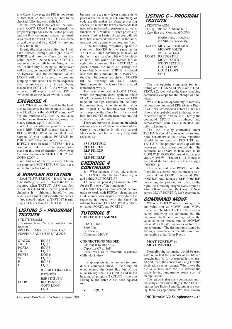
into Carry. However, the PIC is not awareof that fact, so the Carry bit has to bechecked following each shift left.
If the Carry bit is not yet set, the com-mand GOTO LOOP2 is performed, theprogram jumps back to that stated positionand the RLF command is again actioned.As a result the third l.e.d. (LD2) will comeon and the second l.e.d. (LD1) will go out,binary 00000100.
Eventually, after eight shifts, the 1 willhave shifted through all eight bits ofPORTB and into the Carry bit. At thispoint, there will be no bits set in PORTB,and so no l.e.d.s will be on. Now, on thetest for the Carry bit being set, the answerwill be true, command GOTO LOOP2 willbe bypassed and the command GOTOLOOP1 will be performed, the programjumping to that label. The whole sequencethen recommences by a 1 again beingloaded into PORTB bit 0. As written, theprogram will repeat until the PIC isswitched off or the Reset switch is used.
����� ���4.1. What do you think will be the l.e.d.
display sequence if another value is loadedinto PORTB via the MOVLW command?Try any multiple of 2; then try any valuethat has more than one bit set, using thebinary format, e.g. B’01001100’.
4.2. Also see what happens if the com-mand RRF PORTB,F is used instead ofRLF PORTB,F. What do you think willhappen if you replace PORTB,F byPORTB,W? Then see what happens ifBTFSC is used instead of BTFSS? (It is acommon mistake to use the wrong com-mand in this sort of situation.) Now swapthe two commands GOTO LOOP2 andGOTO LOOP1.
4.3. Just out of interest, also try deletingthe command BCF STATUS,C (just put asemicolon in front of it).
�� �������������Load TK3TUT5.HEX – it will be seen
to be shifting the l.e.d. display to the left, asoccurred when TK3TUT4.ASM was firstrun as TK3TUT4.HEX (before you startedchanging it – although, hopefully, yousaved each variant under a different name).
You should notice that TK3TUT5 is run-ning a bit faster than TK3TUT4 did. This is
because there are now fewer commands toprocess for the same result. Simplicity ofcode usually makes for faster processingspeeds (or, rather, the fewer commands thatneed to be processed to perform a particularfunction, will result in a faster processingspeed). Look at Listing 5 and you will seehow few commands there are in the loop,just two. Let’s examine the program flow.
In the full listing everything up to thestatement BANK0 is the same as inTK3TUT4. Then advantage is taken ofthe fact that a set Carry bit will be shift-ed into a file when it is rotated left orright; the command BSF STATUS,C isgiven before the loop, so setting theCarry bit. Now when PORTB is rotatedleft with the command RLF PORTB,F,the Carry bit comes straight into PORTBbit 0, turning on l.e.d. LD0.Simultaneously, the Carry bit is cleared(remember why?).
The next command is GOTO LOOP,which the program does, again to rotatePORTB, causing LD1 to come on and LD0to go out. For eight rotations left, the Carrybit remains clear, then on the ninth rotationthe original 1 that has traversed PORTBwill drop into the Carry bit, to be rotatedback into PORTB on the next rotation. Andso it goes on, indefinitely.
There are numerous situations in whichrotation occurs and when the setting of theCarry bit is desirable. In this way, severalfiles can be coupled as a very long shiftregister, e.g.:
BSF STATUS,CRLF FILE1,FRLF FILE2,Fetc. toRLF FILE15,F
����� ������������
4.4. What happens if you add anotherRLF PORTB,F after the first? And if youadd a third RLF PORTB,F?
4.5. What happens if you substitute a Wfor the F in one of the statements?
4.6. What happens if you amend the pro-gram to work with PORTA (changing thel.e.d. connections again) – why does thesequence not repeat with the Carry bitrotating back into PORTA? (What is differ-ent about PORTA and PORTB?)
��������*CONCEPTS EXAMINED
STATUS bit 2Zero flagBit code ZCommand MOVF
CONNECTIONS NEEDEDAll Port B to all l.e.d.s.Capacitor C7 as 1�FPreset VR1 set to minimum resistance
(fully clockwise)
It is appropriate at this moment to intro-duce a command allied to the Carry bittests, testing the Zero flag bit of theSTATUS register. This is bit 2 and in theheading of program TK3TUT6, shown inListing 6, the letter Z has been equatedto it:
Z EQU 2
The two opposite commands for zerotesting are BTFSS STATUS,Z and BTFSCSTATUS,Z, identical to the Carry checkingcommands except for the change of finalletter.
We also take the opportunity to formallydemonstrate command RRF (Rotate RightFile). It was described in Tutorial 4, but notshown. You probably used it, though, whenexperimenting with Exercise 4. Thirdly, thecommand MOVF is introduced anddemonstrated. Run TK3TUT6.HEX andrefer to Listing 6.
The l.e.d. display controlled underTK3TUT6 should be seen to be rotatingright, but otherwise the display repetitionshould be as seen in TK3TUT4 andTK3TUT5. The program opens up with thenecessary initialisation commands. Thecommand at LOOP1 is then seen to beMOVLW B’10000000’ instead of the pre-vious MOVLW 1. The set bit (1) is now atthe left of the byte, instead of at the right(00000001).
This is moved into PORTB and theCarry bit is cleared, both commands as inListing 4. At LOOP2, command RRFPORTB,F now replaces RLF PORTB,F,instructing the program to rotate to theright, the 1 moving progressively from bit7 to bit 0 and then into the Carry bit. Nextcomes MOVF PORTB,F. Let’s examine it.
������������Whereas MOVLW means moving a lit-
eral value into W, MOVF means MOVeFile value. The file (PORTB in this case) isnamed following the command, but thecommand itself does not say where thevalue is to be moved (unlike MOVLW,where W as the destination is included inthe command). The destination is stated byadding a comma after the file name andthen adding either W or F, e.g.:
MOVF PORTB,W orMOVF PORTB,F
Normally, the command would be usedwith W, so that the contents of the file arebrought into W for presumed further use.At first, then, the concept of using F as thedestination seems strange. Why move thefile value back into the file without thevalue having undergone some sort ofmanipulation?
The reason is that many commands auto-matically affect various flags in the STATUSregister (see Tables 1 and 4), setting or clear-ing them as appropriate. We have already
�� �����*�#������
�!���*
; TK3TUT5.ASM; Showing how Carry bit rotates intoregister#DEFINE BANK0 BCF STATUS,5#DEFINE BANK1 BSF STATUS,5
STATUS EQU 3TRISA EQU 5PORTA EQU 5TRISB EQU 6PORTB DQU 6W EQU 0F EQU 1C EQU 0
(ORG0 TO BANK0 aspreviously)
BSF STATUS,CLOOP RLF PORTB,F
GOTO LOOPEND
�� �������#������
�!����
; TK3TUT6.ASM; Using RRF and Z, Status bit 2; Zero flag use, Command MOVF
(Definitions, through toBANK0 as previously)
LOOP1 MOVLW B’10000000’MOVWF PORTBBCF STATUS,C
LOOP2 RRF PORTB,FMOVF PORTB,FBTFSS STATUS,ZGOTO LOOP2GOTO LOOP1END
Everyday Practical Electronics, April 2003 PIC Tutorial V2 Supplement – 15
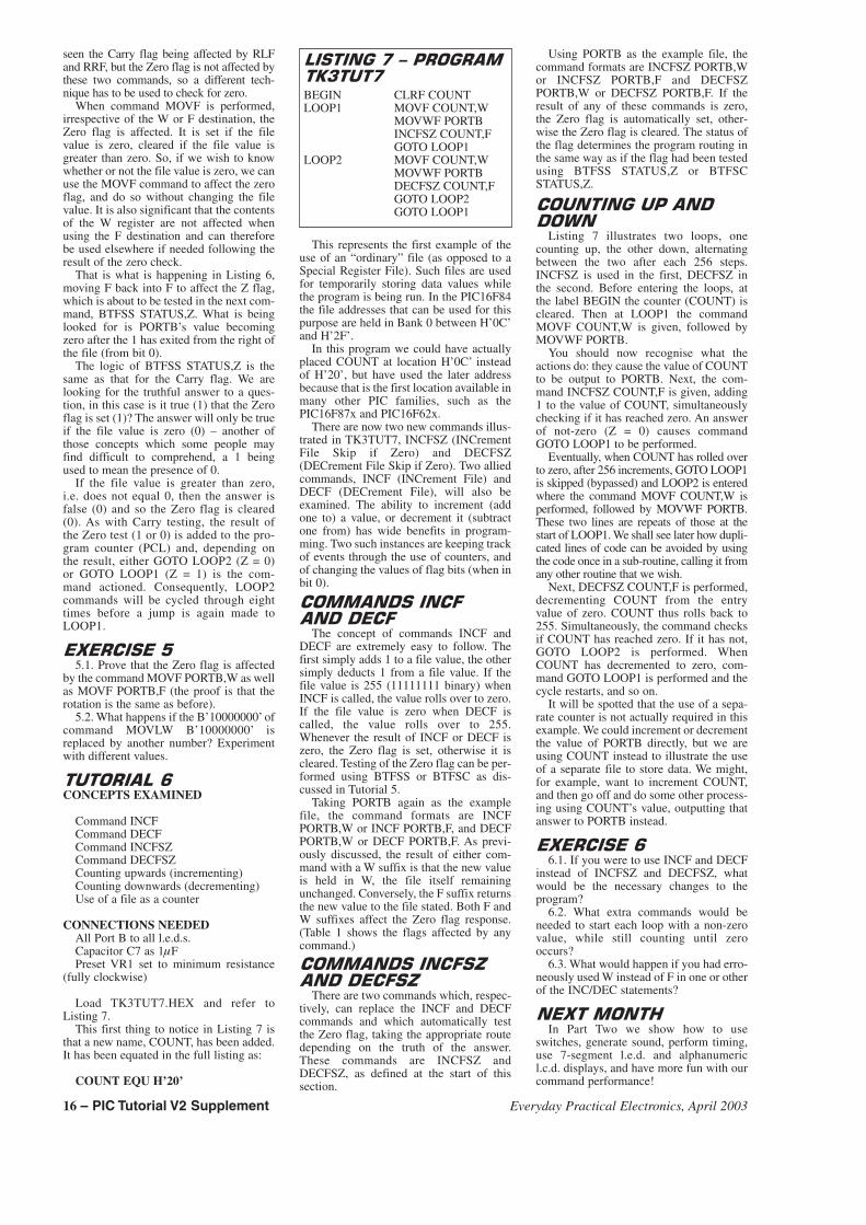
seen the Carry flag being affected by RLFand RRF, but the Zero flag is not affected bythese two commands, so a different tech-nique has to be used to check for zero.
When command MOVF is performed,irrespective of the W or F destination, theZero flag is affected. It is set if the filevalue is zero, cleared if the file value isgreater than zero. So, if we wish to knowwhether or not the file value is zero, we canuse the MOVF command to affect the zeroflag, and do so without changing the filevalue. It is also significant that the contentsof the W register are not affected whenusing the F destination and can thereforebe used elsewhere if needed following theresult of the zero check.
That is what is happening in Listing 6,moving F back into F to affect the Z flag,which is about to be tested in the next com-mand, BTFSS STATUS,Z. What is beinglooked for is PORTB’s value becomingzero after the 1 has exited from the right ofthe file (from bit 0).
The logic of BTFSS STATUS,Z is thesame as that for the Carry flag. We arelooking for the truthful answer to a ques-tion, in this case is it true (1) that the Zeroflag is set (1)? The answer will only be trueif the file value is zero (0) – another ofthose concepts which some people mayfind difficult to comprehend, a 1 beingused to mean the presence of 0.
If the file value is greater than zero,i.e. does not equal 0, then the answer isfalse (0) and so the Zero flag is cleared(0). As with Carry testing, the result ofthe Zero test (1 or 0) is added to the pro-gram counter (PCL) and, depending onthe result, either GOTO LOOP2 (Z = 0)or GOTO LOOP1 (Z = 1) is the com-mand actioned. Consequently, LOOP2commands will be cycled through eighttimes before a jump is again made toLOOP1.
����� ��*5.1. Prove that the Zero flag is affected
by the command MOVF PORTB,W as wellas MOVF PORTB,F (the proof is that therotation is the same as before).
5.2. What happens if the B’10000000’ ofcommand MOVLW B’10000000’ isreplaced by another number? Experimentwith different values.
���������CONCEPTS EXAMINED
Command INCFCommand DECFCommand INCFSZCommand DECFSZCounting upwards (incrementing)Counting downwards (decrementing)Use of a file as a counter
CONNECTIONS NEEDEDAll Port B to all l.e.d.s.Capacitor C7 as 1�FPreset VR1 set to minimum resistance
(fully clockwise)
Load TK3TUT7.HEX and refer toListing 7.
This first thing to notice in Listing 7 isthat a new name, COUNT, has been added.It has been equated in the full listing as:
COUNT EQU H’20’
This represents the first example of theuse of an “ordinary” file (as opposed to aSpecial Register File). Such files are usedfor temporarily storing data values whilethe program is being run. In the PIC16F84the file addresses that can be used for thispurpose are held in Bank 0 between H’0C’and H’2F’.
In this program we could have actuallyplaced COUNT at location H’0C’ insteadof H’20’, but have used the later addressbecause that is the first location available inmany other PIC families, such as thePIC16F87x and PIC16F62x.
There are now two new commands illus-trated in TK3TUT7, INCFSZ (INCrementFile Skip if Zero) and DECFSZ(DECrement File Skip if Zero). Two alliedcommands, INCF (INCrement File) andDECF (DECrement File), will also beexamined. The ability to increment (addone to) a value, or decrement it (subtractone from) has wide benefits in program-ming. Two such instances are keeping trackof events through the use of counters, andof changing the values of flag bits (when inbit 0).
������� �������� ����
The concept of commands INCF andDECF are extremely easy to follow. Thefirst simply adds 1 to a file value, the othersimply deducts 1 from a file value. If thefile value is 255 (11111111 binary) whenINCF is called, the value rolls over to zero.If the file value is zero when DECF iscalled, the value rolls over to 255.Whenever the result of INCF or DECF iszero, the Zero flag is set, otherwise it iscleared. Testing of the Zero flag can be per-formed using BTFSS or BTFSC as dis-cussed in Tutorial 5.
Taking PORTB again as the examplefile, the command formats are INCFPORTB,W or INCF PORTB,F, and DECFPORTB,W or DECF PORTB,F. As previ-ously discussed, the result of either com-mand with a W suffix is that the new valueis held in W, the file itself remainingunchanged. Conversely, the F suffix returnsthe new value to the file stated. Both F andW suffixes affect the Zero flag response.(Table 1 shows the flags affected by anycommand.)
������� ����� +��� ���� +
There are two commands which, respec-tively, can replace the INCF and DECFcommands and which automatically testthe Zero flag, taking the appropriate routedepending on the truth of the answer.These commands are INCFSZ andDECFSZ, as defined at the start of thissection.
Using PORTB as the example file, thecommand formats are INCFSZ PORTB,Wor INCFSZ PORTB,F and DECFSZPORTB,W or DECFSZ PORTB,F. If theresult of any of these commands is zero,the Zero flag is automatically set, other-wise the Zero flag is cleared. The status ofthe flag determines the program routing inthe same way as if the flag had been testedusing BTFSS STATUS,Z or BTFSCSTATUS,Z.
�������������������
Listing 7 illustrates two loops, onecounting up, the other down, alternatingbetween the two after each 256 steps.INCFSZ is used in the first, DECFSZ inthe second. Before entering the loops, atthe label BEGIN the counter (COUNT) iscleared. Then at LOOP1 the commandMOVF COUNT,W is given, followed byMOVWF PORTB.
You should now recognise what theactions do: they cause the value of COUNTto be output to PORTB. Next, the com-mand INCFSZ COUNT,F is given, adding1 to the value of COUNT, simultaneouslychecking if it has reached zero. An answerof not-zero (Z = 0) causes commandGOTO LOOP1 to be performed.
Eventually, when COUNT has rolled overto zero, after 256 increments, GOTO LOOP1is skipped (bypassed) and LOOP2 is enteredwhere the command MOVF COUNT,W isperformed, followed by MOVWF PORTB.These two lines are repeats of those at thestart of LOOP1. We shall see later how dupli-cated lines of code can be avoided by usingthe code once in a sub-routine, calling it fromany other routine that we wish.
Next, DECFSZ COUNT,F is performed,decrementing COUNT from the entryvalue of zero. COUNT thus rolls back to255. Simultaneously, the command checksif COUNT has reached zero. If it has not,GOTO LOOP2 is performed. WhenCOUNT has decremented to zero, com-mand GOTO LOOP1 is performed and thecycle restarts, and so on.
It will be spotted that the use of a sepa-rate counter is not actually required in thisexample. We could increment or decrementthe value of PORTB directly, but we areusing COUNT instead to illustrate the useof a separate file to store data. We might,for example, want to increment COUNT,and then go off and do some other process-ing using COUNT’s value, outputting thatanswer to PORTB instead.
����� ���6.1. If you were to use INCF and DECF
instead of INCFSZ and DECFSZ, whatwould be the necessary changes to theprogram?
6.2. What extra commands would beneeded to start each loop with a non-zerovalue, while still counting until zerooccurs?
6.3. What would happen if you had erro-neously used W instead of F in one or otherof the INC/DEC statements?
����������In Part Two we show how to use
switches, generate sound, perform timing,use 7-segment l.e.d. and alphanumericl.c.d. displays, and have more fun with ourcommand performance!
�� �����,�#������
�!���,
BEGIN CLRF COUNTLOOP1 MOVF COUNT,W
MOVWF PORTBINCFSZ COUNT,FGOTO LOOP1
LOOP2 MOVF COUNT,WMOVWF PORTBDECFSZ COUNT,FGOTO LOOP2GOTO LOOP1
16 – PIC Tutorial V2 Supplement Everyday Practical Electronics, April 2003